BACKGROUND OF THE INVENTION
1. Field of the Invention
-
This invention relates generally to a weighted surface acoustic
wave (SAW) reflector for use in a SAW reflector filter or SAW resonator and,
more particularly, to a weighted SAW reflector for use in a SAW reflector filter
or resonator, where the reflector includes reflector grid lines selectively
dithered relative to uniformly spaced grid lines that have M grid lines per each
Nλ, where λ is the wavelength of the center frequency of the frequency band
of interest, M and N are integers and M>N.
2. Discussion of the Related Art
-
Intermediate frequency (IF) filters are employed for channel
selection in mobile phone communications systems, such as CDMA and
GSM. The IF filters must be small in size and provide narrow bandwidths with
steep transition edges and good out of band rejection. One type of filter that
provides these properties is known in the art as a surface acoustic wave
(SAW) filter.
-
Conventional SAW filters include an input transducer and an
output transducer formed on a piezoelectric substrate. The input transducer
is electrically excited with the electrical input signal that is to be filtered. The
input transducer converts the electrical input signal to surface acoustic waves,
such as Rayleigh waves, lamb waves, etc., that propagate along the
substrate to the output transducer. The output transducer converts the
acoustic waves to a filtered electrical signal.
-
The input and output transducers typically include interdigital
electrodes formed on the top surface of the substrate. The shape and
spacing of the electrodes determines the center frequency and the band
shape of the acoustic waves produced by the input transducer. Generally,
the smaller the width of the electrodes, or the number of electrodes per
wavelength, the higher the operating frequency. The amplitude of the surface
acoustic waves at a particular frequency is determined by the constructive
interference of the acoustic waves generated by the transducers.
-
The combined length of the transducers determines the length
of the overall filter. To design a conventional SAW filter with ideal filter
characteristics, the filter's impulse response needs to be very long. Because
the length of the impulse response is directly proportional to the length of the
transducer, the overall length of a conventional SAW filter having ideal
characteristics would be too long to be useful in mobile phone
communications systems.
-
Reflective SAW filters have been developed to satisfy this
problem. Reflective SAW filters generally have at least one input transducer,
one output transducer and one reflector formed on a piezoelectric substrate.
The reflector is typically a reflective grating including spaced apart grid lines
defining gaps therebetween. The acoustic waves received by the reflector
from the input transducer are reflected by the grid lines within the grating so
that the reflected waves constructively and destructively interfere with each
other and the wave path is folded. The constructively interfered waves are
reflected back to the output transducer having a particular phase. Because of
the folding, the length of the transducer is no longer dependent on the
duration of the impulse response. Reflective SAW filters are, therefore,
smaller in size and have high frequency selectivity, and thus are desirable for
mobile phone communication systems.
-
The frequency response of a reflective SAW filter is further
improved by weighting the individual reflectors to achieve a desired net
reflectivity. Existing weighting methods include position-weighting, omission-weighting,
and strip-width weighting. Other methods of weighting reflectors
include changing the lengths of open-circuited reflective strips within an open-short
reflector structure. Weighting the reflector helps to reduce the physical
size of the filter and to improve the filters frequency response.
-
An ideal frequency response for a reflector SAW filter has steep
transition edges. The reflective gratings in a reflector SAW filter are weighted
by a suitable weighting function to provide the desired filter response. For
example, a weighted sin(x)/x function can be implemented in each reflective
grating to generate a filter response having very steep transition edges.
-
Existing weighting techniques include position-weighting,
omission-weighting and strip-width weighting. Other methods of weighting
reflective gratings include changing the length of open-circuited reflective
strips within an open-short reflector structure. Weighting the reflective grating
helps to reduce the physical size of the filter and improve the filters frequency
response.
-
The weighted reflective grating acts as a key element in the
reflector SAW filter by reducing the physical size of the filter and improving
the electrical filter response. A size reduction of 70% and an insertion loss of
around 8 dB has been reported in the art using a Z-path reflector filter
compared to in-line filter structures. One known reflective filter is a Z-path IF
SAW filter for CDMA mobile phones.
-
The known methods of weighting a reflective grating in a SAW
filter are all dependent upon the critical dimension of the reflector structure.
The critical dimension is the smaller of the reflective grating grid width or the
gap width, and is inversely proportional to the operating frequency of the filter.
As the operating frequency increases, the critical dimension decreases.
Fabrication constraints limit the critical dimension, thus limiting the operating
frequency of the filter. As the operating frequency of the filter increases, the
known reflective gratings have a limited dynamic range when implementing a
wide range of reflectivity, which is required for filters with high selectivity. A
reflective grating that provides strong reflectivity at a given frequency and
critical dimension would be advantageous.
BRIEF SUMMARY OF THE INVENTION
-
In accordance with the teachings of the present invention, a new
type of reflective grating for a SAW filter or resonator is disclosed. The
grating is formed by selectively dithering grating grid lines with respect to a
predetermined uniform or periodic spaced grid lines defined by M grid lines
per each N wavelength (Nλ/M), where λ is the wavelength of the center
frequency of the frequency, fo, band of interest, M and N are integers and
M>N. M and N are selected so that the grating does not have a net reflection
when all of the grid lines are uniformly spaced, i.e., no dithering. λ is defined
as V/fo, where V is the propagation velocity of the surface acoustic waves on
the substrate. By providing a specific dithering pattern of the grid lines in
each sampling period of Nλ, any desired net distributed reflectivity from the
grating can be implemented in both magnitude and phase.
-
Additional advantages and features of the present invention will
become apparent from the following description and appended claims, taken
in conjunction with the accompanying drawings.
BRIEF DESCRIPTION OF THE DRAWINGS
-
Figure 1 is a top plan view of a reflector SAW filter including a
reflective grating, according to an embodiment of the present invention;
-
Figure 2 is a graphical representation of the reflectivity function
of a reflective grating, according to the invention, having a normalized λ/4
sampling period;
-
Figure 3 is a graphical representation of the frequency response
of a reflective grating, according to the invention, having a normalized λ/4
sampling period;
-
Figure 4 is a top plan view of a weighted reflective grating that
can be used in the SAW filter shown in figure 1, where the grating has
sampling periods of λ and (0,0,1,-1) dithered grid lines in each period,
according to an embodiment of the present invention;
-
Figure 5 is a graphical representation of dithered reflector
strength vs grating position for the reflective grating shown in figure 4;
-
Figure 6 is a top plan view of a weighted reflective grating that
can be used in the SAW filter shown in figure 1, where the reflective grating
has sampling periods of λ and (1, -1,1,-1) dithered grid lines in each period,
according to another embodiment of the present invention;
-
Figure 7 is a graphical representation of dithered reflector
strength vs grating position for the reflective grating shown in figure 6;
-
Figure 8 is a top plan view of a weighted reflective grating that
can be used in the SAW filter shown in figure 1, where the reflective grating
has sampling periods of 3λ/5 and (1, -0.35, -0.35, 0.8, 1) dithered grid lines in
each period, according to another embodiment of the present invention;
-
Figure 9 is a graphical representation of dithered reflector
strength vs grating position for the reflective grating shown in figure 8; and
-
Figures 10(a) - 10(c) show variations of the dithered grating
structure of the invention.
DETAILED DESCRIPTION OF THE INVENTION
-
The following discussion of the embodiments of the invention
directed to a weighted surface acoustic wave reflector for a SAW filter, where
the reflector includes dithered reflector grid lines, is merely exemplary in
nature, and is in no way intended to limit the invention or its application or
uses.
-
Figure 1 is a top view of a reflective SAW filter 10 fabricated on
a piezoelectric substrate 12, according to an embodiment of the present
invention. The reflective SAW filter 10 includes a bi-directional input
transducer 14, an output bi-directional transducer 16, and a reflective grating
18, according to the invention. The input transducer 14 and the output
transducer 16 include a plurality of uniformly spaced interdigital electrode
fingers 20 attached at opposite ends by bus bars 22. The reflective SAW
filter 10 is excited by an input signal that is to be filtered applied to the input
transducer 14 on input line 24. The input transducer 14 converts the
electrical signal into surface acoustic waves 28. The surface acoustic waves
28 propagate outward from the input transducer 12 along the surface of the
piezoelectric substrate 12.
-
Approximately half of the acoustic waves 28 are received by the
output transducer 16 where they are converted back into electrical energy on
an output line 30. The other half of the acoustic propagated waves 28 are
received by the reflective grating 18, and are then reflected back through the
input transducer 14 to the output transducer 16 where they are converted
back into electrical energy. In a working embodiment, the filter 10 would
include two input transducers and two output transducers to correct for signal
cancellation at the output transducer 16, as is well understood to those skilled
in the art. As will be discussed below, the reflective grating 18 employs
dithered grating lines that optimize the reflecting ability of the grating 18 for a
particular wavelength.
-
It is noted that in order for the filter 10 to operate properly, a
second reflective track should be included that also includes an input
transducer, an output transducer and a reflective grating. The two input
transducers would have the same polarity and the two output transducers
would have opposite polarities. Thus, the surface acoustic waves that are
directly received by the output transducer from the associated input
transducer, and are not reflected by the reflective grating, are in phase with
each other at the output transducer of the filter, and thus cancel because the
two output transducers have opposite polarities. The acoustic waves that are
reflected by the reflective gratings reach the associated output transducers
180° out of phase with each other, and therefore add at the output because
the two output transducers have opposite polarities. The 180° phase
difference between the grating reflections can be provided by several
techniques, including providing a delay in one of the tracks relative to the
other track where the acoustic waves in the two tracks propagate a λ/2
difference in distance. This delay can be provided by an offset between the
reflective gratings in the two tracks of λ/4.
-
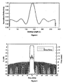
Figure 2 is a graphical representation of the reflectivity function
of the reflective grating 18 with λ/4 sampling. According to the invention, the
sampling period is defined by M grid lines per each N wavelength (Nλ/M),
where λ is the wavelength of the center frequency of the frequency band of
interest, M and N are integers and M>N. Examples of sampling periods that
satisfy this requirement include, but are not limited to, λ/4, λ/3, 2λ/5, 3λ/7,
3λ/8, 4λ/7, and 5λ/8. A characteristic of a sampling period meeting this
requirement is that if the reflective grating 18 had grid lines that were
uniformly spaced or periodic, i.e., no dithering, the grating 18 would have no
net reflectivity. The critical dimension, CD, of the transducer is proportional to
the grid line period, Nλ/M. Since λ=V/fo, fo is proportional to N/(M*CD). The
larger the ratio N/M, the higher the grating center frequency will be for a given
CD.
-
As discussed above, a reflective grating having the Nλ/M
orientation of grid lines would provide reflections of the surface acoustic
waves within the grid lines that have the proper phase to destructively
interfere and provide no net reflectivity. The desired reflectivity is achieved by
dithering or changing the position of the grid lines relative to the uniform
spacing according to a predetermined dithering function, discussed below.
The dithering function is selected to control the magnitude and phase of the
reflected acoustic waves so that they are coupled together to provide the
desired reflection at the center of the frequency band of interest. The shape
of the frequency response is an ideal reflectivity function that will produce a
filter with ideal characteristics.
-
Figure 3 is a graphical representation of the frequency response
for the reflective grating 18 that has the reflective characteristics shown in
Figure 2. Figure 3 illustrates what is known in the art as a "brick wall"
frequency response. The brick wall frequency response is an ideal response
that has steep transition edges and a narrow bandwidth. A reflective grating
with the reflectivity function of Figure 2 will produce the "brick wall" frequency
response shown in Figure 3.
-
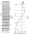
Figure 4 is a top plan view of a reflective grating 36 that can be
used in place of the reflective grating 18 in the filter 10, according to the
present invention. Figure 5 is a graphical representation of dithered reflector
strength versus grating position for the grating 36. A graph line 48 identifies
the magnitude and phase of the reflected surface acoustic waves at that
location in the grating 36. As will be discussed below, the reflective grating
36 provides a reflectivity function so that an incident surface acoustic wave 32
is reflected back in the opposite direction as a reflected surface acoustic
waves 34 having the desired amplitude and phase for the frequency band of
interest.
-
The reflective grating 36 includes a series of spaced apart grid
lines 38 defining gaps 40 therebetween. The width of the grid lines 38 and
the gaps 40 are based on a uniform grid spacing of M grid lines 38 per each
Nλ, as discussed above. For a uniform or periodic grid line orientation, each
of the grid lines 38 and the gaps 40 all have the same width in the
propagation direction of the surface acoustic waves 32. The uniform grid line
spacing thus provides no net reflectivity. In accordance with the teachings of
the present invention, some of the grid lines 38 are dithered relative to the
uniform spacing to provide the desired net reflectivity (phase and magnitude)
for a particular center frequency. The dithered grid lines 44 in the grating 36
are identified from the non-dithered or uniform grid lines 46 by being shaded.
-
In this embodiment, the spacing of the grid lines 38 is identified
by a sampling period 42, where each sampling period 42 includes four grid
lines 38 spaced across a distance equal to one wavelength (λ) of the center
frequency. Further, in this embodiment, each grid line 38 and uniform
spacing gap 40 has a width of λ/8 relative to the center frequency being
filtered. The vertical graph lines in figures 4 and 5 identify the separation of
the sampling periods 42. In one embodiment, the grating 36 has 275
sampling periods or is 275 λ long.
-
The dithering of the grid lines 38 follows a predetermined
sequence. For example, between vertical graph lines 50 and 52 the dithering
of the grid lines 38 in each sampling period 42 has one dithering orientation,
and between the vertical graph lines 52 and 54 the dithering of the grid lines
38 in each sampling period 42 has another orientation, where the sequences
alternate across the complete reflective grating 36. The phase of the
reflectivity function changes by 180° from one side of the line 52 to the other.
-
According to the invention, the dithering of the grid lines 38 in
the sampling period 42 is defined by a number between -1 and 1. A zero
means that the grid line 38 has not been dithered relative to the uniform
spacing, a positive number means that the grid line 38 has been dithered to
the right a certain amount, and a negative number means that the grid line 38
has been dithered to the left a certain amount. In this example, -1 and 1
dithering represent the maximum distance that the grid line 38 can be dithered.
In this embodiment, a -1 and 1 dithering is halfway across the gap 40. The
amount of maximum dithering can be more than halfway across the gap as
long as the critical dimension, which is the smallest gap in the grating, is within
the feasible limit of lithography.
-
The dithering orientation in the sampling periods 42 between the
vertical graph lines 50 and 52 is identified by the sequence (0, 0, 1, -1). The
values in the dithering sequence show the relative displacement of each grid
line within a sampling period. This means that the first and second grid lines
38 have not been dithered, the third grid line can be dithered to the right
between zero and the maximum amount, and the fourth grid line 38 can be
dithered to the left between zero and the maximum amount. However, both
of the third and fourth grid lines within the same period will be dithered the
same amount. The dithering orientation in the sampling periods 42 between
the vertical graph lines 52 and 54 has the dithering sequence (-1, 1, 0, 0).
This means that the first grid line 38 can be dithered between zero and the
maximum distance to the left, the second grid line can be dithered between
zero and the maximum distance to the right, and the third and fourth grid lines
38 have not been dithered relative to the uniform spacing. However, both the
first and second grid lines within the same period will be dithered the same
amount. The graph line 48 gives the magnitude and phase of the reflections
for this dithered sequence. Since the SAW propagation velocity, V, is a
function of the dithered magnitude, the λ of each sampling period must be
adjusted according to the dithered sequence in order for the SAW to
propagate properly throughout the grating.
-
Figure 6 is a top view of a reflective grating 70 that can be used
as the reflective grating 18 in the filter 10, according to another embodiment
of the present invention. Figure 7 is a graphical representation of dithered
reflective strength versus grating position of the grating 70, as will be
discussed below. The reflective grating 70 is similar to the reflective grating
36 discussed above, where like referenced numerals will be used to identify
the same elements. The sampling period 42 of the reflective grating 70
provides the same reflectivity function as the reflective grating 36, as shown
by the graph line 48 in Figures 5 and 7.
-
The reflective grating 70 also includes a sampling period 42 of
four grid lines 38, where Nλ/M=λ/4. The dithered sequence of the grid lines
38 between the graph lines 50 and 52 is (1, -1, 1, -1), and the dithered
sequence of the grid lines 38 between the graph lines 52 and 54 is (-1, 1, -1,
1). Therefore, all of the grid lines 38 in the grating 70 can be dithered
between zero and the maximum amount, either to the right or to the left.
However, all four grid lines within the same period will be dithered the same
amount. Thus, the same reflectivity function can be provided by different
dithered sequences.
-
The reflectivity phase changes by 180° by reversing the
dithering direction of each reflection. In general, if the reflection center of one
sampling period 42 is spatially offset by λ/4 with respect to that of another
period, the reflectivities of the two periods will be 180° out of phase. It is clear
from Figures 4-7 that as the values of the dithering sequence within each
sampling period 42 decreases, the reflectivity magnitude of that period 42
decreases. Similar grating reflectivity can be achieved by using different
sampling periods.
-
Figure 8 is a top view of a reflective grating 80 that can be used
as the reflective grating 18 in the filter 10, according to another embodiment
of the present invention. Likewise, figure 9 is a graphical representation of
dithered reflective strength versus grating position of the grating 80. As
above, like referenced numerals represent like elements. The reflective
grating 80 has a different sampling period 82 than the sampling period 42
shown in Figures 4 and 6 that can be employed to provide the same
reflectivity function as shown in Figures 5, 7, and 9. In this embodiment, each
sampling period 82 includes five grid lines 38 and has a width of 3λ. Further,
each grid line 38 and each gap 40 has a width of 3λ/10. The dithering
sequence for the section of the reflective grating 80 between the graph lines
50 and 52 is (-1, -0.35, -0.35, 0.8, 1), and the dithering sequence for the
reflective grating 80 between the grid lines 52 and 54 is (0.35, 1, 0, -0.8,
0.35). Again, the values in the dithering sequence show the relative
displacement of each grid line within a sampling period.
-
The grid lines 38 can be formed on the piezoelectric substrate
12 by any suitable technique. For example, figure 10(a) is a top plan view of
a reflective grating 90 having dithered grid lines 92 defining gaps 94
therebetween. The grid lines 92 are coupled at their ends to opposing end
bus bars 96 and 98, as shown, to provide a grid short circuit. The reflective
gratings 36, 70 and 80 do not have end bus bars, and thus provide an open
circuited design. In this embodiment, the grid lines 92 and the bus bars 96
and 98 are metal deposited on the substrate.
-
Figure 10(b) is a top plan view of a reflective grating 100,
according to the invention, including a series of spaced apart and dithered
grid lines 102 defining gaps 104 therebetween. The grid lines 102 can be
formed by any suitable grating material, such as metal, any suitable
substance deposited on the substrate, an etched groove below the substrate,
ion implantation into the substrate, or any kind of disturbance in the substrate
that provides the particular desired dithered pattern.
-
Figure 10(c) is a top plan view of a grating 110 including tapered
grid lines 112. The tapered grid lines 112 provide a suitable reflectivity
channel for adjacent frequency bands for multiple communication channels.
The grid lines 112 are provided by connecting N channels of grating lines
from top to bottom in an ascending or descending order for the desired
wavelengths. Various embodiments of the reflective gratings depicted in
Figure 10(a) and Figure 10(b) can also be applied to the tapered reflective
grating 112.
-
The foregoing discussion discloses and describes merely
exemplary embodiments of the present invention. One skilled in the art will
readily recognize from such discussion and from the accompanying drawings
and claims that various changes, modifications and variations can be made
therein without departing from the spirit and scope of the invention as defined
in the following claims.