EP1469199A2 - Compressor coating - Google Patents
Compressor coating Download PDFInfo
- Publication number
- EP1469199A2 EP1469199A2 EP04008761A EP04008761A EP1469199A2 EP 1469199 A2 EP1469199 A2 EP 1469199A2 EP 04008761 A EP04008761 A EP 04008761A EP 04008761 A EP04008761 A EP 04008761A EP 1469199 A2 EP1469199 A2 EP 1469199A2
- Authority
- EP
- European Patent Office
- Prior art keywords
- piston
- sliding
- swash plate
- drive shaft
- compressor according
- Prior art date
- Legal status (The legal status is an assumption and is not a legal conclusion. Google has not performed a legal analysis and makes no representation as to the accuracy of the status listed.)
- Granted
Links
- 238000000576 coating method Methods 0.000 title description 9
- 239000011248 coating agent Substances 0.000 title description 8
- 239000011347 resin Substances 0.000 claims abstract description 64
- 229920005989 resin Polymers 0.000 claims abstract description 64
- 239000000843 powder Substances 0.000 claims abstract description 53
- 239000011230 binding agent Substances 0.000 claims abstract description 50
- 239000000314 lubricant Substances 0.000 claims abstract description 48
- 239000007787 solid Substances 0.000 claims abstract description 48
- GWEVSGVZZGPLCZ-UHFFFAOYSA-N Titan oxide Chemical compound O=[Ti]=O GWEVSGVZZGPLCZ-UHFFFAOYSA-N 0.000 claims abstract description 47
- OGIDPMRJRNCKJF-UHFFFAOYSA-N titanium oxide Inorganic materials [Ti]=O OGIDPMRJRNCKJF-UHFFFAOYSA-N 0.000 claims abstract description 41
- 239000010954 inorganic particle Substances 0.000 claims description 27
- 239000006087 Silane Coupling Agent Substances 0.000 claims description 23
- 230000006835 compression Effects 0.000 claims description 23
- 238000007906 compression Methods 0.000 claims description 23
- 239000008199 coating composition Substances 0.000 claims description 22
- 229920002312 polyamide-imide Polymers 0.000 claims description 17
- 239000004962 Polyamide-imide Substances 0.000 claims description 15
- 239000007822 coupling agent Substances 0.000 claims description 15
- 239000011164 primary particle Substances 0.000 claims description 15
- 229920001343 polytetrafluoroethylene Polymers 0.000 claims description 7
- 239000004810 polytetrafluoroethylene Substances 0.000 claims description 7
- -1 polytetrafluoroethylene Polymers 0.000 claims description 3
- 229910045601 alloy Inorganic materials 0.000 description 16
- 239000000956 alloy Substances 0.000 description 16
- 239000000758 substrate Substances 0.000 description 15
- VYPSYNLAJGMNEJ-UHFFFAOYSA-N Silicium dioxide Chemical compound O=[Si]=O VYPSYNLAJGMNEJ-UHFFFAOYSA-N 0.000 description 10
- XAGFODPZIPBFFR-UHFFFAOYSA-N aluminium Chemical compound [Al] XAGFODPZIPBFFR-UHFFFAOYSA-N 0.000 description 10
- 229910052782 aluminium Inorganic materials 0.000 description 10
- 230000000694 effects Effects 0.000 description 7
- 230000007246 mechanism Effects 0.000 description 7
- DQZNLOXENNXVAD-UHFFFAOYSA-N trimethoxy-[2-(7-oxabicyclo[4.1.0]heptan-4-yl)ethyl]silane Chemical compound C1C(CC[Si](OC)(OC)OC)CCC2OC21 DQZNLOXENNXVAD-UHFFFAOYSA-N 0.000 description 7
- SECXISVLQFMRJM-UHFFFAOYSA-N N-Methylpyrrolidone Chemical compound CN1CCCC1=O SECXISVLQFMRJM-UHFFFAOYSA-N 0.000 description 6
- 239000003507 refrigerant Substances 0.000 description 6
- 238000005057 refrigeration Methods 0.000 description 6
- 238000005507 spraying Methods 0.000 description 6
- 238000012360 testing method Methods 0.000 description 6
- OTARVPUIYXHRRB-UHFFFAOYSA-N diethoxy-methyl-[3-(oxiran-2-ylmethoxy)propyl]silane Chemical compound CCO[Si](C)(OCC)CCCOCC1CO1 OTARVPUIYXHRRB-UHFFFAOYSA-N 0.000 description 5
- CWQXQMHSOZUFJS-UHFFFAOYSA-N molybdenum disulfide Chemical compound S=[Mo]=S CWQXQMHSOZUFJS-UHFFFAOYSA-N 0.000 description 5
- 229910052982 molybdenum disulfide Inorganic materials 0.000 description 5
- HBMJWWWQQXIZIP-UHFFFAOYSA-N silicon carbide Chemical compound [Si+]#[C-] HBMJWWWQQXIZIP-UHFFFAOYSA-N 0.000 description 5
- 239000000377 silicon dioxide Substances 0.000 description 5
- JXUKBNICSRJFAP-UHFFFAOYSA-N triethoxy-[3-(oxiran-2-ylmethoxy)propyl]silane Chemical compound CCO[Si](OCC)(OCC)CCCOCC1CO1 JXUKBNICSRJFAP-UHFFFAOYSA-N 0.000 description 5
- BPSIOYPQMFLKFR-UHFFFAOYSA-N trimethoxy-[3-(oxiran-2-ylmethoxy)propyl]silane Chemical compound CO[Si](OC)(OC)CCCOCC1CO1 BPSIOYPQMFLKFR-UHFFFAOYSA-N 0.000 description 5
- 239000002966 varnish Substances 0.000 description 5
- LVNLBBGBASVLLI-UHFFFAOYSA-N 3-triethoxysilylpropylurea Chemical compound CCO[Si](OCC)(OCC)CCCNC(N)=O LVNLBBGBASVLLI-UHFFFAOYSA-N 0.000 description 4
- PRKPGWQEKNEVEU-UHFFFAOYSA-N 4-methyl-n-(3-triethoxysilylpropyl)pentan-2-imine Chemical compound CCO[Si](OCC)(OCC)CCCN=C(C)CC(C)C PRKPGWQEKNEVEU-UHFFFAOYSA-N 0.000 description 4
- 238000004891 communication Methods 0.000 description 4
- 230000003247 decreasing effect Effects 0.000 description 4
- 239000000203 mixture Substances 0.000 description 4
- KBJFYLLAMSZSOG-UHFFFAOYSA-N n-(3-trimethoxysilylpropyl)aniline Chemical compound CO[Si](OC)(OC)CCCNC1=CC=CC=C1 KBJFYLLAMSZSOG-UHFFFAOYSA-N 0.000 description 4
- FRGPKMWIYVTFIQ-UHFFFAOYSA-N triethoxy(3-isocyanatopropyl)silane Chemical compound CCO[Si](OCC)(OCC)CCCN=C=O FRGPKMWIYVTFIQ-UHFFFAOYSA-N 0.000 description 4
- CTQNGGLPUBDAKN-UHFFFAOYSA-N O-Xylene Chemical compound CC1=CC=CC=C1C CTQNGGLPUBDAKN-UHFFFAOYSA-N 0.000 description 3
- 238000004378 air conditioning Methods 0.000 description 3
- PNEYBMLMFCGWSK-UHFFFAOYSA-N aluminium oxide Inorganic materials [O-2].[O-2].[O-2].[Al+3].[Al+3] PNEYBMLMFCGWSK-UHFFFAOYSA-N 0.000 description 3
- 238000006073 displacement reaction Methods 0.000 description 3
- 230000004048 modification Effects 0.000 description 3
- 238000012986 modification Methods 0.000 description 3
- 239000002904 solvent Substances 0.000 description 3
- 239000008096 xylene Substances 0.000 description 3
- OKTJSMMVPCPJKN-UHFFFAOYSA-N Carbon Chemical compound [C] OKTJSMMVPCPJKN-UHFFFAOYSA-N 0.000 description 2
- 229920000840 ethylene tetrafluoroethylene copolymer Polymers 0.000 description 2
- 229910002804 graphite Inorganic materials 0.000 description 2
- 239000010439 graphite Substances 0.000 description 2
- 239000004615 ingredient Substances 0.000 description 2
- 238000005259 measurement Methods 0.000 description 2
- 229920001721 polyimide Polymers 0.000 description 2
- 230000003746 surface roughness Effects 0.000 description 2
- WYTZZXDRDKSJID-UHFFFAOYSA-N (3-aminopropyl)triethoxysilane Chemical compound CCO[Si](OCC)(OCC)CCCN WYTZZXDRDKSJID-UHFFFAOYSA-N 0.000 description 1
- LTQBNYCMVZQRSD-UHFFFAOYSA-N (4-ethenylphenyl)-trimethoxysilane Chemical compound CO[Si](OC)(OC)C1=CC=C(C=C)C=C1 LTQBNYCMVZQRSD-UHFFFAOYSA-N 0.000 description 1
- DOYKFSOCSXVQAN-UHFFFAOYSA-N 3-[diethoxy(methyl)silyl]propyl 2-methylprop-2-enoate Chemical compound CCO[Si](C)(OCC)CCCOC(=O)C(C)=C DOYKFSOCSXVQAN-UHFFFAOYSA-N 0.000 description 1
- IKYAJDOSWUATPI-UHFFFAOYSA-N 3-[dimethoxy(methyl)silyl]propane-1-thiol Chemical compound CO[Si](C)(OC)CCCS IKYAJDOSWUATPI-UHFFFAOYSA-N 0.000 description 1
- LZMNXXQIQIHFGC-UHFFFAOYSA-N 3-[dimethoxy(methyl)silyl]propyl 2-methylprop-2-enoate Chemical compound CO[Si](C)(OC)CCCOC(=O)C(C)=C LZMNXXQIQIHFGC-UHFFFAOYSA-N 0.000 description 1
- OXYZDRAJMHGSMW-UHFFFAOYSA-N 3-chloropropyl(trimethoxy)silane Chemical compound CO[Si](OC)(OC)CCCCl OXYZDRAJMHGSMW-UHFFFAOYSA-N 0.000 description 1
- URDOJQUSEUXVRP-UHFFFAOYSA-N 3-triethoxysilylpropyl 2-methylprop-2-enoate Chemical compound CCO[Si](OCC)(OCC)CCCOC(=O)C(C)=C URDOJQUSEUXVRP-UHFFFAOYSA-N 0.000 description 1
- SJECZPVISLOESU-UHFFFAOYSA-N 3-trimethoxysilylpropan-1-amine Chemical compound CO[Si](OC)(OC)CCCN SJECZPVISLOESU-UHFFFAOYSA-N 0.000 description 1
- UUEWCQRISZBELL-UHFFFAOYSA-N 3-trimethoxysilylpropane-1-thiol Chemical compound CO[Si](OC)(OC)CCCS UUEWCQRISZBELL-UHFFFAOYSA-N 0.000 description 1
- XDLMVUHYZWKMMD-UHFFFAOYSA-N 3-trimethoxysilylpropyl 2-methylprop-2-enoate Chemical compound CO[Si](OC)(OC)CCCOC(=O)C(C)=C XDLMVUHYZWKMMD-UHFFFAOYSA-N 0.000 description 1
- KBQVDAIIQCXKPI-UHFFFAOYSA-N 3-trimethoxysilylpropyl prop-2-enoate Chemical compound CO[Si](OC)(OC)CCCOC(=O)C=C KBQVDAIIQCXKPI-UHFFFAOYSA-N 0.000 description 1
- 229910000838 Al alloy Inorganic materials 0.000 description 1
- 229910000975 Carbon steel Inorganic materials 0.000 description 1
- VEXZGXHMUGYJMC-UHFFFAOYSA-N Hydrochloric acid Chemical compound Cl VEXZGXHMUGYJMC-UHFFFAOYSA-N 0.000 description 1
- 239000004642 Polyimide Substances 0.000 description 1
- 229910000639 Spring steel Inorganic materials 0.000 description 1
- RTAQQCXQSZGOHL-UHFFFAOYSA-N Titanium Chemical compound [Ti] RTAQQCXQSZGOHL-UHFFFAOYSA-N 0.000 description 1
- 150000004645 aluminates Chemical class 0.000 description 1
- 238000009530 blood pressure measurement Methods 0.000 description 1
- 239000010962 carbon steel Substances 0.000 description 1
- 230000015556 catabolic process Effects 0.000 description 1
- 239000003795 chemical substances by application Substances 0.000 description 1
- 229920001577 copolymer Polymers 0.000 description 1
- 238000006731 degradation reaction Methods 0.000 description 1
- 125000003700 epoxy group Chemical group 0.000 description 1
- 239000003822 epoxy resin Substances 0.000 description 1
- QHSJIZLJUFMIFP-UHFFFAOYSA-N ethene;1,1,2,2-tetrafluoroethene Chemical group C=C.FC(F)=C(F)F QHSJIZLJUFMIFP-UHFFFAOYSA-N 0.000 description 1
- FWDBOZPQNFPOLF-UHFFFAOYSA-N ethenyl(triethoxy)silane Chemical compound CCO[Si](OCC)(OCC)C=C FWDBOZPQNFPOLF-UHFFFAOYSA-N 0.000 description 1
- NKSJNEHGWDZZQF-UHFFFAOYSA-N ethenyl(trimethoxy)silane Chemical compound CO[Si](OC)(OC)C=C NKSJNEHGWDZZQF-UHFFFAOYSA-N 0.000 description 1
- 125000000524 functional group Chemical group 0.000 description 1
- 230000006872 improvement Effects 0.000 description 1
- 239000010687 lubricating oil Substances 0.000 description 1
- 239000012046 mixed solvent Substances 0.000 description 1
- 229910052961 molybdenite Inorganic materials 0.000 description 1
- INJVFBCDVXYHGQ-UHFFFAOYSA-N n'-(3-triethoxysilylpropyl)ethane-1,2-diamine Chemical compound CCO[Si](OCC)(OCC)CCCNCCN INJVFBCDVXYHGQ-UHFFFAOYSA-N 0.000 description 1
- PHQOGHDTIVQXHL-UHFFFAOYSA-N n'-(3-trimethoxysilylpropyl)ethane-1,2-diamine Chemical compound CO[Si](OC)(OC)CCCNCCN PHQOGHDTIVQXHL-UHFFFAOYSA-N 0.000 description 1
- MQWFLKHKWJMCEN-UHFFFAOYSA-N n'-[3-[dimethoxy(methyl)silyl]propyl]ethane-1,2-diamine Chemical compound CO[Si](C)(OC)CCCNCCN MQWFLKHKWJMCEN-UHFFFAOYSA-N 0.000 description 1
- HMDRAGZZZBGZJC-UHFFFAOYSA-N n-[3-[3-aminopropoxy(dimethoxy)silyl]propyl]-1-phenylprop-2-en-1-amine Chemical compound NCCCO[Si](OC)(OC)CCCNC(C=C)C1=CC=CC=C1 HMDRAGZZZBGZJC-UHFFFAOYSA-N 0.000 description 1
- 239000005011 phenolic resin Substances 0.000 description 1
- 230000001699 photocatalysis Effects 0.000 description 1
- 238000007146 photocatalysis Methods 0.000 description 1
- 229920000647 polyepoxide Polymers 0.000 description 1
- 239000009719 polyimide resin Substances 0.000 description 1
- FZHAPNGMFPVSLP-UHFFFAOYSA-N silanamine Chemical compound [SiH3]N FZHAPNGMFPVSLP-UHFFFAOYSA-N 0.000 description 1
- 239000011343 solid material Substances 0.000 description 1
- GQIUQDDJKHLHTB-UHFFFAOYSA-N trichloro(ethenyl)silane Chemical compound Cl[Si](Cl)(Cl)C=C GQIUQDDJKHLHTB-UHFFFAOYSA-N 0.000 description 1
- VTHOKNTVYKTUPI-UHFFFAOYSA-N triethoxy-[3-(3-triethoxysilylpropyltetrasulfanyl)propyl]silane Chemical compound CCO[Si](OCC)(OCC)CCCSSSSCCC[Si](OCC)(OCC)OCC VTHOKNTVYKTUPI-UHFFFAOYSA-N 0.000 description 1
- 239000005050 vinyl trichlorosilane Substances 0.000 description 1
Images


Classifications
-
- F—MECHANICAL ENGINEERING; LIGHTING; HEATING; WEAPONS; BLASTING
- F04—POSITIVE - DISPLACEMENT MACHINES FOR LIQUIDS; PUMPS FOR LIQUIDS OR ELASTIC FLUIDS
- F04B—POSITIVE-DISPLACEMENT MACHINES FOR LIQUIDS; PUMPS
- F04B39/00—Component parts, details, or accessories, of pumps or pumping systems specially adapted for elastic fluids, not otherwise provided for in, or of interest apart from, groups F04B25/00 - F04B37/00
- F04B39/0005—Component parts, details, or accessories, of pumps or pumping systems specially adapted for elastic fluids, not otherwise provided for in, or of interest apart from, groups F04B25/00 - F04B37/00 adaptations of pistons
-
- G—PHYSICS
- G01—MEASURING; TESTING
- G01F—MEASURING VOLUME, VOLUME FLOW, MASS FLOW OR LIQUID LEVEL; METERING BY VOLUME
- G01F1/00—Measuring the volume flow or mass flow of fluid or fluent solid material wherein the fluid passes through a meter in a continuous flow
- G01F1/05—Measuring the volume flow or mass flow of fluid or fluent solid material wherein the fluid passes through a meter in a continuous flow by using mechanical effects
- G01F1/52—Measuring the volume flow or mass flow of fluid or fluent solid material wherein the fluid passes through a meter in a continuous flow by using mechanical effects by measuring the height of the fluid level due to the lifting power of the fluid flow
-
- F—MECHANICAL ENGINEERING; LIGHTING; HEATING; WEAPONS; BLASTING
- F04—POSITIVE - DISPLACEMENT MACHINES FOR LIQUIDS; PUMPS FOR LIQUIDS OR ELASTIC FLUIDS
- F04B—POSITIVE-DISPLACEMENT MACHINES FOR LIQUIDS; PUMPS
- F04B27/00—Multi-cylinder pumps specially adapted for elastic fluids and characterised by number or arrangement of cylinders
- F04B27/08—Multi-cylinder pumps specially adapted for elastic fluids and characterised by number or arrangement of cylinders having cylinders coaxial with, or parallel or inclined to, main shaft axis
- F04B27/10—Multi-cylinder pumps specially adapted for elastic fluids and characterised by number or arrangement of cylinders having cylinders coaxial with, or parallel or inclined to, main shaft axis having stationary cylinders
- F04B27/1036—Component parts, details, e.g. sealings, lubrication
-
- F—MECHANICAL ENGINEERING; LIGHTING; HEATING; WEAPONS; BLASTING
- F04—POSITIVE - DISPLACEMENT MACHINES FOR LIQUIDS; PUMPS FOR LIQUIDS OR ELASTIC FLUIDS
- F04B—POSITIVE-DISPLACEMENT MACHINES FOR LIQUIDS; PUMPS
- F04B39/00—Component parts, details, or accessories, of pumps or pumping systems specially adapted for elastic fluids, not otherwise provided for in, or of interest apart from, groups F04B25/00 - F04B37/00
- F04B39/12—Casings; Cylinders; Cylinder heads; Fluid connections
- F04B39/126—Cylinder liners
-
- G—PHYSICS
- G01—MEASURING; TESTING
- G01D—MEASURING NOT SPECIALLY ADAPTED FOR A SPECIFIC VARIABLE; ARRANGEMENTS FOR MEASURING TWO OR MORE VARIABLES NOT COVERED IN A SINGLE OTHER SUBCLASS; TARIFF METERING APPARATUS; MEASURING OR TESTING NOT OTHERWISE PROVIDED FOR
- G01D13/00—Component parts of indicators for measuring arrangements not specially adapted for a specific variable
- G01D13/02—Scales; Dials
- G01D13/12—Graduation
-
- G—PHYSICS
- G01—MEASURING; TESTING
- G01F—MEASURING VOLUME, VOLUME FLOW, MASS FLOW OR LIQUID LEVEL; METERING BY VOLUME
- G01F23/00—Indicating or measuring liquid level or level of fluent solid material, e.g. indicating in terms of volume or indicating by means of an alarm
- G01F23/02—Indicating or measuring liquid level or level of fluent solid material, e.g. indicating in terms of volume or indicating by means of an alarm by gauge glasses or other apparatus involving a window or transparent tube for directly observing the level to be measured or the level of a liquid column in free communication with the main body of the liquid
-
- F—MECHANICAL ENGINEERING; LIGHTING; HEATING; WEAPONS; BLASTING
- F05—INDEXING SCHEMES RELATING TO ENGINES OR PUMPS IN VARIOUS SUBCLASSES OF CLASSES F01-F04
- F05C—INDEXING SCHEME RELATING TO MATERIALS, MATERIAL PROPERTIES OR MATERIAL CHARACTERISTICS FOR MACHINES, ENGINES OR PUMPS OTHER THAN NON-POSITIVE-DISPLACEMENT MACHINES OR ENGINES
- F05C2201/00—Metals
- F05C2201/04—Heavy metals
- F05C2201/0403—Refractory metals, e.g. V, W
- F05C2201/0412—Titanium
-
- F—MECHANICAL ENGINEERING; LIGHTING; HEATING; WEAPONS; BLASTING
- F05—INDEXING SCHEMES RELATING TO ENGINES OR PUMPS IN VARIOUS SUBCLASSES OF CLASSES F01-F04
- F05C—INDEXING SCHEME RELATING TO MATERIALS, MATERIAL PROPERTIES OR MATERIAL CHARACTERISTICS FOR MACHINES, ENGINES OR PUMPS OTHER THAN NON-POSITIVE-DISPLACEMENT MACHINES OR ENGINES
- F05C2203/00—Non-metallic inorganic materials
- F05C2203/08—Ceramics; Oxides
- F05C2203/0865—Oxide ceramics
-
- F—MECHANICAL ENGINEERING; LIGHTING; HEATING; WEAPONS; BLASTING
- F05—INDEXING SCHEMES RELATING TO ENGINES OR PUMPS IN VARIOUS SUBCLASSES OF CLASSES F01-F04
- F05C—INDEXING SCHEME RELATING TO MATERIALS, MATERIAL PROPERTIES OR MATERIAL CHARACTERISTICS FOR MACHINES, ENGINES OR PUMPS OTHER THAN NON-POSITIVE-DISPLACEMENT MACHINES OR ENGINES
- F05C2225/00—Synthetic polymers, e.g. plastics; Rubber
- F05C2225/10—Polyimides, e.g. Aurum
-
- F—MECHANICAL ENGINEERING; LIGHTING; HEATING; WEAPONS; BLASTING
- F05—INDEXING SCHEMES RELATING TO ENGINES OR PUMPS IN VARIOUS SUBCLASSES OF CLASSES F01-F04
- F05C—INDEXING SCHEME RELATING TO MATERIALS, MATERIAL PROPERTIES OR MATERIAL CHARACTERISTICS FOR MACHINES, ENGINES OR PUMPS OTHER THAN NON-POSITIVE-DISPLACEMENT MACHINES OR ENGINES
- F05C2251/00—Material properties
- F05C2251/14—Self lubricating materials; Solid lubricants
-
- F—MECHANICAL ENGINEERING; LIGHTING; HEATING; WEAPONS; BLASTING
- F05—INDEXING SCHEMES RELATING TO ENGINES OR PUMPS IN VARIOUS SUBCLASSES OF CLASSES F01-F04
- F05C—INDEXING SCHEME RELATING TO MATERIALS, MATERIAL PROPERTIES OR MATERIAL CHARACTERISTICS FOR MACHINES, ENGINES OR PUMPS OTHER THAN NON-POSITIVE-DISPLACEMENT MACHINES OR ENGINES
- F05C2253/00—Other material characteristics; Treatment of material
- F05C2253/12—Coating
-
- F—MECHANICAL ENGINEERING; LIGHTING; HEATING; WEAPONS; BLASTING
- F05—INDEXING SCHEMES RELATING TO ENGINES OR PUMPS IN VARIOUS SUBCLASSES OF CLASSES F01-F04
- F05C—INDEXING SCHEME RELATING TO MATERIALS, MATERIAL PROPERTIES OR MATERIAL CHARACTERISTICS FOR MACHINES, ENGINES OR PUMPS OTHER THAN NON-POSITIVE-DISPLACEMENT MACHINES OR ENGINES
- F05C2253/00—Other material characteristics; Treatment of material
- F05C2253/20—Resin
Definitions
- the present invention relates to a compressor.
- Japanese Laid-Open Patent Publication No. 2002-89437 discloses a compressor having a housing in which a plurality of cylinder bores, a crank chamber, a suction chamber, and a discharge chamber are formed.
- the compressor is incorporated into a refrigeration circuit including an evaporator, a suction device, and a condenser.
- Each cylinder bore of the compressor accommodates a corresponding piston, while permitting the piston to reciprocate.
- a drive shaft rotatably supported by the housing is driven by an external drive source such as an engine.
- a swash plate is supported on the drive shaft rotatably in synchronization therewith. The swash plate is connected to the piston with pairs of hemispherical shoes.
- a sliding film is formed on a surface of the swash plate that slides upon a flat surface of the shoes.
- the sliding film is formed of a binder resin which contains a solid lubricant such as molybdenum disulfide.
- a compression chamber is defined that changes in volume depending on reciprocating movement of a piston head.
- a low pressure refrigerant gas is drawn into the compression chamber from the suction device connected to the evaporator in the refrigeration circuit.
- a high pressure refrigerant gas is discharged into the discharge chamber from the compression chamber.
- the discharge chamber is connected to the condenser in the refrigeration circuit.
- the refrigeration circuit is used for air conditioning of a vehicle as an air conditioning system for a vehicle.
- the sliding film applied to the surface of the swash plate allows the flat surface of the shoe to smoothly slide, thus preventing rattles of the swash plate and the shoes by wear of at least one of them or failures resulting from seizure therebetween.
- An object of the invention is to provide a compressor having good sliding properties.
- the present invention provides a compressor having a first a first member having a first sliding surface, and a second member having a second sliding surface. One of the sliding surfaces slides on the other sliding surface.
- a sliding film made of a binder resin is formed on at least one of the first sliding surface and the second sliding surface.
- the binder resin contains at least solid lubricant and inorganic particles.
- a variable displacement swash plate type compressor includes a cylinder block 1 made of an aluminum-based alloy, a front housing member 2 made of an aluminum-based alloy and secured to a front end of the cylinder block 1, and a rear housing member 4 made of an aluminum-based alloy and secured to a rear end of the cylinder block 1 via a valve mechanism 3 including a valve plate, a discharge valve, and a retainer.
- a crank chamber 2a is defined between the cylinder block 1 and the front housing member 2.
- a suction chamber 4a and a discharge chamber 4b are defined in the rear housing member 4.
- the cylinder block 1, the front housing member 2, and the rear housing member 4 constitute the housing.
- the suction chamber 4a is connected to an evaporator (not show), the evaporator is connected to a condenser (not show) via an expansion valve (not show), and the condenser is connected to the discharge chamber 4b.
- the compressor, the evaporator, the expansion valve, and the condenser constitute an air conditioning refrigeration circuit for a vehicle.
- the left is the front side
- the right is the rear side.
- a drive shaft 5 made of an iron-base alloy is rotatably supported via a radial bearing 2b.
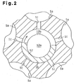
- a plurality of cylinder bores 1a are formed at constant intervals around an axis L of the drive shaft 5.
- Each cylinder bore 1a accommodates a single-headed piston 6 made of an aluminum-based alloy, while permitting the piston 6 to reciprocate.
- a compression chamber 11 is defined that changes in volume depending on reciprocating movement of the piston 6.
- a rotary valve chamber 1b extending in parallel with the axis L of the drive shaft 5 passes through a center of the cylinder block 1.
- the rotary valve chamber 1b receives a rotary valve 12 rotatably in synchronization with the drive shaft 5.
- the rotary valve 12 has an introduction chamber 12a communicating with the suction chamber 4a, and a suction guide groove 12b communicating with the introduction chamber 12a.
- the suction guide groove 12b extends radially.
- the cylinder block 1 has a plurality of radially extending suction passages 1c that connect the compression chamber 11 of each cylinder bore 1a with the introduction chamber 12a via the suction guide groove 12b (see FIG. 2).
- a lug plate 7 made of an iron-base alloy is secured onto the drive shaft 5 in the crank chamber 2a.
- a swash plate 8 made of an iron-base alloy is supported on the drive shaft 5.
- the swash plate 8 slides along and is inclined with respect to the axis L of the drive shaft 5.
- a hinge mechanism K is located between the lug plate 7 and the swash plate 8.
- the hinge mechanism K rotates the swash plate 8 integrally with the lug plate 7 and also guides the slide and the inclination of the swash plate 8 with respect to the axis L of the drive shaft 5.
- the hinge mechanism K includes a pair of guide holes 7b and a pair of guide pins 8b.
- the lug plate 7 has a pair of arms 7a, and each guide hole 7b is formed in one of the arms 7a, respectively.
- the guide pins 8b are fixed to the swash plate 8.
- Each guide pin 8b has, at its tip, a spherical part, which fitted in the corresponding one of the guide holes 7b.
- a through hole 8a passes through a center of the swash plate 8, and the drive shaft 5 is inserted into the through hole 8a. Pairs of hemispherical shoes 9a and 9b made of iron-base alloy are provided on an outer periphery of the swash plate 8.
- each piston 6 is connected to the outer periphery of the swash plate 8 via a pair of the shoes 9a, 9b.
- rotation of the swash plate 8 is converted into reciprocation of the piston 6 depending on inclination angle of the swash plate 8.
- the rear housing member 4 accommodates a control valve 10 connected to the suction chamber 4a, the discharge chamber 4b, and the crank chamber 2a.
- the control valve 10 controls pressure in the crank chamber 2a.
- the inclination angle of the swash plate 8 is changed to control the displacement.
- the compressor includes various first sliding surfaces of first members and various second sliding surfaces of second members that slide upon each other.
- a sliding film is applied to such surfaces as described below.
- the sliding film is formed of coating composition for use in sliding parts which contains a binder resin, a solid lubricant, and inorganic particles mixed with each other, or coating composition for use in sliding parts which contains a binder resin, a solid lubricant, inorganic particles, and a coupling agent mixed with each other.
- the coating composition for use in sliding parts is coated on at least one of the first sliding surfaces and the second sliding surfaces of the compressor, and then heated, to thereby form the sliding film.
- the obtained sliding film contains a solid lubricant and inorganic particles, or a solid lubricant, inorganic particles, and a coupling agent in the cured binder resin.
- the binder resin is employed one having an excellent heat resistance, such as polyimide resin composed of polyamide-imide, polyimide, etc., an epoxy resin or a phenol resin.
- polyimide resin composed of polyamide-imide, polyimide, etc., an epoxy resin or a phenol resin.
- polyamide-imide is optimally used, taking into consideration the cost and the properties as a binder resin.
- the resins in the uncured state are used in the coating composition for use in sliding parts of this invention.
- PTFE polytetrafluoroethylene
- ETFE ethylene tetrafluoroethylene
- FEP tetrafluoroethylene-hexafluoropropylene copolymer
- molybdenum disulfide or graphite.
- the inorganic particles is employed titanium oxide powder, alumina powder, silica powder or silicon carbide powder.
- the inorganic particles are preferably of titanium oxide powder. According to the test results obtained by the inventors, a sliding film using alumina powder, silica powder or silicon carbide powder is good in wear resistance but poor in seizure resistance. On the other hand, a sliding film using titanium oxide powder as inorganic particles is good in wear resistance and seizure resistance. It is considered that the titanium oxide powder has excellent dispersability in the binder resin, produces large effect of providing the sliding film with surface smoothness and preventing the solid lubricant from dropping out of the film, and thus has markedly improved wear resistance. Any of anatase, rutile, or brookite titanium oxide powder may be employed. Rutile titanium oxide powder is optimally used, taking into consideration the degradation of the binder resin by photocatalysis and the cost.
- the average primary particle diameter of titanium oxide powder is 1 ⁇ m or less.
- Titanium oxide powder having an average primary particle diameter of 1 ⁇ m or less has excellent dispersability in the binder resin and produces large effect of providing the sliding film with surface smoothness and preventing the solid lubricant from dropping out of the film.
- titanium oxide powder having an average primary particle diameter of 1 ⁇ m or less makes it possible to constitute an optimum sliding film for a small gap between a first sliding surface of a first member and a second sliding surface of a second member that slide upon each other through the small gap.
- the content of solid lubricant in a binder resin is preferably in the range between 15% by mass to 100% by mass, inclusive, and more preferably in the range between 30% by mass and 80% by mass, inclusive. If the content of solid lubricant in a binder resin is less than 15% by mass, the seizure resistance of the sliding film becomes poor, whereas if the content of solid lubricant in binder resin is more than 100% by mass, the improvement in the seizure resistance of the sliding film becomes small and the solid lubricant becomes apt to drop out of the film, resulting in an increased wear depth of the sliding film.
- the content of inorganic particles is preferably in the range between 5% by mass to 35% by mass, inclusive, and more preferably in the range between 10% by mass and 20% by mass, inclusive. If the content of titanium oxide powder in binder resin is less than 5% by mass, the effect of decreasing the wear depth of the sliding film becomes insufficient, whereas if the content of titanium oxide powder in binder resin is more than 35% by mass, the effect of decreasing the wear depth of the sliding film becomes small.
- the content of coupling agent in the binder resin is preferably in the range between 0.1% by mass and 10% by mass, inclusive, and more preferably in the range between 2% by mass and 8% by mass, inclusive. If the content of coupling agent in binder resin is less than 0.1% by mass, the seizure resistance of the sliding film becomes insufficient, whereas if the content of coupling agent in binder resin is more than 10%, the effect of improving the seizure resistance of the sliding film becomes small.
- Silane coupling agents usable include: for example, vinyltrichlorosilane, vinyltrimethoxysilane, vinyltriethoxysilane, 2-(3,4-epoxycyclohexyl)ethyl trimethoxysilane, 3-glycidoxypropyl trimethoxysilane, 3-glycidoxypropyl methyldiethoxysilane, 3-glycidoxypropyl triethoxysilane, p-styryltrimethoxysilane, 3-methacryloxypropyl methyl dimethoxysilane, 3-methacryloxypropyl trimethoxysilane, 3-methacryloxypropyl methyl diethoxysilane, 3-methacryloxypropyl triethoxysi
- polyamide-imide When polyamide-imide is employed as the binder resin, it is preferable to employ, as the silane coupling agent, 2-(3,4-epoxycyclohexyl)ethyl trimethoxysilane, 3-triethoxysilyl-N-(1,3-dimethyl-butylidene)propylamine, N-phenyl-3-aminopropyl trimethoxysilane, 3-ureidopropyl triethoxysilane and/or 3-isocyanatopropyl triethoxysilane.
- silane coupling agent 2-(3,4-epoxycyclohexyl)ethyl trimethoxysilane, 3-triethoxysilyl-N-(1,3-dimethyl-butylidene)propylamine, N-phenyl-3-aminopropyl trimethoxysilane, 3-ureidopropyl triethoxysilane and/or 3-isocyan
- 2-(3,4-epoxycyclohexyl)ethyl trimethoxysilane which has an epoxy group as a functional group
- 3-glycidoxypropyl trimethoxysilane 3-glycidoxypropyl methyldiethoxysilane
- 3-glycidoxypropyl triethoxysilane are also excellent in storage stability.
- the swash plate 8 is selected as the first member, and the shoes 9a and 9b are selected as the second members.
- sliding films C31 shown in below described Table 3 are applied to a front surface 8c and a rear surface 8d (first sliding surfaces) of the swash plate 8 on which flat surfaces 9c and 9d (second sliding surfaces) of the shoes 9a and 9b slide.
- the sliding films C31 are formed as follows.
- a degreased swash plate 8 made of an iron-base alloy is prepared, and the coating composition for use in sliding parts is coated on a front surface 8c and a rear surface 8d on an outer periphery of the swash plate 8.
- the coating composition for use in sliding parts is coated on the swash plate 8 by roll coat transferring, and the swash plate 8 is heated at 200°C for 60 minutes under the atmospheric conditions to cure the uncured binder resin.
- the sliding film C31 formed of binder resin which contains a solid lubricant, inorganic particles, and a silane coupling agent is formed on the front surface 8c and the rear surface 8d on the outer periphery of the swash plate 8.
- the solid lubricant and the inorganic particles are dispersed in the binder resin to form the sliding films C31.
- the obtained swash plate 8 is used to assemble the compressor.
- the coating composition for use in sliding parts may also be coated on the surfaces 8c and 8d of the swash plate 8 by air spraying.
- a pulley or an electromagnetic clutch is connected to the drive shaft 5 of the compressor, and the compressor is mounted to a vehicle.
- the pulley or the electromagnetic clutch is driven by an engine via a belt.
- Rotation of the drive shaft 5 by the engine causes the swash plate 8 to wobble, and causes each piston 6 to reciprocate within the corresponding cylinder bore 1a with a stroke depending on inclination angles of the swash plate 8.
- the rotation of the drive shaft 5 causes the rotary valve 12 to rotate, and the introduction chamber 12a selectively communicates with or shut off the corresponding compression chamber 11 in synchronization with each piston 6 via the suction guide groove 12b and the corresponding suction passage 1c.
- the rotary valve 12 provides communication between the introduction chamber 12a and the compression chamber 11, and a refrigerant gas in the evaporator is drawn into the compression chamber 11 via the suction chamber 4a and the introduction chamber 12a.
- the rotary valve 12 blocks communication between the introduction chamber 12a and the compression chamber 11, and the refrigerant gas is compressed in the compression chamber 11 and then discharged to the condenser via the discharge chamber 4b.
- the solid lubricant contained in the sliding films C31 applied to the surfaces 8c and 8d of the swash plate 8 secure seizure resistance between the swash plate 8 and the shoes 9a and 9b like a conventional compressor.
- the inorganic particles contained in the sliding film C31 support a load acting between the swash plate 8 and the shoes 9a and 9b.
- the silane coupling agent contained in the sliding film C31 serves to bind the solid lubricant and the inorganic particles firmly to the binder resin. This prevents the solid lubricant from dropping out of the film, resulting in reduced wear depth of the sliding film C31 and reduced rattles of the compressor.
- the sliding films C31 on the surfaces 8c and 8d of the swash plate 8 allow the flat surfaces 9c and 9d of the shoes 9a and 9b to slide smoothly. This prevents rattles of the swash plate 8 and the shoes 9a and 9b by wear of at least one of them or failures resulting from seizure therebetween more effectively than the conventional compressor.
- any of other sliding films C2 to C19, C29, C30, C32 to C36 shown in below described Tables 1 to 4 may be formed on the surfaces 8c and 8d of the swash plate 8.
- similar sliding films may be formed on the flat surfaces 9c and 9d of the shoes 9a and 9b only. Also, similar sliding films may be formed on the surfaces 8c and 8d of the swash plate 8 and the flat surfaces 9c and 9d of the shoes 9a and 9b.
- the shoes 9a and 9b may be selected as s first member, and the piston 6 may be selected as second members.
- similar sliding films C31 may be formed on at least one of convex spherical surfaces 9e and 9f of the shoes 9a and 9b as first sliding surfaces and concave spherical surfaces 6a of the piston 6 as second sliding surfaces.
- the sliding films C31 allow each other to slide smoothly, thus preventing rattles of the shoes 9a and 9b and the piston 6 by wear of at least one of them or failures resulting from seizure therebetween more effectively than the conventional compressor.
- the convex spherical surfaces 9e and 9f of the shoes 9a and 9b slide smoothly upon the concave spherical surfaces 6a of the piston 6, and the flat surfaces 9c and 9d of the shoes 9a and 9b readily follow the surfaces 8c and 8d of the swash plate 8, thus preventing rattles of the swash plate 8 and the shoes 9a and 9b by wear of at least one of them or failures resulting from seizure therebetween more effectively than the conventional compressor.
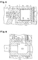
- the piston 6 may be selected as a first member, and the cylinder block 1 that is a part of the housing may be selected as a second member.
- a similar sliding film C31 may be formed on at least one of a circumferential surface 6b of the piston 6 as a first sliding surface, and an inner circumferential surface of the cylinder bore 1a of the cylinder block 1 as a second sliding surface.
- the sliding film C31 allows each other to smoothly slide, thus preventing rattles of the piston 6 and the cylinder block 1 by wear of at least one of them or failures resulting from seizure therebetween more effectively than the conventional compressor.
- the cylinder block 1, which is part of the housing may be selected as a first member, and the rotary valve 12 may be selected as a second member.
- a similar sliding film C31 may be formed on at least one of an inner circumferential surface of the rotary valve chamber 1b of the cylinder block 1 as a first sliding surface, and an outer circumferential surface of the rotary valve 12 as a second sliding surface.
- the sliding film C31 allows each other to smoothly slide, thus preventing rattles of the cylinder block 1 and the rotary valve 12 by wear of at least one of them or failures resulting from seizure therebetween more effectively than the conventional compressor.
- a similar sliding film may be applied to at least one of an inner circumferential surface of a shaft hole of the front housing member 2 and an outer circumferential surface of the drive shaft 5 to slidably and rotatably support the drive shaft 5 by the front housing member 2, without using the radial bearing 2b.
- a similar sliding film may be applied to at least one of an inner end surface of the front housing member 2 and a front end surface of the lug plate 7 to slidably and rotatably support the lug plate 7 by the front housing member 2, without using a thrust bearing 2c.
- a similar sliding film may be applied to at least one of an inner circumferential surface of the through hole 8a of the swash plate 8 and the outer circumferential surface of the drive shaft 5 to allow the swash plate 8 and the drive shaft 5 to smoothly slide upon each other. Further, a similar sliding film may be applied to at least one of an the inner circumferential surface of each guide hole 7b of the lug plate 7 and the outer surface of the spherical part of each guide pin 8b of the swash plate 8 to allow the spherical part of the guide pin 8b to smoothly slide in the guide hole 7b.
- a similar sliding film may be applied to at least one of a rear end surface 12c of the rotary valve 12 and a front end surface 4c of the rear housing member 4, which is part of the housing and slides upon the rear end surface 12c, to allow the rear end surface 12c of the rotary valve 12 to smoothly slide upon the front end surface 4c of the rear housing member 4, that is, the housing.
- the piston 6 may be selected as a first member, and the front housing member 2 that is a part of the housing may be selected as a second member.
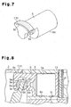
- the piston 6 has a rotation restrictor 6c (a first sliding surface) that prevents rotation of the piston 6 caused by the rotation of the swash plate 8.
- the rotation restrictor 6c slides upon an inner circumferential surface (a second sliding surface) of the front housing member 2 by reciprocation of the piston 6, and a similar sliding film C31 may be applied to at least one of the rotation restrictor 6c of the piston 6 and the inner circumferential surface of the front housing member 2 to allow the rotation restrictor 6c of the piston 6 to smoothly slide upon the inner circumferential surface of the front housing member 2, that is, the housing.
- a fixed displacement swash plate type compressor includes a pair of cylinder block members 21a and 21b made of an aluminum-based alloy, a front housing member 22 made of an aluminum-based alloy and secured to a front end of the cylinder block member 21a with a valve mechanism 23a including a valve plate, a discharge valve, and a retainer, and a rear housing member 24 made of an aluminum-based alloy and secured to a rear end of the cylinder block member 21b with a valve mechanism 23b including a valve plate, a discharge valve, and a retainer.
- a discharge chamber 22b is defined in the front housing member 22.
- a suction chamber 24a and a discharge chamber 24b are formed in the rear housing member 24.
- the cylinder block members 21a and 21b, the front housing member 22, and the rear housing member 24 constitute the housing.
- the discharge chambers 22b and 24b communicate with a single discharge chamber (not show).
- the suction chamber 24a is connected to an evaporator (not show), the evaporator is connected to a condenser (not show) via an expansion valve (not show), and the condenser is connected to the discharge chamber.
- a drive shaft 25 made of an iron-base alloy is slidably and rotatably supported.
- a seal member 22a is provided between the drive shaft 25 and the front housing member 22.
- a plurality of cylinder bores 21d and 21e (only one of each is shown in FIG. 9) extending in parallel with an axis L of the drive shaft 25 pass through the cylinder block members 21a and 21b.
- Each pair of cylinder bores 21d and 21e accommodate a doubleheaded piston 26 made of an aluminum-based alloy to permit the piston 26 to reciprocate.
- compression chambers 31 are defined in each pair of the cylinder bores 21d and 21e.
- the compression chambers 31 are changed in volume depending on reciprocation of the piston 26.
- the drive shaft 25 has an introduction chamber 25a communicating with the suction chambers 24a.
- Suction guide grooves 25b radially pass through a front end and a rear end of the introduction chamber 25a.
- Suction passages 21f that provide communication between each of the cylinder bores 21d and 21e and the introduction chamber 25a via the suction guide grooves 25b passes through each of the cylinder block members 21a and 21b.
- a swash plate chamber 21c is defined between the cylinder block members 21a and 21b.
- a swash plate 28 made of an aluminum-based alloy is secured to the drive shaft 25.
- Pairs of hemispherical shoes 29a, 29b made of an aluminum-based alloy are provided on an outer periphery of the swash plate 28.
- Each piston 26 is engaged with the outer periphery of the swash plate 28 via the shoes 29a and 29b.
- Thrust bearings 27 are provided between opposite end surfaces of the swash plate 28 and inner surfaces of corresponding cylinder block members 21a and 21b. The swash plate 28 is held between the cylinder block members 21a and 21b via the pair of thrust bearings 27.
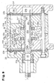
- the cylinder block members 21a and 21b which are part of the housing, are selected as a first member, and the drive shaft 25 is selected as a second member.
- sliding films C31 shown in Table 3 is applied to an outer circumferential surface 25c (a second sliding surface) of the drive shaft 25 on which inner circumferential surfaces 21h and 21g (a first sliding surface) of the cylinder block members 21a and 21b slide.
- the sliding films C31 are formed as follows.
- a coating composition for use in sliding parts and the drive shaft 25 are prepared, and the coating composition for use in sliding parts is coated on the outer circumferential surface 25c of the drive shaft 25.
- the coating composition for use in sliding parts is coated on the drive shaft 25 by roll coat transferring, and the drive shaft 25 is heated at 200°C for 60 minutes under the atmospheric conditions to cure uncured binder resin.
- the sliding films C31 formed of binder resin which contains a solid lubricant, inorganic particles, and a silane coupling agent are applied to the outer circumferential surface 25c of the drive shaft 25.
- the solid lubricant and the inorganic particles are dispersed in the binder resin to form the sliding films C31.
- the obtained drive shaft 25 is used to assemble the compressor.
- a pulley or electromagnetic clutch (neither is shown) is connected to the drive shaft 25 of the compressor thus configured, and the compressor is mounted to a vehicle (not show).
- the pulley or the electromagnetic clutch is driven by an engine via a belt (not show).
- Rotation of the drive shaft 25 while the engine is driven causes the swash plate 28 to wobble, and causes the pistons 26 to reciprocate within the cylinder bores 21d and 21e with a stroke depending on inclination angles of the swash plate 28.
- the rotation of the drive shaft 25 causes the introduction chamber 25a to selectively communicate with or shut off the compression chambers 31 via the suction guide groove 25b and the suction passages 21f. For example, when each piston 26 moves from the right to the left in FIG.
- the introduction chamber 25a communicates with the compression chamber 31 on the right.
- a refrigerant gas in the evaporator in a refrigeration circuit is drawn into the compression chamber 31 on the right via the suction chamber 24a and the introduction chamber 25a.
- communication between the compression chamber 31 on the left and the introduction chamber 25a is blocked, and the refrigerant gas is compressed in the compression chamber 31 on the left and then discharged to the condenser via the discharge chamber 24b.
- the compression chamber 31 operates in an opposite manner.
- the solid lubricant contained in the sliding film C31 applied to the outer circumferential surface 25c of the drive shaft 25 secures seizure resistance between the drive shaft 25 and the inner circumferential surfaces 21g and 21h of the cylinder block members 21a and 21b.
- the inorganic particles contained in the sliding film C31 support a load acting between the drive shaft 25 and the inner circumferential surfaces 21g and 21h of the cylinder block members 21a and 21b.
- the silane coupling agent contained in the sliding film C31 serves to bind the solid lubricant and the inorganic particles firmly to the binder resin. This prevents the solid lubricant from dropping out of the film, resulting in reduced wear depth of the sliding film C31 and reduced rattles of the compressor.
- the sliding films C31 allow the outer circumferential surface 25c of the drive shaft 25 to smoothly slide. This prevents rattles of the drive shaft 25 and the cylinder block members 21a and 21b by wear of at least one of them or failures resulting from seizure therebetween more effectively than the conventional compressor.
- any of sliding films C2 to C19, C29, C30, C32 to C36 shown in below described Tables 1 to 4 may be formed on the outer circumferential surface 25c of the drive shaft 25.
- a similar sliding films may be formed only on the inner circumferential surfaces 21g and 21h of the cylinder block members 21a and 21b. Also, a similar sliding films may be formed on the outer circumferential surface 25c of the drive shaft 25 and the inner circumferential surfaces 21g and 21h of the cylinder block members 21a and 21b.
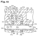
- the swash plate 28 may be selected as a first member, and the shoes 29a and 29b may be selected as a second member.
- a similar sliding film may be formed on at least one of surfaces 28c and 28d (a first sliding surface) of the swash plate 28 and flat surfaces 29c and 29d (a second sliding surface) of the shoes 29a and 29b.
- the sliding film allows each other to smoothly slide, thus preventing rattles of the swash plate 28 and the shoes 29a and 29b by wear of at least one of them or failures resulting from seizure therebetween more effectively than the conventional compressor.
- the shoes 29a and 29b may be selected as first members, and the pistons 26 may be selected as second members.
- similar sliding film may be formed on at least one of convex spherical surfaces 29e and 29f (a first sliding surface) of the shoes 29a and 29b and concave spherical surfaces 26a (a second sliding surface) of the pistons 26.
- the sliding films allow each other to smoothly slide, thus preventing rattles of the shoes 29a and 29b and the piston 26 by wear of at least one of them or failures resulting from seizure therebetween more effectively than the conventional compressor.
- the convex spherical surfaces 29e and 29f of the shoes 29a and 29b smoothly slide upon the concave spherical surfaces 26a of the piston 26, and the flat surfaces 29c and 29d of the shoes 29a and 29b smoothly follows the surfaces 28c and 28d of the swash plate 28, thus preventing rattles of the swash plate 28 and the shoes 29a and 29b by wear of at least one of them or failures resulting from seizure therebetween more effectively than the conventional compressor.
- the pistons 26 may be selected as first members, and the cylinder block members 21a and 21b may be selected as second members.
- similar sliding films may be formed on at least one of a circumferential surface 26b (a first sliding surface) of the piston 26, and inner circumferential surfaces (a second sliding surface) of the cylinder bores 21e and 21d of the cylinder block members 21a and 21b.
- the sliding films allow each other to smoothly slide, thus preventing rattles of the piston 26 and the cylinder block members 21a and 21b by wear of at least one of them or failures resulting from seizure therebetween more effectively than the conventional compressor.
- Similar sliding films may be applied to at least one of opposite end surfaces 28e and 28f of the swash plate 28 and wall surfaces 21i and 21j forming the swash plate chamber 21c of the cylinder block members 21a and 21b, without using the thrust bearing 27.
- This configuration allows the swash plate 28 to be slidably and rotatably held between the cylinder block members 21a and 21b.
- the pistons 26 may be selected as first members, and the swash plate 28 may be selected as a second member.
- similar sliding films may be formed on at least one of a rotation restrictor 26c (a first sliding surface) of the piston 26, and an outer circumferential surface 28g (a second sliding surface) of the swash plate 28.
- the sliding films allow each other to smoothly slide, thus preventing rattles of the rotation restrictor 26c of the piston 26 and the outer circumferential surface 28g of the swash plate 28 by wear of at least one of them or failures resulting from seizure therebetween more effectively than the conventional compressor.
- PAI resin varnish was blended with a solid lubricant (PTFE, MoS2, etc.), titanium oxide powder and a coupling agent, fully stirred and passed through a triple roll mill to prepare a coating composition for use in sliding parts.
- the coating composition for use in sliding parts was optionally diluted with n-methyl-2-pyrrolidone or xylene, as a solvent, or the mixed solvent thereof depending on the types of coating methods employed (spray coating, roll coating, etc.) for the purpose of adjustment of viscosity, solid material concentration, etc.
- the coating composition for use in sliding parts may also be prepared in such a manner as to first blend a solid lubricant and titanium oxide powder with a coupling agent to prepare a treated powder and then mix the treated powder with PAI resin varnish.
- the solid lubricant and the titanium oxide powder are readily dispersed in the PAI resin varnish, hard to maldistribute in a sliding film formed of the coating composition for use in sliding parts and bound securely to the binder resin via the coup
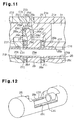
- degreased ingot of aluminum alloy A390 was prepared and a plurality of substrates 91, as first members, with its section perpendicular to the axis having C-like shape and its length 20 mm were formed as shown in FIG. 13.
- substrates two were selected and combined so that they faced each other to form a bush 20 mm in inside diameter.
- Coating compositions for use in sliding parts having been prepared so that sliding films C1 to C37 had the respective compositions shown in Table 1 to Table 4 were coated on the inside surface 1a of the respective substrates 91 by air spraying to form coating films 25 ⁇ m thick.
- Table 1 to Table 4 also show the amount % by mass of each solid lubricant, inorganic particles or silane coupling agent per 100 mass % of PAI resin. Coating can also be carried out by roll coat transferring, instead of air spraying.
- the substrates 91 each having a coating formed on their inside surface were heated at 200°C for 60 minutes under the atmospheric conditions to cure the PAI resin. Thus sliding films C1 to C37 were applied onto the respective substrates 91.
- a plurality of substrates 93 were prepared by cutting the above described ingot to 30 mm long, 30 mm wide and 5 mm thick, as shown in FIG. 14.
- the surfaces 93a of the substrates 93 were coated, by air spraying, with the respective coating compositions for use in sliding parts C1 to C37 that had been prepared to have the compositions shown in Table 1 to Table 4 to form coating films 25 ⁇ m thick.
- Coating can also be carried out by roll coat transferring, instead of air spraying.
- the substrates 93 each having a coating formed on their inside surface were heated at 200°C for 60 minutes under the atmospheric conditions to cure the PAI resin.
- sliding films C1 to C37 were applied onto the respective substrates 93.
- the surface roughness (Rz) of each of the sliding films C21 to C28 was measured.
- the wear depth ( ⁇ m) was obtained with a journal bearing
- the wear depth ( ⁇ m) was obtained with a journal bearing tester shown in FIG. 13.
- a shaft 92, as a second member, which was made up of carbon steel (S55C) and 20 mm in diameter was inserted into and passed through a bush consisting of a pair of substrates 91.
- the measurement was carried out while setting a load from the bush at 1000 N, testing time at 1 hour and the number of revolutions of the shaft 92 against the bush at 5000 rpm (5.2 m/sec) and constantly supplying lubricating oil between the bush and the shaft 92.
- the seizure specific pressure was obtained with a thrust-type tester shown in FIG. 14.
- a cylindrical member 94 as a second member, which was made up of spring steel (SUJ2) was rotated on the surface 93a (a first sliding surface) of each substrate 93.
- the load at a time when seizure occurred between the surface 93a of each substrate 93 and the surface (a second sliding surface) of the cylindrical member 94 that was opposite to the surface 93a was obtained while rotating the cylindrical member 94 at a rotational speed to increase 1.2 m/sec on a fixed cycle (1 MPa/2 mins), that is, to increase the load applied from the cylindrical member 94 to the substrate 93.
- the kinetic coefficient of friction was also measured for each substrate 93 right after and 100 hours after starting the test under the conditions: a sliding speed of 1.2 m/sec and a specific pressure of 9.8 MPa. For the sliding films of C1 to C20 and C29 to C37, the kinetic coefficient of friction was not measured. The results are shown in Table 5 to Table 7.
- the data on the sliding films C1 to C4 and C20 shown in Table 5 and C37 shown in Table 7 indicate that when a sliding film is formed of a binder resin which contains a solid lubricant and in which part of the solid lubricant is replaced with titanium oxide powder, it has not satisfactorily improved wear resistance and seizure resistance.
- the data on the sliding films C1, C5 to C7, and C20 shown in Table 5 and C37 shown in Table 7 indicate that when a sliding film is formed of binder resin which contains solid lubricant and in which part of the solid lubricant is replaced with a silane coupling agent, it has not satisfactorily improved wear resistance and seizure resistance.
- the data on the sliding films C1, C8 to C10, and C20 shown in Table 5 and C37 shown in Table 7 indicate that when a sliding film is formed of binder resin which contains solid lubricant, titanium oxide powder and a silane coupling agent, it particularly improves wear resistance and seizure resistance.
- the data on the sliding films C11 to C19 shown in Table 5, C30 shown in Table 6, and C31 to C36 in Table 7 indicate that when a sliding film is formed of binder resin which contains solid lubricant, titanium oxide powder and a silane coupling agent, if the percentage of the silane coupling agent to the PAI resin is in the range between 0.1% by mass to 10% by mass, inclusive, centered at 3% by mass, it particularly improves wear resistance and seizure resistance.
- the data on the sliding films C14 and C15 shown in Table 5 indicate that even if the amount of the binder resin is decreased compared with that of the sliding films C12 and C13, as long as films contain titanium oxide powder and a silane coupling agent, their wear resistance is excellent and their seizure resistance does not significantly deteriorate.
- the data on the sliding films C9 and C16 to C19 shown in Table 5 and C34 to C36 shown in Table 7 indicate that as long as the silane coupling agent is 2-(3,4-epoxycyclohexyl)ethyl trimethoxysilane, 3-triethoxysilyl-N-(1,3-dimethylbutylidene)propylamine, N-phenyl-3-aminopropyl trimethoxysilane, 3-ureidopropyl triethoxysilane, 3-isocyanatopropyl triethoxysilane, 3-glycidoxypropyl trimethoxysilane, 3-glycidoxypropyl methyldiethoxysilane, or 3-glycidoxypropyl triethoxysilane, sliding films all have excellent wear resistance and seizure resistance.
- the data on the sliding film C20 shown in Table 5, C21 to C25 shown in Table 6, and C37 shown in Table 7 indicate that the sliding films formed of coating composition for use in sliding parts that contains titanium oxide powder is more excellent in wear resistance than those formed of coating composition for use in sliding parts that does not contain titanium oxide powder.
- the sliding films in which the content of titanium oxide powder in PAI resin is more than 35% by mass are less effective in decreasing wear depth.
- the data on the sliding film C20 shown in Table 5, C23, C26 and C27 shown in Table 6, and C37 shown in Table 7 indicate that the sliding films formed of coating compositions for use in sliding parts that contains inorganic particles is more excellent in wear resistance than those formed of coating compositions for use in sliding parts that do not contain inorganic particles; however, the sliding films using silicon carbide powder or silica powder as inorganic particles are good in wear resistance to some extent, but poor in seizure resistance. The same is true for the sliding films using alumina powder. In contrast, the sliding films using titanium oxide powder are good in both wear resistance and seizure resistance.
- titanium oxide powder having an average primary particle diameter of 0.3 ⁇ m is used in the tests, even if titanium oxide powder has an average primary particle diameter of less than 0.3 ⁇ m or more than 0.3 ⁇ m, as long as it has an average diameter of 1 ⁇ m or less, the titanium oxide powder has excellent dispersability in the binder resin and exerts excellent effect of preventing solid lubricant from dropping out of the films, whereby it can provide markedly improved wear resistance.
- a compressor includes a swash plate, and a shoe connected to an outer periphery of the swash plate. A surface of the swash plate slides upon a flat surface of the shoe. A sliding film is applied to the surface of the swash plate. The sliding film is formed of binder resin which contains a solid lubricant and titanium oxide powder. This allows the surface of the swash plate and the flat surface of the shoe to smoothly slide upon each other.
Abstract
The sliding film is formed of binder resin which contains a solid lubricant and titanium oxide powder. This allows the surface of the swash plate and the flat surface of the shoe to smoothly slide upon each other.
Description
- The present invention relates to a compressor.
- Japanese Laid-Open Patent Publication No. 2002-89437, for example, discloses a compressor having a housing in which a plurality of cylinder bores, a crank chamber, a suction chamber, and a discharge chamber are formed. The compressor is incorporated into a refrigeration circuit including an evaporator, a suction device, and a condenser. Each cylinder bore of the compressor accommodates a corresponding piston, while permitting the piston to reciprocate. A drive shaft rotatably supported by the housing is driven by an external drive source such as an engine. A swash plate is supported on the drive shaft rotatably in synchronization therewith. The swash plate is connected to the piston with pairs of hemispherical shoes. A sliding film is formed on a surface of the swash plate that slides upon a flat surface of the shoes. The sliding film is formed of a binder resin which contains a solid lubricant such as molybdenum disulfide.
- When the drive shaft is driven by the external drive source, the swash plate rotates in synchronization therewith to cause the piston to reciprocate within the cylinder bore via the shoes. In each cylinder bore, a compression chamber is defined that changes in volume depending on reciprocating movement of a piston head. When the piston moves from the top dead center to the bottom dead center, a low pressure refrigerant gas is drawn into the compression chamber from the suction device connected to the evaporator in the refrigeration circuit. On the other hand, when the piston moves from the bottom dead center to the top dead center, a high pressure refrigerant gas is discharged into the discharge chamber from the compression chamber. The discharge chamber is connected to the condenser in the refrigeration circuit. The refrigeration circuit is used for air conditioning of a vehicle as an air conditioning system for a vehicle.
- For this compressor, the sliding film applied to the surface of the swash plate allows the flat surface of the shoe to smoothly slide, thus preventing rattles of the swash plate and the shoes by wear of at least one of them or failures resulting from seizure therebetween.
- In the conventional compressor, further improved sliding properties are desired under severe conditions such as where not only the surface of the swash plate and the flat surface of the_shoes, but also a first sliding surface of a first member and a second sliding surface of a second member slide upon each other at high speed or under a relatively heavy load such as a high heat load. Thus, it can be considered to increase the content of solid lubricant, for example, to increase the content of molybdenum disulfide in the sliding film to 10% by mass or more and thereby improve seizure resistance between the first member and the second member. However, if the content of solid lubricant is increased, the solid lubricant will be apt to drop out of the film, resulting in increased wear depth of the sliding film.
- An object of the invention is to provide a compressor having good sliding properties.
- In order to achieve the above described object, the present invention provides a compressor having a first a first member having a first sliding surface, and a second member having a second sliding surface. One of the sliding surfaces slides on the other sliding surface. A sliding film made of a binder resin is formed on at least one of the first sliding surface and the second sliding surface. The binder resin contains at least solid lubricant and inorganic particles.
- Other aspects and advantages of the invention will become apparent from the following description, taken in conjunction with the accompanying drawings, illustrating by way of example the principles of the invention.
- The invention, together with objects and advantages thereof, may best be understood by reference to the following description of the presently preferred embodiments together with the accompanying drawings in which:
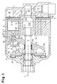
- FIG. 1 is a cross-sectional view of a compressor according to a first embodiment of the present invention;
- FIG. 2 is a cross-sectional view taken along line II-II;
- FIG. 3 is a cross-sectional view including sliding surfaces between shoes and a swash plate provided in the compressor in FIG. 1;
- FIG. 4 is a cross-sectional view including sliding surfaces between shoes and a piston in a modified embodiment of the compressor in FIG. 1;
- FIG. 5 is a cross-sectional view including a sliding surface between a piston and a housing in a modified embodiment of the compressor in FIG. 1;
- FIG. 6 is a cross-sectional view including a sliding surface between a rotary valve and a housing in a modified embodiment of the compressor in FIG. 1;
- FIG. 7 is a perspective view of a piston in a modified embodiment of the compressor in FIG. 1;
- FIG. 8 is a cross-sectional view including a sliding surface between a rotation restrictor of a piston and a housing in a modified embodiment of the compressor in FIG. 1;
- FIG. 9 is a cross-sectional view of a compressor according to a second embodiment of the invention;
- FIG. 10 is a cross-sectional view including a sliding surface between a drive shaft and a housing provided in the compressor in FIG. 9;
- FIG. 11 is a cross-sectional view including a sliding surface between a piston and a swash plate provided in the compressor in FIG. 9;
- FIG. 12 is a perspective view of the piston provided in the compressor in FIG. 9;
- FIG. 13 is a perspective view of a journal bearing tester; and
- FIG. 14 is a perspective view of a thrust-type tester.
-
- Now, a first embodiment of the invention will be described with reference to FIGS. 1 to 8.
- As shown in FIG. 1, a variable displacement swash plate type compressor includes a
cylinder block 1 made of an aluminum-based alloy, afront housing member 2 made of an aluminum-based alloy and secured to a front end of thecylinder block 1, and a rear housing member 4 made of an aluminum-based alloy and secured to a rear end of thecylinder block 1 via a valve mechanism 3 including a valve plate, a discharge valve, and a retainer. Acrank chamber 2a is defined between thecylinder block 1 and thefront housing member 2. Asuction chamber 4a and adischarge chamber 4b are defined in the rear housing member 4. In this embodiment, thecylinder block 1, thefront housing member 2, and the rear housing member 4 constitute the housing. Thesuction chamber 4a is connected to an evaporator (not show), the evaporator is connected to a condenser (not show) via an expansion valve (not show), and the condenser is connected to thedischarge chamber 4b. The compressor, the evaporator, the expansion valve, and the condenser constitute an air conditioning refrigeration circuit for a vehicle. In the drawings, the left is the front side, and the right is the rear side. - In the
front housing member 2, adrive shaft 5 made of an iron-base alloy is rotatably supported via a radial bearing 2b. As shown in FIG. 2, a plurality ofcylinder bores 1a (only one is shown in FIG. 1) are formed at constant intervals around an axis L of thedrive shaft 5. Eachcylinder bore 1a accommodates a single-headed piston 6 made of an aluminum-based alloy, while permitting thepiston 6 to reciprocate. In eachcylinder bore 1a, acompression chamber 11 is defined that changes in volume depending on reciprocating movement of thepiston 6. As shown in FIG. 1, arotary valve chamber 1b extending in parallel with the axis L of thedrive shaft 5 passes through a center of thecylinder block 1. Therotary valve chamber 1b receives arotary valve 12 rotatably in synchronization with thedrive shaft 5. Therotary valve 12 has anintroduction chamber 12a communicating with thesuction chamber 4a, and asuction guide groove 12b communicating with theintroduction chamber 12a. Thesuction guide groove 12b extends radially. Thecylinder block 1 has a plurality of radially extendingsuction passages 1c that connect thecompression chamber 11 of eachcylinder bore 1a with theintroduction chamber 12a via thesuction guide groove 12b (see FIG. 2). - A lug plate 7 made of an iron-base alloy is secured onto the
drive shaft 5 in thecrank chamber 2a. Aswash plate 8 made of an iron-base alloy is supported on thedrive shaft 5. Theswash plate 8 slides along and is inclined with respect to the axis L of thedrive shaft 5. A hinge mechanism K is located between the lug plate 7 and theswash plate 8. Thus, theswash plate 8 is connected to the lug plate 7 via the hinge mechanism K. The hinge mechanism K rotates theswash plate 8 integrally with the lug plate 7 and also guides the slide and the inclination of theswash plate 8 with respect to the axis L of thedrive shaft 5. - The hinge mechanism K includes a pair of guide holes 7b and a pair of
guide pins 8b. The lug plate 7 has a pair ofarms 7a, and each guide hole 7b is formed in one of thearms 7a, respectively. The guide pins 8b are fixed to theswash plate 8. Eachguide pin 8b has, at its tip, a spherical part, which fitted in the corresponding one of the guide holes 7b. A through hole 8a passes through a center of theswash plate 8, and thedrive shaft 5 is inserted into the through hole 8a. Pairs ofhemispherical shoes swash plate 8. An end of eachpiston 6 is connected to the outer periphery of theswash plate 8 via a pair of theshoes swash plate 8 is converted into reciprocation of thepiston 6 depending on inclination angle of theswash plate 8. - The rear housing member 4 accommodates a
control valve 10 connected to thesuction chamber 4a, thedischarge chamber 4b, and thecrank chamber 2a. Thecontrol valve 10 controls pressure in thecrank chamber 2a. Depending on the pressure control, the inclination angle of theswash plate 8 is changed to control the displacement. - The compressor includes various first sliding surfaces of first members and various second sliding surfaces of second members that slide upon each other. A sliding film is applied to such surfaces as described below.
- The sliding film is formed of coating composition for use in sliding parts which contains a binder resin, a solid lubricant, and inorganic particles mixed with each other, or coating composition for use in sliding parts which contains a binder resin, a solid lubricant, inorganic particles, and a coupling agent mixed with each other. The coating composition for use in sliding parts is coated on at least one of the first sliding surfaces and the second sliding surfaces of the compressor, and then heated, to thereby form the sliding film. The obtained sliding film contains a solid lubricant and inorganic particles, or a solid lubricant, inorganic particles, and a coupling agent in the cured binder resin.
- As the binder resin, is employed one having an excellent heat resistance, such as polyimide resin composed of polyamide-imide, polyimide, etc., an epoxy resin or a phenol resin. Of the above resins, polyamide-imide is optimally used, taking into consideration the cost and the properties as a binder resin. The resins in the uncured state are used in the coating composition for use in sliding parts of this invention.
- As the solid lubricant, is employed polytetrafluoroethylene (PTFE), ethylene tetrafluoroethylene (ETFE), tetrafluoroethylene-hexafluoropropylene copolymer (FEP), molybdenum disulfide, or graphite.
- As the inorganic particles, is employed titanium oxide powder, alumina powder, silica powder or silicon carbide powder. The inorganic particles are preferably of titanium oxide powder. According to the test results obtained by the inventors, a sliding film using alumina powder, silica powder or silicon carbide powder is good in wear resistance but poor in seizure resistance. On the other hand, a sliding film using titanium oxide powder as inorganic particles is good in wear resistance and seizure resistance. It is considered that the titanium oxide powder has excellent dispersability in the binder resin, produces large effect of providing the sliding film with surface smoothness and preventing the solid lubricant from dropping out of the film, and thus has markedly improved wear resistance. Any of anatase, rutile, or brookite titanium oxide powder may be employed. Rutile titanium oxide powder is optimally used, taking into consideration the degradation of the binder resin by photocatalysis and the cost.
- Preferably the average primary particle diameter of titanium oxide powder is 1 µm or less. Titanium oxide powder having an average primary particle diameter of 1 µm or less has excellent dispersability in the binder resin and produces large effect of providing the sliding film with surface smoothness and preventing the solid lubricant from dropping out of the film. Further, titanium oxide powder having an average primary particle diameter of 1 µm or less makes it possible to constitute an optimum sliding film for a small gap between a first sliding surface of a first member and a second sliding surface of a second member that slide upon each other through the small gap.
- In the sliding film, the content of solid lubricant in a binder resin is preferably in the range between 15% by mass to 100% by mass, inclusive, and more preferably in the range between 30% by mass and 80% by mass, inclusive. If the content of solid lubricant in a binder resin is less than 15% by mass, the seizure resistance of the sliding film becomes poor, whereas if the content of solid lubricant in binder resin is more than 100% by mass, the improvement in the seizure resistance of the sliding film becomes small and the solid lubricant becomes apt to drop out of the film, resulting in an increased wear depth of the sliding film.
- In the sliding film, the content of inorganic particles is preferably in the range between 5% by mass to 35% by mass, inclusive, and more preferably in the range between 10% by mass and 20% by mass, inclusive. If the content of titanium oxide powder in binder resin is less than 5% by mass, the effect of decreasing the wear depth of the sliding film becomes insufficient, whereas if the content of titanium oxide powder in binder resin is more than 35% by mass, the effect of decreasing the wear depth of the sliding film becomes small.
- Further, in the sliding film, the content of coupling agent in the binder resin is preferably in the range between 0.1% by mass and 10% by mass, inclusive, and more preferably in the range between 2% by mass and 8% by mass, inclusive. If the content of coupling agent in binder resin is less than 0.1% by mass, the seizure resistance of the sliding film becomes insufficient, whereas if the content of coupling agent in binder resin is more than 10%, the effect of improving the seizure resistance of the sliding film becomes small.
- As the coupling agent, is employed a silane coupling agent, a titanate coupling agent, or an aluminate coupling agent. According to the test results obtained by the inventors, it is preferable to employ a silane coupling agent. Silane coupling agents usable include: for example, vinyltrichlorosilane, vinyltrimethoxysilane, vinyltriethoxysilane, 2-(3,4-epoxycyclohexyl)ethyl trimethoxysilane, 3-glycidoxypropyl trimethoxysilane, 3-glycidoxypropyl methyldiethoxysilane, 3-glycidoxypropyl triethoxysilane, p-styryltrimethoxysilane, 3-methacryloxypropyl methyl dimethoxysilane, 3-methacryloxypropyl trimethoxysilane, 3-methacryloxypropyl methyl diethoxysilane, 3-methacryloxypropyl triethoxysilane, 3-acryloxypropyl trimethoxysilane, N-2(aminoethyl)3-aminopropyl methyl dimethoxysilane, N-2(aminoethyl)3-aminopropyl trimethoxysilane, N-2(aminoethyl)3-aminopropyl triethoxysilane, 3-aminopropyl trimethoxysilane, 3-aminopropyl triethoxysilane, 3-triethoxysilyl-N-(1,3-dimethyl-butylidene)propylamine, N-phenyl-3-aminopropyl trimethoxysilane, hydrochloride of N-(vinylbenzyl)-2-aminoethyl-3-aminopropyl trimethoxysilane, a special aminosilane, 3-ureidopropyl triethoxysilane, 3-chloropropyl trimethoxysilane, 3-mercaptopropyl methyldimethoxysilane, 3-mercaptopropyl trimethoxysilane, bis(triethoxysilylpropyl) tetrasulfide, and 3-isocyanatopropyl triethoxysilane. When polyamide-imide is employed as the binder resin, it is preferable to employ, as the silane coupling agent, 2-(3,4-epoxycyclohexyl)ethyl trimethoxysilane, 3-triethoxysilyl-N-(1,3-dimethyl-butylidene)propylamine, N-phenyl-3-aminopropyl trimethoxysilane, 3-ureidopropyl triethoxysilane and/or 3-isocyanatopropyl triethoxysilane. It is particularly preferable to employ 2-(3,4-epoxycyclohexyl)ethyl trimethoxysilane, which has an epoxy group as a functional group, 3-glycidoxypropyl trimethoxysilane, 3-glycidoxypropyl methyldiethoxysilane, and 3-glycidoxypropyl triethoxysilane. These four agents are also excellent in storage stability.
- In this embodiment, as shown in FIG. 3, the
swash plate 8 is selected as the first member, and theshoes front surface 8c and arear surface 8d (first sliding surfaces) of theswash plate 8 on whichflat surfaces shoes - First, the following ingredients are prepared.
- Solid lubricant: PTFE powder (average primary particle diameter 0.3 µm)
- Inorganic particles: rutile titanium oxide powder (average primary particle diameter 0.3 µm)
- Silane coupling agent: 2-(3,4-epoxycyclohexyl)ethyl trimethoxysilane,
- Binder resin: polyamide-imide (PAI) resin varnish (PAI resin 30% by mass, solvent (n-methyl-2-pyrrolidone 56% by mass, xylene 14% by mass) 70% by mass)
-
- 20% by mass solid lubricant, 10% by mass inorganic particles, 5% by mass silane coupling agent, and 65% by mass uncured binder resin are blended, fully stirred, and passed through a triple roll mill to prepare coating composition for use in sliding parts.
- Next, a degreased
swash plate 8 made of an iron-base alloy is prepared, and the coating composition for use in sliding parts is coated on afront surface 8c and arear surface 8d on an outer periphery of theswash plate 8. At this time, the coating composition for use in sliding parts is coated on theswash plate 8 by roll coat transferring, and theswash plate 8 is heated at 200°C for 60 minutes under the atmospheric conditions to cure the uncured binder resin. Thus, the sliding film C31 formed of binder resin which contains a solid lubricant, inorganic particles, and a silane coupling agent is formed on thefront surface 8c and therear surface 8d on the outer periphery of theswash plate 8. The solid lubricant and the inorganic particles are dispersed in the binder resin to form the sliding films C31. The obtainedswash plate 8 is used to assemble the compressor. The coating composition for use in sliding parts may also be coated on thesurfaces swash plate 8 by air spraying. - A pulley or an electromagnetic clutch is connected to the
drive shaft 5 of the compressor, and the compressor is mounted to a vehicle. The pulley or the electromagnetic clutch is driven by an engine via a belt. Rotation of thedrive shaft 5 by the engine causes theswash plate 8 to wobble, and causes eachpiston 6 to reciprocate within the corresponding cylinder bore 1a with a stroke depending on inclination angles of theswash plate 8. The rotation of thedrive shaft 5 causes therotary valve 12 to rotate, and theintroduction chamber 12a selectively communicates with or shut off the correspondingcompression chamber 11 in synchronization with eachpiston 6 via thesuction guide groove 12b and thecorresponding suction passage 1c. Thus, when eachpiston 6 moves to the bottom dead center, therotary valve 12 provides communication between theintroduction chamber 12a and thecompression chamber 11, and a refrigerant gas in the evaporator is drawn into thecompression chamber 11 via thesuction chamber 4a and theintroduction chamber 12a. On the other hand, as eachpiston 6 moves to the top dead center, therotary valve 12 blocks communication between theintroduction chamber 12a and thecompression chamber 11, and the refrigerant gas is compressed in thecompression chamber 11 and then discharged to the condenser via thedischarge chamber 4b. - During the operation of the compressor, the solid lubricant contained in the sliding films C31 applied to the
surfaces swash plate 8 secure seizure resistance between theswash plate 8 and theshoes swash plate 8 and theshoes - Therefore, even under severe conditions such that the
swash plate 8 and theshoes surfaces swash plate 8 allow theflat surfaces shoes swash plate 8 and theshoes - Instead of the sliding films C31, any of other sliding films C2 to C19, C29, C30, C32 to C36 shown in below described Tables 1 to 4 may be formed on the
surfaces swash plate 8. - Without forming the sliding films C31 on the
surfaces swash plate 8, similar sliding films may be formed on theflat surfaces shoes surfaces swash plate 8 and theflat surfaces shoes - Further, as a modified embodiment shown in FIG. 4, the
shoes piston 6 may be selected as second members. Specifically, similar sliding films C31 may be formed on at least one of convexspherical surfaces shoes spherical surfaces 6a of thepiston 6 as second sliding surfaces. In this case, the sliding films C31 allow each other to slide smoothly, thus preventing rattles of theshoes piston 6 by wear of at least one of them or failures resulting from seizure therebetween more effectively than the conventional compressor. Also, the convexspherical surfaces shoes spherical surfaces 6a of thepiston 6, and theflat surfaces shoes surfaces swash plate 8, thus preventing rattles of theswash plate 8 and theshoes - As a modified embodiment shown in FIG. 5, the
piston 6 may be selected as a first member, and thecylinder block 1 that is a part of the housing may be selected as a second member. Specifically, a similar sliding film C31 may be formed on at least one of acircumferential surface 6b of thepiston 6 as a first sliding surface, and an inner circumferential surface of the cylinder bore 1a of thecylinder block 1 as a second sliding surface. In this case, the sliding film C31 allows each other to smoothly slide, thus preventing rattles of thepiston 6 and thecylinder block 1 by wear of at least one of them or failures resulting from seizure therebetween more effectively than the conventional compressor. - As a modified embodiment shown in FIG. 6, the
cylinder block 1, which is part of the housing, may be selected as a first member, and therotary valve 12 may be selected as a second member. Specifically, a similar sliding film C31 may be formed on at least one of an inner circumferential surface of therotary valve chamber 1b of thecylinder block 1 as a first sliding surface, and an outer circumferential surface of therotary valve 12 as a second sliding surface. In this case, the sliding film C31 allows each other to smoothly slide, thus preventing rattles of thecylinder block 1 and therotary valve 12 by wear of at least one of them or failures resulting from seizure therebetween more effectively than the conventional compressor. - For the compressor in FIG. 6, a similar sliding film may be applied to at least one of an inner circumferential surface of a shaft hole of the
front housing member 2 and an outer circumferential surface of thedrive shaft 5 to slidably and rotatably support thedrive shaft 5 by thefront housing member 2, without using theradial bearing 2b. Further, a similar sliding film may be applied to at least one of an inner end surface of thefront housing member 2 and a front end surface of the lug plate 7 to slidably and rotatably support the lug plate 7 by thefront housing member 2, without using athrust bearing 2c. A similar sliding film may be applied to at least one of an inner circumferential surface of the through hole 8a of theswash plate 8 and the outer circumferential surface of thedrive shaft 5 to allow theswash plate 8 and thedrive shaft 5 to smoothly slide upon each other. Further, a similar sliding film may be applied to at least one of an the inner circumferential surface of each guide hole 7b of the lug plate 7 and the outer surface of the spherical part of eachguide pin 8b of theswash plate 8 to allow the spherical part of theguide pin 8b to smoothly slide in the guide hole 7b. A similar sliding film may be applied to at least one of arear end surface 12c of therotary valve 12 and a front end surface 4c of the rear housing member 4, which is part of the housing and slides upon therear end surface 12c, to allow therear end surface 12c of therotary valve 12 to smoothly slide upon the front end surface 4c of the rear housing member 4, that is, the housing. - As a modified embodiment shown in FIGS. 7 and 8, the
piston 6 may be selected as a first member, and thefront housing member 2 that is a part of the housing may be selected as a second member. Thepiston 6 has arotation restrictor 6c (a first sliding surface) that prevents rotation of thepiston 6 caused by the rotation of theswash plate 8. The rotation restrictor 6c slides upon an inner circumferential surface (a second sliding surface) of thefront housing member 2 by reciprocation of thepiston 6, and a similar sliding film C31 may be applied to at least one of the rotation restrictor 6c of thepiston 6 and the inner circumferential surface of thefront housing member 2 to allow the rotation restrictor 6c of thepiston 6 to smoothly slide upon the inner circumferential surface of thefront housing member 2, that is, the housing. - Next, a second embodiment of the invention will be described with reference to FIGS. 9 to 12.
- As shown in FIG. 9, a fixed displacement swash plate type compressor includes a pair of
cylinder block members front housing member 22 made of an aluminum-based alloy and secured to a front end of thecylinder block member 21a with avalve mechanism 23a including a valve plate, a discharge valve, and a retainer, and arear housing member 24 made of an aluminum-based alloy and secured to a rear end of thecylinder block member 21b with avalve mechanism 23b including a valve plate, a discharge valve, and a retainer. Adischarge chamber 22b is defined in thefront housing member 22. Asuction chamber 24a and adischarge chamber 24b are formed in therear housing member 24. In this embodiment, thecylinder block members front housing member 22, and therear housing member 24 constitute the housing. Thedischarge chambers suction chamber 24a is connected to an evaporator (not show), the evaporator is connected to a condenser (not show) via an expansion valve (not show), and the condenser is connected to the discharge chamber. - In the
cylinder block members drive shaft 25 made of an iron-base alloy is slidably and rotatably supported. Aseal member 22a is provided between thedrive shaft 25 and thefront housing member 22. A plurality of cylinder bores 21d and 21e (only one of each is shown in FIG. 9) extending in parallel with an axis L of thedrive shaft 25 pass through thecylinder block members doubleheaded piston 26 made of an aluminum-based alloy to permit thepiston 26 to reciprocate. In each pair of the cylinder bores 21d and 21e,compression chambers 31 are defined. Thecompression chambers 31 are changed in volume depending on reciprocation of thepiston 26. - The
drive shaft 25 has anintroduction chamber 25a communicating with thesuction chambers 24a.Suction guide grooves 25b radially pass through a front end and a rear end of theintroduction chamber 25a.Suction passages 21f that provide communication between each of the cylinder bores 21d and 21e and theintroduction chamber 25a via thesuction guide grooves 25b passe through each of thecylinder block members - A
swash plate chamber 21c is defined between thecylinder block members swash plate chamber 21c, aswash plate 28 made of an aluminum-based alloy is secured to thedrive shaft 25. Pairs ofhemispherical shoes swash plate 28. Eachpiston 26 is engaged with the outer periphery of theswash plate 28 via theshoes Thrust bearings 27 are provided between opposite end surfaces of theswash plate 28 and inner surfaces of correspondingcylinder block members swash plate 28 is held between thecylinder block members thrust bearings 27. - In this embodiment, the
cylinder block members drive shaft 25 is selected as a second member. Specifically, as shown in FIG. 10, sliding films C31 shown in Table 3 is applied to an outercircumferential surface 25c (a second sliding surface) of thedrive shaft 25 on which innercircumferential surfaces cylinder block members - First, like the embodiment in FIGS. 1 to 8, a coating composition for use in sliding parts and the
drive shaft 25 are prepared, and the coating composition for use in sliding parts is coated on the outercircumferential surface 25c of thedrive shaft 25. At this time, the coating composition for use in sliding parts is coated on thedrive shaft 25 by roll coat transferring, and thedrive shaft 25 is heated at 200°C for 60 minutes under the atmospheric conditions to cure uncured binder resin. Thus, the sliding films C31 formed of binder resin which contains a solid lubricant, inorganic particles, and a silane coupling agent are applied to the outercircumferential surface 25c of thedrive shaft 25. The solid lubricant and the inorganic particles are dispersed in the binder resin to form the sliding films C31. The obtaineddrive shaft 25 is used to assemble the compressor. - A pulley or electromagnetic clutch (neither is shown) is connected to the
drive shaft 25 of the compressor thus configured, and the compressor is mounted to a vehicle (not show). The pulley or the electromagnetic clutch is driven by an engine via a belt (not show). Rotation of thedrive shaft 25 while the engine is driven causes theswash plate 28 to wobble, and causes thepistons 26 to reciprocate within the cylinder bores 21d and 21e with a stroke depending on inclination angles of theswash plate 28. The rotation of thedrive shaft 25 causes theintroduction chamber 25a to selectively communicate with or shut off thecompression chambers 31 via thesuction guide groove 25b and thesuction passages 21f. For example, when eachpiston 26 moves from the right to the left in FIG. 9, theintroduction chamber 25a communicates with thecompression chamber 31 on the right. As a result, a refrigerant gas in the evaporator in a refrigeration circuit is drawn into thecompression chamber 31 on the right via thesuction chamber 24a and theintroduction chamber 25a. At this time, communication between thecompression chamber 31 on the left and theintroduction chamber 25a is blocked, and the refrigerant gas is compressed in thecompression chamber 31 on the left and then discharged to the condenser via thedischarge chamber 24b. On the other hand, when eachpiston 26 moves from the left to the right in FIG. 9, thecompression chamber 31 operates in an opposite manner. - During the operation of the compressor, the solid lubricant contained in the sliding film C31 applied to the outer
circumferential surface 25c of thedrive shaft 25 secures seizure resistance between thedrive shaft 25 and the innercircumferential surfaces cylinder block members drive shaft 25 and the innercircumferential surfaces cylinder block members - Therefore, even under severe conditions such that the
drive shaft 25 and thecylinder block members circumferential surface 25c of thedrive shaft 25 to smoothly slide. This prevents rattles of thedrive shaft 25 and thecylinder block members - Instead of the sliding film C31, any of sliding films C2 to C19, C29, C30, C32 to C36 shown in below described Tables 1 to 4 may be formed on the outer
circumferential surface 25c of thedrive shaft 25. - Without forming the sliding films C31 on the outer
circumferential surface 25c of thedrive shaft 25, a similar sliding films may be formed only on the innercircumferential surfaces cylinder block members circumferential surface 25c of thedrive shaft 25 and the innercircumferential surfaces cylinder block members - As a modification of this embodiment, the
swash plate 28 may be selected as a first member, and theshoes surfaces swash plate 28 andflat surfaces shoes swash plate 28 and theshoes - Further, as a modification of this embodiment, the
shoes pistons 26 may be selected as second members. Specifically, similar sliding film may be formed on at least one of convexspherical surfaces shoes spherical surfaces 26a (a second sliding surface) of thepistons 26. In this case, the sliding films allow each other to smoothly slide, thus preventing rattles of theshoes piston 26 by wear of at least one of them or failures resulting from seizure therebetween more effectively than the conventional compressor. The convexspherical surfaces shoes spherical surfaces 26a of thepiston 26, and theflat surfaces shoes surfaces swash plate 28, thus preventing rattles of theswash plate 28 and theshoes - As a modification of this embodiment, the
pistons 26 may be selected as first members, and thecylinder block members circumferential surface 26b (a first sliding surface) of thepiston 26, and inner circumferential surfaces (a second sliding surface) of the cylinder bores 21e and 21d of thecylinder block members piston 26 and thecylinder block members - Similar sliding films may be applied to at least one of
opposite end surfaces swash plate 28 andwall surfaces 21i and 21j forming theswash plate chamber 21c of thecylinder block members thrust bearing 27. This configuration allows theswash plate 28 to be slidably and rotatably held between thecylinder block members - Further, as a modified embodiment shown in FIGS. 11 and 12, the
pistons 26 may be selected as first members, and theswash plate 28 may be selected as a second member. Specifically, similar sliding films may be formed on at least one of arotation restrictor 26c (a first sliding surface) of thepiston 26, and an outercircumferential surface 28g (a second sliding surface) of theswash plate 28. In this case, the sliding films allow each other to smoothly slide, thus preventing rattles of therotation restrictor 26c of thepiston 26 and the outercircumferential surface 28g of theswash plate 28 by wear of at least one of them or failures resulting from seizure therebetween more effectively than the conventional compressor. - In order to confirm the advantages of the invention, the following tests were conducted.
- First, the following ingredients were prepared.
- Solid lubricant: PTFE powder (average primary particle
diameter 0.3 µm), molybdenum disulfide (average
primary particle diameter 1 µm), graphite (averageprimary particle diameter 5 µm) - Inorganic particles: rutile titanium oxide powder (average primary particle diameter 0.3 µm), silicon carbide powder (average primary particle diameter 0.3 µm), silica powder (average primary particle diameter 0.3 µm)
- Silane coupling agent: 2-(3,4-epoxycyclohexyl)ethyl trimethoxysilane, 3-glycidoxypropyl trimethoxysilane, 3-glycidoxypropyl methyldiethoxysilane, 3-glycidoxypropyl triethoxysilane, 3-triethoxysilyl-N-(1,3-dimethylbutylidene)propylamine, N-phenyl-3-aminopropyl trimethoxysilane, 3-ureidopropyl triethoxysilane, 3-isocyanatopropyl triethoxysilane
- Binder resin: polyamide-imide (PAI) resin varnish (PAI resin 30% by mass, solvent (n-methyl-2-pyrrolidone 56% by mass, xylene 14% by mass) 70% by mass)
-
- PAI resin varnish was blended with a solid lubricant (PTFE, MoS2, etc.), titanium oxide powder and a coupling agent, fully stirred and passed through a triple roll mill to prepare a coating composition for use in sliding parts. The coating composition for use in sliding parts was optionally diluted with n-methyl-2-pyrrolidone or xylene, as a solvent, or the mixed solvent thereof depending on the types of coating methods employed (spray coating, roll coating, etc.) for the purpose of adjustment of viscosity, solid material concentration, etc. The coating composition for use in sliding parts may also be prepared in such a manner as to first blend a solid lubricant and titanium oxide powder with a coupling agent to prepare a treated powder and then mix the treated powder with PAI resin varnish. Thus, the solid lubricant and the titanium oxide powder are readily dispersed in the PAI resin varnish, hard to maldistribute in a sliding film formed of the coating composition for use in sliding parts and bound securely to the binder resin via the coupling agent.
- Then, degreased ingot of aluminum alloy A390 was prepared and a plurality of
substrates 91, as first members, with its section perpendicular to the axis having C-like shape and itslength 20 mm were formed as shown in FIG. 13. Of the substrates, two were selected and combined so that they faced each other to form abush 20 mm in inside diameter. Coating compositions for use in sliding parts having been prepared so that sliding films C1 to C37 had the respective compositions shown in Table 1 to Table 4 were coated on theinside surface 1a of therespective substrates 91 by air spraying to form coatingfilms 25 µm thick. Table 1 to Table 4 also show the amount % by mass of each solid lubricant, inorganic particles or silane coupling agent per 100 mass % of PAI resin. Coating can also be carried out by roll coat transferring, instead of air spraying. Thesubstrates 91 each having a coating formed on their inside surface were heated at 200°C for 60 minutes under the atmospheric conditions to cure the PAI resin. Thus sliding films C1 to C37 were applied onto therespective substrates 91.


- Further, a plurality of
substrates 93, as first members, were prepared by cutting the above described ingot to 30 mm long, 30 mm wide and 5 mm thick, as shown in FIG. 14. Thesurfaces 93a of thesubstrates 93 were coated, by air spraying, with the respective coating compositions for use in sliding parts C1 to C37 that had been prepared to have the compositions shown in Table 1 to Table 4 to form coatingfilms 25 µm thick. Coating can also be carried out by roll coat transferring, instead of air spraying. Thesubstrates 93 each having a coating formed on their inside surface were heated at 200°C for 60 minutes under the atmospheric conditions to cure the PAI resin. Thus sliding films C1 to C37 were applied onto therespective substrates 93. - The surface roughness (Rz) of each of the sliding films C21 to C28 was measured.
- The wear depth (µm) was obtained with a journal bearing The wear depth (µm) was obtained with a journal bearing tester shown in FIG. 13. In the wear depth measurement with a journal bearing tester, first a
shaft 92, as a second member, which was made up of carbon steel (S55C) and 20 mm in diameter was inserted into and passed through a bush consisting of a pair ofsubstrates 91. And the measurement was carried out while setting a load from the bush at 1000 N, testing time at 1 hour and the number of revolutions of theshaft 92 against the bush at 5000 rpm (5.2 m/sec) and constantly supplying lubricating oil between the bush and theshaft 92. - Further, the seizure specific pressure (MPa) was obtained with a thrust-type tester shown in FIG. 14. In the seizure specific pressure measurement with a thrust-type tester, a
cylindrical member 94, as a second member, which was made up of spring steel (SUJ2) was rotated on thesurface 93a (a first sliding surface) of eachsubstrate 93. The load at a time when seizure occurred between thesurface 93a of eachsubstrate 93 and the surface (a second sliding surface) of thecylindrical member 94 that was opposite to thesurface 93a was obtained while rotating thecylindrical member 94 at a rotational speed to increase 1.2 m/sec on a fixed cycle (1 MPa/2 mins), that is, to increase the load applied from thecylindrical member 94 to thesubstrate 93. The kinetic coefficient of friction was also measured for eachsubstrate 93 right after and 100 hours after starting the test under the conditions: a sliding speed of 1.2 m/sec and a specific pressure of 9.8 MPa. For the sliding films of C1 to C20 and C29 to C37, the kinetic coefficient of friction was not measured. The results are shown in Table 5 to Table 7.


- The data on the sliding films C1 to C4 and C20 shown in Table 5 and C37 shown in Table 7 indicate that when a sliding film is formed of a binder resin which contains a solid lubricant and in which part of the solid lubricant is replaced with titanium oxide powder, it has not satisfactorily improved wear resistance and seizure resistance. In addition, the data on the sliding films C1, C5 to C7, and C20 shown in Table 5 and C37 shown in Table 7 indicate that when a sliding film is formed of binder resin which contains solid lubricant and in which part of the solid lubricant is replaced with a silane coupling agent, it has not satisfactorily improved wear resistance and seizure resistance.
- The data on the sliding films C1, C8 to C10, and C20 shown in Table 5 and C37 shown in Table 7 indicate that when a sliding film is formed of binder resin which contains solid lubricant, titanium oxide powder and a silane coupling agent, it particularly improves wear resistance and seizure resistance.
- The data on the sliding films C11 to C19 shown in Table 5, C30 shown in Table 6, and C31 to C36 in Table 7 indicate that when a sliding film is formed of binder resin which contains solid lubricant, titanium oxide powder and a silane coupling agent, if the percentage of the silane coupling agent to the PAI resin is in the range between 0.1% by mass to 10% by mass, inclusive, centered at 3% by mass, it particularly improves wear resistance and seizure resistance. On the other hand, the data on the sliding films C14 and C15 shown in Table 5 indicate that even if the amount of the binder resin is decreased compared with that of the sliding films C12 and C13, as long as films contain titanium oxide powder and a silane coupling agent, their wear resistance is excellent and their seizure resistance does not significantly deteriorate.
- The data on the sliding films C9 and C16 to C19 shown in Table 5 and C34 to C36 shown in Table 7 indicate that as long as the silane coupling agent is 2-(3,4-epoxycyclohexyl)ethyl trimethoxysilane, 3-triethoxysilyl-N-(1,3-dimethylbutylidene)propylamine, N-phenyl-3-aminopropyl trimethoxysilane, 3-ureidopropyl triethoxysilane, 3-isocyanatopropyl triethoxysilane, 3-glycidoxypropyl trimethoxysilane, 3-glycidoxypropyl methyldiethoxysilane, or 3-glycidoxypropyl triethoxysilane, sliding films all have excellent wear resistance and seizure resistance. Particularly those using 2-(3,4-epoxycyclohexyl)ethyl trimethoxysilane, 3-glycidoxypropyl trimethoxysilane, 3-glycidoxypropyl methyldiethoxysilane or 3-glycidoxypropyl triethoxysilane are preferable in terms of their storage stability.
- The data on the sliding film C20 shown in Table 5, C21 to C25 shown in Table 6, and C37 shown in Table 7 indicate that the sliding films formed of coating composition for use in sliding parts that contains titanium oxide powder is more excellent in wear resistance than those formed of coating composition for use in sliding parts that does not contain titanium oxide powder. The sliding films in which the content of titanium oxide powder in PAI resin is more than 35% by mass are less effective in decreasing wear depth.
- The data on the sliding film C20 shown in Table 5, C23, C26 and C27 shown in Table 6, and C37 shown in Table 7 indicate that the sliding films formed of coating compositions for use in sliding parts that contains inorganic particles is more excellent in wear resistance than those formed of coating compositions for use in sliding parts that do not contain inorganic particles; however, the sliding films using silicon carbide powder or silica powder as inorganic particles are good in wear resistance to some extent, but poor in seizure resistance. The same is true for the sliding films using alumina powder. In contrast, the sliding films using titanium oxide powder are good in both wear resistance and seizure resistance.
- Further, in the sliding films using titanium oxide powder, their surface roughness is smaller and their surface smoothness is more excellent than that of the sliding films using silicon carbide powder or silica powder. To compare with the data on the sliding films C28 and C29 shown in Table 6 indicate that the sliding films using titanium oxide powder exert more excellent effect of preventing solid lubricant from dropping out of the films and have more markedly improved wear resistance than sliding films using an increased amount of solid lubricant. This is because titanium oxide powder has excellent dispersability in binder resin. Although titanium oxide powder having an average primary particle diameter of 0.3 µm is used in the tests, even if titanium oxide powder has an average primary particle diameter of less than 0.3 µm or more than 0.3 µm, as long as it has an average diameter of 1 µm or less, the titanium oxide powder has excellent dispersability in the binder resin and exerts excellent effect of preventing solid lubricant from dropping out of the films, whereby it can provide markedly improved wear resistance.
- The data on the sliding film C30 shown in Table 6 and C31 shown in Table 7 show that the sliding films using a silane coupling agent are superior in wear resistance to those using no silane coupling agent. The reason for this is inferred that a silane coupling agent serves to bind solid lubricant and titanium oxide powder firmly to binder resin and bond the same firmly to the substrate.
- The present examples and embodiments are to be considered as illustrative and not restrictive and the invention is not to be limited to the details given herein, but may be modified within the scope and equivalence of the appended claims.
A compressor includes a swash plate, and a shoe connected to an outer periphery of the swash plate. A surface of the swash plate slides upon a flat surface of the shoe. A sliding film is applied to the surface of the swash plate. The sliding film is formed of binder resin which contains a solid lubricant and titanium oxide powder. This allows the surface of the swash plate and the flat surface of the shoe to smoothly slide upon each other.
Claims (19)
- A compressor comprising a first member having a first sliding surface and a second member having a second sliding surface, wherein one of the sliding surfaces slides on the other sliding surface, the compressor being characterized in that:a sliding film made of a binder resin is formed on at least one of the first sliding surface and the second sliding surface, the binder resin containing at least solid lubricant and inorganic particles.
- The compressor according to claim 1, characterized in that the sliding film contains a coupling agent.
- The compressor according to any one of claims 2, characterized in that the coupling agent is a silane coupling agent.
- The compressor according to any one of claims 1 to 3, characterized in that the binder resin is polyamide-imide.
- The compressor according to any one of claims 1 to 4, characterized in that the solid lubricant is polytetrafluoroethylene.
- The compressor according to any one of claims 1 to 4, characterized in that the inorganic particles are of titanium oxide powder.
- The compressor according to claim 6, characterized in that the average primary particle diameter of the titanium oxide powder is 1 µm or less.
- The compressor according to claim 6 or 7,
characterized in that, in the sliding film, the content of the titanium oxide powder relative to the binder resin is in the range between 5% by mass and 35% by mass, inclusive. - The compressor according to claim 6 or 7, characterized in that, in the sliding film, the content of the titanium oxide powder relative to the binder resin is in the range between 10% by mass and 20% by mass, inclusive.
- The coating composition according to claim 1, characterized in that the solid lubricant is polytetrafluoroethylene, the inorganic particles are of titanium oxide powder, and the binder resin is polyamide-imide.
- The compressor according to claim 10, characterized in that the sliding film contains a coupling agent.
- The compressor according to claim 11, characterized in that the coupling agent is a silane coupling agent.
- The compressor according to any one of claims 10 to 12, characterized in that the average primary particle diameter of the titanium oxide powder is 1 µm or less.
- The compressor according to any one of claims 10 to 13, characterized in that, in the sliding film, the content of the titanium oxide powder relative to the binder resin is in the range between 5% by mass and 35% by mass, inclusive.
- The compressor according to any one of claims 10 to 13, characterized in that, in the sliding film, the content of the titanium oxide powder relative to the binder resin is in the range between 10% by mass and 20% by mass, inclusive.
- The compressor according to any one of claims 1 to 15, characterized by further comprising:wherein the first member includes the shoes, and wherein the second member includes at least one of the piston and the swash plate.a housing in which a suction chamber, a discharge chamber, and a cylinder bore are defined;a drive shaft, which is rotatably supported by the housing;a piston accommodated in the cylinder bore, wherein the piston reciprocates in the cylinder bore and defines a compression chamber in the cylinder bore; anda swash plate, wherein the swash plate is engaged with the piston via shoes such that rotation of the drive shaft is converted into reciprocation of the piston,
- The compressor according to any one of claims 1 to 15, characterized by further comprising:wherein the first member includes the housing, and wherein the second member includes at least one of the drive shaft and the piston.a housing in which a suction chamber, a discharge chamber, and a cylinder bore are defined;a drive shaft, which is rotatably supported by the housing;a piston accommodated in the cylinder bore, wherein the piston reciprocates in the cylinder bore and defines a compression chamber in the cylinder bore; anda swash plate, wherein the swash plate is engaged with the piston via shoes such that rotation of the drive shaft is converted into reciprocation of the piston,
- The compressor according to any one of claims 1 to 15, characterized by further comprising:wherein the first member includes the piston, and wherein the second member includes the swash plate.a housing in which a suction chamber, a discharge chamber, and a cylinder bore are defined;a drive shaft, which is rotatably supported by the housing;a piston accommodated in the cylinder bore, wherein the piston reciprocates in the cylinder bore and defines a compression chamber in the cylinder bore; anda swash plate, wherein the swash plate is engaged with the piston via shoes such that rotation of the drive shaft is converted into reciprocation of the piston,
- The compressor according to any one of claims 1 to 15, characterized by further comprising:wherein the first member includes the housing, and wherein the second member includes the rotary valve.a housing in which a suction chamber, a discharge chamber, and a cylinder bore are defined;a drive shaft, which is rotatably supported by the housing;a swash plate that rotates integrally with the drive shaft;a piston accommodated in the cylinder bore, wherein the piston defines a compression chamber in the cylinder bore, wherein the piston is engaged with the drive shaft via shoes, and wherein the piston reciprocates in the cylinder bore in accordance with an inclination angle Of the swash plate; anda rotary valve rotatably supported by the housing, wherein the rotary valve rotates integrally with the drive shaft, and wherein the compression chamber is connected with the suction chamber through the rotary valve,
Applications Claiming Priority (2)
| Application Number | Priority Date | Filing Date | Title |
|---|---|---|---|
| JP2003109598 | 2003-04-14 | ||
| JP2003109598A JP4025832B2 (en) | 2003-04-14 | 2003-04-14 | Compressor |
Publications (3)
| Publication Number | Publication Date |
|---|---|
| EP1469199A2 true EP1469199A2 (en) | 2004-10-20 |
| EP1469199A3 EP1469199A3 (en) | 2006-05-10 |
| EP1469199B1 EP1469199B1 (en) | 2014-07-02 |
Family
ID=32905997
Family Applications (1)
| Application Number | Title | Priority Date | Filing Date |
|---|---|---|---|
| EP04008761.1A Expired - Fee Related EP1469199B1 (en) | 2003-04-14 | 2004-04-13 | Compressor coating |
Country Status (6)
| Country | Link |
|---|---|
| US (1) | US7377754B2 (en) |
| EP (1) | EP1469199B1 (en) |
| JP (1) | JP4025832B2 (en) |
| KR (1) | KR100576281B1 (en) |
| CN (1) | CN100353059C (en) |
| BR (1) | BRPI0401448B1 (en) |
Cited By (2)
| Publication number | Priority date | Publication date | Assignee | Title |
|---|---|---|---|---|
| WO2008098615A1 (en) | 2007-02-14 | 2008-08-21 | Agilent Technologies, Inc. | Hplc pumping apparatus with silicon carbide piston and/or working chamber |
| US20220403879A1 (en) * | 2019-11-27 | 2022-12-22 | Taiho Kogyo Co., Ltd. | Resin material for sliding member and sliding member |
Families Citing this family (16)
| Publication number | Priority date | Publication date | Assignee | Title |
|---|---|---|---|---|
| JPWO2005024233A1 (en) * | 2003-09-02 | 2006-11-02 | 株式会社豊田自動織機 | Variable capacity swash plate compressor |
| JP4483699B2 (en) * | 2005-01-27 | 2010-06-16 | 株式会社豊田自動織機 | Swash plate compressor |
| US8353688B2 (en) * | 2006-06-02 | 2013-01-15 | Swissinnov Product Sarl | Volumetric pump comprising a driving mechanism |
| US20080163751A1 (en) * | 2007-01-09 | 2008-07-10 | Vijay Subramanian | Coated piston and coating method |
| KR101513611B1 (en) * | 2007-11-01 | 2015-04-20 | 엘지전자 주식회사 | Reciprocating Compressor |
| JP5742087B2 (en) * | 2008-08-29 | 2015-07-01 | オイレス工業株式会社 | MULTILAYER SLIDING MEMBER AND RACK GUIDE IN AUTOMOTIVE RACK AND PINION STEADING DEVICE USING THE SAME |
| JP5240311B2 (en) * | 2011-03-15 | 2013-07-17 | 株式会社豊田自動織機 | Cylinder block of piston type compressor and cylinder block processing method of piston type compressor |
| JP5841471B2 (en) | 2012-03-26 | 2016-01-13 | 大豊工業株式会社 | Swash plate |
| KR101472373B1 (en) * | 2012-06-28 | 2014-12-12 | 한라비스테온공조 주식회사 | Composition of surface coating for compressor sliding part and compressor sliding part using thereof |
| CN104661764B (en) | 2012-10-11 | 2016-08-31 | 三电控股株式会社 | Coating process to disk-shaped substrate coating slip coating |
| FR3015507B1 (en) * | 2013-12-20 | 2016-12-30 | Seb Sa | AQUEOUS COMPOSITIONS FOR PRIMERS OF ANTI-ADHESIVE COATINGS AND PROCESS FOR THEIR PREPARATION |
| CN104747414A (en) * | 2013-12-31 | 2015-07-01 | 上海三电贝洱汽车空调有限公司 | Slider |
| KR102166980B1 (en) * | 2014-08-29 | 2020-10-16 | 한온시스템 주식회사 | Composition for sliding lubrication and compressor including the same |
| JP2016133094A (en) * | 2015-01-21 | 2016-07-25 | 株式会社豊田自動織機 | Double-headed piston swash plate compressor |
| JP6622533B2 (en) * | 2015-09-16 | 2019-12-18 | Kyb株式会社 | Hydraulic rotating machine |
| JP6406339B2 (en) * | 2016-11-17 | 2018-10-17 | 株式会社豊田自動織機 | Swash plate compressor |
Citations (2)
| Publication number | Priority date | Publication date | Assignee | Title |
|---|---|---|---|---|
| EP0546522A1 (en) | 1991-12-10 | 1993-06-16 | Nitto Denko Corporation | Sliding member and composition usable for the formation thereof |
| EP1188924A2 (en) | 2000-09-13 | 2002-03-20 | Kabushiki Kaisha Toyota Jidoshokki | Coating of a swash plate |
Family Cites Families (25)
| Publication number | Priority date | Publication date | Assignee | Title |
|---|---|---|---|---|
| GB1585644A (en) | 1976-12-10 | 1981-03-11 | Daikin Ind Ltd | Fluorocarbon polymer coating composition |
| JPS60258297A (en) | 1984-06-05 | 1985-12-20 | Daido Metal Kogyo Kk | Sliding material having excellent abrasion resistance |
| US4724251A (en) | 1984-12-28 | 1988-02-09 | General Electric Co. | Polyetherimide bearing compositions |
| JPS63120916A (en) | 1986-11-06 | 1988-05-25 | Seiko Instr & Electronics Ltd | Miniature sliding part |
| US5306739A (en) | 1987-12-16 | 1994-04-26 | Mlt/Micro-Lite Technology Corporation | Highly filled polymeric compositions |
| JPH01255798A (en) | 1988-03-31 | 1989-10-12 | Kubota Ltd | Highly rigid sliding material |
| US5621042A (en) | 1990-12-17 | 1997-04-15 | Dainichiseika Color & Chemicals Mfg. Co., Ltd. | Coating compositions |
| JP2817467B2 (en) | 1991-09-12 | 1998-10-30 | 株式会社日立製作所 | Transmission mechanism using ball joint and compressor using the same |
| US5356971A (en) | 1991-10-11 | 1994-10-18 | Nof Corporation | Thermosetting powder coating material |
| CN1031801C (en) | 1991-12-31 | 1996-05-15 | 中国科学院兰州化学物理研究所 | Dry film lubricant |
| US5486299A (en) | 1993-11-02 | 1996-01-23 | Dow Corning Asia, Ltd | Wear-resistant lubricant composition |
| JPH07259770A (en) | 1994-03-28 | 1995-10-09 | Sumitomo Metal Mining Co Ltd | Vane for compressor |
| WO1997039073A1 (en) | 1996-04-12 | 1997-10-23 | E.I. Du Pont De Nemours And Company | Universal primer for non-stick finish |
| JPH10246192A (en) | 1997-03-04 | 1998-09-14 | Sumikou Junkatsuzai Kk | Plural layer dry lubricating film for sliding member in compressor and device using thereof |
| WO1998050229A1 (en) | 1997-05-01 | 1998-11-12 | Daikin Industries, Ltd. | Adhesive composite material for office automation machines |
| CN1078316C (en) * | 1997-07-18 | 2002-01-23 | 中国科学院金属腐蚀与防护研究所 | Wear-resisting anticorrosive efficient pump |
| JP4070329B2 (en) | 1998-10-27 | 2008-04-02 | 株式会社ユポ・コーポレーション | Support and thermal transfer image receptor |
| CN1227241A (en) | 1998-12-29 | 1999-09-01 | 中国科学院兰州化学物理研究所 | Room temperature solidified anti-sticking wear-resistant epoxy paint |
| JP2000249063A (en) | 1999-02-26 | 2000-09-12 | Toyota Autom Loom Works Ltd | Piston for piston type compressor |
| JP4001257B2 (en) | 1999-03-17 | 2007-10-31 | 株式会社豊田自動織機 | Compressor |
| JP2001011372A (en) | 1999-06-25 | 2001-01-16 | Daikin Ind Ltd | Paint composition and painted article |
| US6476116B1 (en) | 1999-09-22 | 2002-11-05 | Ntn Corporation | Resin compositions and precision sliding parts made of the same |
| US6325846B1 (en) | 2000-06-20 | 2001-12-04 | Engelhard Corporation | Powder coating composition and method |
| KR100432948B1 (en) * | 2000-07-14 | 2004-05-28 | 가부시키가이샤 도요다 지도숏키 | One side inclination plate type compressor |
| JP2003109209A (en) | 2001-09-28 | 2003-04-11 | Fuji Photo Film Co Ltd | Magnetic recording medium |
-
2003
- 2003-04-14 JP JP2003109598A patent/JP4025832B2/en not_active Expired - Lifetime
-
2004
- 2004-04-02 KR KR1020040023093A patent/KR100576281B1/en not_active IP Right Cessation
- 2004-04-13 EP EP04008761.1A patent/EP1469199B1/en not_active Expired - Fee Related
- 2004-04-13 BR BRPI0401448A patent/BRPI0401448B1/en not_active IP Right Cessation
- 2004-04-13 US US10/823,376 patent/US7377754B2/en not_active Expired - Fee Related
- 2004-04-14 CN CNB2004100329706A patent/CN100353059C/en not_active Expired - Fee Related
Patent Citations (2)
| Publication number | Priority date | Publication date | Assignee | Title |
|---|---|---|---|---|
| EP0546522A1 (en) | 1991-12-10 | 1993-06-16 | Nitto Denko Corporation | Sliding member and composition usable for the formation thereof |
| EP1188924A2 (en) | 2000-09-13 | 2002-03-20 | Kabushiki Kaisha Toyota Jidoshokki | Coating of a swash plate |
Cited By (2)
| Publication number | Priority date | Publication date | Assignee | Title |
|---|---|---|---|---|
| WO2008098615A1 (en) | 2007-02-14 | 2008-08-21 | Agilent Technologies, Inc. | Hplc pumping apparatus with silicon carbide piston and/or working chamber |
| US20220403879A1 (en) * | 2019-11-27 | 2022-12-22 | Taiho Kogyo Co., Ltd. | Resin material for sliding member and sliding member |
Also Published As
| Publication number | Publication date |
|---|---|
| US7377754B2 (en) | 2008-05-27 |
| JP2004316499A (en) | 2004-11-11 |
| BRPI0401448A (en) | 2005-01-18 |
| JP4025832B2 (en) | 2007-12-26 |
| KR20040089489A (en) | 2004-10-21 |
| CN100353059C (en) | 2007-12-05 |
| BRPI0401448B1 (en) | 2017-03-21 |
| CN1538062A (en) | 2004-10-20 |
| EP1469199B1 (en) | 2014-07-02 |
| US20050135954A1 (en) | 2005-06-23 |
| EP1469199A3 (en) | 2006-05-10 |
| KR100576281B1 (en) | 2006-05-04 |
Similar Documents
| Publication | Publication Date | Title |
|---|---|---|
| US8097569B2 (en) | Coating composition for use in sliding parts | |
| EP1469199A2 (en) | Compressor coating | |
| JP4232506B2 (en) | Sliding parts | |
| CN1232579C (en) | Slide part and slide device | |
| US6378415B1 (en) | Compressor | |
| US9657818B2 (en) | Swash plate and production method of the same | |
| US20050139064A1 (en) | Sliding material comprising fluorine plastic and binder resin | |
| EP0890743A2 (en) | Swash plate of swash-plate compressor | |
| CN104662199A (en) | Anti-wear coatings for compressor wear surfaces | |
| CN102979694B (en) | Compressor | |
| JP4214827B2 (en) | Compressor sliding parts | |
| JP2002089437A (en) | Film forming objective part for lubrication in compressor | |
| JP2006008994A (en) | Sliding film, sliding member, composition for sliding film, sliding device, swash-plate type compressor, process for forming sliding film, and process for producing sliding member | |
| JP2002317757A (en) | Swash plate in variable displacement swash plate-type compressor | |
| KR101472373B1 (en) | Composition of surface coating for compressor sliding part and compressor sliding part using thereof | |
| US20020046646A1 (en) | Compressors | |
| JP2003183685A (en) | Sliding member | |
| KR20120121211A (en) | Compressor | |
| US20190331105A1 (en) | Swash plate compressor | |
| JP2002317758A (en) | Swash plate in swash plate-type compressor | |
| CN208605356U (en) | The pump housing, rotary compressor and refrigeration equipment | |
| JP2018159310A (en) | Slide bearing for compressor, and compressor | |
| WO2011043185A1 (en) | Swash plate compressor | |
| JPH09222082A (en) | Compressor |
Legal Events
| Date | Code | Title | Description |
|---|---|---|---|
| PUAI | Public reference made under article 153(3) epc to a published international application that has entered the european phase |
Free format text: ORIGINAL CODE: 0009012 |
|
| 17P | Request for examination filed |
Effective date: 20040413 |
|
| AK | Designated contracting states |
Kind code of ref document: A2 Designated state(s): AT BE BG CH CY CZ DE DK EE ES FI FR GB GR HU IE IT LI LU MC NL PL PT RO SE SI SK TR |
|
| AX | Request for extension of the european patent |
Extension state: AL HR LT LV MK |
|
| PUAL | Search report despatched |
Free format text: ORIGINAL CODE: 0009013 |
|
| AK | Designated contracting states |
Kind code of ref document: A3 Designated state(s): AT BE BG CH CY CZ DE DK EE ES FI FR GB GR HU IE IT LI LU MC NL PL PT RO SE SI SK TR |
|
| AX | Request for extension of the european patent |
Extension state: AL HR LT LV MK |
|
| AKX | Designation fees paid |
Designated state(s): DE FR |
|
| RIN1 | Information on inventor provided before grant (corrected) |
Inventor name: TAKAHIRO, SUGIOKA Inventor name: SAIKI, AKIO Inventor name: SHINTOKU, NORIYUKI Inventor name: MURASE, HITOTOSHI Inventor name: BABA, NORIAKI Inventor name: SHIMO, TOSHIHISA |
|
| 17Q | First examination report despatched |
Effective date: 20090807 |
|
| GRAP | Despatch of communication of intention to grant a patent |
Free format text: ORIGINAL CODE: EPIDOSNIGR1 |
|
| INTG | Intention to grant announced |
Effective date: 20140123 |
|
| GRAS | Grant fee paid |
Free format text: ORIGINAL CODE: EPIDOSNIGR3 |
|
| GRAA | (expected) grant |
Free format text: ORIGINAL CODE: 0009210 |
|
| AK | Designated contracting states |
Kind code of ref document: B1 Designated state(s): DE FR |
|
| RIN1 | Information on inventor provided before grant (corrected) |
Inventor name: SHIMO, TOSHIHISA Inventor name: SAIKI, AKIO Inventor name: TAKAHIRO, SUGIOKA Inventor name: BABA, NORIAKI Inventor name: SHINTOKU, NORIYUKI Inventor name: MURASE, HITOTOSHI |
|
| REG | Reference to a national code |
Ref country code: DE Ref legal event code: R096 Ref document number: 602004045384 Country of ref document: DE Effective date: 20140814 |
|
| REG | Reference to a national code |
Ref country code: DE Ref legal event code: R097 Ref document number: 602004045384 Country of ref document: DE |
|
| PLBE | No opposition filed within time limit |
Free format text: ORIGINAL CODE: 0009261 |
|
| STAA | Information on the status of an ep patent application or granted ep patent |
Free format text: STATUS: NO OPPOSITION FILED WITHIN TIME LIMIT |
|
| 26N | No opposition filed |
Effective date: 20150407 |
|
| REG | Reference to a national code |
Ref country code: FR Ref legal event code: PLFP Year of fee payment: 13 |
|
| REG | Reference to a national code |
Ref country code: FR Ref legal event code: PLFP Year of fee payment: 14 |
|
| REG | Reference to a national code |
Ref country code: FR Ref legal event code: PLFP Year of fee payment: 15 |
|
| PGFP | Annual fee paid to national office [announced via postgrant information from national office to epo] |
Ref country code: FR Payment date: 20180315 Year of fee payment: 15 |
|
| PGFP | Annual fee paid to national office [announced via postgrant information from national office to epo] |
Ref country code: DE Payment date: 20190402 Year of fee payment: 16 |
|
| PG25 | Lapsed in a contracting state [announced via postgrant information from national office to epo] |
Ref country code: FR Free format text: LAPSE BECAUSE OF NON-PAYMENT OF DUE FEES Effective date: 20190430 |
|
| REG | Reference to a national code |
Ref country code: DE Ref legal event code: R119 Ref document number: 602004045384 Country of ref document: DE |
|
| PG25 | Lapsed in a contracting state [announced via postgrant information from national office to epo] |
Ref country code: DE Free format text: LAPSE BECAUSE OF NON-PAYMENT OF DUE FEES Effective date: 20201103 |