EP1483551B1 - Pulsed torque, force or general measurement with a coil and a magnetic field sensor (tangentially, circumferentially) - Google Patents
Pulsed torque, force or general measurement with a coil and a magnetic field sensor (tangentially, circumferentially) Download PDFInfo
- Publication number
- EP1483551B1 EP1483551B1 EP03706572A EP03706572A EP1483551B1 EP 1483551 B1 EP1483551 B1 EP 1483551B1 EP 03706572 A EP03706572 A EP 03706572A EP 03706572 A EP03706572 A EP 03706572A EP 1483551 B1 EP1483551 B1 EP 1483551B1
- Authority
- EP
- European Patent Office
- Prior art keywords
- sensor
- torque
- shaft
- coil
- magnetic field
- Prior art date
- Legal status (The legal status is an assumption and is not a legal conclusion. Google has not performed a legal analysis and makes no representation as to the accuracy of the status listed.)
- Expired - Lifetime
Links
Images


Classifications
-
- G—PHYSICS
- G01—MEASURING; TESTING
- G01D—MEASURING NOT SPECIALLY ADAPTED FOR A SPECIFIC VARIABLE; ARRANGEMENTS FOR MEASURING TWO OR MORE VARIABLES NOT COVERED IN A SINGLE OTHER SUBCLASS; TARIFF METERING APPARATUS; MEASURING OR TESTING NOT OTHERWISE PROVIDED FOR
- G01D5/00—Mechanical means for transferring the output of a sensing member; Means for converting the output of a sensing member to another variable where the form or nature of the sensing member does not constrain the means for converting; Transducers not specially adapted for a specific variable
- G01D5/12—Mechanical means for transferring the output of a sensing member; Means for converting the output of a sensing member to another variable where the form or nature of the sensing member does not constrain the means for converting; Transducers not specially adapted for a specific variable using electric or magnetic means
- G01D5/14—Mechanical means for transferring the output of a sensing member; Means for converting the output of a sensing member to another variable where the form or nature of the sensing member does not constrain the means for converting; Transducers not specially adapted for a specific variable using electric or magnetic means influencing the magnitude of a current or voltage
- G01D5/20—Mechanical means for transferring the output of a sensing member; Means for converting the output of a sensing member to another variable where the form or nature of the sensing member does not constrain the means for converting; Transducers not specially adapted for a specific variable using electric or magnetic means influencing the magnitude of a current or voltage by varying inductance, e.g. by a movable armature
- G01D5/204—Mechanical means for transferring the output of a sensing member; Means for converting the output of a sensing member to another variable where the form or nature of the sensing member does not constrain the means for converting; Transducers not specially adapted for a specific variable using electric or magnetic means influencing the magnitude of a current or voltage by varying inductance, e.g. by a movable armature by influencing the mutual induction between two or more coils
- G01D5/2046—Mechanical means for transferring the output of a sensing member; Means for converting the output of a sensing member to another variable where the form or nature of the sensing member does not constrain the means for converting; Transducers not specially adapted for a specific variable using electric or magnetic means influencing the magnitude of a current or voltage by varying inductance, e.g. by a movable armature by influencing the mutual induction between two or more coils by a movable ferromagnetic element, e.g. a core
-
- G—PHYSICS
- G01—MEASURING; TESTING
- G01D—MEASURING NOT SPECIALLY ADAPTED FOR A SPECIFIC VARIABLE; ARRANGEMENTS FOR MEASURING TWO OR MORE VARIABLES NOT COVERED IN A SINGLE OTHER SUBCLASS; TARIFF METERING APPARATUS; MEASURING OR TESTING NOT OTHERWISE PROVIDED FOR
- G01D5/00—Mechanical means for transferring the output of a sensing member; Means for converting the output of a sensing member to another variable where the form or nature of the sensing member does not constrain the means for converting; Transducers not specially adapted for a specific variable
- G01D5/12—Mechanical means for transferring the output of a sensing member; Means for converting the output of a sensing member to another variable where the form or nature of the sensing member does not constrain the means for converting; Transducers not specially adapted for a specific variable using electric or magnetic means
- G01D5/14—Mechanical means for transferring the output of a sensing member; Means for converting the output of a sensing member to another variable where the form or nature of the sensing member does not constrain the means for converting; Transducers not specially adapted for a specific variable using electric or magnetic means influencing the magnitude of a current or voltage
-
- G—PHYSICS
- G01—MEASURING; TESTING
- G01L—MEASURING FORCE, STRESS, TORQUE, WORK, MECHANICAL POWER, MECHANICAL EFFICIENCY, OR FLUID PRESSURE
- G01L3/00—Measuring torque, work, mechanical power, or mechanical efficiency, in general
- G01L3/02—Rotary-transmission dynamometers
- G01L3/04—Rotary-transmission dynamometers wherein the torque-transmitting element comprises a torsionally-flexible shaft
- G01L3/10—Rotary-transmission dynamometers wherein the torque-transmitting element comprises a torsionally-flexible shaft involving electric or magnetic means for indicating
- G01L3/101—Rotary-transmission dynamometers wherein the torque-transmitting element comprises a torsionally-flexible shaft involving electric or magnetic means for indicating involving magnetic or electromagnetic means
- G01L3/105—Rotary-transmission dynamometers wherein the torque-transmitting element comprises a torsionally-flexible shaft involving electric or magnetic means for indicating involving magnetic or electromagnetic means involving inductive means
Definitions
- This invention relates to a method and apparatus for the measurement of torque in a part such as a shaft.
- the invention also relates to a method and apparatus for measuring a force which gives rise to a tilt or skew of an elongate member.
- the invention still further relates to a transducer assembly, in particular a magnetic-based transducer and transducer assembly.
- Magnetic transducer technology has gained wide acceptance for measuring torque in shafts or other parts for transmitting torque.
- Magnetic-based torque transducers have found application in non-contacting torque sensors particularly for a shaft which rotates about its longitudinal axis.
- One or more magnetic regions, used as one or more transducer elements, are created in or on the shaft to emanate a torque-dependent magnetic field component external to the shaft which is detected by a sensor arrangement that is not in contact with the shaft.
- One class of magnetic region used as a transducer element in torque transducers is self-excited in that it is a region of permanent or stored magnetisation which emanates an external torque-dependent field.
- the transducer region is sometimes referred to as "encoded” in that a predetermined configuration of magnetisation is stored in it.
- a transducer element may be created in a region of stored or permanent (remanent) magnetisation in a ferromagnetic integral region of the shaft or part.
- Transducer elements of this kind are disclosed in published PCT applications WO99/56099, WO01/13081 and WO01/79801.
- the stored magnetisation may be of the kind known as circumferential in an integral region of a ferromagnetic shaft as disclosed in WO99/56099 or it may be a circumferentially-magnetised ring secured to the shaft as disclosed in U.S. patent 5 351 555. Circumferential magnetisation forms a closed peripheral loop about the shaft and produces an axially-directed external field in response to applied torque.
- Another form of stored magnetisation is an integral portion of a shaft in which the stored magnetisation is in an annulus about the axis of the shaft and is directed longitudinally, that is in the direction of the shaft axis.
- One kind of longitudinal magnetisation is known as circumferential (tangential)-sensing longitudinal magnetisation and is disclosed in WO01/13081; another kind is known as profile-shift longitudinal magnetisation as disclosed in WO01/79801 .
- transducer magnetisation in the sense they operate with unipolar magnetic fluxes generated by the remanent magnetism stored in permanent magnets.
- the sensor devices used with self-excited transducer elements may be of the Hall effect, magnetoresistive or saturating core type. These sensor-devices are sensitive to orientation. They have an axis of maximum response, and an orthogonal axis of minimum response.
- Another class of magnetic transducer region is externally excited by an energised coil wound about the region.
- One form of externally-excited transducer is the transformer type in which the region couples an excitation winding to a detector winding, the coupling being torque-dependent.
- the permeability of the transducer element may be torque dependent.
- the transformer-type of transducer is A.C. energised.
- An example of a transformer-type of transducer is disclosed in EP-A-0321662 in which the transducer regions are specially prepared to have a desired magnetic anisotrophy at the surface.
- the stored magnetisation may deteriorate and the transducer operation become unsatisfactory.
- the torque measurement may need to be done in circumstances where there are interference magnetic fields of a largely unknown and unpredictable type. Such fields are likely to arise in production plants and such like environments. Magnetic field interference can arise from unipolar fields, noise spikes and "A.C.” fields at the local powerline frequency, among others.
- WO01/27584 Another form of externally-excited transducer element is disclosed in WO01/27584 in which the magnetisation of a region of a shaft arises from energisation of one or more coils are mounted coaxially with a shaft in which an applied torque is to be measured.
- the coils are axially spaced and define a transducer region therebetween.
- the coils are connected in series to generate magnetic fields in the same direction in the transducer region between the coils.
- the coils are energised to induce a longitudinal magnetic field of a given polarity.
- the longitudinal field in the transducer region is deflected in direction and to an extent dependent on torque applied to the shaft to produce an external circumferential (tangential) magnetic field component that is a function of torque.
- the axially-directed component of the field is separately detected to provide a reference against which the circumferential component is measured. If the coils are D.C. energised the resultant magnetic field may be interfered with by other local fields, e.g. fields extending along the shaft whose torque is to be measured.
- the pair of spaced coils is A.C. energised at a frequency selected to be distinguishable from noise frequencies, e.g. mains power frequency, and the sensor output is also detected in a frequency-selective manner.
- the torque-dependent "A.C.” or alternating polarity (AP) magnetic field component is detected.
- A.C. energisation interfering D.C. fields can be discriminated against and the A.C. frequency can be selected to discriminate against interference as the local power line or supply frequency, e.g. 50 or 60 Hz.
- the detection may be synchronous with the A.C. energisation.
- the external field to be sensed is enhanced by a pair of spaced collars of magnetic material attached to the transducer region to aid the establishing in a recess between the collars of an external component of the longitudinal field in the transducer region.
- a sensor arrangement responsive to a torque-dependent magnetic field in the circumferential (tangential) arrangement is disposed in the recess.
- the just-described transducer has the advantage that the transducer region does not have to be encoded with a stored magnetisation. Nonetheless a transducer region has to be defined between a pair of spaced coils. It would be advantageous to provide a transducer assembly in which no encoding is required and which could be realised in compact form and installed at any convenient location on a shaft or other part subject to torque.
- the prior art also discloses various magnetic field sensor arrangements using two or more sensor devices to compensate for potential measurement errors and to assist in nullifying the effects of interfering fields. Although small, such sensor arrangements may be difficult to accommodate in situations where space is at a premium.
- the present invention seeks to provide a technique which affords a magnetic-based transducer greater immunity from interfering fields. It also can be implemented in a compact form using a single sensor device for detecting a torque-dependent magnetic field component.
- a transducer element has a torque-dependent field created therein by energisation of a single coil.
- the transducer region is subjected to short duration magnetic pulses of alternating polarity and a differential measurement is made on these pulses as detected by a sensor arrangement.
- the differential measurement is a peak-to-peak measurement. Such a measurement can be satisfactorily realised with the aid of a single sensor device acting at a single location.
- the present invention can be implemented in hostile environments such as those subject to shocks and where interference fields of an unpredictable nature may occur.
- a magnetic field will be induced, at least in an annular zone of the shaft adjacent the surface. This field will be generally axially-directed.
- Such a field in the region of the shaft where the coil is located is distorted by a torque to generate a magnetic field component in the circumferential (tangential) direction w hose magnitude a nd direction are dependent on the magnitude and direction of the torque.
- the magnetic field is primarily generated in the shaft region within the coil, sufficient external field exhibiting the desired torque-dependent characteristic is found closely adjacent each end of the coil and can be detected by a sensor located close in to the coil.
- the external diameter of the shaft should be a close match to the internal diameter of the coil, which may be supported on a former, enabling the field generated by the coil to penetrate the shaft while allowing the shaft to rotate within the coil.
- a second sensor can be located to detect a field component generated by the coil such as a longitudinal or axially-directed component, which is unaffected or substantially so, by torque. The signal from the second sensor can be used to develop a reference signal against which the torque-dependent field component is measured.
- a magnetic field will be induced, at least in an annular zone of the shaft adjacent the surface. This field will be generally axially-directed.
- Such a field in the region of the member where the coil is located is distorted by a transverse force applied to the elongate member, the force acting to tilt or skew the axis of the elongate member relative that of the coil.
- the force results in the generation of a magnetic field component in the circumferential (tangential) direction whose magnitude and direction are dependent on the magnitude and direction of the tilt or skew and thus of the force which gave rise to it.
- the magnetic field is primarily generated in the region of the elongate member within the coil, sufficient external field exhibiting the desired-force dependent characteristic is found closely adjacent each end of the coil and can be detected by a sensor located close in to the coil.
- the external cross-section of the elongate member should be a sufficiently close match to the internal cross-section of the coil, which may be supported on a former, to enable the field generated by the coil to penetrate the shaft while allowing the elongate member to tilt or skew (flex) within the coil.
- the elongate member may be subject to a bending moment due to an applied force.
- it could be pivotally mounted to allow angular displacement about the pivot in response to an applied force.
- a second sensor can be located to detect a field component generated by the coil, such as a longitudinal or axially-directed component, which is unaffected, or substantially so, by the force being measured. The signal from the second sensor can be used to develop a reference signal against which the force-dependent field component is measured.
- Fig. 1 shows a shaft 10, which is assumed to be of circular cross-section and which is mounted for rotation about its longitudinal axis A-A.
- the shaft may continuously rotate, rotate over a limited angular range, or even be held at one end while torque is applied at the other.
- Torque T is shown as applied at end 12 to drive a load (not shown) coupled to end 14.
- a coil L D is mounted about a region 20 of the shaft which is to act as a transducer region for measuring torque in the shaft. At least the transducer region of the shaft is of ferromagnetic material. The transducer region should have an axial length sufficient for the establishment of the desired field within the material of the shaft and allowing for axial displacement of the shaft with respect to the coil as may occur in some practical applications.
- the region 20 is indicated by the dash lines which are notional limits.
- the coil L D is a helical coil, single or multi-layer, coaxial with shaft axis A or it may be pile wound on a former. The coil is energised by a source 22 about which more is said below.
- At least one sensor device 23 is mounted closely adjacent the coil L D and region 20, that is the device 23 is closely adjacent the axial hollow in the coil in which the shaft is received.
- the device 23 is oriented to have its axis of maximum sensitivity in a tangential or circumferential direction.
- a t least one sensor device 24 is mounted adjacent the coil to have its axis of maximum sensitivity in the axial or longitudinal direction.
- the functions of sensors 23 and 24 correspond to the sensors 23 and 24 respectively seen in Fig. 8a of WO/27584.
- the sensors may be of the Hall-effect or magnetoresistive type but preferably are of the saturating core type connected in a signal-conditioning circuit such as disclosed in published PCT application WO98/52063.
- the saturating core sensors have a figure-of-eight response the maximum of which is along the core axis and the minimum of which is perpendicular to this axis.
- the three-dimensional response is the rotation of the figure-of-eight about the axis of maximum sensitivity.
- the source 22 which energises the coil L D may be D.C. or A.C. as discussed more fully below.
- the source is adjustable to control the level of energisation of coil L D .
- WO01/27584 discloses in Fig.8a thereof, how a longitudinal field is generated between two spaced coils wound about a shaft.
- the transducer region is in the zone between the two coils.
- the transducer region lies within and extends somewhat beyond the excitation coil L D .
- Fig. 2 shows the general form of the external field 30 generated by a current I applied in coil L D . It extends in an annulus about axis A-A. It will extend in an annulus of axially-directed magnetisation (longitudinal magnetisation) within the transducer region 20. The annulus extends inwardly from the shaft surface.
- the internal field is not shown in Fig. 2.
- the coil L D should couple as closely as possible to the ferromagnetic transducer region 20.
- the coil may be wound on a former that closely fits over the shaft 1 0, while allowing rotation of the shaft within the former. It has been found that the field 30 close in to the coil L D and closely adjacent the region 20 is torque-sensitive and provides a tangentially-directed component under torque whose polarity and magnitude are dependent on the direction and magnitude of the torque applied about axis A-A.
- the sensor 23 is positioned to be responsive to this tangentially-directed component.
- the sensor 24 is positioned to provide a signal representing the overall level of field generated by coil L D preferably an axial component that is substantially unaffected by torque.
- Fig. 3a shows a perspective view of a shaft 10 on which is mounted a close-fitting former 32 on which the coil L D is wound.
- the former 32 has end cheeks 34a and 34b closely adjacent to which and the shaft surface are mounted sensor devices 23a and 23b with their axes of maximum sensitivity tangential to the shaft.
- the arrangement is shown schematically in Fig. 3b in which the devices 23a and 23b are represented as inductances wound on saturating cores.
- the coil 24 can be mounted in the vicinity of the coil L D at any point where there is an axially-directed field component from which a reference signal can be generated against which the torque-dependent signals from sensors 23a, 23b can be measured or, put another way, which is used to control the gain of the transducer.
- Fig. 4 shows how each sensor device 23a, 23b can be provided as a sensor arrangement comprising a pair of radially-opposite sensor devices.
- Fig. 4 shows a cross-section through transducer region 20 and shows the sensor device 23a as now being a sensor arrangement comprising a pair of devices 23a1 and 23a2 mounted on opposite sides of the transducer region 20 of shaft 10, i.e. diametrically opposed with respect to axis A-A. The remainder of the transducer assembly is not illustrated.
- Fig. 4 shows how each sensor device 23a, 23b can be provided as a sensor arrangement comprising a pair of radially-opposite sensor devices.
- Fig. 4 shows a cross-section through transducer region 20 and shows the sensor device 23a as now being a sensor arrangement comprising a pair of devices 23a1 and 23a2 mounted on opposite sides of the transducer region 20 of shaft 10, i.e. diametrically opposed with respect to axis A-A. The remainder of the transduc
- the torque-dependent field components are denoted Ms and are oppositely directed o n diametrically opposite sides of region 20 so that the respective device coils 23a1 and 23a2 are connected in series additively as regards the torque-dependent components Ms but are connected subtractively to cancel an external field E acting on both sensor devices in common.
- the sensor devices 23a1 and 23a2 are connected in series to a signal-conditioner circuit 36 from which is obtained a torque-representing output signal, V T .
- the shaft 10 may be subject to a bending moment causing a deflection of it at the transducer region 20 from the axis A-A.
- the shaft may also be subject to some wobble of its axis in its rotation. If the shaft deflects perpendicularly to the direction of arrows, that is toward one of the sensor devices and away from the other, the one device will provide a larger signal output than does the other. Because the outputs are additively connected, such a deflection will be compensated, at least to some extent. The compensation is not exact because the field strength sensed by the devices is a square law function of distance from the shaft surface. But normally such deflections are expected to be small and a high degree of compensation is afforded.
- each sensor device 23a1, 23a2 yields a lesser torque signal output.
- Fig. 5 shows an additional pair of sensor devices 23a3 and 23a4 mounted diametrically radially opposite one another with respect to transducer region 20 and orthogonally with respect to devices 23a1 and 23a2.
- Devices 23a1 and 23a2 are additively connected with one another, and with devices 23a1 and 23a2 as regards the torque-dependent field components but are subtractively connected with respect to a magnetic field component E'.
- each sensor device can be connected into a respective detection circuit and the outputs of the individual circuits combined as required.
- transducer system 40 is illustrated in Fig. 6 and may be compared to that shown in Fig. 12 of WO01/27584.
- An A.C. source 42 energises coil L D at a frequency f.
- the source may be a bipolar pulse source.
- a signal conditioner circuit 44 connected to sensor arrangement 24 is provided with a filter function 46 to extract the magnetic field component at frequency f detected by sensor arrangement 24.
- the filter may be driven from the source 42 to ensure the filter 46 tracks the source frequency f as is indicated by the chain line. Synchronous detection in which a detector in circuit 44 is driven by a signal from source 42 may be employed.
- the sensor arrangement 23 is connected into a frequency-selective signal conditioner circuit 48 including filter function 50 to provide an output representing the torque-dependent field component.
- This component together with a reference level component obtained from circuit 44 is applied to a signal processing circuit 52 from which a torque-representing output V T is obtained.
- V T torque-representing output
- the filtering and signal-processing functions may be performed in hardware or software and that the filtering may be performed at various points in the complete signal path. It is desirable that the operating frequency f of the source/filter system be selected to be well-distinguishable from frequencies of potential interfering sources, e.g. power (mains) frequency.
- Saturating-core types of sensor are capable of operating up to 10 kHz or more but in addition to the sensor response consideration has to be given to the source frequency response in its ability to drive the coil L D .
- the depth of penetration of the coil field into the material of the transducer region is frequency-dependent. It is greatest a zero frequency, i.e. D.C., and decreases as the drive frequency increases.
- D.C. a zero frequency
- a shaft of FV25OB steel of a diameter of 18 mm was penetrated entirely by a D.C. energised coil but was not entirely penetrated by the equivalent A.C. current at 100 Hz.
- Penetration of the entire cross-section of the transducer region is not essential as the torque-dependent response tends to be concentrated in a surface-adjacent annular zone. However, as the frequency increases it is found that the gain or slope of the transfer function - the torque-dependent signal output v. applied torque - will have a tendency to decrease.
- Fig. 7 shows the shaft 10, energising coil L and a sensor device 23 oriented to detect a tangential torque-dependent component.
- the axis B-B maximum sensitivity of a sensor device 23 is oriented at an angle of ⁇ to the axis A-A of the shaft.
- Axis A-A lies in the plane of the figure
- axis B-B is parallel to and above the plane of the figure.
- Angle ⁇ is thus the angle between axis B-B as projected onto the plane of the figure and is ideally 90°.
- the transducer assembly described above is not sensitive to axial shifts of the transducer region, assuming the transducer region is bounded by shaft material homogeneous therewith as would be the case with a shaft homogeneous along its length with which the transducer region is integral.
- the operation of the transducer assembly is sensitive to axial skewing or tilting of the shaft relative to the assembly that affects the angle ⁇ .
- FIG. 8 Another approach can be adopted to making an individual sensor such as 23 in Fig. 7 less sensitive to skew.
- Fig. 8 in which the single sensor device 23 is shown as being replaced by a sensor unit 60 comprising a pair of devices 62 and 64.
- the shaft as such is not shown but its axis A-A is indicated.
- the two sensor devices are offset at an angle ⁇ to each side of axis B-B, that is their respective axes B 1 , B 2 maximum sensitivity are separated in a "V" formation by angle 2 ⁇ .
- the force measurement can be applied to any elongate member subject to a bending moment due to an applied force or even an elongate member pivotally mounted to turn about the pivot axis in response to an applied force.
- the elongate member is to be capable of supporting or having incorporated into it a transducer region with a transducer assembly as has been described above but with a modified sensor arrangement.
- Fig. 9 shows an elongate member 70 which is fixed at one end 72 and the other end portion 74 of which is free to move under a force F applied transversely of a longitudinal axis A-A of member 70.
- the member 70 is resilient and relatively stiff so that it yields to the bending moment impressed by the force F to deflect at an intermediate region 76 to an extent which is function of the applied force.
- the intermediate region 76 is of ferromagnetic material and provides a transducer region for a transducer assembly 78 comprising an excitation coil about region 76 and a sensor arrangement configured to respond to the deflection of the member 70 with respect to the axis of the coil of transducer assembly which remains aligned with the axis A-A of the unstressed member 70 with no force F applied to it.
- the transducer assembly is constructed as previously described and with particular reference to the detection of tilt or skew. The effect of the deflection of the elongate member is that of the angular tilt or skew already described, where the shaft 10 is no longer a torque transmitting part but i s now replaced by the deflectable elongate member 70.
- a transducer assembly 78 of Fig. 9 having the coil arrangement of Fig. 8 can be also adapted to measure the force dependent deflection of member 70 by reversing the connection of one sensor device so that the devices 62 and 64 are, for example, connected dot end to dot end.
- the output now obtained represents the tilt angle ⁇ .
- FIG. 9 shows the use of an elongate member the resilience of which resists the applied force F and the resultant bending moment in which causes the measurable skew or tilt
- the equivalent result could be achieved by the modification shown in Fig. 10 in which an arm 90 pivotally mounted at 92 to pivot in the plane of the figure has the force F to be measured applied at its free end 94.
- the force is resisted by resilient means 96, such as a spring or a magnetic-force restoring means which is particularly usable where the whole arm 90 is of ferromagnetic material.
- resilient means 96 such as a spring or a magnetic-force restoring means which is particularly usable where the whole arm 90 is of ferromagnetic material.
- FIG. 11 An example of the application of the above described transducers and transducer assemblies to the measurement of a force or bending moment is illustrated in Fig. 11.
- This figure illustrates a system for measuring the tension in a running thread such as found in a weaving or other textile machine.
- the system employs a force measurement transducer as shown in Fig. 9 or Fig. 10.
- Fig. 11 the thread 110 moves in a path over pulleys or rollers 112 and 114 between which the path is angled into a V-shape by the offset introduced by the end portion 74 (94) of the elongate member 70 (90) of Fig. 9 (10) which is mounted to have its axis A-A at least substantially normal to the plane of the drawing.
- the end portion 74 (94) may be configured to allow free running of the thread over it.
- the angle introduced into the thread path by portion 74 (94) results in a force F being exerted on portion 74 (94) which is measured by the transducer of Fig. 9 (10) as described above.
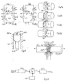
- Fig. 12 illustrates a modification of the embodiments of the transducers and transducer assemblies described above in which provision is made to prevent the creation of a bar magnet in the shaft or elongate member in which the transducer region is incorporated. This applies particularly to D.C. energised transducers but may also be applied to reduce the likelihood of residual magnetisation occurring in A.C. energised transducers.
- Fig. 12 shows a shaft or elongate member 120 on which an excitation coil L D is mounted about transducer region 122. The sensor arrangement is not shown. To each side of coil L D a respective coil L CL and L CR is mounted. The coils L CL and L CR are energised at the same time as coil L D , as by being connected in series therewith as shown in Fig. 12, and generate fields of opposite polarity to that generated by coil L D . The coils L CL and L CR are sufficiently spaced from coil L D to allow the desired transducer region field to be generated and sensed in the manner already described.
- each of the three coils produces an individual field as shown in Fig. 2.
- coil L CL as an example the field toward coil L D is of the same polarity as that of coil L D towards coils L CL, i.e. the fields tend to repel one another.
- An equivalent situation arises between coils L D and L CR.
- the coils L CC and L CR should not be so close to coil L D as to adversely affect the torque- or force-dependent field which it is sought to measure.
- the effectiveness of the coils L CL and L CR in reducing the formation of a bar magnet in shaft or elongate member 120 may be judged by a sensor located to detect the axial field extending outwardly of a coil L CL or L CR . This field should be reduced to substantially zero.
- the shaft or elongate member in which the transducer region is created may be subject to a de-gaussing procedure prior to being put into use. Such a procedure is described in published PCT application WO01/79801.
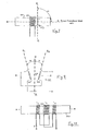
- Figs. 13a and 13b show the physical arrangement of a torque transducer embodying the present invention. It is applied to a shaft 210 which is rotatably mounted about a longitudinal axis A-A about which a torque T is applicable.
- the torque may be clockwise (CW) or counter-clockwise (CCW).
- the shaft does not necessarily have to rotate continuously or at all.
- the shaft 210 is assumed to be of circular section with the axis A-A being central.
- the shaft or at least the region of it of interest to transducer operation is of ferromagnetic material.
- Two coils 212 and 214 are mounted to be wound about the shaft and are energisable to induce an axially-directed (longitudinal) magnetic field in the shaft.
- the coils are spaced apart and define therebetween a transducer region 216 of the shaft.
- the coils are connected in series to receive an energisation current I, the coils being connected in series in additive fashion to co-operate to generate a longitudinal magnetic field in region 216 generally indicated by arrow M.
- the generated field is discussed below.
- the direction of field M depends on the polarity of current 1.
- the longitudinal field M is axially-directed but is deflected by torque T acting about axis A-A in transducer region. Although the field is primarily confined within the material of the shaft, an external field component will arise which affords the possibility of detection of the field by a non-contacting sensor arrangement.
- the deflection under torque creates a tangential or circumferentially-directed field component whose magnitude and direction is a function of the direction and magnitude of the torque.
- This component can be detected by a magnetic field sensor device 218 which as shown in Figs. 13a and 13b is tangentially oriented to be sensitive to the circumferentially-directed or tangential component.
- Magnetic field sensing devices that may be employed include Hall Effect, magnetoresistive and inductor (saturating core) types. They are available as small units.
- One particular device which has been satisfactorily used is the saturating core type of device connected in a signal conditioning circuit of the kind disclosed in WO98/52063.
- a single sensor device may be used in the practice of this invention where prior magnetic transducers would have required two or more sensor devices for cancellation of an interfering magnetic field, such as the Earth's field. This assists in placing the transducer assembly in a location where space is at a premium. An example is given in Fig. 19 below.
- FIGs. 14a and 14b illustrate a modification to position the sensor device within the confines of the outline or profile of the shaft 210.
- the device 218 is external to the cylindrical profile of the shaft 210
- the transducer region 216 (the coils are not shown) has a notch or recess 217 within which the sensor device 218 is received so as to be recessed within the circular outline of the shaft.
- the device could be received within a bore in the shaft.
- the modification of the housing of the sensor device 218 within the shaft profile, or substantially so, also brings an attendant advantage that the device is going to be in a stronger magnetic field.
- Fig. 14a needs additional measures where the shaft 210 is to rotate continuously or is rotatable over a given arc - for example the shaft may move back and forth - with respect to a fixed sensor device 218; or where the sensor device 218 is to rotate with the shaft 210 over whatever angle is appropriate.
- the notch or recess 217 can be extended as far as necessary to form a groove entirely or partly around the shaft as indicated at 217a in Fig. 14a.
- This measure may be applied to the torque drive or adapter unit of Fig. 19 where the sensor device is fixedly mounted to the wall of housing 250. It is easier to connect the sensor device into signal processing circuitry in this case. Nonetheless it is possible to have the sensor device mounted to the shaft to rotate therewith.
- the sensor device 218 secured in the recess as shown could be connected to slip rings extending around the shaft and engaged by fixed contacts. The connections could be made to run along an axial bore in the shaft to a suitable signal pick-off point.
- the sensor device could be incorporated in a complete self-contained unit mounted in notch or recess 218 designed to radiate a torque-dependent signal to a separate receiver as by induction coupling (magnetic coupling) or by electromagnetic radiation or any means by which a remote communication link is established.
- the energising current waveform be bipolar pulses of low duty cycle, e.g. short duration, spiky pulses.
- the adoption of such a waveform leads to important operational advantages as compared, for example, to the use of a bipolar pulse waveform of essentially 100% duty cycle such as a bipolar square wave.
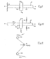
- An energising current waveform suitable for the practice of the present invention is shown in Fig. 15a. the magnetic field pulse waveform will follow the current waveform.
- Such a current waveform can be generated by differentiating a bipolar square wave.
- the precise waveform nor the means of generating it is not restricted to a differentiated bipolar square wave. It does serve, however, to indicate the nature of a short duration, spiky pulse wave of alternating polarity (AP) magnetic field pulses generated in the transducer region 216.
- the current pulse generating source 220 has its frequency controlled by a frequency source 221 though, of course, the two sources could be realised by a single unit.
- Source 221 is preferably a frequency-stable square wave source at a frequency unrelated to the local power (mains) frequency.
- Fig. 16 shows a simplified circuit for the drive source 220 to which the coils 212 and 214 are connected.
- the coils are connected in series with a capacitor C across one diagonal 222 of a switching full-wave bridge circuit 224 to the other diagonal 226 of which a D.C. power supply is connected.
- Controllable switches S1-S4 in respective arms of the bridge are controlled to generate a bipolar waveform across diagonal 222 which is subject to the differentiation characteristic provided by capacitor C to generate short current pulses of low duty cycle in the series coils 212, 214.
- the switches S1-S4 are implemented in practice by any appropriate kind of controllable switch device, such as a semiconductor device.
- the switch devices have respective control inputs for receiving switching control signals B and NOT-B at a desired frequency derived from the source 221 of Fig. 13, the switch pair S1 and S4 being turned on and off alternately and inversely with switch pair S2 and S3.
- Fig. 16 shows the bridge 234 in one half-cycle of operation (switches S2 and S3 on with switches S1 and S4 off). As switches S2 and S3 close, current I is driven through the bridge and the coils 212 and 214 as shown by the arrows. The capacitor C enables a high initial current pulse to pass through the coils. The capacitor charges positively at junction with S2. The circuit parameters are chosen so that the pulse is short relative to the switching period of control signals B, NOT-B.
- Fig. 16a indicates the generation of the current pulse of opposite polarity in the next half cycle with S1 and S4 closed and S2 and S3 open. It will be seen from this figure that the generation of the pulse involves not only the charging of the capacitor to the opposite polarity but it is preceded by the discharging of the charge acquired on the previous half cycle.
- the form of the magnetic pulses in the shaft will follow the current I in the coils rather than the voltage waveform applied across diagonal 222.
- the exact form of the current waveform is dependent on the inductance of the coils, which resists any sudden change in current, and substantially on the ratio of the inductance to resistance.
- the use of a series capacitor in the current flow, and specifically placed in the diagonal in which the coils are connected, leads to two advantages, the current waveform is predominantly controlled by the capacitor C as illustrated in Figs. 15a and 15b and it provides an effective time constant relative to the pulse period (here, the interval between a pair of alternating polarity pulses) that is short so that the current has reduced to near zero for the first pulse before the next pulse is generated.
- V T1 and V T2 are of equal magnitude, minimising the possibility of building up a unipolar remanent magnetisation in the shaft due to the switched waveform itself.
- the pulse current levels should be chosen to provide adequate signal output and signal/noise but without tending to produce undue levels of remanent magnetisation in the shaft material. This is consistent with obtaining the desired pulse waveform of Fig. 15b.
- the actual current level, or more specifically, the ampere-turns of field exerted on the shaft will be dependent on the size (diameter) of the shaft and the material of which it is made with particular regard to magnetic characteristics. For shafts in the range of 15-20 mm of industrial-type steels, e.g. FV250B, it is presently considered that the working emanated longitudinal field closely adjacent the shaft should not exceed about 30 Gauss.
- the full-wave bridge 234 enables bipolar pulses to be generated from a unipolar power supply which may be of a single polarity with respect to a ground reference or a dual polarity supply.
- Figs. 17a-17c shows the transducer region 216 with a tangentially-oriented saturating core inductor sensor device 218'.
- the longitudinal magnetic field M generated by the coils 212 and 214 (not shown) is indicated by multiple parallel arrows.
- the field is axially-directed: there is no tangential field component to be sensed by device 218'.
- Figs. 17c and 17d correspond to Figs. 17a and 17b but in the presence of an applied torque.
- the field M is deflected or skewed in a direction dependent on the sense of the applied torque T and to an extent dependent on the magnitude of the torque.
- a resultant tangential field component is detected by sensor device 218' and a pulsed output signal V T is generated by the sensor circuitry as indicated in Fig. 15b. in synchronism the coil pulses.
- the output pulses are of alternating polarity and have a magnitude which is dependent on the applied torque. For an applied torque of opposite sense the sense of the output pulses would likewise be reversed.
- the amplitude of the individual output pulses is a measure of torque but is subject to error from interfering fields which may be unknown and unpredictable. Considering first D.C. or unipolar fields, they may result in an unknown level of the quiescent field V Q detected by sensor 218' on which the torque-dependent signal V T is superposed. Thus a measurement of the peak value of a single output pulse of the signal V T is error prone.
- An improved measurement of torque acting to cancel any D.C. interference component is obtained by making a Vpp peak-to-peak measurement Vpp between successive output pulses of opposite polarity, e.g. V T1 - V T2 .
- this peak-to-peak measurement technique enables a single sensor device in a single location to be used without interference from fields such as the Earth's magnetic field.
- cancellation of the Earth's field has required at least two sensor devices.
- a second step directed towards excluding local noise spikes that may occur is to gate the peak measurements in synchronism with the applied current waveform so that the peak measurement gate t g is only opened for a period in which each torque-signal output pulse is expected.
- Another way of approaching the same problem is to have a phase-sensitive detection arrangement synchronised to the drive current waveform.
- Fig. 18 shows a block diagram of a processing circuit for the sensor output signals V T .
- the sensor device 218(218') is connected to a signal conditioner circuit 230 which produces the torque-dependent output signals V T (Fig. 15b).
- This output is fed to a gate circuit 232 controlled by frequency source 221 (including control derived from the coil drive current waveform).
- the gate opens at the times t g related to the drive pulses at which a torque-dependent output pulse is expected.
- the pulses passed by gate 232 are applied to a peak-to-peak detector 234 whose torque-dependent peak-to-peak output V PP is used as the wanted torque-output signal, subject to any smoothing or other processing required.
- the gating technique assists in discrimination against random magnetic noise spikes. It will also be understood that by selection of the frequency of operation of the source 220, e.g. bridge 224, additional discrimination can be obtained against noise related to the local power (mains) frequency.
- the adaptor 240 has an upper circular cylindrical body 242 having a shaped input recess 244 for receiving a matching keyed output shaft of a power tool. Descending from body 242 is a reduced diameter body 246 in the form of a short shaft terminating at its lower end in a key 248 to engage a matching nut or bolt head.
- the adaptor is received in a housing 250 which allows little room to receive magnetic field sensor devices.
- the adaptor will normally receive a series of impulses of increasing torque from the power tool and, particularly in the case of impact-action power tools, the nature of the successive impacts may be deleterious to a magnetic-based, torque transducer assembly fitted around a region of the shaft 246 relying on stored magnetism and used as a transducer element.
- a magnetic-based, torque transducer assembly fitted around a region of the shaft 246 relying on stored magnetism and used as a transducer element.
- the adaptor Apart from the violent shocks to which the adaptor is subject, there is always the possibility of interfering magnetic fields being set up through the adaptor between the power tool and the product on which it acts as well as a generally noisy environment particularly related to mains power.
- the present invention may be used advantageously in such a hostile environment by applying the teachings described above to the shaft body 246 to measure the torque therein. Furthermore a transducer assembly embodying the invention can be assembled in the restricted space available. The coils would about the shaft 246 require little space external to the shaft. The sensor arrangement requires only one sensor device and that may be located within the profile of shaft 246 by adopting the arrangement of Fig. 13b.
- transducer assembly of the invention has been described thus far with reference to a transducer element defined between a pair of coils, as shown in Figures 13 to 19.
- a tangential or circumferentially-directed, torque-dependent magnetic field component can be obtained with a single coil.
- Fig. 20 shows the principle of such an assembly.
- a transducer region 216' of a shaft 210 is defined by the position of a single coil 212'.
- Energisation (I) of the coil creates an axially-directed field in the region 216' with an accompanying external longitudinal field 217 which extends in an annulus about the shaft.
- a tangential or circumferentially-directed component arises which is detectable by a tangentially oriented sensor 218".
- the sensor is mounted very close in to the coil in this case to be within the field generated by the coil. It may be housed within the profile of the shaft as in Figs. 14a and 14b.
- the transducer assembly of Fig. 20 may also be applied to the measurement of a tilt or skew of the axis A-A of the shaft relative to the axis of the coil due to an applied force acting to tilt or skew the axis of the shaft, or other elongate member, as indicated in dotted line by arrows FF.
- Fig. 20 also shows the possibility of using a second, axially-oriented, sensor device or devices 219 for detecting the external axially-directed component of the longitudinal magnetisation.
- a sensor device(s) can be used to provide a reference signal representing the field strength generated by the coil or coils.
- the wanted peak-to-peak signal can be measured or calibrated against the reference level.
- the reference level can be used to control the gain factor of the transfer function of the transducer.
Abstract
Description
- This invention relates to a method and apparatus for the measurement of torque in a part such as a shaft. The invention also relates to a method and apparatus for measuring a force which gives rise to a tilt or skew of an elongate member. The invention still further relates to a transducer assembly, in particular a magnetic-based transducer and transducer assembly.
- Magnetic transducer technology has gained wide acceptance for measuring torque in shafts or other parts for transmitting torque. Magnetic-based torque transducers have found application in non-contacting torque sensors particularly for a shaft which rotates about its longitudinal axis. One or more magnetic regions, used as one or more transducer elements, are created in or on the shaft to emanate a torque-dependent magnetic field component external to the shaft which is detected by a sensor arrangement that is not in contact with the shaft.
- The following description will be given in the context of shafts but will be understood to apply to measuring torque in parts in general, unless the context otherwise requires.
- One class of magnetic region used as a transducer element in torque transducers is self-excited in that it is a region of permanent or stored magnetisation which emanates an external torque-dependent field. The transducer region is sometimes referred to as "encoded" in that a predetermined configuration of magnetisation is stored in it.
- A transducer element may be created in a region of stored or permanent (remanent) magnetisation in a ferromagnetic integral region of the shaft or part. Transducer elements of this kind are disclosed in published PCT applications WO99/56099, WO01/13081 and WO01/79801. The stored magnetisation may be of the kind known as circumferential in an integral region of a ferromagnetic shaft as disclosed in WO99/56099 or it may be a circumferentially-magnetised ring secured to the shaft as disclosed in U.S. patent 5 351 555. Circumferential magnetisation forms a closed peripheral loop about the shaft and produces an axially-directed external field in response to applied torque. Another form of stored magnetisation is an integral portion of a shaft in which the stored magnetisation is in an annulus about the axis of the shaft and is directed longitudinally, that is in the direction of the shaft axis. One kind of longitudinal magnetisation is known as circumferential (tangential)-sensing longitudinal magnetisation and is disclosed in WO01/13081; another kind is known as profile-shift longitudinal magnetisation as disclosed in WO01/79801 .
- All these forms of transducer magnetisation are "D.C." magnetisations in the sense they operate with unipolar magnetic fluxes generated by the remanent magnetism stored in permanent magnets.
- The sensor devices used with self-excited transducer elements may be of the Hall effect, magnetoresistive or saturating core type. These sensor-devices are sensitive to orientation. They have an axis of maximum response, and an orthogonal axis of minimum response.
- Another class of magnetic transducer region is externally excited by an energised coil wound about the region. One form of externally-excited transducer is the transformer type in which the region couples an excitation winding to a detector winding, the coupling being torque-dependent. For example the permeability of the transducer element may be torque dependent. The transformer-type of transducer is A.C. energised. An example of a transformer-type of transducer is disclosed in EP-A-0321662 in which the transducer regions are specially prepared to have a desired magnetic anisotrophy at the surface.
- Under conditions of severe mechanical stress where the torque transmission is subject to blows, impacts or other sharp pulses, the stored magnetisation may deteriorate and the transducer operation become unsatisfactory. In addition the torque measurement may need to be done in circumstances where there are interference magnetic fields of a largely unknown and unpredictable type. Such fields are likely to arise in production plants and such like environments. Magnetic field interference can arise from unipolar fields, noise spikes and "A.C." fields at the local powerline frequency, among others.
- Another form of externally-excited transducer element is disclosed in WO01/27584 in which the magnetisation of a region of a shaft arises from energisation of one or more coils are mounted coaxially with a shaft in which an applied torque is to be measured. The coils are axially spaced and define a transducer region therebetween. The coils are connected in series to generate magnetic fields in the same direction in the transducer region between the coils. The coils are energised to induce a longitudinal magnetic field of a given polarity. The longitudinal field in the transducer region is deflected in direction and to an extent dependent on torque applied to the shaft to produce an external circumferential (tangential) magnetic field component that is a function of torque. The axially-directed component of the field is separately detected to provide a reference against which the circumferential component is measured. If the coils are D.C. energised the resultant magnetic field may be interfered with by other local fields, e.g. fields extending along the shaft whose torque is to be measured.
- In the torque measurement system disclosed in WO01/2758 the pair of spaced coils is A.C. energised at a frequency selected to be distinguishable from noise frequencies, e.g. mains power frequency, and the sensor output is also detected in a frequency-selective manner. The torque-dependent "A.C." or alternating polarity (AP) magnetic field component is detected. By using A.C. energisation interfering D.C. fields can be discriminated against and the A.C. frequency can be selected to discriminate against interference as the local power line or supply frequency, e.g. 50 or 60 Hz. The detection may be synchronous with the A.C. energisation. The external field to be sensed is enhanced by a pair of spaced collars of magnetic material attached to the transducer region to aid the establishing in a recess between the collars of an external component of the longitudinal field in the transducer region. A sensor arrangement responsive to a torque-dependent magnetic field in the circumferential (tangential) arrangement is disposed in the recess.
- The just-described transducer has the advantage that the transducer region does not have to be encoded with a stored magnetisation. Nonetheless a transducer region has to be defined between a pair of spaced coils. It would be advantageous to provide a transducer assembly in which no encoding is required and which could be realised in compact form and installed at any convenient location on a shaft or other part subject to torque.
- The prior art also discloses various magnetic field sensor arrangements using two or more sensor devices to compensate for potential measurement errors and to assist in nullifying the effects of interfering fields. Although small, such sensor arrangements may be difficult to accommodate in situations where space is at a premium.
- The present invention seeks to provide a technique which affords a magnetic-based transducer greater immunity from interfering fields. It also can be implemented in a compact form using a single sensor device for detecting a torque-dependent magnetic field component. To this end a transducer element has a torque-dependent field created therein by energisation of a single coil. The transducer region is subjected to short duration magnetic pulses of alternating polarity and a differential measurement is made on these pulses as detected by a sensor arrangement. Specifically the differential measurement is a peak-to-peak measurement. Such a measurement can be satisfactorily realised with the aid of a single sensor device acting at a single location.
- As will be explained hereinafter, the present invention can be implemented in hostile environments such as those subject to shocks and where interference fields of an unpredictable nature may occur.
- Aspects and features of this invention are set forth in the claims following this description. Embodiments mentioned in the description and the drawings with more than one single coil as defined in the claims are not encompassed in the invention.
- One aspect of the present invention has arisen out of the consideration t hat if a coil is placed a bout a ferromagnetic shaft subject to torque and the coil energised with current, a magnetic field will be induced, at least in an annular zone of the shaft adjacent the surface. This field will be generally axially-directed. Such a field in the region of the shaft where the coil is located is distorted by a torque to generate a magnetic field component in the circumferential (tangential) direction w hose magnitude a nd direction are dependent on the magnitude and direction of the torque. Although the magnetic field is primarily generated in the shaft region within the coil, sufficient external field exhibiting the desired torque-dependent characteristic is found closely adjacent each end of the coil and can be detected by a sensor located close in to the coil. The external diameter of the shaft should be a close match to the internal diameter of the coil, which may be supported on a former, enabling the field generated by the coil to penetrate the shaft while allowing the shaft to rotate within the coil. In addition a second sensor can be located to detect a field component generated by the coil such as a longitudinal or axially-directed component, which is unaffected or substantially so, by torque. The signal from the second sensor can be used to develop a reference signal against which the torque-dependent field component is measured.
- Another aspect of the present invention has arisen out of the consideration that if a coil is placed about a ferromagnetic elongate member subject to a force transverse to the axis of the member and the coil is energised with current, a magnetic field will be induced, at least in an annular zone of the shaft adjacent the surface. This field will be generally axially-directed. Such a field in the region of the member where the coil is located is distorted by a transverse force applied to the elongate member, the force acting to tilt or skew the axis of the elongate member relative that of the coil. The force results in the generation of a magnetic field component in the circumferential (tangential) direction whose magnitude and direction are dependent on the magnitude and direction of the tilt or skew and thus of the force which gave rise to it. Although the magnetic field is primarily generated in the region of the elongate member within the coil, sufficient external field exhibiting the desired-force dependent characteristic is found closely adjacent each end of the coil and can be detected by a sensor located close in to the coil. The external cross-section of the elongate member should be a sufficiently close match to the internal cross-section of the coil, which may be supported on a former, to enable the field generated by the coil to penetrate the shaft while allowing the elongate member to tilt or skew (flex) within the coil. The elongate member may be subject to a bending moment due to an applied force. Alternatively it could be pivotally mounted to allow angular displacement about the pivot in response to an applied force. In addition a second sensor can be located to detect a field component generated by the coil, such as a longitudinal or axially-directed component, which is unaffected, or substantially so, by the force being measured. The signal from the second sensor can be used to develop a reference signal against which the force-dependent field component is measured.
- The invention and its practice will be further described with reference to the accompanying drawings.
-
- Fig. 1 schematically shows a shaft to which is mounted a transducer assembly;
- Fig. 2 illustrates the detectable external magnetic field generated by the energised coil of the assembly of Fig. 1;
- Fig. 3a shows a perspective view of a transducer comprising a unitary transducer assembly mounted on a shaft with a sensor device at each side of the coil;
- Fig. 3b is a schematic illustration of the transducer of Fig. 3a with the addition of a reference sensor device;
- Fig. 4 illustrates a sensor arrangement with two inductive-type sensor devices (saturating core sensors) arranged to provide cancellation of an extraneous field;
- Fig. 5 shows a sensor arrangement of four sensors providing cancellation of extraneous fields;
- Fig. 6 schematically shows an A.C. energised transducer system;
- Fig. 7 illustrates factors to be considered relating to movement of the shaft relative to the transducer assembly;
- Fig. 8 illustrates one sensor arrangement for reducing the sensitivity to axial skew or tilt of the transducer assembly relative to the axis of the transducer region;
- Fig. 9 illustrates one embodiment using a transducer in the measurement of a force by utilising the sensitivity to tilt or skew;
- Fig. 10 illustrates a second embodiment for the measurement of a force;
- Fig. 11 shows an implementation of the force-measuring embodiment of Fig. 9 or 10 in measuring tension in a running thread or other similar lengthwise-moving flexible item;
- Fig. 12 shows a modification of the transducer assembly including further coils to reduce the possibility of establishing remanent magnetisation in the transducer region;
- Fig. 13a shows a perspective view of a transducer assembly of a transducer element and sensor device embodying the invention applied to a shaft;
- Fig. 13b shows an end view of the shaft and transducer assembly of Fig. 13a;
- Figs. 14a and 14b show perspective and end views of a modification to the shaft to house the sensor device within the profile of the shaft;
- Fig. 15a illustrates a bipolar pulse drive current waveform for the coils of the transducer assembly;
- Fig. 15b illustrates an output waveform representing the torque-dependent magnetic field component as detected by the sensor device;
- Fig. 16 shows a drive circuit in which the transducer energising coils are connected, the circuit being in one half-cycle of operation;
- Fig. 16a shows the drive circuit the next half-cycle of operation;
- Figs. 17a-17c shows the magnetic field in the transducer region of the shaft in successive half-cycles of operation for no-torque and torque conditions respectively;
- Fig. 18 is a block diagram of a signal processing circuit for the sensor device signals;
- Fig. 19 illustrates an application of the invention in a torque wrench adaptor, and
- FIG. 20 shows a modification of the transducer assembly of the invention using a single energising coil.
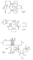
- Fig. 1 shows a
shaft 10, which is assumed to be of circular cross-section and which is mounted for rotation about its longitudinal axis A-A. The shaft may continuously rotate, rotate over a limited angular range, or even be held at one end while torque is applied at the other. Torque T is shown as applied atend 12 to drive a load (not shown) coupled to end 14. - A coil LD is mounted about a
region 20 of the shaft which is to act as a transducer region for measuring torque in the shaft. At least the transducer region of the shaft is of ferromagnetic material. The transducer region should have an axial length sufficient for the establishment of the desired field within the material of the shaft and allowing for axial displacement of the shaft with respect to the coil as may occur in some practical applications. Theregion 20 is indicated by the dash lines which are notional limits. The coil LD is a helical coil, single or multi-layer, coaxial with shaft axis A or it may be pile wound on a former. The coil is energised by asource 22 about which more is said below. At least onesensor device 23 is mounted closely adjacent the coil LD andregion 20, that is thedevice 23 is closely adjacent the axial hollow in the coil in which the shaft is received. Thedevice 23 is oriented to have its axis of maximum sensitivity in a tangential or circumferential direction. A t least onesensor device 24 is mounted adjacent the coil to have its axis of maximum sensitivity in the axial or longitudinal direction. The functions ofsensors sensors source 22 which energises the coil LD may be D.C. or A.C. as discussed more fully below. Preferably the source is adjustable to control the level of energisation of coil LD. - WO01/27584 discloses in Fig.8a thereof, how a longitudinal field is generated between two spaced coils wound about a shaft. The transducer region is in the zone between the two coils. In contrast, in the embodiment of Fig. 1 the transducer region lies within and extends somewhat beyond the excitation coil LD. Fig. 2 shows the general form of the
external field 30 generated by a current I applied in coil LD. It extends in an annulus about axis A-A. It will extend in an annulus of axially-directed magnetisation (longitudinal magnetisation) within thetransducer region 20. The annulus extends inwardly from the shaft surface. The internal field is not shown in Fig. 2. For best results the coil LD should couple as closely as possible to theferromagnetic transducer region 20. The coil may be wound on a former that closely fits over theshaft 1 0, while allowing rotation of the shaft within the former. It has been found that thefield 30 close in to the coil LD and closely adjacent theregion 20 is torque-sensitive and provides a tangentially-directed component under torque whose polarity and magnitude are dependent on the direction and magnitude of the torque applied about axis A-A. Thesensor 23 is positioned to be responsive to this tangentially-directed component. Thesensor 24 is positioned to provide a signal representing the overall level of field generated by coil LD preferably an axial component that is substantially unaffected by torque. - Fig. 3a shows a perspective view of a
shaft 10 on which is mounted a close-fitting former 32 on which the coil LD is wound. The former 32 hasend cheeks 34a and 34b closely adjacent to which and the shaft surface are mountedsensor devices 23a and 23b with their axes of maximum sensitivity tangential to the shaft. The arrangement is shown schematically in Fig. 3b in which thedevices 23a and 23b are represented as inductances wound on saturating cores. As already indicated, thecoil 24 can be mounted in the vicinity of the coil LD at any point where there is an axially-directed field component from which a reference signal can be generated against which the torque-dependent signals fromsensors 23a, 23b can be measured or, put another way, which is used to control the gain of the transducer. - Fig. 4 shows how each
sensor device 23a, 23b can be provided as a sensor arrangement comprising a pair of radially-opposite sensor devices. Fig. 4 shows a cross-section throughtransducer region 20 and shows thesensor device 23a as now being a sensor arrangement comprising a pair of devices 23a1 and 23a2 mounted on opposite sides of thetransducer region 20 ofshaft 10, i.e. diametrically opposed with respect to axis A-A. The remainder of the transducer assembly is not illustrated. In the cross-sectional view of Fig. 4 the torque-dependent field components are denoted Ms and are oppositely directed o n diametrically opposite sides ofregion 20 so that the respective device coils 23a1 and 23a2 are connected in series additively as regards the torque-dependent components Ms but are connected subtractively to cancel an external field E acting on both sensor devices in common. The sensor devices 23a1 and 23a2 are connected in series to a signal-conditioner circuit 36 from which is obtained a torque-representing output signal, VT. - The
shaft 10 may be subject to a bending moment causing a deflection of it at thetransducer region 20 from the axis A-A. The shaft may also be subject to some wobble of its axis in its rotation. If the shaft deflects perpendicularly to the direction of arrows, that is toward one of the sensor devices and away from the other, the one device will provide a larger signal output than does the other. Because the outputs are additively connected, such a deflection will be compensated, at least to some extent. The compensation is not exact because the field strength sensed by the devices is a square law function of distance from the shaft surface. But normally such deflections are expected to be small and a high degree of compensation is afforded. - If the deflection is in the direction of (or opposite to) the arrow s, provided that it is small and within the lateral sensing extent of the sensor devices i.e. not resolvable by the devices, the combined signal output will not be affected. As the deflection increases, each sensor device 23a1, 23a2 yields a lesser torque signal output. However, there is also a signal generated in each device due to the deflection itself even if the shaft is not rotating. The deflection is a common mode effect and is cancelled by the connection of the two devices. This subject is further discussed below with particular reference to Fig. 7.
- The sensor arrangement disposed adjacent one end of the coil LD can be extended further. For example Fig. 5 shows an additional pair of sensor devices 23a3 and 23a4 mounted diametrically radially opposite one another with respect to
transducer region 20 and orthogonally with respect to devices 23a1 and 23a2. Devices 23a1 and 23a2 are additively connected with one another, and with devices 23a1 and 23a2 as regards the torque-dependent field components but are subtractively connected with respect to a magnetic field component E'. - It will be appreciated that the same use of one or more pairs of sensor devices can be adopted for sensor device 23b of Figs. 3a and 3b. It will also be noted that it is not necessary for the
sensor devices 23a and 23b, or the more complex sensor arrangements thereof, to be aligned in angular disposition about the shaft. It will be also appreciated that each sensor device can be connected into a respective detection circuit and the outputs of the individual circuits combined as required. - The description of the practice thus far has assumed a D.C. energisation of the coil. This leads to what may be called a D.C. magnetic field. For reliability of response in using a D.C. field, it is desirable that the
shaft 10 be subject to a de-gaussing or magnetic cleansing procedure as is described in above-mentioned WO01/79801. In the sensor arrangements discussed above, the adoption of a D.C. magnetic field leads to the fastest torque-signal response with the circuitry currently in use. That is the overall circuitry exhibits the highest bandwidth for signal changes. However, A.C. magnetisation may also be employed. A.C. energisation has some advantages but also entails consideration of other factors. AnA.C. transducer system 40 is illustrated in Fig. 6 and may be compared to that shown in Fig. 12 of WO01/27584. AnA.C. source 42 energises coil LD at a frequency f. The source may be a bipolar pulse source. Asignal conditioner circuit 44 connected tosensor arrangement 24 is provided with afilter function 46 to extract the magnetic field component at frequency f detected bysensor arrangement 24. The filter may be driven from thesource 42 to ensure thefilter 46 tracks the source frequency f as is indicated by the chain line. Synchronous detection in which a detector incircuit 44 is driven by a signal fromsource 42 may be employed. Similarly thesensor arrangement 23 is connected into a frequency-selectivesignal conditioner circuit 48 includingfilter function 50 to provide an output representing the torque-dependent field component. This component together with a reference level component obtained fromcircuit 44 is applied to asignal processing circuit 52 from which a torque-representing output VT is obtained. It will be understood that the filtering and signal-processing functions may be performed in hardware or software and that the filtering may be performed at various points in the complete signal path. It is desirable that the operating frequency f of the source/filter system be selected to be well-distinguishable from frequencies of potential interfering sources, e.g. power (mains) frequency. - Saturating-core types of sensor are capable of operating up to 10 kHz or more but in addition to the sensor response consideration has to be given to the source frequency response in its ability to drive the coil LD. There is another frequency-dependent characteristic to be considered, particularly when the transducer region is an integral portion of a shaft.
- The depth of penetration of the coil field into the material of the transducer region is frequency-dependent. It is greatest a zero frequency, i.e. D.C., and decreases as the drive frequency increases. For example, a shaft of FV25OB steel of a diameter of 18 mm, was penetrated entirely by a D.C. energised coil but was not entirely penetrated by the equivalent A.C. current at 100 Hz. Penetration of the entire cross-section of the transducer region is not essential as the torque-dependent response tends to be concentrated in a surface-adjacent annular zone. However, as the frequency increases it is found that the gain or slope of the transfer function - the torque-dependent signal output v. applied torque - will have a tendency to decrease.
- The transducer and transducer assembly described above provides the following benefits:
- the assembly of coil (with former) and sensor arrangement or arrangements can be manufactured as a unitary component mountable to a shaft; the unitary structure may also comprise signal conditioning and processing circuitry;
- the manufacturing process does not require a ny encoding procedure for the transducer region to establish a permanent magnetisation therein; in a homogeneous shaft, there is freedom as to where the transducer region is to be established and there is no critical aligning of the transducer assembly with a predetermined region of the shaft.
- there is no degradation of the magnetisation of the transducer region over time as can occur with a permanent magnetisation;
- the gain or slope of the transfer function of the transducer is a function of the drive current to the transducer coil. It has been found that short of energisation current levels creating a non-linear response, response sensitivities are obtainable substantially greater than achievable by the aforementioned profile-shift magnetisation;
- the transducer is insensitive to axial displacement of the transducer region with respect to the transducer coil/sensor assembly;
- the ability to operate in an A.C. fashion at a selected frequency allows operation within a noisy environment and renders the transducer more tolerant of stray magnetisms in the shaft.
- Another factor to be considered for both D.C. and A.C. implementations is illustrated in Fig. 7 which shows the
shaft 10, energising coil L and asensor device 23 oriented to detect a tangential torque-dependent component. The axis B-B maximum sensitivity of asensor device 23 is oriented at an angle of α to the axis A-A of the shaft. Axis A-A lies in the plane of the figure, axis B-B is parallel to and above the plane of the figure. Angle α is thus the angle between axis B-B as projected onto the plane of the figure and is ideally 90°. As compared to some forms of permanently-magnetised transducer regions, the transducer assembly described above is not sensitive to axial shifts of the transducer region, assuming the transducer region is bounded by shaft material homogeneous therewith as would be the case with a shaft homogeneous along its length with which the transducer region is integral. However, the operation of the transducer assembly (coil plus sensor arrangement) is sensitive to axial skewing or tilting of the shaft relative to the assembly that affects the angle α. - Attention will now be given to the sensitivity to axial skewing and measures to mitigate it. It will also be shown that conversely a transducer-assembly described above can be implemented to use axial skewing in an advantageous manner to enable a measurement of a force to be made.
- Referring again to Fig. 7, consider the situation where there is no torque in the
shaft 10 but the shaft axis tilts relative to the axis of coil LD so that the angle α is no longer 90°. The coil is energised. - The result is a transverse component of the magnetic field generated by the coil LD which is detected by
sensor device 23. If a sensor arrangement such as shown in Fig. 4 is employed the skewing, indicated by arrow S, will be in the same direction relative to both sensors 23a1 and 23a2. As regards the detected field, the skew acts as a common mode component and is cancelled in the output similarly to the common external field E. This common mode rejection is equally obtained when the shaft is under torque. When under torque as kew orthogonal to arrow S will tend to increase the component MS at, say, sensor device 23a1 and decrease component MS at sensor 23a2 with little effect on the combined output signal VT. This is true generally of wobble of theshaft 10 in its rotation. This foregoing reasoning can be extended to the sensor arrangement of fig. 5 with reference to a skew orthogonal to direction S. - Another approach can be adopted to making an individual sensor such as 23 in Fig. 7 less sensitive to skew. This is illustrated in Fig. 8 in which the
single sensor device 23 is shown as being replaced by asensor unit 60 comprising a pair of devices 62 and 64. The shaft as such is not shown but its axis A-A is indicated. B-B is the axis of response ofsensor 60, desirably at an angle α = 90° to axis A-A. the two sensor devices are offset at an angle θ to each side of axis B-B, that is their respective axes B1, B2 maximum sensitivity are separated in a "V" formation by angle 2θ. - In measuring a torque-dependent field component, which affects both sensor devices substantially equally, if there is a tilt - α moves from 90° - the field sensed by one device increases while the field sensed by the other decreases. If the two devices are connected additively, dot to non-dot end, the resultant signal is far less affected by angular skew or tilting than that of a single device, particularly for small deviations of α from 90°. This would normally be the case. The angle of deviation should not exceed the angle θ.
- The immediately preceding discussion has been concerned with measuring torque in the presence of an angular tilt or skew of the shaft relative to the transducer coil assembly and its associated sensors. One circumstance in which such a skew or tilt may arise is if the shaft, the torque in which is to be measured, is subject to a transverse force leading to a bending moment in the shaft at the location of the transducer region. The sensitivity to any resultant axial tilt or skew, in the absence of compensatory measures, can be utilised to measure the applied force. Furthermore, this force measurement is not restricted in its application to a shaft in which a torque is transmitted. The force measurement can be applied to any elongate member subject to a bending moment due to an applied force or even an elongate member pivotally mounted to turn about the pivot axis in response to an applied force. The elongate member is to be capable of supporting or having incorporated into it a transducer region with a transducer assembly as has been described above but with a modified sensor arrangement.
- Fig. 9 shows an
elongate member 70 which is fixed at oneend 72 and theother end portion 74 of which is free to move under a force F applied transversely of a longitudinal axis A-A ofmember 70. Themember 70 is resilient and relatively stiff so that it yields to the bending moment impressed by the force F to deflect at anintermediate region 76 to an extent which is function of the applied force. Theintermediate region 76, at least, is of ferromagnetic material and provides a transducer region for atransducer assembly 78 comprising an excitation coil aboutregion 76 and a sensor arrangement configured to respond to the deflection of themember 70 with respect to the axis of the coil of transducer assembly which remains aligned with the axis A-A of theunstressed member 70 with no force F applied to it. The transducer assembly is constructed as previously described and with particular reference to the detection of tilt or skew. The effect of the deflection of the elongate member is that of the angular tilt or skew already described, where theshaft 10 is no longer a torque transmitting part but i s now replaced by the deflectableelongate member 70. - By way of example, if the sensor arrangement in
assembly 78 of Fig. 9 uses a pair of diametrically opposite sensor devices as shown in Fig. 4, consider a connection of the sensor devices 23a1 and 23a2 tocircuit 36 in which one of the devices is now reverse connected, e.g. dot end to dot end, the connection does not cancel the skew or tilt S due to force F in Fig. 9 but adds the contributions from the sensor devices due to S to provide the force-representing signal VF in Fig. 9 If the circumstances were such that it was desired to measure the skew or tilt S of theshaft 10 without interference by the torque in the shaft, it will be seen that the reversal of the connection of the sensor devices 23a1 and 23a2 in Fig. 4 not only provides an additive response to skew or tilt but cancels the torque components MS. - A
transducer assembly 78 of Fig. 9 having the coil arrangement of Fig. 8 can be also adapted to measure the force dependent deflection ofmember 70 by reversing the connection of one sensor device so that the devices 62 and 64 are, for example, connected dot end to dot end. The output now obtained represents the tilt angle θ. - While Fig. 9 shows the use of an elongate member the resilience of which resists the applied force F and the resultant bending moment in which causes the measurable skew or tilt, the equivalent result could be achieved by the modification shown in Fig. 10 in which an
arm 90 pivotally mounted at 92 to pivot in the plane of the figure has the force F to be measured applied at itsfree end 94. The force is resisted byresilient means 96, such as a spring or a magnetic-force restoring means which is particularly usable where thewhole arm 90 is of ferromagnetic material. With zero force F applied the axis A-A of thearm 90 is aligned with the axis of the transducer assembly constructed as described above to provide the force-representing signal VF. - An example of the application of the above described transducers and transducer assemblies to the measurement of a force or bending moment is illustrated in Fig. 11. This figure illustrates a system for measuring the tension in a running thread such as found in a weaving or other textile machine. The system employs a force measurement transducer as shown in Fig. 9 or Fig. 10.
- In Fig. 11 the
thread 110 moves in a path over pulleys orrollers - Fig. 12 illustrates a modification of the embodiments of the transducers and transducer assemblies described above in which provision is made to prevent the creation of a bar magnet in the shaft or elongate member in which the transducer region is incorporated. This applies particularly to D.C. energised transducers but may also be applied to reduce the likelihood of residual magnetisation occurring in A.C. energised transducers.
- Fig. 12 shows a shaft or
elongate member 120 on which an excitation coil LD is mounted abouttransducer region 122. The sensor arrangement is not shown. To each side of coil LD a respective coil LCL and LCR is mounted. The coils LCL and LCR are energised at the same time as coil LD, as by being connected in series therewith as shown in Fig. 12, and generate fields of opposite polarity to that generated by coil LD. The coils LCL and LCR are sufficiently spaced from coil LD to allow the desired transducer region field to be generated and sensed in the manner already described. - More specifically, each of the three coils produces an individual field as shown in Fig. 2. Taking coil LCL as an example the field toward coil LD is of the same polarity as that of coil LD towards coils LCL, i.e. the fields tend to repel one another. An equivalent situation arises between coils LD and LCR. The coils LCC and LCR should not be so close to coil LD as to adversely affect the torque- or force-dependent field which it is sought to measure. The effectiveness of the coils LCL and LCR in reducing the formation of a bar magnet in shaft or
elongate member 120 may be judged by a sensor located to detect the axial field extending outwardly of a coil LCL or LCR. This field should be reduced to substantially zero. Experiments have shown that such a result can be achieved by having the coils LCL and LCR generate half the ampere-turns of coils LD so that for the series connection shown with a common current, coils LCL and LCR, have half the number of turns of coil LD. - The shaft or elongate member in which the transducer region is created may be subject to a de-gaussing procedure prior to being put into use. Such a procedure is described in published PCT application WO01/79801.
- Figs. 13a and 13b show the physical arrangement of a torque transducer embodying the present invention. It is applied to a
shaft 210 which is rotatably mounted about a longitudinal axis A-A about which a torque T is applicable. The torque may be clockwise (CW) or counter-clockwise (CCW). The shaft does not necessarily have to rotate continuously or at all. Theshaft 210 is assumed to be of circular section with the axis A-A being central. The shaft or at least the region of it of interest to transducer operation is of ferromagnetic material. Twocoils transducer region 216 of the shaft. In the embodiment shown the coils are connected in series to receive an energisation current I, the coils being connected in series in additive fashion to co-operate to generate a longitudinal magnetic field inregion 216 generally indicated by arrow M. The generated field is discussed below. The direction of field M depends on the polarity of current 1. - The longitudinal field M is axially-directed but is deflected by torque T acting about axis A-A in transducer region. Although the field is primarily confined within the material of the shaft, an external field component will arise which affords the possibility of detection of the field by a non-contacting sensor arrangement. The deflection under torque creates a tangential or circumferentially-directed field component whose magnitude and direction is a function of the direction and magnitude of the torque. This component can be detected by a magnetic
field sensor device 218 which as shown in Figs. 13a and 13b is tangentially oriented to be sensitive to the circumferentially-directed or tangential component. Commonly available sensor devices have an axis of a broad maximum response and a minimum response at right angles to that axis, or more specifically in a plane at normal to that axis. Magnetic field sensing devices that may be employed include Hall Effect, magnetoresistive and inductor (saturating core) types. They are available as small units. One particular device which has been satisfactorily used is the saturating core type of device connected in a signal conditioning circuit of the kind disclosed in WO98/52063. As will be explained below, a single sensor device may be used in the practice of this invention where prior magnetic transducers would have required two or more sensor devices for cancellation of an interfering magnetic field, such as the Earth's field. This assists in placing the transducer assembly in a location where space is at a premium. An example is given in Fig. 19 below. - To make the transducer more compact still, Figs. 14a and 14b illustrate a modification to position the sensor device within the confines of the outline or profile of the
shaft 210. Whereas in Figs. 13a and 13b, thedevice 218 is external to the cylindrical profile of theshaft 210, in Figs. 14a and 14b, the transducer region 216 (the coils are not shown) has a notch orrecess 217 within which thesensor device 218 is received so as to be recessed within the circular outline of the shaft. The device could be received within a bore in the shaft. The modification of the housing of thesensor device 218 within the shaft profile, or substantially so, also brings an attendant advantage that the device is going to be in a stronger magnetic field. - The arrangement of Fig. 14a needs additional measures where the
shaft 210 is to rotate continuously or is rotatable over a given arc - for example the shaft may move back and forth - with respect to a fixedsensor device 218; or where thesensor device 218 is to rotate with theshaft 210 over whatever angle is appropriate. - In the case where the sensor device is held fixed, the notch or
recess 217 can be extended as far as necessary to form a groove entirely or partly around the shaft as indicated at 217a in Fig. 14a. This measure may be applied to the torque drive or adapter unit of Fig. 19 where the sensor device is fixedly mounted to the wall ofhousing 250. It is easier to connect the sensor device into signal processing circuitry in this case. Nonetheless it is possible to have the sensor device mounted to the shaft to rotate therewith. For example, in the embodiment of Figs. 14a and 14b thesensor device 218 secured in the recess as shown could be connected to slip rings extending around the shaft and engaged by fixed contacts. The connections could be made to run along an axial bore in the shaft to a suitable signal pick-off point. The sensor device could be incorporated in a complete self-contained unit mounted in notch orrecess 218 designed to radiate a torque-dependent signal to a separate receiver as by induction coupling (magnetic coupling) or by electromagnetic radiation or any means by which a remote communication link is established. - Reverting to Fig. 13a, there is shown a source 220 for supplying energising current I to the series connected
coils transducer region 216. The current pulse generating source 220 has its frequency controlled by afrequency source 221 though, of course, the two sources could be realised by a single unit.Source 221 is preferably a frequency-stable square wave source at a frequency unrelated to the local power (mains) frequency. - Fig. 16 shows a simplified circuit for the drive source 220 to which the
coils wave bridge circuit 224 to the other diagonal 226 of which a D.C. power supply is connected. Controllable switches S1-S4 in respective arms of the bridge are controlled to generate a bipolar waveform across diagonal 222 which is subject to the differentiation characteristic provided by capacitor C to generate short current pulses of low duty cycle in the series coils 212, 214. The switches S1-S4 are implemented in practice by any appropriate kind of controllable switch device, such as a semiconductor device. The switch devices have respective control inputs for receiving switching control signals B and NOT-B at a desired frequency derived from thesource 221 of Fig. 13, the switch pair S1 and S4 being turned on and off alternately and inversely with switch pair S2 and S3. - Fig. 16 shows the bridge 234 in one half-cycle of operation (switches S2 and S3 on with switches S1 and S4 off). As switches S2 and S3 close, current I is driven through the bridge and the
coils - The form of the magnetic pulses in the shaft will follow the current I in the coils rather than the voltage waveform applied across diagonal 222. The exact form of the current waveform is dependent on the inductance of the coils, which resists any sudden change in current, and substantially on the ratio of the inductance to resistance. The use of a series capacitor in the current flow, and specifically placed in the diagonal in which the coils are connected, leads to two advantages, the current waveform is predominantly controlled by the capacitor C as illustrated in Figs. 15a and 15b and it provides an effective time constant relative to the pulse period (here, the interval between a pair of alternating polarity pulses) that is short so that the current has reduced to near zero for the first pulse before the next pulse is generated. Consequently there are no switching spikes due to interruption of significant current still flowing in the coils. The capacitative circuit also assists in developing symmetrical alternating pulses, e.g. in Fig. 15b VT1 and VT2 are of equal magnitude, minimising the possibility of building up a unipolar remanent magnetisation in the shaft due to the switched waveform itself.
- The pulse current levels should be chosen to provide adequate signal output and signal/noise but without tending to produce undue levels of remanent magnetisation in the shaft material. This is consistent with obtaining the desired pulse waveform of Fig. 15b. The actual current level, or more specifically, the ampere-turns of field exerted on the shaft will be dependent on the size (diameter) of the shaft and the material of which it is made with particular regard to magnetic characteristics. For shafts in the range of 15-20 mm of industrial-type steels, e.g. FV250B, it is presently considered that the working emanated longitudinal field closely adjacent the shaft should not exceed about 30 Gauss.
- It will be understood that the full-wave bridge 234 enables bipolar pulses to be generated from a unipolar power supply which may be of a single polarity with respect to a ground reference or a dual polarity supply.
- The operation of the transducer is further demonstrated in Figs. 17a-17c which shows the
transducer region 216 with a tangentially-oriented saturating core inductor sensor device 218'. In these figures the longitudinal magnetic field M generated by thecoils 212 and 214 (not shown) is indicated by multiple parallel arrows. Figs. 17a and 17b apply to the field generated by pulses of one and other polarity respectively in the absence of torque (T=0). The field is axially-directed: there is no tangential field component to be sensed by device 218'. Figs. 17c and 17d correspond to Figs. 17a and 17b but in the presence of an applied torque. The field M is deflected or skewed in a direction dependent on the sense of the applied torque T and to an extent dependent on the magnitude of the torque. A resultant tangential field component is detected by sensor device 218' and a pulsed output signal VT is generated by the sensor circuitry as indicated in Fig. 15b. in synchronism the coil pulses. The output pulses are of alternating polarity and have a magnitude which is dependent on the applied torque. For an applied torque of opposite sense the sense of the output pulses would likewise be reversed. The output pulse train under no torque (T=0) and torque conditions (T≠0) is illustrated in Fig. 15b at the left and right respectively. - The amplitude of the individual output pulses is a measure of torque but is subject to error from interfering fields which may be unknown and unpredictable. Considering first D.C. or unipolar fields, they may result in an unknown level of the quiescent field VQ detected by sensor 218' on which the torque-dependent signal VT is superposed. Thus a measurement of the peak value of a single output pulse of the signal VT is error prone. An improved measurement of torque acting to cancel any D.C. interference component is obtained by making a Vpp peak-to-peak measurement Vpp between successive output pulses of opposite polarity, e.g. VT1- VT2. It will be appreciated that this peak-to-peak measurement technique enables a single sensor device in a single location to be used without interference from fields such as the Earth's magnetic field. Heretofore, cancellation of the Earth's field has required at least two sensor devices. A second step directed towards excluding local noise spikes that may occur is to gate the peak measurements in synchronism with the applied current waveform so that the peak measurement gate tg is only opened for a period in which each torque-signal output pulse is expected. Another way of approaching the same problem is to have a phase-sensitive detection arrangement synchronised to the drive current waveform.
- Fig. 18 shows a block diagram of a processing circuit for the sensor output signals VT. The sensor device 218(218') is connected to a signal conditioner circuit 230 which produces the torque-dependent output signals VT (Fig. 15b). This output is fed to a gate circuit 232 controlled by frequency source 221 (including control derived from the coil drive current waveform). The gate opens at the times tg related to the drive pulses at which a torque-dependent output pulse is expected. The pulses passed by gate 232 are applied to a peak-to-peak detector 234 whose torque-dependent peak-to-peak output VPP is used as the wanted torque-output signal, subject to any smoothing or other processing required.
- The gating technique assists in discrimination against random magnetic noise spikes. It will also be understood that by selection of the frequency of operation of the source 220,
e.g. bridge 224, additional discrimination can be obtained against noise related to the local power (mains) frequency. - One particular application for the invention is for a torque wrench adaptor acting between the shaft of a power torque tool and a nut or bolt head to be tightened 29 or loosened). Such an adaptor is shown in Fig. 19. The
adaptor 240 has an upper circularcylindrical body 242 having a shapedinput recess 244 for receiving a matching keyed output shaft of a power tool. Descending frombody 242 is areduced diameter body 246 in the form of a short shaft terminating at its lower end in a key 248 to engage a matching nut or bolt head. The adaptor is received in ahousing 250 which allows little room to receive magnetic field sensor devices. It is of major concern in many assembly industries to be able to measure the torque actually exerted by theadaptor 240 on the nut or bolt with which it is engaged. The adaptor will normally receive a series of impulses of increasing torque from the power tool and, particularly in the case of impact-action power tools, the nature of the successive impacts may be deleterious to a magnetic-based, torque transducer assembly fitted around a region of theshaft 246 relying on stored magnetism and used as a transducer element. Apart from the violent shocks to which the adaptor is subject, there is always the possibility of interfering magnetic fields being set up through the adaptor between the power tool and the product on which it acts as well as a generally noisy environment particularly related to mains power. - It is thus considered that the present invention may be used advantageously in such a hostile environment by applying the teachings described above to the
shaft body 246 to measure the torque therein. Furthermore a transducer assembly embodying the invention can be assembled in the restricted space available. The coils would about theshaft 246 require little space external to the shaft. The sensor arrangement requires only one sensor device and that may be located within the profile ofshaft 246 by adopting the arrangement of Fig. 13b. - The ability to operate with a single tangentially-oriented sensor device does not preclude the adoption of multiple such sensor devices where circumstances warrant. There is still advantage to be gained in cancelling out any "D.C." magnetic fields by using a pair of sensor devices located and connected additively as regards the torque to be measured but in opposition as regards an interference field to be cancelled. Such sensor arrangements are discussed in the prior art referred to above.
- The transducer assembly of the invention has been described thus far with reference to a transducer element defined between a pair of coils, as shown in Figures 13 to 19. As is described above with reference to Figures 1 to 12, a tangential or circumferentially-directed, torque-dependent magnetic field component can be obtained with a single coil. Fig. 20 shows the principle of such an assembly. A transducer region 216' of a
shaft 210 is defined by the position of a single coil 212'. Energisation (I) of the coil creates an axially-directed field in the region 216' with an accompanying externallongitudinal field 217 which extends in an annulus about the shaft. When the shaft is subject to torque, a tangential or circumferentially-directed component arises which is detectable by a tangentially orientedsensor 218". The sensor is mounted very close in to the coil in this case to be within the field generated by the coil. It may be housed within the profile of the shaft as in Figs. 14a and 14b. - As is more fully described with reference to Figures 1 to 12, the transducer assembly of Fig. 20 may also be applied to the measurement of a tilt or skew of the axis A-A of the shaft relative to the axis of the coil due to an applied force acting to tilt or skew the axis of the shaft, or other elongate member, as indicated in dotted line by arrows FF.
- Fig. 20 also shows the possibility of using a second, axially-oriented, sensor device or
devices 219 for detecting the external axially-directed component of the longitudinal magnetisation. This feature may be also employed with the earlier described two coil embodiment. Such a sensor device(s) can be used to provide a reference signal representing the field strength generated by the coil or coils. The wanted peak-to-peak signal can be measured or calibrated against the reference level. The reference level can be used to control the gain factor of the transfer function of the transducer.
Claims (25)
- A method of measuring torque (T) in a part (10); for example a shaft (10) in which a single coil (LD); wound about an axis of the part (10) about which axis (A-A) torque (T) is applied, is A.C. energised (22) to create an alternating polarity magnetic field in the part which field emanates a component dependant on torque, and in which a magnetic field sensor (23, 23a, 23b, 23a1, 23a2, 23a3, 23a4, 24) arrangement is responsive to the emanated component to produce a torque-indicating signal, wherein
the single coil (LD) is energised by a series of energising pulses of current of alternating polarity which pulses have a relatively small duty cycle,
the sensor arrangement produces sensor pulses of alternating polarity corresponding to said energising pulses, and
the sensor pulses are measured in a peak-to-peak fashion to produce an output signal representing torque. - A method as claimed in Claim 1 in which said energising pulses are generated by differentiating a switched waveform, for example a rectangular (including square) waveform.
- A method as claimed in Claim 2 in which the switched waveform is applied to the single coil through a capacitor.
- A method as claimed in Claim 1 in which the series of energising pulses is generated by a switching bridge circuit to an input diagonal of which a D.C. input is applied and to an output diagonal of which said single coil is connected to receive an A.C. waveform due to the switching of the bridge circuit.
- A method as claimed in Claim 4 in which the circuit path through which said single coil is energised includes a series capacitor.
- A method as claimed in Claim 5 in which the series capacitor is connected in series with said single coil to said output diagonal.
- A method as claimed in any preceding claim in which said sensor (23,24) arrangement comprises a sensor device (23) oriented to detect a tangentially or circumferentially-directed component of magnetic field.
- A method as claimed in Claim 7 in which said sensor arrangement comprises a single sensor device acting at a single location for detection of a tangential or circumferentially-directed component of magnetic field.
- A method as claimed in Claim 7 or 8 in which said sensor arrangement comprises a sensor device disposed externally to the body profile of the part.
- A method as claimed in Claim 7 or 8 in which said sensor arrangement comprises a sensor device disposed in a notch, recess or bore in the part so as to be disposed substantially internally of the body profile of the part.
- A method as claimed in Claim 9 or 10 in which said sensor arrangement comprises a single sensor device acting at a single location and oriented to detect a tangential or circumferentially-directed component of magnetic field.
- A method according to claim 1, wherein said shaft (10) is mounted for the application thereto of torque (T) about a longitudinal axis (A-A) of the shaft (10), at least a region of said shaft being of ferromagnetic material;
the single coil (LD) is mounted about said region and energiseable to induce an axially-directed magnetisation in said region; and
the sensor (23,24) arrangement comprises at least one sensor device (23) mounted adjacent said coil (LD) and said region, said sensor device (23) being oriented to detect a tangentially (circumferentially)-directed component of magnetic field of said region. - Apparatus for measuring torque in a part (10); for example a shaft (10) about an axis (A-A) of which torque (T) is applied, comprising:a single coil (LD) wound about said axis (A-A) of said part (10);energising means (22) for energising said one coil (LD) with alternating current to create an alternating polarity magnetic field in said part (10) which field emanates a component dependent on torque in the part (10), andsignal processing means including a magnetic field sensor (23,23a,23b,23a1,23a2,23a3,23a4,24) arrangement responsive to the emanated compound to produce a torque-indicative signal;whereinsaid energising means (22) is operable to generate a series of current pulses of alternating polarity in said single coil (LD), which pulses have a relatively small duty cycle, andsaid sensor (23,23a,23b,23a1,23a2,23a3,23a4,24) arrangement is operable to provide a series of torque-dependent signal pulses of alternating polarity corresponding to said series of current pulses; andsaid signal processing means comprises a peak-to-peak detector responsive to said series of signal pulses to produce a torque-representing output signal dependent on the peak-to-peak value of said series of signal pulses.
- Apparatus as claimed in Claim 13 in which said energising means comprises means for generating a switched waveform, for example a rectangular (including square) waveform from a D.C. source and means for differentiating said waveform for application to said single coil.
- Apparatus as claimed in Claim 14 in which said means for differentiating comprising a capacitor in series with the circuit path through which said single coil is energised.
- Apparatus as claimed in Claim 13, 14 or 15 in which said means for generating a switched waveform comprises a full-wave bridge circuit having a controlled switch in each arm thereof, said single coil being connected across one diagonal of the bridge circuit across the other diagonal of which a source of energising current is connectable.
- Apparatus as claimed in Claim 13 in which said energising means comprises a full-wave switching bridge having a controlled switch in each arm of the bridge, said single coil being connected in a series with a capacitor across one diagonal of the bridge across the other diagonal of which a source of energising current is connectable.
- Apparatus as claimed in any one of Claims 13 to 17 in which said sensor (23,24) arrangement comprises a sensor device (23) oriented to detect a tangential or circumferentially-directed component of magnetic field.
- Apparatus as claimed in Claim 18 in which said sensor arrangement comprises a single sensor device acting at a single location for detection of a tangential or circumferentially-directed component of magnetic field.
- Apparatus as claimed in Claim 18 or 19 in which said sensor arrangement comprises a sensor device disposed externally to the body profile of the part.
- Apparatus as claimed in Claim 18 or 19 in which said sensor arrangement comprises a sensor device disposed in a notch, recess or bore in the part so as to be disposed substantially internally of the part.
- Apparatus as claimed in Claim 20 or 21 in which a sensor device is a single sensor device acting at a single location to detect a tangential or circumferentially-directed component of magnetic field.
- A method as claimed in Claim 1 or apparatus as claimed in Claim 13 in which the sensor arrangement is disposed in close proximity to one end of the single coil and is oriented to be responsive to a tangential or circumferentially-directed component of magnetic field.
- An apparatus according to claim 13, wherein said shaft (10) is mounted for the application thereto of torque (T) about a longitudinal axis (A-A) of the shaft (10), at least a region of said shaft (10) being of ferromagnetic material;
the single coil (LD) is mounted about said region and energiseable to induce an axially-directed magnetisation in said region; and
the sensor (23,24) arrangement comprises at least one sensor device (23) mounted adjacent said coil (LD) and said region, said sensor device (23) being oriented to detect a tangentially (circumferentially)-directed component of magnetic field external to said region. - An apparatus according to claim 13 wherein said sensor arrangement comprises first and second sensor devices each having a respective axis of maximum sensitivity for detection of a magnetic field, said first and second sensor devices being arranged to have their respective axes of maximum sensitivity at an angle to one another for providing a combined axis of response which lies within, and preferably bisects, said angle.
Applications Claiming Priority (3)
| Application Number | Priority Date | Filing Date | Title |
|---|---|---|---|
| GB0204213 | 2002-02-22 | ||
| GBGB0204213.3A GB0204213D0 (en) | 2002-02-22 | 2002-02-22 | Pulsed torque measurement |
| PCT/EP2003/001908 WO2003071232A1 (en) | 2002-02-22 | 2003-02-24 | Pulsed torque, force or general measurement with a coil and a magnetic field sensor (tangentially, circumferentially |
Publications (2)
| Publication Number | Publication Date |
|---|---|
| EP1483551A1 EP1483551A1 (en) | 2004-12-08 |
| EP1483551B1 true EP1483551B1 (en) | 2006-11-15 |
Family
ID=9931590
Family Applications (1)
| Application Number | Title | Priority Date | Filing Date |
|---|---|---|---|
| EP03706572A Expired - Lifetime EP1483551B1 (en) | 2002-02-22 | 2003-02-24 | Pulsed torque, force or general measurement with a coil and a magnetic field sensor (tangentially, circumferentially) |
Country Status (9)
| Country | Link |
|---|---|
| US (1) | US7117752B2 (en) |
| EP (1) | EP1483551B1 (en) |
| JP (1) | JP2005517947A (en) |
| AT (1) | ATE345488T1 (en) |
| AU (1) | AU2003208760A1 (en) |
| CA (1) | CA2476543C (en) |
| DE (1) | DE60309678T2 (en) |
| GB (1) | GB0204213D0 (en) |
| WO (1) | WO2003071232A1 (en) |
Cited By (1)
| Publication number | Priority date | Publication date | Assignee | Title |
|---|---|---|---|---|
| DE102008056302A1 (en) | 2008-11-07 | 2010-05-12 | Thyssenkrupp Egm Gmbh | Device for transmitting torques |
Families Citing this family (33)
| Publication number | Priority date | Publication date | Assignee | Title |
|---|---|---|---|---|
| US7081693B2 (en) * | 2002-03-07 | 2006-07-25 | Microstrain, Inc. | Energy harvesting for wireless sensor operation and data transmission |
| US7256505B2 (en) * | 2003-03-05 | 2007-08-14 | Microstrain, Inc. | Shaft mounted energy harvesting for wireless sensor operation and data transmission |
| JP5334002B2 (en) * | 2005-06-30 | 2013-11-06 | 日産自動車株式会社 | Stress sensor |
| JP2007040957A (en) * | 2005-06-30 | 2007-02-15 | Nissan Motor Co Ltd | Stress sensor and its manufacturing method |
| US8058865B2 (en) * | 2005-08-30 | 2011-11-15 | Nctengineering Gmbh | Sensor device, sensor arrangement, and method of measuring a property of an object |
| WO2007068496A1 (en) * | 2005-12-15 | 2007-06-21 | Nctengineering Gmbh | Sensor |
| US8020455B2 (en) * | 2008-06-06 | 2011-09-20 | General Electric Company | Magnetostrictive sensing systems and methods for encoding |
| US7631564B1 (en) * | 2008-06-06 | 2009-12-15 | General Electric Company | Direct shaft power measurements for rotating machinery |
| US20100301846A1 (en) * | 2009-06-01 | 2010-12-02 | Magna-Lastic Devices, Inc. | Magnetic speed sensor and method of making the same |
| US8468898B2 (en) * | 2010-10-28 | 2013-06-25 | General Electric Company | Method and apparatus for continuous sectional magnetic encoding to measure torque on large shafts |
| EP2707679B1 (en) * | 2011-05-11 | 2017-06-28 | PolyResearch AG | Contactless sensing element |
| US9448087B2 (en) | 2011-10-10 | 2016-09-20 | Methode Electronics, Inc. | Contactless magnetic linear position sensor |
| KR102160324B1 (en) * | 2013-02-01 | 2020-09-25 | 콘티넨탈 테베스 아게 운트 코. 오하게 | Method for producing a sensing device |
| DE102013203586A1 (en) | 2013-03-01 | 2014-09-04 | Continental Teves Ag & Co. Ohg | Sensor for detecting a position of a transmitter magnet |
| DE102013208523B4 (en) | 2013-05-08 | 2019-01-10 | Siemens Healthcare Gmbh | Medical treatment or examination device |
| DE102013211000A1 (en) | 2013-06-13 | 2014-12-18 | Schaeffler Technologies Gmbh & Co. Kg | Arrangements and methods for measuring a force or moment on a machine element |
| US9851420B2 (en) * | 2013-08-09 | 2017-12-26 | Schlumberger Technology Corporation | Magnetic resonance transmitter |
| US9229066B2 (en) | 2013-08-15 | 2016-01-05 | Texas Instruments Incorporated | Integrated fluxgate magnetic sensor and excitation circuitry |
| DE102013219079A1 (en) | 2013-09-23 | 2015-03-26 | Schaeffler Technologies Gmbh & Co. Kg | Component, device and method for measuring a material stress by means of magnetostriction |
| DE102013219761B3 (en) * | 2013-09-30 | 2015-01-15 | Schaeffler Technologies Gmbh & Co. Kg | Arrangement and method for measuring a torque on a machine element and roll stabilizer |
| CA2935373A1 (en) | 2013-12-30 | 2015-07-09 | Methode Electronics, Inc. | Magnetoelastic sensor |
| DE102014200461B4 (en) | 2014-01-14 | 2016-01-14 | Schaeffler Technologies AG & Co. KG | Arrangement for measuring a force or a torque on a machine element |
| DE102014204010A1 (en) | 2014-03-05 | 2015-09-10 | Schaeffler Technologies AG & Co. KG | Arrangement for measuring a force or a moment on a hollow cylindrical machine element |
| US10254181B2 (en) | 2014-03-26 | 2019-04-09 | Methode Electronics, Inc. | Systems and methods for reducing rotation noise in a magnetoelastic device and measuring torque, speed, and orientation |
| DE102014219336B3 (en) | 2014-09-24 | 2016-01-21 | Schaeffler Technologies AG & Co. KG | Method and arrangement for measuring a force or a moment with a plurality of magnetic field sensors |
| DE102015202240B3 (en) | 2015-02-09 | 2016-02-25 | Schaeffler Technologies AG & Co. KG | Arrangement for measuring a force or a moment with at least three magnetic field sensors |
| DE102015202239B3 (en) | 2015-02-09 | 2016-02-25 | Schaeffler Technologies AG & Co. KG | Arrangement for measuring a force or a moment with at least four magnetic field sensors |
| US11092656B2 (en) | 2015-05-12 | 2021-08-17 | Texas Instruments Incorporated | Fluxgate magnetic field detection method and circuit |
| CN109313006B (en) | 2016-05-17 | 2021-02-02 | 康斯博格股份有限公司 | System, method and object for high accuracy magnetic position sensing |
| EP3551982A4 (en) | 2016-12-12 | 2020-08-05 | Kongsberg Inc. | Dual-band magnetoelastic torque sensor |
| DE102017222674A1 (en) | 2016-12-29 | 2018-07-05 | Robert Bosch Gmbh | displacement sensor |
| CN112504104B (en) * | 2020-11-20 | 2022-09-09 | 苏州纳芯微电子股份有限公司 | Position sensing circuit based on inductance principle, sensor and position measuring method |
| DE102021125334A1 (en) | 2021-09-30 | 2023-03-30 | Schaeffler Technologies AG & Co. KG | Arrangement for measuring a force or a moment with several receiver coils |
Family Cites Families (18)
| Publication number | Priority date | Publication date | Assignee | Title |
|---|---|---|---|---|
| JPS57177293A (en) * | 1981-04-21 | 1982-10-30 | Victor Co Of Japan Ltd | Drive circuit for dc brushless motor |
| EP0136086B1 (en) * | 1983-08-30 | 1988-12-28 | Kabushiki Kaisha Toshiba | A torque sensor of the noncontact type |
| JP2545365B2 (en) * | 1986-04-21 | 1996-10-16 | 株式会社豊田中央研究所 | Torque measuring device |
| EP0480912A3 (en) | 1987-12-28 | 1992-07-01 | Kubota Ltd. | Torque measuring device |
| US4825157A (en) * | 1988-05-16 | 1989-04-25 | Mikan Peter J | Hall-effect controller |
| DE4030882C1 (en) * | 1990-09-29 | 1992-01-16 | Hoesch Stahl Ag, 4600 Dortmund, De | Electrical and magnetic fields insensitive continuous plating plant - has forked sensor head to position strip edge, arms to mount AC transmitter and parallelly connected receiver coils |
| US5351555A (en) * | 1991-07-29 | 1994-10-04 | Magnetoelastic Devices, Inc. | Circularly magnetized non-contact torque sensor and method for measuring torque using same |
| JPH0719971A (en) * | 1993-05-07 | 1995-01-20 | Unisia Jecs Corp | Torque detection device |
| US6145387A (en) * | 1997-10-21 | 2000-11-14 | Magna-Lastic Devices, Inc | Collarless circularly magnetized torque transducer and method for measuring torque using same |
| US6331744B1 (en) * | 1998-02-10 | 2001-12-18 | Light Sciences Corporation | Contactless energy transfer apparatus |
| GB9808792D0 (en) | 1998-04-23 | 1998-06-24 | Effective Torque Technologies | Magnetising arrangements for torque/force sensor |
| DE19846539A1 (en) * | 1998-10-09 | 2000-04-20 | Mahr Gmbh | Inductive measuring system |
| DE19933668A1 (en) * | 1999-07-08 | 2001-01-11 | Oliver Drubel | Sensor for measuring torque using magnetostrictive effect has measuring coils arranged at 90 degrees to excitation coils |
| GB9919065D0 (en) | 1999-08-12 | 1999-10-13 | Fast Technology Gmbh | Transducer Element |
| GB9924046D0 (en) | 1999-10-11 | 1999-12-15 | Fast Technology Gmbh | Torque measurement apparatus |
| GB0009492D0 (en) | 2000-04-17 | 2000-06-07 | Fast Technology Gmbh | Magnetic transducer element and method of preparation |
| US6698299B2 (en) * | 2001-05-05 | 2004-03-02 | Methode Electronics, Inc. | Magnetoelastic torque sensor |
| US6823746B2 (en) * | 2002-07-11 | 2004-11-30 | Visteon Global Technologies, Inc. | Magnetoelastic torque sensor for mitigating non-axisymmetric inhomogeneities in emanating fields |
-
2002
- 2002-02-22 GB GBGB0204213.3A patent/GB0204213D0/en not_active Ceased
-
2003
- 2003-02-24 JP JP2003570091A patent/JP2005517947A/en active Pending
- 2003-02-24 CA CA2476543A patent/CA2476543C/en not_active Expired - Lifetime
- 2003-02-24 DE DE60309678T patent/DE60309678T2/en not_active Expired - Lifetime
- 2003-02-24 AU AU2003208760A patent/AU2003208760A1/en not_active Abandoned
- 2003-02-24 WO PCT/EP2003/001908 patent/WO2003071232A1/en active IP Right Grant
- 2003-02-24 AT AT03706572T patent/ATE345488T1/en not_active IP Right Cessation
- 2003-02-24 EP EP03706572A patent/EP1483551B1/en not_active Expired - Lifetime
- 2003-02-24 US US10/373,636 patent/US7117752B2/en not_active Expired - Lifetime
Cited By (2)
| Publication number | Priority date | Publication date | Assignee | Title |
|---|---|---|---|---|
| DE102008056302A1 (en) | 2008-11-07 | 2010-05-12 | Thyssenkrupp Egm Gmbh | Device for transmitting torques |
| WO2010051871A1 (en) | 2008-11-07 | 2010-05-14 | Thyssenkrupp Egm Gmbh | Device for transmitting torques |
Also Published As
| Publication number | Publication date |
|---|---|
| AU2003208760A1 (en) | 2003-09-09 |
| US20040040391A1 (en) | 2004-03-04 |
| WO2003071232A1 (en) | 2003-08-28 |
| US7117752B2 (en) | 2006-10-10 |
| CA2476543C (en) | 2012-04-10 |
| DE60309678T2 (en) | 2007-09-20 |
| JP2005517947A (en) | 2005-06-16 |
| GB0204213D0 (en) | 2002-04-10 |
| ATE345488T1 (en) | 2006-12-15 |
| CA2476543A1 (en) | 2003-08-28 |
| EP1483551A1 (en) | 2004-12-08 |
| DE60309678D1 (en) | 2006-12-28 |
Similar Documents
| Publication | Publication Date | Title |
|---|---|---|
| EP1483551B1 (en) | Pulsed torque, force or general measurement with a coil and a magnetic field sensor (tangentially, circumferentially) | |
| US6810754B2 (en) | Magnetic-based transducer for measuring displacement | |
| EP1203210B1 (en) | Magnetised transducer element for torque or force sensor | |
| EP1070237B1 (en) | Magnetic force sensor and method for its manufacture | |
| EP1221030B1 (en) | Torque measurement apparatus | |
| US6448759B2 (en) | Non-contact linear position sensor for motion control applications with inductive attenuating coupler | |
| EP3486667B1 (en) | Inductively interrogated passive sensor apparatus | |
| US20050061088A1 (en) | Magnetic transducer torque measurement | |
| WO2000057150A1 (en) | Magnetised torque transducer elements | |
| WO2002023146A1 (en) | Magnetic torque sensor system | |
| US20100018328A1 (en) | Magnetic torque/force transducer | |
| WO2002059555A1 (en) | Portable magnetic transducer | |
| JPH0774741B2 (en) | Moving amount detector | |
| JPH0261531A (en) | Angle-of-torsion detector | |
| JP2006078198A (en) | Torque sensor | |
| JPH04264210A (en) | Rotary displacement angle detector | |
| JPH04198805A (en) | Device for detecting rotational displacement angle |
Legal Events
| Date | Code | Title | Description |
|---|---|---|---|
| PUAI | Public reference made under article 153(3) epc to a published international application that has entered the european phase |
Free format text: ORIGINAL CODE: 0009012 |
|
| 17P | Request for examination filed |
Effective date: 20040730 |
|
| AK | Designated contracting states |
Kind code of ref document: A1 Designated state(s): AT BE BG CH CY CZ DE DK EE ES FI FR GB GR HU IE IT LI LU MC NL PT SE SI SK TR |
|
| AX | Request for extension of the european patent |
Extension state: AL LT LV MK RO |
|
| RAP1 | Party data changed (applicant data changed or rights of an application transferred) |
Owner name: ABAS INCORPORATED |
|
| 17Q | First examination report despatched |
Effective date: 20050317 |
|
| GRAP | Despatch of communication of intention to grant a patent |
Free format text: ORIGINAL CODE: EPIDOSNIGR1 |
|
| GRAS | Grant fee paid |
Free format text: ORIGINAL CODE: EPIDOSNIGR3 |
|
| GRAL | Information related to payment of fee for publishing/printing deleted |
Free format text: ORIGINAL CODE: EPIDOSDIGR3 |
|
| GRAS | Grant fee paid |
Free format text: ORIGINAL CODE: EPIDOSNIGR3 |
|
| GRAA | (expected) grant |
Free format text: ORIGINAL CODE: 0009210 |
|
| AK | Designated contracting states |
Kind code of ref document: B1 Designated state(s): AT BE BG CH CY CZ DE DK EE ES FI FR GB GR HU IE IT LI LU MC NL PT SE SI SK TR |
|
| PG25 | Lapsed in a contracting state [announced via postgrant information from national office to epo] |
Ref country code: IT Free format text: LAPSE BECAUSE OF FAILURE TO SUBMIT A TRANSLATION OF THE DESCRIPTION OR TO PAY THE FEE WITHIN THE PRESCRIBED TIME-LIMIT;WARNING: LAPSES OF ITALIAN PATENTS WITH EFFECTIVE DATE BEFORE 2007 MAY HAVE OCCURRED AT ANY TIME BEFORE 2007. THE CORRECT EFFECTIVE DATE MAY BE DIFFERENT FROM THE ONE RECORDED. Effective date: 20061115 Ref country code: LI Free format text: LAPSE BECAUSE OF FAILURE TO SUBMIT A TRANSLATION OF THE DESCRIPTION OR TO PAY THE FEE WITHIN THE PRESCRIBED TIME-LIMIT Effective date: 20061115 Ref country code: AT Free format text: LAPSE BECAUSE OF FAILURE TO SUBMIT A TRANSLATION OF THE DESCRIPTION OR TO PAY THE FEE WITHIN THE PRESCRIBED TIME-LIMIT Effective date: 20061115 Ref country code: NL Free format text: LAPSE BECAUSE OF FAILURE TO SUBMIT A TRANSLATION OF THE DESCRIPTION OR TO PAY THE FEE WITHIN THE PRESCRIBED TIME-LIMIT Effective date: 20061115 Ref country code: CH Free format text: LAPSE BECAUSE OF FAILURE TO SUBMIT A TRANSLATION OF THE DESCRIPTION OR TO PAY THE FEE WITHIN THE PRESCRIBED TIME-LIMIT Effective date: 20061115 Ref country code: SI Free format text: LAPSE BECAUSE OF FAILURE TO SUBMIT A TRANSLATION OF THE DESCRIPTION OR TO PAY THE FEE WITHIN THE PRESCRIBED TIME-LIMIT Effective date: 20061115 Ref country code: SK Free format text: LAPSE BECAUSE OF FAILURE TO SUBMIT A TRANSLATION OF THE DESCRIPTION OR TO PAY THE FEE WITHIN THE PRESCRIBED TIME-LIMIT Effective date: 20061115 Ref country code: FI Free format text: LAPSE BECAUSE OF FAILURE TO SUBMIT A TRANSLATION OF THE DESCRIPTION OR TO PAY THE FEE WITHIN THE PRESCRIBED TIME-LIMIT Effective date: 20061115 Ref country code: BE Free format text: LAPSE BECAUSE OF FAILURE TO SUBMIT A TRANSLATION OF THE DESCRIPTION OR TO PAY THE FEE WITHIN THE PRESCRIBED TIME-LIMIT Effective date: 20061115 Ref country code: CZ Free format text: LAPSE BECAUSE OF FAILURE TO SUBMIT A TRANSLATION OF THE DESCRIPTION OR TO PAY THE FEE WITHIN THE PRESCRIBED TIME-LIMIT Effective date: 20061115 |
|
| REG | Reference to a national code |
Ref country code: GB Ref legal event code: FG4D |
|
| REG | Reference to a national code |
Ref country code: CH Ref legal event code: EP |
|
| REF | Corresponds to: |
Ref document number: 60309678 Country of ref document: DE Date of ref document: 20061228 Kind code of ref document: P |
|
| REG | Reference to a national code |
Ref country code: IE Ref legal event code: FG4D |
|
| PG25 | Lapsed in a contracting state [announced via postgrant information from national office to epo] |
Ref country code: SE Free format text: LAPSE BECAUSE OF FAILURE TO SUBMIT A TRANSLATION OF THE DESCRIPTION OR TO PAY THE FEE WITHIN THE PRESCRIBED TIME-LIMIT Effective date: 20070215 Ref country code: BG Free format text: LAPSE BECAUSE OF FAILURE TO SUBMIT A TRANSLATION OF THE DESCRIPTION OR TO PAY THE FEE WITHIN THE PRESCRIBED TIME-LIMIT Effective date: 20070215 Ref country code: DK Free format text: LAPSE BECAUSE OF FAILURE TO SUBMIT A TRANSLATION OF THE DESCRIPTION OR TO PAY THE FEE WITHIN THE PRESCRIBED TIME-LIMIT Effective date: 20070215 |
|
| PG25 | Lapsed in a contracting state [announced via postgrant information from national office to epo] |
Ref country code: ES Free format text: LAPSE BECAUSE OF FAILURE TO SUBMIT A TRANSLATION OF THE DESCRIPTION OR TO PAY THE FEE WITHIN THE PRESCRIBED TIME-LIMIT Effective date: 20070226 |
|
| PG25 | Lapsed in a contracting state [announced via postgrant information from national office to epo] |
Ref country code: MC Free format text: LAPSE BECAUSE OF NON-PAYMENT OF DUE FEES Effective date: 20070228 |
|
| PG25 | Lapsed in a contracting state [announced via postgrant information from national office to epo] |
Ref country code: PT Free format text: LAPSE BECAUSE OF FAILURE TO SUBMIT A TRANSLATION OF THE DESCRIPTION OR TO PAY THE FEE WITHIN THE PRESCRIBED TIME-LIMIT Effective date: 20070416 |
|
| NLV1 | Nl: lapsed or annulled due to failure to fulfill the requirements of art. 29p and 29m of the patents act | ||
| REG | Reference to a national code |
Ref country code: CH Ref legal event code: PL |
|
| EN | Fr: translation not filed | ||
| EN | Fr: translation not filed | ||
| PLBE | No opposition filed within time limit |
Free format text: ORIGINAL CODE: 0009261 |
|
| STAA | Information on the status of an ep patent application or granted ep patent |
Free format text: STATUS: NO OPPOSITION FILED WITHIN TIME LIMIT |
|
| 26N | No opposition filed |
Effective date: 20070817 |
|
| PG25 | Lapsed in a contracting state [announced via postgrant information from national office to epo] |
Ref country code: IE Free format text: LAPSE BECAUSE OF NON-PAYMENT OF DUE FEES Effective date: 20070226 |
|
| PG25 | Lapsed in a contracting state [announced via postgrant information from national office to epo] |
Ref country code: GR Free format text: LAPSE BECAUSE OF FAILURE TO SUBMIT A TRANSLATION OF THE DESCRIPTION OR TO PAY THE FEE WITHIN THE PRESCRIBED TIME-LIMIT Effective date: 20070216 Ref country code: FR Free format text: LAPSE BECAUSE OF FAILURE TO SUBMIT A TRANSLATION OF THE DESCRIPTION OR TO PAY THE FEE WITHIN THE PRESCRIBED TIME-LIMIT Effective date: 20070629 |
|
| PG25 | Lapsed in a contracting state [announced via postgrant information from national office to epo] |
Ref country code: FR Free format text: LAPSE BECAUSE OF FAILURE TO SUBMIT A TRANSLATION OF THE DESCRIPTION OR TO PAY THE FEE WITHIN THE PRESCRIBED TIME-LIMIT Effective date: 20061115 |
|
| PG25 | Lapsed in a contracting state [announced via postgrant information from national office to epo] |
Ref country code: EE Free format text: LAPSE BECAUSE OF FAILURE TO SUBMIT A TRANSLATION OF THE DESCRIPTION OR TO PAY THE FEE WITHIN THE PRESCRIBED TIME-LIMIT Effective date: 20061115 |
|
| PG25 | Lapsed in a contracting state [announced via postgrant information from national office to epo] |
Ref country code: LU Free format text: LAPSE BECAUSE OF NON-PAYMENT OF DUE FEES Effective date: 20070224 Ref country code: CY Free format text: LAPSE BECAUSE OF FAILURE TO SUBMIT A TRANSLATION OF THE DESCRIPTION OR TO PAY THE FEE WITHIN THE PRESCRIBED TIME-LIMIT Effective date: 20061115 |
|
| PG25 | Lapsed in a contracting state [announced via postgrant information from national office to epo] |
Ref country code: TR Free format text: LAPSE BECAUSE OF FAILURE TO SUBMIT A TRANSLATION OF THE DESCRIPTION OR TO PAY THE FEE WITHIN THE PRESCRIBED TIME-LIMIT Effective date: 20061115 Ref country code: HU Free format text: LAPSE BECAUSE OF FAILURE TO SUBMIT A TRANSLATION OF THE DESCRIPTION OR TO PAY THE FEE WITHIN THE PRESCRIBED TIME-LIMIT Effective date: 20070516 |
|
| REG | Reference to a national code |
Ref country code: DE Ref legal event code: R082 Ref document number: 60309678 Country of ref document: DE Representative=s name: 2K PATENT- UND RECHTSANWAELTE PARTNERSCHAFT MB, DE |
|
| PGFP | Annual fee paid to national office [announced via postgrant information from national office to epo] |
Ref country code: GB Payment date: 20220106 Year of fee payment: 20 Ref country code: DE Payment date: 20211230 Year of fee payment: 20 |
|
| REG | Reference to a national code |
Ref country code: DE Ref legal event code: R071 Ref document number: 60309678 Country of ref document: DE |
|
| REG | Reference to a national code |
Ref country code: GB Ref legal event code: PE20 Expiry date: 20230223 |
|
| PG25 | Lapsed in a contracting state [announced via postgrant information from national office to epo] |
Ref country code: GB Free format text: LAPSE BECAUSE OF EXPIRATION OF PROTECTION Effective date: 20230223 |