EP1484888A2 - Method and system to provide blade server load balancing using spare link bandwidth - Google Patents

Method and system to provide blade server load balancing using spare link bandwidth Download PDF

Info

Publication number
EP1484888A2
EP1484888A2 EP04009904A EP04009904A EP1484888A2 EP 1484888 A2 EP1484888 A2 EP 1484888A2 EP 04009904 A EP04009904 A EP 04009904A EP 04009904 A EP04009904 A EP 04009904A EP 1484888 A2 EP1484888 A2 EP 1484888A2
Authority
EP
European Patent Office
Prior art keywords
blade server
blade
lane
information
server
Prior art date
Legal status (The legal status is an assumption and is not a legal conclusion. Google has not performed a legal analysis and makes no representation as to the accuracy of the status listed.)
Granted
Application number
EP04009904A
Other languages
German (de)
French (fr)
Other versions
EP1484888A3 (en
EP1484888B1 (en
Inventor
Martin Lund
Howard Baumer
Current Assignee (The listed assignees may be inaccurate. Google has not performed a legal analysis and makes no representation or warranty as to the accuracy of the list.)
Broadcom Corp
Original Assignee
Broadcom Corp
Priority date (The priority date is an assumption and is not a legal conclusion. Google has not performed a legal analysis and makes no representation as to the accuracy of the date listed.)
Filing date
Publication date
Priority claimed from US10/454,273 external-priority patent/US6859154B2/en
Application filed by Broadcom Corp filed Critical Broadcom Corp
Publication of EP1484888A2 publication Critical patent/EP1484888A2/en
Publication of EP1484888A3 publication Critical patent/EP1484888A3/en
Application granted granted Critical
Publication of EP1484888B1 publication Critical patent/EP1484888B1/en
Anticipated expiration legal-status Critical
Expired - Fee Related legal-status Critical Current

Links

Images

Classifications

    • GPHYSICS
    • G06COMPUTING; CALCULATING OR COUNTING
    • G06FELECTRIC DIGITAL DATA PROCESSING
    • G06F11/00Error detection; Error correction; Monitoring
    • G06F11/30Monitoring
    • G06F11/34Recording or statistical evaluation of computer activity, e.g. of down time, of input/output operation ; Recording or statistical evaluation of user activity, e.g. usability assessment
    • G06F11/3409Recording or statistical evaluation of computer activity, e.g. of down time, of input/output operation ; Recording or statistical evaluation of user activity, e.g. usability assessment for performance assessment
    • G06F11/3433Recording or statistical evaluation of computer activity, e.g. of down time, of input/output operation ; Recording or statistical evaluation of user activity, e.g. usability assessment for performance assessment for load management
    • HELECTRICITY
    • H04ELECTRIC COMMUNICATION TECHNIQUE
    • H04LTRANSMISSION OF DIGITAL INFORMATION, e.g. TELEGRAPHIC COMMUNICATION
    • H04L25/00Baseband systems
    • H04L25/02Details ; arrangements for supplying electrical power along data transmission lines
    • H04L25/14Channel dividing arrangements, i.e. in which a single bit stream is divided between several baseband channels and reassembled at the receiver
    • HELECTRICITY
    • H04ELECTRIC COMMUNICATION TECHNIQUE
    • H04LTRANSMISSION OF DIGITAL INFORMATION, e.g. TELEGRAPHIC COMMUNICATION
    • H04L25/00Baseband systems
    • H04L25/38Synchronous or start-stop systems, e.g. for Baudot code
    • H04L25/40Transmitting circuits; Receiving circuits
    • H04L25/49Transmitting circuits; Receiving circuits using code conversion at the transmitter; using predistortion; using insertion of idle bits for obtaining a desired frequency spectrum; using three or more amplitude levels ; Baseband coding techniques specific to data transmission systems
    • H04L25/4906Transmitting circuits; Receiving circuits using code conversion at the transmitter; using predistortion; using insertion of idle bits for obtaining a desired frequency spectrum; using three or more amplitude levels ; Baseband coding techniques specific to data transmission systems using binary codes
    • H04L25/4908Transmitting circuits; Receiving circuits using code conversion at the transmitter; using predistortion; using insertion of idle bits for obtaining a desired frequency spectrum; using three or more amplitude levels ; Baseband coding techniques specific to data transmission systems using binary codes using mBnB codes
    • HELECTRICITY
    • H04ELECTRIC COMMUNICATION TECHNIQUE
    • H04LTRANSMISSION OF DIGITAL INFORMATION, e.g. TELEGRAPHIC COMMUNICATION
    • H04L67/00Network arrangements or protocols for supporting network services or applications
    • H04L67/01Protocols
    • H04L67/10Protocols in which an application is distributed across nodes in the network
    • H04L67/1001Protocols in which an application is distributed across nodes in the network for accessing one among a plurality of replicated servers
    • H04L67/1004Server selection for load balancing
    • H04L67/1008Server selection for load balancing based on parameters of servers, e.g. available memory or workload
    • GPHYSICS
    • G06COMPUTING; CALCULATING OR COUNTING
    • G06FELECTRIC DIGITAL DATA PROCESSING
    • G06F2201/00Indexing scheme relating to error detection, to error correction, and to monitoring
    • G06F2201/885Monitoring specific for caches
    • HELECTRICITY
    • H04ELECTRIC COMMUNICATION TECHNIQUE
    • H04LTRANSMISSION OF DIGITAL INFORMATION, e.g. TELEGRAPHIC COMMUNICATION
    • H04L67/00Network arrangements or protocols for supporting network services or applications
    • H04L67/01Protocols
    • H04L67/10Protocols in which an application is distributed across nodes in the network
    • H04L67/1001Protocols in which an application is distributed across nodes in the network for accessing one among a plurality of replicated servers
    • H04L67/10015Access to distributed or replicated servers, e.g. using brokers
    • HELECTRICITY
    • H04ELECTRIC COMMUNICATION TECHNIQUE
    • H04LTRANSMISSION OF DIGITAL INFORMATION, e.g. TELEGRAPHIC COMMUNICATION
    • H04L67/00Network arrangements or protocols for supporting network services or applications
    • H04L67/01Protocols
    • H04L67/10Protocols in which an application is distributed across nodes in the network
    • H04L67/1001Protocols in which an application is distributed across nodes in the network for accessing one among a plurality of replicated servers
    • H04L67/1029Protocols in which an application is distributed across nodes in the network for accessing one among a plurality of replicated servers using data related to the state of servers by a load balancer
    • YGENERAL TAGGING OF NEW TECHNOLOGICAL DEVELOPMENTS; GENERAL TAGGING OF CROSS-SECTIONAL TECHNOLOGIES SPANNING OVER SEVERAL SECTIONS OF THE IPC; TECHNICAL SUBJECTS COVERED BY FORMER USPC CROSS-REFERENCE ART COLLECTIONS [XRACs] AND DIGESTS
    • Y02TECHNOLOGIES OR APPLICATIONS FOR MITIGATION OR ADAPTATION AGAINST CLIMATE CHANGE
    • Y02DCLIMATE CHANGE MITIGATION TECHNOLOGIES IN INFORMATION AND COMMUNICATION TECHNOLOGIES [ICT], I.E. INFORMATION AND COMMUNICATION TECHNOLOGIES AIMING AT THE REDUCTION OF THEIR OWN ENERGY USE
    • Y02D10/00Energy efficient computing, e.g. low power processors, power management or thermal management

Abstract

A blade server with an improved method and apparatus for controlling the capacity utilization of the servers is disclosed. Capacity utilization information is obtained from blade servers mounted on a common backplane. The servers provide information concerning capacity utilization using spare link bandwidth without polling or the use of special messages. The blade manager then allocates network traffic based on a utilization algorithm in order to balance the capacity of the server in an efficient manner.

Description

PRIOR APPLICATIONS UNDER 35 U.S.C. § 120
This application is a continuation-in-part of U.S. Patent Applications No. 10/454,012 , filed on June 5, 2003 and 10/454,273 filed on June 5, 2003.
PRIOR PROVISIONAL APPLICATIONS UNDER 35 U.S.C. § 119(e)
This application claims the benefit of the following U.S. Provisional Applications:
Provisional Application No. 60/462,845 filed on April 15, 2003.
Provisional Application No. 60/448,703 filed on February 18, 2003.
Provisional Application No. 60/446,894 filed on February 12, 2003.
Provisional Application No. 60/462,873 filed on April 15, 2003.
INCORPORATION BY REFERENCE
The complete subject matter of the following applications are hereby incorporated by reference:
U.S. Patent Application No. 10/454,273, filed on June 5, 2003 and U.S. Patent Application No. 10/454,012 filed on June 5, 2003.
FEDERALLY SPONSORED RESEARCH OR DEVELOPMENT
[Not Applicable]
[SEQUENCE LISTING]
[Not Applicable]
[MICROFICHE/COPYRIGHT REFERENCE]
[Not Applicable]
BACKGROUND OF THE INVENTION
A server is essentially a computer that is able to access files and provide communications, printing, and other services that are available to users of a network. A special network operating system may run on a dedicated server in a large network, or a PC (personal computer) operating system may run on a non-dedicated server having peer-to-peer networking software running on top.
Compared to a single user workstation, a server usually comprises a more advanced CPU, a larger memory, a larger cache, and more disk storage space. A server may have multiple processors where each processor is dedicated to a particular support function such as, for example, e-mail, printing, and communications. Servers may also comprise large power supplies, UPS (uninterruptible power supply) capability, and various fault tolerant features such as that provided by RAID (redundant array of independent disks) technology.
Typically, a single server exists in a standalone box and interfaces to a network. Multiple standalone boxes of servers may be co-located and each connected to a network. Each server typically interfaces to the network separately at a particular data rate such as 1 Gb/s for Gigabit Ethernet or 10 Gb/s for 10 Gigabit Ethernet.
A single standalone server may act as a server manager and allocate traffic to other standalone servers on a network. For example, a server manager may distribute server traffic in a round robin manner to other servers (i.e., distributing traffic to one server and then the next in order). However, this does not account for the true load of a given server and is not very efficient.
Alternatively, a server manager may periodically poll the other standalone servers asking for their load status (e.g., a number of active sessions). As a result, the server manager may use the status information to determine when to send additional traffic to a particular server. However, the polling process adds to the overall load of the servers.
Further limitations and disadvantages of conventional and traditional approaches will become apparent to one of skill in the art, through comparison of such systems with the present invention as set forth in the remainder of the present application with reference to the drawings.
BRIEF SUMMARY OF THE INVENTION
A method and system are provided to allow blade server load balancing using spare link bandwidth in a multi-server platform having a common switch backplane. The method may include the steps of receiving digital information on a digital communications link at a blade server manager, receiving capacity utilization information embedded in spare link bandwidth from a plurality of blade servers connected to the blade server manager, selecting a blade server to receive the digital information based on a load balancing algorithm, and forwarding the received information to the selected blade server. The capacity information may be blade server percent CPU utilization, interrupt utilization, or other suitable capacity metric. The manager may be connected to an external network at a link data rate of 10 Gigabits per second, while the blade servers are connected to the manager over 1 Gigabit per second dedicated links. The utilization information may be embedded in frame alignment information by using more than one valid alignment symbol. Additional information may be embedded by adding additional embedded control characters.
According to another aspect of the invention, a method for providing blade server load balancing using spare link bandwidth in a multi-server platform having a common backplane, comprises:
  • a. receiving digital information on a digital communications link at a blade server manager;
  • b. receiving capacity utilization information embedded in spare link bandwidth from a plurality of blade servers operably coupled to the blade server manager;
  • c. selecting a blade server to receive said digital information based on the received capacity utilization information; and
  • d. forwarding the received digital information to the selected blade server.
  • Advantageously, said embedded capacity utilization information is data representing blade server CPU percent utilization.
    Advantageously, said embedded capacity utilization information is data representing blade server interrupt utilization.
    Advantageously, the blade server manager is operably coupled to an Ethernet network.
    Advantageously, the blade server manager is operably coupled to an external network.
    Advantageously, the blade server manager is operably coupled to an external network at a link data rate of 10 Gigabits per second.
    Advantageously, the blade server manager communicates with each blade server over a dedicated link.
    Advantageously, the data rate of the dedicated link is 1 Gigabit/second.
    Advantageously, the blade server utilization information is embedded in frame alignment information.
    Advantageously, the embedded capacity information is represented with at least two symbols.
    Advantageously, the embedded capacity information is represented with expanded control characters.
    Advantageously, the selecting is based on a load balancing algorithm.
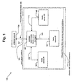
    According to another aspect of the invention, a blade server with load balancing using spare link bandwidth, comprises:
    • a server including a blade server manager, two or more blade servers, and a common backplane;
    • a network interface for communicating with an external network; and
    • two or more blade server interfaces for communicating between the blade server manager and each blade server;
       wherein said blade server manager allocates data received from said external network to each blade server based on embedded capacity utilization data transmitted by each blade server to the blade server manager that is embedded in spare link bandwidth on said interface between the blade server manager and each of said blade servers.
    Advantageously, said embedded capacity utilization data information is data representing blade server CPU percent utilization.
    Advantageously, said embedded capacity utilization data represents blade server interrupt utilization.
    Advantageously, the blade server manager is operably coupled to an Ethernet network.
    Advantageously, the blade server manager is operably coupled to an external TCP/IP network.
    Advantageously, the blade server manager is operably coupled to an external network with a communications link having a data rate of 10 Gigabits per second.
    Advantageously, the blade server manager communicates with each blade server over a dedicated link having a data rate of 1 Gigabit/second.
    Advantageously, the blade server utilization information is embedded in frame alignment information.
    Advantageously, the embedded capacity information is represented with at least two symbols.
    Advantageously, the embedded capacity information is represented with expanded control characters.
    Advantageously, said blade server allocates data received from said external network to each blade server using a load balancing algorithm, and wherein said load balancing algorithm utilizes said embedded capacity utilization data.
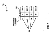
    Advantageously, said capacity utilization data is embedded in the inter packet gap.
    Advantageously, said capacity utilization data is embedded in the control words bounding a data word.
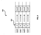
    These and other advantages, aspects and novel features of the present invention, as well as details of an illustrated embodiment thereof, will be more fully understood from the following description and drawings.
    BRIEF DESCRIPTION OF SEVERAL VIEWS OF THE DRAWINGS
    Fig. 1 is a diagram illustrating an embodiment of a communication system comprising a multi-server platform that performs load balancing, in accordance with various aspects of the present invention.
    Fig. 2 is a diagram illustrating an embodiment of a switch-blade comprising a load balancing algorithm and acting as a blade server manager within the multi-server platform of Fig. 1, in accordance with various aspects of the present invention.
    Fig. 3 is a flowchart illustrating an embodiment of a method to perform load balancing in the multi-server platform of Fig. 1, in accordance with various aspects of the present invention.
    FIG. 4 is a diagram illustrating an embodiment of a current multilane digital communication link.
    FIG. 5 is a diagram that illustrates an example of a XAUI parallel lane structure 200 for 10 gigabit (10G) BASE-X operation comprising four lanes.
    FIG. 6 is a diagram illustrating an embodiment of an enhanced encoding method specifically showing the encoding of lane alignment control characters /A/, in accordance with an embodiment of the invention.
    FIG. 7 is a diagram illustrating an embodiment of the enhanced encoding method of FIG. 6 specifically showing the encoding of a start-of-packet control character /S/ in accordance an embodiment ofthe present invention.
    FIG. 8 is a diagram illustrating an embodiment of the enhanced encoding method of FIG. 6 specifically showing the encoding of an end-of-packet control character /T/, in accordance with an embodiment of the present invention.
    FIG. 9 is a diagram illustrating an embodiment of the enhanced encoding method of FIG. 6 specifically showing the encoding of control characters in an inter-packet-gap, in accordance with an embodiment of the invention.
    FIG. 10 is a diagram illustrating an embodiment of the enhanced encoding method of FIG. 6 specifically showing the encoding of data words bounded by control characters, in accordance with an embodiment of the invention.
    FIG. 11 is a block diagram of an exemplary system 800 for encoding data in a multilane communication channel in accordance with an embodiment of the invention.
    FIG. 12 is a flowchart illustrating a capacity utilization algorithm that may be used with the invention.
    DETAILED DESCRIPTION OF THE INVENTION
    Certain embodiments of the present invention relate to load balancing among servers. In particular, certain embodiments of the present invention relate to providing blade server load balancing using spare link bandwidth in a multi-server platform having a single switch backplane.
    Fig. 1 is a diagram illustrating an embodiment of a communication system 100 comprising a multi-server platform 101 that performs load balancing, in accordance with various aspects of the present invention. The multi-server platform 101 comprises a chassis with a common backplane 111, a common switch-blade 102 acting as a blade server manager, a blade server #1 103, a blade server #2 104, and up to and including a blade server #N 105, where N may be any integer number.
    Each of the blade servers (#1 to #N) is a server on a single card or blade that plugs into the chassis with a common backplane 111. The chassis with a common backplane 111 provides a single installation box for the multiple blade servers (#1 to #N) and provides a common backplane interface (e.g., 108, 109, 110) between each blade server (e.g., 103, 104, 105) and the common switch-blade 102, where the common backplane interfaces (e.g., 108, 109, 110) are part of the common backplane 111. Such a configuration allows for an increased density of servers, easier management of the multiple servers (i.e., only one installation box needs to be serviced), scalability (i.e., more blade servers may be added over time), and better reliability.
    The common switch-blade 102 comprises N+1 interfaces and performs packet switching of data frames between the N blade servers and an external network 106, in accordance with an embodiment of the present invention. The common switch-blade 102 acts as a blade server manager by distributing data traffic to the server blades (#1 to #N) to balance the load of data traffic among the blade servers. The common switch-blade 102 interfaces to each of the N server blades over the common backplane 111 and also interfaces to the external network 106 (thus, N+1 interfaces).
    In accordance with an embodiment of the present invention, the switch-blade 102 communicates with each of the N blade servers independently over the common backplane 111. For example, blade server #1 103 communicates bi-directionally with the common switch-blade 102 via the common backplane interface 108. The blade server #2 104 communicates bi-directionally with the common switch-blade 102 via the common backplane interface 109. The blade server #N 105 communicates bi-directionally with the common switch-blade 102 via the common backplane interface 110. Each common backplane interface shares space on the backplane 111 but may be separate from the interface from the other blade servers.
    Fig. 2 is a diagram illustrating an embodiment of a switch-blade 200 comprising a load balancing algorithm 201 and acting as a blade server manager within the multi-server platform 101 of Fig. 1, in accordance with various aspects of the present invention. The switch-blade 200 receives blade server utilization information 202 from the various blade servers (e.g., blade server #1 to #N). The load balancing algorithm 201 within the switch-blade 200 uses the blade server utilization information to generate a load distribution 203. The load distribution 203 defines how the switch-blade 200 will currently distribute server data traffic among the blade servers within the multi-server platform 101.
    Fig. 3 is a flowchart illustrating an embodiment of a method 300 to perform load balancing in the multi-server platform 101 of Fig. 1, in accordance with various aspects of the present invention. In step 301, a first blade server transmits first utilization information, embedded in the spare link bandwidth of a first normal message, to a common switch-blade acting as a server manager. In step 302, a second blade server transmits second utilization information, embedded in the spare link bandwidth of a second normal message, to the common switch-blade acting as a server manager. In step 303, a third blade server transmits third utilization information, embedded in the spare link bandwidth of a third normal message, to the common switch-blade acting as a server manager. In step 304, the common switch-blade extracts the first, second, and third utilization information and performs load balancing of server traffic using a load balancing algorithm. In step 305, the common switch-blade forwards server traffic to at least one of the blade servers based on the results of the load balancing. The switch-blade, acting as the blade server manager, does not poll the blade servers for utilization information.
    Spare link bandwidth refers to any normally unutilized or underutilized bandwidth in a communication link between a blade server and a switch-blade acting as a server manager. For example, an overlay channel or frame alignment data.
    To embed utilization information in frame alignment data, reference is made to Figure 5. Fig. 5 shows a 10 G Base-X parallel lane structure, however other frame formats at higher or lower data rates may be used.
    Referring to FIG. 5, the XAUI parallel lane structure 500 may include a first lane (lane 0), a second lane (lane 1), a third lane (lane 2) and a fourth lane (lane 3). The XAUI parallel lane structure 500 depicts the end of a first data packet 501, an inter-packet-gap (IPG) or idle 502 and a first portion of a second data packet 503.
    The data word bytes in the data packets may be designated by /D/. The end-of-packet (EOP) word may be designated by the control character /T/ and may indicate the end of a data packet. The SOP (start-of-packet) word may be designated by the control character /S/ and may indicate the start of a data packet. The control character /K/ may indicate a comma and may be utilized for byte alignment. The control character /A/ may be utilized to indicate an alignment character that may be used for lane alignment. The control character /R/ may indicate a carrier extend and may be utilized to separate packets within a burst of packets. In certain instances, the control character /R/ may be utilized for code-group alignment. In this regard, the control character /R/ may be used to ensure proper code-group alignment of a first idle character occurring after a packet has been transmitted. The IPG or idle packet 502 preferably includes control characters such as /A/, /K/, and /R/. Consequently, the IPG or idle packet 502 does not include data characters.
    The various control characters in each of the parallel lanes, lane 0, lane 1, lane 2 and lane 3 may be part of the transmission protocol utilized by standardized 10G BASE-X transmission. In accordance with current 10G standards and protocols, there are 12 control characters or special code groups.
    FIG. 6 is a diagram 600 illustrating an embodiment of an enhanced encoding method specifically showing the encoding of lane alignment control characters /A/, in accordance with an embodiment of the invention. The lane alignment control character /A/ is a character that may appear in each of the lanes of a multi-lane transmission. The lane alignment control character /A/ may be utilized to align the parallel lanes with each other. In the case of a XAUI, the lane alignment control character may be utilized to align each of lane 0, lane 1, lane 2 and lane 3 with each other. Referring to FIG. 5, reference 504 illustrates an exemplary lane alignment characters in each of the XAUI lanes, lane 0, lane 1, lane 2 and lane 3.
    In an embodiment of the invention, the lane alignment control character may not be limited to the /A/ control character. Accordingly, the protocol may include a lane alignment character that may have at least two control characters. In this regard, the lane alignment character /A/ may be combined with a second control character and the combined control characters may be utilized for lane alignment. For example, in a case where a second lane alignment character such as /A'/ is utilized; then the /A/ and /A'/ characters may be simultaneously utilized for lane alignment. The /A'/ control character may be any one of the other available control characters in the protocol.
    In order to add encoded information, the control character /A/ may represent logic "1" and the control character /A'/ may represent logic "0". As a result, the two control characters /A/ and /A'/ may be utilized for lane alignment and as four additional bits of information that may be transmitted. Accordingly, the /A/ and the /A'/ control characters may utilize spare link bandwidth. The following table illustrates possible combinations for the control characters /A/, /A'/ for a XAUI.
    LANE 0 LANE 1 LANE 2 LANE 3
    0 /A/ /A/ /A/ /A/
    1 /A/ /A/ /A/ /A'/
    2 /A/ /A/ /A'/ /A/
    3 /A/ /A/ /A'/ /A'/
    4 /A/ /A'/ /A/ /A/
    5 /A/ /A'/ /A/ /A'/
    6 /A/ /A'/ /A'/ /A/
    7 /A/ /A'/ /A'/ /A'/
    8 /A'/ /A/ /A/ /A/
    9 /A'/ /A/ /A/ /A'/
    10 /A'/ /A/ /A'/ /A/
    11 /A'/ /A/ /A'/ /A'/
    12 /A'/ /A'/ /A/ /A/
    13 /A'/ /A'/ /A/ /A'/
    14 /A'/ /A'/ /A'/ /A/
    15 /A'/ /A'/ /A'/ /A'/
    For example, if the lane alignment characters transmitted in each lane are, lane 0: /A'/, lane 1: /A/, lane 2: /A/ and lane 3: /A'/, this may represent the four (4) bits of information 0, 1, 1, 0. With four (4) bits, there are 24 or 16 possible combinations that may be encoded, each of which may be utilized to represent a different unit of information. In one aspect of the invention, the four (4) bits of lane alignment control characters may be encoded in order to transmit status information or other system information, for example. The following table illustrates exemplary logic assignments for various combinations of control characters /A/, /A'/ for a XAUI as described in the table above.
    LANE 0 LANE 1 LANE 2 LANE 3
    0 1 1 1 1
    1 1 1 1 0
    2 1 1 0 1
    3 1 1 0 0
    4 1 0 1 1
    5 1 0 1 0
    6 1 0 0 1
    7 1 0 0 0
    8 0 1 1 1
    9 0 1 1 0
    10 0 1 0 1
    11 0 1 0 0
    12 0 0 1 1
    13 0 0 1 0
    14 0 0 0 1
    15 0 0 0 0
    The first exemplary combination or encoding, namely 0, which has lane 0: /A/, lane 1: /A/, lane 2: /A/ and lane 3: /A/ may represent the standard assignment for lane alignment. However, the remaining encoded combinations, namely 1 through 15, may represent expanded or additional assignments that may be utilized for communicating status or other system information.
    In another embodiment of the invention, a start-of-packet (SOP) control character, which may be represented as a /S/ control character, may also be encoded. FIG. 7 is a diagram 700 illustrating an embodiment of the enhanced encoding method of FIG. 6 specifically showing the encoding of a start-of-packet control character /S/ in accordance with the embodiment of the present invention. The start-of-packet control character /S/, may normally appear in lane 0 of a multilane communication channel structure. The start-of-packet control character /S/ may be utilized to signify the start of a next data packet, symbol or codeword by itself. Referring to FIG. 5, reference 506 depicts a start-of-packet control character /S/.
    In one embodiment of the invention, any control character in an existing control character set may be utilized to define an expanded or new start-of-packet control character that may represent the start of a next packet. Referring to FIG. 7, the expanded or new start-of-packet character may be represented by /Y/, for example. The expanded or new start-of-packet control character is referenced by 702. The expanded or new start-of-packet control character 702 may represent the start of a new packet and may be located or placed in the first lane, lane 0. The expanded start-of-packet control character 702 may be succeeded by or followed by data words, /D/, in each of the successive lanes, lane 1, lane 2 and lane 3. As a result, each unique control character /Y/ in a start-of-packet lane sequence may represent a different unit of information. For example, if there are 12 control characters in the control character set, then 11 additional units of information may be communicated as part of a start-of-packet control character. Notwithstanding, the additional units of information or expanded start-of-packet control characters may utilize spare link bandwidth.
    In another embodiment of the invention, an end-of-packet (EOP) control character, which may be represented as a /T/ control character, may also be encoded. FIG. 8 is a diagram 800 illustrating an embodiment of the enhanced encoding method of FIG. 6 specifically showing the encoding of an end-of-packet control character /T/, in accordance with an embodiment of the present invention. The end-of-packet control character /T/, may appear in any lane of a multi-lane structure and may be preceded by data words /D/ and/or followed by comma control characters /K/. The end-of-packet control character /T/ may also be utilized to define the end of a current data packet, symbol or control word all by itself. Although /T/ and /K/ control characters are illustrated in FIG. 8, the invention is not so limited and any other control characters in the existing control character set may be utilized.
    In accordance with an aspect of the invention, whenever an end-of-packet control character is preceded by data words /D/, subsequent end-of-packet control characters /T/ and/or comma control characters /K/ may be encoded as any available control character such as /Y/. For example, referring to FIG. 8, in a case where there are four (4) lanes and the end-of-packet sequence would be lane 0: /D/, lane 1: /D/, lane 2: /D/, and lane 3: /T/, as referenced by 802, then the /T/ in lane 3 may be encoded as any available control character /Y/. This may result in expanded or additional control characters that may provide additional units of information, which communicates status or other system information. The additional units of information or expanded end-of-packet control characters effectively utilize spare link bandwidth.
    Similarly, in instances where the end-of-packet sequence would be lane 0: /D/, lane 1: /D/, lane 2: /T/ and lane 3: /K, as referenced by 504, then the /T/ control character in lane 2 and the control character /K/ in lane 3 may be encoded with any combination of available control characters. This may result in expanded or additional control characters and may provide additional units of information that communicates status or other system information. The additional units of information or expanded end-of-packet control characters may utilize spare link bandwidth.
    Additionally, in instances where the end-of-packet sequence would be lane 0: D, lane 1: /T/, lane 2: /K/ and lane 3: /K/, as referenced by 806, then the /T/ control character in lane 1, the /K/ control character in lane 2, and the /K/ control character in lane 3 may be encoded with any combination of available control characters. In this regard, the sequence of two (2) /K/ control characters in lane 2 and lane 3 may be encoded as two (2) bits of additional information. For example, the two (2) /K/ control characters may be encoded as /K/ or /K'/ where /K'/ is a different control character from /K/ and may be one of the control characters in the existing control character set. In this manner, the /K/ control character may represent logic one (1) and the /K'/ may represent logic zero (0), thereby providing 2 bits of additional information in the EOP sequence. This may result in expanded or additional control characters and may provide additional units of information that communicates status or other system information. The additional units of information or expanded end-of-packet control characters may utilize spare link bandwidth.
    Finally, in instances where the end-of-packet sequence would be lane 0: /T/, lane 1: /K/, lane 2: /K/ and lane 3: /K/, as referenced by 508, then the sequence of three (3) /K/ control characters in lane 1, lane 2 and lane 3 may be encoded as three (3) bits of additional information. Again, this may result in expanded or additional control characters and may provide additional units of information that communicates status or other system information. The additional units of information or expanded end-of-packet control characters may utilize spare link bandwidth. For example, the three (3) /K/ control characters may be encoded as /K/ or /K'/ where /K'/ is a different control character from /K/ and may be one of the control characters in the existing control character set. In this manner, the /K/ control character may represent logic one (1) and the /K'/ may represent logic zero (0), thereby providing 3 bits of additional information in the EOP sequence. Other encoding schemes for this EOP sequence may be implemented without departing from the spirit or essence of the various embodiments of the present invention.
    Another embodiment of the invention may provide encoding of control characters in an idle or inter packet gap (IPG). FIG. 9 is a diagram 900 illustrating an embodiment of the enhanced encoding method of FIG. 6 specifically showing the encoding of control characters in an inter-packet-gap, in accordance with an embodiment of the invention. An inter-packet-gap or idle control character may occur between two data packets in a multilane communication channel. The inter-packet-gap may include comma control characters /K/ and carrier extend control characters /R/. In general, the inter-packet-gap control characters may be the same in any given column of a parallel multilane channel structure. Referring to FIG. 5, reference 508 depicts an idle or inter-packet-gap control character.
    Within an inter-packet-gap, a column of control characters across the parallel lanes of a multilane communication channel may be encoded using any combination of available control characters such as /Y/ in accordance with an embodiment of the invention. This may result in expanded or, additional inter-packet-gap control characters and may provide additional units of information that communicates status or other system information. The additional units of information or expanded inter-packet-gap control characters may utilize spare link bandwidth. In a further aspect of the invention, multiple columns of control characters within an inter-packet-gap may also be encoded in a similar manner to add even more information to the inter-packet-gap.
    Referring to FIG. 9, a column containing /K/ control characters 902, which may represent an inter-packet-gap or idle control character, may be encoded using any combination of control characters in the control character set. In this regard, /Y/ may represent a selected control character from the control character set. Possible combinations of the selected control character /Y/ may be represented by /Yi/, /Yj/, /Yk/ and /Yl/. Similarly, a column containing /R/ control characters 904, which may represent an inter-packet-gap or idle control character, may be encoded using any combination of control characters in the control character set. Accordingly, the /R/ control characters may be encoded using any possible combinations and may be represented by /Yi/, /Yj/, /Yk/ and /Yl/.
    Another embodiment of the invention may include the creation or generation of new columns of control characters, data words, code words and/or symbols, which may be placed in a multilane communication channel. FIG. 10 is a diagram 1000 illustrating an embodiment of the enhanced encoding method of FIG. 6 specifically showing the encoding of data words bounded by control characters, in accordance with an embodiment of the invention. In FIG. 10, newly created columns of control characters /Y/ and data words /D/ may be inserted into a multilane datastream for a communication channel.
    Referring to FIG. 10, three (3) exemplary configuration columns 1002, 1004 and 1006, of data words /D/ bounded by control characters /Y/ are illustrated. Expanded information may be encoded in the data words /D/ and may be bounded by control characters /Y/. The control characters /Y/ may be any combination of control characters in the control character set. Certain configurations of control characters /Y/ and data words /D/ may define specific types of communicated information. Accordingly, this may result in additional control characters and may provide additional units of information that may communicate status or other system information. The additional units of information or expanded control characters may utilize spare link bandwidth.
    For example, configuration column 1002 illustrates lane 0: /Y/, lane 1: /D/, lane 2: /Y/ and lane 3: Y and configuration column 1004 illustrates lane 0: /Y/, lane 1: /Y/, lane 2: /D/ and lane 3: /Y/. The configuration column 1006 having lane 0: /Y/, lane 1: /D/, lane 2: /D/ and lane 3: /Y/ may be generated to represent two bytes of status information such as error information. If each data word /D/ is 8 bits, for example, then each /D/ may be encoded to provide up to 28 or 256 different units of information. The newly encoded configuration columns 1002, 1004 and 1006 illustrate /D/ data words bounded by control characters /Y/. The new columns of added information may be inserted in the parallel lane structure of a multilane channel. In this regard, the new columns and added information may be inserted within data packets and/or within inter-packet-gaps, for example. The insertion of new columns of added information may result in the additional bytes being added to the parallel datastream in the multilane channel. However, the additional bytes are added to the parallel data stream such that the additional information that is carried by the additional bytes out weighs the overhead associated with the additional bytes.
    Other embodiments that may take advantage of spare link bandwidth may also be implemented. For example, the /K/ control character may comprise seven (7) fixed bits and three (3) don't care bits (xxx) according to 8B/10B encoding protocol, thereby resulting in a codeword of 0011111xxx. The protocol may be modified such that the three (3) don't care bits xxx, may be encoded with 23 or 8 different units of additional information in accordance with an embodiment of the present invention. Notwithstanding, although a XAUI is utilized to illustrate various embodiment or aspects of the invention, the enhanced encoding methods are applicable to other encoding schemes that may utilize multiple lanes, in accordance with various embodiments of the present invention.
    FIG. 11 is a block diagram of an exemplary system 1100 for encoding data in a multilane communication channel in accordance with an embodiment of the invention. The system 1100 may include an assignor 1102, a selector 1104, an encoder 1106, a controller 1108, a combiner 1110 and a generator 1112. Referring to FIG. 11, the generator 1112 may generate from existing control characters in a character set, expanded control characters utilized for controlling the data in each lane of the multilane communication channel. The controller 1108 may control at least one of the lanes of the multilane communication channel using at least one of the generated control characters. The selector 1104 may select a second control character from any other of the existing control characters if a first control character of the existing control characters is an alignment character. The combiner 1110 may combine the first control character with the second control character to generate a third control character. Each of the combination of the combined first control character and the second control character may represent the expanded control character. The assignor 1102 may assign a first logic level to the first control character and to assign a second logic level to the second control character. The first logic level and the second logic level is one of logic zero (0) and logic (1).
    In another aspect of the invention, the selector 1104 may select a second control character from any other of the existing control characters if a first control character of the existing control characters is a start-of-packet control character. The selected second control character may indicate the start of a packet. The controller 1108 may place the second control character in a first lane of the multilane communication channel. The controller 1108 may also determine which lane of the multilane communication channel contains an end-of-packet control character.
    The selector 1104 may select at least one other control character from the existing control character set if the end-of-packet control character is preceded by at least one control character in a lane of the multilane communication channel. The encoder 1106 may encode the selected at least one other control character as the end-of-packet control character. The selector 1104 may select at least one other control character from the existing control character set if the end-of-packet control character is succeeded by at least one comma control character in a lane of the multilane communication channel. The encoder 1106 may encode the selected control character as the comma control character. The generator 1112 may generate combinations of the encoded control character. The assignor 1102 may assign a unique value to each of the generated combinations of the encoded control character. Each of the assigned unique value may represent an expanded control character.
    In another aspect of the invention, the controller 1108 may determine at least one lane of the multilane communication channel that has an inter-packet-gap control character. The selector 1104 may select any combination of control characters from the existing control character set. The encoder 1106 may encode a column of the multilane communication channel corresponding to the determined lane with the selected any combination of control characters. The generator 1112 may generate at least one column bearing, for example a data word, bounded by control characters selected from the existing control character set. The encoder 1106 may encode at least a first lane and a last lane of at least one column of the multilane communication channel with the control characters selected from the existing control character set. In accordance with the various embodiments of the invention, the expanded control character may utilizing spare link bandwidth. The existing control characters may be a configuration character, an idle character or an encapsulation character, for example.
    In another embodiment of the invention, the /S/ control character may be further employed to utilize unused bandwidth. In this regard, the /S/ control character may not be limited to lane 0, but may be utilized in other lanes as well. For example, in a four (4) lane XAUI arrangement, the /S/ control character may occur in lanes 1, 2 and/or 3. Accordingly, in the four (4) lane XAUI system, there would be two (2) additional bits of information that may be passed depending on the lane in which lane the /S/ control character is located. For example, lane 0 may be represented by binary 00, lane 1 by binary 01, lane 2 by binary 10 and lane 3 by binary 11.
    Further description of the foregoing spare bandwidth technique is described in U.S. Patent Application Number 10/454,012, (Attorney Docket No. 14215US02), owned by the present assignee, and incorporated herein by reference. An alternate method of utilizing spare link bandwidth is described in U.S. Patent Application No. 10/454,273 (Attorney Docket No. 14219US02), also assigned to the owner of this patent application. That technique embeds information by coding the opposite sign of running disparity than what would normally be expected on an 8B10B or other coding algorithm. The reversed coding is detected as a "1" or "0" at the word level and can be combined over a series of words to generate additional control signals without consuming bandwidth
    An example or load balancing will now be described. Referring to Fig. 1, blade server #1 103, in the process of transmitting a message to the common switch-blade 102, may transmit its utilization information embedded within the spare link bandwidth of the message.
    In accordance with various embodiments of the present invention, utilization information may comprise blade server CPU percent utilization, blade server interrupt utilization, or any other load indicators that may be gathered from a hardware point-of-view from a blade server. In accordance with another embodiment of the present invention, utilization information may comprise the number of active sessions currently being serviced by a blade server.
    In one embodiment, hardware information corresponding to blade server utilization is gathered within each blade server and transmitted to the switch-blade in real time. In such an embodiment, the load balancing algorithm 201 may continuously update the load distribution 203, establishing maximum efficiency of the blade servers within the multi-server platform 101. An algorithm that could be used is shown in Figure 12, where the amount of load allocated to each blade is determined by taking the ratio of excess percent CPU availability for each blade divided by the sum of excess CPU capacity for all available blades.
    In accordance with an embodiment of the present invention, the multiple blade servers (#1 to #N) may each provide a plurality of functions via the external network 106. Alternatively, each of the multiple blade servers (#1 to #N) may be dedicated to providing a different, specific function via the external network 106.
    In summary, a method and system provides blade server load balancing using spare link bandwidth in a multi-server platform having a single switch backplane. A load balancing algorithm within a switch-blade, acting as a blade server manager, is used to generate a load distribution of server traffic based on utilization information provided by the blade servers. The utilization information is conveyed from the blade servers to the switch-blade by embedding the utilization information in the spare link bandwidth of messages communicated between the blade servers and the switch-blade in the course of normal operation. The embedded utilization information does not add significantly to the load on the servers.
    While the invention has been described with reference to certain embodiments, it will be understood by those skilled in the art that various changes may be made and equivalents may be substituted without departing from the scope of the invention. In addition, many modifications may be made to adapt a particular situation or material to the teachings of the invention without departing from its scope. Therefore, it is intended that the invention not be limited to the particular embodiment disclosed, but that the invention will include all embodiments falling within the scope of the appended claims.

    Claims (10)

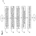
    1. A method for providing blade server load balancing using spare link bandwidth in a multi-server platform having a common backplane, comprising:
      a. receiving digital information on a digital communications link at a blade server manager;
      b. receiving capacity utilization information embedded in spare link bandwidth from a plurality of blade servers operably coupled to the blade server manager;
      c. selecting a blade server to receive said digital information based on the received capacity utilization information; and
      d. forwarding the received digital information to the selected blade server.
    2. The method of claim 1, wherein said embedded capacity utilization information is data representing blade server CPU percent utilization.
    3. The method of claim 1, wherein said embedded capacity utilization information is data representing blade server interrupt utilization.
    4. The method of claim 1, wherein the blade server manager is operably coupled to an Ethernet network.
    5. The method of claim 1, wherein the blade server manager is operably coupled to an external network.
    6. The method of claim 1, wherein the blade server manager is operably coupled to an external network at a link data rate of 10 Gigabits per second.
    7. The method of claim 1, wherein the blade server manager communicates with each blade server over a dedicated link.
    8. The method of claim 7, wherein the data rate of the dedicated link is 1 Gigabit/second.
    9. The method of claim 1, wherein the blade server utilization information is embedded in frame alignment information.
    10. A blade server with load balancing using spare link bandwidth, comprising:
      a server including a blade server manager, two or more blade servers, and a common backplane;
      a network interface for communicating with an external network; and
      two or more blade server interfaces for communicating between the blade server manager and each blade server;
         wherein said blade server manager allocates data received from said external network to each blade server based on embedded capacity utilization data transmitted by each blade server to the blade server manager that is embedded in spare link bandwidth on said interface between the blade server manager and each of said blade servers.
    EP04009904A 2003-06-04 2004-04-26 Method and system to provide blade server load balancing using spare link bandwidth Expired - Fee Related EP1484888B1 (en)

    Applications Claiming Priority (6)

    Application Number Priority Date Filing Date Title
    US10/454,273 US6859154B2 (en) 2003-02-12 2003-06-04 Method to overlay a secondary communication channel onto an encoded primary communication channel
    US10/454,012 US7463651B2 (en) 2003-02-12 2003-06-04 Method and system for exploiting spare link bandwidth in a multilane communication channel
    US454273 2003-06-04
    US454012 2003-06-04
    US10/665,648 US7835363B2 (en) 2003-02-12 2003-09-19 Method and system to provide blade server load balancing using spare link bandwidth
    US665648 2003-09-19

    Publications (3)

    Publication Number Publication Date
    EP1484888A2 true EP1484888A2 (en) 2004-12-08
    EP1484888A3 EP1484888A3 (en) 2006-03-29
    EP1484888B1 EP1484888B1 (en) 2007-12-12

    Family

    ID=33162970

    Family Applications (1)

    Application Number Title Priority Date Filing Date
    EP04009904A Expired - Fee Related EP1484888B1 (en) 2003-06-04 2004-04-26 Method and system to provide blade server load balancing using spare link bandwidth

    Country Status (3)

    Country Link
    US (2) US7835363B2 (en)
    EP (1) EP1484888B1 (en)
    DE (1) DE602004010571T2 (en)

    Families Citing this family (57)

    * Cited by examiner, † Cited by third party
    Publication number Priority date Publication date Assignee Title
    US20060031448A1 (en) * 2004-08-03 2006-02-09 International Business Machines Corp. On demand server blades
    US7675854B2 (en) 2006-02-21 2010-03-09 A10 Networks, Inc. System and method for an adaptive TCP SYN cookie with time validation
    US8437352B2 (en) * 2006-05-30 2013-05-07 Broadcom Corporation Method and system for power control based on application awareness in a packet network switch
    US7778275B2 (en) * 2006-09-29 2010-08-17 International Business Machines Corporation Method for dynamically allocating network adapters to communication channels for a multi-partition computer system
    US8312507B2 (en) 2006-10-17 2012-11-13 A10 Networks, Inc. System and method to apply network traffic policy to an application session
    US8584199B1 (en) 2006-10-17 2013-11-12 A10 Networks, Inc. System and method to apply a packet routing policy to an application session
    US7945647B2 (en) * 2007-12-10 2011-05-17 Oracle America, Inc. Method and system for creating a virtual network path
    US7962587B2 (en) * 2007-12-10 2011-06-14 Oracle America, Inc. Method and system for enforcing resource constraints for virtual machines across migration
    US7984123B2 (en) * 2007-12-10 2011-07-19 Oracle America, Inc. Method and system for reconfiguring a virtual network path
    US8095661B2 (en) * 2007-12-10 2012-01-10 Oracle America, Inc. Method and system for scaling applications on a blade chassis
    US8370530B2 (en) * 2007-12-10 2013-02-05 Oracle America, Inc. Method and system for controlling network traffic in a blade chassis
    US8086739B2 (en) * 2007-12-10 2011-12-27 Oracle America, Inc. Method and system for monitoring virtual wires
    US7965714B2 (en) * 2008-02-29 2011-06-21 Oracle America, Inc. Method and system for offloading network processing
    US7970951B2 (en) * 2008-02-29 2011-06-28 Oracle America, Inc. Method and system for media-based data transfer
    US7944923B2 (en) * 2008-03-24 2011-05-17 Oracle America, Inc. Method and system for classifying network traffic
    US7826359B2 (en) * 2008-03-24 2010-11-02 Oracle America, Inc. Method and system for load balancing using queued packet information
    US20090307399A1 (en) * 2008-06-10 2009-12-10 Accusys. Inc. Job-base structure using process as data processing and transmitting unit
    US7941539B2 (en) * 2008-06-30 2011-05-10 Oracle America, Inc. Method and system for creating a virtual router in a blade chassis to maintain connectivity
    US8739179B2 (en) * 2008-06-30 2014-05-27 Oracle America Inc. Method and system for low-overhead data transfer
    CN101938368A (en) * 2009-06-30 2011-01-05 国际商业机器公司 Virtual machine manager in blade server system and virtual machine processing method
    US9960967B2 (en) * 2009-10-21 2018-05-01 A10 Networks, Inc. Determining an application delivery server based on geo-location information
    US9215275B2 (en) 2010-09-30 2015-12-15 A10 Networks, Inc. System and method to balance servers based on server load status
    US9609052B2 (en) 2010-12-02 2017-03-28 A10 Networks, Inc. Distributing application traffic to servers based on dynamic service response time
    US9858241B2 (en) 2013-11-05 2018-01-02 Oracle International Corporation System and method for supporting optimized buffer utilization for packet processing in a networking device
    US8634415B2 (en) 2011-02-16 2014-01-21 Oracle International Corporation Method and system for routing network traffic for a blade server
    US8897154B2 (en) 2011-10-24 2014-11-25 A10 Networks, Inc. Combining stateless and stateful server load balancing
    US9386088B2 (en) 2011-11-29 2016-07-05 A10 Networks, Inc. Accelerating service processing using fast path TCP
    US9094364B2 (en) 2011-12-23 2015-07-28 A10 Networks, Inc. Methods to manage services over a service gateway
    US10044582B2 (en) 2012-01-28 2018-08-07 A10 Networks, Inc. Generating secure name records
    US8953451B2 (en) * 2012-06-14 2015-02-10 The Boeing Company Apparatus, methods, and systems for character set surveying of network traffic
    US8782221B2 (en) 2012-07-05 2014-07-15 A10 Networks, Inc. Method to allocate buffer for TCP proxy session based on dynamic network conditions
    JP5984552B2 (en) * 2012-07-20 2016-09-06 キヤノン株式会社 Load balancing system, load balancing system control method, and computer program
    US20140025800A1 (en) * 2012-07-23 2014-01-23 Radisys Corporation Systems and methods for multi-blade load balancing
    US9843484B2 (en) 2012-09-25 2017-12-12 A10 Networks, Inc. Graceful scaling in software driven networks
    US10021174B2 (en) 2012-09-25 2018-07-10 A10 Networks, Inc. Distributing service sessions
    WO2014052099A2 (en) 2012-09-25 2014-04-03 A10 Networks, Inc. Load distribution in data networks
    US10002141B2 (en) 2012-09-25 2018-06-19 A10 Networks, Inc. Distributed database in software driven networks
    US9106561B2 (en) 2012-12-06 2015-08-11 A10 Networks, Inc. Configuration of a virtual service network
    US9338225B2 (en) 2012-12-06 2016-05-10 A10 Networks, Inc. Forwarding policies on a virtual service network
    US9531846B2 (en) 2013-01-23 2016-12-27 A10 Networks, Inc. Reducing buffer usage for TCP proxy session based on delayed acknowledgement
    US9900252B2 (en) 2013-03-08 2018-02-20 A10 Networks, Inc. Application delivery controller and global server load balancer
    US9124495B2 (en) * 2013-03-11 2015-09-01 Dell Products L.P. System and method for automatic provisioning of stacked switches
    US9992107B2 (en) 2013-03-15 2018-06-05 A10 Networks, Inc. Processing data packets using a policy based network path
    US10027761B2 (en) 2013-05-03 2018-07-17 A10 Networks, Inc. Facilitating a secure 3 party network session by a network device
    WO2014179753A2 (en) 2013-05-03 2014-11-06 A10 Networks, Inc. Facilitating secure network traffic by an application delivery controller
    US9489327B2 (en) 2013-11-05 2016-11-08 Oracle International Corporation System and method for supporting an efficient packet processing model in a network environment
    US10230770B2 (en) 2013-12-02 2019-03-12 A10 Networks, Inc. Network proxy layer for policy-based application proxies
    US9942152B2 (en) 2014-03-25 2018-04-10 A10 Networks, Inc. Forwarding data packets using a service-based forwarding policy
    US9942162B2 (en) 2014-03-31 2018-04-10 A10 Networks, Inc. Active application response delay time
    US9906422B2 (en) 2014-05-16 2018-02-27 A10 Networks, Inc. Distributed system to determine a server's health
    US10129122B2 (en) 2014-06-03 2018-11-13 A10 Networks, Inc. User defined objects for network devices
    US9992229B2 (en) 2014-06-03 2018-06-05 A10 Networks, Inc. Programming a data network device using user defined scripts with licenses
    US9986061B2 (en) 2014-06-03 2018-05-29 A10 Networks, Inc. Programming a data network device using user defined scripts
    US10721150B2 (en) * 2015-05-12 2020-07-21 Hewlett Packard Enterprise Development Lp Server discrete side information
    US10581976B2 (en) 2015-08-12 2020-03-03 A10 Networks, Inc. Transmission control of protocol state exchange for dynamic stateful service insertion
    US10243791B2 (en) 2015-08-13 2019-03-26 A10 Networks, Inc. Automated adjustment of subscriber policies
    WO2019148482A1 (en) * 2018-02-05 2019-08-08 Cisco Technology, Inc. Configurable storage server with multiple sockets

    Citations (2)

    * Cited by examiner, † Cited by third party
    Publication number Priority date Publication date Assignee Title
    GB2016247A (en) * 1978-03-04 1979-09-19 Plessey Co Ltd Improved method of signalling supervisory information in digital line transmission systems
    US20030097428A1 (en) * 2001-10-26 2003-05-22 Kambiz Afkhami Internet server appliance platform with flexible integrated suite of server resources and content delivery capabilities supporting continuous data flow demands and bursty demands

    Family Cites Families (27)

    * Cited by examiner, † Cited by third party
    Publication number Priority date Publication date Assignee Title
    US6728748B1 (en) * 1998-12-01 2004-04-27 Network Appliance, Inc. Method and apparatus for policy based class of service and adaptive service level management within the context of an internet and intranet
    US6988138B1 (en) * 1999-06-30 2006-01-17 Blackboard Inc. Internet-based education support system and methods
    US7062556B1 (en) * 1999-11-22 2006-06-13 Motorola, Inc. Load balancing method in a communication network
    US6570855B1 (en) * 1999-12-30 2003-05-27 At&T Corp. Automatic call manager traffic gate feature
    US7054943B1 (en) * 2000-04-28 2006-05-30 International Business Machines Corporation Method and apparatus for dynamically adjusting resources assigned to plurality of customers, for meeting service level agreements (slas) with minimal resources, and allowing common pools of resources to be used across plural customers on a demand basis
    US20020107962A1 (en) * 2000-11-07 2002-08-08 Richter Roger K. Single chassis network endpoint system with network processor for load balancing
    US6810018B2 (en) * 2000-12-07 2004-10-26 Nortel Networks Limited Method and apparatus for load balancing in CDMA/HDR networks
    JP4230673B2 (en) * 2001-02-22 2009-02-25 富士通株式会社 Service management device
    US7339786B2 (en) * 2001-03-05 2008-03-04 Intel Corporation Modular server architecture with Ethernet routed across a backplane utilizing an integrated Ethernet switch module
    US20020188718A1 (en) * 2001-05-04 2002-12-12 Rlx Technologies, Inc. Console information storage system and method
    US7245632B2 (en) * 2001-08-10 2007-07-17 Sun Microsystems, Inc. External storage for modular computer systems
    US20040054656A1 (en) * 2001-08-31 2004-03-18 Arkivio, Inc. Techniques for balancing capacity utilization in a storage environment
    US7284067B2 (en) * 2002-02-20 2007-10-16 Hewlett-Packard Development Company, L.P. Method for integrated load balancing among peer servers
    TWI231424B (en) * 2002-06-28 2005-04-21 Quanta Comp Inc Management and preparation system of blade server
    US7765299B2 (en) * 2002-09-16 2010-07-27 Hewlett-Packard Development Company, L.P. Dynamic adaptive server provisioning for blade architectures
    US7243145B1 (en) * 2002-09-30 2007-07-10 Electronic Data Systems Corporation Generation of computer resource utilization data per computer application
    US20040081104A1 (en) * 2002-10-29 2004-04-29 Weimin Pan Method and system for network switch configuration
    TWM242781U (en) * 2002-11-25 2004-09-01 Quanta Comp Inc Blade server management system with auxiliary management structure
    US7219183B2 (en) * 2003-01-21 2007-05-15 Nextio, Inc. Switching apparatus and method for providing shared I/O within a load-store fabric
    US7046668B2 (en) * 2003-01-21 2006-05-16 Pettey Christopher J Method and apparatus for shared I/O in a load/store fabric
    US7519057B2 (en) * 2003-02-18 2009-04-14 Broadcom Corporation System and method for communicating using a multiserver platform
    US7480720B2 (en) * 2003-06-25 2009-01-20 International Business Machines Corporation Method and system for load balancing switch modules in a server system and a computer system utilizing the same
    US7912954B1 (en) * 2003-06-27 2011-03-22 Oesterreicher Richard T System and method for digital media server load balancing
    US7443857B1 (en) * 2003-07-09 2008-10-28 Cisco Technology Inc. Connection routing based on link utilization
    US20060167886A1 (en) * 2004-11-22 2006-07-27 International Business Machines Corporation System and method for transmitting data from a storage medium to a user-defined cluster of local and remote server blades
    US9141435B2 (en) * 2007-07-30 2015-09-22 Sybase, Inc. System and methodology providing workload management in database cluster
    US20100223364A1 (en) * 2009-02-27 2010-09-02 Yottaa Inc System and method for network traffic management and load balancing

    Patent Citations (2)

    * Cited by examiner, † Cited by third party
    Publication number Priority date Publication date Assignee Title
    GB2016247A (en) * 1978-03-04 1979-09-19 Plessey Co Ltd Improved method of signalling supervisory information in digital line transmission systems
    US20030097428A1 (en) * 2001-10-26 2003-05-22 Kambiz Afkhami Internet server appliance platform with flexible integrated suite of server resources and content delivery capabilities supporting continuous data flow demands and bursty demands

    Non-Patent Citations (2)

    * Cited by examiner, † Cited by third party
    Title
    "10-GIGABIT ETHERNET TAKES ON SONET" EDN ELECTRICAL DESIGN NEWS, CAHNERS PUBLISHING CO. NEWTON, MASSACHUSETTS, US, vol. 46, no. 14, 21 June 2001 (2001-06-21), pages 81-82,84,86, XP001162653 ISSN: 0012-7515 *
    "The next step in server load balancing" WHITE PAPER ALTEON WEB SYSTEMS, X, November 1999 (1999-11), pages 1-15,I, XP002974311 *

    Also Published As

    Publication number Publication date
    EP1484888A3 (en) 2006-03-29
    US20040202182A1 (en) 2004-10-14
    US8102874B2 (en) 2012-01-24
    US7835363B2 (en) 2010-11-16
    DE602004010571T2 (en) 2008-12-11
    DE602004010571D1 (en) 2008-01-24
    EP1484888B1 (en) 2007-12-12
    US20110066729A1 (en) 2011-03-17

    Similar Documents

    Publication Publication Date Title
    US7835363B2 (en) Method and system to provide blade server load balancing using spare link bandwidth
    US8089899B2 (en) System and method for communicating using a multiserver platform
    EP1695517B1 (en) Method and architecture for optical networking between server and storage area networks
    CN100348000C (en) Methods and apparatus for encapsulating a frame for transmission in a storage area network
    EP2202921B1 (en) A data storage method, a management server, a storage equipment and system
    EP2433395B1 (en) Achieving about an equal number of active links across chassis in a virtual port-channel environment
    US7804855B2 (en) Method and system for exploiting spare link bandwidth in a multilane communication channel
    CN1965540B (en) Method, system and apparatus for detecting support for a protocol defining supplemental headers
    KR101717296B1 (en) Ethernet apparatus and method for operating multiple lane selectively
    CN101674152B (en) Method, device and system for data transmission based on forward error correction (FEC)
    WO2015035618A1 (en) Data transmission method and apparatus
    KR101250538B1 (en) Ethernet Device and Lane Operation Method
    JPH0799830B2 (en) Communication protocol for a statistical data multiplexer incorporated in a wide area network.
    CN104683015A (en) Unmanned aerial vehicle ground station bus system
    CN100531215C (en) Method for realizing multiple network device link aggregation
    CN107683592A (en) Data processing method, device and system
    US7257758B1 (en) Stumping mechanism
    CN1589548A (en) An interface and related methods for implementing dynamic channelization in an Ethernet architecture
    CN111385156B (en) sFlow flow sampling method, device and system
    US6370152B1 (en) Distributed SNMP agent for frame relay switching network
    CN1227916C (en) Device and method for improving load distribution in signaling network
    CN101159694A (en) Method of preventing fail fragment reassembly of IP sharing distributed system
    CN1705297A (en) Sectionalization exchange for controlling system power mode
    US8964547B1 (en) Credit announcement
    Eltraify et al. Energy efficient passive optical data centre networks

    Legal Events

    Date Code Title Description
    PUAI Public reference made under article 153(3) epc to a published international application that has entered the european phase

    Free format text: ORIGINAL CODE: 0009012

    AK Designated contracting states

    Kind code of ref document: A2

    Designated state(s): AT BE BG CH CY CZ DE DK EE ES FI FR GB GR HU IE IT LI LU MC NL PL PT RO SE SI SK TR

    AX Request for extension of the european patent

    Extension state: AL HR LT LV MK

    PUAL Search report despatched

    Free format text: ORIGINAL CODE: 0009013

    AK Designated contracting states

    Kind code of ref document: A3

    Designated state(s): AT BE BG CH CY CZ DE DK EE ES FI FR GB GR HU IE IT LI LU MC NL PL PT RO SE SI SK TR

    AX Request for extension of the european patent

    Extension state: AL HR LT LV MK

    17P Request for examination filed

    Effective date: 20060929

    17Q First examination report despatched

    Effective date: 20061027

    AKX Designation fees paid

    Designated state(s): DE FR GB

    RAP1 Party data changed (applicant data changed or rights of an application transferred)

    Owner name: BROADCOM CORPORATION

    GRAP Despatch of communication of intention to grant a patent

    Free format text: ORIGINAL CODE: EPIDOSNIGR1

    GRAS Grant fee paid

    Free format text: ORIGINAL CODE: EPIDOSNIGR3

    GRAA (expected) grant

    Free format text: ORIGINAL CODE: 0009210

    AK Designated contracting states

    Kind code of ref document: B1

    Designated state(s): DE FR GB

    REG Reference to a national code

    Ref country code: GB

    Ref legal event code: FG4D

    REF Corresponds to:

    Ref document number: 602004010571

    Country of ref document: DE

    Date of ref document: 20080124

    Kind code of ref document: P

    ET Fr: translation filed
    PLBE No opposition filed within time limit

    Free format text: ORIGINAL CODE: 0009261

    STAA Information on the status of an ep patent application or granted ep patent

    Free format text: STATUS: NO OPPOSITION FILED WITHIN TIME LIMIT

    26N No opposition filed

    Effective date: 20080915

    PGFP Annual fee paid to national office [announced via postgrant information from national office to epo]

    Ref country code: GB

    Payment date: 20130422

    Year of fee payment: 10

    PGFP Annual fee paid to national office [announced via postgrant information from national office to epo]

    Ref country code: FR

    Payment date: 20130523

    Year of fee payment: 10

    GBPC Gb: european patent ceased through non-payment of renewal fee

    Effective date: 20140426

    REG Reference to a national code

    Ref country code: FR

    Ref legal event code: ST

    Effective date: 20141231

    PG25 Lapsed in a contracting state [announced via postgrant information from national office to epo]

    Ref country code: GB

    Free format text: LAPSE BECAUSE OF NON-PAYMENT OF DUE FEES

    Effective date: 20140426

    PG25 Lapsed in a contracting state [announced via postgrant information from national office to epo]

    Ref country code: FR

    Free format text: LAPSE BECAUSE OF NON-PAYMENT OF DUE FEES

    Effective date: 20140430

    REG Reference to a national code

    Ref country code: DE

    Ref legal event code: R082

    Ref document number: 602004010571

    Country of ref document: DE

    Representative=s name: BOSCH JEHLE PATENTANWALTSGESELLSCHAFT MBH, DE

    Ref country code: DE

    Ref legal event code: R081

    Ref document number: 602004010571

    Country of ref document: DE

    Owner name: AVAGO TECHNOLOGIES INTERNATIONAL SALES PTE. LT, SG

    Free format text: FORMER OWNER: BROADCOM CORP., IRVINE, CALIF., US

    Ref country code: DE

    Ref legal event code: R081

    Ref document number: 602004010571

    Country of ref document: DE

    Owner name: AVAGO TECHNOLOGIES GENERAL IP (SINGAPORE) PTE., SG

    Free format text: FORMER OWNER: BROADCOM CORP., IRVINE, CALIF., US

    REG Reference to a national code

    Ref country code: DE

    Ref legal event code: R082

    Ref document number: 602004010571

    Country of ref document: DE

    Representative=s name: BOSCH JEHLE PATENTANWALTSGESELLSCHAFT MBH, DE

    Ref country code: DE

    Ref legal event code: R081

    Ref document number: 602004010571

    Country of ref document: DE

    Owner name: AVAGO TECHNOLOGIES INTERNATIONAL SALES PTE. LT, SG

    Free format text: FORMER OWNER: AVAGO TECHNOLOGIES GENERAL IP (SINGAPORE) PTE. LTD., SINGAPORE, SG

    PGFP Annual fee paid to national office [announced via postgrant information from national office to epo]

    Ref country code: DE

    Payment date: 20210409

    Year of fee payment: 18

    REG Reference to a national code

    Ref country code: DE

    Ref legal event code: R079

    Ref document number: 602004010571

    Country of ref document: DE

    Free format text: PREVIOUS MAIN CLASS: H04L0029060000

    Ipc: H04L0065000000

    REG Reference to a national code

    Ref country code: DE

    Ref legal event code: R119

    Ref document number: 602004010571

    Country of ref document: DE

    PG25 Lapsed in a contracting state [announced via postgrant information from national office to epo]

    Ref country code: DE

    Free format text: LAPSE BECAUSE OF NON-PAYMENT OF DUE FEES

    Effective date: 20221103