EP1491823A1 - Rabbet mounted gas turbine combustor - Google Patents
Rabbet mounted gas turbine combustor Download PDFInfo
- Publication number
- EP1491823A1 EP1491823A1 EP20040252427 EP04252427A EP1491823A1 EP 1491823 A1 EP1491823 A1 EP 1491823A1 EP 20040252427 EP20040252427 EP 20040252427 EP 04252427 A EP04252427 A EP 04252427A EP 1491823 A1 EP1491823 A1 EP 1491823A1
- Authority
- EP
- European Patent Office
- Prior art keywords
- rabbet
- flange
- shell
- liner
- casing
- Prior art date
- Legal status (The legal status is an assumption and is not a legal conclusion. Google has not performed a legal analysis and makes no representation as to the accuracy of the status listed.)
- Granted
Links
Images
Classifications
-
- F—MECHANICAL ENGINEERING; LIGHTING; HEATING; WEAPONS; BLASTING
- F23—COMBUSTION APPARATUS; COMBUSTION PROCESSES
- F23M—CASINGS, LININGS, WALLS OR DOORS SPECIALLY ADAPTED FOR COMBUSTION CHAMBERS, e.g. FIREBRIDGES; DEVICES FOR DEFLECTING AIR, FLAMES OR COMBUSTION PRODUCTS IN COMBUSTION CHAMBERS; SAFETY ARRANGEMENTS SPECIALLY ADAPTED FOR COMBUSTION APPARATUS; DETAILS OF COMBUSTION CHAMBERS, NOT OTHERWISE PROVIDED FOR
- F23M5/00—Casings; Linings; Walls
- F23M5/04—Supports for linings
-
- F—MECHANICAL ENGINEERING; LIGHTING; HEATING; WEAPONS; BLASTING
- F23—COMBUSTION APPARATUS; COMBUSTION PROCESSES
- F23R—GENERATING COMBUSTION PRODUCTS OF HIGH PRESSURE OR HIGH VELOCITY, e.g. GAS-TURBINE COMBUSTION CHAMBERS
- F23R3/00—Continuous combustion chambers using liquid or gaseous fuel
- F23R3/002—Wall structures
-
- F—MECHANICAL ENGINEERING; LIGHTING; HEATING; WEAPONS; BLASTING
- F23—COMBUSTION APPARATUS; COMBUSTION PROCESSES
- F23R—GENERATING COMBUSTION PRODUCTS OF HIGH PRESSURE OR HIGH VELOCITY, e.g. GAS-TURBINE COMBUSTION CHAMBERS
- F23R3/00—Continuous combustion chambers using liquid or gaseous fuel
- F23R3/42—Continuous combustion chambers using liquid or gaseous fuel characterised by the arrangement or form of the flame tubes or combustion chambers
- F23R3/60—Support structures; Attaching or mounting means
-
- F—MECHANICAL ENGINEERING; LIGHTING; HEATING; WEAPONS; BLASTING
- F23—COMBUSTION APPARATUS; COMBUSTION PROCESSES
- F23R—GENERATING COMBUSTION PRODUCTS OF HIGH PRESSURE OR HIGH VELOCITY, e.g. GAS-TURBINE COMBUSTION CHAMBERS
- F23R2900/00—Special features of, or arrangements for continuous combustion chambers; Combustion processes therefor
- F23R2900/00017—Assembling combustion chamber liners or subparts
Definitions
- the present invention relates generally to gas turbine engines, and, more specifically, to combustors therein.
- a typical gas turbine engine includes a multistage compressor for pressurizing air which is mixed with fuel in a combustor for generating hot combustion gases.
- the gases flow through a high pressure turbine (HPT) which extracts energy for powering the compressor.
- HPT high pressure turbine
- LPT low pressure turbine extracts additional energy for providing output work, such as powering a fan in a turbofan aircraft engine application, or providing output shaft power in land-based or marine applications.
- a turbine engine for powering a military vehicle such as a main battle tank
- the size and weight of the engine must be as small as possible, which correspondingly increases the difficulty of integrating the various engine components for maximizing performance, efficiency, and life.
- one engine being developed includes an exhaust heat exchanger or recuperator which uses the hot combustion gases discharged from the turbines for additionally heating the pressurized air discharged from the compressor for increasing engine efficiency.
- this hot pressurized air must also be used for cooling the combustor components themselves which further increases the complexity of the combustor design.
- the liners must therefore be suitably mounted to their supports for accommodating differential thermal movement therebetween, while also minimizing undesirable leakage of the pressurized air coolant.
- the liners must be mounted concentrically with each other and with the supports to minimize undesirable variations in temperature distribution, both radially and circumferentially around the outlet end of the combustor as represented by the conventionally known pattern and profile factors.
- Liner alignment or concentricity with the turbine is therefore an important design objective for an annular combustor, and is rendered particularly more difficult due to the double-wall liner configuration.
- Liner alignment affects all aspects of the combustor performance including cooling thereof, dilution of the combustion gases, and turbine performance.
- liner mounting to the supports must minimize thermally induced stress therein for ensuring maximum life of the combustor during operation.
- the development combustor disclosed above was designed for proof-of-concept and lacked production features for the intended service life requirements in the tank application. For example, studs were welded to the outer liner and simply bolted to the outer support for mounting the outer liner thereto. In turn, the entire combustor was aft-mounted to a support casing through the outer combustor wall. This bolted design inherently fails to accommodate differential thermal movement between the liner and outer support and results in considerable thermal stresses during operation.
- a combustor includes an outer wall and an inner liner joined to an inner shell in turn mounted to an inner casing.
- the casing includes a first rabbet at an end flange in which is mounted a corresponding flange of the inner shell.
- the inner shell also includes a second rabbet which receives an end flange of the inner liner.
- the inner shell is trapped in the first rabbet by an inner retainer.
- the inner liner is trapped in the surrounding second rabbet for aft-mounting the liner and shell to the inner casing.
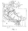
- FIG. 1 Illustrated schematically in Figure 1 is a gas turbine engine 10 configured for powering a land-based vehicle, for example.
- the engine is axisymmetrical about a longitudinal or axial centerline axis 12, and includes multistage compressor 14 for pressurizing air 16 during operation.
- the pressurized air is discharged from the compressor and mixed with fuel 18 in an annular combustor 20 for generating hot combustion gases 22.
- the combustion gases are discharged from the combustor into a high pressure turbine (HPT) 24 which extracts energy therefrom for powering the compressor.
- the high pressure turbine is conventional and includes an annular stator nozzle at the discharge end of the combustor which directs the combustion gases through a row of high pressure turbine rotor blades extending outwardly from a supporting rotor disk joined by a shaft to the compressor rotor.
- a low pressure turbine (LPT) 26 follows the HPT and conventionally includes one or more stator nozzles and rotor blade rows for extracting additional energy for powering an output driveshaft, which in turn drives a transmission in the exemplary military tank application.
- An exhaust heat exchanger or recuperator 28 receives the combustion gases from the LPT for in turn further heating the compressor discharge air suitably channeled thereto. The so-heated compressor discharge air is then channeled to the combustor for undergoing the combustion process, as well as providing cooling of the combustor components.
- the annular combustor illustrated in Figure 1 is axisymmetrical about the engine centerline axis 12 and is structurally supported from an annular outer casing 30.
- the combustor is an assembly of components further including an annular radially inner casing, or combustor case, 32 including a first or aft flange 34 and a second or forward flange 36 at opposite ends thereof, and annular header 38 disposed therebetween closely adjoining the casing forward flange 36.
- the inner casing 32 also includes an annular first rabbet 40 extending circumferentially around the casing aft flange 34 facing axially aft and radially outwardly.
- the combustor further includes an annular, radially inner shell or support 42 disposed concentrically around the inner casing 32 and supported thereon.
- the inner shell includes a first or aft flange 44 and a second or forward flange 46 at opposite ends thereof, and an annular dome 48 therebetween closely adjoining the shell forward flange 46.
- the inner shell also includes an annular radially outer second rabbet 50 around the shell aft flange 44, with the shell aft flange itself being seated in the first rabbet 40.
- the combustor illustrated in Figure 1 also includes an annular outer combustor wall 52 suitably mounted to the shell forward flange 46 by a plurality of fasteners such as bolts.
- the outer wall 52 is an assembly of an outer shell and an outer combustion liner having suitable apertures therethrough for channeling the pressurized air 16 as a coolant therethrough during operation.
- An annular, radially inner combustion liner 54 includes a first or aft flange 56 and a second or forward flange 58 at opposite ends thereof which mount the inner liner to the inner shell in another double-wall configuration spaced radially inwardly from the outer wall 52 to define therebetween an annular combustion chamber 60.
- the forward flange 58 of the inner liner includes a radially outwardly facing slot that receives an L-shaped split retainer ring 62 which also seats in an axial groove at the junction of the inner shell and its dome for free-floating the inner liner to the inner shell to permit unrestrained differential thermal expansion and contraction relative to the aft end of the inner liner and shell.
- the liner aft flange 56 as best illustrated in Figure 2, is in the form of a radially inwardly extending rim which is seated in the second rabbet 50 of the inner shell.
- the shell aft flange 44 is also in the form of a radially inwardly extending rim which is seated in the first rabbet 40.
- both the outer and inner double-walls and dome 48 defining the combustion chamber 60 are commonly supported from the combustor case or inner shell 42, which in turn is supported on the aft flange 34 of the inner casing 32 for providing aft-mounting of the combustor, with a corresponding loadpath to the supporting outer casing 30.
- the forward flange 36 of the inner casing is suitably mounted to a corresponding flange of the outer casing using a row of fasteners such as bolts.
- the shell aft flange 44 is simply seated in the first rabbet 40 with a suitably close tolerance therebetween, and similarly, the liner aft flange 56 is simply seated in the second rabbet 50 with a suitably close tolerance therebetween.
- An annular inner retainer 64 is fixedly joined to the casing aft flange 34 by bolt fasteners for example to axially trap the shell aft flange 44 around the first rabbet 40.
- annular outer retainer 66 is fixedly joined to the second rabbet 50 to axially trap the liner aft flange 56 around the second rabbet.
- the outer retainer 66 may be a full ring with a single split, or may be a ring segmented in multiple sections from three to about eight.
- the individual retainer segments may be suitably tack welded to the second rabbet 50 on the aft side of the liner aft flange 56 opposite to the forward radial shoulder of the second rabbet.
- the inner retainer 64 is preferably a full ring disposed on the aft side of the shell aft flange 44 opposite to the radial shoulder of the first rabbet 40 on the forward side of the shell aft flange.
- the inner liner 54 illustrated in Figure 1 is concentrically mounted around its supporting shell 42 which in turn is concentrically mounted around its supporting casing 32 which in turn is suspended by the outer casing 30.
- the inner liner 54 and its supporting inner shell 42 are both mounted at their aft ends to the casing aft flange 34 for permitting differential thermal expansion and contraction relative thereto during operation.
- combustion gases 22 are generated in the combustion chamber 60 and effect a decreasing temperature gradient from the liners to their supporting shells and in turn to the supporting inner casing 32.
- These components are annular or conical elements subject to both radial expansion and contraction as well as axial expansion and contraction.
- the inner liner 54 and the inner shell 42 are free to expand and contract relative to their supported aft ends and thereby experience relatively low thermal stress due to differential thermal movement therebetween. And, the aft mounting of the inner liner and its supporting shell ensures concentricity thereof relative to the engine
- the inner retainer 64 forms a portion of the support for the turbine nozzle of the HPT 24. Accordingly, the inner combustion liner 54 and the turbine nozzle are commonly supported from the casing aft flange 34, and concentricity therebetween may be maintained for ensuring accurate radial alignment of the combustion gases 22 as they flow between the stator vanes of the turbine nozzle during operation.
- the various components of the combustor should be suitably mounted for maintaining the various alignments required therebetween for enhanced performance of the combustor during operation.
- the concentricity of both outer and inner combustion liners with the HP turbine nozzle is a significant design objective.
- the casing header 38 includes a row of fuel injectors 68 suitably mounted through corresponding apertures 70 therein.
- the dome 48 includes a row of air swirlers 72 suitably mounted in corresponding apertures 74 in the dome.
- the fuel injectors and air swirlers may have any conventional configuration, with the fuel injectors being configured for injecting fuel through the center of the corresponding swirler, which typically includes two rows of counterrotating radial vanes which swirl the pressurized compressor air in two counterrotating streams around the injected fuel for atomization thereof for efficient combustion in the combustion chamber.
- a plurality of tabs or keys 76 as shown in Figures 2 and 3 are mounted in respective grooves or slots 78 between the shell aft flange 44 and the first rabbet 40 for maintaining circumferential alignment between the apertures 70,74 in the header 38 and dome 48 for corresponding alignment of the fuel injectors in their respective air swirlers.
- the keys 76 are fixedly mounted, by brazing for example, in the corresponding mounting grooves formed in the radially inner surface of the shell aft flange 44.
- the complementary alignment slots 78 are disposed in the first rabbet 40 and face radially outwardly in radial alignment with the corresponding keys 76.
- the keys 76 could be integrally formed with the shell aft flange 44, it is more practical and economical to separately manufacture the keys and fixedly mount them in the flange.
- Three keys 76 are used in the preferred embodiment and have an unequal circumferential spacing varying slightly from 120 degrees apart to ensure that the inner shell 42 may be assembled on the inner casing 32 in a single orientation, which in turn ensures proper alignment of the fuel injectors and air swirlers in their corresponding apertures.
- the three keys extend radially outwardly from the engine centerline axis and permit unrestrained differential thermal expansion and contraction in the radial direction.
- each key 76 is preferably designed for withstanding the maximum expected external loads due to vehicle movement without failing.
- the multiple keys therefore provide failsafe redundancy in load support, as well as suitably clocking or indexing the circumferential alignment between the inner shell 42 and the inner casing 32.
- the combustor preferably also includes a plurality of axial pins 80 mounted in respective cylindrical sockets 82 between the liner aft flange 56 and the second rabbet 50 for maintaining circumferential alignment between conventional dilution holes 84 provided in the inner liner.
- Both outer and inner combustion liners include patterns of inclined film cooling holes for channeling a portion of the compressed air 16 for cooling thereof in a conventional manner.
- both liners also include relatively large dilution holes, such as the row of dilution holes 84 illustrated in the inner liner of Figures 1 and 3.
- the dilution holes are circumferentially aligned with the corresponding fuel injectors and swirlers for minimizing hot streaks from the combustion gases discharged therefrom during operation. Alignment of the dilution holes with the corresponding swirlers is therefore required for proper performance of the combustor, and such alignment is effected by the complementary mating pins 80 in their alignment sockets 82.
- the pins 80 are preferably fixedly joined, by welding for example, to the inner shell 42 to extend radially outwardly over the second rabbet 50 from the forward shoulder thereof.
- the sockets 82 are cylindrical apertures disposed axially through the liner aft flange 56 in axial alignment with the corresponding pins.
- three pins are disposed with unequal circumferential spacing varying slightly from 120 degrees apart around the circumference of the forward shoulder of the second rabbet 50.
- the dilution holes 84 provided in the inner liner 54 may be maintained in circumferential alignment with the corresponding air swirlers.
- the unequally spaced pins 80 ensure one and only one proper assembly position of the inner liner on its supporting inner casing.
- the simple pins 80 may be used instead of the stronger keys 76 at this location. Accordingly, the pins 80 may have any suitable configuration for their location at the second rabbet 50 and for the expected loads thereat. Similarly, the keys 76 may have any suitable configuration for the expected loads at the first rabbet 40.
- the inner casing 32 is generally toroidal due to its C-shaped axial section.
- the header 38 portion of the inner casing is thusly disposed axially forward of both the first and second end flanges 34,36 thereof for receiving the inner shell 42 forward of the casing aft flange 34.
- the inner shell 42 is spaced radially outwardly from the inner casing 32 to define an annulus 86 therebetween through which the pressurized air 16 is channeled for flow through the inner wall of the combustor.
- the shell aft flange 44 preferably includes a row of axial bypass holes 88 disposed in flow communication with the casing annulus 86 for channeling a portion of the air 16 axially therethrough.
- the inner retainer 64 is conveniently provided by a suitable portion of the annular support for the HP nozzle.
- the retainer includes a radially inner portion which is suitably fastened by bolts to the casing aft flange 34, and includes a radially outer portion in which the stator nozzle is mounted.
- the inner retainer 64 as illustrated in Figure 2 also includes a row of generally axially disposed apertures 90 extending through the radially outer flange thereof, and circumferentially aligned with respective ones of the bypass holes 88.
- the pressurized air 16 may be metered through the bypass holes 88 for providing pressurization in the annular cavity defined between the inner band of the HP nozzle and its inner support.
- the small radial flange of the inner retainer 64 through which the apertures 90 are provided is an otherwise conventional feature for supporting a leaf seal (not shown).
- the dual rabbet mounting of the inner liner 54 and the inner shell 42 to the cooperating inner casing 32 enjoys simplicity of construction and the several benefits described above including concentricity of the combustion chamber with the HP nozzle while maintaining accurate circumferential alignment of the simply mounted inner liner and inner shell.
- the shell aft flange 44 is radially supported on the first rabbet 40 and axially trapped between the inner retainer 34 on one side and the shoulder of the first rabbet on the other side.
- the manufacturing tolerances and clearances between these components may be relatively small for the direct trapping of the shell aft flange in the first rabbet without the need or desire for additional sealing members thereat.
- the liner aft flange 56 is radially supported around the second rabbet 50 and axially trapped between the outer retainer 66 on one side thereof and the shoulder of the second rabbet 50 on the opposite side thereof.
- the manufacturing tolerances or clearances may be relatively small for directly trapping the liner aft flange 56 around the second rabbet without the need or desire for additional sealing members thereat.
- Figure 3 illustrates schematically the assembly and corresponding disassembly of the inner combustor wall.
- the inner liner 54 itself is initially axially mounted around the inner shell 42 to seat the liner aft flange 56 in the second rabbet 50, while circumferentially aligning the several pins 80 and their mating sockets 82.
- the outer retainer 66 may then be conveniently welded in position on the exposed ledge of the second rabbet 50 following seating of the liner aft flange 56 in axial abutment against the rabbet shoulder.
- the inner shell 42 is then axially mounted around the inner casing 32 to seat the shell aft flange 44 in the first rabbet 40, while circumferentially aligning the mating keys 76 and slots 78.
- the inner retainer 64 may then be axially mounted on the exposed shelf of the first rabbet 40 to axially trap the shell aft flange 44 in the first rabbet.
- the assembly process may be reversed.
- the inner retainer 64 is axially removed from the inner casing 32 after the fasteners are disassembled.
- the inner shell 42 and inner liner 54 supported thereon may then be axially removed from the inner casing 32.
- the outer retainer 66 may then be removed from the second rabbet 50, by grinding of the tack welds for example, to then release the inner liner 54 from the second rabbet.
- the inner liner may then be removed from the inner shell and replaced with a new inner liner, with the assembly process then being repeated to reassemble the combustor with a new outer retainer 66, and either the originally used or new inner retainer 64.
- the double rabbet aft mounting of the annular combustor illustrated in Figure 1 therefore enjoys various advantages in simplicity, assembly, disassembly, and maintenance repair. Concentricity between the combustion chamber and the HP nozzle and alignment of the fuel injectors, air swirlers, and dilution holes are ensured. And, pressurization air may be conveniently channeled through the bypass holes.
Abstract
Description
- The present invention relates generally to gas turbine engines, and, more specifically, to combustors therein.
- A typical gas turbine engine includes a multistage compressor for pressurizing air which is mixed with fuel in a combustor for generating hot combustion gases. The gases flow through a high pressure turbine (HPT) which extracts energy for powering the compressor. A low pressure turbine (LPT) extracts additional energy for providing output work, such as powering a fan in a turbofan aircraft engine application, or providing output shaft power in land-based or marine applications.
- In designing a turbine engine for powering a military vehicle, such as a main battle tank, the size and weight of the engine must be as small as possible, which correspondingly increases the difficulty of integrating the various engine components for maximizing performance, efficiency, and life. For example, one engine being developed includes an exhaust heat exchanger or recuperator which uses the hot combustion gases discharged from the turbines for additionally heating the pressurized air discharged from the compressor for increasing engine efficiency. However, this hot pressurized air must also be used for cooling the combustor components themselves which further increases the complexity of the combustor design.
- In the last two decades, a double-wall combustor design underwent considerable development effort which did not lead to commercial production thereof. Radially outer and inner combustion liners were supported from corresponding radially outer and inner annular supports. Compressor discharge air was channeled through apertures in the supports for impingement cooling the outer surfaces of the liners. The spent impingement air was then channeled through film cooling and dilution holes in the liners for cooling the liners themselves, as well as providing dilution air for the combustion gases generated in the annular combustion chamber.
- A consequence of the double wall combustor design is the inherent difference in operating temperature between the liners and the surrounding supports. Differential operating temperatures result in differential thermal expansion and contraction of the combustor components. Such differential thermal movement occurs both axially and radially, as well as during steady state or static operation and during transient operation of the engine as power is increased and decreased.
- The liners must therefore be suitably mounted to their supports for accommodating differential thermal movement therebetween, while also minimizing undesirable leakage of the pressurized air coolant. The liners must be mounted concentrically with each other and with the supports to minimize undesirable variations in temperature distribution, both radially and circumferentially around the outlet end of the combustor as represented by the conventionally known pattern and profile factors.
- Liner alignment or concentricity with the turbine is therefore an important design objective for an annular combustor, and is rendered particularly more difficult due to the double-wall liner configuration. Liner alignment affects all aspects of the combustor performance including cooling thereof, dilution of the combustion gases, and turbine performance. And, liner mounting to the supports must minimize thermally induced stress therein for ensuring maximum life of the combustor during operation.
- The development combustor disclosed above was designed for proof-of-concept and lacked production features for the intended service life requirements in the tank application. For example, studs were welded to the outer liner and simply bolted to the outer support for mounting the outer liner thereto. In turn, the entire combustor was aft-mounted to a support casing through the outer combustor wall. This bolted design inherently fails to accommodate differential thermal movement between the liner and outer support and results in considerable thermal stresses during operation.
- Accordingly, it is desired to provide an improved double-wall combustor design for accommodating differential thermal movement during operation while maintaining concentricity of liner support.
- According to the present invention, a combustor includes an outer wall and an inner liner joined to an inner shell in turn mounted to an inner casing. The casing includes a first rabbet at an end flange in which is mounted a corresponding flange of the inner shell. The inner shell also includes a second rabbet which receives an end flange of the inner liner. The inner shell is trapped in the first rabbet by an inner retainer. And, the inner liner is trapped in the surrounding second rabbet for aft-mounting the liner and shell to the inner casing.
- The invention, in accordance with preferred and exemplary embodiments, together with further objects and advantages thereof, is more particularly described in the following detailed description taken in conjunction with the accompanying drawings in which:
- Figure 1 is a partly sectional, schematic view of a gas turbine engine having one embodiment of a double-wall combustor for powering a land-based vehicle.
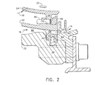
- Figure 2 is an enlarged axial sectional view of the aft end of the combustor inner wall illustrated in Figure 1.
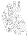
- Figure 3 is an exploded view of the combustor aft inner mount illustrated in Figure 2 showing schematically the assembly thereof, and disassembly for repair.
- Illustrated schematically in Figure 1 is a
gas turbine engine 10 configured for powering a land-based vehicle, for example. The engine is axisymmetrical about a longitudinal oraxial centerline axis 12, and includesmultistage compressor 14 for pressurizingair 16 during operation. The pressurized air is discharged from the compressor and mixed withfuel 18 in anannular combustor 20 for generatinghot combustion gases 22. - The combustion gases are discharged from the combustor into a high pressure turbine (HPT) 24 which extracts energy therefrom for powering the compressor. The high pressure turbine is conventional and includes an annular stator nozzle at the discharge end of the combustor which directs the combustion gases through a row of high pressure turbine rotor blades extending outwardly from a supporting rotor disk joined by a shaft to the compressor rotor.
- A low pressure turbine (LPT) 26 follows the HPT and conventionally includes one or more stator nozzles and rotor blade rows for extracting additional energy for powering an output driveshaft, which in turn drives a transmission in the exemplary military tank application.
- An exhaust heat exchanger or
recuperator 28 receives the combustion gases from the LPT for in turn further heating the compressor discharge air suitably channeled thereto. The so-heated compressor discharge air is then channeled to the combustor for undergoing the combustion process, as well as providing cooling of the combustor components. - The annular combustor illustrated in Figure 1 is axisymmetrical about the
engine centerline axis 12 and is structurally supported from an annularouter casing 30. The combustor is an assembly of components further including an annular radially inner casing, or combustor case, 32 including a first oraft flange 34 and a second orforward flange 36 at opposite ends thereof, andannular header 38 disposed therebetween closely adjoining the casingforward flange 36. - As shown in more detail in Figures 2 and 3, the
inner casing 32 also includes an annularfirst rabbet 40 extending circumferentially around thecasing aft flange 34 facing axially aft and radially outwardly. - Referring again to Figure 1, the combustor further includes an annular, radially inner shell or
support 42 disposed concentrically around theinner casing 32 and supported thereon. The inner shell includes a first oraft flange 44 and a second orforward flange 46 at opposite ends thereof, and anannular dome 48 therebetween closely adjoining the shellforward flange 46. Again shown in more detail in Figures 2 and 3, the inner shell also includes an annular radially outersecond rabbet 50 around theshell aft flange 44, with the shell aft flange itself being seated in thefirst rabbet 40. - The combustor illustrated in Figure 1 also includes an annular
outer combustor wall 52 suitably mounted to the shellforward flange 46 by a plurality of fasteners such as bolts. Theouter wall 52 is an assembly of an outer shell and an outer combustion liner having suitable apertures therethrough for channeling the pressurizedair 16 as a coolant therethrough during operation. - An annular, radially
inner combustion liner 54 includes a first oraft flange 56 and a second orforward flange 58 at opposite ends thereof which mount the inner liner to the inner shell in another double-wall configuration spaced radially inwardly from theouter wall 52 to define therebetween anannular combustion chamber 60. - The
forward flange 58 of the inner liner includes a radially outwardly facing slot that receives an L-shapedsplit retainer ring 62 which also seats in an axial groove at the junction of the inner shell and its dome for free-floating the inner liner to the inner shell to permit unrestrained differential thermal expansion and contraction relative to the aft end of the inner liner and shell. Theliner aft flange 56, as best illustrated in Figure 2, is in the form of a radially inwardly extending rim which is seated in thesecond rabbet 50 of the inner shell. In turn, theshell aft flange 44 is also in the form of a radially inwardly extending rim which is seated in thefirst rabbet 40. - Accordingly, both the outer and inner double-walls and
dome 48 defining thecombustion chamber 60 are commonly supported from the combustor case orinner shell 42, which in turn is supported on theaft flange 34 of theinner casing 32 for providing aft-mounting of the combustor, with a corresponding loadpath to the supportingouter casing 30. Theforward flange 36 of the inner casing is suitably mounted to a corresponding flange of the outer casing using a row of fasteners such as bolts. - As shown in Figure 2, the
shell aft flange 44 is simply seated in thefirst rabbet 40 with a suitably close tolerance therebetween, and similarly, theliner aft flange 56 is simply seated in thesecond rabbet 50 with a suitably close tolerance therebetween. An annularinner retainer 64 is fixedly joined to thecasing aft flange 34 by bolt fasteners for example to axially trap theshell aft flange 44 around thefirst rabbet 40. - Similarly, an annular
outer retainer 66 is fixedly joined to thesecond rabbet 50 to axially trap theliner aft flange 56 around the second rabbet. Theouter retainer 66 may be a full ring with a single split, or may be a ring segmented in multiple sections from three to about eight. The individual retainer segments may be suitably tack welded to thesecond rabbet 50 on the aft side of theliner aft flange 56 opposite to the forward radial shoulder of the second rabbet. Similarly, theinner retainer 64 is preferably a full ring disposed on the aft side of theshell aft flange 44 opposite to the radial shoulder of thefirst rabbet 40 on the forward side of the shell aft flange. - In this way, the
inner liner 54 illustrated in Figure 1 is concentrically mounted around its supportingshell 42 which in turn is concentrically mounted around its supportingcasing 32 which in turn is suspended by theouter casing 30. Theinner liner 54 and its supportinginner shell 42 are both mounted at their aft ends to thecasing aft flange 34 for permitting differential thermal expansion and contraction relative thereto during operation. - In operation,
combustion gases 22 are generated in thecombustion chamber 60 and effect a decreasing temperature gradient from the liners to their supporting shells and in turn to the supportinginner casing 32. These components are annular or conical elements subject to both radial expansion and contraction as well as axial expansion and contraction. Theinner liner 54 and theinner shell 42 are free to expand and contract relative to their supported aft ends and thereby experience relatively low thermal stress due to differential thermal movement therebetween. And, the aft mounting of the inner liner and its supporting shell ensures concentricity thereof relative to the engine - As illustrated in Figure 1, the
inner retainer 64 forms a portion of the support for the turbine nozzle of theHPT 24. Accordingly, theinner combustion liner 54 and the turbine nozzle are commonly supported from the casing aftflange 34, and concentricity therebetween may be maintained for ensuring accurate radial alignment of thecombustion gases 22 as they flow between the stator vanes of the turbine nozzle during operation. - The various components of the combustor should be suitably mounted for maintaining the various alignments required therebetween for enhanced performance of the combustor during operation. The concentricity of both outer and inner combustion liners with the HP turbine nozzle is a significant design objective.
- Additional alignment is also required in the combustor. In particular, the
casing header 38 includes a row offuel injectors 68 suitably mounted throughcorresponding apertures 70 therein. Correspondingly, thedome 48 includes a row ofair swirlers 72 suitably mounted in correspondingapertures 74 in the dome. - The fuel injectors and air swirlers may have any conventional configuration, with the fuel injectors being configured for injecting fuel through the center of the corresponding swirler, which typically includes two rows of counterrotating radial vanes which swirl the pressurized compressor air in two counterrotating streams around the injected fuel for atomization thereof for efficient combustion in the combustion chamber.
- Since the
fuel injectors 70 are mounted in thecasing header 38 and theair swirlers 72 are mounted in thecasing dome 48, suitable alignment therebetween is required for proper assembly and performance of the combustor. - More specifically, a plurality of tabs or
keys 76 as shown in Figures 2 and 3 are mounted in respective grooves orslots 78 between the shell aftflange 44 and thefirst rabbet 40 for maintaining circumferential alignment between theapertures header 38 anddome 48 for corresponding alignment of the fuel injectors in their respective air swirlers. - In a preferred embodiment, the
keys 76 are fixedly mounted, by brazing for example, in the corresponding mounting grooves formed in the radially inner surface of the shell aftflange 44. And, thecomplementary alignment slots 78 are disposed in thefirst rabbet 40 and face radially outwardly in radial alignment with thecorresponding keys 76. Although thekeys 76 could be integrally formed with the shell aftflange 44, it is more practical and economical to separately manufacture the keys and fixedly mount them in the flange. - Three
keys 76 are used in the preferred embodiment and have an unequal circumferential spacing varying slightly from 120 degrees apart to ensure that theinner shell 42 may be assembled on theinner casing 32 in a single orientation, which in turn ensures proper alignment of the fuel injectors and air swirlers in their corresponding apertures. The three keys extend radially outwardly from the engine centerline axis and permit unrestrained differential thermal expansion and contraction in the radial direction. - The keys may be suitably small for preventing relative rotation between the inner shell and its supporting inner casing, yet may be sized sufficiently large for accommodating external loads expected in the vehicle mounting of the gas turbine engine. A vehicle-mounted engine is subject to various shock loads as the vehicle travels over rough terrain, especially in a high speed military application. Accordingly, each key 76 is preferably designed for withstanding the maximum expected external loads due to vehicle movement without failing. The multiple keys therefore provide failsafe redundancy in load support, as well as suitably clocking or indexing the circumferential alignment between the
inner shell 42 and theinner casing 32. - As shown in Figures 2 and 3, the combustor preferably also includes a plurality of
axial pins 80 mounted in respectivecylindrical sockets 82 between the liner aftflange 56 and thesecond rabbet 50 for maintaining circumferential alignment between conventional dilution holes 84 provided in the inner liner. Both outer and inner combustion liners include patterns of inclined film cooling holes for channeling a portion of thecompressed air 16 for cooling thereof in a conventional manner. And, both liners also include relatively large dilution holes, such as the row of dilution holes 84 illustrated in the inner liner of Figures 1 and 3. - The dilution holes are circumferentially aligned with the corresponding fuel injectors and swirlers for minimizing hot streaks from the combustion gases discharged therefrom during operation. Alignment of the dilution holes with the corresponding swirlers is therefore required for proper performance of the combustor, and such alignment is effected by the complementary mating pins 80 in their
alignment sockets 82. - As shown in Figures 2 and 3, the
pins 80 are preferably fixedly joined, by welding for example, to theinner shell 42 to extend radially outwardly over thesecond rabbet 50 from the forward shoulder thereof. Correspondingly, thesockets 82 are cylindrical apertures disposed axially through the liner aftflange 56 in axial alignment with the corresponding pins. - In the preferred embodiment, three pins are disposed with unequal circumferential spacing varying slightly from 120 degrees apart around the circumference of the forward shoulder of the
second rabbet 50. In this way, the dilution holes 84 provided in theinner liner 54 may be maintained in circumferential alignment with the corresponding air swirlers. The unequally spaced pins 80 ensure one and only one proper assembly position of the inner liner on its supporting inner casing. - Since the expected loads between the inner liner and its supporting casing are relatively low, the
simple pins 80 may be used instead of thestronger keys 76 at this location. Accordingly, thepins 80 may have any suitable configuration for their location at thesecond rabbet 50 and for the expected loads thereat. Similarly, thekeys 76 may have any suitable configuration for the expected loads at thefirst rabbet 40. - As initially illustrated in Figure 1, the
inner casing 32 is generally toroidal due to its C-shaped axial section. Theheader 38 portion of the inner casing is thusly disposed axially forward of both the first andsecond end flanges inner shell 42 forward of the casing aftflange 34. And, theinner shell 42 is spaced radially outwardly from theinner casing 32 to define anannulus 86 therebetween through which thepressurized air 16 is channeled for flow through the inner wall of the combustor. - As shown in Figures 2 and 3, the shell aft
flange 44 preferably includes a row of axial bypass holes 88 disposed in flow communication with thecasing annulus 86 for channeling a portion of theair 16 axially therethrough. - As indicated above, the
inner retainer 64 is conveniently provided by a suitable portion of the annular support for the HP nozzle. The retainer includes a radially inner portion which is suitably fastened by bolts to the casing aftflange 34, and includes a radially outer portion in which the stator nozzle is mounted. - The
inner retainer 64 as illustrated in Figure 2 also includes a row of generally axially disposedapertures 90 extending through the radially outer flange thereof, and circumferentially aligned with respective ones of the bypass holes 88. In this way, thepressurized air 16 may be metered through the bypass holes 88 for providing pressurization in the annular cavity defined between the inner band of the HP nozzle and its inner support. As shown in Figure 2, the small radial flange of theinner retainer 64 through which theapertures 90 are provided is an otherwise conventional feature for supporting a leaf seal (not shown). - The dual rabbet mounting of the
inner liner 54 and theinner shell 42 to the cooperatinginner casing 32 enjoys simplicity of construction and the several benefits described above including concentricity of the combustion chamber with the HP nozzle while maintaining accurate circumferential alignment of the simply mounted inner liner and inner shell. As shown in Figure 2, the shell aftflange 44 is radially supported on thefirst rabbet 40 and axially trapped between theinner retainer 34 on one side and the shoulder of the first rabbet on the other side. The manufacturing tolerances and clearances between these components may be relatively small for the direct trapping of the shell aft flange in the first rabbet without the need or desire for additional sealing members thereat. - Similarly, the liner aft
flange 56 is radially supported around thesecond rabbet 50 and axially trapped between theouter retainer 66 on one side thereof and the shoulder of thesecond rabbet 50 on the opposite side thereof. Again, the manufacturing tolerances or clearances may be relatively small for directly trapping the liner aftflange 56 around the second rabbet without the need or desire for additional sealing members thereat. - This nested duplex rabbet mounting of the combustor inner wall to the inner casing is relatively simple in configuration and enjoys the additional benefit of simple assembly, and disassembly for maintenance and repair. More specifically, Figure 3 illustrates schematically the assembly and corresponding disassembly of the inner combustor wall.
- The
inner liner 54 itself is initially axially mounted around theinner shell 42 to seat the liner aftflange 56 in thesecond rabbet 50, while circumferentially aligning theseveral pins 80 and theirmating sockets 82. - The
outer retainer 66 may then be conveniently welded in position on the exposed ledge of thesecond rabbet 50 following seating of the liner aftflange 56 in axial abutment against the rabbet shoulder. - The
inner shell 42, with the inner liner premounted thereon, is then axially mounted around theinner casing 32 to seat the shell aftflange 44 in thefirst rabbet 40, while circumferentially aligning themating keys 76 andslots 78. Theinner retainer 64 may then be axially mounted on the exposed shelf of thefirst rabbet 40 to axially trap the shell aftflange 44 in the first rabbet. - In order to repair the combustor, for example by replacing the
inner liner 54 thereof, the assembly process may be reversed. Theinner retainer 64 is axially removed from theinner casing 32 after the fasteners are disassembled. Theinner shell 42 andinner liner 54 supported thereon may then be axially removed from theinner casing 32. Theouter retainer 66 may then be removed from thesecond rabbet 50, by grinding of the tack welds for example, to then release theinner liner 54 from the second rabbet. - The inner liner may then be removed from the inner shell and replaced with a new inner liner, with the assembly process then being repeated to reassemble the combustor with a new
outer retainer 66, and either the originally used or newinner retainer 64. - The double rabbet aft mounting of the annular combustor illustrated in Figure 1 therefore enjoys various advantages in simplicity, assembly, disassembly, and maintenance repair. Concentricity between the combustion chamber and the HP nozzle and alignment of the fuel injectors, air swirlers, and dilution holes are ensured. And, pressurization air may be conveniently channeled through the bypass holes.
Claims (10)
- A combustor (20) comprising: an annular outer casing (30); an annular inner casing (32) including first and second flanges (34,36) at opposite ends with a header (38) therebetween, said first flange (34) having a first rabbet (40) circumferentially therearound, and said second flange (36) being fixedly supported from said outer casing (30); said header (38) including a row of fuel injectors (68) mounted through apertures (70) therein;
an annular inner shell (42) including first and second flanges (44,46) at opposite ends thereof with a dome (48) therebetween, and a radially outer second rabbet (50) around said first flange (44) thereof, with said shell first flange being seated in said first rabbet (40);
said dome (48) including a row of air swirlers (72) mounted in apertures (74) therein and receiving in circumferential alignment corresponding ones of said fuel injectors (68);
an annular inner combustion liner (54) including first and second flanges (56,58) at opposite ends, and said liner first flange (56) being seated around said second rabbet (50);
an annular outer combustor wall (52) mounted to said shell second flange; and an annular inner retainer (64) fixedly joined to said casing first flange (34) to axially trap said shell first flange (44) around said first rabbet (40). - A combustor according to claim 1 wherein said inner casing (32) is toroidal, with said header (38) being disposed axially forward of both said first and second flanges (34,36) thereof for receiving said inner shell forward of said casing first flange (34) to define an annulus (86) therebetween for channeling pressurized air therethrough.
- A combustor according to claim 2 further comprising a row of bypass holes (88) disposed through said shell first flange (44) in flow communication with said annulus (86).
- A combustor according to claim 3 wherein said inner retainer (64) includes a radially outer flange having a row of apertures (90) extending therethrough circumferentially aligned with respective ones of said bypass holes (88).
- A combustor according to claim 4 further comprising a plurality of keys (76) mounted in respective slots (78) between said shell first flange (44) and said first rabbet (40) for maintaining circumferential alignment between said fuel injectors (68) in said header (38) and said air swirlers (72) in said dome (48).
- A combustor according to claim 5 wherein: said inner liner (54) includes a row of dilution holes (84) for channeling dilution air therethrough; and
further comprising a plurality of pins (80) mounted in respective sockets (82) between said liner first flange (56) and said second rabbet (50) for maintaining circumferential alignment between said dilution holes (84) and said swirler apertures (74) in said dome (48). - A combustor according to claim 6 wherein: said keys (76) are fixedly mounted in said shell first flange (44), and said slots (78) are disposed in said first rabbet (40) in radial alignment therewith; and
said pins (80) are fixedly joined to said inner shell (42) radially outwardly of said second rabbet (50), and said sockets (82) are disposed in said liner first flange (56) in axial alignment therewith. - A combustor according to claim 7 further comprising an annular outer retainer (66) fixedly joined to said second rabbet (50) to axially trap said liner first flange (56) around said second rabbet.
- A method of assembling said combustor according to claim 8 comprising: axially mounting said inner liner (54) around inner shell (42) to seat said liner first flange (56) in said second rabbet (50), while circumferentially aligning said pins (80) and sockets (82);
axially mounting said inner shell (42) around said inner casing (32) to seat said shell first flange (44) in said first rabbet (40), while circumferentially aligning said keys (76) and slots (78);
fixedly joining said outer retainer (66) to said second rabbet (50) to axially trap said liner first flange (56) around said second rabbet; and
axially mounting said inner retainer (64) in said first rabbet (40) to axially trap said shell first flange (44) in said first rabbet. - A method of repairing said combustor according to claim 8 comprising:removing said inner retainer (64) from said inner casing (32);removing said inner shell (42) and liner (54) from said inner casing (32);removing said outer retainer (66) from said second rabbet (50) to release said inner liner (54);removing and replacing said inner liner (54) from said inner shell (42); and reassembling said replaced inner liner with said inner shell on said inner casing.
Applications Claiming Priority (2)
| Application Number | Priority Date | Filing Date | Title |
|---|---|---|---|
| US608609 | 1984-05-09 | ||
| US10/608,609 US7152411B2 (en) | 2003-06-27 | 2003-06-27 | Rabbet mounted combuster |
Publications (2)
| Publication Number | Publication Date |
|---|---|
| EP1491823A1 true EP1491823A1 (en) | 2004-12-29 |
| EP1491823B1 EP1491823B1 (en) | 2008-11-19 |
Family
ID=33418732
Family Applications (1)
| Application Number | Title | Priority Date | Filing Date |
|---|---|---|---|
| EP04252427A Expired - Fee Related EP1491823B1 (en) | 2003-06-27 | 2004-04-27 | Rabbet mounted gas turbine combustor |
Country Status (5)
| Country | Link |
|---|---|
| US (1) | US7152411B2 (en) |
| EP (1) | EP1491823B1 (en) |
| CN (1) | CN100565014C (en) |
| CA (1) | CA2464563C (en) |
| DE (1) | DE602004017813D1 (en) |
Cited By (5)
| Publication number | Priority date | Publication date | Assignee | Title |
|---|---|---|---|---|
| EP1493970A2 (en) | 2003-07-02 | 2005-01-05 | General Electric Company | Methods and apparatus for operating gas turbine engine combustors |
| EP1486732A3 (en) * | 2003-06-11 | 2012-08-22 | General Electric Company | Floating liner combustor |
| EP1921383A3 (en) * | 2006-11-10 | 2013-12-18 | General Electric Company | Combustor dome and methods of assembling such |
| EP2921778A1 (en) * | 2014-03-11 | 2015-09-23 | Rolls-Royce Deutschland Ltd & Co KG | Combustion chamber of a gas turbine |
| EP2918913B1 (en) * | 2014-03-11 | 2017-11-15 | Rolls-Royce Deutschland Ltd & Co KG | Combustion chamber of a gas turbine |
Families Citing this family (37)
| Publication number | Priority date | Publication date | Assignee | Title |
|---|---|---|---|---|
| CN1250906C (en) * | 2001-09-07 | 2006-04-12 | 阿尔斯托姆科技有限公司 | Damping arrangement for reducing combustion chamber pulsations in a gas turbine system |
| US7036316B2 (en) * | 2003-10-17 | 2006-05-02 | General Electric Company | Methods and apparatus for cooling turbine engine combustor exit temperatures |
| US7082770B2 (en) * | 2003-12-24 | 2006-08-01 | Martling Vincent C | Flow sleeve for a low NOx combustor |
| US20060231531A1 (en) * | 2005-04-13 | 2006-10-19 | General Electric Company | Weld prep joint for electron beam or laser welding |
| EP1744016A1 (en) * | 2005-07-11 | 2007-01-17 | Siemens Aktiengesellschaft | Hot gas conducting cover element, shaft protection shroud and gas turbine |
| US7559203B2 (en) * | 2005-09-16 | 2009-07-14 | Pratt & Whitney Canada Corp. | Cooled support boss for a combustor in a gas turbine engine |
| FR2899314B1 (en) * | 2006-03-30 | 2008-05-09 | Snecma Sa | DEVICE FOR INJECTING A MIXTURE OF AIR AND FUEL, COMBUSTION CHAMBER AND TURBOMACHINE HAVING SUCH A DEVICE |
| US8109098B2 (en) * | 2006-05-04 | 2012-02-07 | Siemens Energy, Inc. | Combustor liner for gas turbine engine |
| US8590313B2 (en) * | 2008-07-30 | 2013-11-26 | Rolls-Royce Corporation | Precision counter-swirl combustor |
| US8266914B2 (en) * | 2008-10-22 | 2012-09-18 | Pratt & Whitney Canada Corp. | Heat shield sealing for gas turbine engine combustor |
| US8863527B2 (en) * | 2009-04-30 | 2014-10-21 | Rolls-Royce Corporation | Combustor liner |
| US8429916B2 (en) * | 2009-11-23 | 2013-04-30 | Honeywell International Inc. | Dual walled combustors with improved liner seals |
| US8713945B2 (en) * | 2010-06-29 | 2014-05-06 | Nuovo Pignone S.P.A. | Liner aft end support mechanisms and spring loaded liner stop mechanisms |
| US9625153B2 (en) * | 2010-11-09 | 2017-04-18 | Opra Technologies B.V. | Low calorific fuel combustor for gas turbine |
| US8844260B2 (en) * | 2010-11-09 | 2014-09-30 | Opra Technologies B.V. | Low calorific fuel combustor for gas turbine |
| US8899051B2 (en) | 2010-12-30 | 2014-12-02 | Rolls-Royce Corporation | Gas turbine engine flange assembly including flow circuit |
| FR2976346B1 (en) * | 2011-06-08 | 2013-07-05 | Turbomeca | TURBOMACHINE ANNULAR COMBUSTION CHAMBER |
| US20130081397A1 (en) * | 2011-10-04 | 2013-04-04 | Brandon Taylor Overby | Forward casing with a circumferential sloped surface and a combustor assembly including same |
| EP2852735B1 (en) * | 2011-10-24 | 2016-04-27 | Alstom Technology Ltd | Gas turbine |
| CN103486619B (en) * | 2012-06-13 | 2016-02-24 | 中国航空工业集团公司沈阳发动机设计研究所 | A kind of burner inner liner fixed structure |
| US10539327B2 (en) | 2013-09-11 | 2020-01-21 | United Technologies Corporation | Combustor liner |
| WO2015050629A1 (en) * | 2013-10-04 | 2015-04-09 | United Technologies Corporation | Combustor panel with multiple attachments |
| US20150107256A1 (en) * | 2013-10-17 | 2015-04-23 | Pratt & Whitney Canada Corp. | Combustor for gas turbine engine |
| US9625158B2 (en) | 2014-02-18 | 2017-04-18 | Dresser-Rand Company | Gas turbine combustion acoustic damping system |
| FR3022613B1 (en) * | 2014-06-24 | 2019-04-19 | Safran Helicopter Engines | BOSSAGE FOR COMBUSTION CHAMBER. |
| CN105003932A (en) * | 2015-07-10 | 2015-10-28 | 中国航空工业集团公司沈阳发动机设计研究所 | Cyclone installation structure of heavy-duty gas turbine |
| US10465907B2 (en) * | 2015-09-09 | 2019-11-05 | General Electric Company | System and method having annular flow path architecture |
| US10738646B2 (en) | 2017-06-12 | 2020-08-11 | Raytheon Technologies Corporation | Geared turbine engine with gear driving low pressure compressor and fan at common speed, and failsafe overspeed protection and shear section |
| US10612555B2 (en) | 2017-06-16 | 2020-04-07 | United Technologies Corporation | Geared turbofan with overspeed protection |
| US11131458B2 (en) * | 2018-04-10 | 2021-09-28 | Delavan Inc. | Fuel injectors for turbomachines |
| US11377970B2 (en) | 2018-11-02 | 2022-07-05 | Chromalloy Gas Turbine Llc | System and method for providing compressed air to a gas turbine combustor |
| US11248797B2 (en) * | 2018-11-02 | 2022-02-15 | Chromalloy Gas Turbine Llc | Axial stop configuration for a combustion liner |
| CN113719862B (en) * | 2021-09-10 | 2022-08-12 | 中国航发湖南动力机械研究所 | Split double-wall small bent pipe of reflux combustion chamber and lap joint structure of same and flame tube |
| CN114543116B (en) * | 2022-02-24 | 2023-04-21 | 江苏科技大学 | Quick collection, combustion and utilization device for offshore oil |
| CN117091161A (en) | 2022-05-13 | 2023-11-21 | 通用电气公司 | Combustor liner hollow plate design and construction |
| CN117091162A (en) | 2022-05-13 | 2023-11-21 | 通用电气公司 | Burner with dilution hole structure |
| CN117091158A (en) | 2022-05-13 | 2023-11-21 | 通用电气公司 | Combustor chamber mesh structure |
Citations (6)
| Publication number | Priority date | Publication date | Assignee | Title |
|---|---|---|---|---|
| US2548886A (en) * | 1947-10-25 | 1951-04-17 | Gen Electric | Gas turbine power plant with axial flow compressor |
| US5524430A (en) * | 1992-01-28 | 1996-06-11 | Societe National D'etude Et De Construction De Moteurs D'aviation S.N.E.C.M.A. | Gas-turbine engine with detachable combustion chamber |
| US5701733A (en) * | 1995-12-22 | 1997-12-30 | General Electric Company | Double rabbet combustor mount |
| US6401447B1 (en) * | 2000-11-08 | 2002-06-11 | Allison Advanced Development Company | Combustor apparatus for a gas turbine engine |
| US20020108378A1 (en) * | 2001-01-25 | 2002-08-15 | Kawasaki Jukogyo Kabushiki Kaisha | Liner supporting structure for annular combuster |
| US20020184891A1 (en) * | 2001-06-06 | 2002-12-12 | Snecma Moteurs | Architecture for a combustion chamber made of ceramic matrix material |
Family Cites Families (11)
| Publication number | Priority date | Publication date | Assignee | Title |
|---|---|---|---|---|
| US4912922A (en) * | 1972-12-19 | 1990-04-03 | General Electric Company | Combustion chamber construction |
| US4785623A (en) | 1987-12-09 | 1988-11-22 | United Technologies Corporation | Combustor seal and support |
| US6904757B2 (en) * | 2002-12-20 | 2005-06-14 | General Electric Company | Mounting assembly for the forward end of a ceramic matrix composite liner in a gas turbine engine combustor |
| US6920762B2 (en) * | 2003-01-14 | 2005-07-26 | General Electric Company | Mounting assembly for igniter in a gas turbine engine combustor having a ceramic matrix composite liner |
| US6886343B2 (en) * | 2003-01-15 | 2005-05-03 | General Electric Company | Methods and apparatus for controlling engine clearance closures |
| US6895757B2 (en) * | 2003-02-10 | 2005-05-24 | General Electric Company | Sealing assembly for the aft end of a ceramic matrix composite liner in a gas turbine engine combustor |
| US7093440B2 (en) * | 2003-06-11 | 2006-08-22 | General Electric Company | Floating liner combustor |
| US6955038B2 (en) * | 2003-07-02 | 2005-10-18 | General Electric Company | Methods and apparatus for operating gas turbine engine combustors |
| US7093419B2 (en) * | 2003-07-02 | 2006-08-22 | General Electric Company | Methods and apparatus for operating gas turbine engine combustors |
| US7036316B2 (en) * | 2003-10-17 | 2006-05-02 | General Electric Company | Methods and apparatus for cooling turbine engine combustor exit temperatures |
| US7082765B2 (en) * | 2004-09-01 | 2006-08-01 | General Electric Company | Methods and apparatus for reducing gas turbine engine emissions |
-
2003
- 2003-06-27 US US10/608,609 patent/US7152411B2/en active Active
-
2004
- 2004-04-15 CA CA002464563A patent/CA2464563C/en not_active Expired - Fee Related
- 2004-04-27 EP EP04252427A patent/EP1491823B1/en not_active Expired - Fee Related
- 2004-04-27 DE DE602004017813T patent/DE602004017813D1/en active Active
- 2004-04-27 CN CNB2004100385956A patent/CN100565014C/en active Active
Patent Citations (6)
| Publication number | Priority date | Publication date | Assignee | Title |
|---|---|---|---|---|
| US2548886A (en) * | 1947-10-25 | 1951-04-17 | Gen Electric | Gas turbine power plant with axial flow compressor |
| US5524430A (en) * | 1992-01-28 | 1996-06-11 | Societe National D'etude Et De Construction De Moteurs D'aviation S.N.E.C.M.A. | Gas-turbine engine with detachable combustion chamber |
| US5701733A (en) * | 1995-12-22 | 1997-12-30 | General Electric Company | Double rabbet combustor mount |
| US6401447B1 (en) * | 2000-11-08 | 2002-06-11 | Allison Advanced Development Company | Combustor apparatus for a gas turbine engine |
| US20020108378A1 (en) * | 2001-01-25 | 2002-08-15 | Kawasaki Jukogyo Kabushiki Kaisha | Liner supporting structure for annular combuster |
| US20020184891A1 (en) * | 2001-06-06 | 2002-12-12 | Snecma Moteurs | Architecture for a combustion chamber made of ceramic matrix material |
Cited By (7)
| Publication number | Priority date | Publication date | Assignee | Title |
|---|---|---|---|---|
| EP1486732A3 (en) * | 2003-06-11 | 2012-08-22 | General Electric Company | Floating liner combustor |
| EP1493970A2 (en) | 2003-07-02 | 2005-01-05 | General Electric Company | Methods and apparatus for operating gas turbine engine combustors |
| EP1493970A3 (en) * | 2003-07-02 | 2005-06-15 | General Electric Company | Methods and apparatus for operating gas turbine engine combustors |
| EP1921383A3 (en) * | 2006-11-10 | 2013-12-18 | General Electric Company | Combustor dome and methods of assembling such |
| EP2921778A1 (en) * | 2014-03-11 | 2015-09-23 | Rolls-Royce Deutschland Ltd & Co KG | Combustion chamber of a gas turbine |
| US9447973B2 (en) | 2014-03-11 | 2016-09-20 | Rolls-Royce Deutschland Ltd & Co Kg | Combustion chamber of a gas turbine |
| EP2918913B1 (en) * | 2014-03-11 | 2017-11-15 | Rolls-Royce Deutschland Ltd & Co KG | Combustion chamber of a gas turbine |
Also Published As
| Publication number | Publication date |
|---|---|
| DE602004017813D1 (en) | 2009-01-02 |
| CN1576699A (en) | 2005-02-09 |
| US7152411B2 (en) | 2006-12-26 |
| CA2464563A1 (en) | 2004-12-27 |
| CA2464563C (en) | 2009-10-20 |
| EP1491823B1 (en) | 2008-11-19 |
| US20040261419A1 (en) | 2004-12-30 |
| CN100565014C (en) | 2009-12-02 |
Similar Documents
| Publication | Publication Date | Title |
|---|---|---|
| EP1491823B1 (en) | Rabbet mounted gas turbine combustor | |
| EP1486732B1 (en) | Floating liner combustor | |
| US10995627B2 (en) | Turbine shroud with forward case and full hoop blade track | |
| EP1217169B1 (en) | Bolted joint for rotor disks | |
| US5724816A (en) | Combustor for a gas turbine with cooling structure | |
| EP1316677B1 (en) | Thermally compliant discourager seal | |
| EP1262636B1 (en) | Gas turbine engine exhaust frame for minimizing the thermal stress and method for assembling it | |
| EP1172611B1 (en) | Gas turbine combustor having dome-to-line joint | |
| WO2010051110A2 (en) | Crenelated turbine nozzle | |
| US11408297B2 (en) | Air seal assembly | |
| EP1217231B1 (en) | Bolted joint for rotor disks and method of reducing thermal gradients therein | |
| US11319822B2 (en) | Hybrid vane segment with ceramic matrix composite airfoils | |
| US20140318139A1 (en) | Premixer assembly for gas turbine combustor | |
| CN109416180B (en) | Combustor assembly for use in a turbine engine and method of assembling the same | |
| US11821365B2 (en) | Inducer seal with integrated inducer slots | |
| US11828466B2 (en) | Combustor swirler to CMC dome attachment | |
| US11187099B1 (en) | Turbine shroud with containment features | |
| US20230313996A1 (en) | Annular dome assembly for a combustor |
Legal Events
| Date | Code | Title | Description |
|---|---|---|---|
| PUAI | Public reference made under article 153(3) epc to a published international application that has entered the european phase |
Free format text: ORIGINAL CODE: 0009012 |
|
| AK | Designated contracting states |
Kind code of ref document: A1 Designated state(s): AT BE BG CH CY CZ DE DK EE ES FI FR GB GR HU IE IT LI LU MC NL PL PT RO SE SI SK TR |
|
| AX | Request for extension of the european patent |
Extension state: AL HR LT LV MK |
|
| 17P | Request for examination filed |
Effective date: 20050629 |
|
| AKX | Designation fees paid |
Designated state(s): DE FR GB IT |
|
| 17Q | First examination report despatched |
Effective date: 20061109 |
|
| GRAP | Despatch of communication of intention to grant a patent |
Free format text: ORIGINAL CODE: EPIDOSNIGR1 |
|
| GRAS | Grant fee paid |
Free format text: ORIGINAL CODE: EPIDOSNIGR3 |
|
| GRAA | (expected) grant |
Free format text: ORIGINAL CODE: 0009210 |
|
| AK | Designated contracting states |
Kind code of ref document: B1 Designated state(s): DE FR GB IT |
|
| REG | Reference to a national code |
Ref country code: GB Ref legal event code: FG4D |
|
| REF | Corresponds to: |
Ref document number: 602004017813 Country of ref document: DE Date of ref document: 20090102 Kind code of ref document: P |
|
| PLBE | No opposition filed within time limit |
Free format text: ORIGINAL CODE: 0009261 |
|
| STAA | Information on the status of an ep patent application or granted ep patent |
Free format text: STATUS: NO OPPOSITION FILED WITHIN TIME LIMIT |
|
| 26N | No opposition filed |
Effective date: 20090820 |
|
| REG | Reference to a national code |
Ref country code: FR Ref legal event code: PLFP Year of fee payment: 13 |
|
| REG | Reference to a national code |
Ref country code: FR Ref legal event code: PLFP Year of fee payment: 14 |
|
| PGFP | Annual fee paid to national office [announced via postgrant information from national office to epo] |
Ref country code: DE Payment date: 20170427 Year of fee payment: 14 Ref country code: GB Payment date: 20170427 Year of fee payment: 14 Ref country code: FR Payment date: 20170426 Year of fee payment: 14 |
|
| PGFP | Annual fee paid to national office [announced via postgrant information from national office to epo] |
Ref country code: IT Payment date: 20170421 Year of fee payment: 14 |
|
| REG | Reference to a national code |
Ref country code: DE Ref legal event code: R119 Ref document number: 602004017813 Country of ref document: DE |
|
| GBPC | Gb: european patent ceased through non-payment of renewal fee |
Effective date: 20180427 |
|
| PG25 | Lapsed in a contracting state [announced via postgrant information from national office to epo] |
Ref country code: DE Free format text: LAPSE BECAUSE OF NON-PAYMENT OF DUE FEES Effective date: 20181101 |
|
| PG25 | Lapsed in a contracting state [announced via postgrant information from national office to epo] |
Ref country code: GB Free format text: LAPSE BECAUSE OF NON-PAYMENT OF DUE FEES Effective date: 20180427 |
|
| PG25 | Lapsed in a contracting state [announced via postgrant information from national office to epo] |
Ref country code: IT Free format text: LAPSE BECAUSE OF NON-PAYMENT OF DUE FEES Effective date: 20180427 Ref country code: FR Free format text: LAPSE BECAUSE OF NON-PAYMENT OF DUE FEES Effective date: 20180430 |