EP1493630A2 - Failure recognition for an electrical Powerring - Google Patents
Failure recognition for an electrical Powerring Download PDFInfo
- Publication number
- EP1493630A2 EP1493630A2 EP04011120A EP04011120A EP1493630A2 EP 1493630 A2 EP1493630 A2 EP 1493630A2 EP 04011120 A EP04011120 A EP 04011120A EP 04011120 A EP04011120 A EP 04011120A EP 1493630 A2 EP1493630 A2 EP 1493630A2
- Authority
- EP
- European Patent Office
- Prior art keywords
- node
- power
- ring
- loop
- line
- Prior art date
- Legal status (The legal status is an assumption and is not a legal conclusion. Google has not performed a legal analysis and makes no representation as to the accuracy of the status listed.)
- Granted
Links
Images


Classifications
-
- H—ELECTRICITY
- H02—GENERATION; CONVERSION OR DISTRIBUTION OF ELECTRIC POWER
- H02J—CIRCUIT ARRANGEMENTS OR SYSTEMS FOR SUPPLYING OR DISTRIBUTING ELECTRIC POWER; SYSTEMS FOR STORING ELECTRIC ENERGY
- H02J1/00—Circuit arrangements for dc mains or dc distribution networks
-
- B—PERFORMING OPERATIONS; TRANSPORTING
- B60—VEHICLES IN GENERAL
- B60R—VEHICLES, VEHICLE FITTINGS, OR VEHICLE PARTS, NOT OTHERWISE PROVIDED FOR
- B60R16/00—Electric or fluid circuits specially adapted for vehicles and not otherwise provided for; Arrangement of elements of electric or fluid circuits specially adapted for vehicles and not otherwise provided for
- B60R16/02—Electric or fluid circuits specially adapted for vehicles and not otherwise provided for; Arrangement of elements of electric or fluid circuits specially adapted for vehicles and not otherwise provided for electric constitutive elements
- B60R16/03—Electric or fluid circuits specially adapted for vehicles and not otherwise provided for; Arrangement of elements of electric or fluid circuits specially adapted for vehicles and not otherwise provided for electric constitutive elements for supply of electrical power to vehicle subsystems or for
-
- H—ELECTRICITY
- H02—GENERATION; CONVERSION OR DISTRIBUTION OF ELECTRIC POWER
- H02H—EMERGENCY PROTECTIVE CIRCUIT ARRANGEMENTS
- H02H7/00—Emergency protective circuit arrangements specially adapted for specific types of electric machines or apparatus or for sectionalised protection of cable or line systems, and effecting automatic switching in the event of an undesired change from normal working conditions
- H02H7/26—Sectionalised protection of cable or line systems, e.g. for disconnecting a section on which a short-circuit, earth fault, or arc discharge has occured
- H02H7/28—Sectionalised protection of cable or line systems, e.g. for disconnecting a section on which a short-circuit, earth fault, or arc discharge has occured for meshed systems
-
- H—ELECTRICITY
- H02—GENERATION; CONVERSION OR DISTRIBUTION OF ELECTRIC POWER
- H02J—CIRCUIT ARRANGEMENTS OR SYSTEMS FOR SUPPLYING OR DISTRIBUTING ELECTRIC POWER; SYSTEMS FOR STORING ELECTRIC ENERGY
- H02J2310/00—The network for supplying or distributing electric power characterised by its spatial reach or by the load
- H02J2310/40—The network being an on-board power network, i.e. within a vehicle
- H02J2310/46—The network being an on-board power network, i.e. within a vehicle for ICE-powered road vehicles
Definitions
- the invention relates to a device for improving a power ring after Features of the preamble of claim 1.
- a short circuit on the ring circuit of the power ring has the consequence that all on the Power ring connected consumers are no longer supplied. Usually Then a repair shop will be visited and the error corrected.
- Known designs provide, for example, the power ring by means of power ring controller to divide into individual segments.
- the supplied devices are via taps connected to the power ring on the power ring segments.
- the devices that are connected to this segment are affected by the short circuit and fail.
- the other Segments of the power ring connected devices will continue to be powered and remain functional.
- a device for a power ring as a loop in a military vehicle for the electrical supply of equipment consisting from multiple controllers as monitoring and switching devices along and connected to the loop, and with other monitoring devices and control of the loop described, being ensured by means of a Number of controlled switches that the loop segment left or right of Tap controller can be switched on or off.
- the power ring After an error, for example, short circuit of the loop, the power ring completely switched off. By means of successive restarting the faulty Line segment identified and disconnected from the power ring. It can be disadvantageous that the power ring in the event of a fault (short circuit) initially completely de-energized must be switched, whereby the power supply of the connected Devices is interrupted. In addition, the error location for sporadic errors be localized after a certain period of time.
- the object of the invention is to improve the error detection in the loop elements to realize a power ring.
- the solution of this task is inventively characterized in that on each ring line element the incoming and outgoing stream is measured. By difference the current values, a fault can be detected on the loop element, if the differential current value is not equal to zero and there is a short-circuit condition.
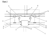
- FIG. 1 shows a tap controller housing 1 with the internals: a control unit 2, current sensors 3 and 4, switching elements 5 and 6, which by means of various electrical Lines 9 to 14 are linked.
- the tap or the feed 7 of a Consumer is connected to the lines 13, 14.
- Signal lines 8 for error message are connected to the control unit 2.
- Current sensor signal lines 9 and 10 connect the control unit 2 to adjacent tap controllers Control units left and right (not shown).
- Current sensor signal lines 11 and 12 connect the current sensors 3, 4 to adjacent tap controllers and with the left and right sides of the control unit 2.
- Figure 2 shows the interconnection of 3 Abgriffcontrollind 1.1, 1.2, 1.3 to a Power ring with the current sensor signal lines 9, 10, 11, 12 and the electric power transporting ring lines 13, 14.
- FIG. 4 shows the tap controller 1 with the electrical currents I1, I2, I3.
- the tap controller 1 is equipped with current sensors 3, 4, which make it possible to measure the current on both sides of the ring line 13, 14 according to current strength and direction. Each side of the ring line 13, 14 can be separated by means of a respective switching element 5, 6.
- the supply for a consumer connected to line 7 (not shown) or connected to line 7 feed for the loop is tapped or made between the switching elements 5 and 6.
- By interconnecting multiple tap controller creates a power ring of, for example, 3 controllers 1.1, 1.2, 1.3 ( Figure 2).
- a fault for example a short circuit on a line between controllers 1.2 and 1.3 as a loop element
- the faulty line is disconnected from the ring line by opening the corresponding switches 5.3 and 6.2 in this example.
- the error case is saved and further processed at a higher level.
- the current intensity 11, measured in sensor 3.3 is the same as the current 12 measured in sensor 4.2 (FIG. 3).
- the measured values of the current sensors 3.3 differ. and 4.2 in the current direction and / or the current.
- the detection of an overcurrent at the tap of a tap controller as a fault in a consumer connected to the line 7 (not shown) is likewise determined by means of subtraction of the current sensor values of the sensors 3 and 4 (FIG. 4).
- the current values 11 and 12 of the sensors 3 and 4 are evaluated for this purpose. Incoming or outgoing flows are subtracted from one another depending on the direction. The result is the magnitude of the incoming or outgoing current I3 at the tap.
- the current drain can be interrupted by means of the associated switches 5, 6.
Abstract
Description
Die Erfindung betrifft eine Vorrichtung zur Verbesserung für einen Powerring nach den
Merkmalen des Oberbegriffs des Patentanspruchs 1.The invention relates to a device for improving a power ring after
Features of the preamble of
Es ist bekannt, dass die Versorgung von Geräten mit elektrischer Energie maßgeblich von Einzelkomponenten als Verbraucher von elektrischer Leistung in einem Fahrzeug, insbesondere einem militärischen Fahrzeug, über einen sogenannten Powerring erfolgt, bei dem im Gegensatz zu einem sternförmigen Anschluss eines jeden Verbrauchers an einen Generator eine Ringleitung, welche die Leistungsenergie transportiert, jeden elektrischen Verbraucher mit dem Generator verbindet.It is known that the supply of equipment with electrical energy is crucial of individual components as consumers of electrical power in a vehicle, especially a military vehicle, via a so-called power ring, in contrast to a star connection of each consumer a generator a ring line, which transports the power energy, every electrical Connects consumers with the generator.
Ein Kurzschluss auf der Ringleitung des Powerrings hat zur Folge, dass alle an dem Powerring angeschlossenen Verbraucher nicht mehr versorgt werden. Üblicherweise wird dann eine Reparaturwerkstatt aufgesucht und der Fehler behoben.A short circuit on the ring circuit of the power ring has the consequence that all on the Power ring connected consumers are no longer supplied. Usually Then a repair shop will be visited and the error corrected.
In speziellen Anwendungsfällen bei militärischen Fahrzeugen kann es jedoch unerwünscht sein, dass die interne Stromversorgung durch einen einfachen Kurzschluss für alle angeschlossenen Geräte ausfällt.However, in special applications in military vehicles, it may be undesirable be that the internal power supply by a simple short circuit for all connected devices will fail.
Bekannte Ausführungen sehen zum Beispiel vor, den Powerring mittels Powerring-Controller in einzelne Segmente zu unterteilen. Die versorgten Geräte sind über Abgriffe am Powerring an den Segmenten des Powerrings angeschlossen. Bei einem Kurzschluss an einem Segment werden dann nur die Geräte, die an diesem Segment angeschlossen sind, von dem Kurzschluss beeinträchtigt und fallen aus. Die an den anderen Segmenten des Powerrings angeschlossenen Geräte werden weiterhin versorgt und bleiben weiterhin funktionsfähig. Known designs provide, for example, the power ring by means of power ring controller to divide into individual segments. The supplied devices are via taps connected to the power ring on the power ring segments. In case of a short circuit on a segment then only the devices that are connected to this segment are affected by the short circuit and fail. The other Segments of the power ring connected devices will continue to be powered and remain functional.
In der DE 199 16 452 C2 wird eine Vorrichtung für einen Powerring als Ringleitung in einem militärischen Fahrzeug für die elektrische Versorgung von Geräten, bestehend aus mehreren Controllern als Überwachungs- und Schalteinrichtungen, die entlang und an der Ringleitung angeschlossen sind, und mit weiteren Einrichtungen zur Überwachung und Steuerung der Ringleitung beschrieben, wobei sichergestellt wird mittels einer Anzahl gesteuerter Schalter, dass das Ringleitungssegment links oder rechts vom Abgriffcontroller zu- oder abgeschaltet werden kann.In DE 199 16 452 C2, a device for a power ring as a loop in a military vehicle for the electrical supply of equipment consisting from multiple controllers as monitoring and switching devices along and connected to the loop, and with other monitoring devices and control of the loop described, being ensured by means of a Number of controlled switches that the loop segment left or right of Tap controller can be switched on or off.
Nach einem Fehlerfall, zum Beispiel Kurzschluss der Ringleitung, wird der Powerring zunächst komplett abgeschaltet. Mittels sukzessivem Wiedereinschalten wird das fehlerhafte Leitungssegment identifiziert und vom Powerring abgekoppelt. Dabei kann es nachteilig sein, dass der Powerring im Fehlerfall (Kurzschluss) zunächst komplett spannungslos geschaltet werden muss, wodurch die Energieversorgung der angeschlossenen Geräte unterbrochen wird. Außerdem kann der Fehlerort bei sporadischen Fehlern erst nach einer gewissen Zeitspanne lokalisiert werden.After an error, for example, short circuit of the loop, the power ring completely switched off. By means of successive restarting the faulty Line segment identified and disconnected from the power ring. It can be disadvantageous that the power ring in the event of a fault (short circuit) initially completely de-energized must be switched, whereby the power supply of the connected Devices is interrupted. In addition, the error location for sporadic errors be localized after a certain period of time.
Aufgabe der Erfindung ist es, eine Verbesserung der Fehlererkennung in den Ringleitungselementen eines Powerrings zu realisieren.The object of the invention is to improve the error detection in the loop elements to realize a power ring.
Die Lösung dieser Aufgabe erfolgt erfindungsgemäß dadurch, dass an jedem Ringleitungselement der zu- und abfließende Strom gemessen wird. Mittels Differenzbildung der Stromwerte kann ein Fehlerfall auf dem Ringleitungselement erkannt werden, wenn der Differenzstromwert ungleich Null ist und ein Kurzschlussfall vorliegt.The solution of this task is inventively characterized in that on each ring line element the incoming and outgoing stream is measured. By difference the current values, a fault can be detected on the loop element, if the differential current value is not equal to zero and there is a short-circuit condition.
Die Vorteile der Erfindung liegen vor allem darin, dass die bisherigen Nachteile, zum Beispiel lange Zeitdauer, beim sukzessiven Wiedereinschalten des Powerrings nach einem Fehlerfall vermieden werden können. Außerdem wird auch die vom angeschlossenen Verbraucher entnommene elektrische Leistung gemessen.The advantages of the invention are, above all, that the previous disadvantages, for Example long time, when successively restarting the power ring after an error can be avoided. In addition, also from the connected Consumer taken electrical power measured.
Ein Ausführungsbeispiel der Erfindung ist in der Zeichnung schematisch dargestellt und wird im folgenden näher beschrieben. Es zeigen:
- Figur 1:
- Abgriffcontroller mit Strommessung
- Figur 2:
- Powerring mit Abgriffcontroller
- Figur 3:
- dito im Fehlerfall
- Figur 4:
- Abgriffcontroller mit Fehlerfall
- FIG. 1:
- Tap controller with current measurement
- FIG. 2:
- Powerring with tap controller
- FIG. 3:
- ditto in case of error
- FIG. 4:
- Tap controller with error
Figur 1 zeigt ein Abgriffcontrollergehäuse 1 mit den Einbauten: einer Steuerungseinheit
2, Stromsensoren 3 und 4, Schaltelementen 5 und 6, welche mittels diversen elektrischen
Leitungen 9 bis 14 verknüpft sind. Der Abgriff bzw. die Einspeisung 7 eines
Verbrauchers ist an die Leitungen 13, 14 angeschlossen. Signalleitungen 8 zur Fehlermeldung
sind an der Steuerungseinheit 2 angeschlossen. Stromsensorsignalleitungen 9
und 10 verbinden die Steuerungseinheit 2 mit benachbarten Abgriffcontrollern bzw. dazugehörenden
Steuerungseinheiten links und rechts (nicht dargestellt). Stromsensorsignalleitungen
11 und 12 verbinden die Stromsensoren 3, 4 mit benachbarten Abgriffcontrollern
und mit der linken bzw. rechten Seite der Steuerungseinheit 2.FIG. 1 shows a
Figur 2 zeigt die Zusammenschaltung von 3 Abgriffcontrollern 1.1, 1.2, 1.3 zu einem
Powerring mit den Stromsensorsignalleitungen 9, 10, 11, 12 und den elektrische Leistung
transportierenden Ringleitungen 13, 14.Figure 2 shows the interconnection of 3 Abgriffcontrollern 1.1, 1.2, 1.3 to a
Power ring with the current
In Figur 3 sind in Ergänzung zu Figur 2 die Ströme I1 und I2 auf der Ringleitung dargestellt sowie ein Kurzschlussfall auf der Leitung zwischen Anschlüssen 13.3 und 14.2.In Figure 3, in addition to Figure 2, the currents I1 and I2 are shown on the loop and a short circuit on the line between terminals 13.3 and 14.2.
In Figur 4 ist der Abgriffcontroller 1 mit den elektrischen Strömen I1, I2, I3 dargestellt.FIG. 4 shows the
Der Abgriffcontroller 1 ist mit Stromsensoren 3, 4 ausgestattet, die es ermöglichen, jeweils
den Strom auf beiden Seiten der Ringleitung 13, 14 nach Stromstärke und -richtung
zu messen. Jede Seite der Ringleitung 13, 14 kann mittels je einem Schaltelement
5, 6 abgetrennt werden. Die Versorgung für einen an Leitung 7 angeschlossenen
Verbraucher (nicht dargestellt) bzw. eine an Leitung 7 angeschlossene Einspeisung für
die Ringleitung wird zwischen den Schaltelementen 5 und 6 abgegriffen bzw. vorgenommen.
Mittels Zusammenschalten mehrerer Abgriffcontroller entsteht ein Powerring
aus zum Beispiel 3 Controllern 1.1, 1.2, 1.3 (Figur 2). Bei einem Fehler, zum Beispiel
Kurzschluss auf einer Leitung zwischen Controller 1.2 und 1.3 als Ringleitungselement,
wird die fehlerhafte Leitung durch Öffnen der entsprechenden Schalter 5.3 und 6.2 in
diesem Beispiel einpolig aus der Ringleitung herausgetrennt. Der Fehlerfall wird gespeichert
und an übergeordneter Stelle weiterverarbeitet. Im Normalfall ohne Störung ist die
Stromstärke 11, gemessen in Sensor 3.3, gleichgroß mit der Stromstärke 12, gemessen
in Sensor 4.2 (Figur 3). Bei einem Kurzschluss als Störung auf der Ringleitung zwischen
den Controllern 1.2 und 1.3 unterscheiden sich die Messwerte der Stromsensoren 3.3.
und 4.2 in der Stromrichtung und/oder der Stromstärke.
Die Erkennung eines Überstroms am Abgriff eines Abgriffcontrollers als Fehlerfall in einem
an die Leitung 7 angeschlossenen Verbraucher (nicht dargestellt) wird ebenfalls
mittels Differenzbildung der Stromsensorwerte der Sensoren 3 und 4 ermittelt (Figur 4).
In der Steuerungseinheit 2 werden dazu die Stromwerte 11 und 12 der Sensoren 3 und 4
ausgewertet. Einfließende oder abfließende Ströme werden richtungsabhängig voneinander
subtrahiert. Das Ergebnis ist die Höhe des ab- oder zufließenden Stroms I3 am
Abgriff. Bei Überschreiten eines zulässigen Stromgrenzwerts kann die Stromentnahme
mittels der zugeordneten Schalter 5,6 unterbrochen werden. The
The detection of an overcurrent at the tap of a tap controller as a fault in a consumer connected to the line 7 (not shown) is likewise determined by means of subtraction of the current sensor values of the
- 1.1.
- Abgriff-ControllergehäuseTap controller housing
- 2.Second
- Steuerungseinheitcontrol unit
- 3.Third
- Stromsensor Seite aCurrent sensor page a
- 4.4th
- Stromsensor Seite bCurrent sensor page b
- 5.5th
- Schaltelement Seite aSwitching element page a
- 6.6th
- Schaltelement Seite bSwitching element page b
- 7.7th
- Abgriff für Verbraucher bzw. Einspeisung (Plus u. Minus)Tap for consumers or feed (plus and minus)
- 8.8th.
- Signalleitungen zur Fehlersignalisierung und -quittierungSignal lines for error signaling and acknowledgment
- 9.9th
- Stromsensorsignalleitung vom benachbartem Abgriff-Controller aCurrent sensor signal line from the adjacent tap controller a
- 10.10th
- Stromsensorsignalleitung vom benachbartem Abgriff-Controller bCurrent sensor signal line from the adjacent tap controller b
- 11.11th
- Stromsensorsignalleitung vom Stromsensor Seite aCurrent sensor signal line from the current sensor page a
- 12.12th
- Stromsensorsignalleitung vom Stromsensor Seite bCurrent sensor signal line from the current sensor page b
- 13.13th
- Ringleitungsabgang Seite a (Plus u. Minus)Ring line outlet side a (plus and minus)
- 14.14th
- Ringleitungsabgang Seite b (Plus u. Minus)Ring line outlet side b (plus and minus)
Claims (7)
Applications Claiming Priority (2)
| Application Number | Priority Date | Filing Date | Title |
|---|---|---|---|
| DE2003129914 DE10329914B4 (en) | 2003-07-02 | 2003-07-02 | Error detection for Powerring |
| DE10329914 | 2003-07-02 |
Publications (3)
| Publication Number | Publication Date |
|---|---|
| EP1493630A2 true EP1493630A2 (en) | 2005-01-05 |
| EP1493630A3 EP1493630A3 (en) | 2005-11-09 |
| EP1493630B1 EP1493630B1 (en) | 2011-11-16 |
Family
ID=33426831
Family Applications (1)
| Application Number | Title | Priority Date | Filing Date |
|---|---|---|---|
| EP20040011120 Not-in-force EP1493630B1 (en) | 2003-07-02 | 2004-05-11 | Failure recognition for an electrical Powerring |
Country Status (5)
| Country | Link |
|---|---|
| US (1) | US7095134B2 (en) |
| EP (1) | EP1493630B1 (en) |
| AT (1) | ATE533670T1 (en) |
| DE (1) | DE10329914B4 (en) |
| ES (1) | ES2376548T3 (en) |
Cited By (6)
| Publication number | Priority date | Publication date | Assignee | Title |
|---|---|---|---|---|
| WO2008149235A3 (en) * | 2007-06-06 | 2009-03-12 | Ballard Claudio R | System for integrating a plurality of modules using a power/data backbone network |
| US7740501B2 (en) | 2007-06-06 | 2010-06-22 | Claudio R. Ballard | Hybrid cable for conveying data and power |
| US7856158B2 (en) | 2008-03-07 | 2010-12-21 | Ballard Claudio R | Virtual electronic switch system |
| USD638033S1 (en) | 2008-03-07 | 2011-05-17 | Ballard Claudio R | Air intake assembly |
| US9720469B2 (en) | 2011-10-04 | 2017-08-01 | Veedims, Llc | System and method for auto-discovery and mapping of networked modules |
| WO2018087260A1 (en) * | 2016-11-11 | 2018-05-17 | Leoni Bordnetz-Systeme Gmbh | Power distributor and on-board network having at least one power distributor |
Families Citing this family (25)
| Publication number | Priority date | Publication date | Assignee | Title |
|---|---|---|---|---|
| US7745425B2 (en) * | 2002-02-07 | 2010-06-29 | The Trustees Of Columbia University In The City Of New York | Non-irritating compositions containing zinc salts |
| US7879365B2 (en) * | 2002-02-07 | 2011-02-01 | The Trustees Of Columbia University In The City Of New York | Zinc salt compositions for the prevention of dermal and mucosal irritation |
| US7435429B2 (en) * | 2002-02-07 | 2008-10-14 | Trustees Of Columbia University In The City Of New York | Zinc salt compositions for the prevention of dermal and mucosal irritation |
| DE102004020830B4 (en) * | 2004-02-19 | 2010-06-10 | Lenze Automation Gmbh | Safety circuit grouping with ring concept for control units of power electronics |
| US8303337B2 (en) | 2007-06-06 | 2012-11-06 | Veedims, Llc | Hybrid cable for conveying data and power |
| US8254072B2 (en) * | 2009-11-05 | 2012-08-28 | Schneider Electric USA, Inc. | Electrical load center |
| US9598093B2 (en) * | 2010-05-18 | 2017-03-21 | Alstom Transport Technologies | Signal detection system and method |
| USD662869S1 (en) | 2010-06-01 | 2012-07-03 | Ballard Claudio R | Automotive wheel center nut |
| DE102010046152B3 (en) | 2010-09-21 | 2011-12-15 | Rheinmetall Landsysteme Gmbh | Plant with n - mechanically interconnected facilities |
| US8976541B2 (en) | 2011-08-31 | 2015-03-10 | Potens Ip Holdings Llc | Electrical power and data distribution apparatus |
| DE102012101654B3 (en) | 2012-02-29 | 2013-08-08 | Krauss-Maffei Wegmann Gmbh & Co. Kg | Military vehicle |
| DE102012207624A1 (en) * | 2012-05-08 | 2013-11-14 | Siemens Aktiengesellschaft | Module unit, network and method for monitoring a power supply network |
| US9661239B2 (en) * | 2013-04-17 | 2017-05-23 | Digital Makeup Ltd. | System and method for online processing of video images in real time |
| JP5977855B1 (en) | 2015-03-31 | 2016-08-24 | 富士重工業株式会社 | Vehicle power supply |
| DE102016115823B4 (en) | 2016-08-25 | 2023-01-05 | Auto-Kabel Management Gmbh | Motor vehicle electrical system and motor vehicle with a motor vehicle electrical system |
| JP6935437B2 (en) * | 2019-01-23 | 2021-09-15 | 矢崎総業株式会社 | Power supply |
| DE102019201582A1 (en) * | 2019-02-07 | 2020-08-13 | Zf Friedrichshafen Ag | Circuit for supplying electrical energy to a vehicle and method for supplying electrical energy to a vehicle |
| JP6909246B2 (en) * | 2019-02-19 | 2021-07-28 | 矢崎総業株式会社 | Vehicle power supply system |
| JP2021017115A (en) * | 2019-07-18 | 2021-02-15 | マツダ株式会社 | Ring-shaped power supply system |
| US11623499B2 (en) | 2019-11-08 | 2023-04-11 | Thermo King Llc | Electrical power supply management for climate-controlled system associated with automotive application |
| US11535105B2 (en) | 2019-11-08 | 2022-12-27 | Thermo King Llc | Adaptive control of transport climate control system based on available energy |
| US11539210B2 (en) | 2019-11-08 | 2022-12-27 | Thermo King Llc | Power and fault management of electrical components of a transport climate control system powered by an electric vehicle |
| US11634094B2 (en) | 2019-11-08 | 2023-04-25 | Thermo King Llc | Methods and systems for secure communication and authorization of vehicle mode change |
| US11648821B2 (en) | 2019-11-08 | 2023-05-16 | Thermo King Llc | Methods and systems of minimizing c-rate fluctuation by adjusting operation of a transport climate control system |
| JP2024043143A (en) * | 2022-09-16 | 2024-03-29 | 日立Astemo株式会社 | Onboard power supply network |
Citations (2)
| Publication number | Priority date | Publication date | Assignee | Title |
|---|---|---|---|---|
| DE19811626A1 (en) | 1997-03-17 | 1998-09-24 | Furukawa Electric Co Ltd | Current supply system for motor vehicles |
| DE19916452C2 (en) | 1999-04-12 | 2001-10-25 | Rheinmetall Landsysteme Gmbh | Device for a power ring |
Family Cites Families (11)
| Publication number | Priority date | Publication date | Assignee | Title |
|---|---|---|---|---|
| US3249709A (en) * | 1962-04-16 | 1966-05-03 | Symington Wayne Corp | Shaft rotation signalling switch device |
| US3249703A (en) * | 1963-02-25 | 1966-05-03 | Bell Telephone Labor Inc | Switching converter power supplies with series-connected inputs |
| GB1068719A (en) * | 1965-04-20 | 1967-05-10 | English Electric Co Ltd | Direct current power systems |
| US4051383A (en) * | 1976-03-30 | 1977-09-27 | Amp Incorporated | Electrical harnesses and connecting devices therefor |
| JPH08298480A (en) * | 1995-04-27 | 1996-11-12 | Honda Motor Co Ltd | Wiring structure for multiplex communication system for automobile |
| US5604385A (en) * | 1995-05-22 | 1997-02-18 | Target Hi-Tech Electronics Ltd. | Apparatus for and method of evenly distributing an electrical load across a three phase power distribution network |
| US6567522B1 (en) * | 1999-04-20 | 2003-05-20 | Godigital Telecommunications, Inc. | Voltage alternating switch circuit |
| GB9921373D0 (en) * | 1999-09-10 | 1999-11-10 | Alpha Thames Limited | Modular sea-bed system |
| US20040051383A1 (en) * | 2002-09-12 | 2004-03-18 | Clark Charles Albert | Switching mode current limiting power controller circuit |
| US7432614B2 (en) * | 2003-01-17 | 2008-10-07 | Hong Kong University Of Science And Technology | Single-inductor multiple-output switching converters in PCCM with freewheel switching |
| US7199487B2 (en) * | 2003-03-21 | 2007-04-03 | Fci Americas Technology, Inc. | Modular wiring harnesses |
-
2003
- 2003-07-02 DE DE2003129914 patent/DE10329914B4/en not_active Expired - Fee Related
-
2004
- 2004-05-11 AT AT04011120T patent/ATE533670T1/en active
- 2004-05-11 EP EP20040011120 patent/EP1493630B1/en not_active Not-in-force
- 2004-05-11 ES ES04011120T patent/ES2376548T3/en active Active
- 2004-07-01 US US10/880,462 patent/US7095134B2/en not_active Expired - Fee Related
Patent Citations (2)
| Publication number | Priority date | Publication date | Assignee | Title |
|---|---|---|---|---|
| DE19811626A1 (en) | 1997-03-17 | 1998-09-24 | Furukawa Electric Co Ltd | Current supply system for motor vehicles |
| DE19916452C2 (en) | 1999-04-12 | 2001-10-25 | Rheinmetall Landsysteme Gmbh | Device for a power ring |
Cited By (10)
| Publication number | Priority date | Publication date | Assignee | Title |
|---|---|---|---|---|
| WO2008149235A3 (en) * | 2007-06-06 | 2009-03-12 | Ballard Claudio R | System for integrating a plurality of modules using a power/data backbone network |
| US7740501B2 (en) | 2007-06-06 | 2010-06-22 | Claudio R. Ballard | Hybrid cable for conveying data and power |
| US7940673B2 (en) | 2007-06-06 | 2011-05-10 | Veedims, Llc | System for integrating a plurality of modules using a power/data backbone network |
| US7856158B2 (en) | 2008-03-07 | 2010-12-21 | Ballard Claudio R | Virtual electronic switch system |
| USD638033S1 (en) | 2008-03-07 | 2011-05-17 | Ballard Claudio R | Air intake assembly |
| US9720469B2 (en) | 2011-10-04 | 2017-08-01 | Veedims, Llc | System and method for auto-discovery and mapping of networked modules |
| WO2018087260A1 (en) * | 2016-11-11 | 2018-05-17 | Leoni Bordnetz-Systeme Gmbh | Power distributor and on-board network having at least one power distributor |
| CN110024248A (en) * | 2016-11-11 | 2019-07-16 | 莱尼电气系统有限公司 | Power divider and onboard power system at least one power divider |
| US10676052B2 (en) | 2016-11-11 | 2020-06-09 | Leoni Bordnetz-Systeme Gmbh | Power distributor, and on-board electrical system having at least one power distributor |
| CN110024248B (en) * | 2016-11-11 | 2021-11-02 | 莱尼电气系统有限公司 | Power splitter and on-board electrical system having at least one power splitter |
Also Published As
| Publication number | Publication date |
|---|---|
| ES2376548T3 (en) | 2012-03-14 |
| EP1493630A3 (en) | 2005-11-09 |
| US20050001431A1 (en) | 2005-01-06 |
| EP1493630B1 (en) | 2011-11-16 |
| ATE533670T1 (en) | 2011-12-15 |
| DE10329914B4 (en) | 2005-09-01 |
| DE10329914A1 (en) | 2005-02-03 |
| US7095134B2 (en) | 2006-08-22 |
Similar Documents
| Publication | Publication Date | Title |
|---|---|---|
| DE10329914B4 (en) | Error detection for Powerring | |
| DE102005055325C5 (en) | Safety switching device for fail-safe disconnection of an electrical consumer | |
| DE102012207624A1 (en) | Module unit, network and method for monitoring a power supply network | |
| DE112017005122T5 (en) | Vehicle-side control | |
| EP2498270B1 (en) | Security relay and security-oriented communication system | |
| DE112017004066T5 (en) | BATTERY CONTROLLER | |
| DE102018119916A1 (en) | Electrical AC / DC conversion arrangement | |
| WO2014187634A2 (en) | Protection circuit for an actuator, actuator device and method for operating an electric actuator | |
| DE102015000576B4 (en) | Motor vehicle with switching device for an on-board power supply-operated component | |
| DE19837796A1 (en) | Procedure for determining the pump condition | |
| EP3266031A1 (en) | Switch device for operating at least one load | |
| EP0609261B1 (en) | Device for testing an electrical drive unit | |
| WO2002071600A2 (en) | Safety switch device | |
| EP1308803B1 (en) | Power supply diagnostic system | |
| EP0503170B1 (en) | Bus-oriented multiplex system | |
| DE19844185C2 (en) | bus line | |
| EP3531137A1 (en) | Energy supply device and method for operating same | |
| DE102010033047A1 (en) | Method for detecting fault in onboard network of motor car, involves measuring voltage and current level of components in onboard network and computing delivered and consumed power of each component to detect fault in network | |
| DE19808595B4 (en) | Arrangement with an electrical load in series with two controllable semiconductor devices | |
| DE102023200456A1 (en) | Method for monitoring an energy supply of a motor vehicle | |
| EP0269952A2 (en) | Fault-tolerant ring power supply system | |
| WO2023148097A1 (en) | Power distributor, power distribution system and vehicle therewith | |
| DE102020207189A1 (en) | SAFETY SWITCH UNIT AND SAFETY PROCEDURES FOR AN ELECTRIC VEHICLE | |
| DE102020115701A1 (en) | Three-phase reversing stage and switching device for switching a three-phase motor | |
| EP1450459A1 (en) | Fault tolerant busbarstation with circuit-breakers and method for controlling a such station |
Legal Events
| Date | Code | Title | Description |
|---|---|---|---|
| PUAI | Public reference made under article 153(3) epc to a published international application that has entered the european phase |
Free format text: ORIGINAL CODE: 0009012 |
|
| AK | Designated contracting states |
Kind code of ref document: A2 Designated state(s): AT BE BG CH CY CZ DE DK EE ES FI FR GB GR HU IE IT LI LU MC NL PL PT RO SE SI SK TR |
|
| AX | Request for extension of the european patent |
Extension state: AL HR LT LV MK |
|
| PUAL | Search report despatched |
Free format text: ORIGINAL CODE: 0009013 |
|
| AK | Designated contracting states |
Kind code of ref document: A3 Designated state(s): AT BE BG CH CY CZ DE DK EE ES FI FR GB GR HU IE IT LI LU MC NL PL PT RO SE SI SK TR |
|
| AX | Request for extension of the european patent |
Extension state: AL HR LT LV MK |
|
| RAP1 | Party data changed (applicant data changed or rights of an application transferred) |
Owner name: RHEINMETALL LANDSYSTEME GMBH |
|
| RIC1 | Information provided on ipc code assigned before grant |
Ipc: 7B 60R 16/02 A Ipc: 7H 02H 7/28 B Ipc: 7H 02J 1/00 B |
|
| 17P | Request for examination filed |
Effective date: 20051011 |
|
| AKX | Designation fees paid |
Designated state(s): AT BE BG CH CY CZ DE DK EE ES FI FR GB GR HU IE IT LI LU MC NL PL PT RO SE SI SK TR |
|
| 17Q | First examination report despatched |
Effective date: 20090918 |
|
| GRAP | Despatch of communication of intention to grant a patent |
Free format text: ORIGINAL CODE: EPIDOSNIGR1 |
|
| GRAS | Grant fee paid |
Free format text: ORIGINAL CODE: EPIDOSNIGR3 |
|
| GRAA | (expected) grant |
Free format text: ORIGINAL CODE: 0009210 |
|
| AK | Designated contracting states |
Kind code of ref document: B1 Designated state(s): AT BE BG CH CY CZ DE DK EE ES FI FR GB GR HU IE IT LI LU MC NL PL PT RO SE SI SK TR |
|
| REG | Reference to a national code |
Ref country code: GB Ref legal event code: FG4D Free format text: NOT ENGLISH |
|
| REG | Reference to a national code |
Ref country code: CH Ref legal event code: EP |
|
| REG | Reference to a national code |
Ref country code: IE Ref legal event code: FG4D Free format text: LANGUAGE OF EP DOCUMENT: GERMAN |
|
| REG | Reference to a national code |
Ref country code: DE Ref legal event code: R096 Ref document number: 502004013057 Country of ref document: DE Effective date: 20120112 |
|
| REG | Reference to a national code |
Ref country code: CH Ref legal event code: NV Representative=s name: KELLER & PARTNER PATENTANWAELTE AG |
|
| REG | Reference to a national code |
Ref country code: SE Ref legal event code: TRGR |
|
| REG | Reference to a national code |
Ref country code: NL Ref legal event code: T3 |
|
| REG | Reference to a national code |
Ref country code: ES Ref legal event code: FG2A Ref document number: 2376548 Country of ref document: ES Kind code of ref document: T3 Effective date: 20120314 |
|
| PG25 | Lapsed in a contracting state [announced via postgrant information from national office to epo] |
Ref country code: GR Free format text: LAPSE BECAUSE OF FAILURE TO SUBMIT A TRANSLATION OF THE DESCRIPTION OR TO PAY THE FEE WITHIN THE PRESCRIBED TIME-LIMIT Effective date: 20120217 Ref country code: SI Free format text: LAPSE BECAUSE OF FAILURE TO SUBMIT A TRANSLATION OF THE DESCRIPTION OR TO PAY THE FEE WITHIN THE PRESCRIBED TIME-LIMIT Effective date: 20111116 Ref country code: PT Free format text: LAPSE BECAUSE OF FAILURE TO SUBMIT A TRANSLATION OF THE DESCRIPTION OR TO PAY THE FEE WITHIN THE PRESCRIBED TIME-LIMIT Effective date: 20120316 Ref country code: PL Free format text: LAPSE BECAUSE OF FAILURE TO SUBMIT A TRANSLATION OF THE DESCRIPTION OR TO PAY THE FEE WITHIN THE PRESCRIBED TIME-LIMIT Effective date: 20111116 |
|
| REG | Reference to a national code |
Ref country code: IE Ref legal event code: FD4D |
|
| PG25 | Lapsed in a contracting state [announced via postgrant information from national office to epo] |
Ref country code: CY Free format text: LAPSE BECAUSE OF FAILURE TO SUBMIT A TRANSLATION OF THE DESCRIPTION OR TO PAY THE FEE WITHIN THE PRESCRIBED TIME-LIMIT Effective date: 20111116 |
|
| PG25 | Lapsed in a contracting state [announced via postgrant information from national office to epo] |
Ref country code: DK Free format text: LAPSE BECAUSE OF FAILURE TO SUBMIT A TRANSLATION OF THE DESCRIPTION OR TO PAY THE FEE WITHIN THE PRESCRIBED TIME-LIMIT Effective date: 20111116 Ref country code: IE Free format text: LAPSE BECAUSE OF FAILURE TO SUBMIT A TRANSLATION OF THE DESCRIPTION OR TO PAY THE FEE WITHIN THE PRESCRIBED TIME-LIMIT Effective date: 20111116 Ref country code: CZ Free format text: LAPSE BECAUSE OF FAILURE TO SUBMIT A TRANSLATION OF THE DESCRIPTION OR TO PAY THE FEE WITHIN THE PRESCRIBED TIME-LIMIT Effective date: 20111116 Ref country code: EE Free format text: LAPSE BECAUSE OF FAILURE TO SUBMIT A TRANSLATION OF THE DESCRIPTION OR TO PAY THE FEE WITHIN THE PRESCRIBED TIME-LIMIT Effective date: 20111116 Ref country code: SK Free format text: LAPSE BECAUSE OF FAILURE TO SUBMIT A TRANSLATION OF THE DESCRIPTION OR TO PAY THE FEE WITHIN THE PRESCRIBED TIME-LIMIT Effective date: 20111116 Ref country code: BG Free format text: LAPSE BECAUSE OF FAILURE TO SUBMIT A TRANSLATION OF THE DESCRIPTION OR TO PAY THE FEE WITHIN THE PRESCRIBED TIME-LIMIT Effective date: 20120216 |
|
| PG25 | Lapsed in a contracting state [announced via postgrant information from national office to epo] |
Ref country code: RO Free format text: LAPSE BECAUSE OF FAILURE TO SUBMIT A TRANSLATION OF THE DESCRIPTION OR TO PAY THE FEE WITHIN THE PRESCRIBED TIME-LIMIT Effective date: 20111116 |
|
| PLBE | No opposition filed within time limit |
Free format text: ORIGINAL CODE: 0009261 |
|
| STAA | Information on the status of an ep patent application or granted ep patent |
Free format text: STATUS: NO OPPOSITION FILED WITHIN TIME LIMIT |
|
| 26N | No opposition filed |
Effective date: 20120817 |
|
| BERE | Be: lapsed |
Owner name: RHEINMETALL LANDSYSTEME G.M.B.H. Effective date: 20120531 |
|
| REG | Reference to a national code |
Ref country code: DE Ref legal event code: R097 Ref document number: 502004013057 Country of ref document: DE Effective date: 20120817 |
|
| PG25 | Lapsed in a contracting state [announced via postgrant information from national office to epo] |
Ref country code: MC Free format text: LAPSE BECAUSE OF NON-PAYMENT OF DUE FEES Effective date: 20120531 |
|
| PG25 | Lapsed in a contracting state [announced via postgrant information from national office to epo] |
Ref country code: BE Free format text: LAPSE BECAUSE OF NON-PAYMENT OF DUE FEES Effective date: 20120531 |
|
| PG25 | Lapsed in a contracting state [announced via postgrant information from national office to epo] |
Ref country code: FI Free format text: LAPSE BECAUSE OF FAILURE TO SUBMIT A TRANSLATION OF THE DESCRIPTION OR TO PAY THE FEE WITHIN THE PRESCRIBED TIME-LIMIT Effective date: 20111116 |
|
| PG25 | Lapsed in a contracting state [announced via postgrant information from national office to epo] |
Ref country code: TR Free format text: LAPSE BECAUSE OF FAILURE TO SUBMIT A TRANSLATION OF THE DESCRIPTION OR TO PAY THE FEE WITHIN THE PRESCRIBED TIME-LIMIT Effective date: 20111116 |
|
| PG25 | Lapsed in a contracting state [announced via postgrant information from national office to epo] |
Ref country code: LU Free format text: LAPSE BECAUSE OF NON-PAYMENT OF DUE FEES Effective date: 20120511 |
|
| PG25 | Lapsed in a contracting state [announced via postgrant information from national office to epo] |
Ref country code: HU Free format text: LAPSE BECAUSE OF FAILURE TO SUBMIT A TRANSLATION OF THE DESCRIPTION OR TO PAY THE FEE WITHIN THE PRESCRIBED TIME-LIMIT Effective date: 20040511 |
|
| REG | Reference to a national code |
Ref country code: CH Ref legal event code: PCAR Free format text: NEW ADDRESS: EIGERSTRASSE 2 POSTFACH, 3000 BERN 14 (CH) |
|
| REG | Reference to a national code |
Ref country code: FR Ref legal event code: PLFP Year of fee payment: 13 |
|
| PGFP | Annual fee paid to national office [announced via postgrant information from national office to epo] |
Ref country code: NL Payment date: 20160519 Year of fee payment: 13 |
|
| PGFP | Annual fee paid to national office [announced via postgrant information from national office to epo] |
Ref country code: CH Payment date: 20160519 Year of fee payment: 13 Ref country code: GB Payment date: 20160520 Year of fee payment: 13 Ref country code: ES Payment date: 20160512 Year of fee payment: 13 Ref country code: DE Payment date: 20160520 Year of fee payment: 13 |
|
| PGFP | Annual fee paid to national office [announced via postgrant information from national office to epo] |
Ref country code: AT Payment date: 20160520 Year of fee payment: 13 Ref country code: FR Payment date: 20160520 Year of fee payment: 13 Ref country code: IT Payment date: 20160524 Year of fee payment: 13 Ref country code: SE Payment date: 20160519 Year of fee payment: 13 |
|
| REG | Reference to a national code |
Ref country code: DE Ref legal event code: R119 Ref document number: 502004013057 Country of ref document: DE |
|
| REG | Reference to a national code |
Ref country code: CH Ref legal event code: PL |
|
| REG | Reference to a national code |
Ref country code: SE Ref legal event code: EUG |
|
| REG | Reference to a national code |
Ref country code: NL Ref legal event code: MM Effective date: 20170601 |
|
| REG | Reference to a national code |
Ref country code: AT Ref legal event code: MM01 Ref document number: 533670 Country of ref document: AT Kind code of ref document: T Effective date: 20170511 |
|
| GBPC | Gb: european patent ceased through non-payment of renewal fee |
Effective date: 20170511 |
|
| PG25 | Lapsed in a contracting state [announced via postgrant information from national office to epo] |
Ref country code: AT Free format text: LAPSE BECAUSE OF NON-PAYMENT OF DUE FEES Effective date: 20170511 |
|
| PG25 | Lapsed in a contracting state [announced via postgrant information from national office to epo] |
Ref country code: CH Free format text: LAPSE BECAUSE OF NON-PAYMENT OF DUE FEES Effective date: 20170531 Ref country code: LI Free format text: LAPSE BECAUSE OF NON-PAYMENT OF DUE FEES Effective date: 20170531 Ref country code: SE Free format text: LAPSE BECAUSE OF NON-PAYMENT OF DUE FEES Effective date: 20170512 |
|
| REG | Reference to a national code |
Ref country code: FR Ref legal event code: ST Effective date: 20180131 |
|
| PG25 | Lapsed in a contracting state [announced via postgrant information from national office to epo] |
Ref country code: NL Free format text: LAPSE BECAUSE OF NON-PAYMENT OF DUE FEES Effective date: 20170601 |
|
| PG25 | Lapsed in a contracting state [announced via postgrant information from national office to epo] |
Ref country code: GB Free format text: LAPSE BECAUSE OF NON-PAYMENT OF DUE FEES Effective date: 20170511 Ref country code: DE Free format text: LAPSE BECAUSE OF NON-PAYMENT OF DUE FEES Effective date: 20171201 |
|
| PG25 | Lapsed in a contracting state [announced via postgrant information from national office to epo] |
Ref country code: FR Free format text: LAPSE BECAUSE OF NON-PAYMENT OF DUE FEES Effective date: 20170531 Ref country code: IT Free format text: LAPSE BECAUSE OF NON-PAYMENT OF DUE FEES Effective date: 20170511 |
|
| REG | Reference to a national code |
Ref country code: ES Ref legal event code: FD2A Effective date: 20180626 |
|
| PG25 | Lapsed in a contracting state [announced via postgrant information from national office to epo] |
Ref country code: ES Free format text: LAPSE BECAUSE OF NON-PAYMENT OF DUE FEES Effective date: 20170512 |