EP1493886A1 - Structure modulable pliable pour tente ou analogue a montage rapide - Google Patents
Structure modulable pliable pour tente ou analogue a montage rapide Download PDFInfo
- Publication number
- EP1493886A1 EP1493886A1 EP03360079A EP03360079A EP1493886A1 EP 1493886 A1 EP1493886 A1 EP 1493886A1 EP 03360079 A EP03360079 A EP 03360079A EP 03360079 A EP03360079 A EP 03360079A EP 1493886 A1 EP1493886 A1 EP 1493886A1
- Authority
- EP
- European Patent Office
- Prior art keywords
- ridge
- arches
- profiles
- piece
- arch
- Prior art date
- Legal status (The legal status is an assumption and is not a legal conclusion. Google has not performed a legal analysis and makes no representation as to the accuracy of the status listed.)
- Granted
Links
- 238000006073 displacement reaction Methods 0.000 claims description 3
- 230000002441 reversible effect Effects 0.000 claims description 3
- 238000007373 indentation Methods 0.000 claims description 2
- 239000004744 fabric Substances 0.000 claims 1
- 230000015556 catabolic process Effects 0.000 description 5
- 101150097977 arch-1 gene Proteins 0.000 description 2
- 230000000903 blocking effect Effects 0.000 description 1
- 230000000694 effects Effects 0.000 description 1
- 238000004806 packaging method and process Methods 0.000 description 1
- 238000000926 separation method Methods 0.000 description 1
- 238000004904 shortening Methods 0.000 description 1
Images

Classifications
-
- E—FIXED CONSTRUCTIONS
- E04—BUILDING
- E04H—BUILDINGS OR LIKE STRUCTURES FOR PARTICULAR PURPOSES; SWIMMING OR SPLASH BATHS OR POOLS; MASTS; FENCING; TENTS OR CANOPIES, IN GENERAL
- E04H15/00—Tents or canopies, in general
- E04H15/32—Parts, components, construction details, accessories, interior equipment, specially adapted for tents, e.g. guy-line equipment, skirts, thresholds
- E04H15/34—Supporting means, e.g. frames
- E04H15/44—Supporting means, e.g. frames collapsible, e.g. breakdown type
- E04H15/48—Supporting means, e.g. frames collapsible, e.g. breakdown type foldable, i.e. having pivoted or hinged means
Definitions
- the present invention relates to a modular structure foldable tent or similar quick-mount.
- the invention particularly relates to tents adapted to emergency situations, and for military use, that is to say, relatively low volume disassembled, which can be mounted and deployed quickly while providing shelter from a large resistance to weather conditions.
- a tent comprises a supporting structure a canvas, said structure being removable, and constituted this effect of the assembly by interlocking of profiles of type tubular.
- the present invention aims to propose a structure modular folding tent or similar quick-mount, to remedy the various disadvantages mentioned above, all by being of simple design.
- Foldable modular structure for tent or the like mounting is of the type consisting of the assembly of tubular type sections, and intended to support a canvas, said profiles making it possible in particular to form at least two arches vis-à-vis connected by at least two failures of which a fa ⁇ tière, and it is essentially characterized in that said faults are made of the abutment of two profiles each secured by their other end to a room fa ⁇ tière that includes each of said arches, said end comprising on the one hand pivoting means allowing it to pivot on said ridge piece along a perpendicular axis on the plane of the arch, while indexing means limit angularly said pivoting; and on the other hand means of pivoting allowing the articulation of said end according to a transverse axis, parallel to the plane of the arch to allow the folding of said section parallel to said arch, while the abutment of the two sections of the failure fa ⁇ tière is realized through means of nesting able to ensure the immobilization in
- connection of the tailboard faults to an arch is performed through a joint comprising a part intermediate bearing two pivots perpendicular axes one relative to each other, one ensuring the connection with the room perpendicular to the plane of said arch, while the other provides the link with said faults.
- control of the angular orientation of each of the profiles of the faults is realized by through a recessed impression in the room and with which the intermediate piece cooperates, the forms of said intermediate piece and said imprint being chosen to limit angularly the displacement of one with respect to the other.
- the fault or failures which connect two arches, other than the faults consist of two sections articulated pivotally on the one hand to one another and other part to their respective arches so as to allow the folding from one to the other and thus the bringing together of two arches neighbors.
- the joint connecting the two sections constituting a breakdown comprises reversible blocking means to maintain said two profiles aligned after deployment.
- each of the arches consists of a piece fa ⁇ tière and two chevrons, which are articulated on said faience piece along distinct axes perpendicular to the plan of the ark.
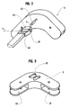
- Figures 1a, 1b and 1c represent the roof portion of a foldable modular structure according to the invention. As it happens it is a two-slope roof, knowing that it is possible, well of infrequent utility, to build a single roof slope, having the features according to the invention.
- the structure modular includes two arches 1 and 2, each V-shaped overturned and consist of a piece of ridge 3, represented more in detail in Figure 3, on which are articulated two sections, or rafters, for each arch 1 and 2, respectively 10 and 11, and 20 and 21.
- the two arches 1 and 2 are connected by three breakdowns, a breakdown cleft 4 which extends between the two ridge parts 3, and two faults 5 and 6 which connect the ends, other than those distinct axes parallel to the X axis, so that they can be place parallel to each other.
- joints 52 and 62 comprise means to block them, reversibly, the profiles, 50 and 51, and 60 and 61, when deployed, i.e. aligned.
- the locking means used may for example consist of indexing means ball.
- the articulations 42 also comprise a system of locking. Locking is carried out by the cooperation of secured to the ridge parts 3, profiles, respectively 10 and 21, and 11 and 20.
- the tip 5 is composed of two sections 50 and 51 articulated one to the other via a hinge 52, while the profile 50 is connected to the profile 10 through a 53 and that the section 51 is connected to the section 21 54.
- the pivot axes of the joints 52, 53 and 54 are parallel, and perpendicular in the plane defined by sections 10 and 21 and outages 4 and 5.
- the tip 6 is composed of sections 60 and 61 connected by means of a hinge 62, the profile 60 being connected to the profile 20 via a articulation 63, and the profile 61 to the profile 11 through a articulation 64, while the joints 62, 63 and 64 are parallel, and perpendicular to the plane defined by the profiles 11 and 20 and the breakdowns 4 and 6.
- the edge fault 4 consists of two sections 40 and 41, butted together by interlocking with one another, with rotation. Profiles 40 and 41 are joined to their room respective ridge 3 through a hinge 42 comprising two pivot axes.
- an articulation 42 comprises on the one hand a pivot 43 of axis X perpendicular to the plane of the arch 1, 2, and which allows the connection of the faults 4 to the ridge piece 3 through an intermediate piece 44, itself pivotally mounted on a pivot 45 of transverse Y axis, perpendicular to the axis X of the pivot 43, and held in a yoke 46 integral with the profile 40 or 41.
- sections 10 and 11, respectively 20 and 21, are articulated on the ridge part 3 in screeds respectively 30 and 31, visible in Figure 3, according to means for interlocking the profiles 40 and 41 one inside the other, and means for controlling the pivoting along the X axis.
- the control means consist of indexing means of the angular position of each of the profiles 40 and 41 with respect to its respective ridge part 3.
- a ridge piece 3 which comprises at the level of the region of joining the profile 40 or 41, via the pivot 43, a hollow recess 33 for receiving the end of the intermediate piece 44, and whose shape defines the limits displacement of Exhibit 44.
- this footprint 33 is intended to allow only one 90 ° pivoting of the piece 44 and thus of the profiles 40 and 41.
- the recessed impression 33 can be replaced by protruding elements having the same function, that is to say that wisely arranged elements constitute stops at the piece 44 and angularly limit the pivoting thereof, the indentation, however, being preferred for reasons congestion.
- the impression 33 defines two extreme angular positions of the pivot 43 and therefore two different extreme orientations of the pivot 45, in this case the horizontal one allowing the folding of the profile 40 or 41 between the profiles 10 11, and 20 and 21, the other vertical not allowing said folding.
- the two pieces 3 being identical, the fingerprints 33 are opposite each other so that the direction of pivoting of the profile 40 to move the pivot 45 of an orientation horizontally in a vertical orientation, is the opposite of that of the section 41 to perform the same operation.
- the interlocking imprints are of section rectangular cross section.
- the ridge parts 3 are provided adapted to receive an edge failure 4 on each side, so to allow the joining of one arch to two others.
- arches 1 and 2 may comprise other sections, not shown, each integral with one of the profiles 10, 11, 20 and 21, near the articulation respectively 53, 64, 63 and 54, which constitute the feet of the structure.
Abstract
Description
- les figures 1a, 1b et 1c représentent des vues schématiques partielles en perspective d'une structure modulaire pliable selon l'invention, dans des positions différentes de déploiement.
- la figure 2 représente une vue schématique en perspective et en éclaté d'une partie de la même structure.
- la figure 3 représente une vue en perspective d'un élément de la même structure.
Claims (7)
- Structure modulaire pliable pour tente ou analogue à montage rapide, du type constitué de l'assemblage de profilés de type tubulaire, et destinée à supporter une toile, lesdits profilés permettant notamment de former au moins deux arches (1, 2) en vis-à-vis reliées par au moins deux pannes (4, 5, 6) dont une faítière (4), caractérisée en ce que ladite panne faítière (4) est constituée de l'aboutement de deux profilés (40, 41), solidarisés chacun par leur autre extrémité à une pièce faítière (3) que comporte chacune desdites arches (1, 2), ladite extrémité comportant d'une part des moyens de pivotement (43) lui permettant de pivoter sur ladite pièce faítière (3) selon un axe (X) perpendiculaire au plan de l'arche (1, 2), alors que des moyens d'indexage (44, 33) limitent angulairement ledit pivotement ; et d'autre part des moyens de pivotement (45) permettant l'articulation de ladite extrémité selon un axe transversal (Y), parallèle au plan de l'arche (1, 2) afin de permettre le repliement dudit profilé (40, 41) parallèlement à ladite arche (1, 2), tandis que l'aboutement des deux profilés (40, 41) de la panne faítière (4) est réalisé par l'intermédiaire de moyens d'emboítement aptes à assurer l'immobilisation en pivotement axial d'un profilé ( 40, 41) par rapport à l'autre selon des positions angulaires de ceux-ci définies par lesdits moyens d'indexage (44, 33).
- Structure selon la revendication 1, caractérisée en ce que la liaison de la panne faítière (4) à une arche (1, 2) est réalisée au travers d'une articulation (42) comprenant une pièce intermédiaire (44) portant deux pivots (43, 45) d'axes (X, Y) perpendiculaires l'un par rapport à l'autre, l'un assurant la liaison avec la pièce faítière (3) perpendiculairement au plan de ladite arche (1, 2), tandis que l'autre assure la liaison avec ladite panne faítière (4).
- Structure selon la revendication 2, caractérisée en ce que le contrôle de l'orientation angulaire de chacun des profilés (40, 41) de la panne faítière (4) est réalisé par l'intermédiaire d'une empreinte en creux (33) pratiquée dans la pièce faítière (3) et avec laquelle coopère la pièce intermédiaire (44), les formes de ladite pièce intermédiaire (44) et de ladite empreinte (33) étant choisies pour limiter angulairement le déplacement de l'une par rapport à l'autre.
- Dispositif selon la revendication 2, caractérisé en ce que le contrôle de l'orientation angulaire de chacun des profilés (40, 41) de la panne faítière (4) est réalisé par l'intermédiaire d'éléments faisant saillie de la pièce faítière (3) et avec lesquels coopère la pièce intermédiaire (44), les emplacements de ces éléments permettant de limiter angulairement le déplacement en pivotement.
- Structure selon l'une quelconque des revendications précédentes, caractérisé en ce que la ou les pannes (5, 6) qui relient deux arches (1, 2), autres que la panne faítière (4), sont constituées de deux profilés (50, 51, 60, 61) articulés en pivotement d'une part l'un à l'autre, et d'autre part à leur arche respective (1, 2) en sorte de permettre le repliement de l'un sur l'autre et donc le rapprochement de deux arches voisines (1, 2).
- Structure selon la revendication 5, caractérisée en ce que l'articulation (52, 62) reliant les deux profilés (50, 51, 60, 61) constituant une panne (5, 6), comporte des moyens de blocage réversible permettant de maintenir lesdits deux profilés (50, 51, 60, 61) alignés, après déploiement.
- Structure selon l'une quelconque des revendications précédentes, caractérisée en ce que chacune des arches (1, 2) est constituée d'une pièce faítière (3) et de deux chevrons (10, 11, 20, 21), lesquels sont articulés sur ladite pièce faítière (3) selon des axes distincts et perpendiculaires au plan de l'arche (1, 2).
Priority Applications (6)
| Application Number | Priority Date | Filing Date | Title |
|---|---|---|---|
| AT03360079T ATE318975T1 (de) | 2003-07-01 | 2003-07-01 | Schnell aufbaubare, modulare und faltbare struktur für zelte oder dergleichen |
| ES03360079T ES2258705T3 (es) | 2003-07-01 | 2003-07-01 | Estructura modular plegable para tienda o similar de montaje rapido. |
| DE60303776T DE60303776T2 (de) | 2003-07-01 | 2003-07-01 | Schnell aufbaubare, modulare und faltbare Struktur für Zelte oder dergleichen |
| EP03360079A EP1493886B1 (fr) | 2003-07-01 | 2003-07-01 | Structure modulable pliable pour tente ou analogue a montage rapide |
| US10/880,420 US7290553B2 (en) | 2003-07-01 | 2004-06-29 | Folding modular structure for a tent or similar for fast mounting |
| CNB2004100622241A CN1271298C (zh) | 2003-07-01 | 2004-06-30 | 快速组装帐篷的折叠结构组件 |
Applications Claiming Priority (1)
| Application Number | Priority Date | Filing Date | Title |
|---|---|---|---|
| EP03360079A EP1493886B1 (fr) | 2003-07-01 | 2003-07-01 | Structure modulable pliable pour tente ou analogue a montage rapide |
Publications (2)
| Publication Number | Publication Date |
|---|---|
| EP1493886A1 true EP1493886A1 (fr) | 2005-01-05 |
| EP1493886B1 EP1493886B1 (fr) | 2006-03-01 |
Family
ID=33427271
Family Applications (1)
| Application Number | Title | Priority Date | Filing Date |
|---|---|---|---|
| EP03360079A Expired - Lifetime EP1493886B1 (fr) | 2003-07-01 | 2003-07-01 | Structure modulable pliable pour tente ou analogue a montage rapide |
Country Status (6)
| Country | Link |
|---|---|
| US (1) | US7290553B2 (fr) |
| EP (1) | EP1493886B1 (fr) |
| CN (1) | CN1271298C (fr) |
| AT (1) | ATE318975T1 (fr) |
| DE (1) | DE60303776T2 (fr) |
| ES (1) | ES2258705T3 (fr) |
Cited By (5)
| Publication number | Priority date | Publication date | Assignee | Title |
|---|---|---|---|---|
| EP1914364A2 (fr) | 2006-10-19 | 2008-04-23 | Tolpin S. A. | Structure pliable pour le montage d'une tente |
| DE202013100693U1 (de) | 2012-02-16 | 2013-06-05 | Zet Yapi Ürünleri Insaat Ve Ticaret Anonim Sirketi | Zeltgestängemechanismus mit einer einfachen Konstruktion |
| FR3013374A1 (fr) * | 2013-11-21 | 2015-05-22 | Becher Stp | Structure modulaire pliable pour tente ou abris similaire a montage rapide |
| WO2018150058A1 (fr) | 2017-02-20 | 2018-08-23 | Utilis | Element de connexion pour structure porteuse d'abri de type tente, et structure et abri correspondants |
| WO2018150059A1 (fr) | 2017-02-20 | 2018-08-23 | Utilis | Piece thermoplastique renforcee pour une structure porteuse |
Families Citing this family (17)
| Publication number | Priority date | Publication date | Assignee | Title |
|---|---|---|---|---|
| US20090167051A1 (en) * | 2007-11-12 | 2009-07-02 | Bernardo Alfredo P | Collapsible Sun Cover for Motor Vehicle Interior |
| US7975712B2 (en) * | 2007-12-28 | 2011-07-12 | Beacco Michael A | Hunting blind |
| US8186369B2 (en) | 2008-05-14 | 2012-05-29 | Swimways Corporation | Collapsible shelter |
| US7931037B1 (en) * | 2009-02-25 | 2011-04-26 | Ryan Jason S | Covering system |
| US8056573B2 (en) * | 2009-03-11 | 2011-11-15 | Foldable Stuff, Llc | Freestanding collapsible shelter |
| US7987864B1 (en) | 2009-05-29 | 2011-08-02 | Harrison Joshua Jackson | Deployable structures and methods for assembling same |
| US8978680B2 (en) | 2012-05-04 | 2015-03-17 | KD Kanopy Inc. | Removably mountable roof frame for use with an expandable canopy |
| US9097034B2 (en) * | 2012-05-24 | 2015-08-04 | California Industrial Facilities Resources, Inc. | Collapsible frame for a shelter |
| GB2503797B (en) * | 2012-05-24 | 2018-09-12 | California Ind Facilities Resources Inc | Collapsible frame for a shelter |
| US9410343B2 (en) | 2012-05-24 | 2016-08-09 | California Industrial Facilities Resources, Inc. | Collapsible frame for a portable shelter |
| ES2932178T3 (es) | 2016-01-26 | 2023-01-16 | Weatherhaven Global Resources Ltd | Estructura plegable |
| US11746555B2 (en) | 2016-01-26 | 2023-09-05 | Weatherhaven Global Resources Ltd. | Rapidly deployable modular shelter system |
| US10794080B2 (en) | 2016-01-26 | 2020-10-06 | Weatherhaven Global Resources Ltd. | Rapidly deployable modular shelter system |
| CN106193790A (zh) * | 2016-08-25 | 2016-12-07 | 中山市合信包装有限公司 | 一种帐篷及其顶部连接件 |
| CN106639374B (zh) * | 2016-11-30 | 2018-11-27 | 陈清 | 一种便携式雨棚 |
| FR3087466B1 (fr) * | 2018-10-17 | 2020-11-13 | Decathlon Sa | Tente pliable comprenant deux structures parapluies |
| FR3087465B1 (fr) | 2018-10-22 | 2020-10-16 | Easia Travel Consulting | Tente avec structure autoportante |
Citations (4)
| Publication number | Priority date | Publication date | Assignee | Title |
|---|---|---|---|---|
| US5167246A (en) * | 1990-05-21 | 1992-12-01 | Magline, Inc. | Rapidly erectable and strikeable shelter frame system and methods of erecting and striking such systems |
| DE9213121U1 (fr) * | 1992-09-01 | 1993-01-07 | M + G Maschinen- Und Geraete Gmbh Bau- Und Vertriebs-Kg, 3000 Hannover, De | |
| US5263507A (en) * | 1992-12-16 | 1993-11-23 | Chuang Ching Pao | Collapsible tent frame |
| EP0777022A1 (fr) * | 1995-11-29 | 1997-06-04 | Takaaki Shiina | Ossature pour bâtiment de petite dimension |
Family Cites Families (12)
| Publication number | Priority date | Publication date | Assignee | Title |
|---|---|---|---|---|
| US1170188A (en) * | 1915-04-26 | 1916-02-01 | Gold Medal Camp Furniture Mfg Co | Folding frame for portable buildings. |
| US2771896A (en) * | 1951-04-19 | 1956-11-27 | Telatent Company Inc | Collapsible tent framework |
| US2850027A (en) * | 1955-08-05 | 1958-09-02 | M S P Luxiproducts Ltd | Children's houses |
| US4066089A (en) * | 1976-05-17 | 1978-01-03 | Rainwater Orman M | Collapsible shelter structure |
| US4140141A (en) * | 1977-09-23 | 1979-02-20 | Marks Lloyd A | Foldable frame apparatus |
| US4667692A (en) * | 1982-08-23 | 1987-05-26 | Brunswick Corporation | Expandable soft side shelter |
| US5033493A (en) * | 1989-11-03 | 1991-07-23 | Senchuck Earl L | Collapsible utility shack |
| US5069238A (en) * | 1990-10-04 | 1991-12-03 | Marks Lloyd A | Pivotable joint and joint locking mechanism for a foldable frame |
| CN2336047Y (zh) * | 1998-05-16 | 1999-09-01 | 陈逢春 | 整体同步展折帐篷 |
| US6173726B1 (en) * | 1998-12-09 | 2001-01-16 | Fiskars Inc. | Erectable shelter including a collapsible truss |
| CN2388276Y (zh) * | 1999-08-21 | 2000-07-19 | 嘉兴意奇特装饰用品有限公司 | 折叠帐篷支撑构架 |
| US7357140B2 (en) * | 2004-03-30 | 2008-04-15 | Best Tide Manufacturing Co., Ltd. | Collapsible structure |
-
2003
- 2003-07-01 EP EP03360079A patent/EP1493886B1/fr not_active Expired - Lifetime
- 2003-07-01 ES ES03360079T patent/ES2258705T3/es not_active Expired - Lifetime
- 2003-07-01 AT AT03360079T patent/ATE318975T1/de not_active IP Right Cessation
- 2003-07-01 DE DE60303776T patent/DE60303776T2/de not_active Expired - Fee Related
-
2004
- 2004-06-29 US US10/880,420 patent/US7290553B2/en active Active
- 2004-06-30 CN CNB2004100622241A patent/CN1271298C/zh not_active Expired - Fee Related
Patent Citations (4)
| Publication number | Priority date | Publication date | Assignee | Title |
|---|---|---|---|---|
| US5167246A (en) * | 1990-05-21 | 1992-12-01 | Magline, Inc. | Rapidly erectable and strikeable shelter frame system and methods of erecting and striking such systems |
| DE9213121U1 (fr) * | 1992-09-01 | 1993-01-07 | M + G Maschinen- Und Geraete Gmbh Bau- Und Vertriebs-Kg, 3000 Hannover, De | |
| US5263507A (en) * | 1992-12-16 | 1993-11-23 | Chuang Ching Pao | Collapsible tent frame |
| EP0777022A1 (fr) * | 1995-11-29 | 1997-06-04 | Takaaki Shiina | Ossature pour bâtiment de petite dimension |
Cited By (10)
| Publication number | Priority date | Publication date | Assignee | Title |
|---|---|---|---|---|
| EP1914364A2 (fr) | 2006-10-19 | 2008-04-23 | Tolpin S. A. | Structure pliable pour le montage d'une tente |
| EP1914364A3 (fr) * | 2006-10-19 | 2012-05-02 | Tolpin S. A. | Structure pliable pour le montage d'une tente |
| DE202013100693U1 (de) | 2012-02-16 | 2013-06-05 | Zet Yapi Ürünleri Insaat Ve Ticaret Anonim Sirketi | Zeltgestängemechanismus mit einer einfachen Konstruktion |
| FR3013374A1 (fr) * | 2013-11-21 | 2015-05-22 | Becher Stp | Structure modulaire pliable pour tente ou abris similaire a montage rapide |
| WO2015075367A1 (fr) | 2013-11-21 | 2015-05-28 | Becher Stp | Structure modulaire pliable pour tente ou abris similaire à montage rapide |
| US9834954B2 (en) | 2013-11-21 | 2017-12-05 | Becher Stp | Foldable modular structure for a fast-erecting tent or similar shelter |
| EP3071766B1 (fr) | 2013-11-21 | 2018-01-31 | Becher STP | Structure modulaire pliable pour tente ou abris similaire à montage rapide |
| RU2663851C1 (ru) * | 2013-11-21 | 2018-08-10 | Бешер Стп | Складная модульная конструкция для палатки или для аналогичного укрытия быстрой установки |
| WO2018150058A1 (fr) | 2017-02-20 | 2018-08-23 | Utilis | Element de connexion pour structure porteuse d'abri de type tente, et structure et abri correspondants |
| WO2018150059A1 (fr) | 2017-02-20 | 2018-08-23 | Utilis | Piece thermoplastique renforcee pour une structure porteuse |
Also Published As
| Publication number | Publication date |
|---|---|
| DE60303776D1 (de) | 2006-04-27 |
| ES2258705T3 (es) | 2006-09-01 |
| CN1576498A (zh) | 2005-02-09 |
| CN1271298C (zh) | 2006-08-23 |
| US7290553B2 (en) | 2007-11-06 |
| EP1493886B1 (fr) | 2006-03-01 |
| US20050005960A1 (en) | 2005-01-13 |
| DE60303776T2 (de) | 2006-09-21 |
| ATE318975T1 (de) | 2006-03-15 |
Similar Documents
| Publication | Publication Date | Title |
|---|---|---|
| EP1493886B1 (fr) | Structure modulable pliable pour tente ou analogue a montage rapide | |
| EP3071766B1 (fr) | Structure modulaire pliable pour tente ou abris similaire à montage rapide | |
| FR2583120A1 (fr) | Ensemble croisillon-embouts de tiges pour une armature de tente | |
| WO2009153454A2 (fr) | Structure articulee deployable | |
| FR2648195A1 (fr) | Structure d'interconnexion pour la fixation amovible de panneaux successifs d'une paroi mobile, et paroi mobile obtenue | |
| FR2681626A1 (fr) | Armature pour tente rectangulaire ayant un toit a deux pans. | |
| WO2007029131A1 (fr) | Chassis de fauteuil roulant pliable et fauteuil roulant pliable | |
| EP3048923A1 (fr) | Dispositif de protection a mecanisme de symetrie | |
| FR2666612A1 (fr) | Structure demontable de halls, chapiteaux ou analogues. | |
| WO2021023521A1 (fr) | Tente déployable munie d'arceaux contraints en flexion | |
| EP3438378B1 (fr) | Structure d`abri extérieur comprenant un mécanisme de pliage/dépliage du plancher facile à mettre en oeuvre | |
| WO2007048905A1 (fr) | Elément de tunnel de jardin | |
| CH630434A5 (fr) | Element pour batiment prefabrique et batiment realise a l'aide de cet element. | |
| EP1405964B1 (fr) | Couverture enroulable pour bassin | |
| FR2976011A1 (fr) | Dispositif de protection modulable | |
| FR2632677A1 (fr) | Toiture en materiau souple | |
| FR2529928A1 (fr) | Batiment modulaire pliable | |
| FR2878273A1 (fr) | Dispositif d'assemblage d'elements d'un echafaudage tubulaire | |
| BE426136A (fr) | ||
| FR2721057A1 (fr) | Chapiteau pliable et dépliable rapidement. | |
| EP1132023B1 (fr) | Dispositif d'assemblage articulé | |
| FR3077361A1 (fr) | Structure de cadres articules deployables sur des rails | |
| FR2710703A1 (fr) | Pièce d'assemblage de profilés. | |
| FR2780083A1 (fr) | Element d'ossature pour cloison | |
| FR2645619A1 (fr) | Pietement deployable |
Legal Events
| Date | Code | Title | Description |
|---|---|---|---|
| PUAI | Public reference made under article 153(3) epc to a published international application that has entered the european phase |
Free format text: ORIGINAL CODE: 0009012 |
|
| AK | Designated contracting states |
Kind code of ref document: A1 Designated state(s): AT BE BG CH CY CZ DE DK EE ES FI FR GB GR HU IE IT LI LU MC NL PT RO SE SI SK TR |
|
| AX | Request for extension of the european patent |
Extension state: AL LT LV MK |
|
| 17P | Request for examination filed |
Effective date: 20050513 |
|
| GRAP | Despatch of communication of intention to grant a patent |
Free format text: ORIGINAL CODE: EPIDOSNIGR1 |
|
| AKX | Designation fees paid |
Designated state(s): AT BE BG CH CY CZ DE DK EE ES FI FR GB GR HU IE IT LI LU MC NL PT RO SE SI SK TR |
|
| GRAS | Grant fee paid |
Free format text: ORIGINAL CODE: EPIDOSNIGR3 |
|
| GRAA | (expected) grant |
Free format text: ORIGINAL CODE: 0009210 |
|
| AK | Designated contracting states |
Kind code of ref document: B1 Designated state(s): AT BE BG CH CY CZ DE DK EE ES FI FR GB GR HU IE IT LI LU MC NL PT RO SE SI SK TR |
|
| PG25 | Lapsed in a contracting state [announced via postgrant information from national office to epo] |
Ref country code: AT Free format text: LAPSE BECAUSE OF FAILURE TO SUBMIT A TRANSLATION OF THE DESCRIPTION OR TO PAY THE FEE WITHIN THE PRESCRIBED TIME-LIMIT Effective date: 20060301 Ref country code: FI Free format text: LAPSE BECAUSE OF FAILURE TO SUBMIT A TRANSLATION OF THE DESCRIPTION OR TO PAY THE FEE WITHIN THE PRESCRIBED TIME-LIMIT Effective date: 20060301 Ref country code: IE Free format text: LAPSE BECAUSE OF FAILURE TO SUBMIT A TRANSLATION OF THE DESCRIPTION OR TO PAY THE FEE WITHIN THE PRESCRIBED TIME-LIMIT Effective date: 20060301 Ref country code: SK Free format text: LAPSE BECAUSE OF FAILURE TO SUBMIT A TRANSLATION OF THE DESCRIPTION OR TO PAY THE FEE WITHIN THE PRESCRIBED TIME-LIMIT Effective date: 20060301 Ref country code: SI Free format text: LAPSE BECAUSE OF FAILURE TO SUBMIT A TRANSLATION OF THE DESCRIPTION OR TO PAY THE FEE WITHIN THE PRESCRIBED TIME-LIMIT Effective date: 20060301 |
|
| REG | Reference to a national code |
Ref country code: GB Ref legal event code: FG4D Free format text: NOT ENGLISH |
|
| REG | Reference to a national code |
Ref country code: CH Ref legal event code: EP |
|
| REG | Reference to a national code |
Ref country code: IE Ref legal event code: FG4D Free format text: LANGUAGE OF EP DOCUMENT: FRENCH |
|
| REF | Corresponds to: |
Ref document number: 60303776 Country of ref document: DE Date of ref document: 20060427 Kind code of ref document: P |
|
| REG | Reference to a national code |
Ref country code: RO Ref legal event code: EPE |
|
| PG25 | Lapsed in a contracting state [announced via postgrant information from national office to epo] |
Ref country code: DK Free format text: LAPSE BECAUSE OF FAILURE TO SUBMIT A TRANSLATION OF THE DESCRIPTION OR TO PAY THE FEE WITHIN THE PRESCRIBED TIME-LIMIT Effective date: 20060601 Ref country code: BG Free format text: LAPSE BECAUSE OF FAILURE TO SUBMIT A TRANSLATION OF THE DESCRIPTION OR TO PAY THE FEE WITHIN THE PRESCRIBED TIME-LIMIT Effective date: 20060601 Ref country code: SE Free format text: LAPSE BECAUSE OF FAILURE TO SUBMIT A TRANSLATION OF THE DESCRIPTION OR TO PAY THE FEE WITHIN THE PRESCRIBED TIME-LIMIT Effective date: 20060601 |
|
| GBT | Gb: translation of ep patent filed (gb section 77(6)(a)/1977) |
Effective date: 20060524 |
|
| PG25 | Lapsed in a contracting state [announced via postgrant information from national office to epo] |
Ref country code: MC Free format text: LAPSE BECAUSE OF NON-PAYMENT OF DUE FEES Effective date: 20060731 |
|
| PG25 | Lapsed in a contracting state [announced via postgrant information from national office to epo] |
Ref country code: PT Free format text: LAPSE BECAUSE OF FAILURE TO SUBMIT A TRANSLATION OF THE DESCRIPTION OR TO PAY THE FEE WITHIN THE PRESCRIBED TIME-LIMIT Effective date: 20060801 |
|
| REG | Reference to a national code |
Ref country code: ES Ref legal event code: FG2A Ref document number: 2258705 Country of ref document: ES Kind code of ref document: T3 |
|
| REG | Reference to a national code |
Ref country code: IE Ref legal event code: FD4D |
|
| PLBE | No opposition filed within time limit |
Free format text: ORIGINAL CODE: 0009261 |
|
| STAA | Information on the status of an ep patent application or granted ep patent |
Free format text: STATUS: NO OPPOSITION FILED WITHIN TIME LIMIT |
|
| 26N | No opposition filed |
Effective date: 20061204 |
|
| REG | Reference to a national code |
Ref country code: CH Ref legal event code: PL |
|
| PG25 | Lapsed in a contracting state [announced via postgrant information from national office to epo] |
Ref country code: CH Free format text: LAPSE BECAUSE OF NON-PAYMENT OF DUE FEES Effective date: 20070731 Ref country code: LI Free format text: LAPSE BECAUSE OF NON-PAYMENT OF DUE FEES Effective date: 20070731 Ref country code: GR Free format text: LAPSE BECAUSE OF FAILURE TO SUBMIT A TRANSLATION OF THE DESCRIPTION OR TO PAY THE FEE WITHIN THE PRESCRIBED TIME-LIMIT Effective date: 20060602 |
|
| PG25 | Lapsed in a contracting state [announced via postgrant information from national office to epo] |
Ref country code: EE Free format text: LAPSE BECAUSE OF FAILURE TO SUBMIT A TRANSLATION OF THE DESCRIPTION OR TO PAY THE FEE WITHIN THE PRESCRIBED TIME-LIMIT Effective date: 20060301 |
|
| PG25 | Lapsed in a contracting state [announced via postgrant information from national office to epo] |
Ref country code: LU Free format text: LAPSE BECAUSE OF NON-PAYMENT OF DUE FEES Effective date: 20060701 Ref country code: HU Free format text: LAPSE BECAUSE OF FAILURE TO SUBMIT A TRANSLATION OF THE DESCRIPTION OR TO PAY THE FEE WITHIN THE PRESCRIBED TIME-LIMIT Effective date: 20060902 |
|
| PG25 | Lapsed in a contracting state [announced via postgrant information from national office to epo] |
Ref country code: CY Free format text: LAPSE BECAUSE OF FAILURE TO SUBMIT A TRANSLATION OF THE DESCRIPTION OR TO PAY THE FEE WITHIN THE PRESCRIBED TIME-LIMIT Effective date: 20060301 |
|
| PGFP | Annual fee paid to national office [announced via postgrant information from national office to epo] |
Ref country code: RO Payment date: 20090623 Year of fee payment: 7 |
|
| PGFP | Annual fee paid to national office [announced via postgrant information from national office to epo] |
Ref country code: TR Payment date: 20090624 Year of fee payment: 7 |
|
| PGFP | Annual fee paid to national office [announced via postgrant information from national office to epo] |
Ref country code: DE Payment date: 20090626 Year of fee payment: 7 Ref country code: NL Payment date: 20090705 Year of fee payment: 7 |
|
| PGFP | Annual fee paid to national office [announced via postgrant information from national office to epo] |
Ref country code: BE Payment date: 20090805 Year of fee payment: 7 |
|
| BERE | Be: lapsed |
Owner name: S.A. *UTILIS Effective date: 20100731 |
|
| REG | Reference to a national code |
Ref country code: NL Ref legal event code: V1 Effective date: 20110201 |
|
| PG25 | Lapsed in a contracting state [announced via postgrant information from national office to epo] |
Ref country code: DE Free format text: LAPSE BECAUSE OF NON-PAYMENT OF DUE FEES Effective date: 20110201 |
|
| REG | Reference to a national code |
Ref country code: DE Ref legal event code: R119 Ref document number: 60303776 Country of ref document: DE Effective date: 20110201 |
|
| PG25 | Lapsed in a contracting state [announced via postgrant information from national office to epo] |
Ref country code: NL Free format text: LAPSE BECAUSE OF NON-PAYMENT OF DUE FEES Effective date: 20110201 Ref country code: RO Free format text: LAPSE BECAUSE OF NON-PAYMENT OF DUE FEES Effective date: 20100701 |
|
| PG25 | Lapsed in a contracting state [announced via postgrant information from national office to epo] |
Ref country code: BE Free format text: LAPSE BECAUSE OF NON-PAYMENT OF DUE FEES Effective date: 20100731 |
|
| PGFP | Annual fee paid to national office [announced via postgrant information from national office to epo] |
Ref country code: CZ Payment date: 20120625 Year of fee payment: 10 |
|
| PG25 | Lapsed in a contracting state [announced via postgrant information from national office to epo] |
Ref country code: TR Free format text: LAPSE BECAUSE OF NON-PAYMENT OF DUE FEES Effective date: 20100701 |
|
| PG25 | Lapsed in a contracting state [announced via postgrant information from national office to epo] |
Ref country code: CZ Free format text: LAPSE BECAUSE OF NON-PAYMENT OF DUE FEES Effective date: 20130701 |
|
| REG | Reference to a national code |
Ref country code: FR Ref legal event code: PLFP Year of fee payment: 14 |
|
| REG | Reference to a national code |
Ref country code: FR Ref legal event code: PLFP Year of fee payment: 15 |
|
| REG | Reference to a national code |
Ref country code: FR Ref legal event code: CA Effective date: 20180529 Ref country code: FR Ref legal event code: CJ Effective date: 20180529 |
|
| REG | Reference to a national code |
Ref country code: FR Ref legal event code: PLFP Year of fee payment: 16 |
|
| PGFP | Annual fee paid to national office [announced via postgrant information from national office to epo] |
Ref country code: FR Payment date: 20220309 Year of fee payment: 20 |
|
| PGFP | Annual fee paid to national office [announced via postgrant information from national office to epo] |
Ref country code: IT Payment date: 20220722 Year of fee payment: 20 Ref country code: GB Payment date: 20220722 Year of fee payment: 20 Ref country code: ES Payment date: 20220921 Year of fee payment: 20 |
|
| REG | Reference to a national code |
Ref country code: GB Ref legal event code: PE20 Expiry date: 20230630 |
|
| REG | Reference to a national code |
Ref country code: ES Ref legal event code: FD2A Effective date: 20230727 |
|
| PG25 | Lapsed in a contracting state [announced via postgrant information from national office to epo] |
Ref country code: GB Free format text: LAPSE BECAUSE OF EXPIRATION OF PROTECTION Effective date: 20230630 Ref country code: ES Free format text: LAPSE BECAUSE OF EXPIRATION OF PROTECTION Effective date: 20230702 |