The present invention relates to an illumination unit according to the preamble
of claim 1, and in particular to a hybrid illuminator for an improved spectral
balance light generation and projection. The present invention further relates to
a projection engine and to a method for generating and providing illumination
light.
Nowadays, in many electronic appliances display devices are necessary for
displaying information to a user or an audience. Because of the large variety of
different types of electronic appliances having such display device it became
necessary to develop display device for which only a limited space and/or a
limited power consumption are available. A further problem which is the so-called
spectral-balance or color-balance of the illumination light which are
involved in the display devices in question.
It is therefore an object of the present invention to provide an illumination unit,
a projection engine and a method for generating illumination light in which
spectral properties or color properties can be established in a particular easy,
controllable and reliable manner.
The object is achieved by an illumination unit according claim 1. Additionally,
the object is achieved by a projection engine according to the features of claim
16. The object is also achieved by a method for generating and providing
illumination light according to the features of claim 17.
The inventive illumination unit, in particular for projection engines or the like,
comprises at least a first light source device and a second light source device.
Said first and second light source devices are adapted for generating and for
emitting first and second primary illumination light, respectively. Said first and
second primary illumination light can be generated by said first and said second
light source devices, respectively, having at least in part essentially
complementary or supplementary spectral and/or polarization components with
respect to each other. Additionally at least one light combining area, section,
portion, or device is provided which is adapted for receiving, combining and/or
superposing said first and second primary illumination light or parts or
derivates thereof.
In contrast, to prior art illumination units - which in fact directly use said
primary illumination light and/or said combined primary illumination light as
illumination light for outputting to further processing and for illuminating for
instance a light valve device or the like - according to the invention a light
collecting, integrating and redirecting area, section, portion, or unit is provided.
Said light collecting, integrating and redirecting area, section, portion, or unit is
adapted for receiving, collecting, integrating and redirecting said first and
second primary illumination light or parts or derivates thereof.
According to the present invention said light combining area, section, portion or
device and said light collecting, integrating and redirecting area, section, portion
or unit or a parts thereof are formed and/or arranged in a spatially mingled,
mixed up, integrated, and/or overlapping manner with respect to each other.
Thereby said light combining area, section, portion or device and said light
collecting, integrating and redirecting area, section, portion or unit are adapted
for cooperating and for obtaining from said first and second primary
illumination light and for emitting collected, integrated and redirected combined
primary illumination light as secondary illumination light having controlled
spectral properties and an essentially uniformized spatial intensity distribution.
It is therefore a basic idea of the present invention to collect, integrate and
redirect the first and second primary illumination light by using a light
collecting, integrating and redirecting unit. Thereby first and second primary
illumination light is combined or superposed and made uniform in its energy
and/or intensity distribution before being further processed.
An advantage is the space saving spatially mingled, mixed up, integrated,
and/or overlapping arrangement of said light combining area, section, portion or
device and said light collecting, integrating and redirecting area, section, portion
or unit or a parts thereof.
In the following the notions light combining area, section, portion or device are
interchangeably used. Further, the notions light collecting, integrating and
redirecting area, section, portion or unit are interchangeably used.
According to a preferred embodiment of the inventive illumination unit said light
collecting, integrating and redirecting unit comprises at least one integrator rod,
solid rod, light pipe or the like as a light integrating device. This light
integrating device is in particular made of an optical transparent material, for
instance it is made of plastic, glass, or the like.
Additionally or alternatively said light collecting, integrating and redirecting unit
comprises at least one hollow tube device as a light integrating device. Said
hollow tube device comprises in particular reflecting or mirrored inner walls or
sidewalls.
Further additionally or alternatively, said light collecting, integrating and
redirecting unit comprises at least one fly-eye lens system as a light integrating
device.
According to a further alternative of the present invention said light integrating
device has a square-shaped, rectangular, hexagonal or equilateral triangular
cross-section.
There are different realizations possible which may embody said first and second
light source devices.
It is according to an advantageous embodiment of the present invention possible
that said first light source device and/or said second light source device are or
comprise a single or a plurality of discharge lamps, in particular high pressure
discharge lamps.
Additionally or alternatively, said first light source device and/or said second
light source device are or comprise a single or a plurality of solid state light
source devices.
These solid state light source device is or comprises advantageously a single or a
plurality of solid state light sources.
These solid state light sources may be embodied by different realizations.
First of all, said solid state light source may be or may comprise a single or a
plurality of light emitting diodes. Additionally or alternatively, said solid state
light source may be or may comprise a single or a plurality of laser diodes.
Further, said solid state light source may be or may comprise a single or a
plurality of edge-emitting light emitting diodes.
Additionally or alternatively, said solid state light source may be or may
comprise a single or a plurality of vertical cavity surface emitting laser devices.
Also a single or a plurality of resonant cavity light emitting diodes may be used
as said solid state light source.
It is preferred that said inventive illumination unit comprises as a first light
source device a discharge lamp and additionally as a second light source device
a solid state light source device which compensates those spectral ranges of the
discharge lamp which have a weak intensity or energy distribution.
According to a further embodiment of the present invention an illumination unit
is provided, wherein said light combining area, section, portion or device
comprises spectral selective reflection element, in particular a dichroic mirror or
the like, or an arrangement of a plurality of spectral selective reflection
elements.
According to a further embodiment of the present invention an illumination unit
is provided, wherein said spectral selective reflection element in particular said
dichroic mirror or the like, or said arrangement of said plurality of spectral
selective reflection elements is arranged within said integrator rod, solid rod,
hollow rod, light pipe or the like as said light integrating device and/or wherein
said spectral selective reflection element, in particular said dichroic mirror or
the like, or said arrangement of said plurality of spectral selective reflection
elements is arranged within and/or surrounded by said fly-eye lens system.
It is a further aspect of the present invention to provide a projection engine in
which an illumination unit according to the present invention is provided.
A further aspect of the present invention is to provide a method for generating
and providing illumination light, in particular for a projection engine. The
inventive method comprises the steps of generating and providing first and
second primary illumination light having at least in part essentially
complementary or supplementary spectral components with respect to each
other, combining said first and second primary illumination lights or parts or
derivates thereof, and collecting, integrating and redirecting said first and
second primary illumination lights or parts or derivates thereof, wherein the
processes of combining said first and second primary illumination lights or parts
or derivates thereof and of collecting, integrating and redirecting said first and
second primary illumination lights or parts or derivates thereof are performed in
a spatially and/or temporally mingled, mixed up, integrated, and/or overlapping
manner with respect to each other, thereby obtaining and outputting collected,
integrated and redirected combined primary illumination light as secondary
illumination light having controlled spectral properties and an essentially
uniformized intensity distribution.
In the following, these and further aspects of the present invention will be more
elucidated taking reference to the following remarks:
The present invention relates in particular to a hybrid illuminator for improved
white balance projection.
Known projector devices suffer from the inadequate spectrum of traditionally
used high pressure lamps. This results in poor spectral balance, in particular a
poor white balance. The white balance can conventionally be improved by
cutting part of the energy of one or two of the color channels, but this approach
results in an unacceptable loss of brightness. An other conventional solution
consists in combining an additional monochrome light source which
compensates the deficiency of the high pressure lamps in a given color channel.
This invention proposes different optical designs for the combination e.g. of an
array of solid state light sources (i.e. LEDs or laser diodes) into the projector
light engine.
The fact that the spectrum of high pressure lamps per se is not perfectly
adapted to the requirement of projector is well known. The result is no perfect
white balance, which might be tolerable in presentation projectors, but is
unacceptable for high quality cinema projectors.
The balancing of the red, green and blue channels can be optimized by carefully
choosing the spectral response of the dichroic filters, but this approach is
insufficient in order to achieve a perfect white balance.
An easy approach consists in cutting part of the energy of one or two color
channels. In this case a prefect white balance is achieve, but at cost of
brightness (typically 30%). This solution is not acceptable.
According to the invention practical implementations of this concept of using an
additional light source in order to compensate the lack e.g. of red of high
pressure lamps are suggested using the concept of balance of energy between
different channels.
Also an optical design is proposed for coupling one or an array of emitters into a
projector's light engine. The use of multiple emitters or arrays may be required
in order to overcome the limited emission power of single LED and/or laser
diodes.
A projection engine or projector generally consists in 4 primary parts, namely
the light source, the light engine, the light valve or micro-display, and the
projection lens. In order to achieve a bright and uniform image on screen, the
challenge consists of collecting the light emitted by the source and of
illuminating uniformly the light valve or surface S2 within the limited angle of
aperture ϕ2 of the projection optics.
Note that the light valve can either be transmissive or reflective. This does not
affect the principle of color management which is the purpose of the invention.
In most cases, the light source is high pressure arc lamp. Xenon and metal
halide lamps may also be used. The spectrum of the lamp is either spatially
separated in three color paths red, green, blue and directed onto three separated
micro-displays or it is time sequentially separated by a color wheel or an
electronic color switch in which case a single panel is used. The color gamut is
achieved by modulating and recombining spatially or temporally the three color
components. The spatial recombination can be achieved e.g. with a color cube.
The temporal recombination is achieved by using the limited frequency
resolution of the detector, e.g. around 30 Hz of the human eye. A fast color
modulation cannot be distinguished and the perception corresponds to the
addition of the different color components.
Given the complete or total spectrum distribution of a UHP lamp - as shown in
fig. 6 below by trace T - in the red R, green G and blue channels B, only a given
percentage of each color generates the desired white balance. The amount of
energy in each channel is fixed by the complete or total spectrum distribution T
of the lamp and the kind of process of subsequently dividing into the red R,
green G and blue channels B achieved by the light engine. The relative
proportion of energy in each channel does not generally correspond to the
proportion necessary to achieve a good white balance.
The chromaticity coordinate corresponding to the spectrum of Fig. 7 is is
represented by an "achieved chromaticity coordinate" point. It is observed a shift
with respect to the desired white point chromaticity coordinate. The interior of
the gamut triangle indicates the chromaticity coordinates of the color palette
that the projector can display. Each corner of the triangle corresponds to the
color coordinate of each color channel designed by the letters R, G, and B, for
red, green, and blue.
The coordinate of the projector white point can be modified by modulating the
energy present in the different channels. The exact energy balance correction
will depend on the type of UHP lamp, and the spectral response of the light
engine. These are the basic possibilities to achieve the desired white balance :
According to the invention, at least one or a plurality of supplementary light
sources are involved. Different recombination schemes are possible.
As already mentioned, the role of the light engine is to collect the light from the
source or sources and to illuminated uniformly the light valve within the angle
of acceptance of the projection lens. Two schemes are used for this purpose, i.e.,
the fly-eye lens configuration and the integration rod configuration. The color
channel using a complementary light source has to comply with these existing
architecture. The integration of the complementary light source into the light
engine is the object of this invention.
Due to their spectrum emission characteristics, semi-conductor light sources or
laser diodes or LEDs are the preferred candidates to be used as complementary
light sources. The collimation and homogenization of the source has to be done
for the cases when the source replace one color channel and when the source is
added to the UHP lamp. If the amount of energy to be added into a specific color
channel (red and/or blue) is significant, one single emitter may not be enough to
fulfill the task. Then a laser diode array or an array of LEDs will be used.
Incidentally, the use of a laser diode array is also beneficial in order to destroy
on screen speckle interference. The collimation and the homogenization optics
for the array has also to be integrated into the light engine.
If the complementary source replaces one color channel the optics of this
channel can be done independently of the rest of the optical engine. This case
only applies for engines based on spatial color separation.
If the complementary source is added to one of the existing channels, the
collection, collimation and combination optics needs to be integrated into the
existing light engine.
For the fly-eye lens configuration, it is required that the energy distribution is
distributed symmetrically versus the optical axis on the 1st fly-eye lens. Due to
the projector embodiment, this is impossible to achieve when combining two
light sources. The proposed solution consists of using a dichroic pass-band filter
between the two fly-eye lenses thus the light of the sources can be recombined.
Figure 6 illustrates the spectrum resulting of the combination of the two
sources.
In case of the integration rod configuration, the light needs to be coupled onto
the limited cross-section of the rod. In case of a single emitter configuration, a
dichroic pass-band filter can be used as for the fly-eye lens configuration.
However, the coupling of a emitter array is problematic due to the limited cross-section
of the pipe. The proposed solution consists in integrating a series of
dichroic pass-band filters into the integration rod. Each emitter and
corresponding filter have a wavelength which is slightly different.
One main advantageous difference of the invention over the prior art is that it
allows to integrate the second light source into current projector architecture
with minimal modification.
In the following the invention will be described in more detail taking reference
to the accompanying figures.
- Fig. 1
- is a schematical block diagram illustrating the working principle of
the invention.
- Figs. 2-5
- are schematical and cross-sectional side views of further preferred
embodiments of the inventive illumination unit and the inventive
projection system.
- Figs. 6, 7
- elucidate schematically several spectral properties and features
realized by the present invention.
In the following, elements and components having the similar or equivalent
functions and structures will be described by taking reference to the identical
reference symbols. A detailed description is not repeated in each case for these
elements and components.
Fig. 1 is a schematical block diagram which elucidates the inventive projection
engine 1 comprising the inventive illumination unit 10. In the embodiment
according to Fig. 1 the illumination unit 10 comprises a first light source device
11 and a second light source device 12. The first light source device 11 is
adapted to generate, provide and emit first primary illumination light L11. Said
second light source device 12 is adapted for generating, providing and emitting
second primary illumination light L12. Said first and second primary
illumination light L11 and L12 are irradiated to a light combining area 15,
section 15, portion 15, or device 15, which is in the case of the embodiment of
Fig. 1 for instance a dichroic band-pass filter 15-3 and in spatial relationship
combined with light collecting, integrating and redirecting area 20, section 20,
portion 20, or unit 20, and in particular with a light integrating area 50, section
50, portion 50, or device 50 thereof. In said light combining device 15 said first
and second primary illumination light L11, L12 are combined and/or
superposed and leave said light combining device 15 as a superposition or
combination, i.e. as combined primary illumination light CL1.
Through the action of the light collecting, integrating and redirecting unit 20 or
its light integrating device 50 said combined primary illumination light CL1 is
made uniform with respect to its spatial energy distribution or intensity and
leaves the light collecting, integrating and redirecting area 20, section 20,
portion 20, or unit 20 or its light integrating device 50 as secondary illumination
light L2 via the light output surface 500.
Said secondary illumination light L2 then enters a light valve device 40 via its
light input surface 40I having a illumination area S2 and leaves said light valve
device 40 via its light output surface 40O having a illumination area S2 so as to
enter display optics 60 constituted by projection optics 70 and a display screen
80, wherein said light valve device 40 is adapted for controllably generating an
image to be displayed on the display screen 80 by accordingly and appropriately
interacting with the secondary illumination light L2.
Fig. 2 is a schematical cross-sectional side view of a further preferred
embodiment of the inventive illumination unit 10. In the embodiment of Fig. 2
said first light source device 11 is a light emitting diode or LED 31 followed by a
condenser device 11c. The second light source device 12 is a ultra-high pressure
discharge lamp or UHP lamp 32, the light of which being collected and
redirected using a parabolic reflector 32r. The light combining device 15 of the
embodiment of Fig. 2 comprises first fly-eye lenses 15-1 and 15-2 which are
assigned to the light emitting diode 31 and the UHP lamp 32. Additionally a
dichroic band-pass filter 15-3 is provided.
Said first and second primary illumination light L11 and L12 pass after
completing interaction with the condenser device 11c or the parabolic reflector
12r, respectively, a respective assigned first fly-eye lens 15-1 and 15-2,
respectively, and are then combined due to the action of the dichroic band-pass
filter 15-3. Thereby, combined primary illumination light CL1 is generated and
irradiated from the light combining device 15. By leaving said light combining
device 15 said combined primary illumination light CL1 enters the light
collecting, integrating and redirecting unit 20 having a light integrating device
50 in the form of a second fly-eye lens system 52. According to the action of the
second fly-eye lens 52 said combined primary illumination light CL1 is made
uniform with respect to its spatial energy distribution and transformed into
secondary illumination light L2 which leaves the light collecting, integrating and
redirecting unit and which can then be used for illumination and projection
purposes.
The embodiment of Fig. 3 is comparable to the embodiment of Fig. 2, except in
that said first light source device 11 comprises an array 33 of a plurality of solid
state light sources 31 in the form of light emitting diodes 31. Accordingly, the
first light source device 11 is followed by a collimator and uniformer device 11u
which is build up by an arrangement or array of first integrator rods 11u-1
followed by a single second integrator rod 11u-2. Each of the first integrator
rods 11u-1 is uniquely assigned to one of the light emitting diodes 31 of the
array 33.
The remaining components of the embodiment of Fig. 3 are equal or comparable
to those of the embodiment of Fig. 2. Again, a second fly-eye lens 52 is used as a
light integrating device 50 of the light collecting, integrating and redirecting unit
20.
In contrast to the examples of Fig. 2 and 3, where fly-eye lenses 52 are used as
light integrating devices 50 for said light collecting, integrating and redirecting
unit 20, the embodiment shown in Fig. 5 is mainly based on so-called integrator
rods 51 or light pipes 51 as light integrating devices 50 for said light collecting,
integrating and redirecting unit 20.
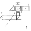
Fig. 4, demonstrates a hybrid situation for an inventive illumination unit 10
where for two different spectral ranges a high pressure lamp 12 is used as a part
of said light source device. Additionally, a solid state light source device 11 is
employed in the embodiment of Fig. 4 to supply primary and therefore secondary
illumination light L1 and L2, respectively, of a color or spectral range
sufficiently contained in the light of the high pressure lamp 12 to improve the
color properties of the mixed light being emitted by the light mixing device 55
after the mixing process during which also the uniformization takes place.
The uniformization may take place before the mixing device and may be done by
using either fly-eye lenses or integration rods.
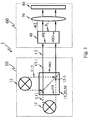
The embodiment of Fig. 5 is adapted to combine types of first primary
illumination light L1 from different light emitting diodes 31 or laser diodes
forming an array 33 and the first light source device 11 and having e.g. different
spectral or color properties with primary illumination light L12 of a UHP lamp
32 to form combined primary illumination light CL1 as well as secondary
illumination light L2.
In the embodiment of Fig. 5 second primary illumination light L12 from the UHP
lamp 32 forming a second light source device 12 enters the integration rod 51
forming the light integrating device 50 of the light collecting, integrating and
redirecting unit 20 directly through the front face of the light entrance section
50I, 51I or the main light entrance area 50I, 51I.
In contrast, first primary illumination light L11 from the different light emitting
diodes 31 enters the integration rod or integrator rod 51 through its side walls
or side faces 50s, 51s.
Additionally said integrator rod 51 comprises within its structure a plurality of
the above-mentioned light combining devices 15 in the form of dichroic band-pass
filters 15-3. Therefore, said combined primary illumination light CL1 is
formed simultaneously with an process of integrating and uniformizing the
different kinds of primary illumination light L11 and L12 with the structure of
the light collecting, integrating and redirecting unit 20.
List of Reference Symbols
- 1
- projection engine according to the present invention
- 10
- illumination unit according to the present invention
- 11
- first light source device
- 11c
- collimator, condenser device
- 11u
- uniformizer
- 11u-1
- first uniformizing integrator rod, first uniformizing light pipe
- 11u-2
- second uniformizing integrator rod, second uniformizing light pipe
- 12
- second light source device
- 15
- light combining area, portion or device
- 15-1
- first fly-eye lens system
- 15-2
- first fly-eye lens system
- 15-3
- dichroic band-pass filter
- 20
- light collecting, integrating and redirecting area, portion or unit
- 31
- solid state light source, LED
- 32
- discharge lamp, UHP lamp, HID lamp
- 32r
- reflector
- 33
- array of solid state light sources
- 40
- light valve device or unit
- 40I
- light input section, light entrance
- 40O
- light output section, light exit
- 50
- light integrating device
- 50I
- light input section, light entrance
- 50O
- light output section, light exit
- 50s
- inner walls, side walls
- 51
- integrator or integration rod, solid rod, light pipe
- 51I
- light input section, light entrance
- 51O
- light output section, light exit
- 51s
- inner walls, side walls
- 52
- fly-eye lens system
- 60
- display optics
- 70
- projection optics
- 80
- display screen
- L11
- first primary illumination light
- L12
- second primary illumination light
- L2
- secondary illumination light
- CL1
- combined primary illumination light
- S2
- illuminated or irradiating surface
- L
- lamp arrangement