EP1500923A2 - Infrared thermography imaging system with actively quenched lamp and method for actively controlling the flash duration - Google Patents
Infrared thermography imaging system with actively quenched lamp and method for actively controlling the flash duration Download PDFInfo
- Publication number
- EP1500923A2 EP1500923A2 EP04254380A EP04254380A EP1500923A2 EP 1500923 A2 EP1500923 A2 EP 1500923A2 EP 04254380 A EP04254380 A EP 04254380A EP 04254380 A EP04254380 A EP 04254380A EP 1500923 A2 EP1500923 A2 EP 1500923A2
- Authority
- EP
- European Patent Office
- Prior art keywords
- lamp
- control signal
- imaging system
- switch
- response
- Prior art date
- Legal status (The legal status is an assumption and is not a legal conclusion. Google has not performed a legal analysis and makes no representation as to the accuracy of the status listed.)
- Granted
Links
- 238000001931 thermography Methods 0.000 title claims abstract description 42
- 238000003384 imaging method Methods 0.000 title claims abstract description 31
- 238000000034 method Methods 0.000 title abstract description 19
- 238000010791 quenching Methods 0.000 claims abstract description 58
- 230000000171 quenching effect Effects 0.000 claims abstract description 45
- 230000004044 response Effects 0.000 claims abstract description 45
- 239000004065 semiconductor Substances 0.000 claims description 5
- 229910052736 halogen Inorganic materials 0.000 claims description 4
- 150000002367 halogens Chemical class 0.000 claims description 4
- 230000003213 activating effect Effects 0.000 abstract description 6
- 230000001052 transient effect Effects 0.000 description 7
- 238000010438 heat treatment Methods 0.000 description 4
- 230000006870 function Effects 0.000 description 3
- 238000005259 measurement Methods 0.000 description 3
- 238000012545 processing Methods 0.000 description 3
- XUIMIQQOPSSXEZ-UHFFFAOYSA-N Silicon Chemical compound [Si] XUIMIQQOPSSXEZ-UHFFFAOYSA-N 0.000 description 2
- 238000004891 communication Methods 0.000 description 2
- 238000010586 diagram Methods 0.000 description 2
- 239000000463 material Substances 0.000 description 2
- 238000009659 non-destructive testing Methods 0.000 description 2
- 230000002093 peripheral effect Effects 0.000 description 2
- 239000010453 quartz Substances 0.000 description 2
- 229910052710 silicon Inorganic materials 0.000 description 2
- 239000010703 silicon Substances 0.000 description 2
- VYPSYNLAJGMNEJ-UHFFFAOYSA-N silicon dioxide Inorganic materials O=[Si]=O VYPSYNLAJGMNEJ-UHFFFAOYSA-N 0.000 description 2
- 238000012360 testing method Methods 0.000 description 2
- 235000000177 Indigofera tinctoria Nutrition 0.000 description 1
- 238000013459 approach Methods 0.000 description 1
- 239000013078 crystal Substances 0.000 description 1
- 238000011156 evaluation Methods 0.000 description 1
- 229940097275 indigo Drugs 0.000 description 1
- COHYTHOBJLSHDF-UHFFFAOYSA-N indigo powder Natural products N1C2=CC=CC=C2C(=O)C1=C1C(=O)C2=CC=CC=C2N1 COHYTHOBJLSHDF-UHFFFAOYSA-N 0.000 description 1
- 238000003331 infrared imaging Methods 0.000 description 1
- 239000002905 metal composite material Substances 0.000 description 1
- 229910052755 nonmetal Inorganic materials 0.000 description 1
- 230000003287 optical effect Effects 0.000 description 1
- 239000007787 solid Substances 0.000 description 1
- 230000002123 temporal effect Effects 0.000 description 1
Images

Classifications
-
- G—PHYSICS
- G01—MEASURING; TESTING
- G01N—INVESTIGATING OR ANALYSING MATERIALS BY DETERMINING THEIR CHEMICAL OR PHYSICAL PROPERTIES
- G01N25/00—Investigating or analyzing materials by the use of thermal means
- G01N25/72—Investigating presence of flaws
Definitions
- the invention relates generally to infrared ("IR") thermography and, more particularly, to actively controlling the flash duration of an IR lamp for an IR thermography imaging system.
- IR infrared
- IR transient thermography is a versatile nondestructive testing technique that relies upon temporal measurements of heat transference through an object to provide information concerning the structure and integrity of the object. Because heat flow through an object is substantially unaffected by the microstructure and the single-crystal orientations of the material of the object, an IR transient thermography analysis is essentially free of the limitations this creates for ultrasonic measurements, which are another type of nondestructive evaluation used to determine wall thickness. In contrast to most ultrasonic techniques, a transient thermographic analysis approach is not significantly hampered by the size, contour or shape of the object being tested and, moreover, can be accomplished ten to one-hundred times faster than most conventional ultrasonic methods if testing objects of large surface area.
- the size and a value indicative of a "relative" depth of a flaw can be determined based upon a careful analysis of the temperature changes occurring at each resolution element over the surface of the object.
- the surface of an object must be heated to a particular temperature in a sufficiently short period of time, so as to preclude any significant heating of the remainder of the object.
- a quartz lamp or a high intensity flashlamp is conventionally used to generate a heat pulse of the proper magnitude and duration.
- an IR video camera has been used to record and store successive thermal images (frames) of an object surface after heating it.
- Each video image is composed of a fixed number of pixels.
- a pixel is a small picture element in an image array or frame, which corresponds to a rectangular area, called a "resolution element" on the surface of the object being imaged. Because the temperature at each resolution element is directly related to the intensity of the corresponding pixel, temperature changes at each resolution element on the object surface can be analyzed in terms of changes in pixel contrast.
- the contrast data for each pixel is then analyzed in the time domain (i.e., over many image frames) to identify the time of occurrence of an "inflection point" of the contrast curve data, which is mathematically related to a relative depth of a flaw within the object.
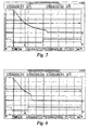
- FIG. 8 A conventional IR flash is shown in FIG. 8. As shown in FIG. 8, the flash has an exponential tail, which continues to heat the surface of the object.
- early frames When imaging thin parts, early frames must be analyzed and cannot be discarded.
- "early frames” refer to the frames at the beginning of a sequence of images.
- the thermal information in the early frames is distorted by the exponential tail of the flash because the exponential tail continues to heat the surface of the object during acquisition of the early frames. Consequently, the analysis of thin objects using IR thermography is currently limited due to the exponential tail of the flash.
- an actively quenched lamp includes a lamp and an active quenching means configured to quench the lamp.
- thermography imaging system includes at least one lamp configured to heat a surface of an object to be imaged, at least one active quenching means configured to quench the at least one lamp, and an IR camera configured to capture a number of IR image frames of the object.
- a method embodiment, for actively controlling a duration of a flash for IR thermography includes generating an initial control signal T0, a lamp control signal T1, and a control signal T2.
- the method further includes activating a quenching means in response to the initial control signal T0, to allow current I to flow to a lamp, activating the lamp in response to the lamp trigger signal T1, and turning off the quenching means in response to the control signal T2 to cut off the current I to the lamp.
- the actively quenched lamp 10 includes a lamp 12, and an active quenching means 14 configured to quench the lamp.
- Exemplary lamps 12 include quartz lamps and high power flash lamps driven by a power supply 36 and used for transient infrared imaging, such as halogen lamps, flash lamps, and arc lamps.
- One commercially available high power flash lamp is a Speedotron model 105 flash lamp, which can be driven by a Speedotron 4803, 4.8 Kilojoule (KJ) power supply, both of which are manufactured by Speedotron Corp., Chicago, III.
- the active quenching means 12 may be a discrete component of the actively quenched lamp 10, as shown in FIG. 1. Another configuration would be to include the active quenching means 12 within another component, for example, within the power supply 36 driving the lamp 12.
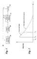
- FIG. 2 is an exemplary timing diagram for the actively quenched lamp 10.
- the active quenching means 14 is configured to receive an initial control signal T0 and to allow current I to flow to the lamp 12 in response to the initial control signal T0.
- the term "configured" means being equipped with circuitry, software and/or hardware for performing the stated function.
- the active quenching means 14 is configured to receive a control signal T2 and to quench the lamp 12 in response to the control signal T2.
- exemplary control signals T2 and T0 are the high and low portions, respectively, of a pulse signal.
- the actively quenched lamp 10 includes a timing generator 22 configured to supply the initial control and control signals T0, T2.
- the timing generator 22 may also supply a lamp trigger signal T1 to activate the lamp 12.
- An exemplary timing generator 22 is a computer. It should be noted that the present invention is not limited to any particular computer.
- the term "computer” is intended to denote any machine that is capable of accepting a structured input and of processing the input in accordance with prescribed rules to produce an output.
- One exemplary computer 22 is a specially programmed, general purpose digital computer that is capable of peripheral equipment control and communication functions, in addition to digital image processing and display.
- the decay time constant T of the lamp 12 is typically characterized by a resistance R and a power supply capacitance C.
- the time constant T governs the decay time for a flash.
- the flash has an exponential tail. This exponential tail would continue to heat the object during data acquisition, thereby distorting the thermal information in the data frames.
- a quenched flash is shown by the solid line.
- the desired duration D varies by application and is long enough to heat the surface of the object being inspected but short enough to end prior to acquisition of the data frames.
- An exemplary flash pulse has a desired duration of about 2 milliseconds.
- the active quenching means 14 reduces distortion of the thermal information in the data frames. In turn, reducing the distortion of the thermal information in the data frames permits a more accurate analysis.
- the desired pulse duration is equal to the infrared camera frame period used for the particular application. For example, if the camera operates at 500 frames per second (FPS), the frame period is 0.002 seconds, and the desired pulse duration should be set to 2 ms plus the appropriate pre-flash duration.
- FPS frames per second
- FIGS. 5-7 Exemplary quenched flashes are shown in FIGS. 5-7, and an exemplary unquenched flash is shown in FIG. 8.
- the quenched flashes in FIGS. 5-7 were cut off at 20 ms, 10 ms, and 2 ms, respectively.
- the flashes were monitored using a high-speed photodiode (not shown) and a digital storage scope (also not shown).
- FIGS. 5-8 demonstrate variable quenching collateral with the applied gate pulse.
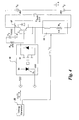
- FIG. 3 shows an exemplary active quenching means 14 in block form.
- the active quenching means 14 includes a high-voltage, high current switch 13.
- the switch 13 closes in response to the initial control signal T0, allowing current flow to the lamp 12, and opens in response to the control signal T2, quenching the lamp 12.
- Exemplary high-voltage, high current switches 13 include power semiconductor switches, such as an insulated gate bipolar transistor "IGBT" 17, as shown for example in FIG. 4, a silicon controlled rectifier (not shown), a gate turn-on thryristor (not shown), MOSFETS (not shown), and an integrated gate commutated thyristor (“IGCT”) (not shown).
- an IGBT 17 has a large current, large voltage standoff handling capacity.
- the IGBT 17 is relatively easy to control using its voltage-controlled gate.
- the IGBT 17 collector-emitter is in series with the lamp 12 current supply-line.
- the IGBT 17 has a voltage-controlled gate, which is turned on by an appropriate gate voltage V G . This closes the lamp circuit, allowing current I to flow to the lamp 12 and the flash to initiate.
- a gate driver was used to apply a 15 V delay-adjusted gate signal to the IGBT 17.
- the active quenching means 14 further includes a switch drive circuit 15 (or "gate drive circuit” 15) configured to receive a logic level signal and to generate a switch-drive signal in response.
- exemplary logic level signals include TTL, CMOS, and emitter coupled logic (ECL) signals.
- exemplary switch drive circuits 15 include an opto-coupler (as shown) and a logic level buffer and level shifter (not shown).
- An exemplary switch-drive signal is a voltage signal with sufficient magnitude to activate or deactivate a voltage-controlled switch 13, such as IGBT 17.
- the initial control signal T0 and the control signal T2 are logic level signals
- the high-voltage, high current switch 13 (here an IGBT 17) closes in response to the switch-drive voltage signal TS0 that corresponds to the initial control signal T0 and opens in response to the switch-drive voltage signal TS2 that corresponds to the control signal T2.
- Other exemplary switch-drive circuits 15 are configured to receive a logic level signal and to generate a switch-drive current signal in response, to activate or deactivate a current-controlled switch.
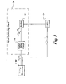
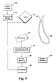
- thermography imaging system 30 An infrared (“IR") thermography imaging system 30 is described with reference to FIG. 9.
- the IR thermography imaging system 30 includes at least one lamp 12 configured to heat a surface 42 of an object 40 to be imaged.
- the exemplary object shown in FIG. 9 is an airfoil, the object 40 may take any form.
- the imaging system 30 also includes at least one active quenching means 14 configured to quench the at least one lamp 12, and an IR camera 32 configured to capture a number of IR image frames of the object 40.
- the active quenching means 14 and lamp 12 are described above.
- lamps 12 may be used to rapidly heat the surface 42.
- one suitable arrangement for the lamp(s) 12 is a set of four or eight high speed, high output power photographic flash lamps, each capable of about 4.8 Kilojoules output and having individual power supplies (such as manufactured by Speedotron. Corp., of Chicago, III.).
- An exemplary IR camera 36 is an IR video camera configured to record and store successive thermal images (frames) of the object surface 42 after heating by the lamp(s) 12.
- the IR camera may be an IR sensitive focal-plane camera available from Indigo Systems in Goleta, CA.
- the system 30 further includes a timing generator 22, such as a computer, which is configured to supply the initial control signal T0 and the control signal T2 to the quenching means 14.
- the timing generator 22 may be further configured to supply a lamp trigger signal T1 to activate the lamp 12.
- Camera and lamp control electronics 24 may be managed by video frame software running on the computer 22.
- an exemplary computer 22 is a specially programmed, general purpose digital computer that is capable of peripheral equipment control and communication functions, in addition to digital image processing and display.
- the computer 22 controls the camera and lamp electronics 24 and frame data memory 26 to acquire a predetermined number of successive thermal image frames of the object surface 42, which are stored in the frame data memory 26 for future analysis.
- a display monitor 28 may be provided.
- a method embodiment of the invention for actively controlling a duration of a flash for IR thermography, is also disclosed.
- the method includes generating an initial control signal T0, a lamp control signal T1, and a control signal T2.
- a quenching means 14 is activated in response to the initial control signal T0 to allow current I to flow to a lamp 12.
- the lamp is activated in response to the lamp trigger signal T1.
- the quenching means is turned off in response to the control signal T2, in order to cut off the current I to the lamp.
- the initial control signal T0 and the control signal T2 are logic level signals, such as TTL, CMOS, and emitter coupled logic (ECL) signals.
- the method also includes generating switch-drive signals TS0 and TS2 in response to the control signals T0 and T2, respectively.
- the quenching means is turned off by opening a switch in response to the switch-drive signal TS2 and is turned on by closing the switch in response to the switch drive signal TS0.
- the switch is voltage-controlled, and the switch-drive signals TS0 and TS2 are voltage signals.
Abstract
Description
- The invention relates generally to infrared ("IR") thermography and, more particularly, to actively controlling the flash duration of an IR lamp for an IR thermography imaging system.
- IR transient thermography is a versatile nondestructive testing technique that relies upon temporal measurements of heat transference through an object to provide information concerning the structure and integrity of the object. Because heat flow through an object is substantially unaffected by the microstructure and the single-crystal orientations of the material of the object, an IR transient thermography analysis is essentially free of the limitations this creates for ultrasonic measurements, which are another type of nondestructive evaluation used to determine wall thickness. In contrast to most ultrasonic techniques, a transient thermographic analysis approach is not significantly hampered by the size, contour or shape of the object being tested and, moreover, can be accomplished ten to one-hundred times faster than most conventional ultrasonic methods if testing objects of large surface area.
- One known contemporary application of transient thermography, which provides the ability to determine the size and "relative" location (depth) of flaws within solid non-metal composites, is revealed in U.S. Pat. No. 5,711,603 to Ringermacher et al., entitled "Nondestructive Testing: Transient Depth Thermography." Basically, this technique involves heating the surface of an object of interest and recording the temperature changes over time of very small regions or "resolution elements" on the surface of the object. These surface temperature changes are related to characteristic dynamics of heat flow through the object, which is affected by the presence of flaws. Accordingly, the size and a value indicative of a "relative" depth of a flaw (i.e., relative to other flaws within the object) can be determined based upon a careful analysis of the temperature changes occurring at each resolution element over the surface of the object.
- To obtain accurate thermal measurements using transient thermography, the surface of an object must be heated to a particular temperature in a sufficiently short period of time, so as to preclude any significant heating of the remainder of the object. Depending on the thickness and material characteristics of the object under test, a quartz lamp or a high intensity flashlamp is conventionally used to generate a heat pulse of the proper magnitude and duration. Once the surface of the object is heated, a graphic record of thermal changes over the surface is acquired and analyzed.
- Conventionally, an IR video camera has been used to record and store successive thermal images (frames) of an object surface after heating it. Each video image is composed of a fixed number of pixels. In this context, a pixel is a small picture element in an image array or frame, which corresponds to a rectangular area, called a "resolution element" on the surface of the object being imaged. Because the temperature at each resolution element is directly related to the intensity of the corresponding pixel, temperature changes at each resolution element on the object surface can be analyzed in terms of changes in pixel contrast. The contrast data for each pixel is then analyzed in the time domain (i.e., over many image frames) to identify the time of occurrence of an "inflection point" of the contrast curve data, which is mathematically related to a relative depth of a flaw within the object.
- As noted above, data acquisition begins after the surface of the object being inspected is heated by an IR flash. A conventional IR flash is shown in FIG. 8. As shown in FIG. 8, the flash has an exponential tail, which continues to heat the surface of the object. When imaging thin parts, early frames must be analyzed and cannot be discarded. As used here, "early frames" refer to the frames at the beginning of a sequence of images. However, the thermal information in the early frames is distorted by the exponential tail of the flash because the exponential tail continues to heat the surface of the object during acquisition of the early frames. Consequently, the analysis of thin objects using IR thermography is currently limited due to the exponential tail of the flash.
- Accordingly, it would be desirable to control the duration of the flash for IR thermography. Moreover, it would be desirable to actively control the duration of the flash for IR thermography, so that the desired flash duration may be selected for a given application.
- Briefly, in accordance with one embodiment of the present invention, an actively quenched lamp includes a lamp and an active quenching means configured to quench the lamp.
- An infrared ("IR") thermography imaging system embodiment is also disclosed. The IR thermography imaging system includes at least one lamp configured to heat a surface of an object to be imaged, at least one active quenching means configured to quench the at least one lamp, and an IR camera configured to capture a number of IR image frames of the object.
- A method embodiment, for actively controlling a duration of a flash for IR thermography, is also disclosed. The method includes generating an initial control signal T0, a lamp control signal T1, and a control signal T2. The method further includes activating a quenching means in response to the initial control signal T0, to allow current I to flow to a lamp, activating the lamp in response to the lamp trigger signal T1, and turning off the quenching means in response to the control signal T2 to cut off the current I to the lamp.
- The invention will now be described in greater detail, by way of example, with reference to the drawings, in which:-
- FIG. 1 illustrates an actively quenched lamp embodiment of the invention, in block form;
- FIG. 2 shows an exemplary timing diagram for the actively quenched lamp of FIG. 1;
- FIG. 3 shows an example of an active quenching means, in block form;
- FIG. 4 shows exemplary circuitry for the actively quenched lamp of FIGS. 1 and 3;
- Fig. 5 shows a quenched flash that was cut off at 20 ms;
- Fig. 6 shows a quenched flash that was cut off at 10 ms;
- Fig. 7 shows a quenched flash that was cut off at 2 ms;
- FIG. 8 shows an unquenched flash; and
- FIG. 9 illustrates an infrared thermography imaging system embodiment of the invention.
-
- An actively quenched
lamp 10 embodiment of the invention is described first with reference to FIGS. 1 and 2. As shown in FIG. 1, the actively quenchedlamp 10 includes alamp 12, and an active quenching means 14 configured to quench the lamp.Exemplary lamps 12 include quartz lamps and high power flash lamps driven by apower supply 36 and used for transient infrared imaging, such as halogen lamps, flash lamps, and arc lamps. One commercially available high power flash lamp is a Speedotron model 105 flash lamp, which can be driven by a Speedotron 4803, 4.8 Kilojoule (KJ) power supply, both of which are manufactured by Speedotron Corp., Chicago, III. - The active quenching means 12 may be a discrete component of the actively quenched
lamp 10, as shown in FIG. 1. Another configuration would be to include the active quenching means 12 within another component, for example, within thepower supply 36 driving thelamp 12. - FIG. 2 is an exemplary timing diagram for the actively
quenched lamp 10. As indicated in FIGS. 1 and 2, the active quenching means 14 is configured to receive an initial control signal T0 and to allow current I to flow to thelamp 12 in response to the initial control signal T0. As used herein, the term "configured" means being equipped with circuitry, software and/or hardware for performing the stated function. In addition, the active quenching means 14 is configured to receive a control signal T2 and to quench thelamp 12 in response to the control signal T2. As indicated in FIG. 3, for example, exemplary control signals T2 and T0 are the high and low portions, respectively, of a pulse signal. - For the embodiment of FIG. 1, the actively quenched
lamp 10 includes atiming generator 22 configured to supply the initial control and control signals T0, T2. Thetiming generator 22 may also supply a lamp trigger signal T1 to activate thelamp 12. Anexemplary timing generator 22 is a computer. It should be noted that the present invention is not limited to any particular computer. The term "computer" is intended to denote any machine that is capable of accepting a structured input and of processing the input in accordance with prescribed rules to produce an output. Oneexemplary computer 22 is a specially programmed, general purpose digital computer that is capable of peripheral equipment control and communication functions, in addition to digital image processing and display. - The decay time constant T of the
lamp 12 is typically characterized by a resistance R and a power supply capacitance C. The time constant T governs the decay time for a flash. As shown in FIG. 2 by the dashed line, without quenching, the flash has an exponential tail. This exponential tail would continue to heat the object during data acquisition, thereby distorting the thermal information in the data frames. A quenched flash is shown by the solid line. As shown, the flash has a duration D of about D=T2-T1. The desired duration D varies by application and is long enough to heat the surface of the object being inspected but short enough to end prior to acquisition of the data frames. An exemplary flash pulse has a desired duration of about 2 milliseconds. Beneficially, by cutting off the exponential tail (shown by the dashed line in FIG. 2), the active quenching means 14 reduces distortion of the thermal information in the data frames. In turn, reducing the distortion of the thermal information in the data frames permits a more accurate analysis. - More particularly, the desired pulse duration is equal to the infrared camera frame period used for the particular application. For example, if the camera operates at 500 frames per second (FPS), the frame period is 0.002 seconds, and the desired pulse duration should be set to 2 ms plus the appropriate pre-flash duration.
- Exemplary quenched flashes are shown in FIGS. 5-7, and an exemplary unquenched flash is shown in FIG. 8. The quenched flashes in FIGS. 5-7 were cut off at 20 ms, 10 ms, and 2 ms, respectively. The flashes were monitored using a high-speed photodiode (not shown) and a digital storage scope (also not shown). FIGS. 5-8 demonstrate variable quenching collateral with the applied gate pulse.
- FIG. 3 shows an exemplary active quenching means 14 in block form. As shown, the active quenching means 14 includes a high-voltage, high
current switch 13. Theswitch 13 closes in response to the initial control signal T0, allowing current flow to thelamp 12, and opens in response to the control signal T2, quenching thelamp 12. Exemplary high-voltage, highcurrent switches 13 include power semiconductor switches, such as an insulated gate bipolar transistor "IGBT" 17, as shown for example in FIG. 4, a silicon controlled rectifier (not shown), a gate turn-on thryristor (not shown), MOSFETS (not shown), and an integrated gate commutated thyristor ("IGCT") (not shown). Beneficially, anIGBT 17 has a large current, large voltage standoff handling capacity. In addition, theIGBT 17 is relatively easy to control using its voltage-controlled gate. - For the exemplary embodiment of FIG. 4, the
IGBT 17 collector-emitter is in series with thelamp 12 current supply-line. As noted above, theIGBT 17 has a voltage-controlled gate, which is turned on by an appropriate gate voltage VG. This closes the lamp circuit, allowing current I to flow to thelamp 12 and the flash to initiate. For the example shown in FIG. 4, a gate driver was used to apply a 15 V delay-adjusted gate signal to theIGBT 17. The end of the gate pulse, adjusted by the timing generator (or delay generator) 22, opens the lamp circuit, thereby cutting off the exponential tail of the flash at a chosen delay time, in order to produce a more rectangular shaped optical pulse, as indicated in FIG. 2 by the solid line. - For the embodiments of FIGS. 3 and 4, the active quenching means 14 further includes a switch drive circuit 15 (or "gate drive circuit" 15) configured to receive a logic level signal and to generate a switch-drive signal in response. Exemplary logic level signals include TTL, CMOS, and emitter coupled logic (ECL) signals. Exemplary
switch drive circuits 15 include an opto-coupler (as shown) and a logic level buffer and level shifter (not shown). An exemplary switch-drive signal is a voltage signal with sufficient magnitude to activate or deactivate a voltage-controlledswitch 13, such asIGBT 17. For this embodiment, the initial control signal T0 and the control signal T2 are logic level signals, and the high-voltage, high current switch 13 (here an IGBT 17) closes in response to the switch-drive voltage signal TS0 that corresponds to the initial control signal T0 and opens in response to the switch-drive voltage signal TS2 that corresponds to the control signal T2. Other exemplary switch-drive circuits 15 are configured to receive a logic level signal and to generate a switch-drive current signal in response, to activate or deactivate a current-controlled switch. - An infrared ("IR") thermography imaging system 30 is described with reference to FIG. 9. As shown, the IR thermography imaging system 30 includes at least one
lamp 12 configured to heat asurface 42 of anobject 40 to be imaged. Although the exemplary object shown in FIG. 9 is an airfoil, theobject 40 may take any form. The imaging system 30 also includes at least one active quenching means 14 configured to quench the at least onelamp 12, and anIR camera 32 configured to capture a number of IR image frames of theobject 40. The active quenching means 14 andlamp 12 are described above. - Depending on the size, thickness and other factors of the
object 40,several lamps 12 may be used to rapidly heat thesurface 42. For example, one suitable arrangement for the lamp(s) 12 is a set of four or eight high speed, high output power photographic flash lamps, each capable of about 4.8 Kilojoules output and having individual power supplies (such as manufactured by Speedotron. Corp., of Chicago, III.). - An
exemplary IR camera 36 is an IR video camera configured to record and store successive thermal images (frames) of theobject surface 42 after heating by the lamp(s) 12. For example, the IR camera may be an IR sensitive focal-plane camera available from Indigo Systems in Goleta, CA. - For the IR thermography imaging system 30 embodiment of FIG. 9, the system 30 further includes a
timing generator 22, such as a computer, which is configured to supply the initial control signal T0 and the control signal T2 to the quenching means 14. Thetiming generator 22 may be further configured to supply a lamp trigger signal T1 to activate thelamp 12. - Camera and
lamp control electronics 24 may be managed by video frame software running on thecomputer 22. As noted above, anexemplary computer 22 is a specially programmed, general purpose digital computer that is capable of peripheral equipment control and communication functions, in addition to digital image processing and display. For the embodiment of FIG. 9, thecomputer 22 controls the camera andlamp electronics 24 andframe data memory 26 to acquire a predetermined number of successive thermal image frames of theobject surface 42, which are stored in theframe data memory 26 for future analysis. In addition, adisplay monitor 28 may be provided. - A method embodiment of the invention, for actively controlling a duration of a flash for IR thermography, is also disclosed. The method includes generating an initial control signal T0, a lamp control signal T1, and a control signal T2. A quenching means 14 is activated in response to the initial control signal T0 to allow current I to flow to a
lamp 12. The lamp is activated in response to the lamp trigger signal T1. The quenching means is turned off in response to the control signal T2, in order to cut off the current I to the lamp. - According to a more particular embodiment of the method, the initial control signal T0 and the control signal T2 are logic level signals, such as TTL, CMOS, and emitter coupled logic (ECL) signals. For this embodiment, the method also includes generating switch-drive signals TS0 and TS2 in response to the control signals T0 and T2, respectively. The quenching means is turned off by opening a switch in response to the switch-drive signal TS2 and is turned on by closing the switch in response to the switch drive signal TS0. According to a particular embodiment, the switch is voltage-controlled, and the switch-drive signals TS0 and TS2 are voltage signals.
- For the sake of good order, various aspects of the invention are set out in the following clauses:-
- 1. An actively quenched lamp comprising:
- a lamp; and
- an active quenching means configured to quench said lamp.
- 2. The actively quenched lamp of
Clause 1, wherein said active quenching means is configured to receive a control signal T2 and to quench said lamp in response to the control signal T2. - 3. The actively quenched lamp of
Clause 2, wherein said active quenching means comprises a high-voltage, high current switch, wherein said high-voltage, high current switch opens in response to the control signal T2. - 4. The actively quenched lamp of
Clause 3, wherein said active quenching means is further configured to receive an initial control signal T0, and wherein said high-voltage, high current switch closes in response to the initial control signal T0. - 5. The actively quenched lamp of
Clause 3, further comprising a timing generator configured to supply the control and initial control signals T2, T0 and to supply a lamp trigger signal T1, wherein said lamp is activated in response to the lamp trigger signal T1. - 6. The actively quenched lamp of
Clause 3, wherein said timing generator comprises a computer. - 7. The actively quenched lamp of
Clause 3, wherein said active quenching means further comprises a switch drive circuit configured to receive a logic level signal and to generate a switch-drive signal in response, wherein the control signal T2 is a logic level signal, and wherein said high-voltage, high current switch opens in response to the switch-drive signal TS2 that corresponds to the control signal T2. - 8. The actively quenched lamp of Clause 7, wherein the switch-drive signal TS2 is a switch-drive voltage signal TS2.
- 9. The actively quenched lamp of
Clause 3, wherein said high-voltage, high current switch comprises a power semiconductor switch. - 10. The actively quenched lamp of
Clause 3, wherein said high-voltage, high current switch comprises an insulated gate bipolar transistor (IGBT). - 11. The actively quenched lamp of Clause 9, wherein the power semiconductor switch is selected from the group consisting of a silicon controlled rectifier, a gate turn-on thryristor, a MOSFET, a insulated gate commutated thyristor ("IGCT"), and combinations thereof.
- 12. The actively quenched lamp of
Clause 1, wherein said lamp comprises a halogen lamp. - 13. The actively quenched lamp of
Clause 1, wherein said lamp comprises a flash lamp. - 14. The actively quenched lamp of
Clause 1, wherein said lamp comprises an arc lamp. - 15. An infrared ("IR") thermography imaging system comprises:
- at least one lamp configured to heat a surface of an object to be imaged;
- at least one active quenching means configured to quench said at least one lamp; and
- an IR camera configured to capture a plurality of IR image frames of the object.
- 16. The IR thermography imaging system of
Clause 15, wherein said active quenching means is configured to receive an initial control signal T0 and a control signal T2, and wherein said active quenching means is further configured to allow a current flow I to said lamp in response to the initial control signal T0 and to quench said lamp in response to the control signal T2. - 17. The IR thermography imaging system of Clause 16, wherein said active quenching means comprises a high-voltage, high current switch, wherein said high-voltage, high current switch closes in response to the initial control signal T0 and opens in response to the control signal T2.
- 18. The IR thermography imaging system of
Clause 17, further comprising a timing generator configured to supply the initial control signal T0 and the control signal T2 and to supply a lamp trigger signal T1, wherein said lamp is activated in response to the lamp trigger signal T1. - 19. The IR thermography imaging system of Clause 16, wherein said active quenching means further comprises a switch drive circuit configured to receive a logic level signal and to generate a switch-drive signal in response, wherein the control signal T2 is a logic level signal, and wherein said high-voltage, high current switch opens in response to the switch-drive signal that corresponds to the control signal T2.
- 20. The IR thermography imaging system of Clause 19, wherein the switch-drive signal is a switch-drive voltage signal.
- 21. The IR thermography imaging system of
Clause 17, wherein said high-voltage, high current switch comprises a power semiconductor switch. - 22. The IR thermography imaging system of
Clause 17, wherein said high-voltage, high current switch comprises an insulated gate bipolar transistor. - 23. The IR thermography imaging system of
Clause 22, wherein said lamp comprises a halogen lamp. - 24. The IR thermography imaging system of
Clause 22, wherein said lamp comprises a flash lamp. - 25. A method for actively controlling a duration of a flash for infrared ("IR")
thermography, said method comprising:
- generating an initial control signal T0, a lamp control signal T1, and a control signal T2;
- activating a quenching means in response to the initial control signal T0 to allow current I to flow to a lamp; activating the lamp in response to the lamp trigger signal T1; and
- turning off the quenching means in response to the control signal T2 to cut off the current I to the lamp.
- 26. The method of Clause 25, wherein the initial control signal T0 and the
control signal T2 comprise logic level signals, and wherein said method
further comprises:
- generating a switch-drive signal TS2 in response to the control signal T2, wherein said turning off the quenching means comprises opening a switch in response to the switch-drive signal TS2.
- 27. The method of
Clause 26, wherein the switch-drive signal TS2 is a switch-drive voltage signal TS2. -
Claims (10)
- An infrared ("IR") thermography imaging system (30) comprises:t least one lamp (12) configured to heat a surface (42) of an object (40) to be imaged;at least one active quenching means (14) configured to quench said at least one lamp; andan IR camera (32) configured to capture a plurality of IR image frames of the object.
- The IR thermography imaging system (30) of Claim 1, wherein said active quenching means (14) is configured to receive an initial control signal T0 and a control signal T2, and wherein said active quenching means is further configured to allow a current flow I to said lamp (12) in response to the initial control signal T0 and to quench said lamp in response to the control signal T2.
- The IR thermography imaging system (30) of Claim 2, wherein said active quenching means (14) comprises a high-voltage, high current switch (13), wherein said high-voltage, high current switch closes in response to the initial control signal T0 and opens in response to the control signal T2.
- The IR thermography imaging system (30) of Claim 3, further comprising a timing generator (22) configured to supply the initial control signal T0 and the control signal T2 and to supply a lamp trigger signal T1, wherein said lamp (12) is activated in response to the lamp trigger signal T1.
- The IR thermography imaging system (30) of Claim 2, wherein said active quenching means (14) further comprises a switch drive circuit (15) configured to receive a logic level signal and to generate a switch-drive signal in response, wherein the control signal T2 is a logic level signal, and wherein said high-voltage, high current switch (13) opens in response to the switch-drive signal that corresponds to the control signal T2.
- The IR thermography imaging system (30) of Claim 5, wherein the switch-drive signal is a switch-drive voltage signal.
- The IR thermography imaging system (30) of Claim 3, wherein said high-voltage, high current switch (13) comprises a power semiconductor switch.
- The IR thermography imaging system (30) of Claim 3, wherein said high-voltage, high current switch (13) comprises an insulated gate bipolar transistor (17).
- The IR thermography imaging system (30) of Claim 8, wherein said lamp (12) comprises a halogen lamp.
- The IR thermography imaging system (30) of Claim 8, wherein said lamp (12) comprises a flash lamp.
Applications Claiming Priority (2)
| Application Number | Priority Date | Filing Date | Title |
|---|---|---|---|
| US627206 | 2003-07-24 | ||
| US10/627,206 US20050018748A1 (en) | 2003-07-24 | 2003-07-24 | Actively quenched lamp, infrared thermography imaging system, and method for actively controlling flash duration |
Publications (3)
| Publication Number | Publication Date |
|---|---|
| EP1500923A2 true EP1500923A2 (en) | 2005-01-26 |
| EP1500923A3 EP1500923A3 (en) | 2005-04-13 |
| EP1500923B1 EP1500923B1 (en) | 2012-09-12 |
Family
ID=33490917
Family Applications (1)
| Application Number | Title | Priority Date | Filing Date |
|---|---|---|---|
| EP04254380A Not-in-force EP1500923B1 (en) | 2003-07-24 | 2004-07-22 | Infrared thermography imaging system with actively quenched lamp and method for actively controlling the flash duration |
Country Status (3)
| Country | Link |
|---|---|
| US (1) | US20050018748A1 (en) |
| EP (1) | EP1500923B1 (en) |
| JP (1) | JP2005043369A (en) |
Families Citing this family (20)
| Publication number | Priority date | Publication date | Assignee | Title |
|---|---|---|---|---|
| US20150235094A1 (en) | 2014-02-17 | 2015-08-20 | General Electric Company | Vehicle imaging system and method |
| US11124207B2 (en) | 2014-03-18 | 2021-09-21 | Transportation Ip Holdings, Llc | Optical route examination system and method |
| US9875414B2 (en) | 2014-04-15 | 2018-01-23 | General Electric Company | Route damage prediction system and method |
| US9873442B2 (en) | 2002-06-04 | 2018-01-23 | General Electric Company | Aerial camera system and method for identifying route-related hazards |
| US20030222981A1 (en) * | 2002-06-04 | 2003-12-04 | Kisak Jeffrey James | Locomotive wireless video recorder and recording system |
| US7186981B2 (en) * | 2003-07-29 | 2007-03-06 | Thermal Wave Imaging, Inc. | Method and apparatus for thermographic imaging using flash pulse truncation |
| WO2007030941A1 (en) * | 2005-09-14 | 2007-03-22 | Mattson Technology Canada, Inc. | Repeatable heat-treating methods and apparatus |
| WO2008131513A1 (en) | 2007-05-01 | 2008-11-06 | Mattson Technology Canada, Inc. | Irradiance pulse heat-treating methods and apparatus |
| CN103460000B (en) * | 2010-03-17 | 2016-01-27 | 热波成像股份有限公司 | The thermal image detection that internal channel blocks |
| US9080453B2 (en) | 2010-03-17 | 2015-07-14 | Thermal Wave Imaging, Inc. | Thermographic detection of internal passageway blockages |
| US8356934B2 (en) * | 2010-08-06 | 2013-01-22 | Paul Allen Howard | Surrogate temperature sensor for a radiant heat source |
| US8692887B2 (en) * | 2010-08-27 | 2014-04-08 | General Electric Company | Thermal imaging method and apparatus for evaluating coatings |
| TWI421477B (en) * | 2010-08-30 | 2014-01-01 | Emcom Technology Inc | Temperature variation sensing apparatus and the method thereof |
| KR101733179B1 (en) | 2010-10-15 | 2017-05-08 | 맛선 테크놀러지, 인코포레이티드 | Methods, apparatus and media for determining a shape of an irradiance pulse to which a workpiece is to be exposed |
| CN102221339B (en) * | 2011-06-09 | 2012-09-05 | 首都师范大学 | Method for measuring thickness by pulse infrared thermal wave technology |
| US9500611B2 (en) | 2013-09-26 | 2016-11-22 | General Electric Company | Lamp assembly for a thermographic nondestructive evaluation system |
| US9481385B2 (en) | 2014-01-09 | 2016-11-01 | General Electric Company | Systems and methods for predictive maintenance of crossings |
| US10006877B2 (en) | 2014-08-20 | 2018-06-26 | General Electric Company | Route examining system and method |
| US10839509B2 (en) | 2015-07-10 | 2020-11-17 | 3Scan Inc. | Spatial multiplexing of histological stains |
| CN108225568A (en) * | 2017-12-26 | 2018-06-29 | 国网河北省电力有限公司衡水供电分公司 | High voltage side of transformer casing fault detection method |
Citations (1)
| Publication number | Priority date | Publication date | Assignee | Title |
|---|---|---|---|---|
| US6367969B1 (en) | 1999-07-21 | 2002-04-09 | General Electric Company | Synthetic reference thermal imaging method |
Family Cites Families (51)
| Publication number | Priority date | Publication date | Assignee | Title |
|---|---|---|---|---|
| US36060A (en) * | 1862-07-29 | Improvement in placing reservoirs for lamps | ||
| NL136888C (en) * | 1943-07-30 | |||
| US3555449A (en) * | 1966-11-15 | 1971-01-12 | Westinghouse Electric Corp | Liquid cooled laser system |
| US3781604A (en) * | 1972-04-13 | 1973-12-25 | Hope Tronics Ltd | Light control circuit |
| JPS581406B2 (en) * | 1975-03-03 | 1983-01-11 | ミノルタ株式会社 | Hatsukou Mushroom |
| JPS564132A (en) * | 1979-06-22 | 1981-01-17 | Yoshiyuki Takematsu | Flash device |
| US4299461A (en) * | 1980-03-31 | 1981-11-10 | Polaroid Corporation | Exposure and flash fire control system |
| DE3016897A1 (en) * | 1980-05-02 | 1981-11-05 | Robert Bosch Gmbh, 7000 Stuttgart | Remote control for electronic flash units - has IR transmitter and receiver and threshold signal activated by integrating circuit |
| JPS57118230A (en) * | 1980-07-24 | 1982-07-23 | Fuji Koeki Kk | Flash device |
| US4357083A (en) * | 1980-10-06 | 1982-11-02 | Polaroid Corporation | Method and apparatus using weighted range signal for controlling photographic functions |
| US4390959A (en) * | 1980-10-20 | 1983-06-28 | Johnson Controls, Inc. | Optimal start programmer |
| US4469989A (en) * | 1982-03-01 | 1984-09-04 | Fuji Koeki Corporation | Electric flash apparatus |
| US4534502A (en) * | 1983-02-14 | 1985-08-13 | Atlantic Richfield Company | Automatic solder machine |
| US4953951A (en) * | 1988-01-13 | 1990-09-04 | The United States Of America As Represented By The Secretary Of The Navy | Method for making holograms with coherent radiation from a stabilized laser diode that has been actively cooled |
| US4831410A (en) * | 1988-01-21 | 1989-05-16 | Xerox Corporation | Automatic exposure control system for flash exposure photocopiers |
| US5138361A (en) * | 1988-03-31 | 1992-08-11 | Asahi Kogaku Kogyo K.K. | Electronic flash control device employing a plurality of control signals |
| US4878116A (en) * | 1988-06-02 | 1989-10-31 | Wayne State University | Vector lock-in imaging system |
| US5041726A (en) * | 1990-06-11 | 1991-08-20 | Hughes Aircraft Company | Infrared holographic defect detector |
| US5105429A (en) * | 1990-07-06 | 1992-04-14 | The United States Of America As Represented By The Department Of Energy | Modular package for cooling a laser diode array |
| US5181215A (en) * | 1991-11-22 | 1993-01-19 | Sam Richard C | Heated solid state laser |
| JPH06341965A (en) * | 1993-06-03 | 1994-12-13 | Nippon Telegr & Teleph Corp <Ntt> | Inspection method for deterioration of painted film and its inspection device |
| US5422899A (en) * | 1994-05-10 | 1995-06-06 | Premier Laser Systems, Inc. | High repetition rate mid-infrared laser |
| US5790574A (en) * | 1994-08-24 | 1998-08-04 | Imar Technology Company | Low cost, high average power, high brightness solid state laser |
| US5539633A (en) * | 1994-12-09 | 1996-07-23 | Excel Energy Technologies, Ltd. | Temperature control method and apparatus |
| US5682562A (en) * | 1995-11-13 | 1997-10-28 | Eastman Kodak Company | Digitally controlled quench flash circuit |
| US20020018510A1 (en) * | 1996-07-31 | 2002-02-14 | Murphy John C. | Thermal-based methods for nondestructive evaluation |
| US5711603A (en) * | 1996-10-30 | 1998-01-27 | United Technologies Corporation | Nondestructive testing: transient depth thermography |
| WO1998022184A1 (en) * | 1996-11-21 | 1998-05-28 | Boston Scientific Corporation | Mucosal ablation using light |
| US6405137B1 (en) * | 1996-12-31 | 2002-06-11 | Ta Instruments, Inc. | Method and apparatus for performing chemical analysis using imaging by scanning thermal microscopy |
| JPH10320655A (en) * | 1997-05-15 | 1998-12-04 | Takahashi Works:Kk | Entry detection output device |
| ES2216115T3 (en) * | 1997-07-04 | 2004-10-16 | Sharp Kabushiki Kaisha | ELECTRICAL POWER CONTROL UNIT. |
| US6795784B1 (en) * | 1998-02-25 | 2004-09-21 | Thermal Wave Imaging, Inc. | Data integration and registration method and apparatus for non-destructive evaluation of materials |
| KR20000003800U (en) * | 1998-07-29 | 2000-02-25 | 구자홍 | Halogen lamp cooling structure of microwave oven |
| US6243403B1 (en) * | 1999-01-11 | 2001-06-05 | Agere Systems Optoelectronics Guardian Corp | Method and apparatus for integrated optical wavelength stabilization |
| US6394646B1 (en) * | 1999-04-16 | 2002-05-28 | General Electric Company | Method and apparatus for quantitative nondestructive evaluation of metal airfoils using high resolution transient thermography |
| US6367968B1 (en) * | 1999-07-21 | 2002-04-09 | General Electric Company | Thermal resonance imaging method |
| GB9924425D0 (en) * | 1999-10-16 | 1999-12-15 | British Aerospace | Material analysis |
| US6751342B2 (en) * | 1999-12-02 | 2004-06-15 | Thermal Wave Imaging, Inc. | System for generating thermographic images using thermographic signal reconstruction |
| JP2001201474A (en) * | 2000-01-19 | 2001-07-27 | Mitsubishi Heavy Ind Ltd | Apparatus for detecting internal defect of structure |
| JP3738678B2 (en) * | 2000-08-04 | 2006-01-25 | ウシオ電機株式会社 | Lamp unit for projector and dimming method thereof |
| AU2002219847A1 (en) * | 2000-11-15 | 2002-05-27 | Real Time Metrology, Inc. | Optical method and apparatus for inspecting large area planar objects |
| JP2002189008A (en) * | 2000-12-20 | 2002-07-05 | Mitsubishi Heavy Ind Ltd | Nondestructive inspecting method and device, and data determining device |
| US20020081111A1 (en) * | 2000-12-22 | 2002-06-27 | Hirohiko Ina | Hybrid camera fill-flash |
| US6665245B1 (en) * | 2000-12-22 | 2003-12-16 | Calimetrics | Optical disk initialization method and apparatus |
| US6517238B2 (en) * | 2001-01-18 | 2003-02-11 | The United States Of America As Represented By The United States Department Of Energy | Thermal imaging measurement of lateral diffusivity and non-invasive material defect detection |
| US6542849B2 (en) * | 2001-01-19 | 2003-04-01 | The University Of Chicago | Method for determining defect depth using thermal imaging |
| US6583588B2 (en) * | 2001-05-29 | 2003-06-24 | Koninklijke Philips Electronics N.V. | System and method of automatic cycling control for HID lamps |
| JP3925301B2 (en) * | 2001-07-12 | 2007-06-06 | コニカミノルタセンシング株式会社 | Spectral characteristic measuring apparatus and wavelength shift correction method for spectral sensitivity of the same |
| US6712502B2 (en) * | 2002-04-10 | 2004-03-30 | The United States Of America As Represented By The Administrator Of The National Aeronautics And Space Administration | Synchronized electronic shutter system and method for thermal nondestructive evaluation |
| US6937331B1 (en) * | 2003-01-30 | 2005-08-30 | The United States Of America As Represented By The Administrator Of The National Aeronautics And Space Administration | High-speed electromechanical shutter for imaging spectrographs |
| US7186981B2 (en) * | 2003-07-29 | 2007-03-06 | Thermal Wave Imaging, Inc. | Method and apparatus for thermographic imaging using flash pulse truncation |
-
2003
- 2003-07-24 US US10/627,206 patent/US20050018748A1/en not_active Abandoned
-
2004
- 2004-07-22 EP EP04254380A patent/EP1500923B1/en not_active Not-in-force
- 2004-07-23 JP JP2004215080A patent/JP2005043369A/en active Pending
Patent Citations (1)
| Publication number | Priority date | Publication date | Assignee | Title |
|---|---|---|---|---|
| US6367969B1 (en) | 1999-07-21 | 2002-04-09 | General Electric Company | Synthetic reference thermal imaging method |
Also Published As
| Publication number | Publication date |
|---|---|
| US20050018748A1 (en) | 2005-01-27 |
| EP1500923A3 (en) | 2005-04-13 |
| EP1500923B1 (en) | 2012-09-12 |
| JP2005043369A (en) | 2005-02-17 |
Similar Documents
| Publication | Publication Date | Title |
|---|---|---|
| EP1500923B1 (en) | Infrared thermography imaging system with actively quenched lamp and method for actively controlling the flash duration | |
| US4305658A (en) | Moving object inspection system | |
| KR100265672B1 (en) | Readout sustem and process for ir detector arrays | |
| CN108965734B (en) | Ultra-high speed imaging method based on synchronous control | |
| EP3001670A2 (en) | Efficient dark current subtraction in an image sensor | |
| US5331154A (en) | Rotary encoder for detecting a rotating position of a motor | |
| WO2013046859A1 (en) | Wiring inspecting method, wiring inspecting apparatus, wiring inspecting program, and recording medium | |
| JPS60226282A (en) | Image pickup device | |
| JP2001211375A (en) | Picture photographing device | |
| JP3661633B2 (en) | Electron beam test system and electron beam test method | |
| JPH1155563A (en) | Image acquiring device | |
| JP2631219B2 (en) | Automatic focusing device | |
| JP3308841B2 (en) | Camera device for electromagnetic wave detection | |
| JP4869837B2 (en) | Microscope imaging apparatus, microscope imaging program, and microscope imaging method | |
| JPH1154079A (en) | Electron microscopic operation-interlocking television camera | |
| JPH0365625A (en) | High-speed image pickup apparatus | |
| JPH11337511A (en) | Circuit inspection device, and method thereof | |
| Wang et al. | IR imaging of integrated circuit power transistors during operation | |
| JP2726379B2 (en) | IC defective part identification method | |
| JP3040616B2 (en) | Inspection device and inspection method | |
| JPH07140490A (en) | Short circuit inspecting method for tft substrate | |
| JPH0257754B2 (en) | ||
| US6856342B1 (en) | Control circuitry for high speed video camera operation | |
| JPS5846602Y2 (en) | Afterimage eraser | |
| EP0181031A2 (en) | Optimization of vidicon bias lighting |
Legal Events
| Date | Code | Title | Description |
|---|---|---|---|
| PUAI | Public reference made under article 153(3) epc to a published international application that has entered the european phase |
Free format text: ORIGINAL CODE: 0009012 |
|
| AK | Designated contracting states |
Kind code of ref document: A2 Designated state(s): AT BE BG CH CY CZ DE DK EE ES FI FR GB GR HU IE IT LI LU MC NL PL PT RO SE SI SK TR |
|
| AX | Request for extension of the european patent |
Extension state: AL HR LT LV MK |
|
| PUAL | Search report despatched |
Free format text: ORIGINAL CODE: 0009013 |
|
| AK | Designated contracting states |
Kind code of ref document: A3 Designated state(s): AT BE BG CH CY CZ DE DK EE ES FI FR GB GR HU IE IT LI LU MC NL PL PT RO SE SI SK TR |
|
| AX | Request for extension of the european patent |
Extension state: AL HR LT LV MK |
|
| 17P | Request for examination filed |
Effective date: 20051013 |
|
| AKX | Designation fees paid |
Designated state(s): DE FR GB |
|
| 17Q | First examination report despatched |
Effective date: 20110812 |
|
| GRAP | Despatch of communication of intention to grant a patent |
Free format text: ORIGINAL CODE: EPIDOSNIGR1 |
|
| GRAS | Grant fee paid |
Free format text: ORIGINAL CODE: EPIDOSNIGR3 |
|
| GRAA | (expected) grant |
Free format text: ORIGINAL CODE: 0009210 |
|
| AK | Designated contracting states |
Kind code of ref document: B1 Designated state(s): DE FR GB |
|
| REG | Reference to a national code |
Ref country code: GB Ref legal event code: FG4D |
|
| REG | Reference to a national code |
Ref country code: DE Ref legal event code: R096 Ref document number: 602004039275 Country of ref document: DE Effective date: 20121108 |
|
| PLBE | No opposition filed within time limit |
Free format text: ORIGINAL CODE: 0009261 |
|
| 26N | No opposition filed |
Effective date: 20130613 |
|
| REG | Reference to a national code |
Ref country code: DE Ref legal event code: R097 Ref document number: 602004039275 Country of ref document: DE Effective date: 20130613 |
|
| REG | Reference to a national code |
Ref country code: FR Ref legal event code: PLFP Year of fee payment: 13 |
|
| PGFP | Annual fee paid to national office [announced via postgrant information from national office to epo] |
Ref country code: DE Payment date: 20160726 Year of fee payment: 13 Ref country code: GB Payment date: 20160727 Year of fee payment: 13 |
|
| PGFP | Annual fee paid to national office [announced via postgrant information from national office to epo] |
Ref country code: FR Payment date: 20160726 Year of fee payment: 13 |
|
| REG | Reference to a national code |
Ref country code: DE Ref legal event code: R061 Ref document number: 602004039275 Country of ref document: DE |
|
| PLBR | Kind of request for revocation recorded |
Free format text: ORIGINAL CODE: EPIDOSNRVR2 |
|
| PLBT | Request for revocation filed by patent holder |
Free format text: ORIGINAL CODE: EPIDOSNRVR1 |
|
| PLDH | Decision on request for revocation |
Free format text: ORIGINAL CODE: EPIDOSNRVR3 |
|
| RDAA | Patent revoked on request of proprietor |
Free format text: ORIGINAL CODE: 0009220 |
|
| PLBU | Request for revocation filed by patent holder |
Free format text: ORIGINAL CODE: EPIDOSNRVR6 |
|
| STAA | Information on the status of an ep patent application or granted ep patent |
Free format text: STATUS: PATENT REVOKED BY PROPRIETOR |
|
| REG | Reference to a national code |
Ref country code: DE Ref legal event code: R064 Ref document number: 602004039275 Country of ref document: DE Ref country code: DE Ref legal event code: R103 Ref document number: 602004039275 Country of ref document: DE |
|
| RVAA | Request for revocation filed after opposition period found admissible |
Filing date: 20161215 Effective date: 20170201 |
|
| GBPC | Gb: european patent ceased through non-payment of renewal fee |
Effective date: 20170722 |
|
| REG | Reference to a national code |
Ref country code: FR Ref legal event code: ST Effective date: 20180330 |