EP1501669B1 - Smoothing method for layered deposition modeling - Google Patents
Smoothing method for layered deposition modeling Download PDFInfo
- Publication number
- EP1501669B1 EP1501669B1 EP03716969A EP03716969A EP1501669B1 EP 1501669 B1 EP1501669 B1 EP 1501669B1 EP 03716969 A EP03716969 A EP 03716969A EP 03716969 A EP03716969 A EP 03716969A EP 1501669 B1 EP1501669 B1 EP 1501669B1
- Authority
- EP
- European Patent Office
- Prior art keywords
- solvent
- modeling material
- geometry
- representation
- selected portions
- Prior art date
- Legal status (The legal status is an assumption and is not a legal conclusion. Google has not performed a legal analysis and makes no representation as to the accuracy of the status listed.)
- Expired - Lifetime
Links
Images

Classifications
-
- B—PERFORMING OPERATIONS; TRANSPORTING
- B29—WORKING OF PLASTICS; WORKING OF SUBSTANCES IN A PLASTIC STATE IN GENERAL
- B29C—SHAPING OR JOINING OF PLASTICS; SHAPING OF MATERIAL IN A PLASTIC STATE, NOT OTHERWISE PROVIDED FOR; AFTER-TREATMENT OF THE SHAPED PRODUCTS, e.g. REPAIRING
- B29C41/00—Shaping by coating a mould, core or other substrate, i.e. by depositing material and stripping-off the shaped article; Apparatus therefor
- B29C41/02—Shaping by coating a mould, core or other substrate, i.e. by depositing material and stripping-off the shaped article; Apparatus therefor for making articles of definite length, i.e. discrete articles
-
- B—PERFORMING OPERATIONS; TRANSPORTING
- B29—WORKING OF PLASTICS; WORKING OF SUBSTANCES IN A PLASTIC STATE IN GENERAL
- B29C—SHAPING OR JOINING OF PLASTICS; SHAPING OF MATERIAL IN A PLASTIC STATE, NOT OTHERWISE PROVIDED FOR; AFTER-TREATMENT OF THE SHAPED PRODUCTS, e.g. REPAIRING
- B29C71/00—After-treatment of articles without altering their shape; Apparatus therefor
- B29C71/0009—After-treatment of articles without altering their shape; Apparatus therefor using liquids, e.g. solvents, swelling agents
-
- B—PERFORMING OPERATIONS; TRANSPORTING
- B29—WORKING OF PLASTICS; WORKING OF SUBSTANCES IN A PLASTIC STATE IN GENERAL
- B29C—SHAPING OR JOINING OF PLASTICS; SHAPING OF MATERIAL IN A PLASTIC STATE, NOT OTHERWISE PROVIDED FOR; AFTER-TREATMENT OF THE SHAPED PRODUCTS, e.g. REPAIRING
- B29C64/00—Additive manufacturing, i.e. manufacturing of three-dimensional [3D] objects by additive deposition, additive agglomeration or additive layering, e.g. by 3D printing, stereolithography or selective laser sintering
- B29C64/10—Processes of additive manufacturing
- B29C64/106—Processes of additive manufacturing using only liquids or viscous materials, e.g. depositing a continuous bead of viscous material
- B29C64/124—Processes of additive manufacturing using only liquids or viscous materials, e.g. depositing a continuous bead of viscous material using layers of liquid which are selectively solidified
- B29C64/129—Processes of additive manufacturing using only liquids or viscous materials, e.g. depositing a continuous bead of viscous material using layers of liquid which are selectively solidified characterised by the energy source therefor, e.g. by global irradiation combined with a mask
- B29C64/135—Processes of additive manufacturing using only liquids or viscous materials, e.g. depositing a continuous bead of viscous material using layers of liquid which are selectively solidified characterised by the energy source therefor, e.g. by global irradiation combined with a mask the energy source being concentrated, e.g. scanning lasers or focused light sources
-
- B—PERFORMING OPERATIONS; TRANSPORTING
- B29—WORKING OF PLASTICS; WORKING OF SUBSTANCES IN A PLASTIC STATE IN GENERAL
- B29C—SHAPING OR JOINING OF PLASTICS; SHAPING OF MATERIAL IN A PLASTIC STATE, NOT OTHERWISE PROVIDED FOR; AFTER-TREATMENT OF THE SHAPED PRODUCTS, e.g. REPAIRING
- B29C71/00—After-treatment of articles without altering their shape; Apparatus therefor
- B29C71/02—Thermal after-treatment
-
- B—PERFORMING OPERATIONS; TRANSPORTING
- B33—ADDITIVE MANUFACTURING TECHNOLOGY
- B33Y—ADDITIVE MANUFACTURING, i.e. MANUFACTURING OF THREE-DIMENSIONAL [3-D] OBJECTS BY ADDITIVE DEPOSITION, ADDITIVE AGGLOMERATION OR ADDITIVE LAYERING, e.g. BY 3-D PRINTING, STEREOLITHOGRAPHY OR SELECTIVE LASER SINTERING
- B33Y10/00—Processes of additive manufacturing
-
- B—PERFORMING OPERATIONS; TRANSPORTING
- B33—ADDITIVE MANUFACTURING TECHNOLOGY
- B33Y—ADDITIVE MANUFACTURING, i.e. MANUFACTURING OF THREE-DIMENSIONAL [3-D] OBJECTS BY ADDITIVE DEPOSITION, ADDITIVE AGGLOMERATION OR ADDITIVE LAYERING, e.g. BY 3-D PRINTING, STEREOLITHOGRAPHY OR SELECTIVE LASER SINTERING
- B33Y40/00—Auxiliary operations or equipment, e.g. for material handling
- B33Y40/20—Post-treatment, e.g. curing, coating or polishing
-
- B—PERFORMING OPERATIONS; TRANSPORTING
- B33—ADDITIVE MANUFACTURING TECHNOLOGY
- B33Y—ADDITIVE MANUFACTURING, i.e. MANUFACTURING OF THREE-DIMENSIONAL [3-D] OBJECTS BY ADDITIVE DEPOSITION, ADDITIVE AGGLOMERATION OR ADDITIVE LAYERING, e.g. BY 3-D PRINTING, STEREOLITHOGRAPHY OR SELECTIVE LASER SINTERING
- B33Y70/00—Materials specially adapted for additive manufacturing
-
- B—PERFORMING OPERATIONS; TRANSPORTING
- B29—WORKING OF PLASTICS; WORKING OF SUBSTANCES IN A PLASTIC STATE IN GENERAL
- B29C—SHAPING OR JOINING OF PLASTICS; SHAPING OF MATERIAL IN A PLASTIC STATE, NOT OTHERWISE PROVIDED FOR; AFTER-TREATMENT OF THE SHAPED PRODUCTS, e.g. REPAIRING
- B29C41/00—Shaping by coating a mould, core or other substrate, i.e. by depositing material and stripping-off the shaped article; Apparatus therefor
- B29C41/34—Component parts, details or accessories; Auxiliary operations
- B29C41/48—Compensating volume change, e.g. retraction
-
- B—PERFORMING OPERATIONS; TRANSPORTING
- B29—WORKING OF PLASTICS; WORKING OF SUBSTANCES IN A PLASTIC STATE IN GENERAL
- B29K—INDEXING SCHEME ASSOCIATED WITH SUBCLASSES B29B, B29C OR B29D, RELATING TO MOULDING MATERIALS OR TO MATERIALS FOR MOULDS, REINFORCEMENTS, FILLERS OR PREFORMED PARTS, e.g. INSERTS
- B29K2995/00—Properties of moulding materials, reinforcements, fillers, preformed parts or moulds
- B29K2995/0037—Other properties
- B29K2995/0072—Roughness, e.g. anti-slip
- B29K2995/0073—Roughness, e.g. anti-slip smooth
Definitions
- the present invention relates to the field of rapid prototyping, and particularly to methods of achieving surface smoothness in prototype objects made by layered manufacturing.
- layered manufacturing methods for forming three-dimensional prototypes are known, which develop prototype objects cheaply and quickly from a geometric computer model under computer control.
- These rapid prototyping methods generally slice or divide a digital representation of a desired object (computer aided design (CAD)) into horizontal layers, then build the object layer-by-layer by repetitive application of materials.
- CAD computer aided design
- Exemplary rapid prototyping techniques include layered deposition modeling, selective laser sintering and stereolithographic processes.
- layered deposition modeling is a fused deposition modeling technique performed by Stratasys® FDM® modeling machines.
- Fused deposition modeling builds up three-dimensional objects by extruding solidifiable modeling material from an extrusion head in a predetermined pattern, layer-by-layer, based upon design data corresponding to the particular shape of each object layer.
- extrusion-based apparatus and methods for making three-dimensional objects are described in Crump U.S. Patent No. 5,121,329 , Crump U.S. Patent No. 5,340,433 , Danforth et al. U.S. Patent No. 5,738,817 , Batchelder et al. U.S. Patent No. 5,764,521 and Dahlin et al. U.S. Patent No. 6,022,207 , all of which are assigned to Stratasys, Inc., the assignee of the present invention.
- modeling material is typically loaded into the machine as a flexible filament wound on a supply reel, such as disclosed in U.S. Patent No. 5,121,329 .
- a solidifiable material which adheres to the previous layer with an adequate bond upon solidification and which can be supplied as a flexible filament is used as the modeling material.
- Motor-driven feed rollers advance the strand of filament into a liquifier carried by an extrusion head. Inside the liquifier, the filament is heated to a flowable temperature. Flowable modeling material is forced out of a nozzle on the far end of the liquifier, and deposited from the liquifier onto a base.
- the flow rate of the material extruded from the nozzle is a function of the rate at which the filament is advanced to the extrusion head.
- a controller controls movement of the extrusion head in a horizontal x, y plane, controls movement of the base in a vertical z-direction, and controls the rate at which the feed rollers advance filament.
- the modeling material is deposited in "beads" layer-by-layer along tool paths defined from the CAD model.
- the material being extruded fuses to previously deposited material and solidifies to form a three-dimensional object resembling the CAD model.
- the surfaces of objects developed from layered manufacturing techniques of the current art are textured or striated due to their layered formation.
- Curved and angled surfaces generally have a "stair step" appearance, caused by layering of cross-sectional shapes which have square edge profiles.
- the stair-stepping effect is more pronounced as layer thickness increases. Although the stair-stepping does not effect the strength of the object, it does detract aesthetically.
- Rapid prototyping of three-dimensional objects includes not only the production of prototype parts, but also may include the production of molds.
- Exemplary uses of molds created with rapid prototyping include forming molds used to create injection molding tool inserts such as described in U.S. Patent No. 5,189,781 , and forming fugitive molds for green ceramic pieces prior to sintering such as described in U.S. Patent 5,824,250 and U.S. Patent 5,976,457 .
- 5,143,663 describes a method for removing excess resin from layered manufacturing prototype objects in a vapor degreaser, as per the preamble of claim 1. There is a need in rapid prototyping systems of an expedient and relatively inexpensive method of post-processing layered manufacturing prototype objects.
- solvent polishing A previously developed technique used in manufacturing of plastics involves the use of chemical vapors or liquids to smooth by reflowing the surface of the plastic, termed solvent polishing.
- Solvent polishing was developed in the plastics industry over twenty years ago for the purpose of developing a smooth level and/or high gloss coating or surface without needing to exercise extreme care in the application or manufacturing of the items.
- U.S. Patent No. 3,437,727 discloses a method using chemical vapors for refinishing telephones that were returned to the telephone company as a method of recycling them.
- the first is to immerse the entire plastic article in a bath of liquid plastic solvent for a period of time based on the solvent and type of plastic involved. This allows the solvent to penetrate the outer layer of the plastic, thereby causing it to reflow. Reflowing causes the outer surfaces of the plastic article to become smooth and/or shiny.
- the second method of solvent polishing is the exposure of the plastic article to vaporized solvent.
- a handheld vaporizer as shown in U.S. Patent No. 4,260,873 may be used to expose the plastic object.
- the object can be placed into a chamber filled with a vaporized solvent, generated from a heated bath below, as in U.S. Patent No. 3,737,499 .
- An advantage of the vaporizing chamber is that the solvent is contained and can be recycled, thereby minimizing potential environmental pollution.
- Solvent polishing using liquid or vapors is also commonly used as a degreasing or cleaning step in manufacturing processes, especially prior to painting.
- the present invention is a method for smoothing the surface of an object built from a polymeric or wax material using a layered manufacturing rapid prototyping technique. After the object is built, it is exposed to a vaporized solvent for an exposure time sufficient to reflow the object surface.
- a solvent is chosen based on its ability to transiently soften the material which forms the object, and thereafter evaporate off the object.
- the object is removed from the solvent and allowed to dry, producing a smooth finished part.
- portions of the object surface may be masked prior to exposing the object to solvent, so as to preserve fine details of the object.
- portions of the object surface may be pre-distorted prior to exposing the object to solvent, so that said surface portions will attain a desired geometry following vapor smoothing.
- the method of the present invention may be employed with respect to objects formed from a polymeric or wax material using layered manufacturing rapid prototyping techniques.
- An exemplary layered manufacturing technique is the type disclosed in U.S. Patent No. 5,121,329 , wherein an extrusion head deposits "roads" of molten material in layers of predetermined shape, and which material solidifies upon a drop in temperature to form a solid model.
- Figure 1 shows an exemplary object 10, formed by a layered manufacturing rapid prototyping technique.
- the object 10 has an angled surface 12, a curved surface 14, two horizontal surfaces 16, and three vertical surfaces 18.
- the object may be a mold tool for use in making prototype plastic injection molded parts, such as is disclosed in International Application No. PCT/US03/10219 entitled “Layered Deposition Bridge Tooling", S. Crump and J. Hanson, filed on even date herewith and assigned to the same assignee as the present application.
- the object 10 is made of a polymeric or wax modeling material, which may also include fillers and other additives as well as dispersed particulate materials.
- thermoplastics are particularly suited for use in the present invention, for instance, ABS, polycarbonate, polyphenylsulfone, polysulfone, polystyrene, polyphenylene ether, amorphous polyamides, acrylics, poly(2-ethyl-2-oxazoline), and blends thereof.
- the present invention may also be used to advantage with other polymeric and wax materials, including glass-filled nylon, jetting wax, sintered thermal plastic powders, and green metals or green ceramics dispersed in a polymeric binder.
- the object 10 is "raw", that is, it has not undergone post-process smoothing.
- surfaces 12 and 14 Prior to vapor smoothing in accordance with the present invention, surfaces 12 and 14 exhibit a stair-stepping effect.
- Surfaces 16 and 18 exhibit striation and roughness.
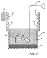
- a vaporizer 30 To smooth the surfaces of object 10, the object 10 is placed in a vaporizer 30, where it is exposed to vapors of a solvent 34. This is illustrated in FIG. 3 .
- a suitable vaporizer is of the type available from Detrex Corp. of Southfield, Michigan, model VS-2000, although those skilled in the art will recognize that many alternative vaporizers can be used in practicing the present invention.
- Vaporizer 30 is shown as having a control panel 31 for controlling operation of the vaporizer, and primary and secondary cooling coils, 33 and 35, respectively.
- the solvent 34 is selected to be compatible with the modeling material which forms the object 10. Suitable solvents will react with the modeling material so as to soften and flow the material at the object surfaces. The solvent should also be able to vaporize off the surface of the object, leaving the object intact and unscathed.
- a preferred solvent for use with a wide range of amorphous thermoplastics is methylene chloride.
- Other suitable solvents will be recognized by those skilled in the art, for instance, an n-Propyl bromide solution (e.g., Abzol®), perchloroethylene, trichloroethylene, and a hydrofluorocarbon fluid sold under the name Vertrel®.
- the vaporizer 30 boils the solvent 34 into a vapor zone 36, which is maintained at or above the boiling point of the solvent and contained by the cooling coils 33 and 35.
- the object 10 is suspended in the vapor zone 36, held by a wire skewer 32, which is bent to fit around the object.
- Alternative holding means may also be used, such as a basket, a net or a mesh platform.
- the object 10 is exposed to the vaporized solvent 34, allowing vapors of the solvent 34 to penetrate the surfaces 12, 14, 16 and 18 of object 10. Penetration of the solvent 34 softens the modeling material at the object surfaces, so that the surface material may reflow. Reflowing of the material smooths the object surfaces.
- the object 10 remains exposed to the vapors of solvent 34 until a desired surface finish is obtained.
- An exposure time is selected based on the type of solvent and modeling material, the fineness of the object features, and the concentration of the solvent vapors.
- the exposure time can be gauged by observing condensation of solvent vapors on the object, or can be pre-selected according to a formula. Condensation will stop when the temperature of the object surface reaches the temperature of the boiling solvent. This is an indication that solvent penetration has occurred.
- methylene chloride as the solvent 34, an amorphous thermoplastic modeling material will soften and reflow in a short time, typically between about 0.1 seconds to 5 minutes exposure time.
- the object 10 When the exposure time elapses, the object 10 is removed from the vapor zone 36 and allowed to dry. In a preferred embodiment, the object 10 dries within seconds to minutes after its removal from the vapor zone 36, as the solvent 34 evaporates off of the object 10. The object 10 may then be handled, as it is not sticky, soft or wet. In some cases, such as where solvent exposure time is great or the solvent is highly concentrated, it may be desirable to dry the object 10 in an oven to remove any residual solvent. Oven drying should be done at a temperature greater than the boiling point of the solvent.
- FIG. 2 illustrates a significant reduction in the stair steps and roughness of the object 10, achieved by vapor smoothing.
- selected features of an object can be masked with a substance that will inhibit smoothing of said selected portions, or, exposure of said selected features to the solvent vapors can be otherwise avoided.
- a substance that will inhibit smoothing of said selected portions e.g., it may be desirable to mask the corners of object 10, to prevent the corners from rounding.
- concave surfaces of an object can be masked to prevent in-flow of surrounding material.
- suitable solvent masking substances include those used in printed circuit board manufacturing, such as gums, waxes, pastes, adhesives or masking tape, which may be applied either manually or automatically. Masking may also be accomplished by surrounding a feature with a gas.
- Automatic application of a masking substrate may be done, for example, by jetting a masking material onto the surface of selected object features, in a layered deposition process such as is known in the art.
- a masking substance may also be applied by depositing roads of masking material, using a fused deposition modeling process such as performed by Stratasys® FDM® modeling machines. Those skilled in the art will recognize additional masking techniques know in the art, that may be applied in carrying out the present invention.
- the features to be masked may be identified using a software algorithm that creates a digital representation of the surface area to be protected.
- the protected area may be identified in a digital representation of the object, such as in an .stl file geometry using a CAD system, a Graphic Pixel system or a Voxel system.
- the surface areas to be masked may be identified by the user via a haptic input interface, such as a FreeForm TM system available from SensAble Technologies, Inc.
- the haptic input system creates a digital mask of the areas for which smoothing is not desired.
- the geometry of an object surface may be pre-distorted in anticipation of the vapor smoothing.
- the pre-distortion is accomplished by using a software algorithm to modify a digital representation of the object (e.g ., a CAD model of the object or a sliced representation of the object as in a .stl file).
- a software algorithm to modify a digital representation of the object (e.g ., a CAD model of the object or a sliced representation of the object as in a .stl file).
- a pre-distortion software algorithm feature details are distorted so as to overbuild corners and edges, and underbuild pockets, such that following vapor smoothing such features will attain approximately the desired geometry.
- an exemplary pre-distortion algorithm will: (1) identify geometric features with radii of curvature equal to or smaller than the slice height ( i .
- the algorithm will build up the initial object representation at such features; and (3) for identified geometric features having a negative radius of curvature (e.g ., a pocket or a joint between planes), the algorithm will hollow out the object representation in the vicinity of such features.
- the pre-distortion software algorithm thus creates a modified object representation, so that the identified geometric features will be distorted by either depositing additional material or depositing less material than is ultimately desired in the final smoothed object.
- a similar algorithm can be used to identify features for masking.
- features should be built up by not more than the slice height, for instance, by half of a slice height.
- the surface roughness of a typical part made by fused deposition modeling is about 0.3 times the slice height.
- the additional material added in pre-distortion of positive features may be roughly the thickness of this surface roughness, so that when the re-flowed material is pulled away, the solid material left takes on the desired final object geometry.
- enough material needs to be removed by the pre-distortion algorithm that the in-flow from the surrounding regions fills in the removed material.
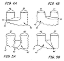
- FIGS. 4a and 4b and FIGS. 5a and 5b show a cross-sectional view of a portion of an object 40 that has not been pre-distorted, superimposed onto an outline 42 illustrating the desired final surface object geometry of object 40 ( i . e ., the unmodified object representation).
- vapor smoothing results in rounding of convex corners 44 away from the desired outline 42, and rounding of edges 46 beyond the desired outline 42.
- FIGS. 5a and 5b illustrate a portion of an object 40' which has the same desired final surface geometry as object 40.
- object 40' has been pre-distorted according to the pre-distortion algorithm of the present invention.
- the pre-distorted surface geometry of object 40 extends beyond the desired outline 42 at corners 44 and concave edges 46.
- the corners 44 and edges 46 of the pre-distorted object 40 more closely follow the desired outline 42 than do the corners 44 and edges 46 of the object 40.
Abstract
Description
- The present invention relates to the field of rapid prototyping, and particularly to methods of achieving surface smoothness in prototype objects made by layered manufacturing.
- Production and testing of prototype objects is a commonly used step in developing new products, machines and processes in a wide range of industries. A variety of layered manufacturing methods for forming three-dimensional prototypes are known, which develop prototype objects cheaply and quickly from a geometric computer model under computer control. These rapid prototyping methods generally slice or divide a digital representation of a desired object (computer aided design (CAD)) into horizontal layers, then build the object layer-by-layer by repetitive application of materials. Exemplary rapid prototyping techniques include layered deposition modeling, selective laser sintering and stereolithographic processes.
- One example of layered deposition modeling is a fused deposition modeling technique performed by Stratasys® FDM® modeling machines. Fused deposition modeling builds up three-dimensional objects by extruding solidifiable modeling material from an extrusion head in a predetermined pattern, layer-by-layer, based upon design data corresponding to the particular shape of each object layer. Examples of extrusion-based apparatus and methods for making three-dimensional objects are described in
Crump U.S. Patent No. 5,121,329 ,Crump U.S. Patent No. 5,340,433 ,Danforth et al. U.S. Patent No. 5,738,817 ,Batchelder et al. U.S. Patent No. 5,764,521 andDahlin et al. U.S. Patent No. 6,022,207 , all of which are assigned to Stratasys, Inc., the assignee of the present invention. - In the Stratasys® FDM® modeling machines of the current art, modeling material is typically loaded into the machine as a flexible filament wound on a supply reel, such as disclosed in
U.S. Patent No. 5,121,329 . A solidifiable material which adheres to the previous layer with an adequate bond upon solidification and which can be supplied as a flexible filament is used as the modeling material. Motor-driven feed rollers advance the strand of filament into a liquifier carried by an extrusion head. Inside the liquifier, the filament is heated to a flowable temperature. Flowable modeling material is forced out of a nozzle on the far end of the liquifier, and deposited from the liquifier onto a base. The flow rate of the material extruded from the nozzle is a function of the rate at which the filament is advanced to the extrusion head. A controller controls movement of the extrusion head in a horizontal x, y plane, controls movement of the base in a vertical z-direction, and controls the rate at which the feed rollers advance filament. By controlling these processing variables in synchrony, the modeling material is deposited in "beads" layer-by-layer along tool paths defined from the CAD model. The material being extruded fuses to previously deposited material and solidifies to form a three-dimensional object resembling the CAD model. - The surfaces of objects developed from layered manufacturing techniques of the current art are textured or striated due to their layered formation. Curved and angled surfaces generally have a "stair step" appearance, caused by layering of cross-sectional shapes which have square edge profiles. The stair-stepping effect is more pronounced as layer thickness increases. Although the stair-stepping does not effect the strength of the object, it does detract aesthetically.
- Surface roughness of objects created by layered manufacturing techniques also arises from errors in the build process. For example, in the fused deposition modeling systems of the current art, errors can arise due in part to inconsistent extrusion flow rates. Errors particularly occur at start points and end points of the tool path, for instance, at the location of a "seam" (i.e., the start and end point of a closed-loop tool path). These errors can cause undesired inconsistencies in the shape of the resulting model.
- Rapid prototyping of three-dimensional objects includes not only the production of prototype parts, but also may include the production of molds. Exemplary uses of molds created with rapid prototyping include forming molds used to create injection molding tool inserts such as described in
U.S. Patent No. 5,189,781 , and forming fugitive molds for green ceramic pieces prior to sintering such as described inU.S. Patent 5,824,250 andU.S. Patent 5,976,457 . - The current art teaches manually trimming, machining or grinding objects formed by layered manufacturing to remove excess material. Buffing with cloths, sand paper or solution-born abrasives are current methods of smoothing or polishing the objects. For example,
Hull et al. U.S. Patent 5,059,359 , Methods and Apparatus for Producing Three-dimensional Objects by Stereolithography, describes their prototypes as "perfect for smoothing by sanding to yield the right-sized part". The need for hand-finishing of models made from additive process techniques is also recognized inU.S. Patent No. 6,021,358 , which utilizes subtractive modeling techniques to attain smooth models.U.S. Patent no. 5,143,663 describes a method for removing excess resin from layered manufacturing prototype objects in a vapor degreaser, as per the preamble of claim 1. There is a need in rapid prototyping systems of an expedient and relatively inexpensive method of post-processing layered manufacturing prototype objects. - A previously developed technique used in manufacturing of plastics involves the use of chemical vapors or liquids to smooth by reflowing the surface of the plastic, termed solvent polishing. Solvent polishing was developed in the plastics industry over twenty years ago for the purpose of developing a smooth level and/or high gloss coating or surface without needing to exercise extreme care in the application or manufacturing of the items. For example,
U.S. Patent No. 3,437,727 discloses a method using chemical vapors for refinishing telephones that were returned to the telephone company as a method of recycling them. - There are two standard methods for solvent polishing articles. The first is to immerse the entire plastic article in a bath of liquid plastic solvent for a period of time based on the solvent and type of plastic involved. This allows the solvent to penetrate the outer layer of the plastic, thereby causing it to reflow. Reflowing causes the outer surfaces of the plastic article to become smooth and/or shiny.
- The second method of solvent polishing is the exposure of the plastic article to vaporized solvent. A handheld vaporizer as shown in
U.S. Patent No. 4,260,873 may be used to expose the plastic object. Alternatively, the object can be placed into a chamber filled with a vaporized solvent, generated from a heated bath below, as inU.S. Patent No. 3,737,499 . An advantage of the vaporizing chamber is that the solvent is contained and can be recycled, thereby minimizing potential environmental pollution. - The use of hot solvent vapors to melt or plasticize the surface of the substrate has been used in the circuit board manufacturing area to facilitate the transfer of printed circuits, as disclosed, for example, in
U.S. Patent No. 4,976,813 . Another example is disclosed inU.S. Patent No. 4,594,311 , where solvent vapor is used to treat the non-imaged areas of the plastic base material which holds a printed circuit board in order to further enhance the printed pattern and secure it more strongly to the surface. InU.S. Patent No. 5,045,141 , a substrate, typically a circuit board, may be treated to facilitate transfer of the printed circuit to it. - Solvent polishing using liquid or vapors is also commonly used as a degreasing or cleaning step in manufacturing processes, especially prior to painting.
- Despite the need in rapid prototyping for an expedient and inexpensive surface finishing technique, Applicant is unaware of any teaching or suggestion in the prior art to use a vapor polishing technique for the smoothing of objects formed by layered manufacturing rapid prototyping techniques.
- The present invention is a method for smoothing the surface of an object built from a polymeric or wax material using a layered manufacturing rapid prototyping technique. After the object is built, it is exposed to a vaporized solvent for an exposure time sufficient to reflow the object surface. A solvent is chosen based on its ability to transiently soften the material which forms the object, and thereafter evaporate off the object. The object is removed from the solvent and allowed to dry, producing a smooth finished part. Optionally, portions of the object surface may be masked prior to exposing the object to solvent, so as to preserve fine details of the object. Alternatively, portions of the object surface may be pre-distorted prior to exposing the object to solvent, so that said surface portions will attain a desired geometry following vapor smoothing.
-
-
Figure 1 is a perspective, magnified view illustrating a raw object formed by a layered manufacturing rapid prototyping technique. -
Figure 2 is a perspective, magnified view of the object shown ir.FIG. 1 , after undergoing vapor smoothing. -
Figure 3 is a diagrammatic view illustrating the process of vapor smoothing an object in accordance with the present invention. -
Figure 4a is a cross-sectional detailed view of a portion of a raw object formed by fused deposition modeling. -
Figure 4b shows the object cross-section ofFIG. 4a after vapor smoothing. -
Figure 5a is a cross-sectional detailed view of the object portion shown inFIG. 4a , wherein the object geometry has been pre-distorted in anticipation of vapor smoothing. -
Figure 5b shows the object cross-section ofFIG. 5a after vapor smoothing. - The method of the present invention may be employed with respect to objects formed from a polymeric or wax material using layered manufacturing rapid prototyping techniques. An exemplary layered manufacturing technique is the type disclosed in
U.S. Patent No. 5,121,329 , wherein an extrusion head deposits "roads" of molten material in layers of predetermined shape, and which material solidifies upon a drop in temperature to form a solid model. -
Figure 1 shows anexemplary object 10, formed by a layered manufacturing rapid prototyping technique. Theobject 10 has an angledsurface 12, acurved surface 14, twohorizontal surfaces 16, and threevertical surfaces 18. In another embodiment, the object may be a mold tool for use in making prototype plastic injection molded parts, such as is disclosed in International Application No.PCT/US03/10219 entitled "Layered Deposition Bridge Tooling", S. Crump and J. Hanson, filed on even date herewith and assigned to the same assignee as the present application. Theobject 10 is made of a polymeric or wax modeling material, which may also include fillers and other additives as well as dispersed particulate materials. Amorphous thermoplastics are particularly suited for use in the present invention, for instance, ABS, polycarbonate, polyphenylsulfone, polysulfone, polystyrene, polyphenylene ether, amorphous polyamides, acrylics, poly(2-ethyl-2-oxazoline), and blends thereof. The present invention may also be used to advantage with other polymeric and wax materials, including glass-filled nylon, jetting wax, sintered thermal plastic powders, and green metals or green ceramics dispersed in a polymeric binder. - As shown in
FIG. 1 , theobject 10 is "raw", that is, it has not undergone post-process smoothing. Prior to vapor smoothing in accordance with the present invention, surfaces 12 and 14 exhibit a stair-stepping effect.Surfaces - To smooth the surfaces of
object 10, theobject 10 is placed in avaporizer 30, where it is exposed to vapors of a solvent 34. This is illustrated inFIG. 3 . A suitable vaporizer is of the type available from Detrex Corp. of Southfield, Michigan, model VS-2000, although those skilled in the art will recognize that many alternative vaporizers can be used in practicing the present invention.Vaporizer 30 is shown as having acontrol panel 31 for controlling operation of the vaporizer, and primary and secondary cooling coils, 33 and 35, respectively. - The solvent 34 is selected to be compatible with the modeling material which forms the
object 10. Suitable solvents will react with the modeling material so as to soften and flow the material at the object surfaces. The solvent should also be able to vaporize off the surface of the object, leaving the object intact and unscathed. A preferred solvent for use with a wide range of amorphous thermoplastics is methylene chloride. Other suitable solvents will be recognized by those skilled in the art, for instance, an n-Propyl bromide solution (e.g., Abzol®), perchloroethylene, trichloroethylene, and a hydrofluorocarbon fluid sold under the name Vertrel®. - As illustrated in
FIG. 3 , thevaporizer 30 boils the solvent 34 into avapor zone 36, which is maintained at or above the boiling point of the solvent and contained by the cooling coils 33 and 35. Theobject 10 is suspended in thevapor zone 36, held by awire skewer 32, which is bent to fit around the object. Alternative holding means may also be used, such as a basket, a net or a mesh platform. Theobject 10 is exposed to the vaporized solvent 34, allowing vapors of the solvent 34 to penetrate thesurfaces object 10. Penetration of the solvent 34 softens the modeling material at the object surfaces, so that the surface material may reflow. Reflowing of the material smooths the object surfaces. - The
object 10 remains exposed to the vapors of solvent 34 until a desired surface finish is obtained. An exposure time is selected based on the type of solvent and modeling material, the fineness of the object features, and the concentration of the solvent vapors. The exposure time can be gauged by observing condensation of solvent vapors on the object, or can be pre-selected according to a formula. Condensation will stop when the temperature of the object surface reaches the temperature of the boiling solvent. This is an indication that solvent penetration has occurred. Using methylene chloride as the solvent 34, an amorphous thermoplastic modeling material will soften and reflow in a short time, typically between about 0.1 seconds to 5 minutes exposure time. If smoothing of an object is expected to occur in a short exposure time, it may be desirable to reduce the concentration of solvent vapors so that the exposure time can be increased. A longer exposure time allows an operator more time to observe the smoothing process and more room for error in removing the object from the solvent vapors. - When the exposure time elapses, the
object 10 is removed from thevapor zone 36 and allowed to dry. In a preferred embodiment, theobject 10 dries within seconds to minutes after its removal from thevapor zone 36, as the solvent 34 evaporates off of theobject 10. Theobject 10 may then be handled, as it is not sticky, soft or wet. In some cases, such as where solvent exposure time is great or the solvent is highly concentrated, it may be desirable to dry theobject 10 in an oven to remove any residual solvent. Oven drying should be done at a temperature greater than the boiling point of the solvent. - Following the vapor smoothing process, the stair steps in
surfaces object 10 are either significantly reduced or eliminated. The extent of the smoothing achieved for a given object using the method of the present invention will depending upon the exposure time, the solvent, the modeling material, and the initial surface condition of the object.FIG. 2 illustrates a significant reduction in the stair steps and roughness of theobject 10, achieved by vapor smoothing. - Optionally, selected features of an object (e.g., features smaller than 0.25 inches, thin walls, corners, convex edges and concave edges) can be masked with a substance that will inhibit smoothing of said selected portions, or, exposure of said selected features to the solvent vapors can be otherwise avoided. For example, it may be desirable to mask the corners of
object 10, to prevent the corners from rounding. Similarly, concave surfaces of an object can be masked to prevent in-flow of surrounding material. Suitable solvent masking substances include those used in printed circuit board manufacturing, such as gums, waxes, pastes, adhesives or masking tape, which may be applied either manually or automatically. Masking may also be accomplished by surrounding a feature with a gas. - Automatic application of a masking substrate may be done, for example, by jetting a masking material onto the surface of selected object features, in a layered deposition process such as is known in the art. A masking substance may also be applied by depositing roads of masking material, using a fused deposition modeling process such as performed by Stratasys® FDM® modeling machines. Those skilled in the art will recognize additional masking techniques know in the art, that may be applied in carrying out the present invention.
- When an automatic masking technique is used, the features to be masked may be identified using a software algorithm that creates a digital representation of the surface area to be protected. The protected area may be identified in a digital representation of the object, such as in an .stl file geometry using a CAD system, a Graphic Pixel system or a Voxel system. Alternatively, the surface areas to be masked may be identified by the user via a haptic input interface, such as a FreeForm™ system available from SensAble Technologies, Inc. The haptic input system creates a digital mask of the areas for which smoothing is not desired.
- As an alternative to masking techniques, the geometry of an object surface may be pre-distorted in anticipation of the vapor smoothing. The pre-distortion is accomplished by using a software algorithm to modify a digital representation of the object (e.g., a CAD model of the object or a sliced representation of the object as in a .stl file). Using a pre-distortion software algorithm, feature details are distorted so as to overbuild corners and edges, and underbuild pockets, such that following vapor smoothing such features will attain approximately the desired geometry. More specifically, an exemplary pre-distortion algorithm will: (1) identify geometric features with radii of curvature equal to or smaller than the slice height (i.e., the thickness of a layer); (2) for identified features having a positive radius of curvature (e.g., a corner or edge), the algorithm will build up the initial object representation at such features; and (3) for identified geometric features having a negative radius of curvature (e.g., a pocket or a joint between planes), the algorithm will hollow out the object representation in the vicinity of such features. The pre-distortion software algorithm thus creates a modified object representation, so that the identified geometric features will be distorted by either depositing additional material or depositing less material than is ultimately desired in the final smoothed object. A similar algorithm can be used to identify features for masking.
- According to the pre-distortion algorithm, features should be built up by not more than the slice height, for instance, by half of a slice height. The surface roughness of a typical part made by fused deposition modeling is about 0.3 times the slice height. The additional material added in pre-distortion of positive features may be roughly the thickness of this surface roughness, so that when the re-flowed material is pulled away, the solid material left takes on the desired final object geometry. For the negative curvature regions, enough material needs to be removed by the pre-distortion algorithm that the in-flow from the surrounding regions fills in the removed material.
- Pre-distortion of object geometry is illustrated in
FIGS. 4a and 4b and FIGS. 5a and 5b. FIGS. 4a and 4b show a cross-sectional view of a portion of anobject 40 that has not been pre-distorted, superimposed onto anoutline 42 illustrating the desired final surface object geometry of object 40 (i.e., the unmodified object representation). As illustrated inFIG. 4b , vapor smoothing results in rounding ofconvex corners 44 away from the desiredoutline 42, and rounding ofedges 46 beyond the desiredoutline 42.FIGS. 5a and 5b illustrate a portion of an object 40' which has the same desired final surface geometry asobject 40. Unlikeobject 40, object 40' has been pre-distorted according to the pre-distortion algorithm of the present invention. As illustrated inFIG. 5a , the pre-distorted surface geometry ofobject 40 extends beyond the desiredoutline 42 atcorners 44 andconcave edges 46. Following vapor smoothing, as illustrated inFIG. 5b , thecorners 44 andedges 46 of thepre-distorted object 40 more closely follow the desiredoutline 42 than do thecorners 44 andedges 46 of theobject 40. - Although the present invention has been described with reference to preferred embodiments, workers skilled in the art will recognize that changes may be made in form and detail without departing from the scope of the invention as claimed.
Claims (37)
- A method for making a three-dimensional object comprising the steps of:providing an object (10) built from a polymeric or wax modeling material using a layered manufacturing rapid prototyping technique, wherein the built object has an object surface (12, 14, 16, 18) formed of the modeling material, and wherein at least a portion of the object surface has a surface effect due to the layered manufacturing rapid prototyping technique;exposing the object to vapors of a solvent (34) that transiently softens the modeling material at the object surface; and characterized by further comprisng the step of reflowing the softened modeling material to reduce the surface effect.
- The method of claim 1, wherein the layered manufacturing technique is fused deposition modeling.
- The method of claim 1, where the modeling material is a thermoplastic resin.
- The method of claim 3, wherein the thermoplastic resin comprises at least about 50 weight percent of an amorphous thermoplastic selected from the group consisting of ABS, polycarbonate, polyphenylsulfone, polysulfone, polystyrene, polyphenylene ether, amorphous polyamides, acrylics, poly(2-ethyl-2-oxazoline), and blends thereof.
- The method of claim 1, wherein the solvent is selected from the group consisting of methylene chloride, an n-Propyl bromide solution, perchloroethylene, trichloroethylene, and a hydrofluorocarbon fluid.
- The method of claim 1, wherein the modeling material is selected from the group consisting of thermoplastics, green metals dispersed in a polymeric binder, green ceramics dispersed in a polymeric binder, and jetting wax.
- The method of claim 6, wherein the modeling material is glass-filled nylon.
- The method of claim 1, and further comprising the step of:selecting a length of time during which the object is to be exposed to the solvent vapors as a function of concentration of the solvent vapors, prior to the exposing step.
- The method of claim 8, and further comprising the step of:reducing the concentration of solvent vapors so that the selected exposure time will increase.
- The method of claim 1, and further comprising the step of:masking selected portions of the object surface with a substance that will inhibit smoothing of the selected portions, prior to the step of exposing the object to the vapors of the solvent.
- The method of claim 10, wherein the masking substance is applied using an automatic process.
- The method of claim 11, wherein the automatic process is a jetting process.
- The method of claim 11, wherein the automatic process is a fused deposition modeling process.
- The method of claim 11, and further comprising the step of:identifying the selected portions of the object surface for masking accordingly to their geometry.
- The method of claim 14, and further comprising the step of:identifying the selected portions of the object surface for masking accordingly to their radii of curvature.
- The method of claim 11, and further comprising the step of:identifying the selected portions of the object surface using a software algorithm that creates a digital representation of the surface area to be protected.
- The method of claim 16, wherein digital data identifying the surface area to be protected is stored in an .stl file.
- The method of claim 1, and further comprising the step of:creating a digital mask of selected portions of the object surface for which smoothing is not desired, using a haptic input interface.
- The method of claim 1, wherein the building step comprises pre-distorting certain object features (44, 46) so that said features will obtain a desired geometry (42) following the exposing step.
- The method of claim 19, and further comprising the steps of:providing an initial object representation in a digital format, the initial object representation having a surface geometry; andmodifying the initial object representation to pre-distort certain features (44, 46) of the surface geometry, producing a modified object representation;wherein the object built in the building step has a geometry defined according to the modified object representation; andwherein the desired geometry attained following the exposing step approximately matches that of the initial object representation.
- The method of claim 1, wherein the surface effect is selected from the group consisting of a stair step effect, a striation effect, and a combination thereof.
- The method of claim 21, where the modeling material is a thermoplastic resin.
- The method of claim 22, wherein the thermoplastic resin comprises at least about 50 weight percent of an amorphous thermoplastic selected from the group consisting of ABS, polycarbonate, polyphenylsulfone, polysulfone, polystyrene, polyphenylene ether, amorphous polyamide, methyl methacrylate, poly(2-ethyl-2-oxazoline), and blends thereof.
- The method of claim 23, wherein the solvent is selected from the group consisting of methylene chloride, an n-Propyl bromide solution, perchloroethylene, trichloroethylene, and a hydrofluorocarbon fluid.
- The method of claim 21, wherein the modeling material is selected from the group consisting of thermoplastics, green metals dispersed in a polymeric binder, green ceramics dispersed in a polymeric binder, and jetting wax.
- The method of claim 25, wherein the modeling material is glass-filled nylon.
- The method of claim 21, and further comprising the step of:masking selected portions of the object surface with a substance that will inhibit smoothing of the selected portions, prior to the step of reflowing the surface.
- The method of claim 27, wherein the masking substance is applied using an automatic process.
- The method of claim 28, wherein the automatic process is a jetting process.
- The method of claim 28, wherein the automatic process is a fused deposition modeling process.
- The method of claim 28, and further comprising the step of:identifying the selected portions of the object surface for masking accordingly to their geometry.
- The method of claim 31, and further comprising the step of:identifying the selected portions of the object surface for masking accordingly to their radii of curvature.
- The method of claim 28, and further comprising the step of:identifying the selected portions of the object surface using a software algorithm that creates a digital representation of the surface area to be protected.
- The method of claim 33, wherein digital data identifying the surface area to be protected is stored in an .stl file.
- The method of claim 28, and further comprising the step of:identifying the selected portions of the object surface for masking using a haptic input interface.
- The method of claim 1, and further comprising the steps of:providing an initial object representation in a digital format, the initial object representation having a surface geometry;modifying the initial object representation to pre-distort certain features (44, 46) of the surface geometry, producing a modified object representation; andbuilding the object as defined by the modified object representation, from the modeling material using the layered manufacturing rapid prototyping technique;wherein reflowing the softened modeling material to reduce the surface effect produces a finished object, the finished object having a surface geometry that approximately matches that of the initial object representation.
- The method of claim 36, and further comprising the step of:identifying features of the surface geometry for pre-distortion according to their radii of curvature.
Applications Claiming Priority (3)
| Application Number | Priority Date | Filing Date | Title |
|---|---|---|---|
| US37318602P | 2002-04-17 | 2002-04-17 | |
| US373186P | 2002-04-17 | ||
| PCT/US2003/010220 WO2003089218A1 (en) | 2002-04-17 | 2003-04-04 | Smoothing method for layered deposition modeling |
Publications (3)
| Publication Number | Publication Date |
|---|---|
| EP1501669A1 EP1501669A1 (en) | 2005-02-02 |
| EP1501669A4 EP1501669A4 (en) | 2008-12-03 |
| EP1501669B1 true EP1501669B1 (en) | 2010-11-24 |
Family
ID=29250987
Family Applications (1)
| Application Number | Title | Priority Date | Filing Date |
|---|---|---|---|
| EP03716969A Expired - Lifetime EP1501669B1 (en) | 2002-04-17 | 2003-04-04 | Smoothing method for layered deposition modeling |
Country Status (13)
| Country | Link |
|---|---|
| US (1) | US8123999B2 (en) |
| EP (1) | EP1501669B1 (en) |
| JP (1) | JP2005523177A (en) |
| KR (1) | KR100938451B1 (en) |
| CN (1) | CN100546799C (en) |
| AT (1) | ATE489220T1 (en) |
| AU (1) | AU2003220651B2 (en) |
| CA (1) | CA2482848C (en) |
| DE (1) | DE60335098D1 (en) |
| ES (1) | ES2357228T3 (en) |
| HK (1) | HK1074600A1 (en) |
| RU (1) | RU2345888C2 (en) |
| WO (1) | WO2003089218A1 (en) |
Cited By (5)
| Publication number | Priority date | Publication date | Assignee | Title |
|---|---|---|---|---|
| WO2017192140A1 (en) * | 2016-05-05 | 2017-11-09 | Hewlett-Packard Development Company, L.P. | Finishing a 3d printed object |
| WO2021011335A1 (en) | 2019-07-12 | 2021-01-21 | Essentium, Inc. | Apparatus and process for sealing of gaps in parts manufactured via 3d printing techniques |
| US11534973B2 (en) | 2018-05-25 | 2022-12-27 | Additive Manufacturing Technologies Limited | Additive manufacturing |
| US11628623B2 (en) | 2018-07-31 | 2023-04-18 | Shawbrook Bank Limited | Additive manufacturing |
| DE102022101099A1 (en) | 2022-01-18 | 2023-07-20 | Oechsler Ag | Method for smoothing a surface of a body produced using an additive manufacturing process, and bodies produced using an additive manufacturing process |
Families Citing this family (148)
| Publication number | Priority date | Publication date | Assignee | Title |
|---|---|---|---|---|
| US7754807B2 (en) * | 1999-04-20 | 2010-07-13 | Stratasys, Inc. | Soluble material and process for three-dimensional modeling |
| JP4219278B2 (en) * | 2002-04-17 | 2009-02-04 | ストラッタシス, インコーポレイテッド | Rapid prototype injection molding |
| US8014889B2 (en) * | 2005-10-13 | 2011-09-06 | Stratasys, Inc. | Transactional method for building three-dimensional objects |
| ITPR20060031A1 (en) * | 2006-04-04 | 2007-10-05 | M A E Spa | STATIC MIXING DEVICE AND PROCEDURE FOR REALIZING IT. |
| WO2007138619A1 (en) * | 2006-05-26 | 2007-12-06 | Matteo Mantovani | Method for rapid production of objects anyhow shaped |
| US7910041B1 (en) | 2006-11-27 | 2011-03-22 | Stratasys, Inc. | Build materials containing nanofibers for use with extrusion-based layered depositions systems |
| US8765045B2 (en) * | 2007-01-12 | 2014-07-01 | Stratasys, Inc. | Surface-treatment method for rapid-manufactured three-dimensional objects |
| US20090295032A1 (en) * | 2007-03-14 | 2009-12-03 | Stratasys, Inc. | Method of building three-dimensional object with modified ABS materials |
| DE102007049058A1 (en) * | 2007-10-11 | 2009-04-16 | Voxeljet Technology Gmbh | Material system and method for modifying properties of a plastic component |
| US8070473B2 (en) * | 2008-01-08 | 2011-12-06 | Stratasys, Inc. | System for building three-dimensional objects containing embedded inserts, and method of use thereof |
| US8858856B2 (en) * | 2008-01-08 | 2014-10-14 | Stratasys, Inc. | Method for building and using three-dimensional objects containing embedded identification-tag inserts |
| US7917243B2 (en) * | 2008-01-08 | 2011-03-29 | Stratasys, Inc. | Method for building three-dimensional objects containing embedded inserts |
| US8601790B2 (en) | 2008-02-28 | 2013-12-10 | The Aerospace Corporation | Buried radial flow rapid prototyping rocket motors |
| US8225507B2 (en) | 2008-02-28 | 2012-07-24 | The Aerospace Corporation | Stereolithographic rocket motor manufacturing method |
| US8707676B2 (en) | 2008-02-28 | 2014-04-29 | The Aerospace Corporation | Radial flow rapid prototyping rocket motors |
| US8075300B2 (en) * | 2008-06-30 | 2011-12-13 | Stratasys, Inc. | Vapor smoothing surface finishing system |
| US8996155B2 (en) * | 2008-07-25 | 2015-03-31 | Cornell University | Apparatus and methods for digital manufacturing |
| US8155775B2 (en) * | 2008-10-02 | 2012-04-10 | Stratasys, Inc. | Support structure packaging |
| US8246888B2 (en) * | 2008-10-17 | 2012-08-21 | Stratasys, Inc. | Support material for digital manufacturing systems |
| NO331237B1 (en) * | 2008-12-19 | 2011-11-07 | Om Be Plast As | Process for manufacturing products |
| EP2521625A2 (en) * | 2010-01-05 | 2012-11-14 | Stratasys, Inc. | Support cleaning system |
| US8983643B2 (en) * | 2010-01-15 | 2015-03-17 | Stratasys, Inc. | Method for generating and building support structures with deposition-based digital manufacturing systems |
| PL219312B1 (en) * | 2010-05-21 | 2015-04-30 | Jankowski Piotr Mbm Technology Spółka Cywilna | Method and apparatus for smoothing elements produced using SLS incremental technology |
| CA2809278C (en) | 2010-09-17 | 2015-10-20 | Stratasys, Inc. | Semi-crystalline consumable materials for use in extrusion-based additive manufacturing systems |
| US8920697B2 (en) | 2010-09-17 | 2014-12-30 | Stratasys, Inc. | Method for building three-dimensional objects in extrusion-based additive manufacturing systems using core-shell consumable filaments |
| EP2457719A1 (en) * | 2010-11-24 | 2012-05-30 | Nederlandse Organisatie voor toegepast- natuurwetenschappelijk onderzoek TNO | Interconnect structure and method for producing same |
| US8663533B2 (en) | 2010-12-22 | 2014-03-04 | Stratasys, Inc. | Method of using print head assembly in fused deposition modeling system |
| TWI517985B (en) | 2010-12-22 | 2016-01-21 | 史翠塔系統股份有限公司 | Print head assembly for use in fused deposition modeling system |
| US9238329B2 (en) | 2010-12-22 | 2016-01-19 | Stratasys, Inc. | Voice coil mechanism for use in additive manufacturing system |
| US8419996B2 (en) | 2010-12-22 | 2013-04-16 | Stratasys, Inc. | Print head assembly for use in fused deposition modeling system |
| WO2012088257A1 (en) | 2010-12-22 | 2012-06-28 | Stratasys, Inc. | Print head assembly and print head for use in fused deposition modeling system |
| US8460755B2 (en) | 2011-04-07 | 2013-06-11 | Stratasys, Inc. | Extrusion-based additive manufacturing process with part annealing |
| ES2400131B1 (en) * | 2011-05-27 | 2014-04-29 | Airbus Operations S.L. | STACKING METHOD FOR COMPONENTS OF NON-FLAT COMPOSITE MATERIAL |
| BR112013030838A2 (en) * | 2011-06-02 | 2016-11-29 | Raymond A & Cie | connectors made by three-dimensional printing |
| WO2013019898A1 (en) | 2011-08-01 | 2013-02-07 | The Aerospace Corporation | Systems and methods for casting hybrid rocket motor fuel grains |
| US9038368B2 (en) | 2011-08-01 | 2015-05-26 | The Aerospace Corporation | Systems, methods, and apparatus for providing a multi-fuel hybrid rocket motor |
| WO2013019876A2 (en) * | 2011-08-02 | 2013-02-07 | The Aerospace Corporation | Systems and methods for fabricating hybrid rocket motor fuel grains |
| US9108360B2 (en) | 2011-09-23 | 2015-08-18 | Stratasys, Inc. | Gantry assembly for use in additive manufacturing system |
| US8459280B2 (en) | 2011-09-23 | 2013-06-11 | Stratasys, Inc. | Support structure removal system |
| US9073263B2 (en) | 2011-12-22 | 2015-07-07 | Stratasys, Inc. | Spool assembly for additive manufacturing system, and methods of manufacture and use thereof |
| US8985497B2 (en) | 2011-12-22 | 2015-03-24 | Stratasys, Inc. | Consumable assembly with payout tube for additive manufacturing system |
| US9050788B2 (en) | 2011-12-22 | 2015-06-09 | Stratasys, Inc. | Universal adapter for consumable assembly used with additive manufacturing system |
| US9321608B2 (en) | 2011-12-22 | 2016-04-26 | Stratasys, Inc. | Spool assembly with locking mechanism for additive manufacturing system, and methods of use thereof |
| JP5541274B2 (en) * | 2011-12-28 | 2014-07-09 | 東京エレクトロン株式会社 | Substrate processing apparatus, substrate processing method, and storage medium |
| US8647817B2 (en) | 2012-01-03 | 2014-02-11 | Tokyo Electron Limited | Vapor treatment process for pattern smoothing and inline critical dimension slimming |
| US9205690B2 (en) | 2012-03-16 | 2015-12-08 | Stratasys, Inc. | Automated calibration method for additive manufacturing system, and method of use thereof |
| US9364986B1 (en) | 2012-05-22 | 2016-06-14 | Rapid Prototype and Manufacturing LLC | Method for three-dimensional manufacturing and high density articles produced thereby |
| US9327350B2 (en) | 2012-08-16 | 2016-05-03 | Stratasys, Inc. | Additive manufacturing technique for printing three-dimensional parts with printed receiving surfaces |
| US9636868B2 (en) | 2012-08-16 | 2017-05-02 | Stratasys, Inc. | Additive manufacturing system with extended printing volume, and methods of use thereof |
| US11020899B2 (en) | 2012-08-16 | 2021-06-01 | Stratasys, Inc. | Additive manufacturing system with extended printing volume, and methods of use thereof |
| ITTV20120170A1 (en) * | 2012-08-22 | 2014-02-23 | M & M Srl | PROCESS FOR SMOOTHING SURFACES AND ITS DEVICE |
| US9592530B2 (en) | 2012-11-21 | 2017-03-14 | Stratasys, Inc. | Additive manufacturing with polyamide consumable materials |
| US9744722B2 (en) | 2012-11-21 | 2017-08-29 | Stratasys, Inc. | Additive manufacturing with polyamide consumable materials |
| US9527242B2 (en) | 2012-11-21 | 2016-12-27 | Stratasys, Inc. | Method for printing three-dimensional parts wtih crystallization kinetics control |
| US9090428B2 (en) | 2012-12-07 | 2015-07-28 | Stratasys, Inc. | Coil assembly having permeable hub |
| US9138940B2 (en) | 2013-03-15 | 2015-09-22 | Type A Machines, Inc. | Winchester print head |
| US10086537B2 (en) * | 2013-05-08 | 2018-10-02 | Minipumps, Llc | Flexible manufacture of polymeric tubing |
| DE112014002879T5 (en) * | 2013-06-18 | 2016-04-14 | Polymertal Ltd. | Treatment of polymeric surfaces of objects |
| JP6431060B2 (en) | 2013-07-17 | 2018-11-28 | ストラタシス,インコーポレイテッド | Semicrystalline consumables for electrophotographic additive manufacturing systems |
| US9144940B2 (en) | 2013-07-17 | 2015-09-29 | Stratasys, Inc. | Method for printing 3D parts and support structures with electrophotography-based additive manufacturing |
| US20150024317A1 (en) | 2013-07-17 | 2015-01-22 | Stratasys, Inc. | High-Performance Consumable Materials for Electrophotography-Based Additive Manufacturing |
| US9523934B2 (en) | 2013-07-17 | 2016-12-20 | Stratasys, Inc. | Engineering-grade consumable materials for electrophotography-based additive manufacturing |
| US9023566B2 (en) | 2013-07-17 | 2015-05-05 | Stratasys, Inc. | ABS part material for electrophotography-based additive manufacturing |
| US9029058B2 (en) | 2013-07-17 | 2015-05-12 | Stratasys, Inc. | Soluble support material for electrophotography-based additive manufacturing |
| US9714318B2 (en) | 2013-07-26 | 2017-07-25 | Stratasys, Inc. | Polyglycolic acid support material for additive manufacturing systems |
| US10016940B2 (en) * | 2013-08-23 | 2018-07-10 | Xyzprinting, Inc. | Three-dimensional printing apparatus |
| CN103524770A (en) * | 2013-08-28 | 2014-01-22 | 中国科学院福建物质结构研究所 | 3D (Three Dimensional) printing product surface polishing method and device thereof |
| US10676219B2 (en) * | 2016-10-01 | 2020-06-09 | Shay C. Colson | Printing packaging in expanded material |
| GB2521386A (en) * | 2013-12-18 | 2015-06-24 | Ibm | Improvements in 3D printing |
| US9868255B2 (en) | 2014-03-18 | 2018-01-16 | Stratasys, Inc. | Electrophotography-based additive manufacturing with pre-sintering |
| US10011071B2 (en) | 2014-03-18 | 2018-07-03 | Evolve Additive Solutions, Inc. | Additive manufacturing using density feedback control |
| US10144175B2 (en) | 2014-03-18 | 2018-12-04 | Evolve Additive Solutions, Inc. | Electrophotography-based additive manufacturing with solvent-assisted planarization |
| US9770869B2 (en) | 2014-03-18 | 2017-09-26 | Stratasys, Inc. | Additive manufacturing with virtual planarization control |
| US9643357B2 (en) | 2014-03-18 | 2017-05-09 | Stratasys, Inc. | Electrophotography-based additive manufacturing with powder density detection and utilization |
| US9952448B2 (en) | 2014-03-26 | 2018-04-24 | Indizen Optical Technologies, S.L. | Eyewear lens production by additive techniques |
| US9933632B2 (en) | 2014-03-26 | 2018-04-03 | Indizen Optical Technologies, S.L. | Eyewear lens production by multi-layer additive techniques |
| US9688027B2 (en) | 2014-04-01 | 2017-06-27 | Stratasys, Inc. | Electrophotography-based additive manufacturing with overlay control |
| US9919479B2 (en) | 2014-04-01 | 2018-03-20 | Stratasys, Inc. | Registration and overlay error correction of electrophotographically formed elements in an additive manufacturing system |
| KR101509432B1 (en) * | 2014-04-08 | 2015-04-09 | 주식회사 예감 | Speedy surface finishing device for the products of 3d-printer |
| DE102014112509B4 (en) * | 2014-08-29 | 2020-12-17 | Dyemansion Gmbh | Use of an impregnating agent for impregnating molded parts produced in a 3D printing process |
| DE102014113928B4 (en) | 2014-09-25 | 2023-10-05 | Suss Microtec Lithography Gmbh | Method for coating a substrate with a lacquer and device for planarizing a lacquer layer |
| US10059053B2 (en) | 2014-11-04 | 2018-08-28 | Stratasys, Inc. | Break-away support material for additive manufacturing |
| JP6415268B2 (en) * | 2014-11-21 | 2018-10-31 | 三菱ケミカル株式会社 | 3D printing material, method for producing printed matter, and printed matter |
| TWI552858B (en) * | 2014-12-31 | 2016-10-11 | 遠東科技大學 | Method for surface finishing to product made by additive manufacturing and such product with smooth surface |
| CN104788696B (en) * | 2015-04-02 | 2018-02-13 | 湖南华曙高科技有限责任公司 | The surface processing device and method of increasing material manufacturing plastic part |
| KR101646619B1 (en) * | 2015-04-29 | 2016-08-08 | 부산대학교 산학협력단 | Post cleaning machine for 3D printer output capable of height adjustment |
| CN104786507B (en) * | 2015-05-12 | 2017-02-22 | 北京金达雷科技有限公司 | Weight tray of photocuring 3D printer and printing object separation method |
| CN107635756A (en) * | 2015-06-16 | 2018-01-26 | 苏州聚复高分子材料有限公司 | A kind of post-processing approach and its device for increasing material manufacturing printout |
| US10343355B2 (en) * | 2015-07-31 | 2019-07-09 | The Boeing Company | Systems for additively manufacturing composite parts |
| DE102015115821A1 (en) * | 2015-09-18 | 2017-03-23 | Dyemansion Gmbh | Process for the manufacture and surface treatment of a molded part |
| US10399326B2 (en) | 2015-10-30 | 2019-09-03 | Stratasys, Inc. | In-situ part position measurement |
| CN105367812B (en) * | 2015-12-11 | 2018-09-18 | 四川长虹电器股份有限公司 | A method of increasing 3D printing product strength |
| US10675858B2 (en) | 2015-12-18 | 2020-06-09 | Evolve Additive Solutons, Inc. | Electrophotography-based additive manufacturing with support structure and boundary |
| US10882301B2 (en) | 2015-12-31 | 2021-01-05 | Evolve Additive Solutions, Inc. | Electrophotographic additive manufacturing with moving platen and environmental chamber |
| US10792908B2 (en) | 2015-12-31 | 2020-10-06 | Evolve Additive Solutions, Inc. | Systems and methods for electrophotography-based additive manufacturing of parts |
| US10557056B2 (en) | 2015-12-31 | 2020-02-11 | Evolve Additive Solutions, Inc. | ABS/polycarbonate/poly(styrene-co-maleimide) part material for electrophotography-based additive manufacturing |
| US10471631B2 (en) | 2016-01-08 | 2019-11-12 | Stratasys, Inc. | Electrohydrodynamic additive manufacturing systems and methods for high temperature modeling |
| CA3011463C (en) * | 2016-01-14 | 2020-07-07 | Arconic Inc. | Methods for producing forged products and other worked products |
| US10449713B2 (en) | 2016-01-25 | 2019-10-22 | Te Connectivity Corporation | Article and method of forming an article |
| US20190030790A1 (en) * | 2016-01-26 | 2019-01-31 | Masanori Fujita | Method for producing three-dimensional shaped article, and filament for producing three-dimensional shaped article |
| US10232649B2 (en) * | 2016-04-05 | 2019-03-19 | Océ Holding B.V. | Printing system for printing an object having a surface of varying height |
| US10967562B2 (en) | 2016-05-23 | 2021-04-06 | Dow Global Technologies Llc | Method for improving the surface finish of additive manufactured articles |
| DE112017003276T5 (en) | 2016-06-30 | 2019-03-14 | Postprocess Technologies Inc. | SURFACE COMPENSATION DEVICE |
| EP3479357B1 (en) * | 2016-06-30 | 2023-02-01 | Postprocess Technologies Inc. | Surface equalization apparatus and method |
| EP3305510A1 (en) | 2016-10-10 | 2018-04-11 | Acondicionamiento Tarrasense | Method for polishing polyamide objects obtained by additive manufacturing or 3d printing techniques |
| US10625292B2 (en) * | 2016-10-11 | 2020-04-21 | Xerox Corporation | System and method for finishing the surface of three-dimensional (3D) objects formed by additive manufacturing systems |
| US10520920B2 (en) * | 2016-10-27 | 2019-12-31 | Océ Holding B.V. | Printing system for printing an object having a surface of varying height |
| WO2018092952A1 (en) * | 2016-11-18 | 2018-05-24 | 이병극 | 3d shaping system and post-treatment apparatus for 3d object |
| US20190275733A1 (en) | 2016-11-22 | 2019-09-12 | Signify Holding B.V. | Power coated fdm printed item, related manufacturing method and apparatus |
| GB201700346D0 (en) * | 2017-01-09 | 2017-02-22 | Additive Mfg Tech Ltd | Improvements to additive manufacturing |
| DE102017200191A1 (en) * | 2017-01-09 | 2018-07-12 | Ford Global Technologies, Llc | Smoothing a surface of an article formed from a plastic |
| US20180250889A1 (en) * | 2017-03-01 | 2018-09-06 | Divergent Technologies, Inc. | 3-d printing using spray forming |
| WO2018158439A1 (en) * | 2017-03-02 | 2018-09-07 | Bond High Performance 3D Technology B.V. | Three-dimensional modeling system and method |
| WO2018190829A1 (en) * | 2017-04-12 | 2018-10-18 | Hewlett-Packard Development Company, L.P. | Three-dimensional (3d) part finishing system |
| US10518486B2 (en) | 2017-06-22 | 2019-12-31 | Evolve Additive Solutions, Inc. | Electrophotography-based additive manufacturing with support structure and support structure removal |
| US11597146B2 (en) | 2017-06-23 | 2023-03-07 | 3Dnextech S.R.L. | Method and apparatus for surface finishing of articles produced by 3D printing |
| EP3658303B1 (en) | 2017-07-26 | 2024-04-03 | Solventum Intellectual Properties Company | A method of making a physical object by additive manufacturing |
| US20200249591A1 (en) | 2017-09-20 | 2020-08-06 | Evolve Additive Solutions, Inc. | Thermoplastic polyurethane material for electrophotography-based additive manufacturing and method of making same |
| CN107839218A (en) * | 2017-11-07 | 2018-03-27 | 陕西百普生医疗科技发展有限公司 | A kind of precinct laser vapor deposition method and device |
| CN111372756A (en) | 2017-11-21 | 2020-07-03 | 3M创新有限公司 | Method for producing a physical object |
| US11446862B2 (en) | 2017-12-29 | 2022-09-20 | Evolve Additive Solutions, Inc. | Sacrificial layers in selective deposition-based additive manufacturing of parts |
| US11203150B2 (en) | 2017-12-29 | 2021-12-21 | Evolve Additive Solutions, Inc. | Layer orientation in selective deposition based additive manufacturing of parts |
| JP7204756B2 (en) | 2017-12-29 | 2023-01-16 | サンーゴバン アブレイシブズ,インコーポレイティド | abrasive buffing articles |
| US10996602B2 (en) | 2017-12-29 | 2021-05-04 | Evolve Additive Solutions, Inc. | Height control in selective deposition based additive manufacturing of parts |
| JP2019123080A (en) | 2018-01-11 | 2019-07-25 | 株式会社リコー | Information processor, information processing method and program |
| DE102018002401C5 (en) | 2018-03-22 | 2023-04-27 | Luxyours Gmbh | Process and device for the chemical smoothing of plastic parts |
| EP3781388A1 (en) * | 2018-04-16 | 2021-02-24 | Technische Universität München | Method for treatment of elements obtained by an additive manufacturing process |
| CN110641022A (en) * | 2018-06-26 | 2020-01-03 | 台湾永光化学工业股份有限公司 | Use of surface treatment solution and method for surface treatment of thermoplastic polyurethane sample using the same |
| EP3590686B1 (en) * | 2018-07-02 | 2021-04-07 | Zortrax Spolka Akcyjna | A device and a method for solvent vapor smoothing of a surface of a plastic product |
| ES2883102T3 (en) * | 2018-07-02 | 2021-12-07 | Zortrax Spolka Akcyjna | A modular device and method for smoothing a surface of a plastic product |
| US11247387B2 (en) | 2018-08-30 | 2022-02-15 | Stratasys, Inc. | Additive manufacturing system with platen having vacuum and air bearing |
| US10759116B2 (en) * | 2018-09-14 | 2020-09-01 | Intrepid Automation | Additive manufactured parts with smooth surface finishes |
| EP3698956A1 (en) | 2019-02-21 | 2020-08-26 | Evonik Operations GmbH | Method for surface treatment of polymers of three-dimensional objects |
| CN114364513A (en) | 2019-05-17 | 2022-04-15 | 进化添加剂解决方案股份有限公司 | Layer infusion sequencing for selective deposition based additive manufacturing |
| WO2020243522A1 (en) | 2019-05-31 | 2020-12-03 | Evolve Additive Solutions, Inc. | Selective deposition-based additive manufacturing device and method of printing 3d parts with semi-crystalline materials |
| GB2584834A (en) * | 2019-06-10 | 2020-12-23 | Additive Manufacturing Tech Ltd | Additive manufacturing |
| CN114450145A (en) | 2019-09-30 | 2022-05-06 | 进化添加剂解决方案股份有限公司 | Additive manufacturing system and method with improved surface finish |
| DE102020200574A1 (en) | 2020-01-20 | 2021-07-22 | Volkswagen Aktiengesellschaft | Process and system for the post-treatment of objects manufactured by means of additive manufacturing processes |
| WO2021176217A1 (en) * | 2020-03-03 | 2021-09-10 | Additive Manufacturing Technologies Limited | Method for post-processing an additively manufactured part |
| US11407147B1 (en) | 2020-06-10 | 2022-08-09 | Entropie Systems, Inc. | Vapor condensation thermoplastic parts finishing |
| IT202100001073A1 (en) | 2021-01-21 | 2022-07-21 | 3Dnextech S R L | EQUIPMENT FOR THE SURFACE FINISHING OF POLYAMIDE POLYMER ITEMS OBTAINED BY ADDITIVE MANUFACTURING AND RELATED FINISHING METHOD |
| IT202100001079A1 (en) | 2021-01-21 | 2022-07-21 | 3Dnextech S R L | IMPROVED EQUIPMENT AND METHOD FOR 3D PRINTING PROCESSES |
| DE102021104659A1 (en) * | 2021-02-26 | 2022-09-01 | Dyemansion Gmbh | PROCESS FOR THE SELECTIVE SPATIAL SEPARATION OF COMPOSITE MATERIALS IN ADDITIVE MANUFACTURED MOLDINGS |
| EP4313557A1 (en) * | 2021-03-29 | 2024-02-07 | Hewlett-Packard Development Company, L.P. | Manufacturing 3d printed objects |
| US20220363944A1 (en) * | 2021-04-29 | 2022-11-17 | Industrial Technology Research Institute | Inkjet ink, 3d printing method, and 3d printing object |
| WO2022231599A1 (en) * | 2021-04-29 | 2022-11-03 | Hewlett-Packard Development Company, L.P. | Treatment of parts by vaporized solvent |
| WO2023057459A1 (en) * | 2021-10-04 | 2023-04-13 | 84J GmbH & Co. KG | Method for separating polymer elements, which were produced by an additive manufacturing method, by means of granular media |
| WO2023101682A1 (en) * | 2021-12-03 | 2023-06-08 | Hewlett-Packard Development Company, L.P. | Reducing surface roughness of cured three-dimensional printed objects using a localized heat source |
Family Cites Families (46)
| Publication number | Priority date | Publication date | Assignee | Title |
|---|---|---|---|---|
| US2651811A (en) | 1951-06-23 | 1953-09-15 | Eastman Kodak Co | Process of solvent polishing-injection molded articles of cellulose acetate-butyrate |
| US3020661A (en) * | 1959-09-28 | 1962-02-13 | Gen Motors Corp | Method of polishing and deflashing molded plastic articles |
| US3437727A (en) | 1965-10-23 | 1969-04-08 | Western Electric Co | Method of refinishing the surfaces of a plastic article |
| CA921206A (en) | 1969-07-24 | 1973-02-20 | The Dow Chemical Company | Compositions for reflowing organic surfaces |
| BE787366A (en) | 1971-08-09 | 1973-02-09 | Dow Chemical Co | METHOD OF MODIFYING THE SURFACE CONDITION OF PLASTICS |
| US3807054A (en) * | 1972-04-27 | 1974-04-30 | Arc Ind Inc | Apparatus for enhancing the appearance of plastic articles such as telephone cases |
| DE2315458A1 (en) | 1973-03-26 | 1974-10-17 | Le Specialite Cd | PROCESS FOR SURFACE TREATMENT OF PLASTIC OBJECTS |
| JPS5223169A (en) | 1975-08-15 | 1977-02-21 | Tokuda Seisakusho | Method of surface treatment of synthetic resin molded product and apparatus thereof |
| US4302418A (en) * | 1978-05-25 | 1981-11-24 | Baxter Travenol Laboratories, Inc. | Process for surface finishing insoluble plastics |
| US4260873A (en) | 1978-10-18 | 1981-04-07 | A-T-O Inc. | Electrically heated hand held vaporizer for vapor polishing plastic surfaces |
| US4529563A (en) | 1983-11-21 | 1985-07-16 | Robert G. Fais | Vaporous solvent treatment of thermoplastic substrates |
| US4594311A (en) | 1984-10-29 | 1986-06-10 | Kollmorgen Technologies Corporation | Process for the photoselective metallization on non-conductive plastic base materials |
| US4999069A (en) | 1987-10-06 | 1991-03-12 | Integrated Fluidics, Inc. | Method of bonding plastics |
| US5059359A (en) | 1988-04-18 | 1991-10-22 | 3 D Systems, Inc. | Methods and apparatus for production of three-dimensional objects by stereolithography |
| US4976813A (en) | 1988-07-01 | 1990-12-11 | Amoco Corporation | Process for using a composition for a solder mask |
| US5045141A (en) | 1988-07-01 | 1991-09-03 | Amoco Corporation | Method of making solderable printed circuits formed without plating |
| US5039472A (en) | 1988-07-01 | 1991-08-13 | Amoco Corporation | Adhesion promoter for thermoplastic substrates and method employing same |
| JPH0224122A (en) | 1988-07-13 | 1990-01-26 | Mitsui Eng & Shipbuild Co Ltd | Treatment for making optical shaped body transparent |
| CA1337955C (en) * | 1988-09-26 | 1996-01-23 | Thomas A. Almquist | Recoating of stereolithographic layers |
| JP2617532B2 (en) | 1988-10-01 | 1997-06-04 | 松下電工株式会社 | Method and apparatus for forming a three-dimensional shape |
| DE3840269A1 (en) | 1988-11-30 | 1990-05-31 | Messer Griesheim Gmbh | METHOD FOR PRODUCING SMOOTH SURFACES ON OBJECTS FROM POLYMERS OF ETHYLENE, PROPYLENE, BUTADIENE AND POLYSTYRENE |
| JP2687535B2 (en) * | 1989-01-10 | 1997-12-08 | 三菱電機株式会社 | Method of processing holes by energy beam |
| JPH02235940A (en) * | 1989-03-09 | 1990-09-18 | Nippon Mining Co Ltd | Surface-modified molding |
| US5143663A (en) * | 1989-06-12 | 1992-09-01 | 3D Systems, Inc. | Stereolithography method and apparatus |
| US4983223A (en) * | 1989-10-24 | 1991-01-08 | Chenpatents | Apparatus and method for reducing solvent vapor losses |
| US5121329A (en) | 1989-10-30 | 1992-06-09 | Stratasys, Inc. | Apparatus and method for creating three-dimensional objects |
| JPH0381731U (en) * | 1989-12-11 | 1991-08-21 | ||
| US5189781A (en) | 1990-08-03 | 1993-03-02 | Carnegie Mellon University | Rapid tool manufacturing |
| US5740051A (en) * | 1991-01-25 | 1998-04-14 | Sanders Prototypes, Inc. | 3-D model making |
| JPH05337951A (en) | 1992-06-05 | 1993-12-21 | Olympus Optical Co Ltd | Production of simple mold |
| JPH06128398A (en) | 1992-10-16 | 1994-05-10 | Ulvac Japan Ltd | Surface smoothening of plastic material |
| US5448838A (en) * | 1993-09-14 | 1995-09-12 | Hess, Inc. | Apparatus for restoring plastic surfaces |
| US5976339A (en) | 1993-10-01 | 1999-11-02 | Andre, Sr.; Larry Edward | Method of incremental layered object fabrication |
| US5653925A (en) | 1995-09-26 | 1997-08-05 | Stratasys, Inc. | Method for controlled porosity three-dimensional modeling |
| US5764521A (en) | 1995-11-13 | 1998-06-09 | Stratasys Inc. | Method and apparatus for solid prototyping |
| US5738817A (en) | 1996-02-08 | 1998-04-14 | Rutgers, The State University | Solid freeform fabrication methods |
| US5824250A (en) | 1996-06-28 | 1998-10-20 | Alliedsignal Inc. | Gel cast molding with fugitive molds |
| US6021358A (en) | 1996-09-18 | 2000-02-01 | Sachs; George A. | Three dimensional model and mold making method using thick-slice subtractive fabrication |
| US5976457A (en) | 1997-08-19 | 1999-11-02 | Amaya; Herman E. | Method for fabrication of molds and mold components |
| US6022207A (en) | 1998-01-26 | 2000-02-08 | Stratasys, Inc. | Rapid prototyping system with filament supply spool monitoring |
| JP2000318048A (en) | 1999-05-10 | 2000-11-21 | Jsr Corp | Post-treating method for stereo lithographic matter and forming mold |
| US6324438B1 (en) | 1999-05-11 | 2001-11-27 | North Carolina State University | Methods and apparatus for rapidly prototyping three-dimensional objects from a plurality of layers |
| JP2001048932A (en) | 1999-08-09 | 2001-02-20 | Sentan Kagaku Gijutsu Incubation Center:Kk | Resin for photoformation method |
| JP2001150556A (en) | 1999-09-14 | 2001-06-05 | Minolta Co Ltd | Three-dimensional shaping device and three-dimensional shaping method |
| RU2186681C2 (en) * | 1999-10-06 | 2002-08-10 | Шиляев Николай Иванович | Method for stratified synthesis of articles and device for its realization |
| JP2002275260A (en) * | 2001-01-15 | 2002-09-25 | Showa Denko Kk | Composition for optically curable resin for three- dimensional molding |
-
2003
- 2003-04-04 WO PCT/US2003/010220 patent/WO2003089218A1/en active Application Filing
- 2003-04-04 KR KR1020047016608A patent/KR100938451B1/en not_active IP Right Cessation
- 2003-04-04 ES ES03716969T patent/ES2357228T3/en not_active Expired - Lifetime
- 2003-04-04 CA CA2482848A patent/CA2482848C/en not_active Expired - Lifetime
- 2003-04-04 AU AU2003220651A patent/AU2003220651B2/en not_active Expired
- 2003-04-04 DE DE60335098T patent/DE60335098D1/en not_active Expired - Lifetime
- 2003-04-04 RU RU2004133755/12A patent/RU2345888C2/en not_active IP Right Cessation
- 2003-04-04 US US10/511,784 patent/US8123999B2/en not_active Expired - Fee Related
- 2003-04-04 CN CNB038139189A patent/CN100546799C/en not_active Expired - Lifetime
- 2003-04-04 JP JP2003585953A patent/JP2005523177A/en active Pending
- 2003-04-04 AT AT03716969T patent/ATE489220T1/en not_active IP Right Cessation
- 2003-04-04 EP EP03716969A patent/EP1501669B1/en not_active Expired - Lifetime
-
2005
- 2005-10-05 HK HK05108804.4A patent/HK1074600A1/en not_active IP Right Cessation
Cited By (6)
| Publication number | Priority date | Publication date | Assignee | Title |
|---|---|---|---|---|
| WO2017192140A1 (en) * | 2016-05-05 | 2017-11-09 | Hewlett-Packard Development Company, L.P. | Finishing a 3d printed object |
| US11104069B2 (en) | 2016-05-05 | 2021-08-31 | Hewlett-Packard Development Company, L.P. | Finishing a 3D printed object |
| US11534973B2 (en) | 2018-05-25 | 2022-12-27 | Additive Manufacturing Technologies Limited | Additive manufacturing |
| US11628623B2 (en) | 2018-07-31 | 2023-04-18 | Shawbrook Bank Limited | Additive manufacturing |
| WO2021011335A1 (en) | 2019-07-12 | 2021-01-21 | Essentium, Inc. | Apparatus and process for sealing of gaps in parts manufactured via 3d printing techniques |
| DE102022101099A1 (en) | 2022-01-18 | 2023-07-20 | Oechsler Ag | Method for smoothing a surface of a body produced using an additive manufacturing process, and bodies produced using an additive manufacturing process |
Also Published As
| Publication number | Publication date |
|---|---|
| CN1662354A (en) | 2005-08-31 |
| ES2357228T3 (en) | 2011-04-20 |
| KR20040106350A (en) | 2004-12-17 |
| CN100546799C (en) | 2009-10-07 |
| EP1501669A1 (en) | 2005-02-02 |
| KR100938451B1 (en) | 2010-01-25 |
| AU2003220651A1 (en) | 2003-11-03 |
| CA2482848A1 (en) | 2003-10-30 |
| JP2005523177A (en) | 2005-08-04 |
| US8123999B2 (en) | 2012-02-28 |
| RU2004133755A (en) | 2005-07-10 |
| DE60335098D1 (en) | 2011-01-05 |
| ATE489220T1 (en) | 2010-12-15 |
| HK1074600A1 (en) | 2005-11-18 |
| CA2482848C (en) | 2010-09-21 |
| AU2003220651B2 (en) | 2009-02-19 |
| EP1501669A4 (en) | 2008-12-03 |
| WO2003089218A1 (en) | 2003-10-30 |
| RU2345888C2 (en) | 2009-02-10 |
| US20050173838A1 (en) | 2005-08-11 |
Similar Documents
| Publication | Publication Date | Title |
|---|---|---|
| EP1501669B1 (en) | Smoothing method for layered deposition modeling | |
| US11850789B2 (en) | Apparatus and methods for fabricating components | |
| KR100291953B1 (en) | Variable deposition manufacturing method and apparatus | |
| Pham et al. | A comparison of rapid prototyping technologies | |
| Pham et al. | Rapid manufacturing: the technologies and applications of rapid prototyping and rapid tooling | |
| WO2017180958A2 (en) | Optimized three dimensional printing using ready-made supports | |
| US20050131570A1 (en) | Procedures for rapid build and improved surface characteristics in layered manufacture | |
| EP1025980B1 (en) | Stereolithographic method and apparatus for production of three dimensional objects using recoating parameters for groups of layers | |
| Dudek et al. | Rapid prototyping: Technologies, materials and advances | |
| JP2003001368A (en) | Method for lamination-shaping and lamination-shaped article | |
| McMains | Layered manufacturing technologies | |
| McMains | Rapid prototyping of solid three-dimensional parts | |
| Frazelle | Out-of-this-world additive manufacturing | |
| Fateri et al. | Introduction to additive manufacturing | |
| Keane et al. | Post-processing methods for 3D printed biopolymers | |
| Pontes | Designing for additive manufacturing | |
| US20230321723A1 (en) | Method for producing a 3d shaped article, and device using a sieve plate | |
| Novakova-Marcincinova et al. | Rapid prototyping in developing process with CA systems application | |
| Pandey | On the Rapid Prototyping Technologies and Applications in Product Design and Manufacturing | |
| Pham et al. | Rapid prototyping processes | |
| KR100362738B1 (en) | Lamination Manufacturing Method and Apparatus using Ultrasonic Apparatus | |
| Singh et al. | Recent Advancements in Customized Investment Castings Through Additive Manufacturing: Implication of Additive Manufacturing in Investment Casting | |
| Dey et al. | Additive Manufacturing and 3D Printing Technology: A | |
| Mijovic et al. | The use of 3D printers in shoe technology | |
| Mitrić | TECHNOLOGIES AND SOFTWARE IN 3D PRINTING WITH EXAMPLE OF USAGE IN APICULTURE |
Legal Events
| Date | Code | Title | Description |
|---|---|---|---|
| PUAI | Public reference made under article 153(3) epc to a published international application that has entered the european phase |
Free format text: ORIGINAL CODE: 0009012 |
|
| 17P | Request for examination filed |
Effective date: 20041105 |
|
| AK | Designated contracting states |
Kind code of ref document: A1 Designated state(s): AT BE BG CH CY CZ DE DK EE ES FI FR GB GR HU IE IT LI LU MC NL PT RO SE SI SK TR |
|
| AX | Request for extension of the european patent |
Extension state: AL LT LV MK |
|
| A4 | Supplementary search report drawn up and despatched |
Effective date: 20081105 |
|
| 17Q | First examination report despatched |
Effective date: 20091009 |
|
| GRAP | Despatch of communication of intention to grant a patent |
Free format text: ORIGINAL CODE: EPIDOSNIGR1 |
|
| RIC1 | Information provided on ipc code assigned before grant |
Ipc: B29C 67/00 20060101AFI20100528BHEP Ipc: B29C 71/00 20060101ALI20100528BHEP Ipc: B29C 41/02 20060101ALI20100528BHEP Ipc: G06F 19/00 20060101ALI20100528BHEP Ipc: G06F 17/50 20060101ALI20100528BHEP Ipc: B29C 71/02 20060101ALI20100528BHEP |
|
| GRAS | Grant fee paid |
Free format text: ORIGINAL CODE: EPIDOSNIGR3 |
|
| GRAA | (expected) grant |
Free format text: ORIGINAL CODE: 0009210 |
|
| AK | Designated contracting states |
Kind code of ref document: B1 Designated state(s): AT BE BG CH CY CZ DE DK EE ES FI FR GB GR HU IE IT LI LU MC NL PT RO SE SI SK TR |
|
| REG | Reference to a national code |
Ref country code: GB Ref legal event code: FG4D |
|
| REG | Reference to a national code |
Ref country code: CH Ref legal event code: EP |
|
| REG | Reference to a national code |
Ref country code: IE Ref legal event code: FG4D |
|
| REF | Corresponds to: |
Ref document number: 60335098 Country of ref document: DE Date of ref document: 20110105 Kind code of ref document: P |
|
| REG | Reference to a national code |
Ref country code: SE Ref legal event code: TRGR |
|
| REG | Reference to a national code |
Ref country code: NL Ref legal event code: VDEP Effective date: 20101124 |
|
| REG | Reference to a national code |
Ref country code: ES Ref legal event code: FG2A Ref document number: 2357228 Country of ref document: ES Kind code of ref document: T3 Effective date: 20110420 |
|
| PG25 | Lapsed in a contracting state [announced via postgrant information from national office to epo] |
Ref country code: AT Free format text: LAPSE BECAUSE OF FAILURE TO SUBMIT A TRANSLATION OF THE DESCRIPTION OR TO PAY THE FEE WITHIN THE PRESCRIBED TIME-LIMIT Effective date: 20101124 Ref country code: PT Free format text: LAPSE BECAUSE OF FAILURE TO SUBMIT A TRANSLATION OF THE DESCRIPTION OR TO PAY THE FEE WITHIN THE PRESCRIBED TIME-LIMIT Effective date: 20110324 Ref country code: FI Free format text: LAPSE BECAUSE OF FAILURE TO SUBMIT A TRANSLATION OF THE DESCRIPTION OR TO PAY THE FEE WITHIN THE PRESCRIBED TIME-LIMIT Effective date: 20101124 Ref country code: NL Free format text: LAPSE BECAUSE OF FAILURE TO SUBMIT A TRANSLATION OF THE DESCRIPTION OR TO PAY THE FEE WITHIN THE PRESCRIBED TIME-LIMIT Effective date: 20101124 Ref country code: CY Free format text: LAPSE BECAUSE OF FAILURE TO SUBMIT A TRANSLATION OF THE DESCRIPTION OR TO PAY THE FEE WITHIN THE PRESCRIBED TIME-LIMIT Effective date: 20101124 Ref country code: SI Free format text: LAPSE BECAUSE OF FAILURE TO SUBMIT A TRANSLATION OF THE DESCRIPTION OR TO PAY THE FEE WITHIN THE PRESCRIBED TIME-LIMIT Effective date: 20101124 Ref country code: BG Free format text: LAPSE BECAUSE OF FAILURE TO SUBMIT A TRANSLATION OF THE DESCRIPTION OR TO PAY THE FEE WITHIN THE PRESCRIBED TIME-LIMIT Effective date: 20110224 |
|
| PG25 | Lapsed in a contracting state [announced via postgrant information from national office to epo] |
Ref country code: GR Free format text: LAPSE BECAUSE OF FAILURE TO SUBMIT A TRANSLATION OF THE DESCRIPTION OR TO PAY THE FEE WITHIN THE PRESCRIBED TIME-LIMIT Effective date: 20110225 |
|
| PG25 | Lapsed in a contracting state [announced via postgrant information from national office to epo] |
Ref country code: EE Free format text: LAPSE BECAUSE OF FAILURE TO SUBMIT A TRANSLATION OF THE DESCRIPTION OR TO PAY THE FEE WITHIN THE PRESCRIBED TIME-LIMIT Effective date: 20101124 Ref country code: CZ Free format text: LAPSE BECAUSE OF FAILURE TO SUBMIT A TRANSLATION OF THE DESCRIPTION OR TO PAY THE FEE WITHIN THE PRESCRIBED TIME-LIMIT Effective date: 20101124 Ref country code: BE Free format text: LAPSE BECAUSE OF FAILURE TO SUBMIT A TRANSLATION OF THE DESCRIPTION OR TO PAY THE FEE WITHIN THE PRESCRIBED TIME-LIMIT Effective date: 20101124 |
|
| PG25 | Lapsed in a contracting state [announced via postgrant information from national office to epo] |
Ref country code: RO Free format text: LAPSE BECAUSE OF FAILURE TO SUBMIT A TRANSLATION OF THE DESCRIPTION OR TO PAY THE FEE WITHIN THE PRESCRIBED TIME-LIMIT Effective date: 20101124 Ref country code: SK Free format text: LAPSE BECAUSE OF FAILURE TO SUBMIT A TRANSLATION OF THE DESCRIPTION OR TO PAY THE FEE WITHIN THE PRESCRIBED TIME-LIMIT Effective date: 20101124 Ref country code: DK Free format text: LAPSE BECAUSE OF FAILURE TO SUBMIT A TRANSLATION OF THE DESCRIPTION OR TO PAY THE FEE WITHIN THE PRESCRIBED TIME-LIMIT Effective date: 20101124 |
|
| PLBE | No opposition filed within time limit |
Free format text: ORIGINAL CODE: 0009261 |
|
| STAA | Information on the status of an ep patent application or granted ep patent |
Free format text: STATUS: NO OPPOSITION FILED WITHIN TIME LIMIT |
|
| 26N | No opposition filed |
Effective date: 20110825 |
|
| PG25 | Lapsed in a contracting state [announced via postgrant information from national office to epo] |
Ref country code: MC Free format text: LAPSE BECAUSE OF NON-PAYMENT OF DUE FEES Effective date: 20110430 |
|
| REG | Reference to a national code |
Ref country code: CH Ref legal event code: PL |
|
| REG | Reference to a national code |
Ref country code: DE Ref legal event code: R097 Ref document number: 60335098 Country of ref document: DE Effective date: 20110825 |
|
| PG25 | Lapsed in a contracting state [announced via postgrant information from national office to epo] |
Ref country code: CH Free format text: LAPSE BECAUSE OF NON-PAYMENT OF DUE FEES Effective date: 20110430 Ref country code: LI Free format text: LAPSE BECAUSE OF NON-PAYMENT OF DUE FEES Effective date: 20110430 |
|
| REG | Reference to a national code |
Ref country code: IE Ref legal event code: MM4A |
|
| PG25 | Lapsed in a contracting state [announced via postgrant information from national office to epo] |
Ref country code: IE Free format text: LAPSE BECAUSE OF NON-PAYMENT OF DUE FEES Effective date: 20110404 |
|
| PG25 | Lapsed in a contracting state [announced via postgrant information from national office to epo] |
Ref country code: LU Free format text: LAPSE BECAUSE OF NON-PAYMENT OF DUE FEES Effective date: 20110404 |
|
| PG25 | Lapsed in a contracting state [announced via postgrant information from national office to epo] |
Ref country code: HU Free format text: LAPSE BECAUSE OF FAILURE TO SUBMIT A TRANSLATION OF THE DESCRIPTION OR TO PAY THE FEE WITHIN THE PRESCRIBED TIME-LIMIT Effective date: 20101124 |
|
| REG | Reference to a national code |
Ref country code: FR Ref legal event code: PLFP Year of fee payment: 14 |
|
| REG | Reference to a national code |
Ref country code: DE Ref legal event code: R079 Ref document number: 60335098 Country of ref document: DE Free format text: PREVIOUS MAIN CLASS: B29C0067000000 Ipc: B29C0064106000 |
|
| REG | Reference to a national code |
Ref country code: FR Ref legal event code: PLFP Year of fee payment: 15 |
|
| PGFP | Annual fee paid to national office [announced via postgrant information from national office to epo] |
Ref country code: SE Payment date: 20170324 Year of fee payment: 15 |
|
| PGFP | Annual fee paid to national office [announced via postgrant information from national office to epo] |
Ref country code: TR Payment date: 20170324 Year of fee payment: 15 |
|
| REG | Reference to a national code |
Ref country code: FR Ref legal event code: PLFP Year of fee payment: 16 |
|
| REG | Reference to a national code |
Ref country code: SE Ref legal event code: EUG |
|
| PG25 | Lapsed in a contracting state [announced via postgrant information from national office to epo] |
Ref country code: SE Free format text: LAPSE BECAUSE OF NON-PAYMENT OF DUE FEES Effective date: 20180405 |
|
| REG | Reference to a national code |
Ref country code: DE Ref legal event code: R082 Ref document number: 60335098 Country of ref document: DE Representative=s name: 2S-IP SCHRAMM SCHNEIDER BERTAGNOLL PATENT- UND, DE Ref country code: DE Ref legal event code: R081 Ref document number: 60335098 Country of ref document: DE Owner name: DYEMANSION GMBH, DE Free format text: FORMER OWNER: STRATASYS, INC., EDEN PRAIRIE, MINN., US |
|
| REG | Reference to a national code |
Ref country code: ES Ref legal event code: PC2A Owner name: DYEMANSION GMBH Effective date: 20210816 |
|
| REG | Reference to a national code |
Ref country code: GB Ref legal event code: 732E Free format text: REGISTERED BETWEEN 20210729 AND 20210804 |
|
| PG25 | Lapsed in a contracting state [announced via postgrant information from national office to epo] |
Ref country code: TR Free format text: LAPSE BECAUSE OF NON-PAYMENT OF DUE FEES Effective date: 20180404 |
|
| PGFP | Annual fee paid to national office [announced via postgrant information from national office to epo] |
Ref country code: IT Payment date: 20220429 Year of fee payment: 20 Ref country code: GB Payment date: 20220425 Year of fee payment: 20 Ref country code: FR Payment date: 20220420 Year of fee payment: 20 Ref country code: ES Payment date: 20220518 Year of fee payment: 20 Ref country code: DE Payment date: 20220419 Year of fee payment: 20 |
|
| REG | Reference to a national code |
Ref country code: DE Ref legal event code: R071 Ref document number: 60335098 Country of ref document: DE |
|
| REG | Reference to a national code |
Ref country code: GB Ref legal event code: PE20 Expiry date: 20230403 Ref country code: ES Ref legal event code: FD2A Effective date: 20230426 |
|
| PG25 | Lapsed in a contracting state [announced via postgrant information from national office to epo] |
Ref country code: GB Free format text: LAPSE BECAUSE OF EXPIRATION OF PROTECTION Effective date: 20230403 |
|
| PG25 | Lapsed in a contracting state [announced via postgrant information from national office to epo] |
Ref country code: ES Free format text: LAPSE BECAUSE OF EXPIRATION OF PROTECTION Effective date: 20230405 |