EP1502489B1 - Plasma generation and processing with multiple radiation sources - Google Patents
Plasma generation and processing with multiple radiation sources Download PDFInfo
- Publication number
- EP1502489B1 EP1502489B1 EP03738900.4A EP03738900A EP1502489B1 EP 1502489 B1 EP1502489 B1 EP 1502489B1 EP 03738900 A EP03738900 A EP 03738900A EP 1502489 B1 EP1502489 B1 EP 1502489B1
- Authority
- EP
- European Patent Office
- Prior art keywords
- radiation
- plasma
- cavity
- source
- catalyst
- Prior art date
- Legal status (The legal status is an assumption and is not a legal conclusion. Google has not performed a legal analysis and makes no representation as to the accuracy of the status listed.)
- Expired - Lifetime
Links
- 230000005855 radiation Effects 0.000 title claims description 221
- 238000012545 processing Methods 0.000 title abstract description 20
- 239000003054 catalyst Substances 0.000 claims abstract description 122
- 238000000034 method Methods 0.000 claims abstract description 64
- 239000002245 particle Substances 0.000 claims abstract description 34
- 230000005684 electric field Effects 0.000 claims abstract description 23
- 230000005670 electromagnetic radiation Effects 0.000 claims abstract description 15
- 239000007789 gas Substances 0.000 claims description 56
- 239000000843 powder Substances 0.000 claims description 26
- 239000000463 material Substances 0.000 claims description 20
- OKTJSMMVPCPJKN-UHFFFAOYSA-N Carbon Chemical compound [C] OKTJSMMVPCPJKN-UHFFFAOYSA-N 0.000 claims description 19
- 230000004913 activation Effects 0.000 claims description 17
- 239000000835 fiber Substances 0.000 claims description 17
- 230000003213 activating effect Effects 0.000 claims description 14
- 229910052799 carbon Inorganic materials 0.000 claims description 13
- 239000013598 vector Substances 0.000 claims description 12
- 238000010521 absorption reaction Methods 0.000 claims description 11
- 230000004992 fission Effects 0.000 claims description 11
- 238000010438 heat treatment Methods 0.000 claims description 10
- 230000015572 biosynthetic process Effects 0.000 claims description 9
- 229910052751 metal Inorganic materials 0.000 claims description 7
- 239000002184 metal Substances 0.000 claims description 7
- 230000002285 radioactive effect Effects 0.000 claims description 7
- 239000002131 composite material Substances 0.000 claims description 6
- 239000001257 hydrogen Substances 0.000 claims description 5
- 229910052739 hydrogen Inorganic materials 0.000 claims description 5
- 239000002071 nanotube Substances 0.000 claims description 5
- UFHFLCQGNIYNRP-UHFFFAOYSA-N Hydrogen Chemical compound [H][H] UFHFLCQGNIYNRP-UHFFFAOYSA-N 0.000 claims description 4
- 229910010272 inorganic material Inorganic materials 0.000 claims description 4
- 239000011147 inorganic material Substances 0.000 claims description 4
- 239000002105 nanoparticle Substances 0.000 claims description 4
- 229920000049 Carbon (fiber) Polymers 0.000 claims description 3
- 239000000956 alloy Substances 0.000 claims description 3
- 229910045601 alloy Inorganic materials 0.000 claims description 3
- 239000004917 carbon fiber Substances 0.000 claims description 3
- 229920001940 conductive polymer Polymers 0.000 claims description 3
- VNWKTOKETHGBQD-UHFFFAOYSA-N methane Chemical compound C VNWKTOKETHGBQD-UHFFFAOYSA-N 0.000 claims description 3
- 239000002114 nanocomposite Substances 0.000 claims description 3
- 229920000642 polymer Polymers 0.000 claims description 3
- 229920002379 silicone rubber Polymers 0.000 claims description 3
- 239000000428 dust Substances 0.000 claims description 2
- 239000003574 free electron Substances 0.000 claims description 2
- 230000005251 gamma ray Effects 0.000 claims description 2
- 239000002759 woven fabric Substances 0.000 claims description 2
- 230000001934 delay Effects 0.000 claims 4
- 230000008569 process Effects 0.000 abstract description 11
- 230000001939 inductive effect Effects 0.000 abstract description 4
- 238000011282 treatment Methods 0.000 abstract 1
- 210000002381 plasma Anatomy 0.000 description 207
- 238000009826 distribution Methods 0.000 description 16
- 238000002156 mixing Methods 0.000 description 8
- 238000000576 coating method Methods 0.000 description 7
- XKRFYHLGVUSROY-UHFFFAOYSA-N Argon Chemical compound [Ar] XKRFYHLGVUSROY-UHFFFAOYSA-N 0.000 description 6
- 239000000654 additive Substances 0.000 description 6
- 125000004429 atom Chemical group 0.000 description 6
- 230000008859 change Effects 0.000 description 6
- 230000033001 locomotion Effects 0.000 description 6
- VYPSYNLAJGMNEJ-UHFFFAOYSA-N Silicium dioxide Chemical compound O=[Si]=O VYPSYNLAJGMNEJ-UHFFFAOYSA-N 0.000 description 5
- 230000005672 electromagnetic field Effects 0.000 description 5
- 239000011248 coating agent Substances 0.000 description 4
- 238000005245 sintering Methods 0.000 description 4
- 230000002459 sustained effect Effects 0.000 description 4
- 229910052786 argon Inorganic materials 0.000 description 3
- 239000011449 brick Substances 0.000 description 3
- 239000012159 carrier gas Substances 0.000 description 3
- 230000003197 catalytic effect Effects 0.000 description 3
- 238000004891 communication Methods 0.000 description 3
- 239000004020 conductor Substances 0.000 description 3
- 238000001816 cooling Methods 0.000 description 3
- 239000002019 doping agent Substances 0.000 description 3
- 230000009977 dual effect Effects 0.000 description 3
- 229910002804 graphite Inorganic materials 0.000 description 3
- 239000010439 graphite Substances 0.000 description 3
- 230000000977 initiatory effect Effects 0.000 description 3
- 150000002500 ions Chemical class 0.000 description 3
- 230000003287 optical effect Effects 0.000 description 3
- 239000010453 quartz Substances 0.000 description 3
- 239000000758 substrate Substances 0.000 description 3
- IJGRMHOSHXDMSA-UHFFFAOYSA-N Atomic nitrogen Chemical compound N#N IJGRMHOSHXDMSA-UHFFFAOYSA-N 0.000 description 2
- RYGMFSIKBFXOCR-UHFFFAOYSA-N Copper Chemical compound [Cu] RYGMFSIKBFXOCR-UHFFFAOYSA-N 0.000 description 2
- CPLXHLVBOLITMK-UHFFFAOYSA-N Magnesium oxide Chemical compound [Mg]=O CPLXHLVBOLITMK-UHFFFAOYSA-N 0.000 description 2
- PXHVJJICTQNCMI-UHFFFAOYSA-N Nickel Chemical compound [Ni] PXHVJJICTQNCMI-UHFFFAOYSA-N 0.000 description 2
- GWEVSGVZZGPLCZ-UHFFFAOYSA-N Titan oxide Chemical compound O=[Ti]=O GWEVSGVZZGPLCZ-UHFFFAOYSA-N 0.000 description 2
- 230000000996 additive effect Effects 0.000 description 2
- 238000004380 ashing Methods 0.000 description 2
- QVGXLLKOCUKJST-UHFFFAOYSA-N atomic oxygen Chemical compound [O] QVGXLLKOCUKJST-UHFFFAOYSA-N 0.000 description 2
- 230000005540 biological transmission Effects 0.000 description 2
- 238000005256 carbonitriding Methods 0.000 description 2
- 238000005255 carburizing Methods 0.000 description 2
- 239000000919 ceramic Substances 0.000 description 2
- 229910052802 copper Inorganic materials 0.000 description 2
- 239000010949 copper Substances 0.000 description 2
- 239000008367 deionised water Substances 0.000 description 2
- 229910021641 deionized water Inorganic materials 0.000 description 2
- 230000003111 delayed effect Effects 0.000 description 2
- 238000000151 deposition Methods 0.000 description 2
- 238000010586 diagram Methods 0.000 description 2
- 230000000694 effects Effects 0.000 description 2
- 239000012799 electrically-conductive coating Substances 0.000 description 2
- 238000002474 experimental method Methods 0.000 description 2
- 230000001976 improved effect Effects 0.000 description 2
- 238000005304 joining Methods 0.000 description 2
- 238000004519 manufacturing process Methods 0.000 description 2
- 150000001247 metal acetylides Chemical class 0.000 description 2
- 238000012544 monitoring process Methods 0.000 description 2
- 150000004767 nitrides Chemical class 0.000 description 2
- 238000005121 nitriding Methods 0.000 description 2
- 239000001301 oxygen Substances 0.000 description 2
- 229910052760 oxygen Inorganic materials 0.000 description 2
- 230000000737 periodic effect Effects 0.000 description 2
- BASFCYQUMIYNBI-UHFFFAOYSA-N platinum Chemical compound [Pt] BASFCYQUMIYNBI-UHFFFAOYSA-N 0.000 description 2
- 230000001902 propagating effect Effects 0.000 description 2
- 238000005201 scrubbing Methods 0.000 description 2
- HBMJWWWQQXIZIP-UHFFFAOYSA-N silicon carbide Chemical compound [Si+]#[C-] HBMJWWWQQXIZIP-UHFFFAOYSA-N 0.000 description 2
- 229910010271 silicon carbide Inorganic materials 0.000 description 2
- 230000001954 sterilising effect Effects 0.000 description 2
- 230000002194 synthesizing effect Effects 0.000 description 2
- XLYOFNOQVPJJNP-UHFFFAOYSA-N water Chemical compound O XLYOFNOQVPJJNP-UHFFFAOYSA-N 0.000 description 2
- 235000008733 Citrus aurantifolia Nutrition 0.000 description 1
- 239000004606 Fillers/Extenders Substances 0.000 description 1
- ZOKXTWBITQBERF-UHFFFAOYSA-N Molybdenum Chemical compound [Mo] ZOKXTWBITQBERF-UHFFFAOYSA-N 0.000 description 1
- 235000011941 Tilia x europaea Nutrition 0.000 description 1
- 239000006096 absorbing agent Substances 0.000 description 1
- 230000002378 acidificating effect Effects 0.000 description 1
- 239000003513 alkali Substances 0.000 description 1
- 229910052782 aluminium Inorganic materials 0.000 description 1
- XAGFODPZIPBFFR-UHFFFAOYSA-N aluminium Chemical compound [Al] XAGFODPZIPBFFR-UHFFFAOYSA-N 0.000 description 1
- PNEYBMLMFCGWSK-UHFFFAOYSA-N aluminium oxide Inorganic materials [O-2].[O-2].[O-2].[Al+3].[Al+3] PNEYBMLMFCGWSK-UHFFFAOYSA-N 0.000 description 1
- 230000009286 beneficial effect Effects 0.000 description 1
- 238000007664 blowing Methods 0.000 description 1
- 229910010293 ceramic material Inorganic materials 0.000 description 1
- 230000008878 coupling Effects 0.000 description 1
- 238000010168 coupling process Methods 0.000 description 1
- 238000005859 coupling reaction Methods 0.000 description 1
- 238000000354 decomposition reaction Methods 0.000 description 1
- 230000007613 environmental effect Effects 0.000 description 1
- 238000007667 floating Methods 0.000 description 1
- 239000012530 fluid Substances 0.000 description 1
- 239000003517 fume Substances 0.000 description 1
- 150000002431 hydrogen Chemical class 0.000 description 1
- 238000009413 insulation Methods 0.000 description 1
- 230000005865 ionizing radiation Effects 0.000 description 1
- UQSXHKLRYXJYBZ-UHFFFAOYSA-N iron oxide Inorganic materials [Fe]=O UQSXHKLRYXJYBZ-UHFFFAOYSA-N 0.000 description 1
- 229910052743 krypton Inorganic materials 0.000 description 1
- DNNSSWSSYDEUBZ-UHFFFAOYSA-N krypton atom Chemical compound [Kr] DNNSSWSSYDEUBZ-UHFFFAOYSA-N 0.000 description 1
- 239000004571 lime Substances 0.000 description 1
- 239000000395 magnesium oxide Substances 0.000 description 1
- 230000007246 mechanism Effects 0.000 description 1
- 239000000203 mixture Substances 0.000 description 1
- 229910052750 molybdenum Inorganic materials 0.000 description 1
- 239000011733 molybdenum Substances 0.000 description 1
- 239000002048 multi walled nanotube Substances 0.000 description 1
- 229910052759 nickel Inorganic materials 0.000 description 1
- 229910052757 nitrogen Inorganic materials 0.000 description 1
- 239000012811 non-conductive material Substances 0.000 description 1
- 238000013021 overheating Methods 0.000 description 1
- JMANVNJQNLATNU-UHFFFAOYSA-N oxalonitrile Chemical compound N#CC#N JMANVNJQNLATNU-UHFFFAOYSA-N 0.000 description 1
- 230000003647 oxidation Effects 0.000 description 1
- 238000007254 oxidation reaction Methods 0.000 description 1
- NDLPOXTZKUMGOV-UHFFFAOYSA-N oxo(oxoferriooxy)iron hydrate Chemical compound O.O=[Fe]O[Fe]=O NDLPOXTZKUMGOV-UHFFFAOYSA-N 0.000 description 1
- 238000009832 plasma treatment Methods 0.000 description 1
- 229910052697 platinum Inorganic materials 0.000 description 1
- 230000010287 polarization Effects 0.000 description 1
- 239000002243 precursor Substances 0.000 description 1
- 230000005258 radioactive decay Effects 0.000 description 1
- 239000011819 refractory material Substances 0.000 description 1
- 230000000630 rising effect Effects 0.000 description 1
- 239000004065 semiconductor Substances 0.000 description 1
- 230000011664 signaling Effects 0.000 description 1
- 239000000377 silicon dioxide Substances 0.000 description 1
- 239000002109 single walled nanotube Substances 0.000 description 1
- 238000003756 stirring Methods 0.000 description 1
- 229910052715 tantalum Inorganic materials 0.000 description 1
- GUVRBAGPIYLISA-UHFFFAOYSA-N tantalum atom Chemical compound [Ta] GUVRBAGPIYLISA-UHFFFAOYSA-N 0.000 description 1
- 239000008399 tap water Substances 0.000 description 1
- 235000020679 tap water Nutrition 0.000 description 1
- 238000012546 transfer Methods 0.000 description 1
- 238000013519 translation Methods 0.000 description 1
- 230000001960 triggered effect Effects 0.000 description 1
- WFKWXMTUELFFGS-UHFFFAOYSA-N tungsten Chemical compound [W] WFKWXMTUELFFGS-UHFFFAOYSA-N 0.000 description 1
- 229910052721 tungsten Inorganic materials 0.000 description 1
- 239000010937 tungsten Substances 0.000 description 1
- 238000009827 uniform distribution Methods 0.000 description 1
- 229910052724 xenon Inorganic materials 0.000 description 1
- FHNFHKCVQCLJFQ-UHFFFAOYSA-N xenon atom Chemical compound [Xe] FHNFHKCVQCLJFQ-UHFFFAOYSA-N 0.000 description 1
Images


Classifications
-
- H—ELECTRICITY
- H05—ELECTRIC TECHNIQUES NOT OTHERWISE PROVIDED FOR
- H05B—ELECTRIC HEATING; ELECTRIC LIGHT SOURCES NOT OTHERWISE PROVIDED FOR; CIRCUIT ARRANGEMENTS FOR ELECTRIC LIGHT SOURCES, IN GENERAL
- H05B6/00—Heating by electric, magnetic or electromagnetic fields
- H05B6/64—Heating using microwaves
- H05B6/66—Circuits
- H05B6/68—Circuits for monitoring or control
-
- H—ELECTRICITY
- H05—ELECTRIC TECHNIQUES NOT OTHERWISE PROVIDED FOR
- H05H—PLASMA TECHNIQUE; PRODUCTION OF ACCELERATED ELECTRICALLY-CHARGED PARTICLES OR OF NEUTRONS; PRODUCTION OR ACCELERATION OF NEUTRAL MOLECULAR OR ATOMIC BEAMS
- H05H1/00—Generating plasma; Handling plasma
- H05H1/24—Generating plasma
- H05H1/46—Generating plasma using applied electromagnetic fields, e.g. high frequency or microwave energy
-
- B—PERFORMING OPERATIONS; TRANSPORTING
- B01—PHYSICAL OR CHEMICAL PROCESSES OR APPARATUS IN GENERAL
- B01D—SEPARATION
- B01D53/00—Separation of gases or vapours; Recovering vapours of volatile solvents from gases; Chemical or biological purification of waste gases, e.g. engine exhaust gases, smoke, fumes, flue gases, aerosols
- B01D53/34—Chemical or biological purification of waste gases
- B01D53/92—Chemical or biological purification of waste gases of engine exhaust gases
-
- B—PERFORMING OPERATIONS; TRANSPORTING
- B01—PHYSICAL OR CHEMICAL PROCESSES OR APPARATUS IN GENERAL
- B01J—CHEMICAL OR PHYSICAL PROCESSES, e.g. CATALYSIS OR COLLOID CHEMISTRY; THEIR RELEVANT APPARATUS
- B01J19/00—Chemical, physical or physico-chemical processes in general; Their relevant apparatus
- B01J19/08—Processes employing the direct application of electric or wave energy, or particle radiation; Apparatus therefor
- B01J19/087—Processes employing the direct application of electric or wave energy, or particle radiation; Apparatus therefor employing electric or magnetic energy
- B01J19/088—Processes employing the direct application of electric or wave energy, or particle radiation; Apparatus therefor employing electric or magnetic energy giving rise to electric discharges
-
- B—PERFORMING OPERATIONS; TRANSPORTING
- B01—PHYSICAL OR CHEMICAL PROCESSES OR APPARATUS IN GENERAL
- B01J—CHEMICAL OR PHYSICAL PROCESSES, e.g. CATALYSIS OR COLLOID CHEMISTRY; THEIR RELEVANT APPARATUS
- B01J19/00—Chemical, physical or physico-chemical processes in general; Their relevant apparatus
- B01J19/08—Processes employing the direct application of electric or wave energy, or particle radiation; Apparatus therefor
- B01J19/12—Processes employing the direct application of electric or wave energy, or particle radiation; Apparatus therefor employing electromagnetic waves
- B01J19/122—Incoherent waves
- B01J19/126—Microwaves
-
- B—PERFORMING OPERATIONS; TRANSPORTING
- B82—NANOTECHNOLOGY
- B82Y—SPECIFIC USES OR APPLICATIONS OF NANOSTRUCTURES; MEASUREMENT OR ANALYSIS OF NANOSTRUCTURES; MANUFACTURE OR TREATMENT OF NANOSTRUCTURES
- B82Y10/00—Nanotechnology for information processing, storage or transmission, e.g. quantum computing or single electron logic
-
- F—MECHANICAL ENGINEERING; LIGHTING; HEATING; WEAPONS; BLASTING
- F01—MACHINES OR ENGINES IN GENERAL; ENGINE PLANTS IN GENERAL; STEAM ENGINES
- F01N—GAS-FLOW SILENCERS OR EXHAUST APPARATUS FOR MACHINES OR ENGINES IN GENERAL; GAS-FLOW SILENCERS OR EXHAUST APPARATUS FOR INTERNAL COMBUSTION ENGINES
- F01N3/00—Exhaust or silencing apparatus having means for purifying, rendering innocuous, or otherwise treating exhaust
- F01N3/08—Exhaust or silencing apparatus having means for purifying, rendering innocuous, or otherwise treating exhaust for rendering innocuous
- F01N3/10—Exhaust or silencing apparatus having means for purifying, rendering innocuous, or otherwise treating exhaust for rendering innocuous by thermal or catalytic conversion of noxious components of exhaust
- F01N3/18—Exhaust or silencing apparatus having means for purifying, rendering innocuous, or otherwise treating exhaust for rendering innocuous by thermal or catalytic conversion of noxious components of exhaust characterised by methods of operation; Control
- F01N3/20—Exhaust or silencing apparatus having means for purifying, rendering innocuous, or otherwise treating exhaust for rendering innocuous by thermal or catalytic conversion of noxious components of exhaust characterised by methods of operation; Control specially adapted for catalytic conversion ; Methods of operation or control of catalytic converters
- F01N3/2006—Periodically heating or cooling catalytic reactors, e.g. at cold starting or overheating
- F01N3/2013—Periodically heating or cooling catalytic reactors, e.g. at cold starting or overheating using electric or magnetic heating means
- F01N3/202—Periodically heating or cooling catalytic reactors, e.g. at cold starting or overheating using electric or magnetic heating means using microwaves
-
- F—MECHANICAL ENGINEERING; LIGHTING; HEATING; WEAPONS; BLASTING
- F01—MACHINES OR ENGINES IN GENERAL; ENGINE PLANTS IN GENERAL; STEAM ENGINES
- F01N—GAS-FLOW SILENCERS OR EXHAUST APPARATUS FOR MACHINES OR ENGINES IN GENERAL; GAS-FLOW SILENCERS OR EXHAUST APPARATUS FOR INTERNAL COMBUSTION ENGINES
- F01N3/00—Exhaust or silencing apparatus having means for purifying, rendering innocuous, or otherwise treating exhaust
- F01N3/08—Exhaust or silencing apparatus having means for purifying, rendering innocuous, or otherwise treating exhaust for rendering innocuous
- F01N3/10—Exhaust or silencing apparatus having means for purifying, rendering innocuous, or otherwise treating exhaust for rendering innocuous by thermal or catalytic conversion of noxious components of exhaust
- F01N3/18—Exhaust or silencing apparatus having means for purifying, rendering innocuous, or otherwise treating exhaust for rendering innocuous by thermal or catalytic conversion of noxious components of exhaust characterised by methods of operation; Control
- F01N3/20—Exhaust or silencing apparatus having means for purifying, rendering innocuous, or otherwise treating exhaust for rendering innocuous by thermal or catalytic conversion of noxious components of exhaust characterised by methods of operation; Control specially adapted for catalytic conversion ; Methods of operation or control of catalytic converters
- F01N3/206—Adding periodically or continuously substances to exhaust gases for promoting purification, e.g. catalytic material in liquid form, NOx reducing agents
-
- H—ELECTRICITY
- H01—ELECTRIC ELEMENTS
- H01J—ELECTRIC DISCHARGE TUBES OR DISCHARGE LAMPS
- H01J37/00—Discharge tubes with provision for introducing objects or material to be exposed to the discharge, e.g. for the purpose of examination or processing thereof
- H01J37/32—Gas-filled discharge tubes
- H01J37/32009—Arrangements for generation of plasma specially adapted for examination or treatment of objects, e.g. plasma sources
- H01J37/32192—Microwave generated discharge
- H01J37/32302—Plural frequencies
-
- H—ELECTRICITY
- H01—ELECTRIC ELEMENTS
- H01J—ELECTRIC DISCHARGE TUBES OR DISCHARGE LAMPS
- H01J37/00—Discharge tubes with provision for introducing objects or material to be exposed to the discharge, e.g. for the purpose of examination or processing thereof
- H01J37/32—Gas-filled discharge tubes
- H01J37/32009—Arrangements for generation of plasma specially adapted for examination or treatment of objects, e.g. plasma sources
- H01J37/32366—Localised processing
-
- H—ELECTRICITY
- H05—ELECTRIC TECHNIQUES NOT OTHERWISE PROVIDED FOR
- H05B—ELECTRIC HEATING; ELECTRIC LIGHT SOURCES NOT OTHERWISE PROVIDED FOR; CIRCUIT ARRANGEMENTS FOR ELECTRIC LIGHT SOURCES, IN GENERAL
- H05B6/00—Heating by electric, magnetic or electromagnetic fields
- H05B6/64—Heating using microwaves
- H05B6/6402—Aspects relating to the microwave cavity
-
- H—ELECTRICITY
- H05—ELECTRIC TECHNIQUES NOT OTHERWISE PROVIDED FOR
- H05B—ELECTRIC HEATING; ELECTRIC LIGHT SOURCES NOT OTHERWISE PROVIDED FOR; CIRCUIT ARRANGEMENTS FOR ELECTRIC LIGHT SOURCES, IN GENERAL
- H05B6/00—Heating by electric, magnetic or electromagnetic fields
- H05B6/64—Heating using microwaves
- H05B6/80—Apparatus for specific applications
- H05B6/806—Apparatus for specific applications for laboratory use
-
- B—PERFORMING OPERATIONS; TRANSPORTING
- B01—PHYSICAL OR CHEMICAL PROCESSES OR APPARATUS IN GENERAL
- B01D—SEPARATION
- B01D2258/00—Sources of waste gases
- B01D2258/01—Engine exhaust gases
-
- B—PERFORMING OPERATIONS; TRANSPORTING
- B01—PHYSICAL OR CHEMICAL PROCESSES OR APPARATUS IN GENERAL
- B01D—SEPARATION
- B01D2259/00—Type of treatment
- B01D2259/80—Employing electric, magnetic, electromagnetic or wave energy, or particle radiation
- B01D2259/818—Employing electrical discharges or the generation of a plasma
-
- B—PERFORMING OPERATIONS; TRANSPORTING
- B01—PHYSICAL OR CHEMICAL PROCESSES OR APPARATUS IN GENERAL
- B01J—CHEMICAL OR PHYSICAL PROCESSES, e.g. CATALYSIS OR COLLOID CHEMISTRY; THEIR RELEVANT APPARATUS
- B01J2219/00—Chemical, physical or physico-chemical processes in general; Their relevant apparatus
- B01J2219/00049—Controlling or regulating processes
- B01J2219/00051—Controlling the temperature
- B01J2219/00054—Controlling or regulating the heat exchange system
- B01J2219/00056—Controlling or regulating the heat exchange system involving measured parameters
- B01J2219/00058—Temperature measurement
- B01J2219/00063—Temperature measurement of the reactants
-
- B—PERFORMING OPERATIONS; TRANSPORTING
- B01—PHYSICAL OR CHEMICAL PROCESSES OR APPARATUS IN GENERAL
- B01J—CHEMICAL OR PHYSICAL PROCESSES, e.g. CATALYSIS OR COLLOID CHEMISTRY; THEIR RELEVANT APPARATUS
- B01J2219/00—Chemical, physical or physico-chemical processes in general; Their relevant apparatus
- B01J2219/00049—Controlling or regulating processes
- B01J2219/00191—Control algorithm
- B01J2219/00193—Sensing a parameter
- B01J2219/00195—Sensing a parameter of the reaction system
- B01J2219/002—Sensing a parameter of the reaction system inside the reactor
-
- B—PERFORMING OPERATIONS; TRANSPORTING
- B01—PHYSICAL OR CHEMICAL PROCESSES OR APPARATUS IN GENERAL
- B01J—CHEMICAL OR PHYSICAL PROCESSES, e.g. CATALYSIS OR COLLOID CHEMISTRY; THEIR RELEVANT APPARATUS
- B01J2219/00—Chemical, physical or physico-chemical processes in general; Their relevant apparatus
- B01J2219/00049—Controlling or regulating processes
- B01J2219/00191—Control algorithm
- B01J2219/00211—Control algorithm comparing a sensed parameter with a pre-set value
- B01J2219/00213—Fixed parameter value
-
- B—PERFORMING OPERATIONS; TRANSPORTING
- B01—PHYSICAL OR CHEMICAL PROCESSES OR APPARATUS IN GENERAL
- B01J—CHEMICAL OR PHYSICAL PROCESSES, e.g. CATALYSIS OR COLLOID CHEMISTRY; THEIR RELEVANT APPARATUS
- B01J2219/00—Chemical, physical or physico-chemical processes in general; Their relevant apparatus
- B01J2219/00049—Controlling or regulating processes
- B01J2219/00191—Control algorithm
- B01J2219/00222—Control algorithm taking actions
- B01J2219/00227—Control algorithm taking actions modifying the operating conditions
- B01J2219/0024—Control algorithm taking actions modifying the operating conditions other than of the reactor or heat exchange system
-
- B—PERFORMING OPERATIONS; TRANSPORTING
- B01—PHYSICAL OR CHEMICAL PROCESSES OR APPARATUS IN GENERAL
- B01J—CHEMICAL OR PHYSICAL PROCESSES, e.g. CATALYSIS OR COLLOID CHEMISTRY; THEIR RELEVANT APPARATUS
- B01J2219/00—Chemical, physical or physico-chemical processes in general; Their relevant apparatus
- B01J2219/08—Processes employing the direct application of electric or wave energy, or particle radiation; Apparatus therefor
- B01J2219/0873—Materials to be treated
- B01J2219/0892—Materials to be treated involving catalytically active material
-
- B—PERFORMING OPERATIONS; TRANSPORTING
- B01—PHYSICAL OR CHEMICAL PROCESSES OR APPARATUS IN GENERAL
- B01J—CHEMICAL OR PHYSICAL PROCESSES, e.g. CATALYSIS OR COLLOID CHEMISTRY; THEIR RELEVANT APPARATUS
- B01J2219/00—Chemical, physical or physico-chemical processes in general; Their relevant apparatus
- B01J2219/08—Processes employing the direct application of electric or wave energy, or particle radiation; Apparatus therefor
- B01J2219/0894—Processes carried out in the presence of a plasma
-
- B—PERFORMING OPERATIONS; TRANSPORTING
- B01—PHYSICAL OR CHEMICAL PROCESSES OR APPARATUS IN GENERAL
- B01J—CHEMICAL OR PHYSICAL PROCESSES, e.g. CATALYSIS OR COLLOID CHEMISTRY; THEIR RELEVANT APPARATUS
- B01J2219/00—Chemical, physical or physico-chemical processes in general; Their relevant apparatus
- B01J2219/08—Processes employing the direct application of electric or wave energy, or particle radiation; Apparatus therefor
- B01J2219/12—Processes employing electromagnetic waves
- B01J2219/1203—Incoherent waves
- B01J2219/1206—Microwaves
- B01J2219/1248—Features relating to the microwave cavity
- B01J2219/1269—Microwave guides
-
- B—PERFORMING OPERATIONS; TRANSPORTING
- B82—NANOTECHNOLOGY
- B82Y—SPECIFIC USES OR APPLICATIONS OF NANOSTRUCTURES; MEASUREMENT OR ANALYSIS OF NANOSTRUCTURES; MANUFACTURE OR TREATMENT OF NANOSTRUCTURES
- B82Y30/00—Nanotechnology for materials or surface science, e.g. nanocomposites
-
- C—CHEMISTRY; METALLURGY
- C22—METALLURGY; FERROUS OR NON-FERROUS ALLOYS; TREATMENT OF ALLOYS OR NON-FERROUS METALS
- C22B—PRODUCTION AND REFINING OF METALS; PRETREATMENT OF RAW MATERIALS
- C22B4/00—Electrothermal treatment of ores or metallurgical products for obtaining metals or alloys
- C22B4/005—Electrothermal treatment of ores or metallurgical products for obtaining metals or alloys using plasma jets
-
- F—MECHANICAL ENGINEERING; LIGHTING; HEATING; WEAPONS; BLASTING
- F01—MACHINES OR ENGINES IN GENERAL; ENGINE PLANTS IN GENERAL; STEAM ENGINES
- F01N—GAS-FLOW SILENCERS OR EXHAUST APPARATUS FOR MACHINES OR ENGINES IN GENERAL; GAS-FLOW SILENCERS OR EXHAUST APPARATUS FOR INTERNAL COMBUSTION ENGINES
- F01N13/00—Exhaust or silencing apparatus characterised by constructional features ; Exhaust or silencing apparatus, or parts thereof, having pertinent characteristics not provided for in, or of interest apart from, groups F01N1/00 - F01N5/00, F01N9/00, F01N11/00
- F01N13/08—Other arrangements or adaptations of exhaust conduits
- F01N13/10—Other arrangements or adaptations of exhaust conduits of exhaust manifolds
-
- F—MECHANICAL ENGINEERING; LIGHTING; HEATING; WEAPONS; BLASTING
- F01—MACHINES OR ENGINES IN GENERAL; ENGINE PLANTS IN GENERAL; STEAM ENGINES
- F01N—GAS-FLOW SILENCERS OR EXHAUST APPARATUS FOR MACHINES OR ENGINES IN GENERAL; GAS-FLOW SILENCERS OR EXHAUST APPARATUS FOR INTERNAL COMBUSTION ENGINES
- F01N2240/00—Combination or association of two or more different exhaust treating devices, or of at least one such device with an auxiliary device, not covered by indexing codes F01N2230/00 or F01N2250/00, one of the devices being
- F01N2240/28—Combination or association of two or more different exhaust treating devices, or of at least one such device with an auxiliary device, not covered by indexing codes F01N2230/00 or F01N2250/00, one of the devices being a plasma reactor
-
- F—MECHANICAL ENGINEERING; LIGHTING; HEATING; WEAPONS; BLASTING
- F01—MACHINES OR ENGINES IN GENERAL; ENGINE PLANTS IN GENERAL; STEAM ENGINES
- F01N—GAS-FLOW SILENCERS OR EXHAUST APPARATUS FOR MACHINES OR ENGINES IN GENERAL; GAS-FLOW SILENCERS OR EXHAUST APPARATUS FOR INTERNAL COMBUSTION ENGINES
- F01N2610/00—Adding substances to exhaust gases
- F01N2610/08—Adding substances to exhaust gases with prior mixing of the substances with a gas, e.g. air
-
- H—ELECTRICITY
- H01—ELECTRIC ELEMENTS
- H01J—ELECTRIC DISCHARGE TUBES OR DISCHARGE LAMPS
- H01J2237/00—Discharge tubes exposing object to beam, e.g. for analysis treatment, etching, imaging
- H01J2237/02—Details
- H01J2237/0203—Protection arrangements
- H01J2237/0206—Extinguishing, preventing or controlling unwanted discharges
-
- H—ELECTRICITY
- H01—ELECTRIC ELEMENTS
- H01J—ELECTRIC DISCHARGE TUBES OR DISCHARGE LAMPS
- H01J2237/00—Discharge tubes exposing object to beam, e.g. for analysis treatment, etching, imaging
- H01J2237/32—Processing objects by plasma generation
- H01J2237/33—Processing objects by plasma generation characterised by the type of processing
- H01J2237/336—Changing physical properties of treated surfaces
-
- H—ELECTRICITY
- H01—ELECTRIC ELEMENTS
- H01J—ELECTRIC DISCHARGE TUBES OR DISCHARGE LAMPS
- H01J2237/00—Discharge tubes exposing object to beam, e.g. for analysis treatment, etching, imaging
- H01J2237/32—Processing objects by plasma generation
- H01J2237/33—Processing objects by plasma generation characterised by the type of processing
- H01J2237/338—Changing chemical properties of treated surfaces
-
- H—ELECTRICITY
- H05—ELECTRIC TECHNIQUES NOT OTHERWISE PROVIDED FOR
- H05B—ELECTRIC HEATING; ELECTRIC LIGHT SOURCES NOT OTHERWISE PROVIDED FOR; CIRCUIT ARRANGEMENTS FOR ELECTRIC LIGHT SOURCES, IN GENERAL
- H05B2206/00—Aspects relating to heating by electric, magnetic, or electromagnetic fields covered by group H05B6/00
- H05B2206/04—Heating using microwaves
- H05B2206/044—Microwave heating devices provided with two or more magnetrons or microwave sources of other kind
-
- H—ELECTRICITY
- H05—ELECTRIC TECHNIQUES NOT OTHERWISE PROVIDED FOR
- H05H—PLASMA TECHNIQUE; PRODUCTION OF ACCELERATED ELECTRICALLY-CHARGED PARTICLES OR OF NEUTRONS; PRODUCTION OR ACCELERATION OF NEUTRAL MOLECULAR OR ATOMIC BEAMS
- H05H1/00—Generating plasma; Handling plasma
- H05H1/24—Generating plasma
- H05H1/46—Generating plasma using applied electromagnetic fields, e.g. high frequency or microwave energy
- H05H1/461—Microwave discharges
-
- H—ELECTRICITY
- H05—ELECTRIC TECHNIQUES NOT OTHERWISE PROVIDED FOR
- H05H—PLASMA TECHNIQUE; PRODUCTION OF ACCELERATED ELECTRICALLY-CHARGED PARTICLES OR OF NEUTRONS; PRODUCTION OR ACCELERATION OF NEUTRAL MOLECULAR OR ATOMIC BEAMS
- H05H1/00—Generating plasma; Handling plasma
- H05H1/24—Generating plasma
- H05H1/46—Generating plasma using applied electromagnetic fields, e.g. high frequency or microwave energy
- H05H1/4645—Radiofrequency discharges
- H05H1/4652—Radiofrequency discharges using inductive coupling means, e.g. coils
-
- Y—GENERAL TAGGING OF NEW TECHNOLOGICAL DEVELOPMENTS; GENERAL TAGGING OF CROSS-SECTIONAL TECHNOLOGIES SPANNING OVER SEVERAL SECTIONS OF THE IPC; TECHNICAL SUBJECTS COVERED BY FORMER USPC CROSS-REFERENCE ART COLLECTIONS [XRACs] AND DIGESTS
- Y02—TECHNOLOGIES OR APPLICATIONS FOR MITIGATION OR ADAPTATION AGAINST CLIMATE CHANGE
- Y02B—CLIMATE CHANGE MITIGATION TECHNOLOGIES RELATED TO BUILDINGS, e.g. HOUSING, HOUSE APPLIANCES OR RELATED END-USER APPLICATIONS
- Y02B40/00—Technologies aiming at improving the efficiency of home appliances, e.g. induction cooking or efficient technologies for refrigerators, freezers or dish washers
-
- Y—GENERAL TAGGING OF NEW TECHNOLOGICAL DEVELOPMENTS; GENERAL TAGGING OF CROSS-SECTIONAL TECHNOLOGIES SPANNING OVER SEVERAL SECTIONS OF THE IPC; TECHNICAL SUBJECTS COVERED BY FORMER USPC CROSS-REFERENCE ART COLLECTIONS [XRACs] AND DIGESTS
- Y02—TECHNOLOGIES OR APPLICATIONS FOR MITIGATION OR ADAPTATION AGAINST CLIMATE CHANGE
- Y02T—CLIMATE CHANGE MITIGATION TECHNOLOGIES RELATED TO TRANSPORTATION
- Y02T10/00—Road transport of goods or passengers
- Y02T10/10—Internal combustion engine [ICE] based vehicles
- Y02T10/12—Improving ICE efficiencies
Definitions
- the invention relates to methods and apparatus for plasma-assisted processing, and in particular to using multiple electromagnetic radiation sources in combination.
- a single microwave radiation source can be used to generate a plasma by subjecting a gas to a sufficient amount of microwave radiation.
- a single microwave energy source can be damaged, however, when one source directs microwave energy into a plasma chamber that reflects the energy back toward the same source. This can be especially problematic when there is no strong microwave absorber in the cavity, such as when a plasma is not yet formed.
- multiple microwave energy sources are particularly susceptible to damage when combined to ignite or sustain a plasma. For example, a first source can be damaged when it directs microwave energy into a chamber because that energy could be directed into another simultaneously connected radiation source.
- apparatus and methods using multiple radiation sources are provided.
- Plasmas formed from gases at pressures at about one atmosphere or higher can strongly absorb microwave radiation. Strong absorption can be used to reduce the possibility of damage to a particular source by its own radiation that may be reflected back or radiation from other sources. Consequently, high power plasma-assisted processes can be carried out using multiple (e.g., low power) sources coupled to the same plasma.
- a radiation apparatus may include a cavity.
- the radiation apparatus can also include a first high-frequency radiation source and a second high-frequency radiation source for directing radiation into the cavity.
- the radiation apparatus may include a controller for sequentially activating the second radiation source after the first radiation source is activated.
- a plasma furnace may include a chamber, a conduit for supplying gas to the chamber, a plurality of radiation sources arranged to radiate radiation into the chamber, and a controller for delaying activation of all but a first of the plurality of radiation sources until after the first radiation source is activated.
- a radiation apparatus and a plasma furnace consistent with this invention may include a plasma catalyst located proximate to the cavity.
- the plasma catalyst can cooperate with the microwave radiation in the presence of a gas to form a plasma.
- the catalyst can be passive or active.
- a passive plasma catalyst can include any object capable inducing a plasma by deforming a local electric field (e.g., an electromagnetic field) consistent with this invention, without necessarily adding additional energy.
- An active plasma catalyst is any particle or high energy wave packet capable of transferring a sufficient amount of energy to a gaseous atom or molecule to remove at least one electron from the gaseous atom or molecule in the presence of electromagnetic radiation.
- a plasma catalyst can improve, or relax, the environmental conditions required to ignite a plasma.
- a method for forming a plasma can include employing at least first and second radiation sources arranged to direct radiation into a processing or heating region.
- the method can include introducing gas into the region, activating the first radiation source to facilitate formation of plasma in the heating region, and activating the second radiation source after the plasma is formed.
- additional methods and apparatus are provided for forming a plasma using a dual-cavity system.
- the system can include a first ignition cavity and a second cavity in fluid communication with each other.
- the method can include (i) subjecting a gas in the first ignition cavity to electromagnetic radiation having a frequency less than about 333 GHz, such that the plasma in the first cavity causes a second plasma to form in the second cavity, and (ii) sustaining the second plasma in the second cavity by subjecting it to additional electromagnetic radiation.
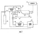
- FIG. 1A shows a schematic diagram of an illustrative apparatus that includes multiple radiation sources consistent with this invention
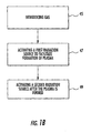
- FIG. 1B shows a flow chart for an illustrative method consistent with this invention
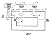
- FIG. 2 shows a simplified illustrative embodiment of a portion of a plasma system for adding a powder plasma catalyst to a plasma cavity for igniting, modulating, or sustaining a plasma in a cavity consistent with this invention
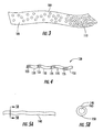
- FIG. 3 shows an illustrative plasma catalyst fiber with at least one component having a concentration gradient along its length consistent with this invention
- FIG. 4 shows an illustrative plasma catalyst fiber with multiple components at a ratio that varies along its length consistent with this invention
- FIG. 5A shows another illustrative plasma catalyst fiber that includes a core underlayer and a coating consistent with this invention
- FIG. 5B shows a cross-sectional view of the plasma catalyst fiber of FIG. 5A , taken from line 5B--5B of FIG. 5A , consistent with this invention
- FIG. 6 shows an illustrative embodiment of another portion of a plasma system including an elongated plasma catalyst that extends through an ignition port consistent with this invention
- FIG. 7 shows an illustrative embodiment of an elongated plasma catalyst that can be used in the system of FIG. 6 consistent with this invention
- FIG. 8 shows another illustrative embodiment of an elongated plasma catalyst that can be used in the system of FIG. 6 consistent with this invention.
- FIG. 9 shows an illustrative embodiment of a portion of a plasma system for directing ionizing radiation into a radiation chamber consistent with this invention.
- a radiation apparatus may include cavity 12. Further, in one embodiment, the radiation apparatus may further include a plasma catalyst located proximate to the cavity, which may cooperate with the radiation to cause the gas to form a plasma.
- This invention may further relate to methods and apparatus for initiating, modulating, and sustaining a plasma for a variety of applications, including heat-treating, synthesizing and depositing carbides, nitrides, borides, oxides, and other materials, doping, carburizing, nitriding, and carbonitriding, sintering, multi-part processing, joining, sintering, decrystallizing, making and operating furnaces, gas exhaust-treating, waste-treating, incinerating, scrubbing, ashing, growing carbon structures, generating hydrogen and other gases, forming electrodeless plasma jets, plasma processing in assembly lines, sterilizing, etc.
- a plasma furnace may include a chamber, a conduit for supplying gas to the chamber, a plurality of radiation sources arranged to radiate radiation into the chamber and a controller for delaying activation of all but a first of the plurality of radiation sources until after the first radiation source is activated.
- This invention can be used for controllably generating heat and for plasma-assisted processing to lower energy costs and increase heat-treatment efficiency and plasma-assisted manufacturing flexibility.
- a plasma catalyst for initiating, modulating, and sustaining a plasma.
- the catalyst can be passive or active.
- a passive plasma catalyst can include any object capable of inducing a plasma by deforming a local electric field (e.g., an electro-magnetic field) consistent with this invention without necessarily adding additional energy through the catalyst, such as by applying a voltage to create a spark.
- An active plasma catalyst may be any particle or high energy wave packet capable of transferring a sufficient amount of energy to a gaseous atom or ion to remove at least one electron from the gaseous atom or molecule, in the presence of electromagnetic radiation.
- FIG. 1A shows a schematic diagram of an illustrative radiation apparatus consistent with one aspect of the invention.
- the exemplary radiation apparatus may include cavity 12 formed in a vessel that may be positioned inside a microwave chamber (also known as applicator) 14.
- vessel 12 and microwave chamber 14 are the same, thereby eliminating the need for two separate components.
- the vessel in which cavity 12 is formed can include one or more radiation-transmissive insulating layers to improve its thermal insulation properties without significantly shielding cavity 12 from the radiation.
- the radiation apparatus may be configured as a plasma furnace.
- the radiation apparatus may also be used for initiating, modulating, and sustaining a plasma for a variety of other applications, including, for example, heat-treating, synthesizing and depositing carbides, nitrides, borides, oxides, and other materials, doping, carburizing, nitriding, and carbonitriding, sintering, multi-part processing, joining, sintering, decrystallizing, making and operating furnaces, gas exhaust-treating, waste-treating, incinerating, scrubbing, ashing, growing carbon structures, generating hydrogen and other gases, forming electrodeless plasma jets, plasma processing in assembly lines, sterilizing, etc.
- cavity 12 is formed in a vessel made of ceramic. Due to the extremely high temperatures that can be achieved with plasmas consistent with this invention, a ceramic capable of operating at about 3,000 degrees Fahrenheit can be used.
- the ceramic material can include, by weight, 29.8% silica, 68.2% alumina, 0.4% ferric oxide, 1% titania, 0.1 % lime, 0.1 % magnesia, 0.4% alkalies, which is sold under Model No. LW-30 by New Castle Refractories Company, of New Castle, Pennsylvania. It will be appreciated by those of ordinary skill in the art, however, that other materials, such as quartz, and those different from the one described above, can also be used consistent with the invention.
- a plasma may be formed in a partially open cavity inside a first brick and topped with a second brick.
- the cavity may have dimensions of about 2 inches by about 2 inches by about 1.5 inches.
- At least two holes may also be provided in the brick in communication with the cavity: one for viewing the plasma and at least one hole for providing the gas.
- the size of the cavity can depend on the desired plasma process being performed. Also, the cavity should at least be configured to prevent the plasma from rising/floating away from the primary processing region.
- Cavity 12 can be connected to one or more gas sources 24 (e.g., a source of argon, nitrogen, hydrogen, xenon, krypton) by line 20 and control valve 22, which may be powered by power supply 28.
- Line 20 may be tubing (e.g., between about 1/16 inch and about 1 ⁇ 4 inch, such as about 1/8").
- a vacuum pump can be connected to the chamber to remove any acidic fumes that may be generated during plasma processing. Also, any excess gas may escape the chamber via gas port 13 or similar additional gas ports.
- a radiation leak detector may be installed near source 26 and waveguide 30 and connected to a safety interlock system to automatically turn off the radiation (e.g., microwave) power supply if a leak above a predefined safety limit, such as one specified by the FCC and/or OSHA (e.g., 5 mW/cm 2 ), was detected.
- a safety interlock system to automatically turn off the radiation (e.g., microwave) power supply if a leak above a predefined safety limit, such as one specified by the FCC and/or OSHA (e.g., 5 mW/cm 2 ), was detected.
- the radiation apparatus may include radiation source 26 for directing radiation into the cavity.
- the radiation apparatus may further include radiation source 27 for directing radiation into the cavity.
- FIG. 1A depicts two radiation sources, it will be appreciated that the radiation apparatus can operate with two or more sources.
- source 26 may be configured to generate radiation that is cross-polarized relative to microwave radiation generated by source 27 and/or any other additional sources.
- Each of radiation sources 26 and 27 may be a magnetron, a klystron, a gyrotron, a traveling-wave tube amplifier/oscillator or any other device capable of generating radiation, such as microwave radiation.
- the frequency of the radiation is believed to be non-critical in many applications.
- radiation having any frequency less than about 333 GHz can be used consistent with this invention.
- frequencies, such as power line frequencies (about 50 Hz to about 60 Hz) can be used, although the pressure of the gas from which the plasma is formed may be lowered to assist with plasma ignition.
- any radio frequency or microwave frequency can be used consistent with this invention, including frequencies greater than about 100 kHz.
- the gas pressure for such relatively high frequencies need not be lowered to ignite, modulate, or sustain a plasma, thereby enabling many plasma-processes to occur over a broad range of pressures, including atmospheric pressure and above.
- Radiation source 26 which may be powered by electrical power supply 28, directs radiation energy into chamber 14 through one or more waveguides 30. It will be appreciated by those of ordinary skill in the art that source 26 can be connected directly to cavity 12 or chamber 14, thereby eliminating waveguide 30. The radiation energy entering cavity 12 is used to ignite a plasma within the cavity. This plasma can be substantially sustained and confined to the cavity by coupling additional radiation with the catalyst. Other radiation sources (such as 27) may similarly be directly connected to cavity 12 or chamber 14 or through one or more waveguides. Additionally, each one of them may be powered by power supply 28 or any other combination of power supplies may be used.
- Radiation energy, from radiation source 26, can be supplied through circulator 32 and tuner 34 (e.g., 3-stub tuner). Tuner 34 can be used to minimize the reflected power as a function of changing ignition or processing conditions, especially after the plasma has formed because microwave power, for example, will be strongly absorbed by the plasma. Similarly, radiation energy from radiation source 27 may be supplied through circulator 31 and tuner 33, although the use of circulators and tuners are optional.
- each of the radiation sources may be protectively separated from the chamber by an isolator (not shown).
- An isolator permits radiation to pass in one direction only, thereby protecting a source not only from reflected radiation, but also from radiation from other sources.
- reflected radiation can be minimized, especially during the early stages of plasma ignition.
- Detector 42 can develop output signals as a function of the temperature or any other monitorable condition associated with a work piece (not shown) within cavity 12 and provide the signals to controller 44. Dual temperature sensing and heating, as well as automated cooling and gas flow controls can also be used. Also, controller 44 may be programmed to sequentially activate source 27 after source 26 is activated. In another embodiment, controller 44 may delay activation of source 27 for a predetermined period following the activation of source 26. Sources 26 and 27 may also be delayed in a similar manner and may be triggered by any measurable event, if desired.
- detector 42 may provide an indication of microwave radiation absorption
- controller 44 may delay activation of one or more of the plurality of microwave radiation sources until after controller 44 receives a signal from detector 42 that a predetermined absorption threshold level has been reached.
- Detector 42 may be any device that detects one or more of heat, radiation absorption, radiation reflectance, radiation transmission, the existence of plasma, or any other phenomena signaling whether plasma formation has or has not occurred. Examples of such detectors include heat sensors, pyrometers, or any other sensor capable of detecting heat, temperature, radiation absorption, radiation reflectance, radiation transmission, the existence of plasma, or any other radiation related phenomena.
- Detector 42 can develop output signals as a function of the temperature or any other monitorable condition associated with a work piece (not shown) within cavity 12 and provide the signals to controller 44. Dual temperature sensing and heating, as well as automated cooling rate and gas flow controls can also be used. Controller 44 in turn can be used to control operation of power supply 28, which can have one output connected to source 26 as described above and another output connected to valve 22 to control gas flow into cavity 12. Although not shown, controller 44 or other similar controllers may be used to control operation of any other power supplies that may be used to supply power to the other radiation sources.
- detector 42 may provide an indication of radiation absorption by, for example, an object that is being processed.
- controller 44 may delay activation of subsequent sources until after controller 44 receives a signal from detector 42 that a predetermined absorption level has been reached.
- Controller 44 may also be configured to delay activation of at least one of the plurality of radiation sources for a predetermined period following activation of the first radiation source. Then, each of the remaining plurality of radiation sources may be successively activated at predetermined intervals, if desired. Controller 44 may also be configured to activate one or more additional radiation sources only after at least one of the first and second radiation sources is activated. Also, controller 44 may be configured to activate each of the plurality of additional radiation sources only after each of the first and the second radiation sources is activated.
- a plasma apparatus may include a plasma catalyst that is located proximate to a plasma cavity.
- the catalyst can cooperate with the radiation to cause a gas to form a plasma.
- proximate the cavity means either within the cavity or at a location sufficiently close to the cavity to effect the formation of the plasma.
- the location of radiation-transmissive cavity 12 in chamber 14 may not be critical if chamber 14 supports multiple modes, and especially when the modes are continually or periodically mixed.
- motor 36 can be connected to mode-mixer 38 for making the time-averaged radiation energy distribution substantially uniform throughout chamber 14.
- window 40 e.g., a quartz window
- temperature detector 42 e.g., an optical pyrometer
- the optical pyrometer output can increase from zero volts as the temperature rises to within the tracking range.
- the invention may be practiced, for example, by employing microwave sources at both 915 MHz and 2.45 GHz provided by Communications and Power Industries (CPI), although radiation having any frequency less than about 333 GHz can be used.
- the 2.45 GHz system may provide, for example, continuously variable microwave power from about 0.5 kilowatts to about 5.0 kilowatts.
- a 3-stub tuner may allow impedance matching for maximum power transfer and a dual directional coupler may be used to measure forward and reflected powers.
- optical pyrometers may be used for remote sensing of the sample temperature.
- radiation having any frequency less than about 333 GHz can be used consistent with this invention.
- frequencies such as power line frequencies (about 50 Hz to about 60 Hz)
- the pressure of the gas from which the plasma is formed may be lowered to assist with plasma ignition.
- any radio frequency or microwave frequency can be used consistent with this invention, including frequencies greater than about 100 kHz.
- the gas pressure for such relatively high frequencies need not be lowered to ignite, modulate, or sustain a plasma, thereby enabling many plasma-processes to occur at atmospheric pressures and above.
- the equipment may be computer controlled using LabView 6i software, which may provide real-time temperature monitoring and microwave power control. Noise may be reduced by using shift registers to generate sliding averages of suitable number of data points. Also, the number of stored data points in the array may be limited to improve speed and computational efficiency.
- the pyrometer may measure the temperature of a sensitive area of about 1 cm 2 , which may be used to calculate an average temperature. The pyrometer may sense radiant intensities at two wavelengths and fit those intensities using Planck's law to determine the temperature. It will be appreciated, however, that other devices and methods for monitoring and controlling temperature are also available and can be used consistent with this invention. Control software that can be used consistent with this invention is described, for example, in commonly owned, concurrently filed U.S. Patent Application No. 10/__,__ (Attorney Docket No. 1837.0033), which is hereby incorporated by reference in its entirety.
- Chamber 14 may have several glass-covered viewing ports with radiation shields and one quartz window for pyrometer access. Several ports for connection to a vacuum pump and a gas source may also be provided, although not necessarily used.
- the exemplary radiation apparatus may also include a closed-loop deionized water cooling system (not shown) with an external heat exchanger cooled by tap water.
- the deionized water may first cool the magnetron, then the load-dump in the circulator (used to protect the magnetron), and finally the microwave chamber through water channels welded on the outer surface of the chamber.
- FIG. 1 B shows a method employing at least a first and second radiation source, both arranged to direct radiation into a plasma formation region.
- the method may include introducing a gas (step 45) into a plasma-formation region. In one embodiment, this may be accomplished by turning on valve 22 of FIG. 1A .
- the plasma-formation region could be a cavity, which can be completely closed or partially open. For example, in certain applications, such as in plasma-assisted furnaces, the cavity could be entirely closed. See, for example, commonly owned, concurrently filed U.S. Patent Application No. 10/__,__ (Attorney Docket No. 1837.0020), which is fully incorporated herein by reference.
- the cavity must be open to some degree. In this way, the flow, type, and pressure of the flowing gas can be varied over time. This may be desirable because certain gases with lower ionization potentials, such as argon, are easier to ignite but may have other undesirable properties during subsequent plasma processing.
- the method may further include activating a first radiation source to facilitate formation of plasma in step 47.
- plasma formation may be facilitated using some kind of a plasma catalyst, such as a pointed metal tip, a spark generator, carbon, fiberous material, powderous material or any other catalyst capable of facilitating plasma ignition. Additional examples of plasma catalysts and their uses consistent with the present invention are more fully described below.
- the method may further include activating a second radiation source after the plasma is formed (step 49).
- radiation source 27 may be activated after the first radiation source is activated.
- the method may further include activating at least one additional radiation source after at least one of the first and second sources is activated. Further, the activation of the at least one additional radiation source may be delayed until after both the first and second sources are activated.
- the radiation sources may be, for example, a magnetron, a klystron, a gyrotron, a traveling-wave tube amplifier/oscillator, or any other source of radiation. Further, in one embodiment, the radiation sources may be cross-polarized.
- the method may include activating a plurality of radiation sources, wherein each of the plurality of microwave sources is successively activated at predetermined intervals.
- the plasma region may contain a plasma catalyst.
- the plasma catalyst consistent with this invention can include one or more different materials and may be either passive or active.
- a plasma catalyst can be used, among other things, to ignite, modulate, and/or sustain a plasma at a gas pressure that is less than, equal to, or greater than atmospheric pressure.
- One method of forming a plasma consistent with this invention can include subjecting a gas in a cavity to electromagnetic radiation having a frequency less than about 333 GHz in the presence of a passive plasma catalyst.
- a passive plasma catalyst consistent with this invention can include any object capable of inducing a plasma by deforming a local electric field (e.g., an electromagnetic field) consistent with this invention, without necessarily adding additional energy through the catalyst, such as by applying an electric voltage to create a spark.
- a passive plasma catalyst consistent with this invention can also be a nano-particle or a nano-tube.
- the term "nano-particle” can include any particle having a maximum physical dimension less than about 100 nm that is at least electrically semi-conductive.
- both single-walled and multi-walled carbon nanotubes, doped and undoped can be particularly effective for igniting plasmas consistent with this invention because of their exceptional electrical conductivity and elongated shape.
- the nanotubes can have any convenient length and can be a powder fixed to a substrate. If fixed, the nanotubes can be oriented randomly on the surface of the substrate or fixed to the substrate (e.g., at some predetermined orientation) while the plasma is ignited or sustained.
- a passive plasma catalyst can also be a powder consistent with this invention, and need not comprise nano-particles or nano-tubes. It can be formed, for example, from fibers, dust particles, flakes, sheets, etc.
- the catalyst can be suspended, at least temporarily, in a gas. By suspending the powder in the gas, the powder can be quickly dispersed throughout the cavity and more easily consumed, if desired.
- the powder catalyst can be carried into the cavity and at least temporarily suspended with a carrier gas.
- the carrier gas can be the same or different from the gas that forms the plasma.
- the powder can be added to the gas prior to being introduced to the cavity.
- radiation source 52 and radiation source 54 can supply radiation to radiation cavity 55, in which plasma cavity 60 is placed.
- Powder source 65 provides catalytic powder 70 into gas stream 75.
- powder 70 can be first added to cavity 60 in bulk (e.g., in a pile) and then distributed in the cavity in any number of ways, including flowing a gas through or over the bulk powder.
- the powder can be added to the gas for igniting, modulating, or sustaining a plasma by moving, conveying, drizzling, sprinkling, blowing, or otherwise, feeding the powder into or within the cavity.
- FIG. 2 shows only two radiation sources, additional radiation sources may be used.
- microwave source 54 may be activated and then, after a plasma is formed, microwave source 55 may be activated.
- a plasma was ignited in a cavity by placing a pile of carbon fiber powder in a copper pipe that extended into the cavity. Although sufficient radiation was directed into the cavity, the copper pipe shielded the powder from the radiation and no plasma ignition took place. However, once a carrier gas began flowing through the pipe, forcing the powder out of the pipe and into the cavity, and thereby subjecting the powder to the radiation, a plasma was nearly instantaneously ignited in the cavity. This permits a subsequent radiation source to be activated, which reduces the ramp-up time required to achieve, for example, very high temperature plasmas.
- a powder plasma catalyst consistent with this invention can be substantially non-combustible, thus it need not contain oxygen or burn in the presence of oxygen.
- the catalyst can include a metal, carbon, a carbon-based alloy, a carbon-based composite, an electrically conductive polymer, a conductive silicone elastomer, a polymer nanocomposite, an organic-inorganic composite, and any combination thereof.
- powder catalysts can be substantially uniformly distributed in the plasma cavity (e.g., when suspended in a gas), and plasma ignition can be precisely controlled within the cavity. Uniform ignition can be important in certain applications, including those applications requiring brief plasma exposures, such as in the form of one or more bursts. Still, a certain amount of time can be required for a powder catalyst to distribute itself throughout a cavity, especially in complicated, multi-chamber cavities. Therefore, consistent with another aspect of this invention, a powder catalyst can be introduced into the cavity through a plurality of ignition ports to more rapidly obtain a more uniform catalyst distribution therein (see below).
- a passive plasma catalyst consistent with this invention can include, for example, one or more microscopic or macroscopic fibers, sheets, needles, threads, strands, filaments, yarns, twines, shavings, slivers, chips, woven fabrics, tape, whiskers, or any combination thereof.
- the plasma catalyst can have at least one portion with one physical dimension substantially larger than another physical dimension.
- the ratio between at least two orthogonal dimensions should be at least about 1:2, but could be greater than about 1:5, or even greater than about 1:10.
- a passive plasma catalyst can include at least one portion of material that is relatively thin compared to its length.
- a bundle of catalysts e.g., fibers
- a section of tape having approximately thirty thousand strands of graphite fiber, each about 2-3 microns in diameter, was successfully used.
- the number of fibers in and the length of a bundle are not critical to igniting, modulating, or sustaining the plasma. For example, satisfactory results have been obtained using a section of graphite tape about one-quarter inch long.
- One type of carbon fiber that has been successfully used consistent with this invention is sold under the trademark Magnamite®, Model No. AS4C-GP3K, by the Hexcel Corporation, of Anderson, South Carolina.
- silicon-carbide fibers have been successfully used.
- a passive plasma catalyst consistent with another aspect of this invention can include one or more portions that are, for example, substantially spherical, annular, pyramidal, cubic, planar, cylindrical, rectangular or elongated.
- the passive plasma catalysts discussed above include at least one material that is at least electrically semi-conductive.
- the material can be highly conductive.
- a passive plasma catalyst consistent with this invention can include a metal, an inorganic material, carbon, a carbon-based alloy, a carbon-based composite, an electrically conductive polymer, a conductive silicone elastomer, a polymer nanocomposite, an organic-inorganic composite, or any combination thereof.
- Some of the possible inorganic materials that can be included in the plasma catalyst include carbon, silicon carbide, molybdenum, platinum, tantalum, tungsten, carbon nitride, and aluminum, although other electrically conductive inorganic materials are believed to work just as well.
- a passive plasma catalyst consistent with this invention can include one or more additives (which need not be electrically conductive).
- the additive can include any material that a user wishes to add to the plasma.
- one or more dopants can be added to the plasma through the catalyst. See, e.g., commonly owned, concurrently filed U.S. Patent Application No. 10/__,__ (Attorney Docket No. 1837.0026), which is hereby incorporated by reference in its entirety.
- the catalyst can include the dopant itself, or it can include a precursor material that, upon decomposition, can form the dopant.
- the plasma catalyst can include one or more additives and one or more electrically conductive materials in any desirable ratio, depending on the ultimate desired composition of the plasma and the process using the plasma.
- the ratio of the electrically conductive components to the additives in a passive plasma catalyst can vary over time while being consumed.
- the plasma catalyst could desirably include a relatively large percentage of electrically conductive components to improve the ignition conditions.
- the catalyst could include a relatively large percentage of additives. It will be appreciated by those of ordinary skill in the art that the component ratio of the plasma catalyst used to ignite and sustain the plasma could be the same.
- a predetermined ratio profile can be used to simplify many plasma processes.
- the components within the plasma are added as necessary, but such addition normally requires programmable equipment to add the components according to a predetermined schedule.
- the ratio of components in the catalyst can be varied, and thus the ratio of components in the plasma itself can be automatically varied. That is, the ratio of components in the plasma at any particular time can depend on which of the catalyst portions is currently being consumed by the plasma.
- the catalyst component ratio can be different at different locations within the catalyst.
- the current ratio of components in a plasma can depend on the portions of the catalyst currently and/or previously consumed, especially when the flow rate of a gas passing through the plasma chamber is relatively slow.
- a passive plasma catalyst consistent with this invention can be homogeneous, inhomogeneous, or graded.
- the plasma catalyst component ratio can vary continuously or discontinuously throughout the catalyst. For example, in FIG. 3 , the ratio can vary smoothly forming a gradient along a length of catalyst 100.
- Catalyst 100 can include a strand of material that includes a relatively low concentration of a component at section 105 and a continuously increasing concentration toward section 110.
- the ratio can vary discontinuously in each portion of catalyst 120, which includes, for example, alternating sections 125 and 130 having different concentrations. It will be appreciated that catalyst 120 can have more than two section types. Thus, the catalytic component ratio being consumed by the plasma can vary in any predetermined fashion. In one embodiment, when the plasma is monitored and a particular additive is detected, further processing can be automatically commenced or terminated.
- an automated system can include a device by which a consumable plasma catalyst is mechanically inserted before and/or during plasma igniting, modulating, and/or sustaining.
- a passive plasma catalyst consistent with this invention can also be coated.
- a catalyst can include a substantially non-electrically conductive coating deposited on the surface of a substantially electrically conductive material.
- the catalyst can include a substantially electrically conductive coating deposited on the surface of a substantially electrically non-conductive material.
- FIGS. 5A and 5B show fiber 140, which includes underlayer 145 and coating 150.
- a plasma catalyst including a carbon core is coated with nickel to prevent oxidation of the carbon.
- a single plasma catalyst can also include multiple coatings. If the coatings are consumed during contact with the plasma, the coatings could be introduced into the plasma sequentially, from the outer coating to the innermost coating, thereby creating a time-release mechanism.
- a coated plasma catalyst can include any number of materials, as long as a portion of the catalyst is at least electrically semi-conductive.
- a plasma catalyst can be located entirely within a radiation cavity to substantially reduce or prevent radiation energy leakage.
- the plasma catalyst does not electrically or magnetically couple with the vessel containing the cavity or to any electrically conductive object outside the cavity. This prevents sparking at the ignition port and prevents radiation from leaking outside the cavity during the ignition and possibly later if the plasma is sustained.
- the catalyst can be located at a tip of a substantially electrically non-conductive extender that extends through an ignition port.
- FIG. 6 shows radiation chamber 160 in which plasma cavity 165 is placed.
- Plasma catalyst 170 is elongated and extends through ignition port 175.
- catalyst 170 can include electrically conductive distal portion 180 (which is placed in chamber 160) and electrically non-conductive portion 185 (which is placed substantially outside chamber 160). This configuration prevents an electrical connection (e.g., sparking) between distal portion 180 and chamber 160.
- the catalyst can be formed from a plurality of electrically conductive segments 190 separated by and mechanically connected to a plurality of electrically non-conductive segments 195.
- the catalyst can extend through the ignition port between a point inside the cavity and another point outside the cavity, but the electrically discontinuous profile significantly prevents sparking and energy leakage.
- Another method of forming a plasma consistent with this invention includes subjecting a gas in a cavity to electromagnetic radiation having a frequency less than about 333 GHz in the presence of an active plasma catalyst, which generates or includes at least one ionizing particle.
- An active plasma catalyst consistent with this invention can be any particle or high energy wave packet capable of transferring a sufficient amount of energy to a gaseous atom or molecule to remove at least one electron from the gaseous atom or molecule in the presence of electromagnetic radiation.
- the ionizing particles can be directed into the cavity in the form of a focused or collimated beam, or they may be sprayed, spewed, sputtered, or otherwise introduced.
- FIG. 9 shows radiation source 200 and radiation source 202 for directing radiation into radiation chamber 205.
- Plasma cavity 210 is positioned inside of chamber 205 and may permit a gas to flow therethrough via ports 215 and 216.
- Source 220 directs ionizing particles 225 into cavity 210.
- Source 220 can be protected, for example, by a metallic screen which allows the ionizing particles to pass through but shields source 220 from radiation. If necessary, source 220 can be water-cooled.
- radiation source 200 may be activated and then, after a plasma is formed, radiation source 202 may be activated. Alternatively, radiation source 202 may be activated after a predetermined interval.
- Examples of ionizing particles consistent with this invention can include x-ray particles, gamma ray particles, alpha particles, beta particles, neutrons, protons, and any combination thereof.
- an ionizing particle catalyst can be charged (e.g., an ion from an ion source) or uncharged and can be the product of a radioactive fission process.
- the vessel in which the plasma cavity is formed could be entirely or partially transmissive to the ionizing particle catalyst.
- the source can direct the fission products through the vessel to ignite the plasma.
- the radioactive fission source can be located inside the radiation chamber to substantially prevent the fission products (i.e., the ionizing particle catalyst) from creating a safety hazard.
- the ionizing particle can be a free electron, but it need not be emitted in a radioactive decay process.
- the electron can be introduced into the cavity by energizing the electron source (such as a metal), such that the electrons have sufficient energy to escape from the source.
- the electron source can be located inside the cavity, adjacent the cavity, or even in the cavity wall. It will be appreciated by those of ordinary skill in the art that the any combination of electron sources is possible.
- a common way to produce electrons is to heat a metal, and these electrons can be further accelerated by applying an electric field.
- free energetic protons can also be used to catalyze a plasma.
- a free proton can be generated by ionizing hydrogen and, optionally, accelerated with an electric field.
- a radiation waveguide, cavity, or chamber can support or facilitate propagation of at least one electromagnetic radiation mode.
- the term "mode" refers to a particular pattern of any standing or propagating electromagnetic wave that satisfies Maxwell's equations and the applicable boundary conditions (e.g., of the cavity).
- the mode can be any one of the various possible patterns of propagating or standing electromagnetic fields.
- Each mode is characterized by its frequency and polarization of the electric field and/or the magnetic field vectors.
- the electromagnetic field pattern of a mode depends on the frequency, refractive indices or dielectric constants, and waveguide or cavity geometry.
- a transverse electric (TE) mode is one whose electric field vector is normal to the direction of propagation.
- a transverse magnetic (TM) mode is one whose magnetic field vector is normal to the direction of propagation.
- a transverse electric and magnetic (TEM) mode is one whose electric and magnetic field vectors are both normal to the direction of propagation.
- a hollow metallic waveguide does not typically support a normal TEM mode of radiation propagation. Even though radiation appears to travel along the length of a waveguide, it may do so only by reflecting off the inner walls of the waveguide at some angle. Hence, depending upon the propagation mode, the radiation (e.g., microwave) may have either some electric field component or some magnetic field component along the axis of the waveguide (often referred to as the z-axis).
- the actual field distribution inside a cavity or waveguide is a superposition of the modes therein.
- Each of the modes can be identified with one or more subscripts (e.g., TE 10 ("tee ee one zero").
- the subscripts normally specify how many "half waves" at the guide wavelength are contained in the x and y directions. It will be appreciated by those skilled in the art that the guide wavelength can be different from the free space wavelength because radiation propagates inside the waveguide by reflecting at some angle from the inner walls of the waveguide.
- a third subscript can be added to define the number of half waves in the standing wave pattern along the z-axis.
- the size of the waveguide can be selected to be small enough so that it can support a single propagation mode.
- the system is called a single-mode system (i.e., a single-mode applicator).
- the TE 10 mode is usually dominant in a rectangular single-mode waveguide.
- the waveguide or applicator can sometimes support additional higher order modes forming a multi-mode system.
- the system is often referred to as highly moded.
- a simple, single-mode system has a field distribution that includes at least one maximum and/or minimum.
- the magnitude of a maximum largely depends on the amount of radiation supplied to the system.
- the field distribution of a single mode system is strongly varying and substantially nonuniform.
- a multi-mode cavity can support several propagation modes simultaneously, which, when superimposed, results in a complex field distribution pattern. In such a pattern, the fields tend to spatially smear and, thus, the field distribution usually does not show the same types of strong minima and maxima field values within the cavity.
- a mode-mixer can be used to "stir" or "redistribute” modes (e.g., by mechanical movement of a radiation reflector). This redistribution desirably provides a more uniform time-averaged field distribution within the cavity.
- a multi-mode cavity consistent with this invention can support at least two modes, and may support many more than two modes. Each mode has a maximum electric field vector. Although there may be two or more modes, one mode may be dominant and has a maximum electric field vector magnitude that is larger than the other modes.
- a multi-mode cavity may be any cavity in which the ratio between the first and second mode magnitudes is less than about 1:10, or less than about 1:5, or even less than about 1:2. It will be appreciated by those of ordinary skill in the art that the smaller the ratio, the more distributed the electric field energy between the modes, and hence the more distributed the radiation energy is in the cavity.
- the distribution of plasma within a processing cavity may strongly depend on the distribution of the applied radiation. For example, in a pure single mode system, there may only be a single location at which the electric field is a maximum. Therefore, a strong plasma may only form at that single location. In many applications, such a strongly localized plasma could undesirably lead to nonuniform plasma treatment or heating (i.e., localized overheating and underheating).
- the cavity in which the plasma is formed can be completely closed or partially open.
- the cavity could be entirely closed. See, for example, commonly owned, concurrently filed U.S. Patent Application No. 10/__,__ (Attorney Docket No. 1837.0020), which is fully incorporated herein by reference.
- a cavity containing a uniform plasma is desirable.
- microwave radiation can have a relatively long wavelength (e.g., several tens of centimeters)
- obtaining a uniform distribution can be difficult to achieve.
- the radiation modes in a multi-mode cavity can be mixed, or redistributed, over a period of time. Because the field distribution within the cavity must satisfy all of the boundary conditions set by the inner surface of the cavity, those field distributions can be changed by changing the position of any portion of that inner surface.
- a movable reflective surface can be located inside the radiation cavity.
- the shape and motion of the reflective surface should, when combined, change the inner surface of the cavity during motion.
- an "L" shaped metallic object i.e., "mode-mixer”
- mode-mixer when rotated about any axis will change the location or the orientation of the reflective surfaces in the cavity and therefore change the radiation distribution therein.
- Any other asymmetrically shaped object can also be used (when rotated), but symmetrically shaped objects can also work, as long as the relative motion (e.g., rotation, translation, or a combination of both) causes some change in the location or the orientation of the reflective surfaces.
- a mode-mixer can be a cylinder that is rotatable about an axis that is not the cylinder's longitudinal axis.
- Each mode of a multi-mode cavity may have at least one maximum electric field vector, but each of these vectors could occur periodically across the inner dimension of the cavity. Normally, these maxima are fixed, assuming that the frequency of the radiation does not change. However, by moving a mode-mixer such that it interacts with the radiation, it is possible to move the positions of the maxima.
- mode-mixer 38 can be used to optimize the field distribution within cavity 14 such that the plasma ignition conditions and/or the plasma sustaining conditions are optimized.
- the position of the mode-mixer can be changed to move the position of the maxima for a uniform time-averaged plasma process (e.g., heating).
- mode-mixing can be useful during plasma ignition.
- an electrically conductive fiber is used as a plasma catalyst, it is known that the fiber's orientation can strongly affect the minimum plasma-ignition conditions. It has been reported, for example, that when such a fiber is oriented at an angle that is greater than 60° to the electric field, the catalyst does little to improve, or relax, these conditions. By moving a reflective surface either in or near the cavity, however, the electric field distribution can be significantly changed.
- Mode-mixing can also be achieved by launching the radiation into the applicator chamber through, for example, a rotating waveguide joint that can be mounted inside the applicator chamber.
- the rotary joint can be mechanically moved (e.g., rotated) to effectively launch the radiation in different directions in the radiation chamber.
- a changing field pattern can be generated inside the applicator chamber.
- Mode-mixing can also be achieved by launching radiation in the radiation chamber through a flexible waveguide.
- the waveguide can be mounted inside the chamber.
- the waveguide can extend into the chamber.
- the position of the end portion of the flexible waveguide can be continually or periodically moved (e.g., bent) in any suitable manner to launch the radiation (e.g., microwave radiation) into the chamber at different directions and/or locations.
- This movement can also result in mode-mixing and facilitate more uniform plasma processing (e.g., heating) on a time-averaged basis. Alternatively, this movement can be used to optimize the location of a plasma for ignition or other plasma-assisted process.
- the flexible waveguide is rectangular, a simple twisting of the open end of the waveguide will rotate the orientation of the electric and the magnetic field vectors in the radiation inside the applicator chamber. Then, a periodic twisting of the waveguide can result in mode-mixing as well as rotating the electric field, which can be used to assist ignition, modulation, or sustaining of a plasma.
- mode-mixing can be continuous, periodic, or preprogrammed.
- mode-mixing can be useful during subsequent plasma processing to reduce or create (e.g., tune) "hot spots" in the chamber.
- a microwave cavity only supports a small number of modes (e.g., less than 5)
- one or more localized electric field maxima can lead to "hot spots" (e.g., within cavity 12).
- these hot spots could be configured to coincide with one or more separate, but simultaneous, plasma ignitions or processing events.
- the plasma catalyst can be located at one or more of those ignition or subsequent processing positions.
- a plasma can be ignited using multiple plasma catalysts at different locations.
- multiple fibers can be used to ignite the plasma at different points within the cavity.
- Such multi-point ignition can be especially beneficial when a uniform plasma ignition is desired. For example, when a plasma is modulated at a high frequency (i.e., tens of Hertz and higher), or ignited in a relatively large volume, or both, substantially uniform instantaneous striking and restriking of the plasma can be improved.
- plasma catalysts when plasma catalysts are used at multiple points, they can be used to sequentially ignite a plasma at different locations within a plasma chamber by selectively introducing the catalyst at those different locations. In this way, a plasma ignition gradient can be controllably formed within the cavity, if desired.
- each powder particle may have the effect of being placed at a different physical location within the cavity, thereby improving ignition uniformity within the cavity.
Abstract
Description
- Priority is claimed to
U.S. Provisional Patent Application No. 60/378,693, filed May 8, 2002 60/430,677, filed December 4, 2002 60/435,278, filed December 23, 2002 - The invention relates to methods and apparatus for plasma-assisted processing, and in particular to using multiple electromagnetic radiation sources in combination.
- It is known that a single microwave radiation source can be used to generate a plasma by subjecting a gas to a sufficient amount of microwave radiation. A single microwave energy source can be damaged, however, when one source directs microwave energy into a plasma chamber that reflects the energy back toward the same source. This can be especially problematic when there is no strong microwave absorber in the cavity, such as when a plasma is not yet formed. Also, multiple microwave energy sources are particularly susceptible to damage when combined to ignite or sustain a plasma. For example, a first source can be damaged when it directs microwave energy into a chamber because that energy could be directed into another simultaneously connected radiation source.
- It is also known that plasma ignition is usually easier at gas pressures substantially less than atmospheric pressure. However, vacuum equipment, which is required to lower the gas pressure, can be expensive, as well as slow and energy-consuming. Moreover, the use of such equipment can limit manufacturing flexibility. Document
US 6248206 discloses an example of a gas submitted to two consecutive radiation sources. - Consistent with the present invention, apparatus and methods using multiple radiation sources (e.g., microwave radiation sources) are provided. Plasmas formed from gases at pressures at about one atmosphere or higher can strongly absorb microwave radiation. Strong absorption can be used to reduce the possibility of damage to a particular source by its own radiation that may be reflected back or radiation from other sources. Consequently, high power plasma-assisted processes can be carried out using multiple (e.g., low power) sources coupled to the same plasma.
- In one embodiment, a radiation apparatus may include a cavity. The radiation apparatus can also include a first high-frequency radiation source and a second high-frequency radiation source for directing radiation into the cavity. The radiation apparatus may include a controller for sequentially activating the second radiation source after the first radiation source is activated.
- In another embodiment consistent with this invention, a plasma furnace may include a chamber, a conduit for supplying gas to the chamber, a plurality of radiation sources arranged to radiate radiation into the chamber, and a controller for delaying activation of all but a first of the plurality of radiation sources until after the first radiation source is activated. A radiation apparatus and a plasma furnace consistent with this invention may include a plasma catalyst located proximate to the cavity. The plasma catalyst can cooperate with the microwave radiation in the presence of a gas to form a plasma. The catalyst can be passive or active. A passive plasma catalyst can include any object capable inducing a plasma by deforming a local electric field (e.g., an electromagnetic field) consistent with this invention, without necessarily adding additional energy. An active plasma catalyst, on the other hand, is any particle or high energy wave packet capable of transferring a sufficient amount of energy to a gaseous atom or molecule to remove at least one electron from the gaseous atom or molecule in the presence of electromagnetic radiation. In both cases, a plasma catalyst can improve, or relax, the environmental conditions required to ignite a plasma.
- In another embodiment consistent with this invention, a method for forming a plasma is provided. The method can include employing at least first and second radiation sources arranged to direct radiation into a processing or heating region. The method can include introducing gas into the region, activating the first radiation source to facilitate formation of plasma in the heating region, and activating the second radiation source after the plasma is formed.
- In yet another embodiment not part of this invention, additional methods and apparatus are provided for forming a plasma using a dual-cavity system. The system can include a first ignition cavity and a second cavity in fluid communication with each other. The method can include (i) subjecting a gas in the first ignition cavity to electromagnetic radiation having a frequency less than about 333 GHz, such that the plasma in the first cavity causes a second plasma to form in the second cavity, and (ii) sustaining the second plasma in the second cavity by subjecting it to additional electromagnetic radiation.
- Additional plasma catalysts, and methods and apparatus for igniting, modulating, and sustaining a plasma consistent with this invention are provided.
- Further aspects of the invention will be apparent upon consideration of the following detailed description, taken in conjunction with the accompanying drawings, in which like reference characters refer to like parts throughout, and in which:
-
FIG. 1A shows a schematic diagram of an illustrative apparatus that includes multiple radiation sources consistent with this invention; -
FIG. 1B shows a flow chart for an illustrative method consistent with this invention; -
FIG. 2 shows a simplified illustrative embodiment of a portion of a plasma system for adding a powder plasma catalyst to a plasma cavity for igniting, modulating, or sustaining a plasma in a cavity consistent with this invention; -
FIG. 3 shows an illustrative plasma catalyst fiber with at least one component having a concentration gradient along its length consistent with this invention; -
FIG. 4 shows an illustrative plasma catalyst fiber with multiple components at a ratio that varies along its length consistent with this invention; -
FIG. 5A shows another illustrative plasma catalyst fiber that includes a core underlayer and a coating consistent with this invention; -
FIG. 5B shows a cross-sectional view of the plasma catalyst fiber ofFIG. 5A , taken fromline 5B--5B ofFIG. 5A , consistent with this invention; -
FIG. 6 shows an illustrative embodiment of another portion of a plasma system including an elongated plasma catalyst that extends through an ignition port consistent with this invention; -
FIG. 7 shows an illustrative embodiment of an elongated plasma catalyst that can be used in the system ofFIG. 6 consistent with this invention; -
FIG. 8 shows another illustrative embodiment of an elongated plasma catalyst that can be used in the system ofFIG. 6 consistent with this invention; and -
FIG. 9 shows an illustrative embodiment of a portion of a plasma system for directing ionizing radiation into a radiation chamber consistent with this invention. - Consistent with the present invention, plasma apparatus and methods that use multiple radiation sources are provided. In one embodiment, as shown in
FIG. 1A , a radiation apparatus may includecavity 12. Further, in one embodiment, the radiation apparatus may further include a plasma catalyst located proximate to the cavity, which may cooperate with the radiation to cause the gas to form a plasma. - This invention may further relate to methods and apparatus for initiating, modulating, and sustaining a plasma for a variety of applications, including heat-treating, synthesizing and depositing carbides, nitrides, borides, oxides, and other materials, doping, carburizing, nitriding, and carbonitriding, sintering, multi-part processing, joining, sintering, decrystallizing, making and operating furnaces, gas exhaust-treating, waste-treating, incinerating, scrubbing, ashing, growing carbon structures, generating hydrogen and other gases, forming electrodeless plasma jets, plasma processing in assembly lines, sterilizing, etc.
- In another embodiment, a plasma furnace is provided that may include a chamber, a conduit for supplying gas to the chamber, a plurality of radiation sources arranged to radiate radiation into the chamber and a controller for delaying activation of all but a first of the plurality of radiation sources until after the first radiation source is activated. Each of these components is explained more fully below.
- This invention can be used for controllably generating heat and for plasma-assisted processing to lower energy costs and increase heat-treatment efficiency and plasma-assisted manufacturing flexibility.
- Therefore, a plasma catalyst for initiating, modulating, and sustaining a plasma is provided. The catalyst can be passive or active. A passive plasma catalyst can include any object capable of inducing a plasma by deforming a local electric field (e.g., an electro-magnetic field) consistent with this invention without necessarily adding additional energy through the catalyst, such as by applying a voltage to create a spark. An active plasma catalyst, on the other hand, may be any particle or high energy wave packet capable of transferring a sufficient amount of energy to a gaseous atom or ion to remove at least one electron from the gaseous atom or molecule, in the presence of electromagnetic radiation.
- The following commonly owned, concurrently filed U.S. patent applications are hereby incorporated by reference in their entireties: U.S. Patent Application No. 10/__,__ (Atty. Docket No. 1837.0008), No. 10/__,__ (Atty. Docket No. 1837.0009), No. 10/__,__ (Atty. Docket No. 1837.0010), No. 10/__,__ (Atty. Docket No. 1837.0011), No. 10/__,__ (Atty. Docket No. 1837.0012), No. 10/__,__ (Atty. Docket No. 1837.0013), No. 10/__,__ (Atty. Docket No. 1837.0015), No. 10/__,__ (Atty. Docket No. 1837.0016), No. 10/__,__ (Atty. Docket No. 1837.0017), No. 10/__,__ (Atty. Docket No. 1837.0020), No. 10/__,__ (Atty. Docket No. 1837.0021), No. 10/__,__ (Atty. Docket No. 1837.0023), No. 10/__,__ (Atty. Docket No. 1837.0024), No. 10/__,__ (Atty. Docket No. 1837.0025), No. 10/__,__ (Atty. Docket No. 1837.0026), No. 10/__,__ (Atty. Docket No. 1837.0027), No. 10/__,__ (Atty. Docket No. 1837.0028), No. 10/__,__ (Atty. Docket No. 1837.0029), No. 10/__,__ (Atty. Docket No. 1837.0030), No. 10/__,__ (Atty. Docket No. 1837.0032), and No. 10/__,__ (Atty. Docket No. 1837.0033).
- Illustrative Plasma System
-
FIG. 1A shows a schematic diagram of an illustrative radiation apparatus consistent with one aspect of the invention. The exemplary radiation apparatus may includecavity 12 formed in a vessel that may be positioned inside a microwave chamber (also known as applicator) 14. In another embodiment (not shown),vessel 12 andmicrowave chamber 14 are the same, thereby eliminating the need for two separate components. The vessel in whichcavity 12 is formed can include one or more radiation-transmissive insulating layers to improve its thermal insulation properties without significantly shieldingcavity 12 from the radiation. - In one embodiment, the radiation apparatus may be configured as a plasma furnace. One skilled in the art will appreciate that the radiation apparatus may also be used for initiating, modulating, and sustaining a plasma for a variety of other applications, including, for example, heat-treating, synthesizing and depositing carbides, nitrides, borides, oxides, and other materials, doping, carburizing, nitriding, and carbonitriding, sintering, multi-part processing, joining, sintering, decrystallizing, making and operating furnaces, gas exhaust-treating, waste-treating, incinerating, scrubbing, ashing, growing carbon structures, generating hydrogen and other gases, forming electrodeless plasma jets, plasma processing in assembly lines, sterilizing, etc.
- In one embodiment,
cavity 12 is formed in a vessel made of ceramic. Due to the extremely high temperatures that can be achieved with plasmas consistent with this invention, a ceramic capable of operating at about 3,000 degrees Fahrenheit can be used. The ceramic material can include, by weight, 29.8% silica, 68.2% alumina, 0.4% ferric oxide, 1% titania, 0.1 % lime, 0.1 % magnesia, 0.4% alkalies, which is sold under Model No. LW-30 by New Castle Refractories Company, of New Castle, Pennsylvania. It will be appreciated by those of ordinary skill in the art, however, that other materials, such as quartz, and those different from the one described above, can also be used consistent with the invention. - A plasma may be formed in a partially open cavity inside a first brick and topped with a second brick. The cavity may have dimensions of about 2 inches by about 2 inches by about 1.5 inches. At least two holes may also be provided in the brick in communication with the cavity: one for viewing the plasma and at least one hole for providing the gas. The size of the cavity can depend on the desired plasma process being performed. Also, the cavity should at least be configured to prevent the plasma from rising/floating away from the primary processing region.
-
Cavity 12 can be connected to one or more gas sources 24 (e.g., a source of argon, nitrogen, hydrogen, xenon, krypton) byline 20 andcontrol valve 22, which may be powered bypower supply 28.Line 20 may be tubing (e.g., between about 1/16 inch and about ¼ inch, such as about 1/8"). Also, if desired, a vacuum pump can be connected to the chamber to remove any acidic fumes that may be generated during plasma processing. Also, any excess gas may escape the chamber viagas port 13 or similar additional gas ports. - A radiation leak detector (not shown) may be installed near
source 26 andwaveguide 30 and connected to a safety interlock system to automatically turn off the radiation (e.g., microwave) power supply if a leak above a predefined safety limit, such as one specified by the FCC and/or OSHA (e.g., 5 mW/cm2), was detected. - In one embodiment, the radiation apparatus may include
radiation source 26 for directing radiation into the cavity. The radiation apparatus may further includeradiation source 27 for directing radiation into the cavity. AlthoughFIG. 1A depicts two radiation sources, it will be appreciated that the radiation apparatus can operate with two or more sources. - In one embodiment,
source 26 may be configured to generate radiation that is cross-polarized relative to microwave radiation generated bysource 27 and/or any other additional sources. - Each of
radiation sources -
Radiation source 26, which may be powered byelectrical power supply 28, directs radiation energy intochamber 14 through one ormore waveguides 30. It will be appreciated by those of ordinary skill in the art that source 26 can be connected directly tocavity 12 orchamber 14, thereby eliminatingwaveguide 30. The radiationenergy entering cavity 12 is used to ignite a plasma within the cavity. This plasma can be substantially sustained and confined to the cavity by coupling additional radiation with the catalyst. Other radiation sources (such as 27) may similarly be directly connected tocavity 12 orchamber 14 or through one or more waveguides. Additionally, each one of them may be powered bypower supply 28 or any other combination of power supplies may be used. - Radiation energy, from
radiation source 26, can be supplied throughcirculator 32 and tuner 34 (e.g., 3-stub tuner).Tuner 34 can be used to minimize the reflected power as a function of changing ignition or processing conditions, especially after the plasma has formed because microwave power, for example, will be strongly absorbed by the plasma. Similarly, radiation energy fromradiation source 27 may be supplied throughcirculator 31 andtuner 33, although the use of circulators and tuners are optional. - In one embodiment, each of the radiation sources may be protectively separated from the chamber by an isolator (not shown). An isolator permits radiation to pass in one direction only, thereby protecting a source not only from reflected radiation, but also from radiation from other sources. However, consistent with this invention, reflected radiation can be minimized, especially during the early stages of plasma ignition.
-
Detector 42 can develop output signals as a function of the temperature or any other monitorable condition associated with a work piece (not shown) withincavity 12 and provide the signals tocontroller 44. Dual temperature sensing and heating, as well as automated cooling and gas flow controls can also be used. Also,controller 44 may be programmed to sequentially activatesource 27 aftersource 26 is activated. In another embodiment,controller 44 may delay activation ofsource 27 for a predetermined period following the activation ofsource 26.Sources - In one embodiment,
detector 42 may provide an indication of microwave radiation absorption, andcontroller 44 may delay activation of one or more of the plurality of microwave radiation sources until aftercontroller 44 receives a signal fromdetector 42 that a predetermined absorption threshold level has been reached. -
Detector 42 may be any device that detects one or more of heat, radiation absorption, radiation reflectance, radiation transmission, the existence of plasma, or any other phenomena signaling whether plasma formation has or has not occurred. Examples of such detectors include heat sensors, pyrometers, or any other sensor capable of detecting heat, temperature, radiation absorption, radiation reflectance, radiation transmission, the existence of plasma, or any other radiation related phenomena. -
Detector 42 can develop output signals as a function of the temperature or any other monitorable condition associated with a work piece (not shown) withincavity 12 and provide the signals tocontroller 44. Dual temperature sensing and heating, as well as automated cooling rate and gas flow controls can also be used.Controller 44 in turn can be used to control operation ofpower supply 28, which can have one output connected to source 26 as described above and another output connected tovalve 22 to control gas flow intocavity 12. Although not shown,controller 44 or other similar controllers may be used to control operation of any other power supplies that may be used to supply power to the other radiation sources. - In another embodiment,
detector 42 may provide an indication of radiation absorption by, for example, an object that is being processed. In this case,controller 44 may delay activation of subsequent sources until aftercontroller 44 receives a signal fromdetector 42 that a predetermined absorption level has been reached. -
Controller 44 may also be configured to delay activation of at least one of the plurality of radiation sources for a predetermined period following activation of the first radiation source. Then, each of the remaining plurality of radiation sources may be successively activated at predetermined intervals, if desired.Controller 44 may also be configured to activate one or more additional radiation sources only after at least one of the first and second radiation sources is activated. Also,controller 44 may be configured to activate each of the plurality of additional radiation sources only after each of the first and the second radiation sources is activated. - Consistent with this invention, a plasma apparatus may include a plasma catalyst that is located proximate to a plasma cavity. The catalyst can cooperate with the radiation to cause a gas to form a plasma. Also, as used herein, the phrase "proximate the cavity" means either within the cavity or at a location sufficiently close to the cavity to effect the formation of the plasma.
- As explained more fully below, the location of radiation-
transmissive cavity 12 inchamber 14 may not be critical ifchamber 14 supports multiple modes, and especially when the modes are continually or periodically mixed. As also explained more fully below,motor 36 can be connected to mode-mixer 38 for making the time-averaged radiation energy distribution substantially uniform throughoutchamber 14. Furthermore, window 40 (e.g., a quartz window) can be disposed in one wall ofchamber 14 adjacent tocavity 12, permitting temperature detector 42 (e.g., an optical pyrometer) to be used to view a process insidecavity 12. In one embodiment, the optical pyrometer output can increase from zero volts as the temperature rises to within the tracking range. - The invention may be practiced, for example, by employing microwave sources at both 915 MHz and 2.45 GHz provided by Communications and Power Industries (CPI), although radiation having any frequency less than about 333 GHz can be used. The 2.45 GHz system may provide, for example, continuously variable microwave power from about 0.5 kilowatts to about 5.0 kilowatts. A 3-stub tuner may allow impedance matching for maximum power transfer and a dual directional coupler may be used to measure forward and reflected powers. Also, optical pyrometers may be used for remote sensing of the sample temperature.
- As mentioned above, radiation having any frequency less than about 333 GHz can be used consistent with this invention. For example, frequencies, such as power line frequencies (about 50 Hz to about 60 Hz), can be used, although the pressure of the gas from which the plasma is formed may be lowered to assist with plasma ignition. Also, any radio frequency or microwave frequency can be used consistent with this invention, including frequencies greater than about 100 kHz. In most cases, the gas pressure for such relatively high frequencies need not be lowered to ignite, modulate, or sustain a plasma, thereby enabling many plasma-processes to occur at atmospheric pressures and above.
- The equipment may be computer controlled using LabView 6i software, which may provide real-time temperature monitoring and microwave power control. Noise may be reduced by using shift registers to generate sliding averages of suitable number of data points. Also, the number of stored data points in the array may be limited to improve speed and computational efficiency. The pyrometer may measure the temperature of a sensitive area of about 1 cm2, which may be used to calculate an average temperature. The pyrometer may sense radiant intensities at two wavelengths and fit those intensities using Planck's law to determine the temperature. It will be appreciated, however, that other devices and methods for monitoring and controlling temperature are also available and can be used consistent with this invention. Control software that can be used consistent with this invention is described, for example, in commonly owned, concurrently filed U.S. Patent Application No. 10/__,__ (Attorney Docket No. 1837.0033), which is hereby incorporated by reference in its entirety.
-
Chamber 14 may have several glass-covered viewing ports with radiation shields and one quartz window for pyrometer access. Several ports for connection to a vacuum pump and a gas source may also be provided, although not necessarily used. - The exemplary radiation apparatus may also include a closed-loop deionized water cooling system (not shown) with an external heat exchanger cooled by tap water. During operation, the deionized water may first cool the magnetron, then the load-dump in the circulator (used to protect the magnetron), and finally the microwave chamber through water channels welded on the outer surface of the chamber.
- Methods and Apparatus Using Multiple Radiation Sources
-
FIG. 1 B shows a method employing at least a first and second radiation source, both arranged to direct radiation into a plasma formation region. The method may include introducing a gas (step 45) into a plasma-formation region. In one embodiment, this may be accomplished by turning onvalve 22 ofFIG. 1A . It will be appreciated by those of ordinary skill in the art that the plasma-formation region could be a cavity, which can be completely closed or partially open. For example, in certain applications, such as in plasma-assisted furnaces, the cavity could be entirely closed. See, for example, commonly owned, concurrently filed U.S. Patent Application No. 10/__,__ (Attorney Docket No. 1837.0020), which is fully incorporated herein by reference. In other applications, however, it may be desirable to flow a gas through the cavity, and therefore the cavity must be open to some degree. In this way, the flow, type, and pressure of the flowing gas can be varied over time. This may be desirable because certain gases with lower ionization potentials, such as argon, are easier to ignite but may have other undesirable properties during subsequent plasma processing. - The method may further include activating a first radiation source to facilitate formation of plasma in
step 47. In one embodiment, plasma formation may be facilitated using some kind of a plasma catalyst, such as a pointed metal tip, a spark generator, carbon, fiberous material, powderous material or any other catalyst capable of facilitating plasma ignition. Additional examples of plasma catalysts and their uses consistent with the present invention are more fully described below. - The method may further include activating a second radiation source after the plasma is formed (step 49). In one embodiment,
radiation source 27 may be activated after the first radiation source is activated. The method may further include activating at least one additional radiation source after at least one of the first and second sources is activated. Further, the activation of the at least one additional radiation source may be delayed until after both the first and second sources are activated. - The radiation sources may be, for example, a magnetron, a klystron, a gyrotron, a traveling-wave tube amplifier/oscillator, or any other source of radiation. Further, in one embodiment, the radiation sources may be cross-polarized.
- Additionally, in one embodiment, the method may include activating a plurality of radiation sources, wherein each of the plurality of microwave sources is successively activated at predetermined intervals.
- In another embodiment, the plasma region may contain a plasma catalyst. The plasma catalyst consistent with this invention can include one or more different materials and may be either passive or active. A plasma catalyst can be used, among other things, to ignite, modulate, and/or sustain a plasma at a gas pressure that is less than, equal to, or greater than atmospheric pressure.
- Plasma Catalysts
- One method of forming a plasma consistent with this invention can include subjecting a gas in a cavity to electromagnetic radiation having a frequency less than about 333 GHz in the presence of a passive plasma catalyst. A passive plasma catalyst consistent with this invention can include any object capable of inducing a plasma by deforming a local electric field (e.g., an electromagnetic field) consistent with this invention, without necessarily adding additional energy through the catalyst, such as by applying an electric voltage to create a spark.
- A passive plasma catalyst consistent with this invention can also be a nano-particle or a nano-tube. As used herein, the term "nano-particle" can include any particle having a maximum physical dimension less than about 100 nm that is at least electrically semi-conductive. Also, both single-walled and multi-walled carbon nanotubes, doped and undoped, can be particularly effective for igniting plasmas consistent with this invention because of their exceptional electrical conductivity and elongated shape. The nanotubes can have any convenient length and can be a powder fixed to a substrate. If fixed, the nanotubes can be oriented randomly on the surface of the substrate or fixed to the substrate (e.g., at some predetermined orientation) while the plasma is ignited or sustained.
- A passive plasma catalyst can also be a powder consistent with this invention, and need not comprise nano-particles or nano-tubes. It can be formed, for example, from fibers, dust particles, flakes, sheets, etc. When in powder form, the catalyst can be suspended, at least temporarily, in a gas. By suspending the powder in the gas, the powder can be quickly dispersed throughout the cavity and more easily consumed, if desired.
- In one embodiment, the powder catalyst can be carried into the cavity and at least temporarily suspended with a carrier gas. The carrier gas can be the same or different from the gas that forms the plasma. Also, the powder can be added to the gas prior to being introduced to the cavity. For example, as shown in
FIG. 2 ,radiation source 52 andradiation source 54 can supply radiation toradiation cavity 55, in whichplasma cavity 60 is placed.Powder source 65 providescatalytic powder 70 intogas stream 75. In an alternative embodiment,powder 70 can be first added tocavity 60 in bulk (e.g., in a pile) and then distributed in the cavity in any number of ways, including flowing a gas through or over the bulk powder. In addition, the powder can be added to the gas for igniting, modulating, or sustaining a plasma by moving, conveying, drizzling, sprinkling, blowing, or otherwise, feeding the powder into or within the cavity. AlthoughFIG. 2 shows only two radiation sources, additional radiation sources may be used. In one embodiment consistent with this invention,microwave source 54 may be activated and then, after a plasma is formed,microwave source 55 may be activated. - In one experiment, a plasma was ignited in a cavity by placing a pile of carbon fiber powder in a copper pipe that extended into the cavity. Although sufficient radiation was directed into the cavity, the copper pipe shielded the powder from the radiation and no plasma ignition took place. However, once a carrier gas began flowing through the pipe, forcing the powder out of the pipe and into the cavity, and thereby subjecting the powder to the radiation, a plasma was nearly instantaneously ignited in the cavity. This permits a subsequent radiation source to be activated, which reduces the ramp-up time required to achieve, for example, very high temperature plasmas.
- A powder plasma catalyst consistent with this invention can be substantially non-combustible, thus it need not contain oxygen or burn in the presence of oxygen. Thus, as mentioned above, the catalyst can include a metal, carbon, a carbon-based alloy, a carbon-based composite, an electrically conductive polymer, a conductive silicone elastomer, a polymer nanocomposite, an organic-inorganic composite, and any combination thereof.
- Also, powder catalysts can be substantially uniformly distributed in the plasma cavity (e.g., when suspended in a gas), and plasma ignition can be precisely controlled within the cavity. Uniform ignition can be important in certain applications, including those applications requiring brief plasma exposures, such as in the form of one or more bursts. Still, a certain amount of time can be required for a powder catalyst to distribute itself throughout a cavity, especially in complicated, multi-chamber cavities. Therefore, consistent with another aspect of this invention, a powder catalyst can be introduced into the cavity through a plurality of ignition ports to more rapidly obtain a more uniform catalyst distribution therein (see below).
- In addition to powder, a passive plasma catalyst consistent with this invention can include, for example, one or more microscopic or macroscopic fibers, sheets, needles, threads, strands, filaments, yarns, twines, shavings, slivers, chips, woven fabrics, tape, whiskers, or any combination thereof. In these cases, the plasma catalyst can have at least one portion with one physical dimension substantially larger than another physical dimension. For example, the ratio between at least two orthogonal dimensions should be at least about 1:2, but could be greater than about 1:5, or even greater than about 1:10.
- Thus, a passive plasma catalyst can include at least one portion of material that is relatively thin compared to its length. A bundle of catalysts (e.g., fibers) may also be used and can include, for example, a section of graphite tape. In one experiment, a section of tape having approximately thirty thousand strands of graphite fiber, each about 2-3 microns in diameter, was successfully used. The number of fibers in and the length of a bundle are not critical to igniting, modulating, or sustaining the plasma. For example, satisfactory results have been obtained using a section of graphite tape about one-quarter inch long. One type of carbon fiber that has been successfully used consistent with this invention is sold under the trademark Magnamite®, Model No. AS4C-GP3K, by the Hexcel Corporation, of Anderson, South Carolina. Also, silicon-carbide fibers have been successfully used.
- A passive plasma catalyst consistent with another aspect of this invention can include one or more portions that are, for example, substantially spherical, annular, pyramidal, cubic, planar, cylindrical, rectangular or elongated.
- The passive plasma catalysts discussed above include at least one material that is at least electrically semi-conductive. In one embodiment, the material can be highly conductive. For example, a passive plasma catalyst consistent with this invention can include a metal, an inorganic material, carbon, a carbon-based alloy, a carbon-based composite, an electrically conductive polymer, a conductive silicone elastomer, a polymer nanocomposite, an organic-inorganic composite, or any combination thereof. Some of the possible inorganic materials that can be included in the plasma catalyst include carbon, silicon carbide, molybdenum, platinum, tantalum, tungsten, carbon nitride, and aluminum, although other electrically conductive inorganic materials are believed to work just as well.
- In addition to one or more electrically conductive materials, a passive plasma catalyst consistent with this invention can include one or more additives (which need not be electrically conductive). As used herein, the additive can include any material that a user wishes to add to the plasma. For example, in doping semiconductors and other materials, one or more dopants can be added to the plasma through the catalyst. See, e.g., commonly owned, concurrently filed U.S. Patent Application No. 10/__,__ (Attorney Docket No. 1837.0026), which is hereby incorporated by reference in its entirety. The catalyst can include the dopant itself, or it can include a precursor material that, upon decomposition, can form the dopant. Thus, the plasma catalyst can include one or more additives and one or more electrically conductive materials in any desirable ratio, depending on the ultimate desired composition of the plasma and the process using the plasma.
- The ratio of the electrically conductive components to the additives in a passive plasma catalyst can vary over time while being consumed. For example, during ignition, the plasma catalyst could desirably include a relatively large percentage of electrically conductive components to improve the ignition conditions. On the other hand, if used while sustaining the plasma, the catalyst could include a relatively large percentage of additives. It will be appreciated by those of ordinary skill in the art that the component ratio of the plasma catalyst used to ignite and sustain the plasma could be the same.
- A predetermined ratio profile can be used to simplify many plasma processes. In many conventional plasma processes, the components within the plasma are added as necessary, but such addition normally requires programmable equipment to add the components according to a predetermined schedule. However, consistent with this invention, the ratio of components in the catalyst can be varied, and thus the ratio of components in the plasma itself can be automatically varied. That is, the ratio of components in the plasma at any particular time can depend on which of the catalyst portions is currently being consumed by the plasma. Thus, the catalyst component ratio can be different at different locations within the catalyst. And, the current ratio of components in a plasma can depend on the portions of the catalyst currently and/or previously consumed, especially when the flow rate of a gas passing through the plasma chamber is relatively slow.
- A passive plasma catalyst consistent with this invention can be homogeneous, inhomogeneous, or graded. Also, the plasma catalyst component ratio can vary continuously or discontinuously throughout the catalyst. For example, in
FIG. 3 , the ratio can vary smoothly forming a gradient along a length ofcatalyst 100.Catalyst 100 can include a strand of material that includes a relatively low concentration of a component atsection 105 and a continuously increasing concentration towardsection 110. - Alternatively, as shown in
FIG. 4 , the ratio can vary discontinuously in each portion ofcatalyst 120, which includes, for example, alternatingsections catalyst 120 can have more than two section types. Thus, the catalytic component ratio being consumed by the plasma can vary in any predetermined fashion. In one embodiment, when the plasma is monitored and a particular additive is detected, further processing can be automatically commenced or terminated. - Another way to vary the ratio of components in a sustained plasma is by introducing multiple catalysts having different component ratios at different times or different rates. For example, multiple catalysts can be introduced at approximately the same location or at different locations within the cavity. When introduced at different locations, the plasma formed in the cavity can have a component concentration gradient determined by the locations of the various catalysts. Thus, an automated system can include a device by which a consumable plasma catalyst is mechanically inserted before and/or during plasma igniting, modulating, and/or sustaining.
- A passive plasma catalyst consistent with this invention can also be coated. In one embodiment, a catalyst can include a substantially non-electrically conductive coating deposited on the surface of a substantially electrically conductive material. Alternatively, the catalyst can include a substantially electrically conductive coating deposited on the surface of a substantially electrically non-conductive material.
FIGS. 5A and 5B , for example,show fiber 140, which includesunderlayer 145 andcoating 150. In one embodiment, a plasma catalyst including a carbon core is coated with nickel to prevent oxidation of the carbon. - A single plasma catalyst can also include multiple coatings. If the coatings are consumed during contact with the plasma, the coatings could be introduced into the plasma sequentially, from the outer coating to the innermost coating, thereby creating a time-release mechanism. Thus, a coated plasma catalyst can include any number of materials, as long as a portion of the catalyst is at least electrically semi-conductive.
- Consistent with another embodiment of this invention, a plasma catalyst can be located entirely within a radiation cavity to substantially reduce or prevent radiation energy leakage. In this way, the plasma catalyst does not electrically or magnetically couple with the vessel containing the cavity or to any electrically conductive object outside the cavity. This prevents sparking at the ignition port and prevents radiation from leaking outside the cavity during the ignition and possibly later if the plasma is sustained. In one embodiment, the catalyst can be located at a tip of a substantially electrically non-conductive extender that extends through an ignition port.
-
FIG. 6 , for example, showsradiation chamber 160 in whichplasma cavity 165 is placed.Plasma catalyst 170 is elongated and extends throughignition port 175. As shown inFIG. 7 , and consistent with this invention,catalyst 170 can include electrically conductive distal portion 180 (which is placed in chamber 160) and electrically non-conductive portion 185 (which is placed substantially outside chamber 160). This configuration prevents an electrical connection (e.g., sparking) betweendistal portion 180 andchamber 160. - In another embodiment, shown in
FIG. 8 , the catalyst can be formed from a plurality of electricallyconductive segments 190 separated by and mechanically connected to a plurality of electricallynon-conductive segments 195. In this embodiment, the catalyst can extend through the ignition port between a point inside the cavity and another point outside the cavity, but the electrically discontinuous profile significantly prevents sparking and energy leakage. - Active Plasma Catalyst
- Another method of forming a plasma consistent with this invention includes subjecting a gas in a cavity to electromagnetic radiation having a frequency less than about 333 GHz in the presence of an active plasma catalyst, which generates or includes at least one ionizing particle.
- An active plasma catalyst consistent with this invention can be any particle or high energy wave packet capable of transferring a sufficient amount of energy to a gaseous atom or molecule to remove at least one electron from the gaseous atom or molecule in the presence of electromagnetic radiation. Depending on the source, the ionizing particles can be directed into the cavity in the form of a focused or collimated beam, or they may be sprayed, spewed, sputtered, or otherwise introduced.
- For example,
FIG. 9 showsradiation source 200 andradiation source 202 for directing radiation intoradiation chamber 205.Plasma cavity 210 is positioned inside ofchamber 205 and may permit a gas to flow therethrough viaports Source 220 directs ionizingparticles 225 intocavity 210.Source 220 can be protected, for example, by a metallic screen which allows the ionizing particles to pass through but shields source 220 from radiation. If necessary,source 220 can be water-cooled. In one embodiment,radiation source 200 may be activated and then, after a plasma is formed,radiation source 202 may be activated. Alternatively,radiation source 202 may be activated after a predetermined interval. - Examples of ionizing particles consistent with this invention can include x-ray particles, gamma ray particles, alpha particles, beta particles, neutrons, protons, and any combination thereof. Thus, an ionizing particle catalyst can be charged (e.g., an ion from an ion source) or uncharged and can be the product of a radioactive fission process. In one embodiment, the vessel in which the plasma cavity is formed could be entirely or partially transmissive to the ionizing particle catalyst. Thus, when a radioactive fission source is located outside the cavity, the source can direct the fission products through the vessel to ignite the plasma. The radioactive fission source can be located inside the radiation chamber to substantially prevent the fission products (i.e., the ionizing particle catalyst) from creating a safety hazard.
- In another embodiment, the ionizing particle can be a free electron, but it need not be emitted in a radioactive decay process. For example, the electron can be introduced into the cavity by energizing the electron source (such as a metal), such that the electrons have sufficient energy to escape from the source. The electron source can be located inside the cavity, adjacent the cavity, or even in the cavity wall. It will be appreciated by those of ordinary skill in the art that the any combination of electron sources is possible. A common way to produce electrons is to heat a metal, and these electrons can be further accelerated by applying an electric field.
- In addition to electrons, free energetic protons can also be used to catalyze a plasma. In one embodiment, a free proton can be generated by ionizing hydrogen and, optionally, accelerated with an electric field.
- Multi-mode Radiation Cavities
- A radiation waveguide, cavity, or chamber can support or facilitate propagation of at least one electromagnetic radiation mode. As used herein, the term "mode" refers to a particular pattern of any standing or propagating electromagnetic wave that satisfies Maxwell's equations and the applicable boundary conditions (e.g., of the cavity). In a waveguide or cavity, the mode can be any one of the various possible patterns of propagating or standing electromagnetic fields. Each mode is characterized by its frequency and polarization of the electric field and/or the magnetic field vectors. The electromagnetic field pattern of a mode depends on the frequency, refractive indices or dielectric constants, and waveguide or cavity geometry.
- A transverse electric (TE) mode is one whose electric field vector is normal to the direction of propagation. Similarly, a transverse magnetic (TM) mode is one whose magnetic field vector is normal to the direction of propagation. A transverse electric and magnetic (TEM) mode is one whose electric and magnetic field vectors are both normal to the direction of propagation. A hollow metallic waveguide does not typically support a normal TEM mode of radiation propagation. Even though radiation appears to travel along the length of a waveguide, it may do so only by reflecting off the inner walls of the waveguide at some angle. Hence, depending upon the propagation mode, the radiation (e.g., microwave) may have either some electric field component or some magnetic field component along the axis of the waveguide (often referred to as the z-axis).
- The actual field distribution inside a cavity or waveguide is a superposition of the modes therein. Each of the modes can be identified with one or more subscripts (e.g., TE10 ("tee ee one zero"). The subscripts normally specify how many "half waves" at the guide wavelength are contained in the x and y directions. It will be appreciated by those skilled in the art that the guide wavelength can be different from the free space wavelength because radiation propagates inside the waveguide by reflecting at some angle from the inner walls of the waveguide. In some cases, a third subscript can be added to define the number of half waves in the standing wave pattern along the z-axis.
- For a given radiation frequency, the size of the waveguide can be selected to be small enough so that it can support a single propagation mode. In such a case, the system is called a single-mode system (i.e., a single-mode applicator). The TE10 mode is usually dominant in a rectangular single-mode waveguide.
- As the size of the waveguide (or the cavity to which the waveguide is connected) increases, the waveguide or applicator can sometimes support additional higher order modes forming a multi-mode system. When many modes are capable of being supported simultaneously, the system is often referred to as highly moded.
- A simple, single-mode system has a field distribution that includes at least one maximum and/or minimum. The magnitude of a maximum largely depends on the amount of radiation supplied to the system. Thus, the field distribution of a single mode system is strongly varying and substantially nonuniform.
- Unlike a single-mode cavity, a multi-mode cavity can support several propagation modes simultaneously, which, when superimposed, results in a complex field distribution pattern. In such a pattern, the fields tend to spatially smear and, thus, the field distribution usually does not show the same types of strong minima and maxima field values within the cavity. In addition, as explained more fully below, a mode-mixer can be used to "stir" or "redistribute" modes (e.g., by mechanical movement of a radiation reflector). This redistribution desirably provides a more uniform time-averaged field distribution within the cavity.
- A multi-mode cavity consistent with this invention can support at least two modes, and may support many more than two modes. Each mode has a maximum electric field vector. Although there may be two or more modes, one mode may be dominant and has a maximum electric field vector magnitude that is larger than the other modes. As used herein, a multi-mode cavity may be any cavity in which the ratio between the first and second mode magnitudes is less than about 1:10, or less than about 1:5, or even less than about 1:2. It will be appreciated by those of ordinary skill in the art that the smaller the ratio, the more distributed the electric field energy between the modes, and hence the more distributed the radiation energy is in the cavity.
- The distribution of plasma within a processing cavity may strongly depend on the distribution of the applied radiation. For example, in a pure single mode system, there may only be a single location at which the electric field is a maximum. Therefore, a strong plasma may only form at that single location. In many applications, such a strongly localized plasma could undesirably lead to nonuniform plasma treatment or heating (i.e., localized overheating and underheating).
- Whether or not a single or multi-mode cavity is used consistent with this invention, it will be appreciated by those of ordinary skill in the art that the cavity in which the plasma is formed can be completely closed or partially open. For example, in certain applications, such as in plasma-assisted furnaces, the cavity could be entirely closed. See, for example, commonly owned, concurrently filed U.S. Patent Application No. 10/__,__ (Attorney Docket No. 1837.0020), which is fully incorporated herein by reference. In other applications, however, it may be desirable to flow a gas through the cavity, and therefore the cavity must be open to some degree. In this way, the flow, type, and pressure of the flowing gas can be varied over time. This may be desirable because certain gases with lower ionization potentials, such as argon, are easier to ignite but may have other undesirable properties during subsequent plasma processing.
- Mode-mixing
- For many applications, a cavity containing a uniform plasma is desirable. However, because microwave radiation can have a relatively long wavelength (e.g., several tens of centimeters), obtaining a uniform distribution can be difficult to achieve. As a result, consistent with one aspect of this invention, the radiation modes in a multi-mode cavity can be mixed, or redistributed, over a period of time. Because the field distribution within the cavity must satisfy all of the boundary conditions set by the inner surface of the cavity, those field distributions can be changed by changing the position of any portion of that inner surface.
- In one embodiment consistent with this invention, a movable reflective surface can be located inside the radiation cavity. The shape and motion of the reflective surface should, when combined, change the inner surface of the cavity during motion. For example, an "L" shaped metallic object (i.e., "mode-mixer") when rotated about any axis will change the location or the orientation of the reflective surfaces in the cavity and therefore change the radiation distribution therein. Any other asymmetrically shaped object can also be used (when rotated), but symmetrically shaped objects can also work, as long as the relative motion (e.g., rotation, translation, or a combination of both) causes some change in the location or the orientation of the reflective surfaces. In one embodiment, a mode-mixer can be a cylinder that is rotatable about an axis that is not the cylinder's longitudinal axis.
- Each mode of a multi-mode cavity may have at least one maximum electric field vector, but each of these vectors could occur periodically across the inner dimension of the cavity. Normally, these maxima are fixed, assuming that the frequency of the radiation does not change. However, by moving a mode-mixer such that it interacts with the radiation, it is possible to move the positions of the maxima. For example, mode-
mixer 38 can be used to optimize the field distribution withincavity 14 such that the plasma ignition conditions and/or the plasma sustaining conditions are optimized. Thus, once a plasma is excited, the position of the mode-mixer can be changed to move the position of the maxima for a uniform time-averaged plasma process (e.g., heating). - Thus, consistent with this invention, mode-mixing can be useful during plasma ignition. For example, when an electrically conductive fiber is used as a plasma catalyst, it is known that the fiber's orientation can strongly affect the minimum plasma-ignition conditions. It has been reported, for example, that when such a fiber is oriented at an angle that is greater than 60° to the electric field, the catalyst does little to improve, or relax, these conditions. By moving a reflective surface either in or near the cavity, however, the electric field distribution can be significantly changed.
- Mode-mixing can also be achieved by launching the radiation into the applicator chamber through, for example, a rotating waveguide joint that can be mounted inside the applicator chamber. The rotary joint can be mechanically moved (e.g., rotated) to effectively launch the radiation in different directions in the radiation chamber. As a result, a changing field pattern can be generated inside the applicator chamber.
- Mode-mixing can also be achieved by launching radiation in the radiation chamber through a flexible waveguide. In one embodiment, the waveguide can be mounted inside the chamber. In another embodiment, the waveguide can extend into the chamber. The position of the end portion of the flexible waveguide can be continually or periodically moved (e.g., bent) in any suitable manner to launch the radiation (e.g., microwave radiation) into the chamber at different directions and/or locations. This movement can also result in mode-mixing and facilitate more uniform plasma processing (e.g., heating) on a time-averaged basis. Alternatively, this movement can be used to optimize the location of a plasma for ignition or other plasma-assisted process.
- If the flexible waveguide is rectangular, a simple twisting of the open end of the waveguide will rotate the orientation of the electric and the magnetic field vectors in the radiation inside the applicator chamber. Then, a periodic twisting of the waveguide can result in mode-mixing as well as rotating the electric field, which can be used to assist ignition, modulation, or sustaining of a plasma.
- Thus, even if the initial orientation of the catalyst is perpendicular to the electric field, the redirection of the electric field vectors can change the ineffective orientation to a more effective one. Those skilled in the art will appreciate that mode-mixing can be continuous, periodic, or preprogrammed.
- In addition to plasma ignition, mode-mixing can be useful during subsequent plasma processing to reduce or create (e.g., tune) "hot spots" in the chamber. When a microwave cavity only supports a small number of modes (e.g., less than 5), one or more localized electric field maxima can lead to "hot spots" (e.g., within cavity 12). In one embodiment, these hot spots could be configured to coincide with one or more separate, but simultaneous, plasma ignitions or processing events. Thus, the plasma catalyst can be located at one or more of those ignition or subsequent processing positions.
- Multi-location Ignition
- A plasma can be ignited using multiple plasma catalysts at different locations. In one embodiment, multiple fibers can be used to ignite the plasma at different points within the cavity. Such multi-point ignition can be especially beneficial when a uniform plasma ignition is desired. For example, when a plasma is modulated at a high frequency (i.e., tens of Hertz and higher), or ignited in a relatively large volume, or both, substantially uniform instantaneous striking and restriking of the plasma can be improved. Alternatively, when plasma catalysts are used at multiple points, they can be used to sequentially ignite a plasma at different locations within a plasma chamber by selectively introducing the catalyst at those different locations. In this way, a plasma ignition gradient can be controllably formed within the cavity, if desired.
- Also, in a multi-mode cavity, random distribution of the catalyst throughout multiple locations in the cavity increases the likelihood that at least one of the fibers, or any other passive plasma catalyst consistent with this invention, is optimally oriented with the electric field lines. Still, even where the catalyst is not optimally oriented (not substantially aligned with the electric field lines), the ignition conditions are improved.
- Furthermore, because a catalytic powder can be suspended in a gas, it is believed that each powder particle may have the effect of being placed at a different physical location within the cavity, thereby improving ignition uniformity within the cavity.
Claims (43)
- A radiation apparatus, comprising:a radiation cavity;a first radiation source for directing electromagnetic radiation having a frequency less than about 333 GHz into the cavity to facilitate formation of plasma in the cavity;at least a second radiation source for directing radiation into the cavity; anda controller for sequentially activating the at least second radiation source after the first radiation source is activated.
- The apparatus of claim 1, further comprising at least one additional radiation source, and wherein the controller is configured to activate the additional radiation source only after at least one of the first and second radiation sources is activated.
- The apparatus of claim 1, further comprising a plurality of additional radiation sources, and wherein the controller is configured to activate each of the plurality of additional radiation sources only after at least one of the first and second radiation sources is activated.
- The apparatus of claim 1, wherein the controller delays activation of the second radiation source for a predetermined period following activation of the first radiation source.
- The apparatus of claim 1, further comprising a detector that provides an indication of radiation absorption, and wherein the controller delays activation of the second radiation source until after the controller receives a signal from the detector that a predetermined absorption level has been reached.
- The apparatus of claim 1, wherein the first radiation source is configured to generate radiation that is cross-polarized relative to radiation generated by the second radiation source.
- The apparatus of claim 1, further comprising an isolator for protectively separating the second radiation source from the first radiation source.
- A plasma apparatus, comprising:a chamber;a conduit for supplying a gas to the chamber;a plurality of radiation sources arranged to radiate radiation into the chamber; anda controller for delaying activation of all but a first of the plurality radiation sources until after the first radiation source is activated.
- The plasma apparatus of claim 8, wherein the controller delays activation of at least one of the plurality of radiation sources for a predetermined period following activation of the first radiation source and wherein each of the remaining plurality of radiation sources is successively activated at predetermined intervals.
- The plasma apparatus of claim 8, further comprising a detector that provides an indication of radiation absorption, and wherein the controller delays activation of each one of the plurality of radiation sources until after the controller receives a signal from the detector that a predetermined absorption level has been reached.
- The plasma apparatus of claim 8, wherein the first radiation source is configured to generate radiation that is cross-polarized relative to radiation generated by at least one of the plurality of radiation sources.
- The plasma apparatus of claim 8, wherein each of the first radiation source and each one of the plurality radiation sources comprises at least one of a magnetron, a klystron, a gyrotron, a traveling-wave tube amplifier/oscillator, and any other source of radiation.
- The radiation apparatus of claim 1 or the plasma apparatus of claim 8, further comprising a catalyst located proximate the cavity, for cooperating with the radiation to cause the gas to form a plasma.
- The radiation apparatus of claim 13 or the plasma apparatus of claim 13, wherein the catalyst is at least one of an active catalyst and a passive catalyst.
- The plasma apparatus of claim 14 wherein the plasma catalyst comprises an active plasma catalyst including at least one ionizing particle.
- The plasma apparatus of claim 8, further comprising a plurality of isolators for protectively separating each one of the plurality of radiation sources from each other and from the first radiation source.
- The plasma apparatus of claim 8, wherein the chamber is a waveguide.
- A method employing at least first and second radiation sources both arranged to direct radiation into a plasma region, the method comprising:introducing gas into the plasma region;activating the first radiation source in order to facilitate formation of plasma in the plasma region; andactivating the second radiation source after the plasma is formed.
- The method of claim 18, wherein formation of plasma is facilitated using at least one of a pointed metal tip, a spark generator, carbon, fiberous material, powderous material and any other catalyst capable of causing plasma ignition.
- The method of claim 18, further comprising activating at least one additional radiation source after at least one of the first and second sources is activated.
- The method of claim 18, further comprising delaying activation of the at least one additional radiation source until after both the first and second radiation sources are activated.
- The method of claim 18, wherein microwave radiation from the first radiation source is cross-polarized relative to radiation from the second radiation source.
- The method of claim 18, further comprising activating a plurality of radiation sources, wherein each of the plurality of radiation sources is successively activated at predetermined intervals.
- The apparatus of claim 1 or the method of claim 18, wherein each of the first radiation source and the second radiation source comprises at least one of a magnetron, a klystron, a gyrotron, a traveling-wave tube amplifier, and any other source of radiation.
- The method of claim 18, wherein the heating region contains a plasma catalyst.
- The method of claim 18, wherein the activating the first microwave source comprises:igniting the plasma by subjecting the gas in the region to electromagnetic radiation generated by the first source having a frequency less than about 333 GHz in the presence of at least one passive plasma catalyst comprising a material that is at least electrically semi-conductive.
- The plasma apparatus of claim 14 or the method of claim 26, wherein the material comprises at least one of metal, inorganic material, carbon, carbon-based alloy, carbon-based composite, electrically conductive polymer, conductive silicone elastomer, polymer nanocomposite, organic-inorganic composite, and any combination thereof.
- The plasma apparatus of claim 14 or claim 27 or the method of claim 26, wherein the catalyst or material is in the form of at least one of a nano-particle, a nano-tube, a powder, a dust, a flake, a fiber, a sheet, a needle, a thread, a strand, a filament, a yarn, a twine, a shaving, a sliver, a chip, a woven fabric, a tape, a whisker, and any combination thereof.
- The plasma apparatus of claim 28, wherein the catalyst comprises carbon fiber.
- The method of claim 26, wherein the at least one passive plasma catalyst comprises a plurality of elongated, electrically conductive items distributed in differing locations in the cavity.
- The method of claim 26, wherein the region is located in a cavity configured to support at least a first mode and a second mode of the electromagnetic radiation, each of the modes having a maximum electric field vector in the cavity, each of the vectors having a magnitude, and wherein a ratio between the first mode magnitude and the second mode magnitude is less than about 1:10, preferably less than about 1:5, more preferably is less than about 1:2.
- The method of claim 18, wherein the activating the first radiation source comprises:subjecting a gas in a cavity to electromagnetic radiation having a frequency less than about 333 GHz in the presence of an active plasma catalyst comprising at least one ionizing particle.
- The plasma apparatus of claim 15 or the method of claim 32, wherein the at least one ionizing particle comprises a beam of particles.
- The plasma apparatus of claim 15 or the method of claim 32, wherein the particle is at least one of an x-ray particle, a gamma ray particle, an alpha particle, a beta particle, a neutron, and a proton.
- The plasma apparatus of claim 15 or the method of claim 32, wherein the at least one ionizing particle is a charged particle.
- The plasma apparatus of claim 15 or the method of claim 32, wherein the ionizing particle comprises a radioactive fission product.
- The method of claim 36, wherein a cavity is formed in a vessel that is at least partially transmissive to the product, the method further comprising positioning a radioactive fission source outside the cavity such that the source directs the fission product through the vessel into the cavity.
- The method of claim 36, wherein the vessel and the radioactive fission source are inside a radiation chamber, and wherein the chamber comprises a material that substantially prevents the product from escaping the chamber.
- The method of claim 36 further comprising positioning a radioactive fission source in a cavity, wherein the source generates the at least one fission product.
- The method of claim 32, wherein the ionizing particle is a free electron, the method further comprising generating the electron by energizing an electron source.
- The method of claim 40, wherein the energizing comprises heating the electron source.
- The method of claim 32, wherein the particle comprises a free proton, the method further comprising generating the free proton by ionizing hydrogen.
- The method of claim 32, wherein the cavity is at least partially open, permitting the gas to flow therethrough.
Applications Claiming Priority (7)
| Application Number | Priority Date | Filing Date | Title |
|---|---|---|---|
| US37869302P | 2002-05-08 | 2002-05-08 | |
| US378693P | 2002-05-08 | ||
| US43067702P | 2002-12-04 | 2002-12-04 | |
| US430677P | 2002-12-04 | ||
| US43527802P | 2002-12-23 | 2002-12-23 | |
| US435278P | 2002-12-23 | ||
| PCT/US2003/014038 WO2003096771A1 (en) | 2002-05-08 | 2003-05-07 | Plasma generation and processing with multiple radiation sources |
Publications (2)
| Publication Number | Publication Date |
|---|---|
| EP1502489A1 EP1502489A1 (en) | 2005-02-02 |
| EP1502489B1 true EP1502489B1 (en) | 2013-10-23 |
Family
ID=29424519
Family Applications (15)
| Application Number | Title | Priority Date | Filing Date |
|---|---|---|---|
| EP03741775A Withdrawn EP1502287A2 (en) | 2002-05-08 | 2003-05-07 | Plasma-assisted processing in a manufacturing line |
| EP03724468A Withdrawn EP1501959A4 (en) | 2002-05-08 | 2003-05-07 | Plasma-assisted enhanced coating |
| EP03726654A Withdrawn EP1502274A1 (en) | 2002-05-08 | 2003-05-07 | Plasma-assisted gas production |
| EP03738901A Withdrawn EP1502490A1 (en) | 2002-05-08 | 2003-05-07 | Plasma-assisted joining |
| EP03728702A Withdrawn EP1502012A4 (en) | 2002-05-08 | 2003-05-07 | Plasma-assisted engine exhaust treatment |
| EP03741774A Withdrawn EP1501649A4 (en) | 2002-05-08 | 2003-05-07 | Plasma-assisted sintering |
| EP03728703A Withdrawn EP1504464A2 (en) | 2002-05-08 | 2003-05-07 | Plasma-assisted nitrogen surface-treatment |
| EP03738900.4A Expired - Lifetime EP1502489B1 (en) | 2002-05-08 | 2003-05-07 | Plasma generation and processing with multiple radiation sources |
| EP03741773A Withdrawn EP1501632A4 (en) | 2002-05-08 | 2003-05-07 | Plasma-assisted carburizing |
| EP03728705A Withdrawn EP1502488A1 (en) | 2002-05-08 | 2003-05-07 | Plasma-assisted decrystallization |
| EP03724467A Expired - Lifetime EP1502486B1 (en) | 2002-05-08 | 2003-05-07 | Method of forming a plasma using a plasma catalyst |
| EP03728704A Withdrawn EP1502487A1 (en) | 2002-05-08 | 2003-05-07 | Plasma-assisted coating |
| EP03728727A Withdrawn EP1501911A1 (en) | 2002-05-08 | 2003-05-07 | Plasma-assisted doping |
| EP03728706A Withdrawn EP1501631A4 (en) | 2002-05-08 | 2003-05-07 | Plasma-assisted formation of carbon structures |
| EP03728729A Withdrawn EP1502480A4 (en) | 2002-05-08 | 2003-05-07 | Plasma-assisted heat treatment |
Family Applications Before (7)
| Application Number | Title | Priority Date | Filing Date |
|---|---|---|---|
| EP03741775A Withdrawn EP1502287A2 (en) | 2002-05-08 | 2003-05-07 | Plasma-assisted processing in a manufacturing line |
| EP03724468A Withdrawn EP1501959A4 (en) | 2002-05-08 | 2003-05-07 | Plasma-assisted enhanced coating |
| EP03726654A Withdrawn EP1502274A1 (en) | 2002-05-08 | 2003-05-07 | Plasma-assisted gas production |
| EP03738901A Withdrawn EP1502490A1 (en) | 2002-05-08 | 2003-05-07 | Plasma-assisted joining |
| EP03728702A Withdrawn EP1502012A4 (en) | 2002-05-08 | 2003-05-07 | Plasma-assisted engine exhaust treatment |
| EP03741774A Withdrawn EP1501649A4 (en) | 2002-05-08 | 2003-05-07 | Plasma-assisted sintering |
| EP03728703A Withdrawn EP1504464A2 (en) | 2002-05-08 | 2003-05-07 | Plasma-assisted nitrogen surface-treatment |
Family Applications After (7)
| Application Number | Title | Priority Date | Filing Date |
|---|---|---|---|
| EP03741773A Withdrawn EP1501632A4 (en) | 2002-05-08 | 2003-05-07 | Plasma-assisted carburizing |
| EP03728705A Withdrawn EP1502488A1 (en) | 2002-05-08 | 2003-05-07 | Plasma-assisted decrystallization |
| EP03724467A Expired - Lifetime EP1502486B1 (en) | 2002-05-08 | 2003-05-07 | Method of forming a plasma using a plasma catalyst |
| EP03728704A Withdrawn EP1502487A1 (en) | 2002-05-08 | 2003-05-07 | Plasma-assisted coating |
| EP03728727A Withdrawn EP1501911A1 (en) | 2002-05-08 | 2003-05-07 | Plasma-assisted doping |
| EP03728706A Withdrawn EP1501631A4 (en) | 2002-05-08 | 2003-05-07 | Plasma-assisted formation of carbon structures |
| EP03728729A Withdrawn EP1502480A4 (en) | 2002-05-08 | 2003-05-07 | Plasma-assisted heat treatment |
Country Status (12)
| Country | Link |
|---|---|
| US (7) | US6870124B2 (en) |
| EP (15) | EP1502287A2 (en) |
| JP (5) | JP2005524799A (en) |
| KR (3) | KR20050025173A (en) |
| CN (15) | CN1324114C (en) |
| AT (1) | ATE536086T1 (en) |
| AU (21) | AU2003267863A1 (en) |
| BR (6) | BR0309810A (en) |
| CA (1) | CA2485195A1 (en) |
| IL (2) | IL164824A0 (en) |
| MX (1) | MXPA04010875A (en) |
| WO (21) | WO2003095089A1 (en) |
Families Citing this family (216)
| Publication number | Priority date | Publication date | Assignee | Title |
|---|---|---|---|---|
| US6207646B1 (en) * | 1994-07-15 | 2001-03-27 | University Of Iowa Research Foundation | Immunostimulatory nucleic acid molecules |
| US7212860B2 (en) * | 1999-05-21 | 2007-05-01 | Cardiac Pacemakers, Inc. | Apparatus and method for pacing mode switching during atrial tachyarrhythmias |
| EP1361437A1 (en) * | 2002-05-07 | 2003-11-12 | Centre National De La Recherche Scientifique (Cnrs) | A novel biological cancer marker and methods for determining the cancerous or non-cancerous phenotype of cells |
| US7445817B2 (en) * | 2002-05-08 | 2008-11-04 | Btu International Inc. | Plasma-assisted formation of carbon structures |
| US7498066B2 (en) * | 2002-05-08 | 2009-03-03 | Btu International Inc. | Plasma-assisted enhanced coating |
| US7560657B2 (en) * | 2002-05-08 | 2009-07-14 | Btu International Inc. | Plasma-assisted processing in a manufacturing line |
| US6870124B2 (en) * | 2002-05-08 | 2005-03-22 | Dana Corporation | Plasma-assisted joining |
| CN101076221B (en) * | 2002-05-08 | 2011-08-31 | Btu国际公司 | Multiple radiation sources plasma generating and processing |
| US20060057016A1 (en) * | 2002-05-08 | 2006-03-16 | Devendra Kumar | Plasma-assisted sintering |
| US20050233091A1 (en) * | 2002-05-08 | 2005-10-20 | Devendra Kumar | Plasma-assisted coating |
| US7497922B2 (en) * | 2002-05-08 | 2009-03-03 | Btu International, Inc. | Plasma-assisted gas production |
| US20060237398A1 (en) * | 2002-05-08 | 2006-10-26 | Dougherty Mike L Sr | Plasma-assisted processing in a manufacturing line |
| US20060228497A1 (en) * | 2002-05-08 | 2006-10-12 | Satyendra Kumar | Plasma-assisted coating |
| US7494904B2 (en) * | 2002-05-08 | 2009-02-24 | Btu International, Inc. | Plasma-assisted doping |
| US20060233682A1 (en) * | 2002-05-08 | 2006-10-19 | Cherian Kuruvilla A | Plasma-assisted engine exhaust treatment |
| US20060062930A1 (en) * | 2002-05-08 | 2006-03-23 | Devendra Kumar | Plasma-assisted carburizing |
| US7504061B2 (en) * | 2002-05-08 | 2009-03-17 | Leonhard Kurz Gmbh & Co., Kg | Method of decorating large plastic 3D objects |
| US7465362B2 (en) * | 2002-05-08 | 2008-12-16 | Btu International, Inc. | Plasma-assisted nitrogen surface-treatment |
| US7638727B2 (en) * | 2002-05-08 | 2009-12-29 | Btu International Inc. | Plasma-assisted heat treatment |
| US7189940B2 (en) * | 2002-12-04 | 2007-03-13 | Btu International Inc. | Plasma-assisted melting |
| US7511246B2 (en) | 2002-12-12 | 2009-03-31 | Perkinelmer Las Inc. | Induction device for generating a plasma |
| US20040216845A1 (en) * | 2003-05-02 | 2004-11-04 | Czeslaw Golkowski | Non-thermal plasma generator device |
| JP2005024539A (en) * | 2003-06-10 | 2005-01-27 | Hitachi Ltd | Charged particle detector and sensing device using the same |
| US20050067098A1 (en) | 2003-09-30 | 2005-03-31 | Tokyo Electron Limited | Method and system for introduction of an active material to a chemical process |
| JP4324078B2 (en) * | 2003-12-18 | 2009-09-02 | キヤノン株式会社 | Carbon-containing fiber, substrate using carbon-containing fiber, electron-emitting device, electron source using the electron-emitting device, display panel using the electron source, and information display / reproduction device using the display panel, And production methods thereof |
| FR2871478B1 (en) * | 2004-06-15 | 2006-12-22 | Arash Mofakhami | CATION-ELECTRON INTRUSION AND COLLISION SYSTEM IN NON-CONDUCTIVE MATERIAL |
| US7517215B1 (en) * | 2004-07-09 | 2009-04-14 | Erc Incorporated | Method for distributed ignition of fuels by light sources |
| WO2006127037A2 (en) * | 2004-11-05 | 2006-11-30 | Dana Corporation | Atmospheric pressure processing using microwave-generated plasmas |
| CA2588343C (en) * | 2004-11-24 | 2011-11-08 | Nanotechnologies, Inc. | Electrical, plating and catalytic uses of metal nanomaterial compositions |
| DE602005021050D1 (en) * | 2005-03-09 | 2010-06-17 | Askair Technologies Ag | Method for guiding a flow plasma device |
| CA2595230C (en) | 2005-03-11 | 2016-05-03 | Perkinelmer, Inc. | Plasmas and methods of using them |
| US20090212015A1 (en) * | 2005-03-18 | 2009-08-27 | Dougherty Sr Mike L | Plasma-Assisted Processing in a Manufacturing Line |
| US7742167B2 (en) * | 2005-06-17 | 2010-06-22 | Perkinelmer Health Sciences, Inc. | Optical emission device with boost device |
| KR20080040642A (en) * | 2005-06-17 | 2008-05-08 | 비티유 인터내셔날, 인코포레이티드 | Microwave plasma cooking |
| WO2006138441A2 (en) | 2005-06-17 | 2006-12-28 | Perkinelmer, Inc. | Boost devices and methods of using them |
| US8622735B2 (en) * | 2005-06-17 | 2014-01-07 | Perkinelmer Health Sciences, Inc. | Boost devices and methods of using them |
| JP4732057B2 (en) * | 2005-07-29 | 2011-07-27 | 株式会社日立ハイテクノロジーズ | Plasma processing apparatus and processing method |
| KR100689037B1 (en) * | 2005-08-24 | 2007-03-08 | 삼성전자주식회사 | micrewave resonance plasma generating apparatus and plasma processing system having the same |
| US20070051233A1 (en) * | 2005-09-06 | 2007-03-08 | Duge Robert T | Radiant electromagnetic energy management |
| JP5531240B2 (en) * | 2005-09-20 | 2014-06-25 | イマジニアリング株式会社 | Ignition device, internal combustion engine, spark plug, and plasma device |
| US8945686B2 (en) * | 2007-05-24 | 2015-02-03 | Ncc | Method for reducing thin films on low temperature substrates |
| JP4699235B2 (en) * | 2006-02-20 | 2011-06-08 | 株式会社サイアン | Plasma generating apparatus and work processing apparatus using the same |
| JP4846392B2 (en) * | 2006-02-28 | 2011-12-28 | 株式会社東芝 | Underwater repair welding method |
| US20070278199A1 (en) * | 2006-04-14 | 2007-12-06 | Ewa Environmental, Inc. | Particle burning in an exhaust system |
| US7714248B2 (en) * | 2006-05-24 | 2010-05-11 | Kuan-Jiuh Lin | Microwave plasma generator |
| EP1867386A1 (en) * | 2006-06-02 | 2007-12-19 | Thomas Wendling | Method for the production of nanoparticles |
| US7722778B2 (en) * | 2006-06-28 | 2010-05-25 | Lam Research Corporation | Methods and apparatus for sensing unconfinement in a plasma processing chamber |
| US20110064605A1 (en) * | 2006-07-05 | 2011-03-17 | Thermapure, Inc. | Method for treating an object contaminated with harmful biological organisms or chemical substances utilizing electromagnetic waves |
| US7541561B2 (en) * | 2006-09-01 | 2009-06-02 | General Electric Company | Process of microwave heating of powder materials |
| US7326892B1 (en) | 2006-09-21 | 2008-02-05 | General Electric Company | Process of microwave brazing with powder materials |
| US7524385B2 (en) * | 2006-10-03 | 2009-04-28 | Elemetric, Llc | Controlled phase transition of metals |
| WO2008051586A2 (en) * | 2006-10-24 | 2008-05-02 | Krempin David W | Anti-resorptive and bone building dietary supplements and methods of use |
| US7775416B2 (en) * | 2006-11-30 | 2010-08-17 | General Electric Company | Microwave brazing process |
| US7946467B2 (en) * | 2006-12-15 | 2011-05-24 | General Electric Company | Braze material and processes for making and using |
| US8409318B2 (en) * | 2006-12-15 | 2013-04-02 | General Electric Company | Process and apparatus for forming wire from powder materials |
| US8574686B2 (en) * | 2006-12-15 | 2013-11-05 | General Electric Company | Microwave brazing process for forming coatings |
| US8342386B2 (en) * | 2006-12-15 | 2013-01-01 | General Electric Company | Braze materials and processes therefor |
| US8951631B2 (en) | 2007-01-03 | 2015-02-10 | Applied Nanostructured Solutions, Llc | CNT-infused metal fiber materials and process therefor |
| US9005755B2 (en) | 2007-01-03 | 2015-04-14 | Applied Nanostructured Solutions, Llc | CNS-infused carbon nanomaterials and process therefor |
| US8951632B2 (en) | 2007-01-03 | 2015-02-10 | Applied Nanostructured Solutions, Llc | CNT-infused carbon fiber materials and process therefor |
| US9806273B2 (en) * | 2007-01-03 | 2017-10-31 | The United States Of America As Represented By The Secretary Of The Army | Field effect transistor array using single wall carbon nano-tubes |
| US8158217B2 (en) | 2007-01-03 | 2012-04-17 | Applied Nanostructured Solutions, Llc | CNT-infused fiber and method therefor |
| DE102007011310B4 (en) * | 2007-03-06 | 2015-06-18 | Biotronik Crm Patent Ag | Medical implant and method of making the same |
| FR2921388B1 (en) * | 2007-09-20 | 2010-11-26 | Air Liquide | HIGH ATMOSPHERIC PRESSURE PLASMA ASSISTED CVD DEPOSITION DEVICE AND METHOD AND APPLICATIONS THEREOF |
| US20090139607A1 (en) * | 2007-10-28 | 2009-06-04 | General Electric Company | Braze compositions and methods of use |
| US8115135B2 (en) * | 2008-02-14 | 2012-02-14 | Adventix Technologies Inc. | Plasma assisted oxygen decontaminant generator and sprayer |
| US20090295509A1 (en) * | 2008-05-28 | 2009-12-03 | Universal Phase, Inc. | Apparatus and method for reaction of materials using electromagnetic resonators |
| JP2011521735A (en) | 2008-05-30 | 2011-07-28 | コロラド ステート ユニバーシティ リサーチ ファンデーション | System, method and apparatus for generating plasma |
| US8994270B2 (en) | 2008-05-30 | 2015-03-31 | Colorado State University Research Foundation | System and methods for plasma application |
| WO2011123124A1 (en) | 2010-03-31 | 2011-10-06 | Colorado State University Research Foundation | Liquid-gas interface plasma device |
| JP2011522381A (en) | 2008-05-30 | 2011-07-28 | コロラド ステート ユニバーシティ リサーチ ファンデーション | Plasma-based chemical source apparatus and method of use thereof |
| US8410712B2 (en) * | 2008-07-09 | 2013-04-02 | Ncc Nano, Llc | Method and apparatus for curing thin films on low-temperature substrates at high speeds |
| US8128788B2 (en) | 2008-09-19 | 2012-03-06 | Rf Thummim Technologies, Inc. | Method and apparatus for treating a process volume with multiple electromagnetic generators |
| US8760520B2 (en) | 2008-11-10 | 2014-06-24 | Eduard Levin | System and method for tracking and monitoring personnel and equipment |
| CN101579617B (en) * | 2009-01-20 | 2012-05-30 | 江苏工业学院 | Microwave chemical reactor |
| US9186742B2 (en) * | 2009-01-30 | 2015-11-17 | General Electric Company | Microwave brazing process and assemblies and materials therefor |
| CN102317200B (en) | 2009-02-17 | 2014-04-09 | 应用纳米结构方案公司 | Composites comprising carbon nanotubes on fiber |
| EP2401416B1 (en) | 2009-02-27 | 2021-03-17 | Applied NanoStructured Solutions, LLC | Low temperature carbon nanotube growth using gas-preheat method |
| US20100227134A1 (en) | 2009-03-03 | 2010-09-09 | Lockheed Martin Corporation | Method for the prevention of nanoparticle agglomeration at high temperatures |
| WO2010120810A1 (en) | 2009-04-14 | 2010-10-21 | Rf Thummim Technologies, Inc. | Method and apparatus for excitation of resonances in molecules |
| US9111658B2 (en) | 2009-04-24 | 2015-08-18 | Applied Nanostructured Solutions, Llc | CNS-shielded wires |
| CA2758568A1 (en) | 2009-04-24 | 2010-10-28 | Applied Nanostructured Solutions, Llc | Cnt-infused emi shielding composite and coating |
| US8664573B2 (en) | 2009-04-27 | 2014-03-04 | Applied Nanostructured Solutions, Llc | CNT-based resistive heating for deicing composite structures |
| JP5400885B2 (en) * | 2009-07-10 | 2014-01-29 | パナソニック株式会社 | Microwave heating device |
| BR112012002216A2 (en) | 2009-08-03 | 2016-05-31 | Applied Nanostructured Sols | method of incorporating nanoparticles into composite fibers, fiberglass and chopped or composite fiber mat |
| US8222822B2 (en) | 2009-10-27 | 2012-07-17 | Tyco Healthcare Group Lp | Inductively-coupled plasma device |
| JP2013511655A (en) | 2009-11-23 | 2013-04-04 | アプライド ナノストラクチャード ソリューションズ リミテッド ライアビリティー カンパニー | CNT-based land-based composite structure |
| JP2013511467A (en) | 2009-11-23 | 2013-04-04 | アプライド ナノストラクチャード ソリューションズ リミテッド ライアビリティー カンパニー | CERAMIC COMPOSITE MATERIAL CONTAINING CARBON NANOTUBE LEATED FIBER MATERIAL AND PROCESS FOR PRODUCING THE SAME |
| EP2513250A4 (en) | 2009-12-14 | 2015-05-27 | Applied Nanostructured Sols | Flame-resistant composite materials and articles containing carbon nanotube-infused fiber materials |
| US9167736B2 (en) | 2010-01-15 | 2015-10-20 | Applied Nanostructured Solutions, Llc | CNT-infused fiber as a self shielding wire for enhanced power transmission line |
| US20110180385A1 (en) * | 2010-01-28 | 2011-07-28 | Raytheon Company | Control of Catalytic Chemical Processes |
| CA2785803A1 (en) | 2010-02-02 | 2011-11-24 | Applied Nanostructured Solutions, Llc | Carbon nanotube-infused fiber materials containing parallel-aligned carbon nanotubes, methods for production thereof, and composite materials derived therefrom |
| EP2534051A4 (en) * | 2010-02-08 | 2017-04-05 | Microspace Rapid PTE LTD | A micro-nozzle thruster |
| BR112012021634A2 (en) | 2010-03-02 | 2019-09-24 | Applied Nanostructured Sols | electrical devices containing infused carbon nanotube fibers and methods for reproducing them. |
| BR112012021968A2 (en) | 2010-03-02 | 2016-06-07 | Applied Nanostructured Sols | spiral-wound electrical devices containing carbon nanotube-infused electrode materials and methods and apparatus for their production |
| US9295968B2 (en) | 2010-03-17 | 2016-03-29 | Rf Thummim Technologies, Inc. | Method and apparatus for electromagnetically producing a disturbance in a medium with simultaneous resonance of acoustic waves created by the disturbance |
| AU2010349785B2 (en) | 2010-03-31 | 2014-02-27 | Colorado State University Research Foundation | Liquid-gas interface plasma device |
| US10422578B2 (en) * | 2010-04-08 | 2019-09-24 | Ncc Nano, Pllc | Apparatus for curing thin films on a moving substrate |
| WO2011127248A1 (en) * | 2010-04-08 | 2011-10-13 | Ncc Nano, Llc | Apparatus for curing thin films on a moving substrate |
| CN101940902A (en) * | 2010-05-04 | 2011-01-12 | 姚光纯 | Processing method for improving efficiency of catalytic chemical reaction by impulse wave |
| US8780526B2 (en) | 2010-06-15 | 2014-07-15 | Applied Nanostructured Solutions, Llc | Electrical devices containing carbon nanotube-infused fibers and methods for production thereof |
| US9017854B2 (en) | 2010-08-30 | 2015-04-28 | Applied Nanostructured Solutions, Llc | Structural energy storage assemblies and methods for production thereof |
| CA2808242A1 (en) | 2010-09-14 | 2012-03-22 | Applied Nanostructured Solutions, Llc | Glass substrates having carbon nanotubes grown thereon and methods for production thereof |
| US8815341B2 (en) | 2010-09-22 | 2014-08-26 | Applied Nanostructured Solutions, Llc | Carbon fiber substrates having carbon nanotubes grown thereon and processes for production thereof |
| BR112012017246A2 (en) | 2010-09-23 | 2016-03-22 | Applied Nanostructured Solutins Llc | cnt infused fiber as a self-shielded wire for enhanced power transmission line |
| US8755165B2 (en) | 2010-10-18 | 2014-06-17 | Veeco Instruments, Inc. | Fault tolerant ion source power system |
| CN102476954A (en) * | 2010-11-22 | 2012-05-30 | 鸿富锦精密工业(深圳)有限公司 | Stainless steel and silicon nitride connection method, and the manufactured connection member |
| CN102093915B (en) * | 2010-12-17 | 2013-05-01 | 南通海鹰机电集团有限公司 | Reforming reaction kettle for biomass power generation system |
| CN102172833B (en) * | 2011-02-21 | 2012-10-03 | 南京航空航天大学 | Controllable and ablated non-conductive engineering ceramic grinding method based on discharge induction |
| JP2014510896A (en) * | 2011-03-11 | 2014-05-01 | インダージット・シン | Method and apparatus for plasma assisted laser cooking of food products |
| CN102794354A (en) * | 2011-05-26 | 2012-11-28 | 昆山市瑞捷精密模具有限公司 | Nickel-based superalloy stamping die with high-temperature-resistant coating |
| CN102806270A (en) * | 2011-05-30 | 2012-12-05 | 昆山市瑞捷精密模具有限公司 | Ferrite stainless steel die with high temperature resistance coating |
| CN102343391A (en) * | 2011-06-14 | 2012-02-08 | 昆山市瑞捷精密模具有限公司 | Nickel-based superheat resisting alloy stamping die with hard film structure |
| CN102343392A (en) * | 2011-06-14 | 2012-02-08 | 昆山市瑞捷精密模具有限公司 | Preparation method of ferritic stainless steel die with hard film structure |
| CN102343394A (en) * | 2011-06-14 | 2012-02-08 | 昆山市瑞捷精密模具有限公司 | Preparation method of nickel-based superheat resisting die with hard film structure |
| CN102389922A (en) * | 2011-06-16 | 2012-03-28 | 昆山市瑞捷精密模具有限公司 | Nickel-based superheat-resisting alloy stamping mould with self-lubricating coating |
| CN102825135A (en) * | 2011-06-16 | 2012-12-19 | 昆山市瑞捷精密模具有限公司 | Ferrite stainless steel stamping die with self-lubricating coating |
| JP5490192B2 (en) * | 2011-12-28 | 2014-05-14 | 東京エレクトロン株式会社 | Microwave heat treatment apparatus and treatment method |
| CN103199215B (en) * | 2012-01-05 | 2016-12-21 | 三星Sdi株式会社 | Equipment for Heating Processing |
| WO2013110202A1 (en) * | 2012-01-27 | 2013-08-01 | N/C Quest Inc. | Carbon nanotube production method to stimulate soil microorganisms and plant growth produced from the emissions of internal combustion |
| US9085464B2 (en) | 2012-03-07 | 2015-07-21 | Applied Nanostructured Solutions, Llc | Resistance measurement system and method of using the same |
| AU2013290093B2 (en) | 2012-07-13 | 2017-09-21 | Peter Morrisroe | Torches and methods of using them |
| CN102961787B (en) * | 2012-12-13 | 2015-06-03 | 北京大学 | Iron-based composite material used for full-degradation cardiovascular support and preparation method thereof |
| US9374853B2 (en) | 2013-02-08 | 2016-06-21 | Letourneau University | Method for joining two dissimilar materials and a microwave system for accomplishing the same |
| US9532826B2 (en) | 2013-03-06 | 2017-01-03 | Covidien Lp | System and method for sinus surgery |
| US9555145B2 (en) | 2013-03-13 | 2017-01-31 | Covidien Lp | System and method for biofilm remediation |
| WO2014159449A1 (en) * | 2013-03-14 | 2014-10-02 | Tokyo Electron Limited | Microwave surface-wave plasma device |
| US9505503B2 (en) * | 2013-03-27 | 2016-11-29 | Lockheed Martin Corporation | Reactants sprayed into plasma flow for rocket propulsion |
| US9941126B2 (en) | 2013-06-19 | 2018-04-10 | Tokyo Electron Limited | Microwave plasma device |
| US9512766B2 (en) | 2013-08-16 | 2016-12-06 | Ford Global Technologies, Llc | Multi-cell structure for automotive catalyst support |
| CN103495730B (en) * | 2013-10-12 | 2015-06-10 | 宝鸡正微金属科技有限公司 | Vacuum plasma powder metallurgy sintering technology |
| WO2015069905A1 (en) | 2013-11-06 | 2015-05-14 | Tokyo Electron Limited | Multi-cell resonator microwave surface-wave plasma apparatus |
| CN103647095B (en) * | 2013-11-20 | 2016-01-20 | 江苏大学 | A kind of Laser-alkaline fuel cell |
| CN104649247A (en) * | 2013-11-22 | 2015-05-27 | 中国科学院苏州纳米技术与纳米仿生研究所 | Method for formation of nitrogen doped single-walled carbon nanotube |
| KR102437125B1 (en) * | 2014-06-27 | 2022-08-25 | 어플라이드 머티어리얼스, 인코포레이티드 | Plasma corrosion resistive heater for high temperature processing |
| CN104176949A (en) * | 2014-08-18 | 2014-12-03 | 苏州宏久航空防热材料科技有限公司 | Preparation method of high-infrared-absorption glass fiber |
| AU2015376829B2 (en) * | 2015-01-12 | 2019-08-15 | Guangdong Aisun Med-tech Co., Ltd. | Plasma generating device and method for treatinig skin |
| US10153133B2 (en) * | 2015-03-23 | 2018-12-11 | Applied Materials, Inc. | Plasma reactor having digital control over rotation frequency of a microwave field with direct up-conversion |
| DE102015111555B3 (en) * | 2015-07-16 | 2016-09-29 | Fraunhofer-Gesellschaft zur Förderung der angewandten Forschung e.V. | Arrangement for the treatment of materials with microwaves |
| US10244613B2 (en) * | 2015-10-04 | 2019-03-26 | Kla-Tencor Corporation | System and method for electrodeless plasma ignition in laser-sustained plasma light source |
| US20180346372A1 (en) * | 2015-11-30 | 2018-12-06 | The Board Of Regents For Oklahoma State University | Microwave processing of thermoelectric materials and use of glass inclusions for improving the mechanical and thermoelectric properties |
| US10987735B2 (en) | 2015-12-16 | 2021-04-27 | 6K Inc. | Spheroidal titanium metallic powders with custom microstructures |
| PL3389862T3 (en) | 2015-12-16 | 2024-03-04 | 6K Inc. | Method of producing spheroidal dehydrogenated titanium alloy particles |
| CA3011972A1 (en) * | 2016-01-19 | 2017-07-27 | Brilliant Light Power, Inc. | Thermophotovoltaic electrical power generator |
| US9831066B1 (en) * | 2016-05-27 | 2017-11-28 | Mks Instruments, Inc. | Compact microwave plasma applicator utilizing conjoining electric fields |
| CN106435519A (en) * | 2016-09-18 | 2017-02-22 | 北京工业大学 | Method for improving uniformity of tungsten coating prepared on inner wall of long pipe through CVD method |
| US9812295B1 (en) | 2016-11-15 | 2017-11-07 | Lyten, Inc. | Microwave chemical processing |
| WO2018092160A1 (en) * | 2016-11-17 | 2018-05-24 | Gruppo Distribuzione Petroli S.R.L. | Device for abatement of liquid, gaseous and/or solid pollutant substances of various kind, contained into the exhaust smokes, and process for treatment and abatement of such pollutant substances |
| CN106631086A (en) * | 2017-01-16 | 2017-05-10 | 青岛大学 | Analysis method for microwave joining of ceramic materials in multi-mode sintering cavity |
| CN106744676A (en) * | 2017-01-23 | 2017-05-31 | 上海朗研光电科技有限公司 | The device and its synthetic method of glow discharge synthesizing nano-particle |
| US9997334B1 (en) | 2017-02-09 | 2018-06-12 | Lyten, Inc. | Seedless particles with carbon allotropes |
| US9767992B1 (en) | 2017-02-09 | 2017-09-19 | Lyten, Inc. | Microwave chemical processing reactor |
| US10920035B2 (en) | 2017-03-16 | 2021-02-16 | Lyten, Inc. | Tuning deformation hysteresis in tires using graphene |
| EP3596163A4 (en) | 2017-03-16 | 2021-01-13 | Lyten, Inc. | Carbon and elastomer integration |
| CN106861912B (en) * | 2017-03-21 | 2018-08-17 | 哈尔滨工程大学 | A kind of enhancing plasma density improves the device and method of efficiency of dust collection |
| US11424104B2 (en) | 2017-04-24 | 2022-08-23 | Applied Materials, Inc. | Plasma reactor with electrode filaments extending from ceiling |
| CN107029645A (en) * | 2017-05-12 | 2017-08-11 | 武汉喜玛拉雅光电科技股份有限公司 | A kind of continuous microwave synthesizer and the method that platinum carbon catalyst is prepared with it |
| US10434490B2 (en) | 2017-08-08 | 2019-10-08 | H Quest Vanguard, Inc. | Microwave-induced non-thermal plasma conversion of hydrocarbons |
| US11358113B2 (en) | 2017-08-08 | 2022-06-14 | H Quest Vanguard, Inc. | Non-thermal micro-plasma conversion of hydrocarbons |
| US11358869B2 (en) | 2017-08-08 | 2022-06-14 | H Quest Vanguard, Inc. | Methods and systems for microwave assisted production of graphitic materials |
| US9987611B1 (en) | 2017-08-08 | 2018-06-05 | H Quest Vanguard, Inc. | Non-thermal plasma conversion of hydrocarbons |
| US20190061005A1 (en) * | 2017-08-30 | 2019-02-28 | General Electric Company | High Quality Spherical Powders for Additive Manufacturing Processes Along With Methods of Their Formation |
| US11498466B2 (en) * | 2017-11-15 | 2022-11-15 | Nhk Spring Co., Ltd. | Joined body and automobile seat frame |
| WO2019126196A1 (en) | 2017-12-22 | 2019-06-27 | Lyten, Inc. | Structured composite materials |
| CN112105922A (en) * | 2018-01-04 | 2020-12-18 | 利腾股份有限公司 | Resonant gas sensor |
| EP3508334A1 (en) * | 2018-01-08 | 2019-07-10 | CL Schutzrechtsverwaltungs GmbH | Apparatus for additively manufacturing of three-dimensional objects |
| US10644368B2 (en) | 2018-01-16 | 2020-05-05 | Lyten, Inc. | Pressure barrier comprising a transparent microwave window providing a pressure difference on opposite sides of the window |
| EP3581371B1 (en) * | 2018-06-14 | 2021-04-14 | Fundació Institut de Ciències Fotòniques | A method and a system for self-repairing an object |
| US10639712B2 (en) | 2018-06-19 | 2020-05-05 | Amastan Technologies Inc. | Process for producing spheroidized powder from feedstock materials |
| CN109186216B (en) * | 2018-08-23 | 2023-08-22 | 绍兴市质量技术监督检测院 | Leak-proof microwave quick drying device |
| DE102018121897A1 (en) | 2018-09-07 | 2020-03-12 | Infineon Technologies Ag | SEMICONDUCTOR DEVICE WITH A AREA CONTAINING SILICON AND NITROGEN AND PRODUCTION METHOD |
| EP3488851A1 (en) * | 2018-10-03 | 2019-05-29 | AVM Biotechnology, LLC | Immunoablative therapies |
| EP3671511B1 (en) | 2018-12-19 | 2022-07-06 | Rohde & Schwarz GmbH & Co. KG | Communication system and method |
| KR102217086B1 (en) * | 2018-12-28 | 2021-02-18 | 금오공과대학교 산학협력단 | Automotive Rear Lamp Cutting and Plasma Surface Treatment System |
| CN109570739A (en) * | 2019-02-12 | 2019-04-05 | 黄山学院 | A kind of new equipment deformed for controlling Friction Stir Welding |
| CN110289115B (en) * | 2019-02-22 | 2022-08-30 | 中国工程物理研究院核物理与化学研究所 | High-strength silicone rubber-based flexible neutron shielding material and preparation method thereof |
| US20200286757A1 (en) * | 2019-03-08 | 2020-09-10 | Dsgi Technologies, Inc. | Apparatus for annealing semiconductor integrated circuit wafers |
| SG11202111576QA (en) | 2019-04-30 | 2021-11-29 | 6K Inc | Mechanically alloyed powder feedstock |
| SG11202111578UA (en) | 2019-04-30 | 2021-11-29 | 6K Inc | Lithium lanthanum zirconium oxide (llzo) powder |
| US11158561B2 (en) * | 2019-05-01 | 2021-10-26 | Micron Technology, Inc. | Memory device with low density thermal barrier |
| CN110064291B (en) * | 2019-05-07 | 2021-09-24 | 中冶华天工程技术有限公司 | Integrated low-concentration stink waste gas treatment device |
| CN110557853B (en) * | 2019-07-18 | 2022-08-09 | 武汉纺织大学 | Method for manufacturing high-temperature sintered body capable of generating heat by electrifying, product and application method |
| CN112404713B (en) * | 2019-08-23 | 2022-10-14 | 大族激光科技产业集团股份有限公司 | OLED laser welding system and temperature control method |
| CN110385020B (en) * | 2019-09-02 | 2024-01-30 | 浙江大学城市学院 | Multi-needle coaxial discharge removal method and reactor for removing nitrogen oxides |
| CN110735691B (en) * | 2019-11-13 | 2021-07-30 | 燕山大学 | Automobile exhaust purifying equipment based on plasma |
| JP2023512391A (en) | 2019-11-18 | 2023-03-27 | シックスケー インコーポレイテッド | Unique feedstock and manufacturing method for spherical powders |
| CN112899617B (en) * | 2019-12-04 | 2023-03-31 | 中微半导体设备(上海)股份有限公司 | Method, device, component and plasma processing device for forming plasma-resistant coating |
| US11590568B2 (en) | 2019-12-19 | 2023-02-28 | 6K Inc. | Process for producing spheroidized powder from feedstock materials |
| IL296462A (en) | 2020-03-24 | 2022-11-01 | Efenco Ou | Nanosized ceramic plasma catalyst for stabiliting and assisting plasma combustion |
| CN111250916B (en) * | 2020-03-25 | 2021-06-29 | 荆门诺恒科技有限公司 | Water bucket assembly welding annealing tool of aero-engine experimental pulley |
| CN111545148B (en) * | 2020-04-07 | 2022-06-07 | 华东交通大学 | Chiral catalysis method and catalytic device thereof |
| CN111420834A (en) * | 2020-04-11 | 2020-07-17 | 张新旺 | Cable semi-conductive graphite coating equipment |
| CN113539076B (en) * | 2020-04-20 | 2022-12-13 | Oppo广东移动通信有限公司 | Terminal device and folding display screen thereof |
| CN111479375B (en) * | 2020-05-08 | 2022-12-02 | 高维等离子体源科技(孝感)有限公司 | Surface coupling induced ionization technology and corresponding plasma and plasma device |
| EP4149214A4 (en) | 2020-05-09 | 2023-07-19 | High-Dimensional Plasma Sources Technology (Xiaogan) Co., Ltd. | Surface coupling induced ionization technology, and plasma and plasma device corresponding thereto |
| TWI755749B (en) * | 2020-06-08 | 2022-02-21 | 馬思正 | Internal combustion engine waste reduction and energy saving equipment |
| EP4173060A1 (en) | 2020-06-25 | 2023-05-03 | 6K Inc. | Microcomposite alloy structure |
| CN111850489B (en) * | 2020-07-29 | 2023-01-24 | 江苏集萃先进金属材料研究所有限公司 | Intermediate material of target material, forming method thereof and device for realizing forming method |
| CN111992161A (en) * | 2020-09-04 | 2020-11-27 | 江西科技学院 | Photocatalytic degradation device for copper slag pollutants and use method thereof |
| WO2022067303A1 (en) | 2020-09-24 | 2022-03-31 | 6K Inc. | Systems, devices, and methods for starting plasma |
| KR20230095080A (en) | 2020-10-30 | 2023-06-28 | 6케이 인크. | Systems and methods for synthesizing spheroidized metal powders |
| CN112675648B (en) * | 2020-12-02 | 2022-04-15 | 杨振华 | Energy-saving air purification equipment and use method thereof |
| CN112594031A (en) * | 2020-12-08 | 2021-04-02 | 上研动力科技江苏有限公司 | Diesel engine with flue gas treatment and reutilization device |
| CN112759408B (en) * | 2021-01-04 | 2022-12-23 | 苏州第一元素纳米技术有限公司 | Boron carbide ceramic and preparation method and application thereof |
| CN112985064A (en) * | 2021-02-05 | 2021-06-18 | 陕西翼飞航智能科技有限公司 | Sintering device and sintering method based on plasma hot blast stove |
| CN113218190B (en) * | 2021-04-01 | 2022-09-27 | 青海湘和有色金属有限责任公司 | Oxygen supply device for stabilizing oxygen supply of oxygen-enriched side-blown converter and use method thereof |
| CN112996209B (en) * | 2021-05-07 | 2021-08-10 | 四川大学 | Structure and array structure for microwave excitation of atmospheric pressure plasma jet |
| CN113244866B (en) * | 2021-05-14 | 2022-05-06 | 昆明理工大学 | Device and method for synthesizing light hydrocarbon through microwave-assisted gas catalysis |
| CN113245901B (en) * | 2021-06-28 | 2022-03-04 | 浙江重力智能装备有限公司 | Coolant liquid cleaning device for digit control machine tool |
| CN114234239A (en) * | 2021-12-13 | 2022-03-25 | 哈尔滨工业大学 | Combustion system and method based on cooperation of metal-based particles and microwaves |
| CN114199032B (en) * | 2021-12-21 | 2023-11-28 | 清华大学深圳国际研究生院 | Plasma-assisted ceramic sintering device and ceramic sintering method |
| CN114543523B (en) * | 2022-01-19 | 2023-10-24 | 福建华清电子材料科技有限公司 | Graphite furnace for preparing aluminum nitride powder by accurately controlling nitrogen supply |
| CN114873561A (en) * | 2022-05-12 | 2022-08-09 | 哈尔滨工业大学 | Packed bed type reforming hydrogen production reactor with variable catalyst particle size and reaction method |
| CN115275507A (en) * | 2022-08-09 | 2022-11-01 | 南木纳米科技(北京)有限公司 | Dry method diaphragm coating machine |
| CN115121388A (en) * | 2022-08-09 | 2022-09-30 | 南木纳米科技(北京)有限公司 | Dry-method battery pole piece primary coating machine |
| CN116609189B (en) * | 2023-07-21 | 2023-10-20 | 镇江华浩通信器材有限公司 | Quick detection device of radio frequency coaxial cable connector |
Family Cites Families (216)
| Publication number | Priority date | Publication date | Assignee | Title |
|---|---|---|---|---|
| AU432371B2 (en) * | 1967-07-13 | 1973-02-06 | Commonwealth Scientific And Industrial Research Organization | Plasma sintering |
| US3612686A (en) | 1968-01-03 | 1971-10-12 | Iit Res Inst | Method and apparatus for gas analysis utilizing a direct current discharge |
| US3731047A (en) * | 1971-12-06 | 1973-05-01 | Mc Donnell Douglas Corp | Plasma heating torch |
| US4004934A (en) | 1973-10-24 | 1977-01-25 | General Electric Company | Sintered dense silicon carbide |
| JPS5823349B2 (en) * | 1975-08-11 | 1983-05-14 | 新日本製鐵株式会社 | Tai Kabutunoshiyouketsuhouhou |
| JPS5378170A (en) | 1976-12-22 | 1978-07-11 | Toshiba Corp | Continuous processor for gas plasma etching |
| US4025818A (en) | 1976-04-20 | 1977-05-24 | Hughes Aircraft Company | Wire ion plasma electron gun |
| CA1080562A (en) * | 1977-02-10 | 1980-07-01 | Frederick D. King | Method of and apparatus for manufacturing an optical fibre with plasma activated deposition in a tube |
| US4307277A (en) * | 1978-08-03 | 1981-12-22 | Mitsubishi Denki Kabushiki Kaisha | Microwave heating oven |
| US4213818A (en) | 1979-01-04 | 1980-07-22 | Signetics Corporation | Selective plasma vapor etching process |
| JPS55131175A (en) * | 1979-03-30 | 1980-10-11 | Toshiba Corp | Surface treatment apparatus with microwave plasma |
| US4230448A (en) | 1979-05-14 | 1980-10-28 | Combustion Electromagnetics, Inc. | Burner combustion improvements |
| JPS5673539A (en) | 1979-11-22 | 1981-06-18 | Toshiba Corp | Surface treating apparatus of microwave plasma |
| FR2480552A1 (en) | 1980-04-10 | 1981-10-16 | Anvar | PLASMA GENERATOR |
| US4404456A (en) | 1981-03-26 | 1983-09-13 | Cann Gordon L | Micro-arc welding/brazing of metal to metal and metal to ceramic joints |
| JPS5825073A (en) * | 1981-08-07 | 1983-02-15 | Mitsubishi Electric Corp | Electrodeless discharge lamp |
| US4479075A (en) | 1981-12-03 | 1984-10-23 | Elliott William G | Capacitatively coupled plasma device |
| US4500564A (en) * | 1982-02-01 | 1985-02-19 | Agency Of Industrial Science & Technology | Method for surface treatment by ion bombardment |
| US4504007A (en) * | 1982-09-14 | 1985-03-12 | International Business Machines Corporation | Solder and braze fluxes and processes for using the same |
| FR2533397A2 (en) | 1982-09-16 | 1984-03-23 | Anvar | IMPROVEMENTS IN PLASMA TORCHES |
| US4664937A (en) | 1982-09-24 | 1987-05-12 | Energy Conversion Devices, Inc. | Method of depositing semiconductor films by free radical generation |
| JPS59103348A (en) * | 1982-12-06 | 1984-06-14 | Toyota Central Res & Dev Lab Inc | Manufacture of semiconductor device |
| JPS59169053A (en) * | 1983-03-16 | 1984-09-22 | Toshiba Corp | Electrodeless electric-discharge lamp |
| DD222348A1 (en) * | 1983-12-27 | 1985-05-15 | Erste Maschinenfabrik K Marx S | METHOD OF INTENSIVATING THE INFLUENCING OF MATERIAL IN THERMAL-CHEMICAL TREATMENT OF MATERIALS |
| US4504564A (en) * | 1984-01-03 | 1985-03-12 | Xerox Corporation | Method for the preparation of photoconductive compositions |
| US4666775A (en) * | 1985-04-01 | 1987-05-19 | Kennecott Corporation | Process for sintering extruded powder shapes |
| US4637895A (en) | 1985-04-01 | 1987-01-20 | Energy Conversion Devices, Inc. | Gas mixtures for the vapor deposition of semiconductor material |
| US4624738A (en) | 1985-07-12 | 1986-11-25 | E. T. Plasma, Inc. | Continuous gas plasma etching apparatus and method |
| US4687560A (en) | 1985-08-16 | 1987-08-18 | The United States Of America As Represented By The United States Department Of Energy | Method of synthesizing a plurality of reactants and producing thin films of electro-optically active transition metal oxides |
| SE448297B (en) * | 1985-09-27 | 1987-02-09 | Stiftelsen Inst Mikrovags | METHOD AND DEVICE FOR HEATING GLASSES |
| JPS6311580A (en) | 1986-06-30 | 1988-01-19 | 株式会社豊田中央研究所 | Ceramics joining equipment |
| US4767902A (en) | 1986-09-24 | 1988-08-30 | Questech Inc. | Method and apparatus for the microwave joining of ceramic items |
| DE3632684A1 (en) | 1986-09-26 | 1988-03-31 | Philips Patentverwaltung | METHOD AND DEVICE FOR THE INTERNAL COATING OF TUBES |
| JPH0689456B2 (en) | 1986-10-01 | 1994-11-09 | キヤノン株式会社 | Functional deposited film forming apparatus by microwave plasma CVD method |
| IT1213433B (en) | 1986-12-23 | 1989-12-20 | Eniricerche S P A Agip S P A | PROCEDURE FOR OLIGOMERIZING LIGHT OLEFINS |
| US4919077A (en) * | 1986-12-27 | 1990-04-24 | Mitsubishi Denki Kabushiki Kaisha | Semiconductor producing apparatus |
| US4792348A (en) | 1987-03-02 | 1988-12-20 | Powerplex Technologies, Inc. | Method of forming glass bonded joint of beta-alumina |
| JPH0754759B2 (en) | 1987-04-27 | 1995-06-07 | 日本電信電話株式会社 | Plasma processing method and apparatus, and mode converter for plasma processing apparatus |
| US4883570A (en) * | 1987-06-08 | 1989-11-28 | Research-Cottrell, Inc. | Apparatus and method for enhanced chemical processing in high pressure and atmospheric plasmas produced by high frequency electromagnetic waves |
| FR2616614B1 (en) * | 1987-06-10 | 1989-10-20 | Air Liquide | MICROWAVE PLASMA TORCH, DEVICE COMPRISING SUCH A TORCH AND METHOD FOR MANUFACTURING POWDER USING THE SAME |
| JPH0623430B2 (en) * | 1987-07-13 | 1994-03-30 | 株式会社半導体エネルギ−研究所 | Carbon production method |
| US4891488A (en) | 1987-07-16 | 1990-01-02 | Texas Instruments Incorporated | Processing apparatus and method |
| US4963709A (en) | 1987-07-24 | 1990-10-16 | The United States Of America As Represented By The Department Of Energy | Method and device for microwave sintering large ceramic articles |
| EP0329338A3 (en) * | 1988-02-16 | 1990-08-01 | Alcan International Limited | Process and apparatus for heating bodies at high temperature and pressure utilizing microwave energy |
| US4893584A (en) * | 1988-03-29 | 1990-01-16 | Energy Conversion Devices, Inc. | Large area microwave plasma apparatus |
| JP2805009B2 (en) * | 1988-05-11 | 1998-09-30 | 株式会社日立製作所 | Plasma generator and plasma element analyzer |
| DE3820237C1 (en) | 1988-06-14 | 1989-09-14 | Max-Planck-Gesellschaft Zur Foerderung Der Wissenschaften Ev, 3400 Goettingen, De | |
| DE3830249A1 (en) * | 1988-09-06 | 1990-03-15 | Schott Glaswerke | PLASMA PROCESS FOR COATING LEVEL SUBSTRATES |
| KR940003787B1 (en) * | 1988-09-14 | 1994-05-03 | 후지쓰 가부시끼가이샤 | Thin film forming method and device |
| US4877589A (en) | 1988-09-19 | 1989-10-31 | Hare Louis R O | Nitrogen fixation by electric arc and catalyst |
| US4956590A (en) | 1988-10-06 | 1990-09-11 | Techco Corporation | Vehicular power steering system |
| US5131993A (en) * | 1988-12-23 | 1992-07-21 | The Univeristy Of Connecticut | Low power density plasma excitation microwave energy induced chemical reactions |
| US5015349A (en) * | 1988-12-23 | 1991-05-14 | University Of Connecticut | Low power density microwave discharge plasma excitation energy induced chemical reactions |
| JP2994652B2 (en) | 1989-01-26 | 1999-12-27 | キヤノン株式会社 | Deposition film forming apparatus by microwave plasma CVD method |
| US4888088A (en) | 1989-03-06 | 1989-12-19 | Tegal Corporation | Ignitor for a microwave sustained plasma |
| US5103715A (en) * | 1989-03-17 | 1992-04-14 | Techco Corporation | Power steering system |
| DE3912568A1 (en) * | 1989-04-17 | 1990-10-18 | Siemens Ag | GAS LASER, ESPECIALLY CO (DOWN ARROW) 2 (DOWN ARROW) LASER |
| US5227695A (en) | 1989-06-05 | 1993-07-13 | Centre National De La Recherche Scientifique | Device for coupling microwave energy with an exciter and for distributing it therealong for the purpose of producing a plasma |
| EP0476004B1 (en) * | 1989-06-07 | 1993-05-26 | MOSHAMMER, Wolfgang, Dipl.-Ing. | Process and device for irradiating material containing or mixed with water with microwave energy |
| US5114770A (en) * | 1989-06-28 | 1992-05-19 | Canon Kabushiki Kaisha | Method for continuously forming functional deposited films with a large area by a microwave plasma cvd method |
| EP0406690B1 (en) | 1989-06-28 | 1997-03-12 | Canon Kabushiki Kaisha | Process for continuously forming a large area functional deposited film by microwave PCVD method and an apparatus suitable for practicing the same |
| US5130170A (en) | 1989-06-28 | 1992-07-14 | Canon Kabushiki Kaisha | Microwave pcvd method for continuously forming a large area functional deposited film using a curved moving substrate web with microwave energy with a directivity in one direction perpendicular to the direction of microwave propagation |
| US5037666A (en) | 1989-08-03 | 1991-08-06 | Uha Mikakuto Precision Engineering Research Institute Co., Ltd. | High-speed film forming method by microwave plasma chemical vapor deposition (CVD) under high pressure |
| US4946547A (en) | 1989-10-13 | 1990-08-07 | Cree Research, Inc. | Method of preparing silicon carbide surfaces for crystal growth |
| CA2031927A1 (en) * | 1989-12-27 | 1991-06-28 | Imperial Oil Limited | Method for improving the activity maintenance of a plasma initiator |
| US5277773A (en) * | 1989-12-27 | 1994-01-11 | Exxon Research & Engineering Co. | Conversion of hydrocarbons using microwave radiation |
| EP0435591A3 (en) * | 1989-12-27 | 1991-11-06 | Exxon Research And Engineering Company | Conversion of methane using microwave radiation |
| US5023056A (en) | 1989-12-27 | 1991-06-11 | The United States Of America As Represented By The Secretary Of The Navy | Plasma generator utilizing dielectric member for carrying microwave energy |
| US5074112A (en) * | 1990-02-21 | 1991-12-24 | Atomic Energy Of Canada Limited | Microwave diesel scrubber assembly |
| KR910016054A (en) * | 1990-02-23 | 1991-09-30 | 미다 가쓰시게 | Surface Treatment Apparatus and Method for Microelectronic Devices |
| US5164130A (en) * | 1990-04-20 | 1992-11-17 | Martin Marietta Energy Systems, Inc. | Method of sintering ceramic materials |
| US5120567A (en) | 1990-05-17 | 1992-06-09 | General Electric Company | Low frequency plasma spray method in which a stable plasma is created by operating a spray gun at less than 1 mhz in a mixture of argon and helium gas |
| JPH0462716A (en) | 1990-06-29 | 1992-02-27 | Matsushita Electric Ind Co Ltd | Crystalline carbonaceous thin-film and its deposition method |
| JPH0474858A (en) * | 1990-07-16 | 1992-03-10 | Asahi Chem Ind Co Ltd | Production of nitride film |
| US5058527A (en) | 1990-07-24 | 1991-10-22 | Ricoh Company, Ltd. | Thin film forming apparatus |
| US5307892A (en) * | 1990-08-03 | 1994-05-03 | Techco Corporation | Electronically controlled power steering system |
| US5072650A (en) | 1990-08-03 | 1991-12-17 | Techco Corporation | Power steering system with improved stability |
| JPH0779102B2 (en) * | 1990-08-23 | 1995-08-23 | 富士通株式会社 | Method for manufacturing semiconductor device |
| US5085885A (en) | 1990-09-10 | 1992-02-04 | University Of Delaware | Plasma-induced, in-situ generation, transport and use or collection of reactive precursors |
| DE4029270C1 (en) * | 1990-09-14 | 1992-04-09 | Balzers Ag, Balzers, Li | |
| JP2958086B2 (en) * | 1990-09-18 | 1999-10-06 | 奈良精機株式会社 | Melting device for injection needle |
| JPH04144992A (en) * | 1990-10-01 | 1992-05-19 | Idemitsu Petrochem Co Ltd | Microwave plasma-generating device and method for producing diamond film with the same |
| US5282338A (en) * | 1990-10-12 | 1994-02-01 | British Aerospace Public Limited Company | Sealing structure |
| US5087272A (en) * | 1990-10-17 | 1992-02-11 | Nixdorf Richard D | Filter and means for regeneration thereof |
| JPH084103Y2 (en) * | 1990-10-24 | 1996-02-07 | 新日本無線株式会社 | Microwave plasma equipment |
| JP2714247B2 (en) | 1990-10-29 | 1998-02-16 | キヤノン株式会社 | Method and apparatus for continuously forming large-area functional deposited film by microwave plasma CVD |
| JP2994814B2 (en) * | 1990-11-09 | 1999-12-27 | キヤノン株式会社 | Liquid crystal device |
| JP2824808B2 (en) | 1990-11-16 | 1998-11-18 | キヤノン株式会社 | Apparatus for continuously forming large-area functional deposited films by microwave plasma CVD |
| AU649770B2 (en) * | 1991-01-25 | 1994-06-02 | Societe Prolabo | Apparatus for simultaneous treatment, in a moist medium, on a plurality of samples, and utilisation of the said apparatus |
| US5202541A (en) * | 1991-01-28 | 1993-04-13 | Alcan International Limited | Microwave heating of workpieces |
| EP0502269A1 (en) * | 1991-03-06 | 1992-09-09 | Hitachi, Ltd. | Method of and system for microwave plasma treatments |
| US5397558A (en) * | 1991-03-26 | 1995-03-14 | Semiconductor Energy Laboratory Co., Ltd. | Method of forming diamond or diamond containing carbon film |
| US5349154A (en) | 1991-10-16 | 1994-09-20 | Rockwell International Corporation | Diamond growth by microwave generated plasma flame |
| US5223308A (en) | 1991-10-18 | 1993-06-29 | Energy Conversion Devices, Inc. | Low temperature plasma enhanced CVD process within tubular members |
| US5321223A (en) | 1991-10-23 | 1994-06-14 | Martin Marietta Energy Systems, Inc. | Method of sintering materials with microwave radiation |
| US5521360A (en) * | 1994-09-14 | 1996-05-28 | Martin Marietta Energy Systems, Inc. | Apparatus and method for microwave processing of materials |
| US5961871A (en) * | 1991-11-14 | 1999-10-05 | Lockheed Martin Energy Research Corporation | Variable frequency microwave heating apparatus |
| US5316043A (en) | 1992-02-04 | 1994-05-31 | Techco Corporation | Preload mechanism for power steering apparatus |
| US5311906A (en) | 1992-02-04 | 1994-05-17 | Techco Corporation | Preload mechanism for power steering apparatus |
| DE4204650C1 (en) | 1992-02-15 | 1993-07-08 | Hoffmeister, Helmut, Dr., 4400 Muenster, De | |
| WO1993018471A1 (en) * | 1992-03-06 | 1993-09-16 | Omron Corporation | Image processor, method therefor and apparatus using the image processor |
| US5222448A (en) * | 1992-04-13 | 1993-06-29 | Columbia Ventures Corporation | Plasma torch furnace processing of spent potliner from aluminum smelters |
| US5366764A (en) * | 1992-06-15 | 1994-11-22 | Sunthankar Mandar B | Environmentally safe methods and apparatus for depositing and/or reclaiming a metal or semi-conductor material using sublimation |
| US5330800A (en) * | 1992-11-04 | 1994-07-19 | Hughes Aircraft Company | High impedance plasma ion implantation method and apparatus |
| US5271963A (en) | 1992-11-16 | 1993-12-21 | Materials Research Corporation | Elimination of low temperature ammonia salt in TiCl4 NH3 CVD reaction |
| JP2738251B2 (en) | 1993-01-20 | 1998-04-08 | 松下電器産業株式会社 | Filter regeneration device for internal combustion engine |
| US5307766A (en) * | 1993-03-12 | 1994-05-03 | Westinghouse Electric Corp. | Temperature control of steam for boilers |
| US5370525A (en) | 1993-03-22 | 1994-12-06 | Blue Pacific Environments Corporation | Microwave combustion enhancement device |
| US5449887A (en) | 1993-03-25 | 1995-09-12 | Martin Marietta Energy Systems, Inc. | Thermal insulation for high temperature microwave sintering operations and method thereof |
| US5735451A (en) * | 1993-04-05 | 1998-04-07 | Seiko Epson Corporation | Method and apparatus for bonding using brazing material |
| JP2803017B2 (en) | 1993-06-07 | 1998-09-24 | 工業技術院長 | Antithrombotic medical material and medical device, and their manufacturing method, manufacturing apparatus, and plasma processing apparatus |
| US5755097A (en) | 1993-07-29 | 1998-05-26 | Techco Corporation | Bootstrap power steering systems |
| US5505275A (en) | 1993-09-09 | 1996-04-09 | Techo Corporation | Power steering system |
| CA2168093A1 (en) | 1993-07-29 | 1995-02-09 | Edward H. Phillips | Bootstrap power steering systems |
| US5435698A (en) | 1993-07-29 | 1995-07-25 | Techco Corporation | Bootstrap power steering systems |
| US6342195B1 (en) * | 1993-10-01 | 2002-01-29 | The Penn State Research Foundation | Method for synthesizing solids such as diamond and products produced thereby |
| US5671045A (en) | 1993-10-22 | 1997-09-23 | Masachusetts Institute Of Technology | Microwave plasma monitoring system for the elemental composition analysis of high temperature process streams |
| ZA95482B (en) | 1994-01-31 | 1995-10-09 | Atomic Energy South Africa | Treatment of a chemical |
| JPH07245193A (en) * | 1994-03-02 | 1995-09-19 | Nissin Electric Co Ltd | Plasma generating device and plasma processing device |
| DE4423471A1 (en) | 1994-07-05 | 1996-01-11 | Buck Chem Tech Werke | Device for the plasma treatment of fine-grained goods |
| GB9414561D0 (en) * | 1994-07-19 | 1994-09-07 | Ea Tech Ltd | Method of and apparatus for microwave-plasma production |
| JPH0891951A (en) * | 1994-09-22 | 1996-04-09 | Sumitomo Electric Ind Ltd | Aluminum-silicon nitride conjugate and its production |
| JP3339200B2 (en) | 1994-09-28 | 2002-10-28 | ソニー株式会社 | Plasma generator, plasma processing method, and thin film transistor manufacturing method |
| JPH08217558A (en) * | 1995-02-15 | 1996-08-27 | Mitsubishi Heavy Ind Ltd | Ceramic bonding device |
| US5536477A (en) | 1995-03-15 | 1996-07-16 | Chang Yul Cha | Pollution arrestor |
| US5794113A (en) | 1995-05-01 | 1998-08-11 | The Regents Of The University Of California | Simultaneous synthesis and densification by field-activated combustion |
| US5689949A (en) | 1995-06-05 | 1997-11-25 | Simmonds Precision Engine Systems, Inc. | Ignition methods and apparatus using microwave energy |
| US5793013A (en) * | 1995-06-07 | 1998-08-11 | Physical Sciences, Inc. | Microwave-driven plasma spraying apparatus and method for spraying |
| SE504795C2 (en) * | 1995-07-05 | 1997-04-28 | Katator Ab | Network-based combustion catalyst and production thereof |
| US6139656A (en) * | 1995-07-10 | 2000-10-31 | Ford Global Technologies, Inc. | Electrochemical hardness modification of non-allotropic metal surfaces |
| US6132550A (en) * | 1995-08-11 | 2000-10-17 | Sumitomo Electric Industries, Ltd. | Apparatuses for desposition or etching |
| US5848348A (en) * | 1995-08-22 | 1998-12-08 | Dennis; Mahlon Denton | Method for fabrication and sintering composite inserts |
| US5980999A (en) * | 1995-08-24 | 1999-11-09 | Nagoya University | Method of manufacturing thin film and method for performing precise working by radical control and apparatus for carrying out such methods |
| US5796080A (en) | 1995-10-03 | 1998-08-18 | Cem Corporation | Microwave apparatus for controlling power levels in individual multiple cells |
| US5859404A (en) * | 1995-10-12 | 1999-01-12 | Hughes Electronics Corporation | Method and apparatus for plasma processing a workpiece in an enveloping plasma |
| US5712000A (en) | 1995-10-12 | 1998-01-27 | Hughes Aircraft Company | Large-scale, low pressure plasma-ion deposition of diamondlike carbon films |
| JP3150056B2 (en) * | 1995-10-19 | 2001-03-26 | 東京エレクトロン株式会社 | Plasma processing equipment |
| DE19542352A1 (en) * | 1995-11-14 | 1997-05-15 | Fraunhofer Ges Forschung | Microwave bonding of ceramic to ceramic or metal |
| GB9525543D0 (en) * | 1995-12-14 | 1996-02-14 | Central Research Lab Ltd | A single mode resonant cavity |
| US5847355A (en) * | 1996-01-05 | 1998-12-08 | California Institute Of Technology | Plasma-assisted microwave processing of materials |
| JP2000503452A (en) * | 1996-01-19 | 2000-03-21 | ベリン―リュ.ビスキュイ.フランス | Apparatus for applying microwaves, especially for cooking products on metal supports |
| US6376021B1 (en) * | 1996-02-12 | 2002-04-23 | Polymer Alloys Llc | Heat treatment of polyphenylene oxide-coated metal |
| AU729396B2 (en) * | 1996-04-04 | 2001-02-01 | Mitsubishi Heavy Industries, Ltd. | Apparatus and method for treating exhaust gas and pulse generator used therefor |
| US5828338A (en) * | 1996-05-23 | 1998-10-27 | Hughes Electronics | Thyratron switched beam steering array |
| JP3895000B2 (en) * | 1996-06-06 | 2007-03-22 | Dowaホールディングス株式会社 | Carburizing, quenching and tempering method and apparatus |
| JPH1081971A (en) * | 1996-07-10 | 1998-03-31 | Suzuki Motor Corp | Formation of sic thin coating on high polymer substrate by plasma cvd and device therefor |
| US6011248A (en) * | 1996-07-26 | 2000-01-04 | Dennis; Mahlon Denton | Method and apparatus for fabrication and sintering composite inserts |
| JP3670452B2 (en) * | 1996-07-31 | 2005-07-13 | 株式会社東芝 | Coil unit for magnetic field generation and coil winding method |
| US5711147A (en) * | 1996-08-19 | 1998-01-27 | The Regents Of The University Of California | Plasma-assisted catalytic reduction system |
| US6038854A (en) * | 1996-08-19 | 2000-03-21 | The Regents Of The University Of California | Plasma regenerated particulate trap and NOx reduction system |
| US6248206B1 (en) * | 1996-10-01 | 2001-06-19 | Applied Materials Inc. | Apparatus for sidewall profile control during an etch process |
| JP2001511937A (en) * | 1996-11-01 | 2001-08-14 | エッチ. マイリー、ジョージ | Plasma jet source using inertial electrostatic confinement discharge plasma |
| US5734501A (en) * | 1996-11-01 | 1998-03-31 | Minnesota Mining And Manufacturing Company | Highly canted retroreflective cube corner article |
| US5715677A (en) * | 1996-11-13 | 1998-02-10 | The Regents Of The University Of California | Diesel NOx reduction by plasma-regenerated absorbend beds |
| FR2757082B1 (en) * | 1996-12-13 | 1999-01-15 | Air Liquide | PROCESS FOR DEPURING A PLASMAGEN GAS AND INSTALLATION FOR THE IMPLEMENTATION OF SUCH A PROCESS |
| US6054693A (en) * | 1997-01-17 | 2000-04-25 | California Institute Of Technology | Microwave technique for brazing materials |
| US6189482B1 (en) * | 1997-02-12 | 2001-02-20 | Applied Materials, Inc. | High temperature, high flow rate chemical vapor deposition apparatus and related methods |
| US6616767B2 (en) * | 1997-02-12 | 2003-09-09 | Applied Materials, Inc. | High temperature ceramic heater assembly with RF capability |
| US6039834A (en) * | 1997-03-05 | 2000-03-21 | Applied Materials, Inc. | Apparatus and methods for upgraded substrate processing system with microwave plasma source |
| US5998774A (en) * | 1997-03-07 | 1999-12-07 | Industrial Microwave Systems, Inc. | Electromagnetic exposure chamber for improved heating |
| US6287988B1 (en) * | 1997-03-18 | 2001-09-11 | Kabushiki Kaisha Toshiba | Semiconductor device manufacturing method, semiconductor device manufacturing apparatus and semiconductor device |
| EP0979595B1 (en) * | 1997-04-10 | 2007-07-04 | Nucon Systems Inc. | Process and apparatus for microwave joining thick-walled ceramic parts |
| FR2762748B1 (en) * | 1997-04-25 | 1999-06-11 | Air Liquide | SURFACE WAVE PLASMA GAS EXCITATION DEVICE |
| US5952671A (en) * | 1997-05-09 | 1999-09-14 | Micron Technology, Inc. | Small electrode for a chalcogenide switching device and method for fabricating same |
| JPH1154773A (en) * | 1997-08-01 | 1999-02-26 | Canon Inc | Photovoltaic element and its manufacture |
| US6284202B1 (en) * | 1997-10-03 | 2001-09-04 | Cha Corporation | Device for microwave removal of NOx from exhaust gas |
| KR20010024504A (en) * | 1997-10-15 | 2001-03-26 | 히가시 데쓰로 | Apparatus and method for adjusting density distribution of a plasma |
| US5868670A (en) * | 1997-11-03 | 1999-02-09 | Werner A. Randell, Sr. | Article of manufacture for a biomedical electrode and indicator |
| US6183689B1 (en) * | 1997-11-25 | 2001-02-06 | Penn State Research Foundation | Process for sintering powder metal components |
| CN1078264C (en) * | 1997-12-11 | 2002-01-23 | 中国科学院物理研究所 | Synthesis method of crystalline phase carbonitride film by microwave plasma chemical gas-phase deposition |
| US6028393A (en) * | 1998-01-22 | 2000-02-22 | Energy Conversion Devices, Inc. | E-beam/microwave gas jet PECVD method and apparatus for depositing and/or surface modification of thin film materials |
| US20020034461A1 (en) * | 1998-01-29 | 2002-03-21 | Segal David Leslie | Plasma assisted processing of gas |
| US6892669B2 (en) * | 1998-02-26 | 2005-05-17 | Anelva Corporation | CVD apparatus |
| DE19814812C2 (en) * | 1998-04-02 | 2000-05-11 | Mut Mikrowellen Umwelt Technol | Plasma torch with a microwave transmitter |
| US6228773B1 (en) * | 1998-04-14 | 2001-05-08 | Matrix Integrated Systems, Inc. | Synchronous multiplexed near zero overhead architecture for vacuum processes |
| JP4037956B2 (en) * | 1998-04-28 | 2008-01-23 | 東海カーボン株式会社 | Chamber inner wall protection member |
| US6214372B1 (en) * | 1998-05-04 | 2001-04-10 | Con Lin Co., Inc. | Method of using isomer enriched conjugated linoleic acid compositions |
| US6368678B1 (en) * | 1998-05-13 | 2002-04-09 | Terry Bluck | Plasma processing system and method |
| JP4014300B2 (en) * | 1998-06-19 | 2007-11-28 | 東京エレクトロン株式会社 | Plasma processing equipment |
| JP2000021871A (en) * | 1998-06-30 | 2000-01-21 | Tokyo Electron Ltd | Plasma treating method |
| JP4024389B2 (en) * | 1998-07-14 | 2007-12-19 | 東京エレクトロン株式会社 | Plasma processing equipment |
| CA2338230A1 (en) * | 1998-07-21 | 2000-02-03 | Edward H. Phillips | Feedback and servo control for electric power steering systems |
| JP2991192B1 (en) * | 1998-07-23 | 1999-12-20 | 日本電気株式会社 | Plasma processing method and plasma processing apparatus |
| US6362449B1 (en) * | 1998-08-12 | 2002-03-26 | Massachusetts Institute Of Technology | Very high power microwave-induced plasma |
| JP3293564B2 (en) * | 1998-08-20 | 2002-06-17 | 株式会社村田製作所 | Manufacturing method of electronic device |
| US6204606B1 (en) * | 1998-10-01 | 2001-03-20 | The University Of Tennessee Research Corporation | Slotted waveguide structure for generating plasma discharges |
| TW383500B (en) * | 1998-10-03 | 2000-03-01 | United Semiconductor Corp | Manufacturing method for lower electrode of capacitor using hemisphere grain polysilicon |
| US6186090B1 (en) * | 1999-03-04 | 2001-02-13 | Energy Conversion Devices, Inc. | Apparatus for the simultaneous deposition by physical vapor deposition and chemical vapor deposition and method therefor |
| US6237526B1 (en) * | 1999-03-26 | 2001-05-29 | Tokyo Electron Limited | Process apparatus and method for improving plasma distribution and performance in an inductively coupled plasma |
| SE516722C2 (en) * | 1999-04-28 | 2002-02-19 | Hana Barankova | Process and apparatus for plasma gas treatment |
| JP2000348898A (en) * | 1999-06-03 | 2000-12-15 | Nisshin:Kk | Method for generating surface wave excited plasma |
| JP2000349081A (en) * | 1999-06-07 | 2000-12-15 | Sony Corp | Method for formation of oxide film |
| US6149985A (en) * | 1999-07-07 | 2000-11-21 | Eastman Kodak Company | High-efficiency plasma treatment of imaging supports |
| FR2797372B1 (en) * | 1999-08-04 | 2002-10-25 | Metal Process | METHOD FOR PRODUCING ELEMENTARY PLASMAS WITH A VIEW TO CREATING A UNIFORM PLASMA FOR A USING SURFACE AND DEVICE FOR PRODUCING SUCH A PLASMA |
| JP3471263B2 (en) * | 1999-09-22 | 2003-12-02 | 株式会社東芝 | Cold cathode electron-emitting device and method of manufacturing the same |
| WO2001030118A1 (en) * | 1999-10-18 | 2001-04-26 | The Penn State Research Foundation | Microwave processing in pure h fields and pure e fields |
| EP1102299A1 (en) * | 1999-11-05 | 2001-05-23 | Iljin Nanotech Co., Ltd. | Field emission display device using vertically-aligned carbon nanotubes and manufacturing method thereof |
| JP2001149771A (en) * | 1999-11-30 | 2001-06-05 | Japan Organo Co Ltd | Microwave plasma device |
| JP3595233B2 (en) * | 2000-02-16 | 2004-12-02 | 株式会社ノリタケカンパニーリミテド | Electron emission source and method of manufacturing the same |
| US6367412B1 (en) * | 2000-02-17 | 2002-04-09 | Applied Materials, Inc. | Porous ceramic liner for a plasma source |
| DE10009569C2 (en) * | 2000-02-29 | 2003-03-27 | Schott Glas | Method and device for comminuting glass bodies by means of microwave heating |
| US6345497B1 (en) * | 2000-03-02 | 2002-02-12 | The Regents Of The University Of California | NOx reduction by electron beam-produced nitrogen atom injection |
| JP2001257097A (en) * | 2000-03-09 | 2001-09-21 | Toshiba Corp | Plasma generating device |
| AU2001255308A1 (en) * | 2000-04-26 | 2001-11-07 | Cornell Research Foundation Inc. | Lamp utilizing fiber for enhanced starting field |
| KR100341407B1 (en) * | 2000-05-01 | 2002-06-22 | 윤덕용 | A Crystall ization method of lithium transition metal oxide thin films by plasma treatm ent |
| WO2001085612A2 (en) * | 2000-05-11 | 2001-11-15 | Her Majesty The Queen In Right Of Canada, As Represented By The Minister Of National Defence | Process for preparing carbon nanotubes |
| JP4523118B2 (en) * | 2000-06-14 | 2010-08-11 | 東京エレクトロン株式会社 | Plasma processing equipment |
| JP2001357999A (en) * | 2000-06-15 | 2001-12-26 | Yoshihiko Otsuki | Plasma generation device |
| JP2002025425A (en) * | 2000-07-07 | 2002-01-25 | Hitachi Ltd | Electron emitter, its manufacturing method and electron beam device |
| JP3865289B2 (en) * | 2000-11-22 | 2007-01-10 | 独立行政法人科学技術振興機構 | Microwave plasma generator |
| AU2002237870A1 (en) * | 2001-01-17 | 2002-07-30 | The Penn State Research Foundation | Microwave processing using highly microwave absorbing powdered material layers |
| JP2002280196A (en) * | 2001-03-15 | 2002-09-27 | Micro Denshi Kk | Plasma generating device using microwave |
| US6503846B1 (en) * | 2001-06-20 | 2003-01-07 | Texas Instruments Incorporated | Temperature spike for uniform nitridization of ultra-thin silicon dioxide layers in transistor gates |
| JP2003075077A (en) * | 2001-09-05 | 2003-03-12 | Natl Inst For Fusion Science | Microwave calcination furnace, and microwave calcination method |
| US6870124B2 (en) * | 2002-05-08 | 2005-03-22 | Dana Corporation | Plasma-assisted joining |
| US7097782B2 (en) * | 2002-11-12 | 2006-08-29 | Micron Technology, Inc. | Method of exposing a substrate to a surface microwave plasma, etching method, deposition method, surface microwave plasma generating apparatus, semiconductor substrate etching apparatus, semiconductor substrate deposition apparatus, and microwave plasma generating antenna assembly |
-
2003
- 2003-05-07 US US10/430,414 patent/US6870124B2/en not_active Expired - Fee Related
- 2003-05-07 CN CNB038102714A patent/CN1324114C/en not_active Expired - Fee Related
- 2003-05-07 AU AU2003267863A patent/AU2003267863A1/en not_active Abandoned
- 2003-05-07 JP JP2004503782A patent/JP2005524799A/en active Pending
- 2003-05-07 BR BRPI0309810-9A patent/BR0309810A/en unknown
- 2003-05-07 AU AU2003228881A patent/AU2003228881A1/en not_active Abandoned
- 2003-05-07 WO PCT/US2003/014040 patent/WO2003095089A1/en not_active Application Discontinuation
- 2003-05-07 JP JP2004504264A patent/JP2005526359A/en active Pending
- 2003-05-07 AU AU2003228882A patent/AU2003228882A1/en not_active Abandoned
- 2003-05-07 EP EP03741775A patent/EP1502287A2/en not_active Withdrawn
- 2003-05-07 EP EP03724468A patent/EP1501959A4/en not_active Withdrawn
- 2003-05-07 AU AU2003230264A patent/AU2003230264A1/en not_active Abandoned
- 2003-05-07 WO PCT/US2003/014035 patent/WO2003095807A1/en active Search and Examination
- 2003-05-07 AU AU2003230266A patent/AU2003230266B2/en not_active Ceased
- 2003-05-07 CN CNB038102781A patent/CN100447289C/en not_active Expired - Fee Related
- 2003-05-07 EP EP03726654A patent/EP1502274A1/en not_active Withdrawn
- 2003-05-07 WO PCT/US2003/014054 patent/WO2003095130A1/en not_active Application Discontinuation
- 2003-05-07 WO PCT/US2003/014130 patent/WO2003095591A1/en not_active Application Discontinuation
- 2003-05-07 AU AU2003234479A patent/AU2003234479A1/en not_active Abandoned
- 2003-05-07 CN CNB038102706A patent/CN100441732C/en not_active Expired - Fee Related
- 2003-05-07 JP JP2004504585A patent/JP5209174B2/en not_active Expired - Fee Related
- 2003-05-07 EP EP03738901A patent/EP1502490A1/en not_active Withdrawn
- 2003-05-07 EP EP03728702A patent/EP1502012A4/en not_active Withdrawn
- 2003-05-07 CN CNB038102676A patent/CN1324931C/en not_active Expired - Fee Related
- 2003-05-07 CN CNB038102773A patent/CN100455144C/en not_active Expired - Fee Related
- 2003-05-07 BR BR0309812-5A patent/BR0309812A/en not_active IP Right Cessation
- 2003-05-07 AT AT03724467T patent/ATE536086T1/en active
- 2003-05-07 WO PCT/US2003/014037 patent/WO2003096770A1/en not_active Application Discontinuation
- 2003-05-07 CN CNB038102765A patent/CN100425106C/en not_active Expired - Fee Related
- 2003-05-07 WO PCT/US2003/014137 patent/WO2003096383A2/en not_active Application Discontinuation
- 2003-05-07 AU AU2003230265A patent/AU2003230265A1/en not_active Abandoned
- 2003-05-07 EP EP03741774A patent/EP1501649A4/en not_active Withdrawn
- 2003-05-07 MX MXPA04010875A patent/MXPA04010875A/en active IP Right Grant
- 2003-05-07 AU AU2003245263A patent/AU2003245263A1/en not_active Abandoned
- 2003-05-07 AU AU2003234500A patent/AU2003234500A1/en not_active Abandoned
- 2003-05-07 CN CNB03810265XA patent/CN100338976C/en not_active Expired - Fee Related
- 2003-05-07 WO PCT/US2003/014136 patent/WO2003096749A1/en not_active Application Discontinuation
- 2003-05-07 WO PCT/US2003/014039 patent/WO2003096772A1/en not_active Application Discontinuation
- 2003-05-07 CN CNB038102749A patent/CN100336156C/en not_active Expired - Fee Related
- 2003-05-07 KR KR1020047017819A patent/KR20050025173A/en not_active Application Discontinuation
- 2003-05-07 EP EP03728703A patent/EP1504464A2/en not_active Withdrawn
- 2003-05-07 CN CNB038102684A patent/CN1302843C/en not_active Expired - Fee Related
- 2003-05-07 WO PCT/US2003/014124 patent/WO2003095699A1/en not_active Application Discontinuation
- 2003-05-07 AU AU2003230267A patent/AU2003230267A1/en not_active Abandoned
- 2003-05-07 EP EP03738900.4A patent/EP1502489B1/en not_active Expired - Lifetime
- 2003-05-07 EP EP03741773A patent/EP1501632A4/en not_active Withdrawn
- 2003-05-07 AU AU2003234478A patent/AU2003234478A1/en not_active Abandoned
- 2003-05-07 EP EP03728705A patent/EP1502488A1/en not_active Withdrawn
- 2003-05-07 EP EP03724467A patent/EP1502486B1/en not_active Expired - Lifetime
- 2003-05-07 AU AU2003267860A patent/AU2003267860A1/en not_active Abandoned
- 2003-05-07 EP EP03728704A patent/EP1502487A1/en not_active Withdrawn
- 2003-05-07 WO PCT/US2003/014133 patent/WO2003096747A2/en not_active Application Discontinuation
- 2003-05-07 AU AU2003234499A patent/AU2003234499A1/en not_active Abandoned
- 2003-05-07 BR BR0309814-1A patent/BR0309814A/en not_active IP Right Cessation
- 2003-05-07 AU AU2003234474A patent/AU2003234474A1/en not_active Abandoned
- 2003-05-07 WO PCT/US2003/014055 patent/WO2003096381A2/en active Application Filing
- 2003-05-07 CN CNA038102722A patent/CN1652889A/en active Pending
- 2003-05-07 WO PCT/US2003/014052 patent/WO2003095090A1/en not_active Application Discontinuation
- 2003-05-07 EP EP03728727A patent/EP1501911A1/en not_active Withdrawn
- 2003-05-07 KR KR1020047017818A patent/KR20050026387A/en not_active Application Discontinuation
- 2003-05-07 CN CNB038102692A patent/CN100505975C/en not_active Expired - Fee Related
- 2003-05-07 BR BR0309813-3A patent/BR0309813A/en not_active IP Right Cessation
- 2003-05-07 WO PCT/US2003/014122 patent/WO2003096370A1/en not_active Application Discontinuation
- 2003-05-07 CN CNB038102730A patent/CN1304103C/en not_active Expired - Fee Related
- 2003-05-07 CA CA002485195A patent/CA2485195A1/en not_active Abandoned
- 2003-05-07 JP JP2004504253A patent/JP2005525234A/en not_active Withdrawn
- 2003-05-07 BR BR0309815-0A patent/BR0309815A/en not_active IP Right Cessation
- 2003-05-07 WO PCT/US2003/014038 patent/WO2003096771A1/en active Application Filing
- 2003-05-07 EP EP03728706A patent/EP1501631A4/en not_active Withdrawn
- 2003-05-07 US US10/430,415 patent/US7227097B2/en not_active Expired - Fee Related
- 2003-05-07 AU AU2003234475A patent/AU2003234475A1/en not_active Abandoned
- 2003-05-07 WO PCT/US2003/014121 patent/WO2003096768A1/en not_active Application Discontinuation
- 2003-05-07 AU AU2003234477A patent/AU2003234477A1/en not_active Abandoned
- 2003-05-07 WO PCT/US2003/014134 patent/WO2003096369A1/en active Application Filing
- 2003-05-07 AU AU2003245264A patent/AU2003245264A1/en not_active Abandoned
- 2003-05-07 CN CN03810275A patent/CN100588305C/en not_active Expired - Fee Related
- 2003-05-07 IL IL16482403A patent/IL164824A0/en unknown
- 2003-05-07 CN CNB03810279XA patent/CN100505976C/en not_active Expired - Fee Related
- 2003-05-07 KR KR1020047017851A patent/KR101015744B1/en not_active IP Right Cessation
- 2003-05-07 WO PCT/US2003/014123 patent/WO2003096774A1/en active Application Filing
- 2003-05-07 US US10/430,416 patent/US7214280B2/en not_active Expired - Fee Related
- 2003-05-07 AU AU2003234476A patent/AU2003234476A1/en not_active Abandoned
- 2003-05-07 AU AU2003234501A patent/AU2003234501A1/en not_active Abandoned
- 2003-05-07 WO PCT/US2003/014053 patent/WO2003096773A1/en not_active Application Discontinuation
- 2003-05-07 AU AU2003228880A patent/AU2003228880A1/en not_active Abandoned
- 2003-05-07 BR BRPI0309811-7A patent/BR0309811A/en not_active IP Right Cessation
- 2003-05-07 US US10/430,426 patent/US7132621B2/en not_active Expired - Fee Related
- 2003-05-07 AU AU2003267104A patent/AU2003267104A1/en not_active Abandoned
- 2003-05-07 WO PCT/US2003/014036 patent/WO2003096380A2/en not_active Application Discontinuation
- 2003-05-07 JP JP2004504588A patent/JP2005524963A/en active Pending
- 2003-05-07 EP EP03728729A patent/EP1502480A4/en not_active Withdrawn
- 2003-05-07 WO PCT/US2003/014135 patent/WO2003096382A2/en not_active Application Discontinuation
- 2003-05-07 CN CNB038102668A patent/CN100436763C/en not_active Expired - Fee Related
- 2003-05-07 WO PCT/US2003/014034 patent/WO2003095058A2/en not_active Application Discontinuation
-
2004
- 2004-10-21 US US10/971,180 patent/US7309843B2/en not_active Expired - Fee Related
- 2004-10-25 IL IL164824A patent/IL164824A/en not_active IP Right Cessation
-
2005
- 2005-07-15 US US11/182,172 patent/US7608798B2/en not_active Expired - Fee Related
-
2006
- 2006-10-31 US US11/590,058 patent/US7592564B2/en not_active Expired - Fee Related
Also Published As
Similar Documents
| Publication | Publication Date | Title |
|---|---|---|
| EP1502489B1 (en) | Plasma generation and processing with multiple radiation sources | |
| US20060124613A1 (en) | Plasma-assisted heat treatment | |
| US7432470B2 (en) | Surface cleaning and sterilization | |
| US20060057016A1 (en) | Plasma-assisted sintering | |
| ZA200408532B (en) | Plasma Catalyst. | |
| US20060062930A1 (en) | Plasma-assisted carburizing | |
| WO2003096766A1 (en) | Plasma control using phase and/or frequency of multiple radiation sources | |
| RU2326512C2 (en) | Method for plasma formation (variants) |
Legal Events
| Date | Code | Title | Description |
|---|---|---|---|
| PUAI | Public reference made under article 153(3) epc to a published international application that has entered the european phase |
Free format text: ORIGINAL CODE: 0009012 |
|
| 17P | Request for examination filed |
Effective date: 20041104 |
|
| AK | Designated contracting states |
Kind code of ref document: A1 Designated state(s): AT BE BG CH CY CZ DE DK EE ES FI FR GB GR HU IE IT LI LU MC NL PT RO SE SI SK TR |
|
| AX | Request for extension of the european patent |
Extension state: AL LT LV MK |
|
| DAX | Request for extension of the european patent (deleted) | ||
| RAP1 | Party data changed (applicant data changed or rights of an application transferred) |
Owner name: BTU INTERNATIONAL, INC. |
|
| GRAP | Despatch of communication of intention to grant a patent |
Free format text: ORIGINAL CODE: EPIDOSNIGR1 |
|
| INTG | Intention to grant announced |
Effective date: 20130603 |
|
| GRAS | Grant fee paid |
Free format text: ORIGINAL CODE: EPIDOSNIGR3 |
|
| GRAA | (expected) grant |
Free format text: ORIGINAL CODE: 0009210 |
|
| AK | Designated contracting states |
Kind code of ref document: B1 Designated state(s): AT BE BG CH CY CZ DE DK EE ES FI FR GB GR HU IE IT LI LU MC NL PT RO SE SI SK TR |
|
| REG | Reference to a national code |
Ref country code: GB Ref legal event code: FG4D |
|
| REG | Reference to a national code |
Ref country code: CH Ref legal event code: EP |
|
| REG | Reference to a national code |
Ref country code: CH Ref legal event code: NV Representative=s name: SCHNEIDER FELDMANN AG PATENT- UND MARKENANWAEL, CH Ref country code: AT Ref legal event code: REF Ref document number: 638167 Country of ref document: AT Kind code of ref document: T Effective date: 20131115 |
|
| REG | Reference to a national code |
Ref country code: IE Ref legal event code: FG4D |
|
| REG | Reference to a national code |
Ref country code: DE Ref legal event code: R096 Ref document number: 60345147 Country of ref document: DE Effective date: 20131212 |
|
| REG | Reference to a national code |
Ref country code: NL Ref legal event code: VDEP Effective date: 20131023 |
|
| REG | Reference to a national code |
Ref country code: AT Ref legal event code: MK05 Ref document number: 638167 Country of ref document: AT Kind code of ref document: T Effective date: 20131023 |
|
| PG25 | Lapsed in a contracting state [announced via postgrant information from national office to epo] |
Ref country code: BE Free format text: LAPSE BECAUSE OF FAILURE TO SUBMIT A TRANSLATION OF THE DESCRIPTION OR TO PAY THE FEE WITHIN THE PRESCRIBED TIME-LIMIT Effective date: 20131023 Ref country code: FI Free format text: LAPSE BECAUSE OF FAILURE TO SUBMIT A TRANSLATION OF THE DESCRIPTION OR TO PAY THE FEE WITHIN THE PRESCRIBED TIME-LIMIT Effective date: 20131023 Ref country code: NL Free format text: LAPSE BECAUSE OF FAILURE TO SUBMIT A TRANSLATION OF THE DESCRIPTION OR TO PAY THE FEE WITHIN THE PRESCRIBED TIME-LIMIT Effective date: 20131023 Ref country code: SE Free format text: LAPSE BECAUSE OF FAILURE TO SUBMIT A TRANSLATION OF THE DESCRIPTION OR TO PAY THE FEE WITHIN THE PRESCRIBED TIME-LIMIT Effective date: 20131023 |
|
| PG25 | Lapsed in a contracting state [announced via postgrant information from national office to epo] |
Ref country code: CY Free format text: LAPSE BECAUSE OF FAILURE TO SUBMIT A TRANSLATION OF THE DESCRIPTION OR TO PAY THE FEE WITHIN THE PRESCRIBED TIME-LIMIT Effective date: 20131023 Ref country code: ES Free format text: LAPSE BECAUSE OF FAILURE TO SUBMIT A TRANSLATION OF THE DESCRIPTION OR TO PAY THE FEE WITHIN THE PRESCRIBED TIME-LIMIT Effective date: 20131023 Ref country code: AT Free format text: LAPSE BECAUSE OF FAILURE TO SUBMIT A TRANSLATION OF THE DESCRIPTION OR TO PAY THE FEE WITHIN THE PRESCRIBED TIME-LIMIT Effective date: 20131023 |
|
| PG25 | Lapsed in a contracting state [announced via postgrant information from national office to epo] |
Ref country code: PT Free format text: LAPSE BECAUSE OF FAILURE TO SUBMIT A TRANSLATION OF THE DESCRIPTION OR TO PAY THE FEE WITHIN THE PRESCRIBED TIME-LIMIT Effective date: 20140224 |
|
| REG | Reference to a national code |
Ref country code: DE Ref legal event code: R097 Ref document number: 60345147 Country of ref document: DE |
|
| PG25 | Lapsed in a contracting state [announced via postgrant information from national office to epo] |
Ref country code: EE Free format text: LAPSE BECAUSE OF FAILURE TO SUBMIT A TRANSLATION OF THE DESCRIPTION OR TO PAY THE FEE WITHIN THE PRESCRIBED TIME-LIMIT Effective date: 20131023 |
|
| PG25 | Lapsed in a contracting state [announced via postgrant information from national office to epo] |
Ref country code: RO Free format text: LAPSE BECAUSE OF FAILURE TO SUBMIT A TRANSLATION OF THE DESCRIPTION OR TO PAY THE FEE WITHIN THE PRESCRIBED TIME-LIMIT Effective date: 20131023 Ref country code: CZ Free format text: LAPSE BECAUSE OF FAILURE TO SUBMIT A TRANSLATION OF THE DESCRIPTION OR TO PAY THE FEE WITHIN THE PRESCRIBED TIME-LIMIT Effective date: 20131023 Ref country code: SK Free format text: LAPSE BECAUSE OF FAILURE TO SUBMIT A TRANSLATION OF THE DESCRIPTION OR TO PAY THE FEE WITHIN THE PRESCRIBED TIME-LIMIT Effective date: 20131023 |
|
| PLBE | No opposition filed within time limit |
Free format text: ORIGINAL CODE: 0009261 |
|
| STAA | Information on the status of an ep patent application or granted ep patent |
Free format text: STATUS: NO OPPOSITION FILED WITHIN TIME LIMIT |
|
| PG25 | Lapsed in a contracting state [announced via postgrant information from national office to epo] |
Ref country code: DK Free format text: LAPSE BECAUSE OF FAILURE TO SUBMIT A TRANSLATION OF THE DESCRIPTION OR TO PAY THE FEE WITHIN THE PRESCRIBED TIME-LIMIT Effective date: 20131023 |
|
| 26N | No opposition filed |
Effective date: 20140724 |
|
| REG | Reference to a national code |
Ref country code: DE Ref legal event code: R097 Ref document number: 60345147 Country of ref document: DE Effective date: 20140724 |
|
| REG | Reference to a national code |
Ref country code: DE Ref legal event code: R119 Ref document number: 60345147 Country of ref document: DE |
|
| PG25 | Lapsed in a contracting state [announced via postgrant information from national office to epo] |
Ref country code: LU Free format text: LAPSE BECAUSE OF FAILURE TO SUBMIT A TRANSLATION OF THE DESCRIPTION OR TO PAY THE FEE WITHIN THE PRESCRIBED TIME-LIMIT Effective date: 20140507 |
|
| REG | Reference to a national code |
Ref country code: CH Ref legal event code: PL |
|
| GBPC | Gb: european patent ceased through non-payment of renewal fee |
Effective date: 20140507 |
|
| PG25 | Lapsed in a contracting state [announced via postgrant information from national office to epo] |
Ref country code: MC Free format text: LAPSE BECAUSE OF FAILURE TO SUBMIT A TRANSLATION OF THE DESCRIPTION OR TO PAY THE FEE WITHIN THE PRESCRIBED TIME-LIMIT Effective date: 20131023 Ref country code: CH Free format text: LAPSE BECAUSE OF NON-PAYMENT OF DUE FEES Effective date: 20140531 Ref country code: LI Free format text: LAPSE BECAUSE OF NON-PAYMENT OF DUE FEES Effective date: 20140531 |
|
| REG | Reference to a national code |
Ref country code: IE Ref legal event code: MM4A |
|
| REG | Reference to a national code |
Ref country code: DE Ref legal event code: R119 Ref document number: 60345147 Country of ref document: DE Effective date: 20141202 |
|
| PG25 | Lapsed in a contracting state [announced via postgrant information from national office to epo] |
Ref country code: SI Free format text: LAPSE BECAUSE OF FAILURE TO SUBMIT A TRANSLATION OF THE DESCRIPTION OR TO PAY THE FEE WITHIN THE PRESCRIBED TIME-LIMIT Effective date: 20131023 |
|
| REG | Reference to a national code |
Ref country code: FR Ref legal event code: ST Effective date: 20150130 |
|
| PG25 | Lapsed in a contracting state [announced via postgrant information from national office to epo] |
Ref country code: IE Free format text: LAPSE BECAUSE OF NON-PAYMENT OF DUE FEES Effective date: 20140507 Ref country code: IT Free format text: LAPSE BECAUSE OF NON-PAYMENT OF DUE FEES Effective date: 20140507 Ref country code: DE Free format text: LAPSE BECAUSE OF NON-PAYMENT OF DUE FEES Effective date: 20141202 |
|
| PG25 | Lapsed in a contracting state [announced via postgrant information from national office to epo] |
Ref country code: GB Free format text: LAPSE BECAUSE OF NON-PAYMENT OF DUE FEES Effective date: 20140507 Ref country code: FR Free format text: LAPSE BECAUSE OF NON-PAYMENT OF DUE FEES Effective date: 20140602 |
|
| PG25 | Lapsed in a contracting state [announced via postgrant information from national office to epo] |
Ref country code: BG Free format text: LAPSE BECAUSE OF FAILURE TO SUBMIT A TRANSLATION OF THE DESCRIPTION OR TO PAY THE FEE WITHIN THE PRESCRIBED TIME-LIMIT Effective date: 20131023 |
|
| PG25 | Lapsed in a contracting state [announced via postgrant information from national office to epo] |
Ref country code: GR Free format text: LAPSE BECAUSE OF FAILURE TO SUBMIT A TRANSLATION OF THE DESCRIPTION OR TO PAY THE FEE WITHIN THE PRESCRIBED TIME-LIMIT Effective date: 20140124 |
|
| PG25 | Lapsed in a contracting state [announced via postgrant information from national office to epo] |
Ref country code: TR Free format text: LAPSE BECAUSE OF FAILURE TO SUBMIT A TRANSLATION OF THE DESCRIPTION OR TO PAY THE FEE WITHIN THE PRESCRIBED TIME-LIMIT Effective date: 20131023 Ref country code: HU Free format text: LAPSE BECAUSE OF FAILURE TO SUBMIT A TRANSLATION OF THE DESCRIPTION OR TO PAY THE FEE WITHIN THE PRESCRIBED TIME-LIMIT; INVALID AB INITIO Effective date: 20030507 |