EP1502617A1 - Needle protector for a glass syringe - Google Patents
Needle protector for a glass syringe Download PDFInfo
- Publication number
- EP1502617A1 EP1502617A1 EP04018070A EP04018070A EP1502617A1 EP 1502617 A1 EP1502617 A1 EP 1502617A1 EP 04018070 A EP04018070 A EP 04018070A EP 04018070 A EP04018070 A EP 04018070A EP 1502617 A1 EP1502617 A1 EP 1502617A1
- Authority
- EP
- European Patent Office
- Prior art keywords
- needle guard
- guard according
- protective element
- stopper
- syringe
- Prior art date
- Legal status (The legal status is an assumption and is not a legal conclusion. Google has not performed a legal analysis and makes no representation as to the accuracy of the status listed.)
- Granted
Links
- 239000011521 glass Substances 0.000 title claims abstract description 23
- 230000001012 protector Effects 0.000 title 1
- 230000001681 protective effect Effects 0.000 claims abstract description 41
- 239000000463 material Substances 0.000 claims abstract description 7
- 230000001954 sterilising effect Effects 0.000 claims abstract description 6
- 238000004659 sterilization and disinfection Methods 0.000 claims abstract description 4
- 239000013013 elastic material Substances 0.000 claims description 5
- 229920001971 elastomer Polymers 0.000 claims description 5
- 239000005060 rubber Substances 0.000 claims description 4
- 229920003048 styrene butadiene rubber Polymers 0.000 claims description 4
- 239000011324 bead Substances 0.000 claims description 3
- 229920001169 thermoplastic Polymers 0.000 claims description 2
- 239000004416 thermosoftening plastic Substances 0.000 claims description 2
- 229920000459 Nitrile rubber Polymers 0.000 claims 1
- 229920005557 bromobutyl Polymers 0.000 claims 1
- 229920005556 chlorobutyl Polymers 0.000 claims 1
- 229920002725 thermoplastic elastomer Polymers 0.000 claims 1
- 239000007789 gas Substances 0.000 description 12
- 238000007789 sealing Methods 0.000 description 3
- 239000004743 Polypropylene Substances 0.000 description 2
- 239000002174 Styrene-butadiene Substances 0.000 description 2
- 239000000853 adhesive Substances 0.000 description 2
- 230000001070 adhesive effect Effects 0.000 description 2
- 238000001746 injection moulding Methods 0.000 description 2
- 229920003049 isoprene rubber Polymers 0.000 description 2
- KWISWUFGPUHDRY-UHFFFAOYSA-N 1-Chloro-2-methylpropene Chemical class CC(C)=CCl KWISWUFGPUHDRY-UHFFFAOYSA-N 0.000 description 1
- VMFHUUGCFPPILU-UHFFFAOYSA-N CC(=C)C.[Br] Chemical class CC(=C)C.[Br] VMFHUUGCFPPILU-UHFFFAOYSA-N 0.000 description 1
- 239000005062 Polybutadiene Substances 0.000 description 1
- -1 Polypropylene Polymers 0.000 description 1
- 230000000694 effects Effects 0.000 description 1
- 239000000806 elastomer Substances 0.000 description 1
- 239000007788 liquid Substances 0.000 description 1
- 239000008177 pharmaceutical agent Substances 0.000 description 1
- 229920002857 polybutadiene Polymers 0.000 description 1
- 229920001155 polypropylene Polymers 0.000 description 1
- 238000012800 visualization Methods 0.000 description 1
- 230000003313 weakening effect Effects 0.000 description 1
- 230000004580 weight loss Effects 0.000 description 1
Images


Classifications
-
- A—HUMAN NECESSITIES
- A61—MEDICAL OR VETERINARY SCIENCE; HYGIENE
- A61L—METHODS OR APPARATUS FOR STERILISING MATERIALS OR OBJECTS IN GENERAL; DISINFECTION, STERILISATION OR DEODORISATION OF AIR; CHEMICAL ASPECTS OF BANDAGES, DRESSINGS, ABSORBENT PADS OR SURGICAL ARTICLES; MATERIALS FOR BANDAGES, DRESSINGS, ABSORBENT PADS OR SURGICAL ARTICLES
- A61L2/00—Methods or apparatus for disinfecting or sterilising materials or objects other than foodstuffs or contact lenses; Accessories therefor
- A61L2/16—Methods or apparatus for disinfecting or sterilising materials or objects other than foodstuffs or contact lenses; Accessories therefor using chemical substances
- A61L2/20—Gaseous substances, e.g. vapours
-
- A—HUMAN NECESSITIES
- A61—MEDICAL OR VETERINARY SCIENCE; HYGIENE
- A61M—DEVICES FOR INTRODUCING MEDIA INTO, OR ONTO, THE BODY; DEVICES FOR TRANSDUCING BODY MEDIA OR FOR TAKING MEDIA FROM THE BODY; DEVICES FOR PRODUCING OR ENDING SLEEP OR STUPOR
- A61M5/00—Devices for bringing media into the body in a subcutaneous, intra-vascular or intramuscular way; Accessories therefor, e.g. filling or cleaning devices, arm-rests
- A61M5/178—Syringes
- A61M5/31—Details
- A61M5/32—Needles; Details of needles pertaining to their connection with syringe or hub; Accessories for bringing the needle into, or holding the needle on, the body; Devices for protection of needles
- A61M5/3202—Devices for protection of the needle before use, e.g. caps
-
- A—HUMAN NECESSITIES
- A61—MEDICAL OR VETERINARY SCIENCE; HYGIENE
- A61M—DEVICES FOR INTRODUCING MEDIA INTO, OR ONTO, THE BODY; DEVICES FOR TRANSDUCING BODY MEDIA OR FOR TAKING MEDIA FROM THE BODY; DEVICES FOR PRODUCING OR ENDING SLEEP OR STUPOR
- A61M5/00—Devices for bringing media into the body in a subcutaneous, intra-vascular or intramuscular way; Accessories therefor, e.g. filling or cleaning devices, arm-rests
- A61M5/178—Syringes
- A61M5/31—Details
- A61M2005/3103—Leak prevention means for distal end of syringes, i.e. syringe end for mounting a needle
- A61M2005/3107—Leak prevention means for distal end of syringes, i.e. syringe end for mounting a needle for needles
- A61M2005/3109—Caps sealing the needle bore by use of, e.g. air-hardening adhesive, elastomer or epoxy resin
-
- A—HUMAN NECESSITIES
- A61—MEDICAL OR VETERINARY SCIENCE; HYGIENE
- A61M—DEVICES FOR INTRODUCING MEDIA INTO, OR ONTO, THE BODY; DEVICES FOR TRANSDUCING BODY MEDIA OR FOR TAKING MEDIA FROM THE BODY; DEVICES FOR PRODUCING OR ENDING SLEEP OR STUPOR
- A61M5/00—Devices for bringing media into the body in a subcutaneous, intra-vascular or intramuscular way; Accessories therefor, e.g. filling or cleaning devices, arm-rests
- A61M5/001—Apparatus specially adapted for cleaning or sterilising syringes or needles
Definitions
- the invention relates to a needle guard for a glass syringe, which comprises a stopper, a holding member substantially in the form of a hollow cylinder with an opening for receiving a portion of a syringe body of Glass syringe and an associated, substantially the shape of a hollow cylinder having protective element comprising, wherein the plug and the retaining element made of an elastic material and the protective element of a harder Material are formed.
- the retaining element In a variant of the invention are in one-piece design of the stopper, the retaining element and the protective element between the protective element and arranged the closure plug longitudinal gas supply slots. It exists the possibility of below the gas supply slots through the holding element to guide the protective element to the outer boundary of the protective element, whereby made an additional positive connection and a gas passage is possible.
- the holding element may have outer-walled steps.
- the retaining element has a latching element which is provided with a latching element the syringe body is latched, wherein the locking element of the holding element by an inwardly facing annular bead and the locking element of the syringe body by an annular groove is formed.
- the holding element 5 consists of an elastic Material, for example of a thermoplastic vulcanized elastomer (TPE-V). It is formed substantially in the shape of a hollow cylinder, the its outer walls stages 25, 27, 29 has. In deferred state takes the cylindrical holding member 5 a portion 6 of the syringe body 8 of Glass syringe 2 on.
- the holding element 5 has different outer diameters, wherein the outer diameter of the glass syringe 2 facing end portion on largest and the outer diameter of the other opposite end portion is the smallest.
- the outer diameter of the last-mentioned end portion of Retaining element 5 is chosen so that it is received by the protective element 7 can be.
- the protective element 7 consists of a dimensionally stable material, such as Polypropylene, compared to the holding member 5 and to the sealing plug 3 is hardly elastic.
- the protective element 7 is essentially a hollow cylinder formed after the placement of the needle guard 1 on the glass syringe 2 the Needle 4 encloses.
- the cylindrical protective element 7 can along its Longitudinal axis 21 have different inner diameter, wherein the inner diameter of the holding element 5 facing end portion is sized so that the corresponding end portion of the holding element 5 are received can.
- the other end portion of the protective element 7 has such an inner diameter on that the sealing plug 3 is receivable.
- the protective element 7 and the holding member 5 are integrally by means of two-component injection molding manufactured and permanently interconnected, in which the protective element 7 are made of PP and the holding element made of TPE-V.
- the protective element 7 is open at its end facing away from the syringe, but could also be closed be. It has two holders 9, 11, which the closure plug 3 at a predetermined Hold position.
- the protective element 7 openings 23, which formed elongated in this embodiment are and transverse to the longitudinal axis 21 of the substantially cylindrical protective element 7 run.
- the openings 23 have the task of sterilizing gases through Permeation to penetrate through the plug 3.
- the stopper 3 is made of an elastic pharmaceutical rubber, z. B. SBR (Styrene Butadiene Rubber) or NBR (Natural Butadiene Rubber) or BIIR (Bromine Isobutenes Isoprene Rubber) or CIIR (Chloro Isobutenes Isoprene Rubber) and is gas permeable.
- the stopper 3 is cylindrical and has an outer diameter substantially equal to the inner diameter of the the syringe body 8 facing away from the end portion of the protective element 7 is. in the attached state penetrates the needle 4 of the glass syringe 2 in the stopper. 3 a, so that the needle 4 is closed.
- the needle guard 1 according to the invention to a large extent from the protective element 7, compared to the holding member 5 and the stopper 3 is hardly elastic, occurs unwanted loosening of the needle guard 1 due of different temperatures or air pressures barely on.
- the invention consists Needle guard 1 from a holding element 5, a protective element 7 and a stopper 3. While the protective element 7 and the stopper 3 are unchanged compared to the first embodiment, the retaining element 5 here a latching element 15, which in the attached state shown in Fig. 2 is inextricably locked with a locking element 10 of the syringe body 8.
- the locking element 15 of the holding element 5 is an annular bead and the locking element 10 of the syringe body 8 an annular extension or depression. That's the way it is Retaining element 5 permanently connected to the syringe body 8.
- the retaining element 5 by other connecting means, For example, by adhesive, be inextricably linked to the syringe body 8.
- the holding element 5 has adjacent to the syringe body 8 side facing away of the locking element 15 a predetermined breaking point 12, which is a circumferential cross-sectional weakening is trained.
- the predetermined breaking point 12 can also be in a different way be formed, for example, through slots. Task of the breaking point is the Immediate visualization of manipulation of the syringe filling.
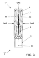
- Fig. 3 another embodiment is shown.
- the stopper 3 the holding element 5 and the protective element 7 is produced in one piece in the two-component injection molding process, wherein the stopper 3 and the holding member 5 of an identical elastic material and the protective element 7 formed of a harder material are.
- the gas supply takes place according to FIG. 3 via longitudinal gas supply slots 33, which extend between the protective element 7 and the stopper 3.
- the gas supply does not take place through longitudinal slots 33, but over in the upper region of the protective element 7 arranged transverse to the longitudinal axis openings 23 and additionally over transverse to the longitudinal axis 21 extending openings 31 in the protective element 7 in Height of the lower part of the needle 4.
- the protective element 7 may have outer-walled ribs, for example, parallel can be arranged to the longitudinal axis 21 of the protective element 7. Ribs improve the grip of the protective element 7.
Abstract
Description
Die Erfindung betrifft einen Nadelschutz für eine Glasspritze, der einen Verschlußstopfen, ein im wesentlichen die Form eines Hohlzylinders aufweisendes Halteelement mit einer Öffnung zum Aufnehmen eines Abschnitts eines Spritzenkörpers der Glasspritze und ein zugeordnetes, im wesentlichen die Form eines Hohlzylinders aufweisendes Schutzelement aufweist, wobei der Verschlußstopfen und das Halteelement aus einem elastischen Material und das Schutzelement aus einem härteren Material gebildet sind.The invention relates to a needle guard for a glass syringe, which comprises a stopper, a holding member substantially in the form of a hollow cylinder with an opening for receiving a portion of a syringe body of Glass syringe and an associated, substantially the shape of a hollow cylinder having protective element comprising, wherein the plug and the retaining element made of an elastic material and the protective element of a harder Material are formed.
Es ist bekannt, daß Glasspritzen mit Nadeln, die im allgemeinen mit dem Spritzenkörper beispielsweise durch Klebemittel dauerhaft verbunden sind, mit einem aufschiebbaren Nadelschutz aus elastischem Material, wie Gummi, verschlossen werden können. Dieser Nadelschutz umschließt die Nadel und kann problemlos abgezogen werden. Ein derartiger Nadelschutz wird unter anderem in US 3,865,236 beschrieben.It is known that glass syringes with needles, generally with the syringe body For example, are permanently connected by adhesive, with a slide-on Needle guard made of elastic material, such as rubber, to be closed can. This needle guard encloses the needle and can easily be removed become. Such a needle guard is described inter alia in US 3,865,236.
Probleme treten auf, wenn die Glasspritze unterschiedlichen Temperaturen oder Luftdrücken ausgesetzt wird. In der Regel werden Glasspritzen, nachdem sie mit einer Flüssigkeit, die beispielsweise pharmazeutische Wirkstoffe enthält, gefüllt und mit dem bekannten Nadelschutz verschlossen worden sind, sterilisiert.Problems occur when the glass syringe has different temperatures or Is exposed to atmospheric pressure. In general, glass syringes after being with a liquid containing, for example, pharmaceutical agents, filled and were sealed with the known needle guard, sterilized.
Dabei werden sie hohen Temperaturen, zum Beispiel 121°C oder 134°C und einem Vakuum ausgesetzt, so daß sich der elastische Nadelschutz aufbläht. Dies führt häufig zu einer Lockerung des Nadelschutzes und zu einem Abrutschen von der Glasspritze. So kommt es bei der Sterilisation oft zu einem Abspringen des Nadelschutzes von der Glasspritze (engl. pop-off effect). They are high temperatures, for example, 121 ° C or 134 ° C and a Vacuum exposed, so that the elastic needle protection inflates. This often leads to a loosening of the needle guard and slipping off the glass syringe. So it comes in the sterilization often to jump off the needle guard from the glass syringe (English pop-off effect).
Es ist die Aufgabe der vorliegenden Erfindung, einen Nadelschutz anzugeben, bei dem die oben beschriebene Lockerung verhindert und die Zuführung von sterilisierenden Gasen durch Permeation verbessert wird. Weiterhin soll ein Nadelschutz angegeben werden, bei dem eine nachträgliche Manipulation der Spritzenfüllung sofort erkennbar ist.It is the object of the present invention to provide a needle guard, in which prevents the loosening described above and the supply of sterilizing Gases is improved by permeation. Furthermore, a needle guard is specified in which a subsequent manipulation of the syringe filling immediately is recognizable.
Diese Aufgabe wird bei einem Nadelschutz der aufgezeigten Gattung dadurch gelöst, daß der Verschlußstopfen und das elastische Halteelement aus gasdurchlässigem Material gebildet sind, wobei das Gas zur Sterilisation bestimmt ist. In Ausgestaltung der Erfindung sind in dem Schutzelement in Höhe des Verschlußstopfens Öffnungen angeordnet, wobei der Verschlußstopfen vorteilhafterweise aus einem pharmazeutischen Gummi gebildet ist. Der pharmazeutische Gummi kann aus SBR oder NBR oder BIIR oder CIIR gebildet sein. Nach einem Merkmal der Erfindung sind in dem Schutzelement quer zur Längsachse verlaufende Durchbrüche in Höhe der oberen Begrenzung des Spritzenkörpers am Beginn des Spritzenkonus angeordnet.This object is achieved with a needle guard of the indicated type thereby that the closure plug and the elastic retaining element of gas permeable Material are formed, wherein the gas is intended for sterilization. In design of the invention are openings in the protective element in the amount of the stopper arranged, wherein the plug advantageously from a pharmaceutical Rubber is formed. The pharmaceutical gum may be SBR or NBR or BIIR or CIIR. According to a feature of the invention are in the Protective element extending transversely to the longitudinal axis breakthroughs in height of the upper Limitation of the syringe body arranged at the beginning of the syringe cone.
Bei einer Variante der Erfindung sind bei einteiliger Ausbildung des Verschlußstopfens, des Halteelements und des Schutzelements zwischen dem Schutzelement und dem Verschlußstopfen längsverlaufende Gaszuführungsschlitze angeordnet. Es besteht die Möglichkeit, unterhalb der Gaszuführungsschlitze das Halteelement durch das Schutzelement bis zur äußeren Begrenzung des Schutzelements zu führen, wodurch eine zusätzliche formschlüssige Verbindung hergestellt und ein Gasdurchgang ermöglicht wird. Das Halteelement kann außenwandige Stufen aufweisen. Vorteilhafterweise weist das Halteelement ein Rastelement auf, das mit einem Rastelement des Spritzenkörpers verrastbar ist, wobei das Rastelement des Halteelements durch eine nach innen weisende Ringwulst und das Rastelement des Spritzenkörpers durch eine ringförmige Nut gebildet ist. In a variant of the invention are in one-piece design of the stopper, the retaining element and the protective element between the protective element and arranged the closure plug longitudinal gas supply slots. It exists the possibility of below the gas supply slots through the holding element to guide the protective element to the outer boundary of the protective element, whereby made an additional positive connection and a gas passage is possible. The holding element may have outer-walled steps. advantageously, the retaining element has a latching element which is provided with a latching element the syringe body is latched, wherein the locking element of the holding element by an inwardly facing annular bead and the locking element of the syringe body by an annular groove is formed.
Zweckmäßige Ausgestaltungen der Erfindung sind in den übrigen Unteransprüchen aufgezeigt.Advantageous embodiments of the invention are in the remaining subclaims demonstrated.
Ausführungsbeispiele der Erfindung werden nachfolgend erläutert. Es zeigen:
- Fig. 1
- einen Vertikalschnitt durch einen Nadelschutz mit Verschlußstopfen, der auf eine Glasspritze aufgeschoben ist;
- Fig. 2
- einen Vertikalschnitt durch eine weitere Ausführungsform eines Nadelschutzes, der auf eine Glasspritze aufgeschoben ist;
- Fig. 3
- einen Vertikalschnitt durch eine weitere Ausführungsform eines Nadelschutzes, der auf eine Glasspritze aufgeschoben ist und
- Fig. 4
- einen Vertikalschnitt durch eine weitere Ausführungsform eines Nadelschutzes, der auf eine Glasspritze aufgeschoben ist.
- Fig. 1
- a vertical section through a needle guard with plug, which is pushed onto a glass syringe;
- Fig. 2
- a vertical section through another embodiment of a needle guard, which is pushed onto a glass syringe;
- Fig. 3
- a vertical section through another embodiment of a needle guard, which is pushed onto a glass syringe and
- Fig. 4
- a vertical section through another embodiment of a needle guard, which is pushed onto a glass syringe.
Nach Fig. 1 weist der Nadelschutz 1 ein Halteelement 5, ein Schutzelement 7 und
einen Verschlussstopfen 3 auf. Das Halteelement 5 besteht aus einem elastischen
Material, beispielsweise aus einem thermoplastischen, vulkanisierten Elastomer
(TPE-V). Es ist im wesentlichen in der Form eines Hohlzylinders ausgebildet, der an
seinen Außenwänden Stufen 25, 27, 29 aufweist. Im aufgeschobenen Zustand nimmt
das zylinderförmige Halteelement 5 einen Abschnitt 6 des Spritzenkörpers 8 der
Glasspritze 2 auf. Das Halteelement 5 weist unterschiedliche Außendurchmesser auf,
wobei der Außendurchmesser des der Glasspritze 2 zugewandten Endabschnitts am
größten und der Außendurchmesser des anderen gegenüberliegenden Endabschnittes
am kleinsten ist. Der Außendurchmesser des zuletzt genannten Endabschnittes des
Halteelementes 5 ist so gewählt, daß er von dem Schutzelement 7 aufgenommen
werden kann. According to Fig. 1, the
Im aufgeschobenen Zustand hält das Halteelement 5 aufgrund seiner Elastizität den
Nadelschutz 1 auf der Glasspritze 2 und dichtet den Innenraum des Nadelschutzes 1
ab.In the deferred state holds the
Das Schutzelement 7 besteht aus einem formstabilen Material, wie beispielsweise
Polypropylen, das im Vergleich zu dem Halteelement 5 und zu dem Verschlussstopfen
3 kaum elastisch ist. Das Schutzelement 7 ist im wesentlichen als Hohlzylinder
ausgebildet, der nach dem Aufsetzen des Nadelschutzes 1 auf die Glasspritze 2 die
Nadel 4 umschließt. Das zylinderförmige Schutzelement 7 kann entlang seiner
Längsachse 21 unterschiedliche Innendurchmesser aufweisen, wobei der Innendurchmesser
des dem Halteelement 5 zugewandten Endabschnittes so bemessen ist,
daß der entsprechende Endabschnitt des Halteelementes 5 aufgenommen werden
kann. Der andere Endabschnitt des Schutzelementes 7 weist einen solchen Innendurchmesser
auf, dass der Verschlussstopfen 3 aufnehmbar ist. Das Schutzelement 7
und das Halteelement 5 sind einteilig mittels Zwei-Komponenten-Spritzgießverfahren
hergestellt und dauerhaft miteinander verbunden, in dem das Schutzelement
7 aus PP und das Halteelement aus TPE-V gefertigt sind. Das Schutzelement 7
ist an seinem der Spritze abgewandten Ende offen, könnte aber auch geschlossen
sein. Es weist zwei Halterungen 9, 11 auf, die den Verschlussstopfen 3 an einer vorbestimmten
Position halten. Im Bereich des Verschlußstopfens 3 weist das Schutzelement
7 Öffnungen 23 auf, die in diesem Ausführungsbeispiel länglich ausgebildet
sind und quer zur Längsachse 21 des im wesentlichen zylinderförmigen Schutzelementes
7 verlaufen. Die Öffnungen 23 haben die Aufgabe, sterilisierende Gase durch
Permeation durch den Verschlußstopfen 3 eindringen zu lassen.The
Der Verschlußstopfen 3 besteht aus einem elastischen pharmazeutischen Gummi,
z. B. SBR (Styrol Butadien Rubber) oder NBR (Natural Butadien Rubber) oder BIIR
(Brom Isobutene Isoprene Rubber) oder CIIR (Chlor Isobutene Isoprene Rubber) und
ist gasdurchlässig. Der Verschlußstopfen 3 ist zylinderförmig ausgebildet und weist
einen Außendurchmesser auf, der im wesentlichen gleich dem Innendurchmesser des
dem Spritzenkörper 8 abgewandten Endabschnittes des Schutzelementes 7 ist. Im
aufgesetzten Zustand dringt die Nadel 4 der Glasspritze 2 in den Verschlußstopfen 3
ein, so daß die Nadel 4 verschlossen ist.The
Da der erfindungsgemäße Nadelschutz 1 zu einem großen Teil aus dem Schutzelement
7 besteht, das im Vergleich zu dem Halteelement 5 und dem Verschlußstopfen
3 kaum elastisch ist, tritt eine unerwünschte Lockerung des Nadelschutzes 1 aufgrund
von unterschiedlichen Temperaturen oder Luftdrücken kaum auf.Since the
Eine weitere Ausführungsform ist in Fig. 2 dargestellt. Auch hier besteht der erfindungsgemäße
Nadelschutz 1 aus einem Halteelement 5, einem Schutzelement 7 und
einem Verschlußstopfen 3. Während das Schutzelement 7 und der Verschlußstopfen
3 im Vergleich zur ersten Ausführungsform unverändert sind, weist das Halteelement
5 hier ein Rastelement 15 auf, das in dem in Fig. 2 gezeigten aufgesetzten Zustand
mit einem Rastelement 10 des Spritzenkörpers 8 unlösbar verrastet ist. Das Rastelement
15 des Halteelements 5 ist eine Ringwulst und das Rastelement 10 des Spritzenkörpers
8 eine ringförmige Erweiterung oder Vertiefung. Auf diese Art ist das
Halteelement 5 mit dem Spritzenkörper 8 dauerhaft verbunden. In anderen Ausführungsbeispielen
könnte das Halteelement 5 auch durch andere Verbindungsmittel,
zum Beispiel durch Klebemittel, unlösbar mit dem Spritzenkörper 8 verbunden sein.
Das Halteelement 5 weist angrenzend an die dem Spritzenkörper 8 abgewandte Seite
des Rastelements 15 eine Sollbruchstelle 12 auf, die als umlaufende Querschnittsschwächung
ausgebildet ist. Die Sollbruchstelle 12 kann auch auf eine andere Art
ausgebildet sein, beispielsweise durch Schlitze. Aufgabe der Sollbruchstelle ist die
unmittelbare Sichtbarmachung einer Manipulation an der Spritzenfüllung. Beim Abnehmen
des Nadelschutzes 1 gemäß dem in Fig. 2 gezeigten Ausführungsbeispiel
wird das Rastelement 15 an der Sollbruchstelle 12 vom dem Halteelement 5 abgetrennt
und verbleibt am Spritzenkörper 8. Wird der auf diese Weise beschädigte Nadelschutz
1 wieder auf die Glasspritze 2 aufgeschoben, so ist das vorherige Abnehmen
des Nadelschutzes 1 an dem an der Sollbruchstelle 12 durchbrochenen Halteelement
5 erkennbar.Another embodiment is shown in FIG. Again, the invention consists
Needle
In Fig. 3 ist eine weitere Ausführungsform dargestellt. Im Vergleich zu den Ausführungen
nach den Fig. 1 und 2 sind der Verschlußstopfen 3, das Halteelement 5 und
das Schutzelement 7 einteilig im Zwei-Komponenten-Spritzgießverfahren hergestellt,
wobei der Verschlußstopfen 3 und das Halteelement 5 aus einem identischen
elastischen Material und das Schutzelement 7 aus einem härteren Material gebildet
sind. Die Gaszuführung erfolgt nach Fig. 3 über längsverlaufende Gaszuführungsschlitze
33, die zwischen dem Schutzelement 7 und dem Verschlußstopfen 3 verlaufen.In Fig. 3, another embodiment is shown. Compared to the
Im Gegensatz zur Ausführung nach Fig. 3 erfolgt nach Fig. 4 die Gaszuführung nicht
durch längsverlaufende Schlitze 33, sondern über im oberen Bereich des Schutzelements
7 angeordnete quer zur Längsachse verlaufende Öffnungen 23 und zusätzlich
über quer zur Längsachse 21 verlaufende Durchbrüche 31 in dem Schutzelement 7 in
Höhe des unteren Bereichs der Nadel 4.In contrast to the embodiment according to FIG. 3, according to FIG. 4, the gas supply does not take place
through
Das Schutzelement 7 kann außenwandige Rippen aufweisen, die beispielsweise parallel
zur Längsachse 21 des Schutzelementes 7 angeordnet sein können. Die Rippen
verbessern die Griffigkeit des Schutzelements 7. The
- 11
- Nadelschutzneedle guard
- 22
- Glasspritzeglass syringe
- 33
- Verschlußstopfenplugs
- 44
- Nadelneedle
- 55
- Halteelementretaining element
- 66
- Abschnitt des SpritzenkörpersSection of the syringe body
- 77
- Schutzelementprotection element
- 88th
- Spritzenkörpersyringe body
- 99
- Halterungenbrackets
- 1010
- Rastelement von 8Locking element of 8
- 1111
- Halterungbracket
- 1212
- SollbruchstelleBreaking point
- 1515
- Rastelement von 5Locking element of 5
- 2121
- Längsachselongitudinal axis
- 2323
- Öffnungenopenings
- 2525
- außenwandige Stufen von 5outside walls of 5
- 2727
- außenwandige Stufen von 5outside walls of 5
- 2929
- außenwandige Stufen von 5outside walls of 5
- 3131
- quer zur Längsachse verlaufende DurchbrücheTransverse to the longitudinal axis extending openings
- 3333
- längsverlaufende Gaszuführungsschlitzelongitudinal gas supply slots
Claims (15)
Applications Claiming Priority (2)
| Application Number | Priority Date | Filing Date | Title |
|---|---|---|---|
| EP03017423A EP1502616A1 (en) | 2003-08-01 | 2003-08-01 | Needle protector for a glass syringe |
| EP03017423 | 2003-08-01 |
Publications (3)
| Publication Number | Publication Date |
|---|---|
| EP1502617A1 true EP1502617A1 (en) | 2005-02-02 |
| EP1502617B1 EP1502617B1 (en) | 2013-03-27 |
| EP1502617B2 EP1502617B2 (en) | 2022-04-27 |
Family
ID=33522329
Family Applications (2)
| Application Number | Title | Priority Date | Filing Date |
|---|---|---|---|
| EP03017423A Withdrawn EP1502616A1 (en) | 2003-08-01 | 2003-08-01 | Needle protector for a glass syringe |
| EP04018070.5A Active EP1502617B2 (en) | 2003-08-01 | 2004-07-30 | Needle protector for a glass syringe |
Family Applications Before (1)
| Application Number | Title | Priority Date | Filing Date |
|---|---|---|---|
| EP03017423A Withdrawn EP1502616A1 (en) | 2003-08-01 | 2003-08-01 | Needle protector for a glass syringe |
Country Status (2)
| Country | Link |
|---|---|
| US (1) | US7387617B2 (en) |
| EP (2) | EP1502616A1 (en) |
Cited By (1)
| Publication number | Priority date | Publication date | Assignee | Title |
|---|---|---|---|---|
| WO2011098831A1 (en) * | 2010-02-11 | 2011-08-18 | Barry Peter Liversidge | Medical needle cover arrangement |
Families Citing this family (47)
| Publication number | Priority date | Publication date | Assignee | Title |
|---|---|---|---|---|
| ATE347390T1 (en) * | 2003-02-11 | 2006-12-15 | Salvus Technology Ltd | SAFETY PIN |
| US8827961B2 (en) * | 2005-02-03 | 2014-09-09 | West Pharmaceutical Services, Inc. | Safety needle |
| US8235950B2 (en) * | 2005-02-03 | 2012-08-07 | Salvus Technology GmbH | Safety needle |
| US8597255B2 (en) * | 2005-02-03 | 2013-12-03 | Salvus Technology Limited | Safety needle |
| US9352079B2 (en) * | 2005-02-25 | 2016-05-31 | Salvus Technology Limited | Safety needle accessory |
| DE102005054075A1 (en) * | 2005-11-12 | 2007-05-16 | Vetter & Co Apotheker | Needle attachment for a syringe or carpule |
| DE102005058133A1 (en) | 2005-11-30 | 2007-05-31 | Schott Ag | Syringe, has sealing element and syringe body whereby annular, flexible deformable area can be pressed in sealing manner, by means of closing cap, on outer surface of cannula |
| WO2007124474A2 (en) * | 2006-04-21 | 2007-11-01 | West Pharmaceutical Services, Inc. | Needle shield |
| WO2008005441A2 (en) * | 2006-07-05 | 2008-01-10 | Jms Company, Ltd | Needle cover with site preparation tip |
| GB0615589D0 (en) * | 2006-08-04 | 2006-09-13 | Salvus Technology Ltd | Safety needle accessory |
| WO2008067467A2 (en) * | 2006-11-29 | 2008-06-05 | West Pharmaceutical Services, Inc. | Syringe cartridge system |
| WO2008077484A1 (en) * | 2006-12-21 | 2008-07-03 | Arzneimittel Gmbh Apotheker Vetter & Co. Ravensburg | Attachment for a syringe and/or cartridge and method for the production thereof |
| FR2913200B1 (en) * | 2007-03-02 | 2009-12-11 | Becton Dickinson France | NEEDLE PROTECTION DEVICE |
| FR2913201B1 (en) * | 2007-03-02 | 2009-11-20 | Becton Dickinson France | PROTECTION FOR COVERING THE END OF AN ADMINISTRATION DEVICE OR A SUBASSEMBLY, SUBASSEMBLY, AND ADMINISTRATION DEVICE |
| CN101868270B (en) * | 2007-09-25 | 2013-10-16 | 贝克顿迪金森法国公司 | Autoinjector with deshielder comprising tamper evidence means |
| US9656019B2 (en) | 2007-10-02 | 2017-05-23 | Medimop Medical Projects Ltd. | Apparatuses for securing components of a drug delivery system during transport and methods of using same |
| US10420880B2 (en) | 2007-10-02 | 2019-09-24 | West Pharma. Services IL, Ltd. | Key for securing components of a drug delivery system during assembly and/or transport and methods of using same |
| WO2009044401A2 (en) | 2007-10-02 | 2009-04-09 | Yossi Gross | External drug pump |
| GB0719876D0 (en) * | 2007-10-11 | 2007-11-21 | Weston Terence E | Safety needle |
| US9526846B2 (en) * | 2009-08-19 | 2016-12-27 | Safety Syringes, Inc. | Patient-contact activated needle stick safety device |
| EP2548597B1 (en) * | 2010-03-18 | 2016-08-10 | Daikyo Seiko, LTD. | Syringe needle cap |
| US8512295B2 (en) | 2010-08-19 | 2013-08-20 | West Pharmaceutical Services, Inc. | Rigid needle shield |
| EP2548596A1 (en) * | 2011-07-20 | 2013-01-23 | Sanofi-Aventis Deutschland GmbH | Needle shield assembly |
| FR2992222B1 (en) * | 2012-06-22 | 2015-06-19 | Aguettant Lab | PROTECTIVE DEVICE FOR EQUIPPING AN INJECTION DEVICE HAVING A CONNECTION TIP |
| JP2014090805A (en) * | 2012-11-01 | 2014-05-19 | Otsuka Techno Kk | Needle cover, needle assembly, and syringe with needle |
| DE102012022359A1 (en) | 2012-11-15 | 2014-05-15 | Vetter Pharma-Fertigung GmbH & Co. KG | Attachment for a syringe or carpule |
| FR3002739B1 (en) * | 2013-03-01 | 2016-01-08 | Transformation Des Elastomeres A Usages Medicaux Et Ind Soc D | NEEDLE PROTECTION DEVICE. |
| WO2014141471A1 (en) * | 2013-03-15 | 2014-09-18 | テルモ株式会社 | Syringe assembly, syringe assembly packaging, and pre-filled syringe |
| JP6104366B2 (en) * | 2013-03-26 | 2017-03-29 | テルモ株式会社 | Elastic cap and assembly for syringe having the same |
| JP1552665S (en) | 2014-05-08 | 2016-06-27 | ||
| JP1528650S (en) | 2014-06-20 | 2015-07-13 | ||
| US20170333641A1 (en) | 2014-10-30 | 2017-11-23 | Hoffmann-La Roche Inc. | Syringe and method of preparing syringe |
| EP3275485A4 (en) * | 2015-03-26 | 2018-06-27 | Terumo Kabushiki Kaisha | Syringe cap, syringe assembly, and prefilled syringe |
| US10149943B2 (en) | 2015-05-29 | 2018-12-11 | West Pharma. Services IL, Ltd. | Linear rotation stabilizer for a telescoping syringe stopper driverdriving assembly |
| US10576207B2 (en) | 2015-10-09 | 2020-03-03 | West Pharma. Services IL, Ltd. | Angled syringe patch injector |
| US9987432B2 (en) | 2015-09-22 | 2018-06-05 | West Pharma. Services IL, Ltd. | Rotation resistant friction adapter for plunger driver of drug delivery device |
| US10086145B2 (en) | 2015-09-22 | 2018-10-02 | West Pharma Services Il, Ltd. | Rotation resistant friction adapter for plunger driver of drug delivery device |
| CN113648488B (en) | 2015-10-09 | 2024-03-29 | 西医药服务以色列分公司 | Curved fluid path attachment to prefilled fluid reservoir |
| WO2017127215A1 (en) | 2016-01-21 | 2017-07-27 | Medimop Medical Projects Ltd. | Needle insertion and retraction mechanism |
| CN113041432B (en) | 2016-01-21 | 2023-04-07 | 西医药服务以色列有限公司 | Medicament delivery device comprising a visual indicator |
| EP3405227B1 (en) | 2016-01-21 | 2020-06-17 | West Pharma. Services Il, Ltd. | Force containment in an automatic injector |
| US11389597B2 (en) | 2016-03-16 | 2022-07-19 | West Pharma. Services IL, Ltd. | Staged telescopic screw assembly having different visual indicators |
| EP3431126A4 (en) * | 2016-03-17 | 2019-11-27 | Terumo Kabushiki Kaisha | Syringe assembly, syringe assembly packaging, and prefilled syringe |
| US10376647B2 (en) | 2016-03-18 | 2019-08-13 | West Pharma. Services IL, Ltd. | Anti-rotation mechanism for telescopic screw assembly |
| CN109562229B (en) | 2016-08-01 | 2021-07-13 | 西医药服务以色列有限公司 | Anti-rotation medicine barrel pin |
| EP3630226A1 (en) | 2017-05-30 | 2020-04-08 | West Pharma. Services Il, Ltd. | Modular drive train for wearable injector |
| CA3077844A1 (en) * | 2020-04-03 | 2021-10-03 | Duoject Medical Systems Inc. | Method of sanitizing a medical device |
Citations (4)
| Publication number | Priority date | Publication date | Assignee | Title |
|---|---|---|---|---|
| EP0876824A2 (en) * | 1997-05-09 | 1998-11-11 | Bünder Glas GmbH | Needle guard for glass syringes with bonded needles |
| FR2777787A1 (en) * | 1998-04-22 | 1999-10-29 | Stelmi Trading International | Syringe needle guard comprising rigid outer shell over-molded onto supple liner with axial cavity for needle holder |
| WO2002074367A2 (en) * | 2001-03-15 | 2002-09-26 | Becton Dickinson And Company | Syringe and needle sheidl assembly and method of sterilizing such assembly |
| US6551286B1 (en) * | 1999-11-11 | 2003-04-22 | Albert Louis Victor Jozef Claessens | Safety cap for a cannula |
Family Cites Families (13)
| Publication number | Priority date | Publication date | Assignee | Title |
|---|---|---|---|---|
| FR2118339A5 (en) * | 1970-12-15 | 1972-07-28 | Sedat | Syringe cap - comprising complementary rubber and plastic caps which also become the plunger |
| US3865236A (en) | 1973-03-16 | 1975-02-11 | Becton Dickinson Co | Needle shield |
| US4111326A (en) * | 1976-03-04 | 1978-09-05 | Becton, Dickinson And Company | Closure for air evacuated container |
| JPS5918427B2 (en) * | 1979-10-09 | 1984-04-27 | テルモ株式会社 | gasket for syringe |
| US4872552A (en) * | 1988-11-16 | 1989-10-10 | Mid-South Products Engineering, Inc. | Safety packaging for hypodermic syringes with needles and the like |
| US4964866A (en) † | 1989-11-22 | 1990-10-23 | Becton, Dickinson And Company | Needle sheath assembly |
| US4986818A (en) † | 1990-03-30 | 1991-01-22 | Becton, Dickinson And Company | Syringe assembly |
| DE4234319A1 (en) * | 1992-10-12 | 1994-04-14 | Wimmer Pharma Gummi Gmbh | Process for producing a needle protection cap and needle protection cap for attaching or sliding onto a syringe needle |
| US5344404A (en) * | 1993-08-13 | 1994-09-06 | Becton, Dickinson And Company | Syringe assembly having a non-resuable needle shield |
| FR2816848B1 (en) † | 2000-11-17 | 2003-06-20 | Rumpler Technologies | PROTECTION DEVICE FOR SYRINGE NEEDLE |
| DE10127779A1 (en) † | 2001-06-01 | 2002-12-12 | Vetter & Co Apotheker | Twist closure for primary packaging of pharmaceuticals, comprising channels between closure parts to allow flow of sterilizing vapor to closure contact surfaces |
| US6821267B2 (en) * | 2002-03-07 | 2004-11-23 | Baxter International | Luer tip cap having reduced removal force |
| DE10316127A1 (en) * | 2003-04-09 | 2004-11-04 | Arzneimittel Gmbh Apotheker Vetter & Co. Ravensburg | Pre-filled syringe or cartridge for medical purposes |
-
2003
- 2003-08-01 EP EP03017423A patent/EP1502616A1/en not_active Withdrawn
-
2004
- 2004-07-30 EP EP04018070.5A patent/EP1502617B2/en active Active
- 2004-08-02 US US10/912,706 patent/US7387617B2/en active Active
Patent Citations (4)
| Publication number | Priority date | Publication date | Assignee | Title |
|---|---|---|---|---|
| EP0876824A2 (en) * | 1997-05-09 | 1998-11-11 | Bünder Glas GmbH | Needle guard for glass syringes with bonded needles |
| FR2777787A1 (en) * | 1998-04-22 | 1999-10-29 | Stelmi Trading International | Syringe needle guard comprising rigid outer shell over-molded onto supple liner with axial cavity for needle holder |
| US6551286B1 (en) * | 1999-11-11 | 2003-04-22 | Albert Louis Victor Jozef Claessens | Safety cap for a cannula |
| WO2002074367A2 (en) * | 2001-03-15 | 2002-09-26 | Becton Dickinson And Company | Syringe and needle sheidl assembly and method of sterilizing such assembly |
Cited By (2)
| Publication number | Priority date | Publication date | Assignee | Title |
|---|---|---|---|---|
| WO2011098831A1 (en) * | 2010-02-11 | 2011-08-18 | Barry Peter Liversidge | Medical needle cover arrangement |
| US10213561B2 (en) | 2010-02-11 | 2019-02-26 | Tip-Top.Com Ltd | Medical needle cover arrangement |
Also Published As
| Publication number | Publication date |
|---|---|
| EP1502616A1 (en) | 2005-02-02 |
| US7387617B2 (en) | 2008-06-17 |
| US20050038391A1 (en) | 2005-02-17 |
| EP1502617B1 (en) | 2013-03-27 |
| EP1502617B2 (en) | 2022-04-27 |
Similar Documents
| Publication | Publication Date | Title |
|---|---|---|
| EP1502617B1 (en) | Needle protector for a glass syringe | |
| EP0397951B1 (en) | Syringe for medical purposes | |
| EP0917882B1 (en) | Syringe particularly a prefilled syringe or ampoule | |
| DE69725282T2 (en) | Sealing and protective arrangement for cannulas | |
| DE60113399T2 (en) | PRE-FILLED SYRINGE | |
| DE69925205T2 (en) | Needle guard for prefilled syringe | |
| DE1098167B (en) | Container with a hypodermic needle | |
| DE19638940C2 (en) | Prefilled syringe for medical purposes | |
| DE19956243A1 (en) | Tip cap unit for a syringe cylinder comprises inner and outer caps and a sleeve interacting in such a way that the inner cap can be removed only after the outer cap has been removed | |
| DE2647624A1 (en) | LOCK WITH HOLDER FOR A CONTAINER | |
| DE2930617A1 (en) | PROTECTIVE CAP FOR A SAMPLE NEEDLE | |
| DE3532560A1 (en) | LOCKING DEVICE FOR THE MOUTHPIECE OF AN ENDOSCOPE | |
| DE102007005407A1 (en) | Cap for a container for holding medical fluids and container for receiving medical fluids | |
| DE2419435A1 (en) | INJECTION SYRINGE | |
| DE112015006549T5 (en) | FILTER STRUCTURE FOR A SYRINGE AND A SINGLE CONTAINING SYRINGE | |
| DE3808688C2 (en) | ||
| DE19947998B4 (en) | Hypodermic syringe with needle guard | |
| EP2247274B1 (en) | Closure cap for containers | |
| EP0229204B1 (en) | Medical syringe | |
| DE102011111552A1 (en) | Syringe, has closure including safety cap and closure cap that tightly closes needle socket, where safety cap encompasses closure cap and is fastened to needle socket by retaining ring, and caps are formed in single-piece | |
| DE858299C (en) | Injection ampoule | |
| DE2503032C2 (en) | Injection syringe with a sealed needle cap | |
| DE102015107631A1 (en) | Syringe with closure | |
| DE102017005791A1 (en) | Transfer device for fluid transfer | |
| DE2149550A1 (en) | DEVICE FOR POURING LIQUIDS INTO BODY CELLS OR VESSELS, OR SUCTIONING LIQUIDS FROM SUCH |
Legal Events
| Date | Code | Title | Description |
|---|---|---|---|
| PUAI | Public reference made under article 153(3) epc to a published international application that has entered the european phase |
Free format text: ORIGINAL CODE: 0009012 |
|
| AK | Designated contracting states |
Kind code of ref document: A1 Designated state(s): AT BE BG CH CY CZ DE DK EE ES FI FR GB GR HU IE IT LI LU MC NL PL PT RO SE SI SK TR |
|
| AX | Request for extension of the european patent |
Extension state: AL HR LT LV MK |
|
| 17P | Request for examination filed |
Effective date: 20050419 |
|
| AKX | Designation fees paid |
Designated state(s): AT BE BG CH CY CZ DE DK EE ES FI FR GB GR HU IE IT LI LU MC NL PL PT RO SE SI SK TR |
|
| RAP1 | Party data changed (applicant data changed or rights of an application transferred) |
Owner name: GERRESHEIMER BUENDE GMBH |
|
| 17Q | First examination report despatched |
Effective date: 20100804 |
|
| GRAP | Despatch of communication of intention to grant a patent |
Free format text: ORIGINAL CODE: EPIDOSNIGR1 |
|
| GRAS | Grant fee paid |
Free format text: ORIGINAL CODE: EPIDOSNIGR3 |
|
| GRAA | (expected) grant |
Free format text: ORIGINAL CODE: 0009210 |
|
| STAA | Information on the status of an ep patent application or granted ep patent |
Free format text: STATUS: THE PATENT HAS BEEN GRANTED |
|
| AK | Designated contracting states |
Kind code of ref document: B1 Designated state(s): AT BE BG CH CY CZ DE DK EE ES FI FR GB GR HU IE IT LI LU MC NL PL PT RO SE SI SK TR |
|
| REG | Reference to a national code |
Ref country code: GB Ref legal event code: FG4D Free format text: NOT ENGLISH |
|
| REG | Reference to a national code |
Ref country code: CH Ref legal event code: EP |
|
| REG | Reference to a national code |
Ref country code: AT Ref legal event code: REF Ref document number: 602973 Country of ref document: AT Kind code of ref document: T Effective date: 20130415 |
|
| REG | Reference to a national code |
Ref country code: IE Ref legal event code: FG4D Free format text: LANGUAGE OF EP DOCUMENT: GERMAN |
|
| REG | Reference to a national code |
Ref country code: DE Ref legal event code: R096 Ref document number: 502004014081 Country of ref document: DE Effective date: 20130523 |
|
| PG25 | Lapsed in a contracting state [announced via postgrant information from national office to epo] |
Ref country code: SE Free format text: LAPSE BECAUSE OF FAILURE TO SUBMIT A TRANSLATION OF THE DESCRIPTION OR TO PAY THE FEE WITHIN THE PRESCRIBED TIME-LIMIT Effective date: 20130327 Ref country code: BG Free format text: LAPSE BECAUSE OF FAILURE TO SUBMIT A TRANSLATION OF THE DESCRIPTION OR TO PAY THE FEE WITHIN THE PRESCRIBED TIME-LIMIT Effective date: 20130627 |
|
| PG25 | Lapsed in a contracting state [announced via postgrant information from national office to epo] |
Ref country code: GR Free format text: LAPSE BECAUSE OF FAILURE TO SUBMIT A TRANSLATION OF THE DESCRIPTION OR TO PAY THE FEE WITHIN THE PRESCRIBED TIME-LIMIT Effective date: 20130628 Ref country code: FI Free format text: LAPSE BECAUSE OF FAILURE TO SUBMIT A TRANSLATION OF THE DESCRIPTION OR TO PAY THE FEE WITHIN THE PRESCRIBED TIME-LIMIT Effective date: 20130327 Ref country code: SI Free format text: LAPSE BECAUSE OF FAILURE TO SUBMIT A TRANSLATION OF THE DESCRIPTION OR TO PAY THE FEE WITHIN THE PRESCRIBED TIME-LIMIT Effective date: 20130327 |
|
| REG | Reference to a national code |
Ref country code: NL Ref legal event code: VDEP Effective date: 20130327 |
|
| PG25 | Lapsed in a contracting state [announced via postgrant information from national office to epo] |
Ref country code: CZ Free format text: LAPSE BECAUSE OF FAILURE TO SUBMIT A TRANSLATION OF THE DESCRIPTION OR TO PAY THE FEE WITHIN THE PRESCRIBED TIME-LIMIT Effective date: 20130327 Ref country code: RO Free format text: LAPSE BECAUSE OF FAILURE TO SUBMIT A TRANSLATION OF THE DESCRIPTION OR TO PAY THE FEE WITHIN THE PRESCRIBED TIME-LIMIT Effective date: 20130327 Ref country code: EE Free format text: LAPSE BECAUSE OF FAILURE TO SUBMIT A TRANSLATION OF THE DESCRIPTION OR TO PAY THE FEE WITHIN THE PRESCRIBED TIME-LIMIT Effective date: 20130327 Ref country code: ES Free format text: LAPSE BECAUSE OF FAILURE TO SUBMIT A TRANSLATION OF THE DESCRIPTION OR TO PAY THE FEE WITHIN THE PRESCRIBED TIME-LIMIT Effective date: 20130708 Ref country code: NL Free format text: LAPSE BECAUSE OF FAILURE TO SUBMIT A TRANSLATION OF THE DESCRIPTION OR TO PAY THE FEE WITHIN THE PRESCRIBED TIME-LIMIT Effective date: 20130327 Ref country code: SK Free format text: LAPSE BECAUSE OF FAILURE TO SUBMIT A TRANSLATION OF THE DESCRIPTION OR TO PAY THE FEE WITHIN THE PRESCRIBED TIME-LIMIT Effective date: 20130327 Ref country code: PT Free format text: LAPSE BECAUSE OF FAILURE TO SUBMIT A TRANSLATION OF THE DESCRIPTION OR TO PAY THE FEE WITHIN THE PRESCRIBED TIME-LIMIT Effective date: 20130729 |
|
| PG25 | Lapsed in a contracting state [announced via postgrant information from national office to epo] |
Ref country code: PL Free format text: LAPSE BECAUSE OF FAILURE TO SUBMIT A TRANSLATION OF THE DESCRIPTION OR TO PAY THE FEE WITHIN THE PRESCRIBED TIME-LIMIT Effective date: 20130327 Ref country code: CY Free format text: LAPSE BECAUSE OF FAILURE TO SUBMIT A TRANSLATION OF THE DESCRIPTION OR TO PAY THE FEE WITHIN THE PRESCRIBED TIME-LIMIT Effective date: 20130327 |
|
| PLBI | Opposition filed |
Free format text: ORIGINAL CODE: 0009260 |
|
| BERE | Be: lapsed |
Owner name: GERRESHEIMER BUNDE G.M.B.H. Effective date: 20130731 |
|
| PG25 | Lapsed in a contracting state [announced via postgrant information from national office to epo] |
Ref country code: DK Free format text: LAPSE BECAUSE OF FAILURE TO SUBMIT A TRANSLATION OF THE DESCRIPTION OR TO PAY THE FEE WITHIN THE PRESCRIBED TIME-LIMIT Effective date: 20130327 |
|
| PLAX | Notice of opposition and request to file observation + time limit sent |
Free format text: ORIGINAL CODE: EPIDOSNOBS2 |
|
| 26 | Opposition filed |
Opponent name: BECTON, DICKINSON AND COMPANY Effective date: 20131220 |
|
| PG25 | Lapsed in a contracting state [announced via postgrant information from national office to epo] |
Ref country code: MC Free format text: LAPSE BECAUSE OF FAILURE TO SUBMIT A TRANSLATION OF THE DESCRIPTION OR TO PAY THE FEE WITHIN THE PRESCRIBED TIME-LIMIT Effective date: 20130327 Ref country code: IT Free format text: LAPSE BECAUSE OF FAILURE TO SUBMIT A TRANSLATION OF THE DESCRIPTION OR TO PAY THE FEE WITHIN THE PRESCRIBED TIME-LIMIT Effective date: 20130327 |
|
| REG | Reference to a national code |
Ref country code: CH Ref legal event code: PL |
|
| GBPC | Gb: european patent ceased through non-payment of renewal fee |
Effective date: 20130730 |
|
| REG | Reference to a national code |
Ref country code: DE Ref legal event code: R026 Ref document number: 502004014081 Country of ref document: DE Effective date: 20131220 |
|
| REG | Reference to a national code |
Ref country code: IE Ref legal event code: MM4A |
|
| PG25 | Lapsed in a contracting state [announced via postgrant information from national office to epo] |
Ref country code: BE Free format text: LAPSE BECAUSE OF NON-PAYMENT OF DUE FEES Effective date: 20130731 Ref country code: LI Free format text: LAPSE BECAUSE OF NON-PAYMENT OF DUE FEES Effective date: 20130731 Ref country code: CH Free format text: LAPSE BECAUSE OF NON-PAYMENT OF DUE FEES Effective date: 20130731 Ref country code: GB Free format text: LAPSE BECAUSE OF NON-PAYMENT OF DUE FEES Effective date: 20130730 |
|
| PLBB | Reply of patent proprietor to notice(s) of opposition received |
Free format text: ORIGINAL CODE: EPIDOSNOBS3 |
|
| PG25 | Lapsed in a contracting state [announced via postgrant information from national office to epo] |
Ref country code: IE Free format text: LAPSE BECAUSE OF NON-PAYMENT OF DUE FEES Effective date: 20130730 |
|
| REG | Reference to a national code |
Ref country code: AT Ref legal event code: MM01 Ref document number: 602973 Country of ref document: AT Kind code of ref document: T Effective date: 20130730 |
|
| PG25 | Lapsed in a contracting state [announced via postgrant information from national office to epo] |
Ref country code: AT Free format text: LAPSE BECAUSE OF NON-PAYMENT OF DUE FEES Effective date: 20130730 |
|
| PLAB | Opposition data, opponent's data or that of the opponent's representative modified |
Free format text: ORIGINAL CODE: 0009299OPPO |
|
| R26 | Opposition filed (corrected) |
Opponent name: BECTON, DICKINSON AND COMPANY Effective date: 20131220 |
|
| PG25 | Lapsed in a contracting state [announced via postgrant information from national office to epo] |
Ref country code: TR Free format text: LAPSE BECAUSE OF FAILURE TO SUBMIT A TRANSLATION OF THE DESCRIPTION OR TO PAY THE FEE WITHIN THE PRESCRIBED TIME-LIMIT Effective date: 20130327 |
|
| PG25 | Lapsed in a contracting state [announced via postgrant information from national office to epo] |
Ref country code: LU Free format text: LAPSE BECAUSE OF NON-PAYMENT OF DUE FEES Effective date: 20130730 Ref country code: HU Free format text: LAPSE BECAUSE OF FAILURE TO SUBMIT A TRANSLATION OF THE DESCRIPTION OR TO PAY THE FEE WITHIN THE PRESCRIBED TIME-LIMIT; INVALID AB INITIO Effective date: 20040730 |
|
| REG | Reference to a national code |
Ref country code: FR Ref legal event code: PLFP Year of fee payment: 13 |
|
| PLCK | Communication despatched that opposition was rejected |
Free format text: ORIGINAL CODE: EPIDOSNREJ1 |
|
| STAA | Information on the status of an ep patent application or granted ep patent |
Free format text: STATUS: THE PATENT HAS BEEN GRANTED |
|
| APAH | Appeal reference modified |
Free format text: ORIGINAL CODE: EPIDOSCREFNO |
|
| APBM | Appeal reference recorded |
Free format text: ORIGINAL CODE: EPIDOSNREFNO |
|
| APBP | Date of receipt of notice of appeal recorded |
Free format text: ORIGINAL CODE: EPIDOSNNOA2O |
|
| APBQ | Date of receipt of statement of grounds of appeal recorded |
Free format text: ORIGINAL CODE: EPIDOSNNOA3O |
|
| REG | Reference to a national code |
Ref country code: FR Ref legal event code: PLFP Year of fee payment: 14 |
|
| REG | Reference to a national code |
Ref country code: FR Ref legal event code: PLFP Year of fee payment: 15 |
|
| APBU | Appeal procedure closed |
Free format text: ORIGINAL CODE: EPIDOSNNOA9O |
|
| PUAH | Patent maintained in amended form |
Free format text: ORIGINAL CODE: 0009272 |
|
| STAA | Information on the status of an ep patent application or granted ep patent |
Free format text: STATUS: PATENT MAINTAINED AS AMENDED |
|
| 27A | Patent maintained in amended form |
Effective date: 20220427 |
|
| AK | Designated contracting states |
Kind code of ref document: B2 Designated state(s): AT BE BG CH CY CZ DE DK EE ES FI FR GB GR HU IE IT LI LU MC NL PL PT RO SE SI SK TR |
|
| REG | Reference to a national code |
Ref country code: DE Ref legal event code: R102 Ref document number: 502004014081 Country of ref document: DE |
|
| P01 | Opt-out of the competence of the unified patent court (upc) registered |
Effective date: 20230403 |
|
| PGFP | Annual fee paid to national office [announced via postgrant information from national office to epo] |
Ref country code: FR Payment date: 20230724 Year of fee payment: 20 Ref country code: DE Payment date: 20230720 Year of fee payment: 20 |