EP1510650B1 - Downhole surge pressure reduction and filtering apparatus - Google Patents
Downhole surge pressure reduction and filtering apparatus Download PDFInfo
- Publication number
- EP1510650B1 EP1510650B1 EP04105609A EP04105609A EP1510650B1 EP 1510650 B1 EP1510650 B1 EP 1510650B1 EP 04105609 A EP04105609 A EP 04105609A EP 04105609 A EP04105609 A EP 04105609A EP 1510650 B1 EP1510650 B1 EP 1510650B1
- Authority
- EP
- European Patent Office
- Prior art keywords
- tool
- fluid
- borehole
- pipe
- well
- Prior art date
- Legal status (The legal status is an assumption and is not a legal conclusion. Google has not performed a legal analysis and makes no representation as to the accuracy of the status listed.)
- Expired - Lifetime
Links
- 238000001914 filtration Methods 0.000 title claims description 9
- 230000009467 reduction Effects 0.000 title description 6
- 239000012530 fluid Substances 0.000 claims description 102
- 239000004568 cement Substances 0.000 claims description 41
- 239000002245 particle Substances 0.000 claims description 8
- 230000014759 maintenance of location Effects 0.000 claims description 6
- 238000000034 method Methods 0.000 claims description 3
- 239000013049 sediment Substances 0.000 description 35
- 239000000463 material Substances 0.000 description 12
- 238000005553 drilling Methods 0.000 description 10
- 230000015572 biosynthetic process Effects 0.000 description 9
- 238000005755 formation reaction Methods 0.000 description 9
- 238000004891 communication Methods 0.000 description 3
- 230000001627 detrimental effect Effects 0.000 description 3
- 239000000835 fiber Substances 0.000 description 3
- 238000003780 insertion Methods 0.000 description 3
- 230000037431 insertion Effects 0.000 description 3
- 239000002184 metal Substances 0.000 description 3
- 230000002706 hydrostatic effect Effects 0.000 description 2
- 230000013011 mating Effects 0.000 description 2
- 230000007246 mechanism Effects 0.000 description 2
- 239000012528 membrane Substances 0.000 description 2
- 239000011148 porous material Substances 0.000 description 2
- 239000004576 sand Substances 0.000 description 2
- 230000032258 transport Effects 0.000 description 2
- 239000004215 Carbon black (E152) Substances 0.000 description 1
- 238000009825 accumulation Methods 0.000 description 1
- 230000009286 beneficial effect Effects 0.000 description 1
- 230000000903 blocking effect Effects 0.000 description 1
- 238000010276 construction Methods 0.000 description 1
- 239000000356 contaminant Substances 0.000 description 1
- 238000011109 contamination Methods 0.000 description 1
- 238000005520 cutting process Methods 0.000 description 1
- 239000011152 fibreglass Substances 0.000 description 1
- 229930195733 hydrocarbon Natural products 0.000 description 1
- 150000002430 hydrocarbons Chemical class 0.000 description 1
- 238000002955 isolation Methods 0.000 description 1
- 238000004519 manufacturing process Methods 0.000 description 1
- 239000003129 oil well Substances 0.000 description 1
- 239000004033 plastic Substances 0.000 description 1
- 239000002861 polymer material Substances 0.000 description 1
- 238000005086 pumping Methods 0.000 description 1
- 230000004044 response Effects 0.000 description 1
- 230000000717 retained effect Effects 0.000 description 1
- 238000007789 sealing Methods 0.000 description 1
- 238000000926 separation method Methods 0.000 description 1
Images


Classifications
-
- E—FIXED CONSTRUCTIONS
- E21—EARTH DRILLING; MINING
- E21B—EARTH DRILLING, e.g. DEEP DRILLING; OBTAINING OIL, GAS, WATER, SOLUBLE OR MELTABLE MATERIALS OR A SLURRY OF MINERALS FROM WELLS
- E21B43/00—Methods or apparatus for obtaining oil, gas, water, soluble or meltable materials or a slurry of minerals from wells
- E21B43/02—Subsoil filtering
- E21B43/08—Screens or liners
-
- E—FIXED CONSTRUCTIONS
- E21—EARTH DRILLING; MINING
- E21B—EARTH DRILLING, e.g. DEEP DRILLING; OBTAINING OIL, GAS, WATER, SOLUBLE OR MELTABLE MATERIALS OR A SLURRY OF MINERALS FROM WELLS
- E21B21/00—Methods or apparatus for flushing boreholes, e.g. by use of exhaust air from motor
- E21B21/10—Valve arrangements in drilling-fluid circulation systems
- E21B21/103—Down-hole by-pass valve arrangements, i.e. between the inside of the drill string and the annulus
-
- E—FIXED CONSTRUCTIONS
- E21—EARTH DRILLING; MINING
- E21B—EARTH DRILLING, e.g. DEEP DRILLING; OBTAINING OIL, GAS, WATER, SOLUBLE OR MELTABLE MATERIALS OR A SLURRY OF MINERALS FROM WELLS
- E21B27/00—Containers for collecting or depositing substances in boreholes or wells, e.g. bailers, baskets or buckets for collecting mud or sand; Drill bits with means for collecting substances, e.g. valve drill bits
- E21B27/005—Collecting means with a strainer
-
- E—FIXED CONSTRUCTIONS
- E21—EARTH DRILLING; MINING
- E21B—EARTH DRILLING, e.g. DEEP DRILLING; OBTAINING OIL, GAS, WATER, SOLUBLE OR MELTABLE MATERIALS OR A SLURRY OF MINERALS FROM WELLS
- E21B33/00—Sealing or packing boreholes or wells
- E21B33/10—Sealing or packing boreholes or wells in the borehole
- E21B33/13—Methods or devices for cementing, for plugging holes, crevices, or the like
- E21B33/14—Methods or devices for cementing, for plugging holes, crevices, or the like for cementing casings into boreholes
-
- E—FIXED CONSTRUCTIONS
- E21—EARTH DRILLING; MINING
- E21B—EARTH DRILLING, e.g. DEEP DRILLING; OBTAINING OIL, GAS, WATER, SOLUBLE OR MELTABLE MATERIALS OR A SLURRY OF MINERALS FROM WELLS
- E21B37/00—Methods or apparatus for cleaning boreholes or wells
-
- E—FIXED CONSTRUCTIONS
- E21—EARTH DRILLING; MINING
- E21B—EARTH DRILLING, e.g. DEEP DRILLING; OBTAINING OIL, GAS, WATER, SOLUBLE OR MELTABLE MATERIALS OR A SLURRY OF MINERALS FROM WELLS
- E21B37/00—Methods or apparatus for cleaning boreholes or wells
- E21B37/10—Well swabs
-
- E—FIXED CONSTRUCTIONS
- E21—EARTH DRILLING; MINING
- E21B—EARTH DRILLING, e.g. DEEP DRILLING; OBTAINING OIL, GAS, WATER, SOLUBLE OR MELTABLE MATERIALS OR A SLURRY OF MINERALS FROM WELLS
- E21B43/00—Methods or apparatus for obtaining oil, gas, water, soluble or meltable materials or a slurry of minerals from wells
- E21B43/02—Subsoil filtering
- E21B43/10—Setting of casings, screens, liners or the like in wells
-
- E—FIXED CONSTRUCTIONS
- E21—EARTH DRILLING; MINING
- E21B—EARTH DRILLING, e.g. DEEP DRILLING; OBTAINING OIL, GAS, WATER, SOLUBLE OR MELTABLE MATERIALS OR A SLURRY OF MINERALS FROM WELLS
- E21B2200/00—Special features related to earth drilling for obtaining oil, gas or water
- E21B2200/05—Flapper valves
-
- E—FIXED CONSTRUCTIONS
- E21—EARTH DRILLING; MINING
- E21B—EARTH DRILLING, e.g. DEEP DRILLING; OBTAINING OIL, GAS, WATER, SOLUBLE OR MELTABLE MATERIALS OR A SLURRY OF MINERALS FROM WELLS
- E21B33/00—Sealing or packing boreholes or wells
- E21B33/10—Sealing or packing boreholes or wells in the borehole
- E21B33/13—Methods or devices for cementing, for plugging holes, crevices, or the like
- E21B33/14—Methods or devices for cementing, for plugging holes, crevices, or the like for cementing casings into boreholes
- E21B33/16—Methods or devices for cementing, for plugging holes, crevices, or the like for cementing casings into boreholes using plugs for isolating cement charge; Plugs therefor
- E21B33/165—Cementing plugs specially adapted for being released down-hole
Definitions
- the present invention provides a downhole surge pressure reduction apparatus for use in the oil well industry. More particularly, the invention provides a surge pressure reduction apparatus that is run into a well with a pipe string or other tubular to be cemented and facilitates the cementing by reducing surge pressure and inner well sediments during run-in.
- the borehole is typically lined with strings of pipe or tubulars (pipe or casing) to prevent the walls of the borehole from collapsing and to provide a reliable path for well production fluid, drilling mud and other fluids that are naturally present or that may be introduced into the well.
- the drill bit and drill string are removed and a string of pipe is lowered into the well to a predetermined position whereby the top of the pipe is at about the same height as the bottom of the existing string of pipe (liner).
- the new pipe string extends back to the surface of the well casing.
- the top of the pipe is fixed with a device such as a mechanical hanger.
- a column of cement is then pumped into the pipe or a smaller diameter run-in string and forced to the bottom of the borehole where it flows out of the pipe and flows upwards into an annulus defined by the borehole and pipe.
- the two principal functions of the cement between the pipe and the borehole are to restrict fluid movement between formations and to support the pipe.
- Cementing apparatus typically includes a number of different components made up at the surface prior to run-in. These include a tapered nose portion located at the downhole end of the pipe to facilitate insertion thereof into the borehole.
- a check valve at least partially seals the end of the tubular and prevents entry of well fluid during run-in while permitting cement to subsequently flow outwards.
- Another valve or plug typically located in a baffle collar above the cementing tool prevents the cement in the annulus from back flowing into the pipe.
- Components of the cementing apparatus are made of plastic, fibreglass or other disposable material that, like cement remaining in the pipe, can be drilled when the cementing is completed and the borehole is drilled to a new depth.
- surge pressure created as the pipe and cementing apparatus are lowered into the borehole filled with drilling mud or other well fluid. Because the end of the pipe is at least partially flow restricted, same of the well fluid is necessarily directed into the annular area between the borehole and the pipe. Rapid lowering of the pipe results in a corresponding increase or surge in pressure, at or below the pipe, generated by restricted fluid flow in the annulus.
- Surge pressure has many detrimental effects. For example, it can cause drilling fluid to be lost into the earth formation and it can weaken the exposed formation when the surge pressure in the borehole exceeds the formation pore pressure of the well. Additionally, surge pressure can cause a loss of cement to the formation during the cementing of the pipe due to formations that have become fractured by the surge pressure.
- An acceptable level would be a level at least where the drilling fluid pressure, including the surge pressure is less than the formation pore pressure to minimise the above detrimental effects.
- any reduction of surge pressure is beneficial because the more surge pressure is reduced, the faster the pipe can be run into the borehole and the more profitable a drilling operation becomes.
- baffle collars used at the top of cementing tools have been designed to permit the through flow of fluid during run-in by utilising valves that are held in a partially open position during run-in and then remotely closed later to prevent back flow of cement. While these designs have been somewhat successful, the flow of well fluid is still impeded by restricted passages. Subsequent closing of the valves in the cementing tool and the baffle collar is also problematic because of mechanical failures and contamination.
- Another problem encountered by prior art cementing apparatus relates to sediment, sand, drill cuttings and other particulates collected at the bottom of a newly drilled borehole and suspended within the drilling mud that fills the borehole prior to running-in a new pipe. Sediment at the borehole bottom becomes packed and prevents the pipe and cementing apparatus from being seated at the very bottom of the borehole after run-in. This misplacement of the cementing apparatus results in difficulties having the pipe in the well or at the wellhead. Also, the sediment below the cementing apparatus tends to be transported into the annulus with the cement where it has a detrimental effect on the quality of the cementing job. In those prior art designs that allow the drilling fluid to enter the pipe to reduce surge pressure, the fluid borne sediment can foul mechanical parts in the borehole and can subsequently contaminate the cement.
- the present invention provides a cementing apparatus for cementing in a borehole comprising:
- FIGS 1A and B are section views showing the surge reduction and cementing tool 100 of the present invention.
- Figures 9A , B are enlarged views of the lower portion of the tool.
- the tool 100 generally includes an outer body 110, a inner member 135 disposed within the outer body 110, a nose portion 120 and a baffle collar 125.
- Outer body 110 is preferably formed by the lower end of the pipe to be cemented in the borehole and the cementing tool 100 will typically be constructed and housed within the end of the pipe prior to being run-into the well.
- tubing tubular
- casing tubular
- string all relate to pipe used in a well or an operation within a well and are all used interchangeably herein.
- pipe assembly refers to a string of pipe, a hanger and a cementing tool all of which are run-into a borehole together on a run-in string of pipe. While the tool is shown in the Figures at the end of a tubular string, it will be understood that the tool described and claimed herein could also be inserted at any point in a string of tubulars.
- Nose portion 120 is installed at the lower end of outer body 110 as depicted in Figure 1B to facilitate insertion of the tool 100 into the borehole 115 and to add strength and support to the lower end of the apparatus 100.
- Figure 8 is an end view of the downhole end of the tool 100 showing the nose portion 120 with a plurality of radially spaced apertures 122 formed therearound and a centre aperture 124 formed therein. Apertures 122 allow the inflow of fluid into the tool 100 during run-in and centre aperture 124 allows cement to flow out into the borehole.
- inner member 135 Centrally disposed within the outer body 110 is inner member 135 providing a filtered path for well fluid during run-in and a path for cement into the borehole during the subsequent cementing job.
- inner member 135 is supported by nose portion 120.
- support structure 121 formed within nose portion 120 surrounds and supports the lower end of inner member 135.
- check valve 140 Disposed between the lower end of inner member 135 and nose portion 120 is check valve 140. The purpose of valve 140 is to restrict the flow of well fluid into the lower end of inner member 135 while allowing the outward flow of cement from the end of inner member as will be decried herein.
- check valve 140 is preferably a spring-loaded type valve having a ball to effectively seal the end of a tubular and withstand pressure generated during run-in.
- any device capable of restricting fluid flow in a single direction can be utilized and all are within the scope of the invention as claimed.
- FIG. 4 is an end view of a centralizer 145 depicting its design and showing specifically its construction of radial spokes 146 extending from the inner member 135 to the inside wall of outer body 110, whereby fluid can freely pass though the annular area 155 formed between inner member 135 and outer body 110. Also visible in Figures 1A, 1B and 4 are funnel-shaped traps 147 designed to catch and retain sediment and particles that flow into the annular area 155, preventing them from falling back towards the bottom of the well. In the preferred embodiment, the sediment traps are nested at an upper end of each centralizer 145. Depending upon the length of the inner member 135, any number of centralizers 145 and sediment traps can be utilized in a tool 100.
- Inner member 135 includes a inner portion formed therealong consisting of, in the preferred embodiment, perforations 160 extending therethrough to create a fluid path to the interior of the inner member 135.
- the perforations while allowing the passage of fluid to reduce pressure surge, are also designed to prevent the passage of sediment or particles, thereby ensuring that the fluid traveling up the tool and into the pipe string above will be free of contaminants.
- the terms "filtering” and “separating” will be used interchangeably herein and both related to the removal, separation or isolation of any type of particle or other contaminate from the fluid passing through the tool.
- the size, shape and number of the perforations 160 are variable depending upon run-in speed and pressure surge generated during lowering of the pipe.
- Various material can be used to increase or define the inner properties of the inner member.
- the inner member can be wrapped in or have installed in a membrane material made of corrosive resistant, polymer material and strengthened with a layer of braided metal wrapped therearound. Additionally, membrane material can be used to line the inside of the
- inner member 135 is secured within outer body 110 by a drillable cement ring 165 formed therearound.
- Inner member 135 terminates in a perforated cap 168 which can provide additional inner of fluids and, in an alternative embodiment, can also serve to catch a ball or other projectile used to actuate some device higher in the borehole.
- a space 180 that provides an accumulation point for cement being pumped into the tool 100.
- baffle collar 125 At the upper end of tool 100 is a funnel-shaped baffle collar 125.
- the baffle collar provides a seat for a plug or other device which travels down the pipe behind a column of cement that is urged out the bottom of tool 100 and into the annulus 130 formed therearound.
- the baffle collar is held within outer body 110 by cement or other drillable material.
- a mid-portion of baffle collar 125 includes by-pass holes 174 and by-pass channels 175 extending therefrom to provide fluid communication between the baffle collar 125 and space 180 therebelow.
- FIG. 1 is an enlarged section view showing the various components of the baffle collar.
- Figure 2A is a section view showing the by-pass channels 175 and the placement of the check valve 178.
- Figure 7 illustrates a plug and dart assembly 190, having landed in baffle collar 125 and sealed the fluid path of well fluid into the baffle collar through by-pass holes 174 and by-pass channels 175.
- the plug and dart assembly 190 are launched from the running string and urged downward in the pipe behind the column of cement that will be used to cement the pipe in the borehole 115.
- the plug and dart assembly 190 are designed to seat in the baffle collar 125 where they also function to prevent subsequent back flow of cement into the baffle collar 125 and the pipe (not shown) thereabove.
- FIG 3 is a section view showing an alternative embodiment of a baffle collar 300.
- the upper portion of the baffle collar 300 forms a male portion 301 with apertures 302 in fluid communication with by-pass channels 303.
- Male portion 301 is received by a plug and dart having a mating female portion formed therein.
- the apertures 302 in the male portion of the baffle collar are covered and sealed by the female portion of the plug and dart assembly (not shown).
- FIG. 5 illustrates a third embodiment of a baffle collar 400 for use in the tool of the present invention.
- a flapper valve 405 is propped open during run-in to allow well fluid to pass through the baffle collar 400 to relieve surge pressure.
- the flapper valve 405 is remotely closed by dropping a ball 410 into a seat 415 which allows the spring-loaded flapper valve 405 to close.
- the baffle collar 400 is sealed to the upper flow of fluid while the flapper valve 405 can be freely opened to allow the downward flow of cement.
- the plug and dart assembly (not shown) includes wavy formations which mate with the wavy 420 formations formed in the baffle collar 400.
- baffle collar 400 is particularly useful with a remotely locatable portable atmospheric chamber described hereafter and illustrated in Figures 13A-C .
- Figures 6A-C illustrate a plug 194 and dart 200 at the end of a run-in string 185.
- the run-in string transports the pipe into the borehole, provides a fluid path from the well surface and extends at least some distance into the pipe to be cemented.
- the run-in string provides a flow path therethrough for well fluid during run-in and for cement as it passes from the well surface to the cementing tool at the end of the pipe.
- An intermediate member 192 disposed within the plug 194 and having a centre aperture 197 therethrough, provides a seal for the nose of dart 200 ( Figure 6C ) that lands in the plug 194 and seals the flow path therethrough.
- FIG. 6B is a section view of the nose portion 190 of the plug 194 clearly showing the centre aperture 197 and by-pass apertures 193 of intermediate member 192.
- the by-pass apertures 193 are elliptical in shape.
- Figure 6C is a section view showing the plug 194 with dart 200 seated therein. Centre aperture 197 of the intermediate member 192 is sealed by the dart nose 198 and the by-pass apertures 193 are sealed by dart fin 201 once the intermediate member 192 is urged downward in interior of the plug 194 by the dart 200.
- Figures 6D-F illustrate an alternative embodiment in which the by-pass apertures 220 of an intermediate member 222 are sealed when the intermediate member 222 is urged downward in the interior of the plug 225 by the dart 200, thereby creating a metal to metal seal between the plug surface 227 and outer diameter portion 226 of intermediate member 222.
- the tool of the present invention is used in the same manner as those of the prior art.
- the drill string and bit are removed from the well leaving the borehole at least partially filled with drilling fluid.
- pipe is lowered into the borehole having the cementing tool of the present invention at a downhole end and a run-in tool at an upper end.
- the entire assembly is run into the well at the end of a run-in string, a string of tubulars typically having a smaller diameter than the pipe and capable of providing an upward flow path for well fluid during run-in and a downward flow path for cement during the cementing operation.
- the assembly minimises surge by passing well fluid through the radially spaced apertures 122 of nose portion and into the outer body 110 where it is filtered as it passes into the inner member 135. While some of the fluid will travel up the annulus 130 formed between the outer body 110 and the borehole 115, the tool 100 is designed to permit a greater volume of fluid to enter the interior of the tubular being run into the well. Arrows 182 in Figure 1B illustrate the path of fluid as it travels between outer body 110 and inner member 135. As the run-in operation continues and the pipe continues downwards in the borehole, the fluid level rises within inner member 135 reaching and filling space 180 between the upper end of the inner member 135 and the baffle collar 125.
- the fluid enters the baffle collar 125 through by-pass channels 175 and by-pass holes 174. Thereafter, the fluid can continue towards the surface of the well using the interior of the pipe and/or the inside diameter of the run-in string as a flow path.
- the pipe With the nose portion 120 of the tool at the bottom of the well and the upper end located either at the surface well head or near the end of the previously cemented pipe, the pipe may be hung in place, either at the well head or near the bottom of the preceding string through the remote actuation of a hanger, usually using a slip and cone mechanism to wedge the pipe in place. Cementing of the pipe in the borehole can then be accomplished by known methods, concluding with the seating of a plug assembly on or in a baffle collar.
- Figures 10A-C illustrate an alternative embodiment of the tool 500 wherein the perforations formed in an inner member 535 may be opened or closed depending upon well conditions or goals of the operator.
- an inner sleeve 501 is located within the inner member 535.
- the inner sleeve 501 has perforations 502 formed therein and can be manipulated to cause alignment or misalignment with the mating perforations 503 in the inner member 535.
- Figure 10A illustrates the inner member 535 having an inner sleeve 501 which has been manipulated to block the perforations 503 of the inner member 535.
- FIG. 10A the perforations of the inner member and the inner sleeve 502, 503 visible in Figure 10A at point “A” are misaligned, vertically blocking the flow of fluid therethrough.
- Figure 10B at point “B” illustrates the perforations 502, 503 vertically aligned whereby fluid can flow therethrough.
- the relationship between the inner sleeve 501 and inner member 135 is more closely illustrated in Figure 10C , showing the perforations 502, 503 of the inner sleeve 501 and inner member 535 aligned.
- Manipulation of the inner sleeve 501 within the inner member 535 to align or misalign perforations 502, 503 can be performed any number of ways. For example, a ball or other projectile can be dropped into the tool 100 moving the inner sleeve 501 to cause its perforations 503 to align or misalign with the perforations 502 in inner member 535. Alternatively, the manipulation can be performed with wireline. While the inner sleeve can be moved vertically in the embodiment depicted, it will be understood that the perforations 502, 503 could be aligned or misaligned through rotational as well as axial movement. For example, remote rotation of the sleeve could be performed with a projectile and a cam mechanism to impart rotational movement.
- the perforations 502, 503 would be opened during run-in to allow increased surge reduction and inner of well fluid as described herein. Once the tool has been run into the well, the perforations 502, 503 could be remotely misaligned or closed, thereby causing the cement to exit the tool directly through the centre aperture 124 in the nose portion 120 of the tool, rather than through the perforations and into the annulus 130 between the inner member 135 and the outer body 110.
- FIGs 11A and B show an alternative embodiment of a cementing tool 550 including a sediment trap 555 formed between an inner member 560 and an outer body 110.
- the sediment trap 555 is a cone-shaped structure having a tapered lower end extending from an upper end of nose portion 120 and continuing upwards and outwards in a conical shape towards outer body 110.
- An annular area 565 is thereby formed between the outer wall of sediment trap 555 and the inside wall of outer body 110 for the flow of well fluid during run-in.
- the direction of flow is illustrated by arrows 570 in Figure 11B .
- Figures 12A and B show an alternative embodiment of a tool 600, including an apparatus for displacing and removing sediment from the bottom of the borehole, thereby allowing the tool 600 to be more accurately placed at the bottom of the borehole prior to cementing.
- a tool 600 depicted in Figures 12A and B an annular area between the inner member 610 and outer body 110 is separated into an upper chamber 605 and a lower chamber 615 by a donut-shaped member 620.
- the upper chamber 605 because it is isolated from well fluid and sealed at the well surface, forms an atmospheric chamber as the tool 600 is run into the borehole.
- Donut-shaped member 620 is axially movable within outer body 110 but is fixed in place by a frangible member 625, the body of which is mounted in the interior of inner member 610. Pins 621 between the frangible member 625 and the donut-shaped member 620 hold the donut-shaped member in place.
- a ball or other projectile (not shown) is released from above the tool 600.
- the frangible member is fractured and the donut-shaped member 620 is released.
- the pressure differential between the upper 605 and lower 615 chambers of the tool causes the donut-shaped member 620 to move axially towards the well surface. This movement of the donut-shaped member 620 creates a suction in the lower chamber 615 of the tool which causes loose sediment (not shown) to be drawn into the lower chamber 615. In this manner, sediment is displaced from the borehole and the tool can be more accurately placed prior to a cementing job.
- FIGs 13A and B illustrate yet another embodiment of the tool 650, wherein a remotely locatable, atmospheric chamber 655 is placed in the interior of inner member 660.
- the annular area between inner member 660 and outer body 110 is divided into an upper 665 and lower 670 chambers with a donut-shaped member 675 dividing the two chambers. That portion of the inner member 680 extending through upper chamber 665 is not perforated but includes only a plurality of ports therearound.
- pressure in the upper and lower chambers remain equalized during run-in of the tool into the borehole.
- Atmospheric chamber 655 is contained within a tool 677.
- atmospheric chamber tool 677 is lowered into the borehole by any known method including a separate running string or wireline.
- the atmospheric chamber tool 677 lands on a shoulder 682 formed in the interior of the inner member 680 at which point apertures 684 in the atmospheric chamber tool 677 and apertures 686 in the inner member 680 are aligned.
- the atmospheric chamber tool 677 is urged downward until the apertures 684 and 685 are aligned.
- the upper chamber 665 is exposed to the atmospheric chamber 655 and a pressure differential is created between the upper and lower chambers.
- the pressure differential causes the donut-shaped member 825 to move axially towards the top of the tool because the hydrostatic pressure in the lower chamber is greater than the in the upper chamber. Therefore, a suction is created in the lower chamber 820 which evacuates loose sediment from the borehole and improves positioning of the tool in the borehole for the cementing job.
- a swabbing device (not shown) is run-into the pipe above the tool or may be run-into the inner member 135 of the tool 100 to a location above the perforations 160.
- the swabbing device is then retracted in order to create a suction at the downhole end of the tool and urge sediment into the tool from the bottom of the borehole.
- the swabbing device is well known in the art and typically has a perimeter designed to allow fluid by-pass upon insertion into a tubular in one direction but expand to create a seal with the inside wall of the tubular when pulled in the other direction.
- the swabbing device is inserted into the well at the surface and run-into the well to a predetermined location after the pipe assembly has been run-into the well, but before cementing.
- the swabbing device is then pulled upwards in the borehole creating a suction that is transmitted to the downhole end of the tool, thereby evacuating sediment from the borehole.
- the tool 100 is run-into the well with the perforations 502 and 503 misaligned.
- a pressure differential develops such that the hydrostatic pressure in the borehole is greater than the pressure in the pipe and/or the tool.
- the perforations of the inner member are remotely opened at the pressure differential between the inner member and the fluid in the borehole creates a suction and sediment in the borehole is pulled into the tool and out of the well.
- Figures 14A and B depict a tool 700, another embodiment of the present invention.
- the outer body 705 is perforated along its length to allow the flow of well fluid therethrough during run-in of the tool into a borehole.
- the flow of fluid is indicated by arrows 710.
- the well fluid passes through two one-way check valves 715a,b into a baffle collar and thereafter into a pipe thereabove (not shown).
- the check valves 715 prevent fluid from returning into the outer body 705.
- the inner member 720 is non-perforated and is isolated from the annulus between the inner member and outer body. In operation, the inner member 720 carries cement from its upper end to its lower end where the cement passes through a lower check valve 725 and into the annular area between the outer body and the borehole (not shown).
- Figures 15A and B are section views of another embodiment of the present invention depicting a tool 750.
- well fluid travels through apertures 755 in the nose portion 760 of the tool 750 and into an annular area created between the inner member 765 and the outer body 770. From this annular area, fluid is filtered as it passes into perforated filtering members 775a,b which remove sand and sediment from the fluid before it passes through check valves 780 to a baffle collar and into a pipe. The check valves prevent fluid from returning into the filtering members 775a,b.
- inner member 776 is a non-perforated member and provides a flow path for cement through a check valve at the downhole end of the tool and into the annulus to be cemented.
- Figures 16A and B are section views of tool 800, another embodiment of the present invention.
- well fluid enters a centre aperture 815 at a downhole end of an inner member 805 passing through a flapper valve 810 located in the centre aperture 815 which prevents well fluid from subsequently exiting the centre aperture.
- Well fluid is filtered as it passes from the inside of the inner member 805 to the outer body 825.
- the fluid continues upwards through channels 830 formed in the upper portion of the tool and into a pipe thereabove.
- cement is urged into the tool through the channels 830 and travels within the outer body 825 to the bottom of the tool where it exits through one-way check valves 835.
- Figure 17 is a section view of tool 850, another embodiment of the present invention.
- well fluid enters nose portion 855 of tool through centre aperture 860 and radial apertures 865 and is filtered through a filter medium 870 such as packed fibre material, which is housed within an outer body 875.
- a filter medium 870 such as packed fibre material
- the well fluid passes through the upper portion of the tool, through channels 880 formed in the upper portion of the tool 850 and then through a baffle collar and into a pipe thereabove.
- the cement is introduced into the tool through the channels 880 and urged through the filter material to the bottom of the tool where it exits centre 860 and radial apertures 865 into the annular area to be cemented.
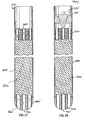
- Figure 18 is a section view of tool 900, another embodiment of the present invention.
- well fluid enters centre 905 and side 910 apertures at the bottom of the tool and is then filtered through woven fibre material 920 housed in the outer body 925.
- the well fluid passes through a baffle collar and into pipe thereabove through channels 930 formed at the upper end of the tool.
- the cement introduced into the annulus of the borehole by-passes the filter material 920 in the outer body 925.
- ports 935 formed in the tool above the channels 930 provide an exit path for cement.
- the ports 935 are sealed with a moveable sleeve allowing well fluid to pass from the filter material of the tool into the pipe thereabove.
- a plug is landed in the sleeve and urges the sleeve downward, thereby exposing the ports 935 which provide fluid communication between the inside of the tool and the borehole therearound. Because the cement travels through the open ports 935 during the cementing job, there is no need to pump the cement through the woven fibre material 920 in the outer body 925.
- Figures 19A , B and C are section views of an alternative embodiment of the present invention depicting a tool 950 for reducing surge during run-in and having a vortex separator for filtering sediment from well fluid.
- the vertex separator is well known in the art and operates by separating material based upon density.
- the fluid having a first density is separated from particles having a second density.
- fluid enters the nose portion 957 of the tool through apertures 955 formed on each side of the nose portion. Thereafter, the fluid travels through an annular area 960 formed between the outer body 962 and intermediate member 964. The path of the fluid is demonstrated by arrows 965.
- the fluid enters swirl tube 968 where it is directed to another annular area 966 formed between the inner wall of intermediate 964 and inner member 967.
- the fluid As the fluid travels downwards in annulus 966, it enters a third annular area 971 defined by the outer wall of the inner member 967 and an inner wall of an enclosure 972 open at a lower end and closed at an upper end.
- the fluid is filtered as it enters perforations 968 formed in inner member 967 and thereafter, filtered fluid travels upwards in inner member 967 through a baffle collar (not shown) and into a pipe thereabove.
- any sediment travelling with the fluid through annular area 966 is separated from the fluid as it enters inner member 967 through perforations 968.
- the sediment falls to the bottom of annular area 966 as illustrated in Figure 19 .
- Cement is thereafter carried downward through inner member 967, exiting centre aperture 969 through one-way check valve 970.
- Figure 20 is an alternative embodiment of the invention illustrating a tool 975 that includes a venturi jet bailer formed within.
- This embodiment is particularly effective for removing or bailing sediment encountered at any point in a wellbore.
- well fluid enters the tool through centre aperture 976 formed in nose portion 977.
- Flapper valve 978 prevents fluid from returning to the wellbore.
- fluid is filtered through apertures 980 formed along the length of two filtering members 982. Thereafter, filtered fluid travels into a pipe 988 above the tool through nozzle 984, in order to reduce pressure during run-in of the tool.
- the tool can be operated as a bailer by pressurising fluid above the tool and causing a stream of high velocity, low pressure fluid to travel downward through nozzle 984.
- the flow of fluid during the bailing operation is illustrated by arrows 985. Specifically, fluid travels through the nozzle and into diverter 986 where the fluid is directed out of the tool through ports 987 and into an annular area outside of the tool (not shown).
- a low pressure area is created adjacent the nozzle and a suction is thereby created in the lower portion of the tool. This suction causes any sediment present at the lower end of the tool to be urged into the tool through flapper valve 978.
- cementing is thereafter performed by pumping cement through the nozzle 984, into diverter 986 and into the annular area to be cemented (not shown) through ports 987.
Description
- The present invention provides a downhole surge pressure reduction apparatus for use in the oil well industry. More particularly, the invention provides a surge pressure reduction apparatus that is run into a well with a pipe string or other tubular to be cemented and facilitates the cementing by reducing surge pressure and inner well sediments during run-in.
- In the drilling of a hydrocarbon well, the borehole is typically lined with strings of pipe or tubulars (pipe or casing) to prevent the walls of the borehole from collapsing and to provide a reliable path for well production fluid, drilling mud and other fluids that are naturally present or that may be introduced into the well. Typically, after the well is drilled to a new depth, the drill bit and drill string are removed and a string of pipe is lowered into the well to a predetermined position whereby the top of the pipe is at about the same height as the bottom of the existing string of pipe (liner). In other instances, the new pipe string extends back to the surface of the well casing. In either case, the top of the pipe is fixed with a device such as a mechanical hanger. A column of cement is then pumped into the pipe or a smaller diameter run-in string and forced to the bottom of the borehole where it flows out of the pipe and flows upwards into an annulus defined by the borehole and pipe. The two principal functions of the cement between the pipe and the borehole are to restrict fluid movement between formations and to support the pipe.
- To save time and money, apparatus to facilitate cementing are often lowered into the borehole along with a hanger and pipe to be cemented. Cementing apparatus typically includes a number of different components made up at the surface prior to run-in. These include a tapered nose portion located at the downhole end of the pipe to facilitate insertion thereof into the borehole. A check valve at least partially seals the end of the tubular and prevents entry of well fluid during run-in while permitting cement to subsequently flow outwards. Another valve or plug typically located in a baffle collar above the cementing tool prevents the cement in the annulus from back flowing into the pipe. Components of the cementing apparatus are made of plastic, fibreglass or other disposable material that, like cement remaining in the pipe, can be drilled when the cementing is completed and the borehole is drilled to a new depth.
- There are problems associated with running a cementing apparatus into a well with a string of pipe. One such problem is surge pressure created as the pipe and cementing apparatus are lowered into the borehole filled with drilling mud or other well fluid. Because the end of the pipe is at least partially flow restricted, same of the well fluid is necessarily directed into the annular area between the borehole and the pipe. Rapid lowering of the pipe results in a corresponding increase or surge in pressure, at or below the pipe, generated by restricted fluid flow in the annulus. Surge pressure has many detrimental effects. For example, it can cause drilling fluid to be lost into the earth formation and it can weaken the exposed formation when the surge pressure in the borehole exceeds the formation pore pressure of the well. Additionally, surge pressure can cause a loss of cement to the formation during the cementing of the pipe due to formations that have become fractured by the surge pressure.
- One response to the surge pressure problem is to decrease the running speed of the pipe downhole in order to maintain the surge pressure at an acceptable level. An acceptable level would be a level at least where the drilling fluid pressure, including the surge pressure is less than the formation pore pressure to minimise the above detrimental effects. However, any reduction of surge pressure is beneficial because the more surge pressure is reduced, the faster the pipe can be run into the borehole and the more profitable a drilling operation becomes.
- The problem of surge pressure has been further addressed by the design of cementing apparatus that increases the flow path for drilling fluids through the pipe during run-in. In one such design, the check valve at the downhole end of the cementing apparatus is partially opened to flow during run-in to allow well fluid to enter the pipe and pressure to thereby be reduced. Various other paths are also provided higher in the apparatus to allow the well fluid to migrate upwards in the pipe during run-in. For example, baffle collars used at the top of cementing tools have been designed to permit the through flow of fluid during run-in by utilising valves that are held in a partially open position during run-in and then remotely closed later to prevent back flow of cement. While these designs have been somewhat successful, the flow of well fluid is still impeded by restricted passages. Subsequent closing of the valves in the cementing tool and the baffle collar is also problematic because of mechanical failures and contamination.
- Another problem encountered by prior art cementing apparatus relates to sediment, sand, drill cuttings and other particulates collected at the bottom of a newly drilled borehole and suspended within the drilling mud that fills the borehole prior to running-in a new pipe. Sediment at the borehole bottom becomes packed and prevents the pipe and cementing apparatus from being seated at the very bottom of the borehole after run-in. This misplacement of the cementing apparatus results in difficulties having the pipe in the well or at the wellhead. Also, the sediment below the cementing apparatus tends to be transported into the annulus with the cement where it has a detrimental effect on the quality of the cementing job. In those prior art designs that allow the drilling fluid to enter the pipe to reduce surge pressure, the fluid borne sediment can foul mechanical parts in the borehole and can subsequently contaminate the cement.
- There is a need therefore for a cementing apparatus that reduces surge pressure as it is run-into the well with a string of pipe. There is a further need, for a cementing apparatus that more effectively utilises the flow path of cement to transport well fluid and reduced pressure surge during run-in. There is a further need for a cementing apparatus that filters sediments and particles from well fluid during run-in.
According to a first aspect the present invention provides a cementing apparatus for cementing in a borehole comprising: - a filter apparatus comprising:
- a body, connectable prior to being run into the borehole in a tubular string to be cemented in the borehole;
- a filter member;
- a particulate retention portion for retaining filtered particles; and
- a fluid flow path directed through the retention portion and the filter member;
- characterised by a cement flow channel that substantially bypasses the filter member.
- Further aspects and preferred features are set out in claim 2.
- Some preferred embodiments of the invention will now be described by way of example only and with reference to the accompanying drawings, in which:
-
Figures 1A and B are section views of the tool of the present invention as it would appear in a borehole of a well; -
Figure 2 is a section view showing a first embodiment of a baffle collar for use with the tool; -
Figure 2A is an end view of the baffle collar ofFigure 2 , taken alonglines 2A-2A; -
Figure 3 is a section view showing a second embodiment of a baffle collar; -
Figure 4 is an end view of a centraliser located within the tool, taken along lines 4-4; -
Figure 5 is a section view showing a third embodiment of a baffle collar for use with the tool; -
Figure 6A is a section view of a plug at the end of a run-in string illustrating the flow of fluid through the plug during run-in; -
Figure 6B is an end view of the plug ofFigure 6A ; -
Figure 6C is a section view of the plug ofFigure 6A showing the flow paths of the plug sealed by a dart; -
Figure 6D is a section view of a plug at the end of a run-in string illustrating the flow of fluid through the plug during run-in; -
Figure 6E is an end view of the by-pass apertures illustrated inFigure 6D ; -
Figure 6F is a section view of the plug ofFigure 6D showing the flow paths of the plug sealed by a dart; -
Figure 7 is a section view showing a plug and dart assembly landed within a baffle collar and sealing channels formed therein; -
Figure 8 is an end view showing the nose portion of the tool, taken along lines 8-8; -
Figures 9A and B are enlarged views of the lower portion of the tool; -
Figures 10A and B depict an adjustment feature of the inner member of the tool; -
Figure 10C is an enlarged view of the inner member of the tool showing the relationship between an inner member and an inner sleeve disposed therein; -
Figures 11A and B are section views showing the tool with an additional sediment trapping member disposed therein; -
Figures 12A and B are section views showing the tool with an atmospheric chamber for evacuating sediment from the borehole; -
Figures 13A , B and C are section views showing the tool of the present invention with a remotely locatable, atmospheric chamber placed therein; -
Figures 14A and B are section views showing an alternative embodiment of the tool; -
Figures 15A and B are section views showing an alternative embodiment of the tool; -
Figures 16A and B are section views showing an alternative embodiment of the tool; -
Figure 17 is a section view showing an alternative embodiment of the tool; -
Figure 18 is a section view showing an alternative embodiment of the tool; -
Figures 19A , B and C are section views showing an alternative embodiment of the invention; and -
Figures 20A , B and C are section views showing an alternative embodiment of the invention. -
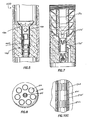
Figures 1A and B are section views showing the surge reduction andcementing tool 100 of the present invention.Figures 9A , B are enlarged views of the lower portion of the tool. In the Figures, the tool is depicted as it would appear after being inserted into aborehole 115. Thetool 100 generally includes anouter body 110, ainner member 135 disposed within theouter body 110, anose portion 120 and abaffle collar 125.Outer body 110 is preferably formed by the lower end of the pipe to be cemented in the borehole and thecementing tool 100 will typically be constructed and housed within the end of the pipe prior to being run-into the well. The terms "tubing," "tubular," "casing," "pipe" and "string" all relate to pipe used in a well or an operation within a well and are all used interchangeably herein. The term "pipe assembly" refers to a string of pipe, a hanger and a cementing tool all of which are run-into a borehole together on a run-in string of pipe. While the tool is shown in the Figures at the end of a tubular string, it will be understood that the tool described and claimed herein could also be inserted at any point in a string of tubulars. -
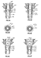
Nose portion 120 is installed at the lower end ofouter body 110 as depicted inFigure 1B to facilitate insertion of thetool 100 into theborehole 115 and to add strength and support to the lower end of theapparatus 100.Figure 8 is an end view of the downhole end of thetool 100 showing thenose portion 120 with a plurality of radially spacedapertures 122 formed therearound and acentre aperture 124 formed therein.Apertures 122 allow the inflow of fluid into thetool 100 during run-in andcentre aperture 124 allows cement to flow out into the borehole. - Centrally disposed within the
outer body 110 isinner member 135 providing a filtered path for well fluid during run-in and a path for cement into the borehole during the subsequent cementing job. At a lower end,inner member 135 is supported bynose portion 120. Specifically,support structure 121 formed withinnose portion 120 surrounds and supports the lower end ofinner member 135. Disposed between the lower end ofinner member 135 andnose portion 120 ischeck valve 140. The purpose ofvalve 140 is to restrict the flow of well fluid into the lower end ofinner member 135 while allowing the outward flow of cement from the end of inner member as will be decried herein. As shown inFigure 1B ,check valve 140 is preferably a spring-loaded type valve having a ball to effectively seal the end of a tubular and withstand pressure generated during run-in. However, any device capable of restricting fluid flow in a single direction can be utilized and all are within the scope of the invention as claimed. - Along the length of
inner portion 135 are a number ofcentralizers 145 providing additional support forinner member 135 and ensuring the inner member retains its position in the center ofouter body 110.Figure 4 is an end view of acentralizer 145 depicting its design and showing specifically its construction ofradial spokes 146 extending from theinner member 135 to the inside wall ofouter body 110, whereby fluid can freely pass though theannular area 155 formed betweeninner member 135 andouter body 110. Also visible inFigures 1A, 1B and4 are funnel-shapedtraps 147 designed to catch and retain sediment and particles that flow into theannular area 155, preventing them from falling back towards the bottom of the well. In the preferred embodiment, the sediment traps are nested at an upper end of eachcentralizer 145. Depending upon the length of theinner member 135, any number ofcentralizers 145 and sediment traps can be utilized in atool 100. -
Inner member 135 includes a inner portion formed therealong consisting of, in the preferred embodiment,perforations 160 extending therethrough to create a fluid path to the interior of theinner member 135. The perforations, while allowing the passage of fluid to reduce pressure surge, are also designed to prevent the passage of sediment or particles, thereby ensuring that the fluid traveling up the tool and into the pipe string above will be free of contaminants. The terms "filtering" and "separating" will be used interchangeably herein and both related to the removal, separation or isolation of any type of particle or other contaminate from the fluid passing through the tool. The size, shape and number of theperforations 160 are variable depending upon run-in speed and pressure surge generated during lowering of the pipe. Various material can be used to increase or define the inner properties of the inner member. For example, the inner member can be wrapped in or have installed in a membrane material made of corrosive resistant, polymer material and strengthened with a layer of braided metal wrapped therearound. Additionally, membrane material can be used to line the inside of the inner member. - The upper end of
inner member 135 is secured withinouter body 110 by adrillable cement ring 165 formed therearound.Inner member 135 terminates in aperforated cap 168 which can provide additional inner of fluids and, in an alternative embodiment, can also serve to catch a ball or other projectile used to actuate some device higher in the borehole. Between the upper end ofinner member 135 andbaffle collar 125 is aspace 180 that provides an accumulation point for cement being pumped into thetool 100. - At the upper end of
tool 100 is a funnel-shapedbaffle collar 125. In the preferred embodiment, the baffle collar provides a seat for a plug or other device which travels down the pipe behind a column of cement that is urged out the bottom oftool 100 and into theannulus 130 formed therearound. In the embodiment shown inFigure 1A , the baffle collar is held withinouter body 110 by cement or other drillable material. A mid-portion ofbaffle collar 125 includes by-pass holes 174 and by-pass channels 175 extending therefrom to provide fluid communication between thebaffle collar 125 andspace 180 therebelow. At a lower portion of thebaffle collar 125 is acheck valve 178 to prevent the inward flow of fluid into thebaffle collar 125 while allowing cement to flow outward into thespace 180 therebelow. During run-in, well fluid travels throughchannels 175.Figure 2 is an enlarged section view showing the various components of the baffle collar.Figure 2A is a section view showing the by-pass channels 175 and the placement of thecheck valve 178. -
Figure 7 illustrates a plug anddart assembly 190, having landed inbaffle collar 125 and sealed the fluid path of well fluid into the baffle collar through by-pass holes 174 and by-pass channels 175. In the preferred embodiment, after cement has been injected into the borehole and a dart has travelled down the run-in string and landed in the plug, the plug anddart assembly 190 are launched from the running string and urged downward in the pipe behind the column of cement that will be used to cement the pipe in theborehole 115. The plug anddart assembly 190 are designed to seat in thebaffle collar 125 where they also function to prevent subsequent back flow of cement into thebaffle collar 125 and the pipe (not shown) thereabove. -
Figure 3 is a section view showing an alternative embodiment of abaffle collar 300. In this embodiment, the upper portion of thebaffle collar 300 forms amale portion 301 withapertures 302 in fluid communication with by-pass channels 303.Male portion 301 is received by a plug and dart having a mating female portion formed therein. In this manner, theapertures 302 in the male portion of the baffle collar are covered and sealed by the female portion of the plug and dart assembly (not shown). -
Figure 5 illustrates a third embodiment of abaffle collar 400 for use in the tool of the present invention. In this embodiment, aflapper valve 405 is propped open during run-in to allow well fluid to pass through thebaffle collar 400 to relieve surge pressure. Once the pipe has been run in into the well, theflapper valve 405 is remotely closed by dropping aball 410 into aseat 415 which allows the spring-loadedflapper valve 405 to close. Thereafter, thebaffle collar 400 is sealed to the upper flow of fluid while theflapper valve 405 can be freely opened to allow the downward flow of cement. In this embodiment, the plug and dart assembly (not shown) includes wavy formations which mate with the wavy 420 formations formed in thebaffle collar 400. This embodiment is particularly useful anytime an object must be lowered or dropped into the cementing apparatus. Because it provides a clear path for a ball or other projectile into the cementing tool,baffle collar 400 is particularly useful with a remotely locatable portable atmospheric chamber described hereafter and illustrated inFigures 13A-C . -
Figures 6A-C illustrate aplug 194 and dart 200 at the end of a run-in string 185. The run-in string transports the pipe into the borehole, provides a fluid path from the well surface and extends at least some distance into the pipe to be cemented. The run-in string provides a flow path therethrough for well fluid during run-in and for cement as it passes from the well surface to the cementing tool at the end of the pipe. Anintermediate member 192, disposed within theplug 194 and having acentre aperture 197 therethrough, provides a seal for the nose of dart 200 (Figure 6C ) that lands in theplug 194 and seals the flow path therethrough. In order to increase the flow area throughintermediate member 192 yet retain the dimensional tolerances necessary for an effective seal between theplug 194 and thedart 200, a number of by-pass apertures 193 are formed around the perimeter of theintermediate member 192.Figure 6B is a section view of thenose portion 190 of theplug 194 clearly showing thecentre aperture 197 and by-pass apertures 193 ofintermediate member 192. In the preferred embodiment, the by-pass apertures 193 are elliptical in shape. -
Figure 6C is a section view showing theplug 194 withdart 200 seated therein.Centre aperture 197 of theintermediate member 192 is sealed by thedart nose 198 and the by-pass apertures 193 are sealed bydart fin 201 once theintermediate member 192 is urged downward in interior of theplug 194 by thedart 200. -
Figures 6D-F illustrate an alternative embodiment in which the by-pass apertures 220 of anintermediate member 222 are sealed when theintermediate member 222 is urged downward in the interior of theplug 225 by thedart 200, thereby creating a metal to metal seal between theplug surface 227 andouter diameter portion 226 ofintermediate member 222. - Generally, the tool of the present invention is used in the same manner as those of the prior art. After the well has been drilled to a new depth, the drill string and bit are removed from the well leaving the borehole at least partially filled with drilling fluid. Thereafter, pipe is lowered into the borehole having the cementing tool of the present invention at a downhole end and a run-in tool at an upper end. The entire assembly is run into the well at the end of a run-in string, a string of tubulars typically having a smaller diameter than the pipe and capable of providing an upward flow path for well fluid during run-in and a downward flow path for cement during the cementing operation.
- During run-in, the assembly minimises surge by passing well fluid through the radially spaced
apertures 122 of nose portion and into theouter body 110 where it is filtered as it passes into theinner member 135. While some of the fluid will travel up theannulus 130 formed between theouter body 110 and theborehole 115, thetool 100 is designed to permit a greater volume of fluid to enter the interior of the tubular being run into the well.Arrows 182 inFigure 1B illustrate the path of fluid as it travels betweenouter body 110 andinner member 135. As the run-in operation continues and the pipe continues downwards in the borehole, the fluid level rises withininner member 135 reaching and fillingspace 180 between the upper end of theinner member 135 and thebaffle collar 125. Prevented bycheck valve 178 from flowing into the bottom portion of thebaffle collar 125, the fluid enters thebaffle collar 125 through by-pass channels 175 and by-pass holes 174. Thereafter, the fluid can continue towards the surface of the well using the interior of the pipe and/or the inside diameter of the run-in string as a flow path. - With the
nose portion 120 of the tool at the bottom of the well and the upper end located either at the surface well head or near the end of the previously cemented pipe, the pipe may be hung in place, either at the well head or near the bottom of the preceding string through the remote actuation of a hanger, usually using a slip and cone mechanism to wedge the pipe in place. Cementing of the pipe in the borehole can then be accomplished by known methods, concluding with the seating of a plug assembly on or in a baffle collar. -
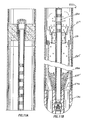
Figures 10A-C illustrate an alternative embodiment of thetool 500 wherein the perforations formed in aninner member 535 may be opened or closed depending upon well conditions or goals of the operator. In this embodiment, aninner sleeve 501 is located within theinner member 535. Theinner sleeve 501 hasperforations 502 formed therein and can be manipulated to cause alignment or misalignment with themating perforations 503 in theinner member 535. For example,Figure 10A illustrates theinner member 535 having aninner sleeve 501 which has been manipulated to block theperforations 503 of theinner member 535. Specifically, the perforations of the inner member and theinner sleeve Figure 10A at point "A" are misaligned, vertically blocking the flow of fluid therethrough. In contrast,Figure 10B at point "B" illustrates theperforations inner sleeve 501 andinner member 135 is more closely illustrated inFigure 10C , showing theperforations inner sleeve 501 andinner member 535 aligned. - Manipulation of the
inner sleeve 501 within theinner member 535 to align or misalignperforations tool 100 moving theinner sleeve 501 to cause itsperforations 503 to align or misalign with theperforations 502 ininner member 535. Alternatively, the manipulation can be performed with wireline. While the inner sleeve can be moved vertically in the embodiment depicted, it will be understood that theperforations - In operation, the
perforations perforations centre aperture 124 in thenose portion 120 of the tool, rather than through the perforations and into theannulus 130 between theinner member 135 and theouter body 110. -
Figures 11A and B show an alternative embodiment of a cementing tool 550 including a sediment trap 555 formed between aninner member 560 and anouter body 110. As depicted inFigure 11B , the sediment trap 555 is a cone-shaped structure having a tapered lower end extending from an upper end ofnose portion 120 and continuing upwards and outwards in a conical shape towardsouter body 110. Anannular area 565 is thereby formed between the outer wall of sediment trap 555 and the inside wall ofouter body 110 for the flow of well fluid during run-in. The direction of flow is illustrated byarrows 570 inFigure 11B . As the tool 550 is run into a well, well fluid and any sediment is routed throughannulus 565 and into the upper annulus 575 formed betweeninner member 560 andouter body 110. As the well fluid is filtered intoinner member 560,particles 580 and sediment removed byinner member 560 fall back towards the bottom of the well into the sediment trap 555 where they are retained as illustrated inFigure 11B . Because that portion ofinner member 565 extending through sediment trap 555 includes no inner perforations, contents of the sediment trap 555 remain separated from well fluid as it is filtered intoinner member 560. -
Figures 12A and B show an alternative embodiment of atool 600, including an apparatus for displacing and removing sediment from the bottom of the borehole, thereby allowing thetool 600 to be more accurately placed at the bottom of the borehole prior to cementing. In thetool 600 depicted inFigures 12A and B an annular area between theinner member 610 andouter body 110 is separated into an upper chamber 605 and alower chamber 615 by a donut-shaped member 620. The upper chamber 605, because it is isolated from well fluid and sealed at the well surface, forms an atmospheric chamber as thetool 600 is run into the borehole. Donut-shaped member 620 is axially movable withinouter body 110 but is fixed in place by afrangible member 625, the body of which is mounted in the interior ofinner member 610. Pins 621 between thefrangible member 625 and the donut-shaped member 620 hold the donut-shaped member in place. - After the
tool 600 has been run into the borehole, a ball or other projectile (not shown) is released from above thetool 600. Upon contact between the projectile and thefrangible member 625, the frangible member is fractured and the donut-shaped member 620 is released. The pressure differential between the upper 605 and lower 615 chambers of the tool causes the donut-shaped member 620 to move axially towards the well surface. This movement of the donut-shaped member 620 creates a suction in thelower chamber 615 of the tool which causes loose sediment (not shown) to be drawn into thelower chamber 615. In this manner, sediment is displaced from the borehole and the tool can be more accurately placed prior to a cementing job. -
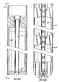
Figures 13A and B illustrate yet another embodiment of thetool 650, wherein a remotely locatable,atmospheric chamber 655 is placed in the interior ofinner member 660. As with the embodiment described inFigures 12A and B , the annular area betweeninner member 660 andouter body 110 is divided into an upper 665 and lower 670 chambers with a donut-shapedmember 675 dividing the two chambers. That portion of theinner member 680 extending through upper chamber 665 is not perforated but includes only a plurality of ports therearound. In this embodiment, pressure in the upper and lower chambers remain equalized during run-in of the tool into the borehole.Atmospheric chamber 655 is contained within atool 677. After run-in,atmospheric chamber tool 677 is lowered into the borehole by any known method including a separate running string or wireline. Theatmospheric chamber tool 677 lands on ashoulder 682 formed in the interior of theinner member 680 at which pointapertures 684 in theatmospheric chamber tool 677 andapertures 686 in theinner member 680 are aligned. In order to actuate theatmospheric chamber tool 850 and create a pressure differential between the upper 655 and lower 670 chambers, theatmospheric chamber tool 677 is urged downward until theapertures atmospheric chamber 655 and a pressure differential is created between the upper and lower chambers. The pressure differential causes the donut-shapedmember 825 to move axially towards the top of the tool because the hydrostatic pressure in the lower chamber is greater than the in the upper chamber. Therefore, a suction is created in the lower chamber 820 which evacuates loose sediment from the borehole and improves positioning of the tool in the borehole for the cementing job. - In another embodiment, a swabbing device (not shown) is run-into the pipe above the tool or may be run-into the
inner member 135 of thetool 100 to a location above theperforations 160. The swabbing device is then retracted in order to create a suction at the downhole end of the tool and urge sediment into the tool from the bottom of the borehole. The swabbing device is well known in the art and typically has a perimeter designed to allow fluid by-pass upon insertion into a tubular in one direction but expand to create a seal with the inside wall of the tubular when pulled in the other direction. In the present embodiment, the swabbing device is inserted into the well at the surface and run-into the well to a predetermined location after the pipe assembly has been run-into the well, but before cementing. The swabbing device is then pulled upwards in the borehole creating a suction that is transmitted to the downhole end of the tool, thereby evacuating sediment from the borehole. - In yet another embodiment, the
tool 100 is run-into the well with theperforations -
Figures 14A and B depict atool 700, another embodiment of the present invention. In this embodiment, theouter body 705 is perforated along its length to allow the flow of well fluid therethrough during run-in of the tool into a borehole. The flow of fluid is indicated by arrows 710. Upon filling the outer body, the well fluid passes through two one-way check valves 715a,b into a baffle collar and thereafter into a pipe thereabove (not shown). Thecheck valves 715 prevent fluid from returning into theouter body 705. In this embodiment, theinner member 720 is non-perforated and is isolated from the annulus between the inner member and outer body. In operation, theinner member 720 carries cement from its upper end to its lower end where the cement passes through a lower check valve 725 and into the annular area between the outer body and the borehole (not shown). -
Figures 15A and B are section views of another embodiment of the present invention depicting atool 750. In this embodiment, well fluid travels throughapertures 755 in thenose portion 760 of thetool 750 and into an annular area created between theinner member 765 and theouter body 770. From this annular area, fluid is filtered as it passes into perforated filtering members 775a,b which remove sand and sediment from the fluid before it passes throughcheck valves 780 to a baffle collar and into a pipe. The check valves prevent fluid from returning into the filtering members 775a,b. Like the embodiment ofFigure 14 , inner member 776 is a non-perforated member and provides a flow path for cement through a check valve at the downhole end of the tool and into the annulus to be cemented. -
Figures 16A and B are section views oftool 800, another embodiment of the present invention. During run-in of the tool into the borehole, well fluid enters a centre aperture 815 at a downhole end of aninner member 805 passing through aflapper valve 810 located in the centre aperture 815 which prevents well fluid from subsequently exiting the centre aperture. Well fluid is filtered as it passes from the inside of theinner member 805 to theouter body 825. The fluid continues upwards throughchannels 830 formed in the upper portion of the tool and into a pipe thereabove. Subsequently, cement is urged into the tool through thechannels 830 and travels within theouter body 825 to the bottom of the tool where it exits through one-way check valves 835. -
Figure 17 is a section view oftool 850, another embodiment of the present invention. In this embodiment, well fluid enters nose portion 855 of tool throughcentre aperture 860 andradial apertures 865 and is filtered through afilter medium 870 such as packed fibre material, which is housed within anouter body 875. After being filtered through the filter medium, the well fluid passes through the upper portion of the tool, throughchannels 880 formed in the upper portion of thetool 850 and then through a baffle collar and into a pipe thereabove. Thereafter, the cement is introduced into the tool through thechannels 880 and urged through the filter material to the bottom of the tool where it exitscentre 860 andradial apertures 865 into the annular area to be cemented. -
Figure 18 is a section view of tool 900, another embodiment of the present invention. Like the embodiment shown inFigure 17 , during run-in well fluid enterscentre 905 andside 910 apertures at the bottom of the tool and is then filtered through woven fibre material 920 housed in theouter body 925. The well fluid passes through a baffle collar and into pipe thereabove throughchannels 930 formed at the upper end of the tool. In this embodiment, unlike the embodiment described in relation toFigure 17 , the cement introduced into the annulus of the borehole by-passes the filter material 920 in theouter body 925. Specifically,ports 935 formed in the tool above thechannels 930 provide an exit path for cement. During run-in, theports 935 are sealed with a moveable sleeve allowing well fluid to pass from the filter material of the tool into the pipe thereabove. After the tool is run into the well, a plug is landed in the sleeve and urges the sleeve downward, thereby exposing theports 935 which provide fluid communication between the inside of the tool and the borehole therearound. Because the cement travels through theopen ports 935 during the cementing job, there is no need to pump the cement through the woven fibre material 920 in theouter body 925. -
Figures 19A , B and C are section views of an alternative embodiment of the present invention depicting atool 950 for reducing surge during run-in and having a vortex separator for filtering sediment from well fluid. The vertex separator is well known in the art and operates by separating material based upon density. In the present invention, the fluid having a first density is separated from particles having a second density. In this embodiment, fluid enters thenose portion 957 of the tool throughapertures 955 formed on each side of the nose portion. Thereafter, the fluid travels through anannular area 960 formed between the outer body 962 andintermediate member 964. The path of the fluid is demonstrated byarrows 965. At the upper end ofannulus 960, the fluid entersswirl tube 968 where it is directed to anotherannular area 966 formed between the inner wall of intermediate 964 andinner member 967. As the fluid travels downwards inannulus 966, it enters a thirdannular area 971 defined by the outer wall of theinner member 967 and an inner wall of anenclosure 972 open at a lower end and closed at an upper end. The fluid is filtered as it entersperforations 968 formed ininner member 967 and thereafter, filtered fluid travels upwards ininner member 967 through a baffle collar (not shown) and into a pipe thereabove. In the embodiment shown inFigure 19B , any sediment travelling with the fluid throughannular area 966 is separated from the fluid as it entersinner member 967 throughperforations 968. The sediment falls to the bottom ofannular area 966 as illustrated inFigure 19 . Cement is thereafter carried downward throughinner member 967, exitingcentre aperture 969 through one-way check valve 970. -
Figure 20 is an alternative embodiment of the invention illustrating atool 975 that includes a venturi jet bailer formed within. This embodiment is particularly effective for removing or bailing sediment encountered at any point in a wellbore. During run-in, well fluid enters the tool throughcentre aperture 976 formed innose portion 977.Flapper valve 978 prevents fluid from returning to the wellbore. After entering the tool, fluid is filtered throughapertures 980 formed along the length of two filteringmembers 982. Thereafter, filtered fluid travels into apipe 988 above the tool throughnozzle 984, in order to reduce pressure during run-in of the tool. - Wherever sediment is encountered in the wellbore, the tool can be operated as a bailer by pressurising fluid above the tool and causing a stream of high velocity, low pressure fluid to travel downward through
nozzle 984. The flow of fluid during the bailing operation is illustrated byarrows 985. Specifically, fluid travels through the nozzle and intodiverter 986 where the fluid is directed out of the tool throughports 987 and into an annular area outside of the tool (not shown). As the high velocity fluid is channelled throughnozzle 984, a low pressure area is created adjacent the nozzle and a suction is thereby created in the lower portion of the tool. This suction causes any sediment present at the lower end of the tool to be urged into the tool throughflapper valve 978. The sediment is prevented from falling back into the wellbore by the flapper valve and remains within the interior of the tool. Cementing is thereafter performed by pumping cement through thenozzle 984, intodiverter 986 and into the annular area to be cemented (not shown) throughports 987. - While foregoing is directed to the preferred embodiment of the present invention, other and further embodiments of the invention may be devised without departing from the basic scope thereof, and the scope thereof is determined by the claims that follow.
Claims (2)
- A cementing apparatus for cementing in a borehole comprising:a filter apparatus, the filter apparatus comprising:a body (105), connectable prior to being run into the borehole in a tubular string to be cemented in the borehole;a filter member (135);a particulate retention portion (147) for retaining filtered particles; anda fluid flow path (182) directed through the retention portion and the filter member;characterised by a cement flow channel that substantially bypasses the filter member.
- A method of cementing in a borehole by running a tubular string therein comprising the steps of:attaching a filtering apparatus in the tubular string, the filtering apparatus comprising a filter member (135), a particulate retention portion (147) and a fluid flow path (182) directed through the retention portion and the filter member; andrunning the tubular string into the borehole, thereby causing the borehole fluid to be filtered through the filtering apparatus;characterised by passing cement through a cement flow channel that substantially bypasses the filter member.
Applications Claiming Priority (3)
| Application Number | Priority Date | Filing Date | Title |
|---|---|---|---|
| US524180 | 2000-03-13 | ||
| US09/524,180 US6571869B1 (en) | 2000-03-13 | 2000-03-13 | Downhole surge pressure reduction and filtering apparatus |
| EP01910056A EP1264073B1 (en) | 2000-03-13 | 2001-03-12 | Downhole surge pressure reduction and filtering apparatus |
Related Parent Applications (1)
| Application Number | Title | Priority Date | Filing Date |
|---|---|---|---|
| EP01910056A Division EP1264073B1 (en) | 2000-03-13 | 2001-03-12 | Downhole surge pressure reduction and filtering apparatus |
Publications (3)
| Publication Number | Publication Date |
|---|---|
| EP1510650A2 EP1510650A2 (en) | 2005-03-02 |
| EP1510650A3 EP1510650A3 (en) | 2005-05-25 |
| EP1510650B1 true EP1510650B1 (en) | 2008-04-30 |
Family
ID=24088098
Family Applications (2)
| Application Number | Title | Priority Date | Filing Date |
|---|---|---|---|
| EP01910056A Expired - Lifetime EP1264073B1 (en) | 2000-03-13 | 2001-03-12 | Downhole surge pressure reduction and filtering apparatus |
| EP04105609A Expired - Lifetime EP1510650B1 (en) | 2000-03-13 | 2001-03-12 | Downhole surge pressure reduction and filtering apparatus |
Family Applications Before (1)
| Application Number | Title | Priority Date | Filing Date |
|---|---|---|---|
| EP01910056A Expired - Lifetime EP1264073B1 (en) | 2000-03-13 | 2001-03-12 | Downhole surge pressure reduction and filtering apparatus |
Country Status (7)
| Country | Link |
|---|---|
| US (5) | US6571869B1 (en) |
| EP (2) | EP1264073B1 (en) |
| AU (2) | AU3763901A (en) |
| CA (1) | CA2400973C (en) |
| DE (2) | DE60133841D1 (en) |
| NO (2) | NO322170B1 (en) |
| WO (1) | WO2001069036A1 (en) |
Families Citing this family (42)
| Publication number | Priority date | Publication date | Assignee | Title |
|---|---|---|---|---|
| US6571869B1 (en) * | 2000-03-13 | 2003-06-03 | Weatherford/Lamb, Inc. | Downhole surge pressure reduction and filtering apparatus |
| CA2412072C (en) | 2001-11-19 | 2012-06-19 | Packers Plus Energy Services Inc. | Method and apparatus for wellbore fluid treatment |
| US8955619B2 (en) * | 2002-05-28 | 2015-02-17 | Weatherford/Lamb, Inc. | Managed pressure drilling |
| US8167047B2 (en) | 2002-08-21 | 2012-05-01 | Packers Plus Energy Services Inc. | Method and apparatus for wellbore fluid treatment |
| US7069991B2 (en) * | 2003-01-09 | 2006-07-04 | Weatherford/Lamb, Inc. | Method and apparatus for surge pressure reduction in a tool with fluid motivator |
| US7182135B2 (en) * | 2003-11-14 | 2007-02-27 | Halliburton Energy Services, Inc. | Plug systems and methods for using plugs in subterranean formations |
| US7243740B2 (en) * | 2003-12-05 | 2007-07-17 | Pathfinder Energy Services, Inc. | Filter assembly having a bypass passageway and method |
| US20060213667A1 (en) * | 2005-03-28 | 2006-09-28 | Mashburn Benny D | Screen apparatus and method |
| US7836973B2 (en) | 2005-10-20 | 2010-11-23 | Weatherford/Lamb, Inc. | Annulus pressure control drilling systems and methods |
| US20070246224A1 (en) * | 2006-04-24 | 2007-10-25 | Christiaan Krauss | Offset valve system for downhole drillable equipment |
| US7980313B2 (en) * | 2007-07-05 | 2011-07-19 | Gulfstream Services, Inc. | Method and apparatus for catching a pump-down plug or ball |
| CA2621041C (en) * | 2007-09-20 | 2014-04-22 | Source Energy Tool Services Inc. | Enclosed circulation tool for a well |
| US8276665B2 (en) * | 2008-04-03 | 2012-10-02 | Halliburton Energy Services Inc. | Plug release apparatus |
| US8757273B2 (en) | 2008-04-29 | 2014-06-24 | Packers Plus Energy Services Inc. | Downhole sub with hydraulically actuable sleeve valve |
| US20100288492A1 (en) * | 2009-05-18 | 2010-11-18 | Blackman Michael J | Intelligent Debris Removal Tool |
| WO2011153098A1 (en) | 2010-06-01 | 2011-12-08 | Smith International, Inc. | Liner hanger fluid diverter tool and related methods |
| GB2485394B (en) * | 2010-11-12 | 2016-08-10 | M-I Drilling Fluids U K Ltd | Modular tool for wellbore cleaning |
| US8746340B2 (en) * | 2011-01-06 | 2014-06-10 | Benny Donald Mashburn | Fish-thru screen apparatus and method |
| US8561695B2 (en) * | 2011-04-11 | 2013-10-22 | Chevron U.S.A. Inc. | Apparatus and method for testing solids production in a wellbore |
| US9010414B2 (en) | 2011-11-30 | 2015-04-21 | Baker Hughes Incorporated | Differential pressure control device for packer tieback extension or polished bore receptacle |
| US8881802B2 (en) | 2011-11-30 | 2014-11-11 | Baker Hughes Incorporated | Debris barrier for packer setting sleeve |
| US9695675B2 (en) | 2014-01-03 | 2017-07-04 | Weatherford Technology Holdings, Llc | High-rate injection screen assembly with checkable ports |
| WO2015108512A1 (en) * | 2014-01-15 | 2015-07-23 | Halliburton Energy Services, Inc. | Well diverter assembly with substantially pressure balanced annular seal device |
| US9593536B2 (en) * | 2014-05-09 | 2017-03-14 | Reelwell, AS | Casing drilling system and method |
| US9371716B2 (en) * | 2014-05-09 | 2016-06-21 | Chevron U.S.A. Inc. | Self-extendable hydraulic wellbore cleaning tool |
| US10280713B2 (en) | 2014-10-31 | 2019-05-07 | Spoked Solutions LLC | Systems and methods for managing debris in a well |
| US10100615B2 (en) * | 2014-10-31 | 2018-10-16 | Spoked Solutions LLC | Systems and methods for managing debris in a well |
| WO2017003445A1 (en) | 2015-06-30 | 2017-01-05 | Halliburton Energy Services, Inc. | Flushing filter |
| GB2554297B (en) | 2015-07-14 | 2021-06-09 | Halliburton Energy Services Inc | Self-cleaning filter |
| CA2989999C (en) | 2015-07-27 | 2019-07-09 | Halliburton Energy Services, Inc. | Centrifugal particle accumulator and filter |
| JP2017033457A (en) * | 2015-08-05 | 2017-02-09 | 富士通株式会社 | Scheduling support method, information processor, and scheduling support program |
| US9752409B2 (en) | 2016-01-21 | 2017-09-05 | Completions Research Ag | Multistage fracturing system with electronic counting system |
| US10648256B2 (en) | 2016-03-04 | 2020-05-12 | Cambre Allen Romero | Diffuser assembly |
| US10053960B2 (en) | 2016-03-04 | 2018-08-21 | Downhole Rental Tools, LLC | Downhole diffuser assembly |
| US20170268309A1 (en) * | 2016-03-18 | 2017-09-21 | Baker Hughes Incorporated | Actuation configuration and method |
| CA3031629C (en) | 2016-09-13 | 2021-12-28 | Halliburton Energy Services, Inc. | Sand fall-back prevention tools |
| US10677019B2 (en) | 2018-08-20 | 2020-06-09 | Cambre Allen Romero | Diffuser assembly with vibration feature |
| US10605064B1 (en) * | 2019-06-11 | 2020-03-31 | Wellworx Energy Solutions Llc | Sand and solids bypass separator |
| US11434723B2 (en) * | 2020-01-24 | 2022-09-06 | Odessa Separator, Inc. | Sand lift tool, system and method |
| US10910478B1 (en) * | 2020-03-04 | 2021-02-02 | Shuming Xu | Metal-oxide-semiconductor field-effect transistor having enhanced high-frequency performance |
| CN113294123B (en) * | 2021-05-20 | 2022-02-25 | 黑龙江博淮石油设备科技有限公司 | Integrated device is handled to special quantum wax dirt in oil field |
| CN117642147A (en) * | 2021-06-04 | 2024-03-01 | 联合利华知识产权控股有限公司 | Method for providing high SPF to a local surface of a body |
Family Cites Families (38)
| Publication number | Priority date | Publication date | Assignee | Title |
|---|---|---|---|---|
| US436889A (en) * | 1890-09-23 | Point for well-sinking machines | ||
| US3123517A (en) * | 1964-03-03 | Conduit string | ||
| US1502696A (en) * | 1922-08-03 | 1924-07-29 | Thomson Alexander | Wash-pipe valve |
| US1572022A (en) * | 1924-04-28 | 1926-02-09 | De Witt C King | Trap for oil-well pumps |
| US2214550A (en) * | 1928-08-24 | 1940-09-10 | Houston Engineers Inc | Testing device for wells |
| US1964264A (en) * | 1929-12-21 | 1934-06-26 | James O Mack | Apparatus for cleaning wells |
| US1839044A (en) * | 1930-01-16 | 1931-12-29 | Thomas B Minyard | Gravel well screen |
| US1915136A (en) * | 1931-11-20 | 1933-06-20 | Share Barnett | Well point |
| US2090545A (en) * | 1935-06-17 | 1937-08-17 | Thomas F Moore | Well-point |
| US2190404A (en) * | 1938-03-07 | 1940-02-13 | James I Hastings | Combination taper square |
| US2190407A (en) * | 1938-12-19 | 1940-02-13 | King Clifford Clay | Sand pump |
| US2340481A (en) | 1940-06-25 | 1944-02-01 | Ralph B Lloyd | Apparatus for starting flow in wells |
| US2291371A (en) * | 1940-08-03 | 1942-07-28 | Security Engineering Co Inc | Method and apparatus for cementing liners in wells |
| US2335578A (en) * | 1941-03-03 | 1943-11-30 | Dow Chemical Co | Well casing |
| US2781774A (en) * | 1951-07-03 | 1957-02-19 | Baker Oil Tools Inc | Valve apparatus for automatically filling well conduits |
| US2978033A (en) * | 1957-04-01 | 1961-04-04 | Jersey Prod Res Co | Drillable prepacked sand control liner |
| US3001585A (en) * | 1957-12-17 | 1961-09-26 | Texaco Inc | Deep well cementing apparatus |
| US3166132A (en) * | 1961-06-22 | 1965-01-19 | Halliburton Co | Grouting tool |
| US3302722A (en) * | 1963-10-25 | 1967-02-07 | Sr Milton H Madeley | Wire line retrievable wash pipe bottom hole assembly |
| US3277962A (en) * | 1963-11-29 | 1966-10-11 | Pan American Petroleum Corp | Gravel packing method |
| US3664421A (en) | 1970-09-18 | 1972-05-23 | Schlumberger Technology Corp | Methods for inhibiting the production of loose formation materials |
| US3760878A (en) | 1972-03-16 | 1973-09-25 | Amoco Prod Co | Perforations washing tool |
| US3895678A (en) | 1974-07-08 | 1975-07-22 | Dresser Ind | Sealer ball catcher and method of use thereof |
| US4190113A (en) * | 1978-07-27 | 1980-02-26 | Harrison Wayne O | Well cleanout tool |
| DE3309031C2 (en) | 1983-03-14 | 1986-07-31 | Turkmenskij naučno-issledovatel'skij geologorasvedočnyj institut, Ašchabad | Drilling rig for earth drilling and testing of groundwater horizons |
| US4760884A (en) | 1986-09-16 | 1988-08-02 | Halliburton Company | Air chamber actuated dual tubing release assembly |
| US4856590A (en) | 1986-11-28 | 1989-08-15 | Mike Caillier | Process for washing through filter media in a production zone with a pre-packed screen and coil tubing |
| US4791992A (en) * | 1987-08-18 | 1988-12-20 | Dresser Industries, Inc. | Hydraulically operated and released isolation packer |
| US5366009A (en) | 1991-03-12 | 1994-11-22 | Atlantic Richfield Company | Gravel pack well completions with auger-liner |
| US5234055A (en) * | 1991-10-10 | 1993-08-10 | Atlantic Richfield Company | Wellbore pressure differential control for gravel pack screen |
| US5377750A (en) | 1992-07-29 | 1995-01-03 | Halliburton Company | Sand screen completion |
| US5295537A (en) * | 1992-08-04 | 1994-03-22 | Trainer C W | Sand separating, producing-well accessory |
| US5327960A (en) * | 1992-11-24 | 1994-07-12 | Atlantic Richfield Company | Gravel pack installations for wells |
| US5526884A (en) * | 1995-05-05 | 1996-06-18 | Baker Hughes Incorporated | Downhole tool release mechanism |
| US5960881A (en) | 1997-04-22 | 1999-10-05 | Jerry P. Allamon | Downhole surge pressure reduction system and method of use |
| GB2338009B (en) | 1998-06-04 | 2000-06-21 | Philip Head | A method of installing the casing in a well and apparatus therefor |
| US6571869B1 (en) | 2000-03-13 | 2003-06-03 | Weatherford/Lamb, Inc. | Downhole surge pressure reduction and filtering apparatus |
| US6269879B1 (en) * | 2000-03-20 | 2001-08-07 | Harper Boyd | Sleeve liner for wireline entry sub assembly |
-
2000
- 2000-03-13 US US09/524,180 patent/US6571869B1/en not_active Expired - Lifetime
-
2001
- 2001-03-12 AU AU3763901A patent/AU3763901A/en active Pending
- 2001-03-12 EP EP01910056A patent/EP1264073B1/en not_active Expired - Lifetime
- 2001-03-12 DE DE60133841T patent/DE60133841D1/en not_active Expired - Lifetime
- 2001-03-12 WO PCT/GB2001/001070 patent/WO2001069036A1/en active IP Right Grant
- 2001-03-12 AU AU2001237639A patent/AU2001237639B2/en not_active Ceased
- 2001-03-12 CA CA002400973A patent/CA2400973C/en not_active Expired - Lifetime
- 2001-03-12 DE DE60109142T patent/DE60109142D1/en not_active Expired - Fee Related
- 2001-03-12 EP EP04105609A patent/EP1510650B1/en not_active Expired - Lifetime
-
2002
- 2002-08-21 NO NO20023965A patent/NO322170B1/en not_active IP Right Cessation
- 2002-12-20 US US10/324,412 patent/US6755252B2/en not_active Expired - Lifetime
-
2004
- 2004-06-08 US US10/863,165 patent/US6966375B2/en not_active Expired - Lifetime
-
2005
- 2005-10-07 US US11/245,494 patent/US7270181B2/en not_active Expired - Lifetime
-
2006
- 2006-07-17 NO NO20063296A patent/NO332253B1/en not_active IP Right Cessation
-
2007
- 2007-07-16 US US11/778,258 patent/US7487831B2/en not_active Expired - Fee Related
Also Published As
| Publication number | Publication date |
|---|---|
| EP1264073B1 (en) | 2005-03-02 |
| WO2001069036A1 (en) | 2001-09-20 |
| EP1510650A3 (en) | 2005-05-25 |
| NO20023965L (en) | 2002-10-09 |
| US20060032634A1 (en) | 2006-02-16 |
| US7270181B2 (en) | 2007-09-18 |
| US20030089505A1 (en) | 2003-05-15 |
| DE60133841D1 (en) | 2008-06-12 |
| CA2400973C (en) | 2006-09-26 |
| EP1510650A2 (en) | 2005-03-02 |
| EP1264073A1 (en) | 2002-12-11 |
| US20080011480A1 (en) | 2008-01-17 |
| AU2001237639B2 (en) | 2005-12-01 |
| US6571869B1 (en) | 2003-06-03 |
| US6755252B2 (en) | 2004-06-29 |
| US20040251023A1 (en) | 2004-12-16 |
| AU3763901A (en) | 2001-09-24 |
| NO332253B1 (en) | 2012-08-06 |
| CA2400973A1 (en) | 2001-09-20 |
| NO20063296L (en) | 2002-10-09 |
| NO20023965D0 (en) | 2002-08-21 |
| DE60109142D1 (en) | 2005-04-07 |
| NO322170B1 (en) | 2006-08-21 |
| US7487831B2 (en) | 2009-02-10 |
| US6966375B2 (en) | 2005-11-22 |
Similar Documents
| Publication | Publication Date | Title |
|---|---|---|
| EP1510650B1 (en) | Downhole surge pressure reduction and filtering apparatus | |
| AU2001237639A1 (en) | Downhole surge pressure reduction and filtering apparatus | |
| US10711588B2 (en) | Systems and apparatuses for separating wellbore fluids and solids during production | |
| US10465484B2 (en) | Gravel packing system and method | |
| US4192375A (en) | Gravel-packing tool assembly | |
| RU2578064C2 (en) | Liner cementing assembly and nose-to-toe installation of gravel filter per one run | |
| US7520326B1 (en) | Method and apparatus for performing down hole sand and gravel fracture packing operations | |
| US20100212895A1 (en) | Screen Flow Equalization System | |
| EP3194708B1 (en) | Fast-setting retrievable slim-hole test packer and method of use | |
| CN111886398B (en) | Separating gas and liquid in a wellbore | |
| AU2007200592C1 (en) | Downhole Surge Pressure Reduction and Filtering Apparatus | |
| US20190301272A1 (en) | Systems for downhole separation of gases from liquids having interchangeable fluid conductors | |
| AU2005225147B2 (en) | Downhole Surge Pressure Reduction and Filtering Apparatus | |
| CA2571670C (en) | Downhole surge pressure reduction and filtering apparatus | |
| CA2526837C (en) | Downhole surge pressure reduction and filtering apparatus | |
| USRE42030E1 (en) | Critical velocity reduction in a gas well | |
| WO2014198887A1 (en) | A completion method and a downhole system | |
| US9127522B2 (en) | Method and apparatus for sealing an annulus of a wellbore | |
| WO2016156187A1 (en) | Method and system for operating a gas well |
Legal Events
| Date | Code | Title | Description |
|---|---|---|---|
| PUAI | Public reference made under article 153(3) epc to a published international application that has entered the european phase |
Free format text: ORIGINAL CODE: 0009012 |
|
| 17P | Request for examination filed |
Effective date: 20041115 |
|
| AC | Divisional application: reference to earlier application |
Ref document number: 1264073 Country of ref document: EP Kind code of ref document: P |
|
| AK | Designated contracting states |
Kind code of ref document: A2 Designated state(s): DE FR GB NL |
|
| PUAL | Search report despatched |
Free format text: ORIGINAL CODE: 0009013 |
|
| AK | Designated contracting states |
Kind code of ref document: A3 Designated state(s): DE FR GB NL |
|
| AKX | Designation fees paid |
Designated state(s): DE FR GB NL |
|
| 17Q | First examination report despatched |
Effective date: 20051220 |
|
| RIN1 | Information on inventor provided before grant (corrected) |
Inventor name: PLUCHEK, CLAYTON, STANLEY Inventor name: HAUGEN, DAVID, MICHAEL Inventor name: GIROUX, RICHARD, LEE Inventor name: SCOTT, THAD JOSEPH Inventor name: PEDERSEN, GERALD, DEAN |
|
| GRAP | Despatch of communication of intention to grant a patent |
Free format text: ORIGINAL CODE: EPIDOSNIGR1 |
|
| GRAS | Grant fee paid |
Free format text: ORIGINAL CODE: EPIDOSNIGR3 |
|
| GRAA | (expected) grant |
Free format text: ORIGINAL CODE: 0009210 |
|
| AC | Divisional application: reference to earlier application |
Ref document number: 1264073 Country of ref document: EP Kind code of ref document: P |
|
| AK | Designated contracting states |
Kind code of ref document: B1 Designated state(s): DE FR GB NL |
|
| REG | Reference to a national code |
Ref country code: GB Ref legal event code: FG4D |
|
| REF | Corresponds to: |
Ref document number: 60133841 Country of ref document: DE Date of ref document: 20080612 Kind code of ref document: P |
|
| EN | Fr: translation not filed | ||
| PLBE | No opposition filed within time limit |
Free format text: ORIGINAL CODE: 0009261 |
|
| STAA | Information on the status of an ep patent application or granted ep patent |
Free format text: STATUS: NO OPPOSITION FILED WITHIN TIME LIMIT |
|
| 26N | No opposition filed |
Effective date: 20090202 |
|
| PG25 | Lapsed in a contracting state [announced via postgrant information from national office to epo] |
Ref country code: FR Free format text: LAPSE BECAUSE OF FAILURE TO SUBMIT A TRANSLATION OF THE DESCRIPTION OR TO PAY THE FEE WITHIN THE PRESCRIBED TIME-LIMIT Effective date: 20090227 Ref country code: DE Free format text: LAPSE BECAUSE OF FAILURE TO SUBMIT A TRANSLATION OF THE DESCRIPTION OR TO PAY THE FEE WITHIN THE PRESCRIBED TIME-LIMIT Effective date: 20080731 |
|
| REG | Reference to a national code |
Ref country code: NL Ref legal event code: SD Effective date: 20150318 |
|
| REG | Reference to a national code |
Ref country code: GB Ref legal event code: 732E Free format text: REGISTERED BETWEEN 20151022 AND 20151028 |
|
| PGFP | Annual fee paid to national office [announced via postgrant information from national office to epo] |
Ref country code: NL Payment date: 20180314 Year of fee payment: 18 |
|
| REG | Reference to a national code |
Ref country code: NL Ref legal event code: MM Effective date: 20190401 |
|
| PG25 | Lapsed in a contracting state [announced via postgrant information from national office to epo] |
Ref country code: NL Free format text: LAPSE BECAUSE OF NON-PAYMENT OF DUE FEES Effective date: 20190401 |
|
| PGFP | Annual fee paid to national office [announced via postgrant information from national office to epo] |
Ref country code: GB Payment date: 20200102 Year of fee payment: 20 |
|
| REG | Reference to a national code |
Ref country code: GB Ref legal event code: 732E Free format text: REGISTERED BETWEEN 20200813 AND 20200819 |
|
| REG | Reference to a national code |
Ref country code: GB Ref legal event code: 732E Free format text: REGISTERED BETWEEN 20201126 AND 20201202 |
|
| REG | Reference to a national code |
Ref country code: GB Ref legal event code: 732E Free format text: REGISTERED BETWEEN 20210225 AND 20210303 |
|
| REG | Reference to a national code |
Ref country code: GB Ref legal event code: PE20 Expiry date: 20210311 |
|
| PG25 | Lapsed in a contracting state [announced via postgrant information from national office to epo] |
Ref country code: GB Free format text: LAPSE BECAUSE OF EXPIRATION OF PROTECTION Effective date: 20210311 |