EP1513232A1 - Laser device and method for operating the laser device - Google Patents
Laser device and method for operating the laser device Download PDFInfo
- Publication number
- EP1513232A1 EP1513232A1 EP03020178A EP03020178A EP1513232A1 EP 1513232 A1 EP1513232 A1 EP 1513232A1 EP 03020178 A EP03020178 A EP 03020178A EP 03020178 A EP03020178 A EP 03020178A EP 1513232 A1 EP1513232 A1 EP 1513232A1
- Authority
- EP
- European Patent Office
- Prior art keywords
- laser device
- laser
- solid
- active region
- state laser
- Prior art date
- Legal status (The legal status is an assumption and is not a legal conclusion. Google has not performed a legal analysis and makes no representation as to the accuracy of the status listed.)
- Withdrawn
Links
Images


Classifications
-
- H—ELECTRICITY
- H01—ELECTRIC ELEMENTS
- H01S—DEVICES USING THE PROCESS OF LIGHT AMPLIFICATION BY STIMULATED EMISSION OF RADIATION [LASER] TO AMPLIFY OR GENERATE LIGHT; DEVICES USING STIMULATED EMISSION OF ELECTROMAGNETIC RADIATION IN WAVE RANGES OTHER THAN OPTICAL
- H01S3/00—Lasers, i.e. devices using stimulated emission of electromagnetic radiation in the infrared, visible or ultraviolet wave range
- H01S3/09—Processes or apparatus for excitation, e.g. pumping
- H01S3/091—Processes or apparatus for excitation, e.g. pumping using optical pumping
- H01S3/094—Processes or apparatus for excitation, e.g. pumping using optical pumping by coherent light
- H01S3/0941—Processes or apparatus for excitation, e.g. pumping using optical pumping by coherent light of a laser diode
-
- H—ELECTRICITY
- H01—ELECTRIC ELEMENTS
- H01S—DEVICES USING THE PROCESS OF LIGHT AMPLIFICATION BY STIMULATED EMISSION OF RADIATION [LASER] TO AMPLIFY OR GENERATE LIGHT; DEVICES USING STIMULATED EMISSION OF ELECTROMAGNETIC RADIATION IN WAVE RANGES OTHER THAN OPTICAL
- H01S3/00—Lasers, i.e. devices using stimulated emission of electromagnetic radiation in the infrared, visible or ultraviolet wave range
- H01S3/02—Constructional details
- H01S3/04—Arrangements for thermal management
- H01S3/042—Arrangements for thermal management for solid state lasers
-
- H—ELECTRICITY
- H01—ELECTRIC ELEMENTS
- H01S—DEVICES USING THE PROCESS OF LIGHT AMPLIFICATION BY STIMULATED EMISSION OF RADIATION [LASER] TO AMPLIFY OR GENERATE LIGHT; DEVICES USING STIMULATED EMISSION OF ELECTROMAGNETIC RADIATION IN WAVE RANGES OTHER THAN OPTICAL
- H01S3/00—Lasers, i.e. devices using stimulated emission of electromagnetic radiation in the infrared, visible or ultraviolet wave range
- H01S3/23—Arrangements of two or more lasers not provided for in groups H01S3/02 - H01S3/22, e.g. tandem arrangements of separate active media
- H01S3/2383—Parallel arrangements
Definitions
- the present invention relates to a laser device comprising at least one solid-state laser unit with at least one active Area in which laser radiation can be generated, as well at least one semiconductor laser device, the pumping light for the optical pumps of the at least one active region of the can generate at least one solid-state laser unit.
- the present invention relates to a method for operating a Such a laser device according to the preamble of the claim 18th
- this slab consists of three Layers, namely a middle active area, the for example, consists of Nd: YAG, as well as two outer Layers sandwiching the middle layer, wherein these two outer layers, for example, undoped YAG can exist.
- a middle active area the for example, consists of Nd: YAG
- two outer Layers sandwiching the middle layer wherein these two outer layers, for example, undoped YAG can exist.
- the surrounded Layers of undoped material can be used for example for Pump light bundling serve.
- the surrounding ones ensure undoped layers that in the pumping light source facing Edge areas of the active layer no losses on exit from Edge areas occur because of the edges of the active Layer the outer layers connect seamlessly.
- the problem underlying the present invention is the Creation of a laser device of the type mentioned, in which with simple means a comparatively small divergence of the laser device generated laser beam can be achieved. Furthermore, a method for operating the aforementioned type be given, with a laser beam with comparatively small divergence can be generated.
- the laser device so is formed that the pump light during operation of the Laser device in the at least one active area a Plural of spaced apart optically pumped channels can produce, in each of which a partial beam of the Laser radiation can be generated.
- a Plural of spaced apart optically pumped channels can produce, in each of which a partial beam of the Laser radiation can be generated.
- the laser device according to the invention otherwise be comparatively simple. Especially also the active area and the resonator do not have to be very special be structured to influence the fashion spectrum of the To take laser device.
- the laser device means for the introduction of the at least one Semiconductor laser device generated pump light in the at least an active region of the at least one solid-state laser unit having.
- These agents may according to claim 3 comprise lens means which that generated by the at least one semiconductor laser device Pumplicht at least in a direction of propagation of the Pumplight vertical direction at least partially collimate can.
- the lens means as an array of Cylindrical lenses may be formed.
- the means for introducing a Adjustment optics include the expansion of the pump light in the plane perpendicular to its propagation direction to the Extension of the at least one active region of at least can adapt a solid-state laser unit.
- a preferred embodiment according to claim 6 provides that the at least one semiconductor laser device as a stack of Laser diode bar is formed.
- the at least one semiconductor laser device as a stack of Laser diode bar is formed.
- a stack of laser diode bars can generate a very large pumping energy, so that the Laser device according to the invention operated as a high-power laser can be.
- Claim 7 provides that the active area is pumped transversely especially in a direction of propagation of the Laser radiation vertical direction. In this case, the active area especially in a direction perpendicular to its thinnest Expansion be pumped.
- Claim 8 provides that the active area in the Propagation direction of the pump light smaller, especially clear smaller than in the perpendicular directions.
- the active one Area can thus be quite the active area of the the aforementioned prior art known laser device correspond. In particular, however, the active area can be unstructured according to the invention.
- optical pumped channels parallel to each other in the active area are arranged. Made of parallel to each other optically pumped channels occur parallel partial beams of the Laser radiation, so that these partial beams easily into one common focus area are focusable.
- the depth of the optical pumped channels in the propagation direction of the pump light through the Absorbance of the active region for light with the Wavelength of the pump light is given.
- the pump light is only a little way into the active area penetrates, so also in the direction in which the active area is significantly smaller than in the perpendicular directions, the thickness of the active area is not completely pumped. In this way can optically pumped channels with very small cross section will be realized.
- Solid state laser unit next to an active area one not active area, for example one not with laser active centers having doped region.
- These two areas can be layered be arranged one above the other, as from the aforementioned state the technique is known.
- the optical pumped channels only in the boundary region of the active area to the not active area be arranged.
- the width of a each of the optically pumped channels in a direction perpendicular to Propagation direction of the at least one Solid state laser unit exiting laser radiation through the Arrangement and / or the nature of the collimation of the Pumplichtes used lens agent is given.
- the proportions of Pumplichtes, each for optically pumping a single optical pumping channel, a very narrow width exhibit.
- the Laser device an external resonator, in particular a Resonator having two resonator mirrors.
- the resonator can be very simple, because of the spaced apart optically pumped channels a small Divergence can be achieved without having to deal with additional complex means on the mode spectrum of the laser radiation Influence must be taken.
- the laser device a have internal resonator, in particular by at least partially mirrored exit surfaces of the at least one active Area of the at least one solid-state laser unit is formed.
- a plurality of solid state laser units includes, in particular arranged such that from the single solid state lasers emitting laser beams in Are substantially parallel to each other. The from the individual Solid-state laser units emerging laser beams can be thus focus easily in a common focus area.
- the Total output of the output from the laser device Laser radiation can be increased.
- the at least one Solid state laser unit heat-conductively connected to a heat sink is.
- claim 17 can provide that the heat sink a rectangular, one triangular, one square, one pentagonal, one hexagonal, one heptagonal, one has octagonal or another polygonal cross-section.
- a square cross-section can on the Outside of the heat sink four solid-state laser units be arranged.
- eight solid state laser units to be ordered. Due to this comparatively large number of Solid state laser units can by means of the invention Laser device a very large output power can be achieved.
- the Solid state laser units on the outside of the heat sink in Spreading direction of the laser radiation arranged one behind the other in particular the optically pumped channels in Propagation direction of the laser radiation substantially with each other aligned.
- a Resonator be provided with two external resonator mirrors, so that emanating from individual solid state laser units Laser light through all other solid-state laser units passes.
- the heat sink having at least one stepped surface, wherein on at least two stages of the stepped surface respectively at least a solid state laser unit is arranged.
- the Heat sink thereby be designed such that of the individual Solid state laser units emanating laser light parallel to each other emerges from the laser device, wherein the individual partial beams of the emanating from the individual solid state laser units Laser radiation above or next to each other are arranged. The light of a single solid-state laser unit occurs thus not through another solid-state laser unit but over them.
- the Solid state laser unit is designed such that the generated in it Laser radiation in the area of the pumping light source facing Surface experiences a total reflection.
- the Exit surfaces of the at least one solid state laser unit with their the pumping light source facing entrance surface an angle smaller than 90 °.
- the exit surfaces are at least partially mirrored, this way within the solid state laser unit generates laser radiation that is not in the Edge region between the exit surface of the laser radiation and Entrance surface of the pump light exits but a little way from this edge area spaced. This will cause losses in the Area of the edge avoided.
- a distribution of laser radiation within the Solid state laser unit can be achieved, which is the leakage of Prevents laser radiation in the aforementioned edge region.
- the method according to claim 22 provides that the pump light in the at least one active area a plurality of spaced apart optically pumped channels generated in each of which generates a partial beam of laser radiation becomes.
- the active area can thus be completely unstructured, because by the appropriate design of the pump light in the active area pumped side by side and not pumped Sections are generated, with the pumped sections channel-like, in particular over the entire length of the active Range.
- the channels are not extend continuously but pumped in their longitudinal direction and not pumped sections.
- Fig. 1 is a solid state laser unit 1 a schematically The laser device of the invention can be seen.
- the Solid-state laser unit 1 is designed as a so-called Slab and includes an active area 2 and a non-active area 3.
- the active region 2 can be used, for example, with laser-active centers whereas the non-active region 3 is undoped.
- the active region 2 of the solid-state laser unit 1 has in the z-direction relatively small extent, whereas he in the vertical y-direction is significantly more extensive than in the z-direction. In In the x direction, the active region 2 is more extended than in the y direction. Laser radiation generated in the active region 2 propagates in positive and in negative x-direction in this off.
- the non-active region 3 may not be doped YAG act, whereas active region 2 is Nd: YAG can exist.
- the active area 2 and the non-active area 3 may be known per se from the prior art Adhesive-free bonding techniques to be firmly connected.
- Such slab structures are known in the art (see For example, US 2002 181 534 A1) for reasons of Pumplichtbündelungen and the waveguide of the generated Laser beam used.
- Nd YAG
- other active laser media such as Nd: YVO 4, Nd: GdVO 4, Yb: YAG, Yb: KY (WO 4) 2 or the like may be used.
- Fig. 1 From Fig. 1 are further in the active region in the y direction spaced apart parallel optically pumped Channels 4 drawn. In these pumped channels 4 will be separated from each other partial beams of the generated Laser radiation generated.
- a solid state laser unit. 1 can be seen, which can be constructed in principle similar to the Solid-state laser unit 1 according to FIG. 1. If such Solid-state laser unit 1 over the entire width D of their active Pumped area, laser radiation is generated in the y-direction has an extension, which in principle the width D of Exit surfaces 5 corresponds.
- Fig. 4 are still Marked resonator 6, one of which, for example, as Output coupler and the other as a highly reflective mirror can be trained.
- the distance between the two Resonator mirrors 6 corresponds to the resonator length L.
- the divergence, which has the emerging from the resonator laser radiation is proportional to the quotient D / L. For this reason, at a comparatively large width D, the exiting laser radiation a have very large divergence.
- Fig. 5 is a solid state laser unit 1 of an inventive Laser device, which is optically pumped so that extending in the x-direction, spaced apart in y-direction pumped channels 4 arise in which partial beams of Laser radiation are generated.
- Fig. 5 are still Marked resonator 6, which has a resonator with a Resonator length L form.
- a solid-state laser unit 1 is used, the the solid state laser unit 1 according to FIG. 1 corresponds.
- the Solid state laser unit 1 is at the bottom of its active area 2 mounted on a heat sink 7.
- the pumping light source is a semiconductor laser device 8, which as Stack of laser diode bars is formed.
- the single ones Laser diode bars are next to each other in the y-direction arranged and extend in the x direction. From Fig. 2 is It can be seen that the individual laser diode bars in the y direction in such a way spaced from each other, that of the Laser diode bars spaced-apart partial beams 9 of the Pumplichtes go out.
- the y-direction in Fig. 2 corresponds to the so-called fast-axis, the is the direction in which the divergence of the partial beams 9 of the individual laser diode arrays is very large.
- the so-called slow axis is the divergence of Partial rays comparatively small.
- the individual laser diode bars may be constructed such that extending in the x direction spaced-apart line-shaped emitter are formed. This is not shown in the schematic view according to FIG.
- a Adaptation optics 11 are provided, which adapt to the size of the Semiconductor laser device 8 to the solid-state laser unit 1 is used.
- the Adaptation optics 11 includes in the illustrated embodiment a biconvex cylindrical lens 12 and in a positive z-direction adjoining plano-concave cylindrical lens 13 whose Cylinder axes extend in the x direction. As in particular from Fig. 2 is clearly visible, are by the adjustment optics 11th the partial beams 9 slightly compressed in the y direction and closer another moved.
- the individual partial beams 9 of the pump light propagate in the z direction and are essentially in the x-direction over the extended the entire length of the solid-state laser unit, so they like parallel aligned thin layers of light in penetrate the active area 2.
- the penetration depth of the partial beams 9 in the active region 2 can by the absorption coefficient of the active region 2 for light determined comparatively well with the wavelength of the partial beams 9 become.
- the extension of the partial beams 9 in the y-direction results by the arrangement of the array of cylindrical lenses 10.
- Fig. 3 it is indicated that from the exit surfaces 5 of the active Area 2 of the solid-state laser unit 1 laser radiation 14 to the left and to the right, ie in the positive and negative x-direction exit.
- an external To provide a resonator for the solid-state laser unit 1 for example in the form of resonator mirrors, as shown in Fig. 4 and Fig. 5 are shown.
- Exit surfaces 5 partially or on one side totally too mirror so that an internal resonator is formed.
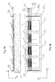
- Fig. 6 and Fig. 7 From Fig. 6 and Fig. 7 are heat sink 15, 16 with a square or with an octagonal cross section visible. On the heat sink 15 with a square cross section are on the Outside surfaces four solid-state laser units 1 is arranged. On the Heatsinks 16 with octagonal cross-section are on the outside eight solid-state laser units 1 arranged. The one from each this solid state laser units 1 emerging laser radiation 14 is parallel to the laser radiation 14 coming from the other Solid-state laser units 1 exits, so that these laser radiation be easily focused in a common focus area can.
- heat sink with others for example, three or five or many Provide geometries such that three, five or a variety of Solid-state laser units 1 arranged on the outer surfaces can be.
- Fig. 8a is another embodiment of a The laser device according to the invention can be seen in which a Heat sink 17 is used, which has a stepped top having.
- the individual stages 18a, 18b, 18c, 18d are each in the Z direction offset against each other.
- a solid-state laser unit 1 is arranged, which, as shown by the arrows 19 is indicated, pumped with corresponding pumping light can be. From each of the solid-state laser units 1 can according to the embodiment according to FIG. 2 and FIG. 3 Laser radiation 14 exit.
- FIGS. 9a and 9b show a further embodiment of a Laser device according to the invention, in which a plurality of Solid state laser units 1 in succession on a heat sink 21st are arranged.
- the heat sink 21 has no on its surface Steps up. Rather, all solid-state laser units are 1 arranged at the same height with respect to the z-direction. To this Way, this occurs in one of the solid-state laser units 1 generated Laser light through the other solid state laser units 1 therethrough.
- those for the individual solid-state laser units 1 provided pump light sources arranged such that the optical pumped channels 4 of the individual solid-state laser units 1 in the x direction essentially aligned with each other.
- FIGS. 9a and 9b an external resonator with one in Fig. 9a and Fig. 9b left shown highly reflective resonator mirror 22 and a in Fig. 9a and Fig. 9b are provided with a right-angled resonator mirror 23 be, which serves as an output coupler. From Fig. 9b is again visible, that the laser radiation 14 emerging from the laser device spaced apart in the y-direction and adjacent to each other arranged partial beams 24 consists.
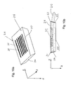
- Fig. 10a and Fig. 10b is another embodiment of a Solid state laser unit 25 according to the invention can be seen.
- These Solid-state laser unit 25 can in particular completely it can be unstructured, that is, it can be made from a laser-active medium such as Nd: YAG exist without any one whatsoever a kind of sandwich structure consisting of active and non-active areas is provided.
- a laser-active medium such as Nd: YAG exist without any one whatsoever a kind of sandwich structure consisting of active and non-active areas is provided.
- 10b are the end-side exit surfaces 26, 27 mirrored, wherein
- the left in Fig. 10b left exit surface 26 high reflective mirrored
- the right in Fig. 10b exit surface 27 is only partially reflecting mirrored, so that this as an output coupler acts.
- the resonator is thus between the exit surfaces 26, 27th formed, wherein at the upper entrance surface 28 for pump radiation the generated laser radiation 29 is also reflected.
- Fig. 10a clearly visible, not up to the front edges of the Solid state laser unit 25 or not to the Exit surfaces 26, 27 adjacent, so that no laser radiation 29th arises, which could leak in the upper edge region 31, 32.
- Fig. 10b is the hatched area, the extension of the pumped channels 30 indicated.
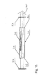
- Fig. 11 is another embodiment of a Solid state laser unit 31 according to the invention can be seen, the also exit surfaces 32, 33, which with the upper Entrance surface 34 include an angle less than 90 °. However, that is the angle in the embodiment according to FIG. 11 is chosen such that that the laser radiation emerging from the exit surfaces 32, 33 35 substantially parallel to the upper entrance surface 34 of the Solid-state laser unit 31 emerges.
- the embodiment according to FIG. 11 shows external resonator mirrors 36, 37, which are shown in FIG for example, as a highly reflective mirror and as an output coupler can be trained. Also in Fig. 11 is in turn by the hatched area the extent of the pumped channels 30th indicated.
- FIGS. 10a and 10b or as shown in FIG. 11 may also instead of Nd: YAG consist of other laser active media, as in the The foregoing has been carried out to the solid-state laser unit 1.
- Solid state laser unit 31 also in the embodiments with a plurality of solid-state laser units according to FIGS. 6, 7, 8a, 8b and according to FIGS. 9 a, 9 b instead of the solid-state laser unit 1 use.
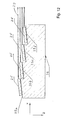
- FIG. 12 is another embodiment of a The laser device according to the invention can be seen in which on the Top of a stepped heat sink 38 solid state laser units 25 according to the embodiment according to FIGS. 10a and 10b are applied.
- the laser device according to FIG. 12 corresponds to FIG Essentially the laser device according to FIGS. 8a and 8b with the Difference that the steps 39 a, 39 b, 39 c, 39 d of the heat sink 38th an angle with the propagation direction (x) of the laser light 29th Include, so that from the individual solid-state laser units 25 emergent partial beams parallel to each other, the laser device leave and above or below the emerging from the other solid-state laser units 25 Partial beams run.
Abstract
Description
Die vorliegende Erfindung betrifft eine Laservorrichtung umfassend mindestens eine Festkörperlasereinheit mit mindestens einem aktiven Bereich, in dem Laserstrahlung erzeugt werden kann, sowie mindestens eine Halbleiterlaservorrichtung, die Pumplicht für das optische Pumpen des mindestens einen aktiven Bereichs der mindestens einen Festkörperlasereinheit erzeugen kann. Weiterhin betrifft die vorliegende Erfindung ein Verfahren zum Betrieb einer derartigen Laservorrichtung gemäß dem Oberbegriff des Anspruchs 18.The present invention relates to a laser device comprising at least one solid-state laser unit with at least one active Area in which laser radiation can be generated, as well at least one semiconductor laser device, the pumping light for the optical pumps of the at least one active region of the can generate at least one solid-state laser unit. Farther The present invention relates to a method for operating a Such a laser device according to the preamble of the claim 18th
Eine Vorrichtung und ein Verfahren der vorgenannten Art sind aus der US-Anmeldung US 2002/0181534 A1 bekannt. Es handelt sich bei der darin beschriebenen Laservorrichtung um einen Hochleistungslaser der als Festkörperlasereinheit einen sogenannten Slab eines Lasermaterials nutzt. Beispielsweise besteht dieser Slab aus drei Schichten, nämlich einem mittleren aktiven Bereich, der beispielsweise aus Nd:YAG besteht, sowie aus zwei äußeren Schichten, die die mittlere Schicht sandwichartig umgeben, wobei diese beiden äußeren Schichten beispielsweise aus undotiertem YAG bestehen können. Bei einem derartigen Slab ist der aktive Bereich eine vergleichsweise dünne Schicht, die senkrecht zur Schichtdicke eine wesentlich größere Ausdehnung aufweist. Die umgebenen Schichten aus undotiertem Material können dabei beispielsweise zur Pumplichtbündelung dienen. Weiterhin gewährleisten die umgebenden undotierten Schichten, dass in den der Pumplichtquelle zugewandten Randbereichen der aktiven Schicht keine Verluste bei Austritt aus Kantenbereichen auftreten, weil sich an die Ränder der aktiven Schicht die äußeren Schichten übergangslos anschließen.A device and a method of the aforementioned type are known from US application US 2002/0181534 A1. It concerns with the described therein laser device to a high power laser the so-called slab of a solid-state laser unit Laser material uses. For example, this slab consists of three Layers, namely a middle active area, the for example, consists of Nd: YAG, as well as two outer Layers sandwiching the middle layer, wherein these two outer layers, for example, undoped YAG can exist. In such a slab is the active area a comparatively thin layer perpendicular to the layer thickness has a much larger extension. The surrounded Layers of undoped material can be used for example for Pump light bundling serve. Furthermore, the surrounding ones ensure undoped layers that in the pumping light source facing Edge areas of the active layer no losses on exit from Edge areas occur because of the edges of the active Layer the outer layers connect seamlessly.
Aufgrund der Tatsache, dass der aktive Bereich zwar eine geringe Schichtdicke aufweist, trotzdem jedoch in einer zweiten zur Schichtdicke und zur Ausbreitungsrichtung des erzeugten Laserstrahls senkrechten Richtung eine vergleichsweise große Breite aufweist, ergibt sich bei einem derartigen Hochleistungslaser eine sehr große Divergenz. Die Divergenz des Laserstrahls ist insbesondere proportional zu dem Quotienten D/L, wobei D die Breite der Austrittsfläche und L die Länge des Resonators des Lasers ist (siehe dazu auch Fig. 4). Eine große Divergenz erweist sich bei sehr vielen Anwendungen als nachteilig, weil stark divergente Laserstrahlen nur mit großen Verlusten in eine Lichtleitfaser mit kleinem Querschnitt eingekoppelt werden können.Due to the fact that while the active area is low Layer thickness, but nevertheless in a second to Layer thickness and the propagation direction of the generated Laser beam perpendicular direction a comparatively large width has, results in such a high-power laser a very big divergence. The divergence of the laser beam is in particular proportional to the quotient D / L, where D is the width the exit surface and L is the length of the resonator of the laser (see also Fig. 4). A big divergence turns out very much many applications as disadvantageous, because strongly divergent Laser beams only with large losses in an optical fiber with Small cross-section can be coupled.
Bei der vorgenannten US-Patentanmeldung sind diverse Methoden aus dem Stand der Technik beschrieben, um auf die Strahlqualität eines aus einem Slab ausgekoppelten Laserstrahls zu verbessern. Insbesondere wird dies in der Regel durch aufwändige Strukturierung des Slabs versucht. Weiterhin erzeugen Laservorrichtungen mit einem Slab als Festkörperlasereinheit in der Regel Multimodelaserstrahlung, so dass im Stand der Technik mit ausgesprochen kompliziert aufgebauten Resonatoren versucht wurde, Einfluss auf das Modenspektrum zu nehmen.In the aforementioned US patent application are various methods described from the prior art to the beam quality to improve a decoupled from a slab laser beam. In particular, this is usually due to elaborate structuring of the slab tries. Furthermore, laser devices generate with one Slab as solid-state laser unit usually multimode laser radiation, so in the state of the art with decidedly complicated built resonators was trying to influence the Fashion spectrum to take.
Das der vorliegenden Erfindung zugrundeliegende Problem ist die Schaffung einer Laservorrichtung der eingangs genannten Art, bei der mit einfachen Mitteln eine vergleichsweise kleine Divergenz des von der Laservorrichtung erzeugten Laserstrahls erreicht werden kann. Weiterhin soll ein Verfahren zum Betrieb der eingangs genannten Art angegeben werden, mit dem ein Laserstrahl mit vergleichsweise kleiner Divergenz erzeugt werden kann.The problem underlying the present invention is the Creation of a laser device of the type mentioned, in which with simple means a comparatively small divergence of the laser device generated laser beam can be achieved. Furthermore, a method for operating the aforementioned type be given, with a laser beam with comparatively small divergence can be generated.
Dies wird erfindungsgemäß hinsichtlich der Laservorrichtung durch
eine Laservorrichtung der eingangs genannten Art mit den
kennzeichnenden Merkmalen des Anspruchs 1 sowie hinsichtlich des
Verfahrens durch ein Verfahren der eingangs genannten Art mit den
kennzeichnenden Merkmalen des Anspruchs 22 erreicht. Die
Unteransprüche betreffen bevorzugte Weiterbildungen der Erfindung. This is inventively with respect to the laser device
a laser device of the type mentioned with the
characterizing features of
Gemäß Anspruch 1 ist vorgesehen, dass die Laservorrichtung derart
ausgebildet ist, dass das Pumplicht während des Betriebs der
Laservorrichtung in dem mindestens einen aktiven Bereich eine
Mehrzahl von beabstandet zueinander angeordneten optisch
gepumpten Kanälen erzeugen kann, in denen jeweils ein Teilstrahl der
Laserstrahlung erzeugt werden kann. Durch die Aufteilung des
Pumplichtes in zueinander beabstandete Kanäle wird die Divergenz
der gesamten Laserstrahlung letztlich durch die Divergenz der
einzelnen innerhalb der einzelnen Kanäle erzeugten Teilstrahlen der
Laserstrahlung bestimmt. Aufgrund der Tatsache, dass ein jeder der
Teilstrahlen eine kleinere Breite aufweist als die gesamte
Austrittfläche der beispielsweise als Slab ausgebildeten
Festkörperlasereinheit, ist die Divergenz eines jeden der Teilstrahlen
deutlich kleiner als die Divergenz der vorgenannten aus dem Stand
der Technik bekannten aus Slabs ausgekoppelten Laserstrahlen.
Damit ist aber auch die Divergenz der gesamten aus der
erfindungsgemäßen Laservorrichtung ausgekoppelten Laserstrahlung
kleiner als die der Laserstrahlung aus der vorbekannten
Laservorrichtung.According to
Durch das Vorsehen von zueinander beabstandeten optisch gepumpten Kanälen kann die erfindungsgemäße Laservorrichtung ansonsten vergleichsweise einfach aufgebaut sein. Insbesondere müssen auch der aktive Bereich und der Resonator nicht sonderlich strukturiert werden, um Einfluss auf das Modenspektrum der Laservorrichtung zu nehmen.By providing spaced apart optically pumped channels, the laser device according to the invention otherwise be comparatively simple. Especially also the active area and the resonator do not have to be very special be structured to influence the fashion spectrum of the To take laser device.
Gemäß Anspruch 2 ist vorgesehen, dass die Laservorrichtung Mittel
zur Einbringung des von der mindestens einen
Halbleiterlaservorrichtung erzeugten Pumplichtes in den mindestens
einen aktiven Bereich der mindestens einen Festkörperlasereinheit
aufweist. According to
Diese Mittel können gemäß Anspruch 3 Linsenmittel umfassen, die
das von der mindestens einen Halbleiterlaservorrichtung erzeugte
Pumplicht zumindest in einer zur Ausbreitungsrichtung des
Pumplichtes senkrechten Richtung zumindest teilweise kollimieren
können.These agents may according to
Gemäß Anspruch 4 können dabei die Linsenmittel als Array von
Zylinderlinsen ausgebildet sein.In this case, according to
Gemäß Anspruch 5 können die Mittel zur Einbringung eine
Anpassungsoptik umfassen, die die Ausdehnung des Pumplichtes in
der zu seiner Ausbreitungsrichtung senkrechten Ebene an die
Ausdehnung des mindestens einen aktiven Bereichs der mindestens
einen Festkörperlasereinheit anpassen kann.According to
Eine bevorzugte Ausführungsform gemäß Anspruch 6 sieht vor, dass
die mindestens eine Halbleiterlaservorrichtung als Stack von
Laserdiodenbarren ausgebildet ist. Insbesondere kann dabei jedem
Laserdiodenbarren eine der vorgenannten Zylinderlinsen zur
Kollimierung des von dem Laserdiodenbarren ausgehenden Lichtes in
der Fast-Axis zugeordnet sein. Ein Stack von Laserdiodenbarren kann
eine sehr große Pumpenergie erzeugen, so dass die
erfindungsgemäße Laservorrichtung als Hochleistungslaser betrieben
werden kann.A preferred embodiment according to
Anspruch 7 sieht vor, dass der aktive Bereich transversal gepumpt
werden kann, insbesondere in einer zu der Ausbreitungsrichtung der
Laserstrahlung senkrechten Richtung. Dabei kann der aktive Bereich
insbesondere in einer Richtung senkrecht zu seiner dünnsten
Ausdehnung gepumpt werden.
Anspruch 8 sieht dazu vor, das der aktive Bereich in der Ausbreitungsrichtung des Pumplichtes kleiner, insbesondere deutlich kleiner, als in den dazu senkrechten Richtungen ist. Der aktive Bereich kann somit durchaus dem aktiven Bereich der aus dem vorgenannten Stand der Technik bekannten Laservorrichtung entsprechen. Insbesondere kann jedoch der aktive Bereich erfindungsgemäß unstrukturiert sein.Claim 8 provides that the active area in the Propagation direction of the pump light smaller, especially clear smaller than in the perpendicular directions. The active one Area can thus be quite the active area of the the aforementioned prior art known laser device correspond. In particular, however, the active area can be unstructured according to the invention.
Gemäß Anspruch 9 besteht die Möglichkeit, dass die optisch
gepumpten Kanäle parallel zueinander in dem aktiven Bereich
angeordnet sind. Aus parallel zueinander angeordneten optisch
gepumpten Kanälen treten zueinander parallele Teilstrahlen der
Laserstrahlung aus, so dass diese Teilstrahlen problemlos in einen
gemeinsamen Fokusbereich fokussierbar sind.According to
Gemäß Anspruch 10 kann vorgesehen sein, dass die Tiefe der optisch
gepumpten Kanäle in Ausbreitungsrichtung des Pumplichtes durch die
Absorptionsfähigkeit des aktiven Bereichs für Licht mit der
Wellenlänge des Pumplichtes gegeben ist. Insbesondere kann durch
einen entsprechend großen Absorptionskoeffzienten erreicht werden,
dass das Pumplicht nur ein kleines Stück weit in den aktiven Bereich
eindringt, so dass auch in der Richtung, in der der aktive Bereich
deutlich kleiner ist als in den dazu senkrechten Richtungen, die Dicke
des aktiven Bereiches nicht komplett gepumpt wird. Auf diese Weise
können optisch gepumpte Kanäle mit sehr kleinem Querschnitt
realisiert werden.According to
Es besteht insbesondere die Möglichkeit, dass die Festkörperlasereinheit neben einem aktiven Bereich einen nicht aktiven Bereich, beispielsweise einen nicht mit laseraktiven Zentren dotierten Bereich aufweist. Diese beiden Bereiche können schichtartig übereinander angeordnet sein, wie dies aus dem vorgenannten Stand der Technik bekannt ist. Beispielsweise können dabei die optisch gepumpten Kanäle nur im Grenzbereich des aktiven Bereichs zu dem nicht aktiven Bereich angeordnet sein. There is in particular the possibility that the Solid state laser unit next to an active area one not active area, for example one not with laser active centers having doped region. These two areas can be layered be arranged one above the other, as from the aforementioned state the technique is known. For example, while the optical pumped channels only in the boundary region of the active area to the not active area be arranged.
Gemäß Anspruch 11 kann vorgesehen sein, dass die Breite eines
jeden der optisch gepumpten Kanäle in einer Richtung senkrecht zur
Ausbreitungsrichtung der aus der mindestens einen
Festkörperlasereinheit austretenden Laserstrahlung durch die
Anordnung und/oder die Beschaffenheit der zur Kollimierung des
Pumplichtes verwendeten Linsenmittel gegeben ist. Insbesondere
kann bei sehr kleinem Abstand der Zylinderlinsen zu den einzelnen
Laserdiodenbarren erreicht werden, dass die die Anteile des
Pumplichtes, die jeweils für das Pumpen eines einzelnen optisch zu
pumpenden Kanals verwendet werden, eine sehr geringe Breite
aufweisen.According to
Gemäß Anspruch 12 besteht die Möglichkeit, dass die
Laservorrichtung einen externen Resonator, insbesondere einen
Resonator mit zwei Resonatorspiegeln aufweist. Erfindungsgemäß
kann der Resonator sehr einfach aufgebaut sein, weil aufgrund der
zueinander beabstandeten optisch gepumpten Kanäle eine geringe
Divergenz erreicht werden kann, ohne dass mit zusätzlichen
aufwendigen Mitteln auf das Modenspektrum der Laserstrahlung
Einfluss genommen werden muss.According to
Alternativ dazu kann gemäß Anspruch 13 die Laservorrichtung einen
internen Resonator aufweisen, der insbesondere durch zumindest
teilweise verspiegelte Austrittsflächen des mindestens einen aktiven
Bereiches der mindestens einen Festkörperlasereinheit gebildet wird.Alternatively, according to
Gemäß Anspruch 14 besteht die Möglichkeit, dass die
Laservorrichtung eine Mehrzahl von Festkörperlasereinheiten
umfasst, die insbesondere derart angeordnet sind, dass die aus den
einzelnen Festkörperlasereinheiten austretenden Laserstrahlen im
Wesentlichen parallel zueinander sind. Die aus den einzelnen
Festkörperlasereinheiten austretenden Laserstrahlen lassen sich
somit problemlos in einen gemeinsamen Fokusbereich fokussieren. According to
Durch die Verwendung mehrerer Festkörperlasereinheiten kann die Gesamtleistung der von der Laservorrichtung ausgebbaren Laserstrahlung gesteigert werden.By using multiple solid state laser units, the Total output of the output from the laser device Laser radiation can be increased.
Gemäß Anspruch 15 ist vorgesehen, dass die mindestens eine
Festkörperlasereinheit mit einem Kühlkörper wärmeleitend verbunden
ist.According to
Gemäß Anspruch 16 ist vorgesehen, dass auf der Außenseite des
Kühlkörpers eine Mehrzahl von Festkörperlasereinheiten angebracht
ist, wobei aus diesen Festkörperlasereinheiten austretende
Laserstrahlen im Wesentlichen parallel zueinander sind. Es besteht
somit die Möglichkeit, einen Kühlkörper für mehrere
Festkörperlasereinheiten zu verwenden.According to
Dabei kann Anspruch 17 vorsehen, dass der Kühlkörper einen
rechteckigen, einen dreieckigen, einen quadratischen, einen
fünfeckigen, einen sechseckigen, einen siebeneckigen, einen
achteckigen oder einen anderen vieleckigen Querschnitt aufweist.
Beispielsweise bei einem quadratischen Querschnitt können auf den
Außenseiten des Kühlkörpers vier Festkörperlasereinheiten
angeordnet sein. Gemäß einem anderen Beispiel können auf einem
Kühlkörper mit achteckigem Querschnitt acht Festkörperlasereinheiten
angeordnet werden. Durch diese vergleichsweise große Zahl von
Festkörperlasereinheiten kann mittels der erfindungsgemäßen
Laservorrichtung eine sehr große Ausgangsleistung erzielt werden.In this case,
Gemäß Anspruch 18 kann vorgesehen sein, dass die Festkörperlasereinheiten auf der Außenseite des Kühlkörpers in Ausbreitungsrichtung der Laserstrahlung hintereinander angeordnet sind, wobei insbesondere die optisch gepumpten Kanäle in Ausbreitungsrichtung der Laserstrahlung im Wesentlichen miteinander fluchten. Beispielsweise kann bei einer derartigen Anordnung ein Resonator mit zwei externen Resonatorspiegeln vorgesehen sein, so dass das von einzelnen Festkörperlasereinheiten ausgehende Laserlicht durch sämtliche andere Festkörperlasereinheiten hindurchtritt.According to claim 18 it can be provided that the Solid state laser units on the outside of the heat sink in Spreading direction of the laser radiation arranged one behind the other in particular the optically pumped channels in Propagation direction of the laser radiation substantially with each other aligned. For example, in such an arrangement a Resonator be provided with two external resonator mirrors, so that emanating from individual solid state laser units Laser light through all other solid-state laser units passes.
Gemäß Anspruch 19 kann vorgesehen sein, dass der Kühlkörper
mindestens eine abgestufte Oberfläche aufweist, wobei auf
mindestens zwei Stufen der gestuften Oberfläche jeweils mindestens
eine Festkörperlasereinheit angeordnet ist. Insbesondere kann der
Kühlkörper dabei derart gestaltet sein, dass das von den einzelnen
Festkörperlasereinheiten ausgehende Laserlicht parallel zueinander
aus der Laservorrichtung austritt, wobei die einzelnen Teilstrahlen der
von den einzelnen Festkörperlasereinheiten ausgehenden
Laserstrahlung übereinander beziehungsweise nebeneinander
angeordnet sind. Das Licht einer einzelnen Festkörperlasereinheit tritt
somit nicht durch eine andere Festkörperlasereinheit hindurch
sondern über diese hinweg.According to
Gemäß Anspruch 20 kann vorgesehen sein, dass die
Festkörperlasereinheit derart ausgebildet ist, dass die in ihr erzeugte
Laserstrahlung im Bereich ihrer der Pumplichtquelle zugewandten
Oberfläche eine Totalreflexion erfährt.According to
Gemäß Anspruch 21 kann dabei vorgesehen sein, dass die Austrittsflächen der mindestens einen Festkörperlasereinheit mit ihrer der Pumplichtquelle zugewandten Eintrittsfläche einen Winkel kleiner als 90° einschließen. Wenn beispielsweise die Austrittsflächen zumindest teilweise verspiegelt sind, wird auf diese Weise innerhalb der Festkörperlasereinheit Laserstrahlung erzeugt, die nicht im Kantenbereich zwischen Austrittsfläche der Laserstrahlung und Eintrittsfläche des Pumplichtes austritt sondern ein Stück weit von diesem Kantenbereich beabstandet. Dadurch werden Verluste im Bereich der Kante vermieden. Alternativ dazu könnte auch mit einem externen Resonator eine Verteilung der Laserstrahlung innerhalb der Festkörperlasereinheit erzielt werden, die das Austreten von Laserstrahlung in dem vorgenannten Kantenbereich verhindert.According to claim 21 it can be provided that the Exit surfaces of the at least one solid state laser unit with their the pumping light source facing entrance surface an angle smaller than 90 °. For example, if the exit surfaces are at least partially mirrored, this way within the solid state laser unit generates laser radiation that is not in the Edge region between the exit surface of the laser radiation and Entrance surface of the pump light exits but a little way from this edge area spaced. This will cause losses in the Area of the edge avoided. Alternatively, could also with a external cavity a distribution of laser radiation within the Solid state laser unit can be achieved, which is the leakage of Prevents laser radiation in the aforementioned edge region.
Das Verfahren gemäß Anspruch 22 sieht vor, dass das Pumplicht in
dem mindestens einen aktiven Bereich eine Mehrzahl von
beabstandet zueinander angeordneten optisch gepumpten Kanälen
erzeugt, in denen jeweils ein Teilstrahl der Laserstrahlung erzeugt
wird. Der aktive Bereich kann somit vollständig unstrukturiert sein,
weil durch die entsprechende Gestaltung des Pumplichtes in dem
aktiven Bereich nebeneinander gepumpte und nicht gepumpte
Abschnitte erzeugt werden, wobei sich die gepumpten Abschnitte
kanalartig, insbesondere über die gesamte Länge des aktiven
Bereichs erstrecken.The method according to
Alternativ besteht die Möglichkeit, dass die Kanäle sich nicht kontinuierlich erstrecken, sondern in ihrer Längsrichtung gepumpte und nicht gepumpte Abschnitte aufweisen. Alternatively, there is a possibility that the channels are not extend continuously but pumped in their longitudinal direction and not pumped sections.
Weitere Merkmale und Vorteile der vorliegenden Erfindung werden deutlich anhand der nachfolgenden Beschreibung bevorzugter Ausführungsbeispiele unter Bezugnahme auf die beiliegenden Abbildungen. Darin zeigen
- Fig. 1
- eine schematische perspektivische Darstellung einer Festkörperlasereinheit einer erfindungsgemäßen Laservorrichtung;
- Fig. 2
- eine schematische Seitenansicht einer erfindungsgemäßen Laservorrichtung;
- Fig. 3
- eine schematische Ansicht gemäß dem Pfeil III in Fig. 2;
- Fig. 4
- eine schematische Draufsicht auf einen Resonator einer Festkörperlasereinheit gemäß dem Stand der Technik;
- Fig. 5
- eine Fig. 4 entsprechende Ansicht auf einen Resonator einer Festkörperlasereinheit einer erfindungsgemäßen Laservorrichtung;
- Fig. 6
- eine schematische Draufsicht auf eine weitere Ausführungsform einer erfindungsgemäßen Laservorrichtung;
- Fig. 7
- eine schematische Draufsicht auf eine weitere Ausführungsform einer erfindungsgemäßen Laservorrichtung;
- Fig. 8a
- eine schematische Seitenansicht einer weiteren Ausführungsform einer erfindungsgemäßen Laservorrichtung;
- Fig. 8b
- eine Ansicht gemäß dem Pfeil VIIIb in Fig. 8a;
- Fig. 9a
- eine schematische Seitenansicht einer weiteren Ausführungsform einer erfindungsgemäßen Laservorrichtung;
- Fig. 9b
- eine Draufsicht auf die Laservorrichtung gemäß Fig. 9a;
- Fig. 10a
- eine perspektivische Ansicht einer weiteren Ausführungsform einer Festkörperlasereinheit einer erfindungsgemäßen Laservorrichtung;
- Fig. 10b
- eine schematische Seitenansicht der Festkörperlasereinheit gemäß Fig. 10a während des Betriebs;
- Fig. 11
- eine schematische Seitenansicht eines Resonators mit einer weiteren Ausführungsform einer Festkörperlasereinheit einer erfindungsgemäßen Laservorrichtung;
- Fig. 12
- eine schematische Seitenansicht einer weiteren Ausführungsform einer erfindungsgemäßen Laservorrichtung.
- Fig. 1
- a schematic perspective view of a solid state laser unit of a laser device according to the invention;
- Fig. 2
- a schematic side view of a laser device according to the invention;
- Fig. 3
- a schematic view according to the arrow III in Fig. 2;
- Fig. 4
- a schematic plan view of a resonator of a solid state laser unit according to the prior art;
- Fig. 5
- a view corresponding to FIG. 4 on a resonator of a solid-state laser unit of a laser device according to the invention;
- Fig. 6
- a schematic plan view of a further embodiment of a laser device according to the invention;
- Fig. 7
- a schematic plan view of a further embodiment of a laser device according to the invention;
- Fig. 8a
- a schematic side view of another embodiment of a laser device according to the invention;
- Fig. 8b
- a view according to the arrow VIIIb in Fig. 8a;
- Fig. 9a
- a schematic side view of another embodiment of a laser device according to the invention;
- Fig. 9b
- a plan view of the laser device of FIG. 9a;
- Fig. 10a
- a perspective view of another embodiment of a solid state laser unit of a laser device according to the invention;
- Fig. 10b
- a schematic side view of the solid state laser unit of Figure 10a during operation.
- Fig. 11
- a schematic side view of a resonator with a further embodiment of a solid state laser unit of a laser device according to the invention;
- Fig. 12
- a schematic side view of another embodiment of a laser device according to the invention.
In einigen der Zeichnungen sind kartesische Koordinatensysteme zur besseren Orientierung eingezeichnet.In some of the drawings are Cartesian coordinate systems for better orientation.
Aus Fig. 1 ist schematisch eine Festkörperlasereinheit 1 einer
erfindungsgemäßen Laservorrichtung ersichtlich. Die
Festkörperlasereinheit 1 ist als sogenannter Slab ausgeführt und
umfasst einen aktiven Bereich 2 sowie einen nicht aktiven Bereich 3. From Fig. 1 is a solid state laser unit 1 a schematically
The laser device of the invention can be seen. The
Solid-
Der aktive Bereich 2 kann beispielsweise mit laseraktiven Zentren
dotiert sein, wohingegen der nicht aktive Bereich 3 undotiert ist. Der
aktive Bereich 2 der Festkörperlasereinheit 1 weist in z-Richtung eine
vergleichsweise geringe Ausdehnung auf, wohingegen er in der dazu
senkrechten y-Richtung deutlich ausgedehnter als in z-Richtung ist. In
x-Richtung ist der aktive Bereich 2 ausgedehnter als in y-Richtung.
Laserstrahlung, die in dem aktiven Bereich 2 erzeugt wird, breitet sich
in positiver und in negativer x-Richtung in diesem aus.The
Bei dem nicht aktiven Bereich 3 kann es sich beispielsweise um nicht
dotiertes YAG handeln, wohingegen der aktive Bereich 2 aus Nd:YAG
bestehen kann. Der aktive Bereich 2 und der nicht aktive Bereich 3
können durch an sich aus dem Stand der Technik bekannte
klebstofffreie Verbindungstechniken miteinander fest verbunden sein.
Derartige Slab-Strukturen werden im Stand der Technik (siehe dazu
beispielsweise US 2002 181 534 A1 ) aus Gründen der
Pumplichtbündelungen und der Wellenleitung des erzeugten
Laserstrahls verwendet.For example, the
Anstelle von Nd:YAG können andere laseraktive Medien wie beispielsweise Nd:YVO4, Nd:GdVO4, Yb:YAG, Yb:KY(WO4)2 oder dergleichen verwendet werden.Instead of Nd: YAG, other active laser media such as Nd: YVO 4, Nd: GdVO 4, Yb: YAG, Yb: KY (WO 4) 2 or the like may be used.
Aus Fig. 1 sind weiterhin in dem aktiven Bereich in y-Richtung
beabstandet zueinander angeordnete parallele optisch gepumpte
Kanäle 4 eingezeichnet. In diesen gepumpten Kanälen 4 werden
voneinander separierte Teilstrahlen der zu erzeugenden
Laserstrahlung generiert. Aus Fig. 4 ist eine Festkörperlasereinheit 1
ersichtlich, die im Prinzip ähnlich aufgebaut sein kann wie die
Festkörperlasereinheit 1 gemäß Fig. 1. Wenn eine derartige
Festkörperlasereinheit 1 über die gesamte Breite D ihres aktiven
Bereichs gepumpt wird, entsteht Laserstrahlung, die in y-Richtung
eine Ausdehnung aufweist, die im Prinzip der Breite D der
Austrittsflächen 5 entspricht. In Fig. 4 sind weiterhin
Resonatorspiegel 6 eingezeichnet, von denen beispielsweise einer als
Auskoppler und der andere als hochreflektierender Spiegel
ausgebildet sein können. Die Entfernung zwischen den beiden
Resonatorspiegeln 6 entspricht der Resonatorlänge L. Die Divergenz,
die die aus dem Resonator austretende Laserstrahlung aufweist, ist
dem Quotient D/L proportional. Aus diesem Grund wird bei einer
vergleichsweise großen Breite D die austretende Laserstrahlung eine
sehr große Divergenz aufweisen.From Fig. 1 are further in the active region in the y direction
spaced apart parallel optically pumped
Aus Fig. 5 ist eine Festkörperlasereinheit 1 einer erfindungsgemäßen
Laservorrichtung ersichtlich, die derart optisch gepumpt ist, dass sich
in x-Richtung erstreckende, in y-Richtung zueinander beabstandete
gepumpte Kanäle 4 entstehen, in denen Teilstrahlen der
Laserstrahlung erzeugt werden. In Fig. 5 sind weiterhin
Resonatorspiegel 6 eingezeichnet, die einen Resonator mit einer
Resonatorlänge L bilden. Die aus den einzelnen optisch gepumpten
Kanälen 4 austretenden Teilstrahlen weisen im Bereich der
Austrittsfläche 5 eine Breite d in y-Richtung auf, die wesentlich
kleiner ist als die Breite D der Austrittsfläche gemäß Fig. 4. Die
Divergenz der aus der erfindungsgemäßen Laservorrichtung
austretenden Laserstrahlung ist aufgrund der voneinander in y-Richtung
beabstandeten Kanäle 4 proportional zu dem Quotienten d/L
und damit wesentlich kleiner als die Divergenz der Laserstrahlung
einer Laservorrichtung gemäß dem Stand der Technik, wie dies
schematisch in Fig. 4 angedeutet ist.From Fig. 5 is a solid
Aus Fig. 2 und Fig. 3 ist eine erste Ausführungsform einer
erfindungsgemäßen Laservorrichtung ersichtlich. Bei dieser
Ausführungsform wird eine Festkörperlasereinheit 1 verwendet, die
der Festkörperlasereinheit 1 gemäß Fig. 1 entspricht. Die
Festkörperlasereinheit 1 ist mit der Unterseite ihres aktiven Bereichs
2 auf einem Kühlkörper 7 angebracht.From Fig. 2 and Fig. 3 is a first embodiment of a
The laser device of the invention can be seen. At this
Embodiment, a solid-
Als Pumplichtquelle dient eine Halbleiterlaservorrichtung 8, die als
Stack von Laserdiodenbarren ausgebildet ist. Die einzelnen
Laserdiodenbarren sind dabei in y-Richtung nebeneinander
angeordnet und erstrecken sich in x-Richtung. Aus Fig. 2 ist
ersichtlich, dass die einzelnen Laserdiodenbarren in y-Richtung derart
voneinander beabstandet angeordnet sind, dass von den
Laserdiodenbarren voneinander beabstandete Teilstrahlen 9 des
Pumplichtes ausgehen.As the pumping light source is a semiconductor laser device 8, which as
Stack of laser diode bars is formed. The single ones
Laser diode bars are next to each other in the y-direction
arranged and extend in the x direction. From Fig. 2 is
It can be seen that the individual laser diode bars in the y direction in such a way
spaced from each other, that of the
Laser diode bars spaced-apart
Die y-Richtung in Fig. 2 entspricht der sogenannten Fast-Axis, das
heißt der Richtung, in der die Divergenz der Teilstrahlen 9 der
einzelnen Laserdiodenarrays sehr groß ist. In der dazu senkrechten x-Richtung,
der sogenannten Slow-Axis, ist die Divergenz der
Teilstrahlen vergleichsweise klein. Die einzelnen Laserdiodenbarren
können derart aufgebaut sein, dass sich in x-Richtung erstreckende
voneinander beabstandete linienförmige Emitter ausgebildet sind.
Dies ist in der schematischen Ansicht gemäß Fig. 3 nicht abgebildet,
weil aufgrund der zwar kleinen aber doch merklichen Divergenz in x-Richtung
und somit in Slow-Axis-Richtung bei Fortschreiten der
einzelnen Teilstrahlen in z-Richtung eine Überlagerung stattfindet, so
dass bei Erreichen des aktiven Bereichs 2 der Festkörperlasereinheit
1 ein in x-Richtung im Wesentlichen gleichmäßig gepumpter Kanal 4
entsteht.The y-direction in Fig. 2 corresponds to the so-called fast-axis, the
is the direction in which the divergence of the
In Ausbreitungsrichtung des von der Halbleiterlaservorrichtung 8
ausgehenden Pumplichtes und somit in positiver z-Richtung schließt
sich an die Halbleiterlaservorrichtung 8 ein Array von Zylinderlinsen
10 an, deren Zylinderachsen sich in x-Richtung erstrecken. Dieses
Array von Zylinderlinsen 10 ist derart ausgebildet, dass die einzelnen
Teilstrahlen 9 hinsichtlich ihrer Fast-Axis, das heißt in y-Richtung im
Wesentlichen kollimiert werden. Auf diese Weise wirken die
Zylinderlinsen 10 als Fast-Axis-Kollimationslinsen.In the propagation direction of the semiconductor laser device 8
outgoing pump light and thus closes in positive z-direction
is an array of cylindrical lenses to the semiconductor laser device 8
10, whose cylinder axes extend in the x direction. This
Array of
In positiver z-Richtung hinter dem Array von Zylinderlinsen 10 ist eine
Anpassungsoptik 11 vorgesehen, die zur Anpassung der Größe der
Halbleiterlaservorrichtung 8 an die Festkörperlasereinheit 1 dient. Die
Anpassungsoptik 11 umfasst im abgebildeten Ausführungsbeispiel
eine bikonvexe Zylinderlinse 12 und eine sich in positiver z-Richtung
daran anschließende plankonkave Zylinderlinse 13, deren
Zylinderachsen sich in x-Richtung erstrecken. Wie insbesondere aus
Fig. 2 deutlich ersichtlich ist, werden durch die Anpassungsoptik 11
die Teilstrahlen 9 in y-Richtung leicht verdichtet und näher
aneinandergerückt.In the positive z-direction behind the array of
Die einzelnen Teilstrahlen 9 des Pumplichtes breiten sich in z-Richtung
aus und sind dabei in x-Richtung im Wesentlichen über die
gesamte Länge der Festkörperlasereinheit ausgedehnt, so dass sie
wie parallel zueinander ausgerichtete dünne Schichten von Licht in
den aktiven Bereich 2 eindringen.The individual
Die Eindringtiefe der Teilstrahlen 9 in den aktiven Bereich 2 kann
durch den Absorptionskoeffizienten des aktiven Bereiches 2 für Licht
mit der Wellenlänge der Teilstrahlen 9 vergleichsweise gut bestimmt
werden. Die Ausdehnung der Teilstrahlen 9 in y-Richtung ergibt sich
durch die Anordnung des Arrays von Zylinderlinsen 10.The penetration depth of the
In Fig. 3 ist angedeutet, dass aus den Austrittsflächen 5 des aktiven
Bereichs 2 der Festkörperlasereinheit 1 Laserstrahlung 14 nach links
und nach rechts, das heißt in positiver und negativer x-Richtung
austritt. Es besteht erfindungsgemäß die Möglichkeit, einen externen
Resonator für die Festkörperlasereinheit 1 vorzusehen,
beispielsweise in Form von Resonatorspiegeln, wie sie in Fig. 4 und
Fig. 5 abgebildet sind. Weiterhin besteht auch die Möglichkeit, die
Austrittsflächen 5 teilweise beziehungsweise einseitig total zu
verspiegeln, so dass ein interner Resonator gebildet wird.In Fig. 3 it is indicated that from the exit surfaces 5 of the
Es besteht die Möglichkeit, auf der in Fig. 3 unteren Seite des
Kühlkörpers 7 eine weitere Festkörperlasereinheit anzuordnen, die
ebenfalls von einer weiteren Halbleiterlaservorrichtung 8 gepumpt
wird. Auf diese Weise können zwei zueinander parallele Laserstrahlen
aus den beiden zueinander parallelen Festkörperlasereinheiten 1
austreten.There is a possibility on the in Fig. 3 lower side of the
Aus Fig. 6 und Fig. 7 sind Kühlkörper 15, 16 mit einem quadratischen
beziehungsweise mit einem achteckigen Querschnitt ersichtlich. Auf
dem Kühlkörper 15 mit quadratischem Querschnitt sind auf den
Außenflächen vier Festkörperlasereinheiten 1 angeordnet. Auf dem
Kühlkörper 16 mit achteckigem Querschnitt sind auf den Außenseiten
acht Festkörperlasereinheiten 1 angeordnet. Die aus einem jeden
dieser Festkörperlasereinheiten 1 austretende Laserstrahlung 14 ist
parallel zu der Laserstrahlung 14, die aus den anderen
Festkörperlasereinheiten 1 austritt, so dass diese Laserstrahlungen
problemlos in einen gemeinsamen Fokusbereich fokussiert werden
können.From Fig. 6 and Fig. 7 are
Es besteht erfindungsgemäß die Möglichkeit, Kühlkörper mit anderen
beispielsweise dreizähligen oder fünfzähligen oder vielzähligen
Geometrien vorzusehen, so dass drei, fünf oder eine Vielzahl von
Festkörperlasereinheiten 1 auf deren Außenflächen angeordnet
werden können.There is the possibility according to the invention, heat sink with others
for example, three or five or many
Provide geometries such that three, five or a variety of
Solid-
Aus Fig. 8a ist eine weitere Ausführungsform einer
erfindungsgemäßen Laservorrichtung ersichtlich, bei der ein
Kühlkörper 17 verwendet wird, der eine stufenförmige Oberseite
aufweist. Die einzelnen Stufen 18a, 18b, 18c, 18d sind jeweils in Z-Richtung
gegeneinander versetzt. Auf jeder der Stufen 18a, 18b, 18c,
18d ist eine Festkörperlasereinheit 1 angeordnet, die, wie dies durch
die Pfeile 19 angedeutet ist, mit entsprechendem Pumplicht gepumpt
werden kann. Aus jeder der Festkörperlasereinheiten 1 kann
entsprechend der Ausführungsform gemäß Fig. 2 und Fig. 3
Laserstrahlung 14 austreten.From Fig. 8a is another embodiment of a
The laser device according to the invention can be seen in which a
Aus Fig. 8b ist ersichtlich, dass die aus der Laservorrichtung
austretende Laserstrahlung 14 aus einer Reihe von Teilstrahlen 20
besteht, die über und nebeneinander matrixähnlich in Reihen und
Spalten angeordnet sind.From Fig. 8b it can be seen that the from the laser device
emerging
Fig. 9a und Fig. 9b zeigen eine weitere Ausführungsform einer
erfindungsgemäßen Laservorrichtung, bei der eine Mehrzahl von
Festkörperlasereinheiten 1 hintereinander auf einem Kühlkörper 21
angeordnet sind. Der Kühlkörper 21 weist auf seiner Oberfläche keine
Stufen auf. Vielmehr sind sämtliche Festkörperlasereinheiten 1
hinsichtlich der z-Richtung in gleicher Höhe angeordnet. Auf diese
Weise tritt das in einer der Festkörperlasereinheiten 1 erzeugte
Laserlicht durch die anderen Festkörperlasereinheiten 1 hindurch.
Insbesondere sind die für die einzelnen Festkörperlasereinheiten 1
vorgesehenen Pumplichtquellen derart angeordnet, dass die optisch
gepumpten Kanäle 4 der einzelnen Festkörperlasereinheiten 1 in x-Richtung
im Wesentlichen miteinander fluchten.FIGS. 9a and 9b show a further embodiment of a
Laser device according to the invention, in which a plurality of
Solid
Bei der aus Fig. 9a und Fig. 9b ersichtlichen Laservorrichtung kann
ein externer Resonator mit einem in Fig. 9a und Fig. 9b links
abgebildeten hochreflektierenden Resonatorspiegel 22 und einem in
Fig. 9a und Fig. 9b rechs abgebildeten Resonatorspiegel 23 versehen
sein, der als Auskoppler dient. Aus Fig. 9b ist wiederum ersichtlich,
dass die aus der Laservorrichtung austretende Laserstrahlung 14 aus
einzelnen in y-Richtung beabstandet und benachbart zueinander
angeordneten Teilstrahlen 24 besteht.In the case of the laser device apparent from FIGS. 9a and 9b
an external resonator with one in Fig. 9a and Fig. 9b left
shown highly
Aus Fig. 10a und Fig. 10b ist eine weitere Ausführungsform einer
erfindungsgemäßen Festkörperlasereinheit 25 ersichtlich. Diese
Festkörperlasereinheit 25 kann insbesondere vollkommen
unstrukturiert sein, das heißt sie kann aus einem laseraktiven Medium
wie beispielsweise Nd:YAG bestehen, ohne dass eine wie auch immer
geartete Sandwichstruktur aus aktiven und nicht aktiven Bereichen
vorgesehen ist. Um zu verhindern, dass die in der obersten Schicht
erzeugte Laserstrahlung im Bereich einer Kante aus der
Festkörperlasereinheit 25 austritt, schließen die Stirnflächen
beziehungsweise Austrittsflächen 26, 27 mit der in Fig. 10b oberen
Eintrittsfläche 28 für Pumpstrahlung einen Winkel ein, der kleiner ist
als 90°. Bei der Ausführungsform gemäß Fig. 10a und Fig. 10b sind
die stirnseitigen Austrittsflächen 26, 27 verspiegelt, wobei
beispielsweise die in Fig. 10b linke Austrittsfläche 26 hoch
reflektierend verspiegelt ist und die in Fig. 10b rechte Austrittsfläche
27 nur teilreflektierend verspiegelt ist, so dass diese als Auskoppler
wirkt. Der Resonator wird somit zwischen den Austrittsflächen 26, 27
gebildet, wobei an der oberen Eintrittsfläche 28 für Pumpstrahlung die
erzeugte Laserstrahlung 29 ebenfalls reflektiert wird.From Fig. 10a and Fig. 10b is another embodiment of a
Solid
Weiterhin ist nicht die gesamte Länge der Festkörperlasereinheit 25
gepumpt sondern nur ein sich beispielsweise über 2/3 der Länge der
Festkörperlasereinheit 25 erstreckender Bereich der gepumpten
Kanäle 30. Die Kanäle 30 erstrecken sich somit, wie dies aus Fig. 10a
deutlich ersichtlich ist, nicht bis zu den stirnseitigen Rändern der
Festkörperlasereinheit 25 beziehungsweise nicht bis an die
Austrittsflächen 26, 27 angrenzend, so dass keine Laserstrahlung 29
entsteht, die in dem oberen Kantenbereich 31, 32 austreten könnte. In
Fig. 10b ist durch die schraffierte Fläche die Ausdehnung der
gepumpten Kanäle 30 angedeutet.Furthermore, not the entire length of the solid-
Aus Fig. 11 ist eine weitere Ausführungsform einer
erfindungsgemäßen Festkörperlasereinheit 31 ersichtlich, die
ebenfalls Austrittsflächen 32, 33 aufweist, die mit der oberen
Eintrittsfläche 34 einen Winkel kleiner 90° einschließen. Allerdings ist
der Winkel bei der Ausführungsform gemäß Fig. 11 derart gewählt,
dass die aus den Austrittsflächen 32, 33 austretende Laserstrahlung
35 im Wesentlichen parallel zur oberen Eintrittsfläche 34 aus der
Festkörperlasereinheit 31 austritt. Bei der Ausführungsform gemäß
Fig. 11 sind externe Resonatorspiegel 36, 37 eingezeichnet, die
beispielsweise als hochreflektierende Spiegel und als Auskoppler
ausgebildet sein können. Auch in Fig. 11 ist wiederum durch die
schraffierte Fläche die Ausdehnung der gepumpten Kanäle 30
angedeutet.From Fig. 11 is another embodiment of a
Solid
Die Ausführungsformen gemäß Fig. 10a und Fig. 10b
beziehungsweise gemäß Fig. 11 können ebenfalls anstelle von
Nd:YAG aus anderen laseraktiven Medien bestehen, wie dies im
Voranstehenden zu der Festkörperlasereinheit 1 ausgeführt wurde.The embodiments according to FIGS. 10a and 10b
or as shown in FIG. 11 may also instead of
Nd: YAG consist of other laser active media, as in the
The foregoing has been carried out to the solid-
Es besteht weiterhin die Möglichkeit, insbesondere die
Festkörperlasereinheit 31 auch bei den Ausführungsformen mit
mehreren Festkörperlasereinheiten gemäß Fig. 6, Fig. 7, Fig. 8a, 8b
und gemäß Fig. 9a, 9b anstelle der Festkörperlasereinheit 1
einzusetzen.There is still the possibility, in particular the
Solid
Aus Fig. 12 ist eine weitere Ausführungsform einer
erfindungsgemäßen Laservorrichtung ersichtlich, bei der auf der
Oberseite eines gestuften Kühlkörpers 38 Festkörperlasereinheiten 25
entsprechend der Ausführungsform gemäß Fig. 10a und 10b
aufgebracht sind. Die Laservorrichtung gemäß Fig. 12 entspricht im
Wesentlichen der Laservorrichtung gemäß Fig. 8a und 8b mit dem
Unterschied, dass die Stufen 39a, 39b, 39c, 39d des Kühlkörpers 38
einen Winkel mit der Ausbreitungsrichtung (x) des Laserlichtes 29
einschließen, so dass die aus den einzelnen Festkörperlasereinheiten
25 austretenden Teilstrahlen parallel zueinander die Laservorrichtung
verlassen und dabei jeweils oberhalb beziehungsweise unterhalb der
aus den anderen Festkörperlasereinheiten 25 austretenden
Teilstrahlen verlaufen.From Fig. 12 is another embodiment of a
The laser device according to the invention can be seen in which on the
Top of a stepped
Claims (22)
Priority Applications (2)
| Application Number | Priority Date | Filing Date | Title |
|---|---|---|---|
| EP03020178A EP1513232A1 (en) | 2003-09-05 | 2003-09-05 | Laser device and method for operating the laser device |
| PCT/EP2004/009686 WO2005025018A1 (en) | 2003-09-05 | 2004-08-31 | Laser device and method for operating a laser device |
Applications Claiming Priority (1)
| Application Number | Priority Date | Filing Date | Title |
|---|---|---|---|
| EP03020178A EP1513232A1 (en) | 2003-09-05 | 2003-09-05 | Laser device and method for operating the laser device |
Publications (1)
| Publication Number | Publication Date |
|---|---|
| EP1513232A1 true EP1513232A1 (en) | 2005-03-09 |
Family
ID=34130152
Family Applications (1)
| Application Number | Title | Priority Date | Filing Date |
|---|---|---|---|
| EP03020178A Withdrawn EP1513232A1 (en) | 2003-09-05 | 2003-09-05 | Laser device and method for operating the laser device |
Country Status (2)
| Country | Link |
|---|---|
| EP (1) | EP1513232A1 (en) |
| WO (1) | WO2005025018A1 (en) |
Citations (5)
| Publication number | Priority date | Publication date | Assignee | Title |
|---|---|---|---|---|
| US5365538A (en) * | 1992-10-29 | 1994-11-15 | The Charles Stark Draper Laboratory Inc. | Slab waveguide pumped channel waveguide laser |
| US5521931A (en) * | 1993-11-22 | 1996-05-28 | Xerox Corporation | Nonmonolithic arrays of accurately positioned diode lasers |
| DE19811211A1 (en) * | 1998-03-10 | 1999-09-16 | Max Born Inst Fuer Nichtlinear | Multipath waveguide solid state laser or amplifier structure |
| US5987043A (en) * | 1997-11-12 | 1999-11-16 | Opto Power Corp. | Laser diode arrays with offset components |
| US20020181534A1 (en) * | 2000-10-25 | 2002-12-05 | Spectra-Physics Lasers, Inc. | Diode-pumped slab solid-state laser |
Family Cites Families (3)
| Publication number | Priority date | Publication date | Assignee | Title |
|---|---|---|---|---|
| DE4229498A1 (en) * | 1992-09-04 | 1994-03-10 | Deutsche Aerospace | Laser diode-excited solid-state laser - uses coupling mirror to provide partial feedback of each individual resonator mode |
| DE4239653C2 (en) * | 1992-11-26 | 1996-11-07 | Daimler Benz Aerospace Ag | Cooling arrangement for a solid-state laser array |
| US5485482A (en) * | 1993-12-08 | 1996-01-16 | Selker; Mark D. | Method for design and construction of efficient, fundamental transverse mode selected, diode pumped, solid state lasers |
-
2003
- 2003-09-05 EP EP03020178A patent/EP1513232A1/en not_active Withdrawn
-
2004
- 2004-08-31 WO PCT/EP2004/009686 patent/WO2005025018A1/en active Application Filing
Patent Citations (5)
| Publication number | Priority date | Publication date | Assignee | Title |
|---|---|---|---|---|
| US5365538A (en) * | 1992-10-29 | 1994-11-15 | The Charles Stark Draper Laboratory Inc. | Slab waveguide pumped channel waveguide laser |
| US5521931A (en) * | 1993-11-22 | 1996-05-28 | Xerox Corporation | Nonmonolithic arrays of accurately positioned diode lasers |
| US5987043A (en) * | 1997-11-12 | 1999-11-16 | Opto Power Corp. | Laser diode arrays with offset components |
| DE19811211A1 (en) * | 1998-03-10 | 1999-09-16 | Max Born Inst Fuer Nichtlinear | Multipath waveguide solid state laser or amplifier structure |
| US20020181534A1 (en) * | 2000-10-25 | 2002-12-05 | Spectra-Physics Lasers, Inc. | Diode-pumped slab solid-state laser |
Also Published As
| Publication number | Publication date |
|---|---|
| WO2005025018A1 (en) | 2005-03-17 |
Similar Documents
| Publication | Publication Date | Title |
|---|---|---|
| DE69631895T2 (en) | DEVICE AND METHOD FOR SIDE PUMPING AN OPTICAL FIBER | |
| EP1896893B1 (en) | Apparatus for beam shaping | |
| DE60302451T2 (en) | PUMP PROCESS FOR LASER RESONATOR AND LASER SYSTEM | |
| DE102004045912B4 (en) | Method and device for superimposing beams | |
| EP1145390B1 (en) | Laser amplification system | |
| DE102013102880B4 (en) | laser assembly | |
| EP1502336B1 (en) | Optically pumped semiconductor laser device | |
| DE19813127A1 (en) | Laser device with several laser light emitting diodes | |
| DE102006039074A1 (en) | Optical arrangement for pumping solid-state lasers | |
| DE102004053137A1 (en) | Multispectral laser with multiple gain elements | |
| EP2917985B1 (en) | Optically end-pumped slab amplifier comprising pump modules arranged in a distributed manner | |
| DE4101403C2 (en) | Semiconductor laser-pumped solid-state laser | |
| DE112019003882T5 (en) | LASER SYSTEM WITH STAIR-SHAPED SLOW-AXIS COLLIMATORS | |
| DE10204246B4 (en) | Solid-state laser amplifier system | |
| DE602006000447T2 (en) | System for optically pumping a laser source and laser source using this optical pumping system | |
| DE10296788B4 (en) | Laser pump method | |
| EP1629576B1 (en) | Method and device for pumping a laser | |
| EP1513232A1 (en) | Laser device and method for operating the laser device | |
| DE102013102891B4 (en) | laser assembly | |
| DE102004045914B4 (en) | Method and device for superimposing beams | |
| EP0903823A2 (en) | Laser element incorporating a laser array and method of fabrication | |
| DE602004003743T2 (en) | Fiber laser and method for its operation | |
| DE102020109422B4 (en) | Laser radiation transformation device and laser device | |
| EP3577514A1 (en) | Device for collimating a light beam, high-power laser, and focusing optical unit and method for collimating a light beam | |
| DE102019123533B4 (en) | Laser system and method for operating a laser system |
Legal Events
| Date | Code | Title | Description |
|---|---|---|---|
| PUAI | Public reference made under article 153(3) epc to a published international application that has entered the european phase |
Free format text: ORIGINAL CODE: 0009012 |
|
| 17P | Request for examination filed |
Effective date: 20040227 |
|
| AK | Designated contracting states |
Kind code of ref document: A1 Designated state(s): AT BE BG CH CY CZ DE DK EE ES FI FR GB GR HU IE IT LI LU MC NL PT RO SE SI SK TR |
|
| AX | Request for extension of the european patent |
Extension state: AL LT LV MK |
|
| GRAP | Despatch of communication of intention to grant a patent |
Free format text: ORIGINAL CODE: EPIDOSNIGR1 |
|
| AKX | Designation fees paid | ||
| REG | Reference to a national code |
Ref country code: DE Ref legal event code: 8566 |
|
| STAA | Information on the status of an ep patent application or granted ep patent |
Free format text: STATUS: THE APPLICATION IS DEEMED TO BE WITHDRAWN |
|
| 18D | Application deemed to be withdrawn |
Effective date: 20050924 |