EP1513469B1 - Cartilage repair implant with soft bearing surface and flexible anchoring device - Google Patents
Cartilage repair implant with soft bearing surface and flexible anchoring device Download PDFInfo
- Publication number
- EP1513469B1 EP1513469B1 EP20030737692 EP03737692A EP1513469B1 EP 1513469 B1 EP1513469 B1 EP 1513469B1 EP 20030737692 EP20030737692 EP 20030737692 EP 03737692 A EP03737692 A EP 03737692A EP 1513469 B1 EP1513469 B1 EP 1513469B1
- Authority
- EP
- European Patent Office
- Prior art keywords
- implant
- anchoring
- joint
- surgical implant
- flexible
- Prior art date
- Legal status (The legal status is an assumption and is not a legal conclusion. Google has not performed a legal analysis and makes no representation as to the accuracy of the status listed.)
- Expired - Lifetime
Links
Images

Classifications
-
- A—HUMAN NECESSITIES
- A61—MEDICAL OR VETERINARY SCIENCE; HYGIENE
- A61F—FILTERS IMPLANTABLE INTO BLOOD VESSELS; PROSTHESES; DEVICES PROVIDING PATENCY TO, OR PREVENTING COLLAPSING OF, TUBULAR STRUCTURES OF THE BODY, e.g. STENTS; ORTHOPAEDIC, NURSING OR CONTRACEPTIVE DEVICES; FOMENTATION; TREATMENT OR PROTECTION OF EYES OR EARS; BANDAGES, DRESSINGS OR ABSORBENT PADS; FIRST-AID KITS
- A61F2/00—Filters implantable into blood vessels; Prostheses, i.e. artificial substitutes or replacements for parts of the body; Appliances for connecting them with the body; Devices providing patency to, or preventing collapsing of, tubular structures of the body, e.g. stents
- A61F2/02—Prostheses implantable into the body
- A61F2/30—Joints
- A61F2/30756—Cartilage endoprostheses
-
- A—HUMAN NECESSITIES
- A61—MEDICAL OR VETERINARY SCIENCE; HYGIENE
- A61L—METHODS OR APPARATUS FOR STERILISING MATERIALS OR OBJECTS IN GENERAL; DISINFECTION, STERILISATION OR DEODORISATION OF AIR; CHEMICAL ASPECTS OF BANDAGES, DRESSINGS, ABSORBENT PADS OR SURGICAL ARTICLES; MATERIALS FOR BANDAGES, DRESSINGS, ABSORBENT PADS OR SURGICAL ARTICLES
- A61L27/00—Materials for grafts or prostheses or for coating grafts or prostheses
- A61L27/50—Materials characterised by their function or physical properties, e.g. injectable or lubricating compositions, shape-memory materials, surface modified materials
- A61L27/52—Hydrogels or hydrocolloids
-
- A—HUMAN NECESSITIES
- A61—MEDICAL OR VETERINARY SCIENCE; HYGIENE
- A61F—FILTERS IMPLANTABLE INTO BLOOD VESSELS; PROSTHESES; DEVICES PROVIDING PATENCY TO, OR PREVENTING COLLAPSING OF, TUBULAR STRUCTURES OF THE BODY, e.g. STENTS; ORTHOPAEDIC, NURSING OR CONTRACEPTIVE DEVICES; FOMENTATION; TREATMENT OR PROTECTION OF EYES OR EARS; BANDAGES, DRESSINGS OR ABSORBENT PADS; FIRST-AID KITS
- A61F2/00—Filters implantable into blood vessels; Prostheses, i.e. artificial substitutes or replacements for parts of the body; Appliances for connecting them with the body; Devices providing patency to, or preventing collapsing of, tubular structures of the body, e.g. stents
- A61F2/02—Prostheses implantable into the body
- A61F2/30—Joints
- A61F2/3094—Designing or manufacturing processes
- A61F2/30965—Reinforcing the prosthesis by embedding particles or fibres during moulding or dipping
-
- A—HUMAN NECESSITIES
- A61—MEDICAL OR VETERINARY SCIENCE; HYGIENE
- A61F—FILTERS IMPLANTABLE INTO BLOOD VESSELS; PROSTHESES; DEVICES PROVIDING PATENCY TO, OR PREVENTING COLLAPSING OF, TUBULAR STRUCTURES OF THE BODY, e.g. STENTS; ORTHOPAEDIC, NURSING OR CONTRACEPTIVE DEVICES; FOMENTATION; TREATMENT OR PROTECTION OF EYES OR EARS; BANDAGES, DRESSINGS OR ABSORBENT PADS; FIRST-AID KITS
- A61F2/00—Filters implantable into blood vessels; Prostheses, i.e. artificial substitutes or replacements for parts of the body; Appliances for connecting them with the body; Devices providing patency to, or preventing collapsing of, tubular structures of the body, e.g. stents
- A61F2/02—Prostheses implantable into the body
- A61F2/30—Joints
- A61F2/32—Joints for the hip
-
- A—HUMAN NECESSITIES
- A61—MEDICAL OR VETERINARY SCIENCE; HYGIENE
- A61F—FILTERS IMPLANTABLE INTO BLOOD VESSELS; PROSTHESES; DEVICES PROVIDING PATENCY TO, OR PREVENTING COLLAPSING OF, TUBULAR STRUCTURES OF THE BODY, e.g. STENTS; ORTHOPAEDIC, NURSING OR CONTRACEPTIVE DEVICES; FOMENTATION; TREATMENT OR PROTECTION OF EYES OR EARS; BANDAGES, DRESSINGS OR ABSORBENT PADS; FIRST-AID KITS
- A61F2/00—Filters implantable into blood vessels; Prostheses, i.e. artificial substitutes or replacements for parts of the body; Appliances for connecting them with the body; Devices providing patency to, or preventing collapsing of, tubular structures of the body, e.g. stents
- A61F2/02—Prostheses implantable into the body
- A61F2/30—Joints
- A61F2/38—Joints for elbows or knees
-
- A—HUMAN NECESSITIES
- A61—MEDICAL OR VETERINARY SCIENCE; HYGIENE
- A61F—FILTERS IMPLANTABLE INTO BLOOD VESSELS; PROSTHESES; DEVICES PROVIDING PATENCY TO, OR PREVENTING COLLAPSING OF, TUBULAR STRUCTURES OF THE BODY, e.g. STENTS; ORTHOPAEDIC, NURSING OR CONTRACEPTIVE DEVICES; FOMENTATION; TREATMENT OR PROTECTION OF EYES OR EARS; BANDAGES, DRESSINGS OR ABSORBENT PADS; FIRST-AID KITS
- A61F2/00—Filters implantable into blood vessels; Prostheses, i.e. artificial substitutes or replacements for parts of the body; Appliances for connecting them with the body; Devices providing patency to, or preventing collapsing of, tubular structures of the body, e.g. stents
- A61F2/02—Prostheses implantable into the body
- A61F2/30—Joints
- A61F2/40—Joints for shoulders
-
- A—HUMAN NECESSITIES
- A61—MEDICAL OR VETERINARY SCIENCE; HYGIENE
- A61F—FILTERS IMPLANTABLE INTO BLOOD VESSELS; PROSTHESES; DEVICES PROVIDING PATENCY TO, OR PREVENTING COLLAPSING OF, TUBULAR STRUCTURES OF THE BODY, e.g. STENTS; ORTHOPAEDIC, NURSING OR CONTRACEPTIVE DEVICES; FOMENTATION; TREATMENT OR PROTECTION OF EYES OR EARS; BANDAGES, DRESSINGS OR ABSORBENT PADS; FIRST-AID KITS
- A61F2/00—Filters implantable into blood vessels; Prostheses, i.e. artificial substitutes or replacements for parts of the body; Appliances for connecting them with the body; Devices providing patency to, or preventing collapsing of, tubular structures of the body, e.g. stents
- A61F2/02—Prostheses implantable into the body
- A61F2/30—Joints
- A61F2/46—Special tools or methods for implanting or extracting artificial joints, accessories, bone grafts or substitutes, or particular adaptations therefor
- A61F2/4603—Special tools or methods for implanting or extracting artificial joints, accessories, bone grafts or substitutes, or particular adaptations therefor for insertion or extraction of endoprosthetic joints or of accessories thereof
- A61F2/4618—Special tools or methods for implanting or extracting artificial joints, accessories, bone grafts or substitutes, or particular adaptations therefor for insertion or extraction of endoprosthetic joints or of accessories thereof of cartilage
-
- A—HUMAN NECESSITIES
- A61—MEDICAL OR VETERINARY SCIENCE; HYGIENE
- A61F—FILTERS IMPLANTABLE INTO BLOOD VESSELS; PROSTHESES; DEVICES PROVIDING PATENCY TO, OR PREVENTING COLLAPSING OF, TUBULAR STRUCTURES OF THE BODY, e.g. STENTS; ORTHOPAEDIC, NURSING OR CONTRACEPTIVE DEVICES; FOMENTATION; TREATMENT OR PROTECTION OF EYES OR EARS; BANDAGES, DRESSINGS OR ABSORBENT PADS; FIRST-AID KITS
- A61F2/00—Filters implantable into blood vessels; Prostheses, i.e. artificial substitutes or replacements for parts of the body; Appliances for connecting them with the body; Devices providing patency to, or preventing collapsing of, tubular structures of the body, e.g. stents
- A61F2/02—Prostheses implantable into the body
- A61F2/30—Joints
- A61F2002/30001—Additional features of subject-matter classified in A61F2/28, A61F2/30 and subgroups thereof
- A61F2002/30003—Material related properties of the prosthesis or of a coating on the prosthesis
- A61F2002/30004—Material related properties of the prosthesis or of a coating on the prosthesis the prosthesis being made from materials having different values of a given property at different locations within the same prosthesis
- A61F2002/30006—Material related properties of the prosthesis or of a coating on the prosthesis the prosthesis being made from materials having different values of a given property at different locations within the same prosthesis differing in density or specific weight
-
- A—HUMAN NECESSITIES
- A61—MEDICAL OR VETERINARY SCIENCE; HYGIENE
- A61F—FILTERS IMPLANTABLE INTO BLOOD VESSELS; PROSTHESES; DEVICES PROVIDING PATENCY TO, OR PREVENTING COLLAPSING OF, TUBULAR STRUCTURES OF THE BODY, e.g. STENTS; ORTHOPAEDIC, NURSING OR CONTRACEPTIVE DEVICES; FOMENTATION; TREATMENT OR PROTECTION OF EYES OR EARS; BANDAGES, DRESSINGS OR ABSORBENT PADS; FIRST-AID KITS
- A61F2/00—Filters implantable into blood vessels; Prostheses, i.e. artificial substitutes or replacements for parts of the body; Appliances for connecting them with the body; Devices providing patency to, or preventing collapsing of, tubular structures of the body, e.g. stents
- A61F2/02—Prostheses implantable into the body
- A61F2/30—Joints
- A61F2002/30001—Additional features of subject-matter classified in A61F2/28, A61F2/30 and subgroups thereof
- A61F2002/30003—Material related properties of the prosthesis or of a coating on the prosthesis
- A61F2002/30004—Material related properties of the prosthesis or of a coating on the prosthesis the prosthesis being made from materials having different values of a given property at different locations within the same prosthesis
- A61F2002/30011—Material related properties of the prosthesis or of a coating on the prosthesis the prosthesis being made from materials having different values of a given property at different locations within the same prosthesis differing in porosity
-
- A—HUMAN NECESSITIES
- A61—MEDICAL OR VETERINARY SCIENCE; HYGIENE
- A61F—FILTERS IMPLANTABLE INTO BLOOD VESSELS; PROSTHESES; DEVICES PROVIDING PATENCY TO, OR PREVENTING COLLAPSING OF, TUBULAR STRUCTURES OF THE BODY, e.g. STENTS; ORTHOPAEDIC, NURSING OR CONTRACEPTIVE DEVICES; FOMENTATION; TREATMENT OR PROTECTION OF EYES OR EARS; BANDAGES, DRESSINGS OR ABSORBENT PADS; FIRST-AID KITS
- A61F2/00—Filters implantable into blood vessels; Prostheses, i.e. artificial substitutes or replacements for parts of the body; Appliances for connecting them with the body; Devices providing patency to, or preventing collapsing of, tubular structures of the body, e.g. stents
- A61F2/02—Prostheses implantable into the body
- A61F2/30—Joints
- A61F2002/30001—Additional features of subject-matter classified in A61F2/28, A61F2/30 and subgroups thereof
- A61F2002/30003—Material related properties of the prosthesis or of a coating on the prosthesis
- A61F2002/30004—Material related properties of the prosthesis or of a coating on the prosthesis the prosthesis being made from materials having different values of a given property at different locations within the same prosthesis
- A61F2002/30016—Material related properties of the prosthesis or of a coating on the prosthesis the prosthesis being made from materials having different values of a given property at different locations within the same prosthesis differing in hardness, e.g. Vickers, Shore, Brinell
-
- A—HUMAN NECESSITIES
- A61—MEDICAL OR VETERINARY SCIENCE; HYGIENE
- A61F—FILTERS IMPLANTABLE INTO BLOOD VESSELS; PROSTHESES; DEVICES PROVIDING PATENCY TO, OR PREVENTING COLLAPSING OF, TUBULAR STRUCTURES OF THE BODY, e.g. STENTS; ORTHOPAEDIC, NURSING OR CONTRACEPTIVE DEVICES; FOMENTATION; TREATMENT OR PROTECTION OF EYES OR EARS; BANDAGES, DRESSINGS OR ABSORBENT PADS; FIRST-AID KITS
- A61F2/00—Filters implantable into blood vessels; Prostheses, i.e. artificial substitutes or replacements for parts of the body; Appliances for connecting them with the body; Devices providing patency to, or preventing collapsing of, tubular structures of the body, e.g. stents
- A61F2/02—Prostheses implantable into the body
- A61F2/30—Joints
- A61F2002/30001—Additional features of subject-matter classified in A61F2/28, A61F2/30 and subgroups thereof
- A61F2002/30003—Material related properties of the prosthesis or of a coating on the prosthesis
- A61F2002/3006—Properties of materials and coating materials
- A61F2002/30065—Properties of materials and coating materials thermoplastic, i.e. softening or fusing when heated, and hardening and becoming rigid again when cooled
-
- A—HUMAN NECESSITIES
- A61—MEDICAL OR VETERINARY SCIENCE; HYGIENE
- A61F—FILTERS IMPLANTABLE INTO BLOOD VESSELS; PROSTHESES; DEVICES PROVIDING PATENCY TO, OR PREVENTING COLLAPSING OF, TUBULAR STRUCTURES OF THE BODY, e.g. STENTS; ORTHOPAEDIC, NURSING OR CONTRACEPTIVE DEVICES; FOMENTATION; TREATMENT OR PROTECTION OF EYES OR EARS; BANDAGES, DRESSINGS OR ABSORBENT PADS; FIRST-AID KITS
- A61F2/00—Filters implantable into blood vessels; Prostheses, i.e. artificial substitutes or replacements for parts of the body; Appliances for connecting them with the body; Devices providing patency to, or preventing collapsing of, tubular structures of the body, e.g. stents
- A61F2/02—Prostheses implantable into the body
- A61F2/30—Joints
- A61F2002/30001—Additional features of subject-matter classified in A61F2/28, A61F2/30 and subgroups thereof
- A61F2002/30108—Shapes
- A61F2002/3011—Cross-sections or two-dimensional shapes
- A61F2002/30138—Convex polygonal shapes
- A61F2002/30143—Convex polygonal shapes hexagonal
-
- A—HUMAN NECESSITIES
- A61—MEDICAL OR VETERINARY SCIENCE; HYGIENE
- A61F—FILTERS IMPLANTABLE INTO BLOOD VESSELS; PROSTHESES; DEVICES PROVIDING PATENCY TO, OR PREVENTING COLLAPSING OF, TUBULAR STRUCTURES OF THE BODY, e.g. STENTS; ORTHOPAEDIC, NURSING OR CONTRACEPTIVE DEVICES; FOMENTATION; TREATMENT OR PROTECTION OF EYES OR EARS; BANDAGES, DRESSINGS OR ABSORBENT PADS; FIRST-AID KITS
- A61F2/00—Filters implantable into blood vessels; Prostheses, i.e. artificial substitutes or replacements for parts of the body; Appliances for connecting them with the body; Devices providing patency to, or preventing collapsing of, tubular structures of the body, e.g. stents
- A61F2/02—Prostheses implantable into the body
- A61F2/30—Joints
- A61F2002/30001—Additional features of subject-matter classified in A61F2/28, A61F2/30 and subgroups thereof
- A61F2002/30108—Shapes
- A61F2002/3011—Cross-sections or two-dimensional shapes
- A61F2002/30138—Convex polygonal shapes
- A61F2002/30148—Convex polygonal shapes lozenge- or diamond-shaped
-
- A—HUMAN NECESSITIES
- A61—MEDICAL OR VETERINARY SCIENCE; HYGIENE
- A61F—FILTERS IMPLANTABLE INTO BLOOD VESSELS; PROSTHESES; DEVICES PROVIDING PATENCY TO, OR PREVENTING COLLAPSING OF, TUBULAR STRUCTURES OF THE BODY, e.g. STENTS; ORTHOPAEDIC, NURSING OR CONTRACEPTIVE DEVICES; FOMENTATION; TREATMENT OR PROTECTION OF EYES OR EARS; BANDAGES, DRESSINGS OR ABSORBENT PADS; FIRST-AID KITS
- A61F2/00—Filters implantable into blood vessels; Prostheses, i.e. artificial substitutes or replacements for parts of the body; Appliances for connecting them with the body; Devices providing patency to, or preventing collapsing of, tubular structures of the body, e.g. stents
- A61F2/02—Prostheses implantable into the body
- A61F2/30—Joints
- A61F2002/30001—Additional features of subject-matter classified in A61F2/28, A61F2/30 and subgroups thereof
- A61F2002/30108—Shapes
- A61F2002/3011—Cross-sections or two-dimensional shapes
- A61F2002/30138—Convex polygonal shapes
- A61F2002/30153—Convex polygonal shapes rectangular
-
- A—HUMAN NECESSITIES
- A61—MEDICAL OR VETERINARY SCIENCE; HYGIENE
- A61F—FILTERS IMPLANTABLE INTO BLOOD VESSELS; PROSTHESES; DEVICES PROVIDING PATENCY TO, OR PREVENTING COLLAPSING OF, TUBULAR STRUCTURES OF THE BODY, e.g. STENTS; ORTHOPAEDIC, NURSING OR CONTRACEPTIVE DEVICES; FOMENTATION; TREATMENT OR PROTECTION OF EYES OR EARS; BANDAGES, DRESSINGS OR ABSORBENT PADS; FIRST-AID KITS
- A61F2/00—Filters implantable into blood vessels; Prostheses, i.e. artificial substitutes or replacements for parts of the body; Appliances for connecting them with the body; Devices providing patency to, or preventing collapsing of, tubular structures of the body, e.g. stents
- A61F2/02—Prostheses implantable into the body
- A61F2/30—Joints
- A61F2002/30001—Additional features of subject-matter classified in A61F2/28, A61F2/30 and subgroups thereof
- A61F2002/30108—Shapes
- A61F2002/30199—Three-dimensional shapes
- A61F2002/302—Three-dimensional shapes toroidal, e.g. rings
-
- A—HUMAN NECESSITIES
- A61—MEDICAL OR VETERINARY SCIENCE; HYGIENE
- A61F—FILTERS IMPLANTABLE INTO BLOOD VESSELS; PROSTHESES; DEVICES PROVIDING PATENCY TO, OR PREVENTING COLLAPSING OF, TUBULAR STRUCTURES OF THE BODY, e.g. STENTS; ORTHOPAEDIC, NURSING OR CONTRACEPTIVE DEVICES; FOMENTATION; TREATMENT OR PROTECTION OF EYES OR EARS; BANDAGES, DRESSINGS OR ABSORBENT PADS; FIRST-AID KITS
- A61F2/00—Filters implantable into blood vessels; Prostheses, i.e. artificial substitutes or replacements for parts of the body; Appliances for connecting them with the body; Devices providing patency to, or preventing collapsing of, tubular structures of the body, e.g. stents
- A61F2/02—Prostheses implantable into the body
- A61F2/30—Joints
- A61F2002/30001—Additional features of subject-matter classified in A61F2/28, A61F2/30 and subgroups thereof
- A61F2002/30108—Shapes
- A61F2002/30199—Three-dimensional shapes
- A61F2002/30224—Three-dimensional shapes cylindrical
- A61F2002/30225—Flat cylinders, i.e. discs
-
- A—HUMAN NECESSITIES
- A61—MEDICAL OR VETERINARY SCIENCE; HYGIENE
- A61F—FILTERS IMPLANTABLE INTO BLOOD VESSELS; PROSTHESES; DEVICES PROVIDING PATENCY TO, OR PREVENTING COLLAPSING OF, TUBULAR STRUCTURES OF THE BODY, e.g. STENTS; ORTHOPAEDIC, NURSING OR CONTRACEPTIVE DEVICES; FOMENTATION; TREATMENT OR PROTECTION OF EYES OR EARS; BANDAGES, DRESSINGS OR ABSORBENT PADS; FIRST-AID KITS
- A61F2/00—Filters implantable into blood vessels; Prostheses, i.e. artificial substitutes or replacements for parts of the body; Appliances for connecting them with the body; Devices providing patency to, or preventing collapsing of, tubular structures of the body, e.g. stents
- A61F2/02—Prostheses implantable into the body
- A61F2/30—Joints
- A61F2002/30001—Additional features of subject-matter classified in A61F2/28, A61F2/30 and subgroups thereof
- A61F2002/30316—The prosthesis having different structural features at different locations within the same prosthesis; Connections between prosthetic parts; Special structural features of bone or joint prostheses not otherwise provided for
- A61F2002/30329—Connections or couplings between prosthetic parts, e.g. between modular parts; Connecting elements
- A61F2002/30448—Connections or couplings between prosthetic parts, e.g. between modular parts; Connecting elements using adhesives
-
- A—HUMAN NECESSITIES
- A61—MEDICAL OR VETERINARY SCIENCE; HYGIENE
- A61F—FILTERS IMPLANTABLE INTO BLOOD VESSELS; PROSTHESES; DEVICES PROVIDING PATENCY TO, OR PREVENTING COLLAPSING OF, TUBULAR STRUCTURES OF THE BODY, e.g. STENTS; ORTHOPAEDIC, NURSING OR CONTRACEPTIVE DEVICES; FOMENTATION; TREATMENT OR PROTECTION OF EYES OR EARS; BANDAGES, DRESSINGS OR ABSORBENT PADS; FIRST-AID KITS
- A61F2/00—Filters implantable into blood vessels; Prostheses, i.e. artificial substitutes or replacements for parts of the body; Appliances for connecting them with the body; Devices providing patency to, or preventing collapsing of, tubular structures of the body, e.g. stents
- A61F2/02—Prostheses implantable into the body
- A61F2/30—Joints
- A61F2002/30001—Additional features of subject-matter classified in A61F2/28, A61F2/30 and subgroups thereof
- A61F2002/30316—The prosthesis having different structural features at different locations within the same prosthesis; Connections between prosthetic parts; Special structural features of bone or joint prostheses not otherwise provided for
- A61F2002/30329—Connections or couplings between prosthetic parts, e.g. between modular parts; Connecting elements
- A61F2002/30451—Connections or couplings between prosthetic parts, e.g. between modular parts; Connecting elements soldered or brazed or welded
-
- A—HUMAN NECESSITIES
- A61—MEDICAL OR VETERINARY SCIENCE; HYGIENE
- A61F—FILTERS IMPLANTABLE INTO BLOOD VESSELS; PROSTHESES; DEVICES PROVIDING PATENCY TO, OR PREVENTING COLLAPSING OF, TUBULAR STRUCTURES OF THE BODY, e.g. STENTS; ORTHOPAEDIC, NURSING OR CONTRACEPTIVE DEVICES; FOMENTATION; TREATMENT OR PROTECTION OF EYES OR EARS; BANDAGES, DRESSINGS OR ABSORBENT PADS; FIRST-AID KITS
- A61F2/00—Filters implantable into blood vessels; Prostheses, i.e. artificial substitutes or replacements for parts of the body; Appliances for connecting them with the body; Devices providing patency to, or preventing collapsing of, tubular structures of the body, e.g. stents
- A61F2/02—Prostheses implantable into the body
- A61F2/30—Joints
- A61F2002/30001—Additional features of subject-matter classified in A61F2/28, A61F2/30 and subgroups thereof
- A61F2002/30316—The prosthesis having different structural features at different locations within the same prosthesis; Connections between prosthetic parts; Special structural features of bone or joint prostheses not otherwise provided for
- A61F2002/30535—Special structural features of bone or joint prostheses not otherwise provided for
- A61F2002/30604—Special structural features of bone or joint prostheses not otherwise provided for modular
-
- A—HUMAN NECESSITIES
- A61—MEDICAL OR VETERINARY SCIENCE; HYGIENE
- A61F—FILTERS IMPLANTABLE INTO BLOOD VESSELS; PROSTHESES; DEVICES PROVIDING PATENCY TO, OR PREVENTING COLLAPSING OF, TUBULAR STRUCTURES OF THE BODY, e.g. STENTS; ORTHOPAEDIC, NURSING OR CONTRACEPTIVE DEVICES; FOMENTATION; TREATMENT OR PROTECTION OF EYES OR EARS; BANDAGES, DRESSINGS OR ABSORBENT PADS; FIRST-AID KITS
- A61F2/00—Filters implantable into blood vessels; Prostheses, i.e. artificial substitutes or replacements for parts of the body; Appliances for connecting them with the body; Devices providing patency to, or preventing collapsing of, tubular structures of the body, e.g. stents
- A61F2/02—Prostheses implantable into the body
- A61F2/30—Joints
- A61F2/30721—Accessories
- A61F2/30749—Fixation appliances for connecting prostheses to the body
- A61F2002/30751—Fixation appliances for connecting prostheses to the body for attaching cartilage scaffolds to underlying bone
-
- A—HUMAN NECESSITIES
- A61—MEDICAL OR VETERINARY SCIENCE; HYGIENE
- A61F—FILTERS IMPLANTABLE INTO BLOOD VESSELS; PROSTHESES; DEVICES PROVIDING PATENCY TO, OR PREVENTING COLLAPSING OF, TUBULAR STRUCTURES OF THE BODY, e.g. STENTS; ORTHOPAEDIC, NURSING OR CONTRACEPTIVE DEVICES; FOMENTATION; TREATMENT OR PROTECTION OF EYES OR EARS; BANDAGES, DRESSINGS OR ABSORBENT PADS; FIRST-AID KITS
- A61F2/00—Filters implantable into blood vessels; Prostheses, i.e. artificial substitutes or replacements for parts of the body; Appliances for connecting them with the body; Devices providing patency to, or preventing collapsing of, tubular structures of the body, e.g. stents
- A61F2/02—Prostheses implantable into the body
- A61F2/30—Joints
- A61F2/30767—Special external or bone-contacting surface, e.g. coating for improving bone ingrowth
- A61F2/30771—Special external or bone-contacting surface, e.g. coating for improving bone ingrowth applied in original prostheses, e.g. holes or grooves
- A61F2002/30772—Apertures or holes, e.g. of circular cross section
- A61F2002/30784—Plurality of holes
- A61F2002/30787—Plurality of holes inclined obliquely with respect to each other
-
- A—HUMAN NECESSITIES
- A61—MEDICAL OR VETERINARY SCIENCE; HYGIENE
- A61F—FILTERS IMPLANTABLE INTO BLOOD VESSELS; PROSTHESES; DEVICES PROVIDING PATENCY TO, OR PREVENTING COLLAPSING OF, TUBULAR STRUCTURES OF THE BODY, e.g. STENTS; ORTHOPAEDIC, NURSING OR CONTRACEPTIVE DEVICES; FOMENTATION; TREATMENT OR PROTECTION OF EYES OR EARS; BANDAGES, DRESSINGS OR ABSORBENT PADS; FIRST-AID KITS
- A61F2/00—Filters implantable into blood vessels; Prostheses, i.e. artificial substitutes or replacements for parts of the body; Appliances for connecting them with the body; Devices providing patency to, or preventing collapsing of, tubular structures of the body, e.g. stents
- A61F2/02—Prostheses implantable into the body
- A61F2/30—Joints
- A61F2/30767—Special external or bone-contacting surface, e.g. coating for improving bone ingrowth
- A61F2/30771—Special external or bone-contacting surface, e.g. coating for improving bone ingrowth applied in original prostheses, e.g. holes or grooves
- A61F2002/30772—Apertures or holes, e.g. of circular cross section
- A61F2002/30784—Plurality of holes
- A61F2002/30789—Plurality of holes perpendicular with respect to each other
-
- A—HUMAN NECESSITIES
- A61—MEDICAL OR VETERINARY SCIENCE; HYGIENE
- A61F—FILTERS IMPLANTABLE INTO BLOOD VESSELS; PROSTHESES; DEVICES PROVIDING PATENCY TO, OR PREVENTING COLLAPSING OF, TUBULAR STRUCTURES OF THE BODY, e.g. STENTS; ORTHOPAEDIC, NURSING OR CONTRACEPTIVE DEVICES; FOMENTATION; TREATMENT OR PROTECTION OF EYES OR EARS; BANDAGES, DRESSINGS OR ABSORBENT PADS; FIRST-AID KITS
- A61F2/00—Filters implantable into blood vessels; Prostheses, i.e. artificial substitutes or replacements for parts of the body; Appliances for connecting them with the body; Devices providing patency to, or preventing collapsing of, tubular structures of the body, e.g. stents
- A61F2/02—Prostheses implantable into the body
- A61F2/30—Joints
- A61F2/30767—Special external or bone-contacting surface, e.g. coating for improving bone ingrowth
- A61F2/30771—Special external or bone-contacting surface, e.g. coating for improving bone ingrowth applied in original prostheses, e.g. holes or grooves
- A61F2002/30841—Sharp anchoring protrusions for impaction into the bone, e.g. sharp pins, spikes
-
- A—HUMAN NECESSITIES
- A61—MEDICAL OR VETERINARY SCIENCE; HYGIENE
- A61F—FILTERS IMPLANTABLE INTO BLOOD VESSELS; PROSTHESES; DEVICES PROVIDING PATENCY TO, OR PREVENTING COLLAPSING OF, TUBULAR STRUCTURES OF THE BODY, e.g. STENTS; ORTHOPAEDIC, NURSING OR CONTRACEPTIVE DEVICES; FOMENTATION; TREATMENT OR PROTECTION OF EYES OR EARS; BANDAGES, DRESSINGS OR ABSORBENT PADS; FIRST-AID KITS
- A61F2/00—Filters implantable into blood vessels; Prostheses, i.e. artificial substitutes or replacements for parts of the body; Appliances for connecting them with the body; Devices providing patency to, or preventing collapsing of, tubular structures of the body, e.g. stents
- A61F2/02—Prostheses implantable into the body
- A61F2/30—Joints
- A61F2/30767—Special external or bone-contacting surface, e.g. coating for improving bone ingrowth
- A61F2/30771—Special external or bone-contacting surface, e.g. coating for improving bone ingrowth applied in original prostheses, e.g. holes or grooves
- A61F2002/30878—Special external or bone-contacting surface, e.g. coating for improving bone ingrowth applied in original prostheses, e.g. holes or grooves with non-sharp protrusions, for instance contacting the bone for anchoring, e.g. keels, pegs, pins, posts, shanks, stems, struts
- A61F2002/30891—Plurality of protrusions
- A61F2002/30892—Plurality of protrusions parallel
-
- A—HUMAN NECESSITIES
- A61—MEDICAL OR VETERINARY SCIENCE; HYGIENE
- A61F—FILTERS IMPLANTABLE INTO BLOOD VESSELS; PROSTHESES; DEVICES PROVIDING PATENCY TO, OR PREVENTING COLLAPSING OF, TUBULAR STRUCTURES OF THE BODY, e.g. STENTS; ORTHOPAEDIC, NURSING OR CONTRACEPTIVE DEVICES; FOMENTATION; TREATMENT OR PROTECTION OF EYES OR EARS; BANDAGES, DRESSINGS OR ABSORBENT PADS; FIRST-AID KITS
- A61F2/00—Filters implantable into blood vessels; Prostheses, i.e. artificial substitutes or replacements for parts of the body; Appliances for connecting them with the body; Devices providing patency to, or preventing collapsing of, tubular structures of the body, e.g. stents
- A61F2/02—Prostheses implantable into the body
- A61F2/30—Joints
- A61F2/30767—Special external or bone-contacting surface, e.g. coating for improving bone ingrowth
- A61F2/30771—Special external or bone-contacting surface, e.g. coating for improving bone ingrowth applied in original prostheses, e.g. holes or grooves
- A61F2002/30878—Special external or bone-contacting surface, e.g. coating for improving bone ingrowth applied in original prostheses, e.g. holes or grooves with non-sharp protrusions, for instance contacting the bone for anchoring, e.g. keels, pegs, pins, posts, shanks, stems, struts
- A61F2002/30891—Plurality of protrusions
- A61F2002/30894—Plurality of protrusions inclined obliquely with respect to each other
-
- A—HUMAN NECESSITIES
- A61—MEDICAL OR VETERINARY SCIENCE; HYGIENE
- A61F—FILTERS IMPLANTABLE INTO BLOOD VESSELS; PROSTHESES; DEVICES PROVIDING PATENCY TO, OR PREVENTING COLLAPSING OF, TUBULAR STRUCTURES OF THE BODY, e.g. STENTS; ORTHOPAEDIC, NURSING OR CONTRACEPTIVE DEVICES; FOMENTATION; TREATMENT OR PROTECTION OF EYES OR EARS; BANDAGES, DRESSINGS OR ABSORBENT PADS; FIRST-AID KITS
- A61F2/00—Filters implantable into blood vessels; Prostheses, i.e. artificial substitutes or replacements for parts of the body; Appliances for connecting them with the body; Devices providing patency to, or preventing collapsing of, tubular structures of the body, e.g. stents
- A61F2/02—Prostheses implantable into the body
- A61F2/30—Joints
- A61F2/3094—Designing or manufacturing processes
- A61F2/30942—Designing or manufacturing processes for designing or making customized prostheses, e.g. using templates, CT or NMR scans, finite-element analysis or CAD-CAM techniques
- A61F2002/30957—Designing or manufacturing processes for designing or making customized prostheses, e.g. using templates, CT or NMR scans, finite-element analysis or CAD-CAM techniques using a positive or a negative model, e.g. moulds
-
- A—HUMAN NECESSITIES
- A61—MEDICAL OR VETERINARY SCIENCE; HYGIENE
- A61F—FILTERS IMPLANTABLE INTO BLOOD VESSELS; PROSTHESES; DEVICES PROVIDING PATENCY TO, OR PREVENTING COLLAPSING OF, TUBULAR STRUCTURES OF THE BODY, e.g. STENTS; ORTHOPAEDIC, NURSING OR CONTRACEPTIVE DEVICES; FOMENTATION; TREATMENT OR PROTECTION OF EYES OR EARS; BANDAGES, DRESSINGS OR ABSORBENT PADS; FIRST-AID KITS
- A61F2/00—Filters implantable into blood vessels; Prostheses, i.e. artificial substitutes or replacements for parts of the body; Appliances for connecting them with the body; Devices providing patency to, or preventing collapsing of, tubular structures of the body, e.g. stents
- A61F2/02—Prostheses implantable into the body
- A61F2/30—Joints
- A61F2/3094—Designing or manufacturing processes
- A61F2002/30971—Laminates, i.e. layered products
- A61F2002/30973—Two joined adjacent layers having complementary interlocking protrusions and recesses
-
- A—HUMAN NECESSITIES
- A61—MEDICAL OR VETERINARY SCIENCE; HYGIENE
- A61F—FILTERS IMPLANTABLE INTO BLOOD VESSELS; PROSTHESES; DEVICES PROVIDING PATENCY TO, OR PREVENTING COLLAPSING OF, TUBULAR STRUCTURES OF THE BODY, e.g. STENTS; ORTHOPAEDIC, NURSING OR CONTRACEPTIVE DEVICES; FOMENTATION; TREATMENT OR PROTECTION OF EYES OR EARS; BANDAGES, DRESSINGS OR ABSORBENT PADS; FIRST-AID KITS
- A61F2/00—Filters implantable into blood vessels; Prostheses, i.e. artificial substitutes or replacements for parts of the body; Appliances for connecting them with the body; Devices providing patency to, or preventing collapsing of, tubular structures of the body, e.g. stents
- A61F2/02—Prostheses implantable into the body
- A61F2/30—Joints
- A61F2/46—Special tools or methods for implanting or extracting artificial joints, accessories, bone grafts or substitutes, or particular adaptations therefor
- A61F2002/4631—Special tools or methods for implanting or extracting artificial joints, accessories, bone grafts or substitutes, or particular adaptations therefor the prosthesis being specially adapted for being cemented
-
- A—HUMAN NECESSITIES
- A61—MEDICAL OR VETERINARY SCIENCE; HYGIENE
- A61F—FILTERS IMPLANTABLE INTO BLOOD VESSELS; PROSTHESES; DEVICES PROVIDING PATENCY TO, OR PREVENTING COLLAPSING OF, TUBULAR STRUCTURES OF THE BODY, e.g. STENTS; ORTHOPAEDIC, NURSING OR CONTRACEPTIVE DEVICES; FOMENTATION; TREATMENT OR PROTECTION OF EYES OR EARS; BANDAGES, DRESSINGS OR ABSORBENT PADS; FIRST-AID KITS
- A61F2/00—Filters implantable into blood vessels; Prostheses, i.e. artificial substitutes or replacements for parts of the body; Appliances for connecting them with the body; Devices providing patency to, or preventing collapsing of, tubular structures of the body, e.g. stents
- A61F2/02—Prostheses implantable into the body
- A61F2/30—Joints
- A61F2/46—Special tools or methods for implanting or extracting artificial joints, accessories, bone grafts or substitutes, or particular adaptations therefor
- A61F2002/4635—Special tools or methods for implanting or extracting artificial joints, accessories, bone grafts or substitutes, or particular adaptations therefor using minimally invasive surgery
-
- A—HUMAN NECESSITIES
- A61—MEDICAL OR VETERINARY SCIENCE; HYGIENE
- A61F—FILTERS IMPLANTABLE INTO BLOOD VESSELS; PROSTHESES; DEVICES PROVIDING PATENCY TO, OR PREVENTING COLLAPSING OF, TUBULAR STRUCTURES OF THE BODY, e.g. STENTS; ORTHOPAEDIC, NURSING OR CONTRACEPTIVE DEVICES; FOMENTATION; TREATMENT OR PROTECTION OF EYES OR EARS; BANDAGES, DRESSINGS OR ABSORBENT PADS; FIRST-AID KITS
- A61F2210/00—Particular material properties of prostheses classified in groups A61F2/00 - A61F2/26 or A61F2/82 or A61F9/00 or A61F11/00 or subgroups thereof
- A61F2210/0071—Particular material properties of prostheses classified in groups A61F2/00 - A61F2/26 or A61F2/82 or A61F9/00 or A61F11/00 or subgroups thereof thermoplastic
-
- A—HUMAN NECESSITIES
- A61—MEDICAL OR VETERINARY SCIENCE; HYGIENE
- A61F—FILTERS IMPLANTABLE INTO BLOOD VESSELS; PROSTHESES; DEVICES PROVIDING PATENCY TO, OR PREVENTING COLLAPSING OF, TUBULAR STRUCTURES OF THE BODY, e.g. STENTS; ORTHOPAEDIC, NURSING OR CONTRACEPTIVE DEVICES; FOMENTATION; TREATMENT OR PROTECTION OF EYES OR EARS; BANDAGES, DRESSINGS OR ABSORBENT PADS; FIRST-AID KITS
- A61F2220/00—Fixations or connections for prostheses classified in groups A61F2/00 - A61F2/26 or A61F2/82 or A61F9/00 or A61F11/00 or subgroups thereof
- A61F2220/0025—Connections or couplings between prosthetic parts, e.g. between modular parts; Connecting elements
- A61F2220/005—Connections or couplings between prosthetic parts, e.g. between modular parts; Connecting elements using adhesives
-
- A—HUMAN NECESSITIES
- A61—MEDICAL OR VETERINARY SCIENCE; HYGIENE
- A61F—FILTERS IMPLANTABLE INTO BLOOD VESSELS; PROSTHESES; DEVICES PROVIDING PATENCY TO, OR PREVENTING COLLAPSING OF, TUBULAR STRUCTURES OF THE BODY, e.g. STENTS; ORTHOPAEDIC, NURSING OR CONTRACEPTIVE DEVICES; FOMENTATION; TREATMENT OR PROTECTION OF EYES OR EARS; BANDAGES, DRESSINGS OR ABSORBENT PADS; FIRST-AID KITS
- A61F2220/00—Fixations or connections for prostheses classified in groups A61F2/00 - A61F2/26 or A61F2/82 or A61F9/00 or A61F11/00 or subgroups thereof
- A61F2220/0025—Connections or couplings between prosthetic parts, e.g. between modular parts; Connecting elements
- A61F2220/0058—Connections or couplings between prosthetic parts, e.g. between modular parts; Connecting elements soldered or brazed or welded
-
- A—HUMAN NECESSITIES
- A61—MEDICAL OR VETERINARY SCIENCE; HYGIENE
- A61F—FILTERS IMPLANTABLE INTO BLOOD VESSELS; PROSTHESES; DEVICES PROVIDING PATENCY TO, OR PREVENTING COLLAPSING OF, TUBULAR STRUCTURES OF THE BODY, e.g. STENTS; ORTHOPAEDIC, NURSING OR CONTRACEPTIVE DEVICES; FOMENTATION; TREATMENT OR PROTECTION OF EYES OR EARS; BANDAGES, DRESSINGS OR ABSORBENT PADS; FIRST-AID KITS
- A61F2230/00—Geometry of prostheses classified in groups A61F2/00 - A61F2/26 or A61F2/82 or A61F9/00 or A61F11/00 or subgroups thereof
- A61F2230/0002—Two-dimensional shapes, e.g. cross-sections
- A61F2230/0017—Angular shapes
- A61F2230/0019—Angular shapes rectangular
-
- A—HUMAN NECESSITIES
- A61—MEDICAL OR VETERINARY SCIENCE; HYGIENE
- A61F—FILTERS IMPLANTABLE INTO BLOOD VESSELS; PROSTHESES; DEVICES PROVIDING PATENCY TO, OR PREVENTING COLLAPSING OF, TUBULAR STRUCTURES OF THE BODY, e.g. STENTS; ORTHOPAEDIC, NURSING OR CONTRACEPTIVE DEVICES; FOMENTATION; TREATMENT OR PROTECTION OF EYES OR EARS; BANDAGES, DRESSINGS OR ABSORBENT PADS; FIRST-AID KITS
- A61F2230/00—Geometry of prostheses classified in groups A61F2/00 - A61F2/26 or A61F2/82 or A61F9/00 or A61F11/00 or subgroups thereof
- A61F2230/0063—Three-dimensional shapes
- A61F2230/0065—Three-dimensional shapes toroidal, e.g. ring-shaped, doughnut-shaped
-
- A—HUMAN NECESSITIES
- A61—MEDICAL OR VETERINARY SCIENCE; HYGIENE
- A61F—FILTERS IMPLANTABLE INTO BLOOD VESSELS; PROSTHESES; DEVICES PROVIDING PATENCY TO, OR PREVENTING COLLAPSING OF, TUBULAR STRUCTURES OF THE BODY, e.g. STENTS; ORTHOPAEDIC, NURSING OR CONTRACEPTIVE DEVICES; FOMENTATION; TREATMENT OR PROTECTION OF EYES OR EARS; BANDAGES, DRESSINGS OR ABSORBENT PADS; FIRST-AID KITS
- A61F2230/00—Geometry of prostheses classified in groups A61F2/00 - A61F2/26 or A61F2/82 or A61F9/00 or A61F11/00 or subgroups thereof
- A61F2230/0063—Three-dimensional shapes
- A61F2230/0069—Three-dimensional shapes cylindrical
-
- A—HUMAN NECESSITIES
- A61—MEDICAL OR VETERINARY SCIENCE; HYGIENE
- A61F—FILTERS IMPLANTABLE INTO BLOOD VESSELS; PROSTHESES; DEVICES PROVIDING PATENCY TO, OR PREVENTING COLLAPSING OF, TUBULAR STRUCTURES OF THE BODY, e.g. STENTS; ORTHOPAEDIC, NURSING OR CONTRACEPTIVE DEVICES; FOMENTATION; TREATMENT OR PROTECTION OF EYES OR EARS; BANDAGES, DRESSINGS OR ABSORBENT PADS; FIRST-AID KITS
- A61F2250/00—Special features of prostheses classified in groups A61F2/00 - A61F2/26 or A61F2/82 or A61F9/00 or A61F11/00 or subgroups thereof
- A61F2250/0014—Special features of prostheses classified in groups A61F2/00 - A61F2/26 or A61F2/82 or A61F9/00 or A61F11/00 or subgroups thereof having different values of a given property or geometrical feature, e.g. mechanical property or material property, at different locations within the same prosthesis
- A61F2250/0015—Special features of prostheses classified in groups A61F2/00 - A61F2/26 or A61F2/82 or A61F9/00 or A61F11/00 or subgroups thereof having different values of a given property or geometrical feature, e.g. mechanical property or material property, at different locations within the same prosthesis differing in density or specific weight
-
- A—HUMAN NECESSITIES
- A61—MEDICAL OR VETERINARY SCIENCE; HYGIENE
- A61F—FILTERS IMPLANTABLE INTO BLOOD VESSELS; PROSTHESES; DEVICES PROVIDING PATENCY TO, OR PREVENTING COLLAPSING OF, TUBULAR STRUCTURES OF THE BODY, e.g. STENTS; ORTHOPAEDIC, NURSING OR CONTRACEPTIVE DEVICES; FOMENTATION; TREATMENT OR PROTECTION OF EYES OR EARS; BANDAGES, DRESSINGS OR ABSORBENT PADS; FIRST-AID KITS
- A61F2250/00—Special features of prostheses classified in groups A61F2/00 - A61F2/26 or A61F2/82 or A61F9/00 or A61F11/00 or subgroups thereof
- A61F2250/0014—Special features of prostheses classified in groups A61F2/00 - A61F2/26 or A61F2/82 or A61F9/00 or A61F11/00 or subgroups thereof having different values of a given property or geometrical feature, e.g. mechanical property or material property, at different locations within the same prosthesis
- A61F2250/0018—Special features of prostheses classified in groups A61F2/00 - A61F2/26 or A61F2/82 or A61F9/00 or A61F11/00 or subgroups thereof having different values of a given property or geometrical feature, e.g. mechanical property or material property, at different locations within the same prosthesis differing in elasticity, stiffness or compressibility
-
- A—HUMAN NECESSITIES
- A61—MEDICAL OR VETERINARY SCIENCE; HYGIENE
- A61F—FILTERS IMPLANTABLE INTO BLOOD VESSELS; PROSTHESES; DEVICES PROVIDING PATENCY TO, OR PREVENTING COLLAPSING OF, TUBULAR STRUCTURES OF THE BODY, e.g. STENTS; ORTHOPAEDIC, NURSING OR CONTRACEPTIVE DEVICES; FOMENTATION; TREATMENT OR PROTECTION OF EYES OR EARS; BANDAGES, DRESSINGS OR ABSORBENT PADS; FIRST-AID KITS
- A61F2250/00—Special features of prostheses classified in groups A61F2/00 - A61F2/26 or A61F2/82 or A61F9/00 or A61F11/00 or subgroups thereof
- A61F2250/0014—Special features of prostheses classified in groups A61F2/00 - A61F2/26 or A61F2/82 or A61F9/00 or A61F11/00 or subgroups thereof having different values of a given property or geometrical feature, e.g. mechanical property or material property, at different locations within the same prosthesis
- A61F2250/0019—Special features of prostheses classified in groups A61F2/00 - A61F2/26 or A61F2/82 or A61F9/00 or A61F11/00 or subgroups thereof having different values of a given property or geometrical feature, e.g. mechanical property or material property, at different locations within the same prosthesis differing in hardness, e.g. Vickers, Shore, Brinell
-
- A—HUMAN NECESSITIES
- A61—MEDICAL OR VETERINARY SCIENCE; HYGIENE
- A61F—FILTERS IMPLANTABLE INTO BLOOD VESSELS; PROSTHESES; DEVICES PROVIDING PATENCY TO, OR PREVENTING COLLAPSING OF, TUBULAR STRUCTURES OF THE BODY, e.g. STENTS; ORTHOPAEDIC, NURSING OR CONTRACEPTIVE DEVICES; FOMENTATION; TREATMENT OR PROTECTION OF EYES OR EARS; BANDAGES, DRESSINGS OR ABSORBENT PADS; FIRST-AID KITS
- A61F2250/00—Special features of prostheses classified in groups A61F2/00 - A61F2/26 or A61F2/82 or A61F9/00 or A61F11/00 or subgroups thereof
- A61F2250/0014—Special features of prostheses classified in groups A61F2/00 - A61F2/26 or A61F2/82 or A61F9/00 or A61F11/00 or subgroups thereof having different values of a given property or geometrical feature, e.g. mechanical property or material property, at different locations within the same prosthesis
- A61F2250/0023—Special features of prostheses classified in groups A61F2/00 - A61F2/26 or A61F2/82 or A61F9/00 or A61F11/00 or subgroups thereof having different values of a given property or geometrical feature, e.g. mechanical property or material property, at different locations within the same prosthesis differing in porosity
-
- A—HUMAN NECESSITIES
- A61—MEDICAL OR VETERINARY SCIENCE; HYGIENE
- A61F—FILTERS IMPLANTABLE INTO BLOOD VESSELS; PROSTHESES; DEVICES PROVIDING PATENCY TO, OR PREVENTING COLLAPSING OF, TUBULAR STRUCTURES OF THE BODY, e.g. STENTS; ORTHOPAEDIC, NURSING OR CONTRACEPTIVE DEVICES; FOMENTATION; TREATMENT OR PROTECTION OF EYES OR EARS; BANDAGES, DRESSINGS OR ABSORBENT PADS; FIRST-AID KITS
- A61F2310/00—Prostheses classified in A61F2/28 or A61F2/30 - A61F2/44 being constructed from or coated with a particular material
- A61F2310/00005—The prosthesis being constructed from a particular material
- A61F2310/00179—Ceramics or ceramic-like structures
- A61F2310/00293—Ceramics or ceramic-like structures containing a phosphorus-containing compound, e.g. apatite
-
- A—HUMAN NECESSITIES
- A61—MEDICAL OR VETERINARY SCIENCE; HYGIENE
- A61F—FILTERS IMPLANTABLE INTO BLOOD VESSELS; PROSTHESES; DEVICES PROVIDING PATENCY TO, OR PREVENTING COLLAPSING OF, TUBULAR STRUCTURES OF THE BODY, e.g. STENTS; ORTHOPAEDIC, NURSING OR CONTRACEPTIVE DEVICES; FOMENTATION; TREATMENT OR PROTECTION OF EYES OR EARS; BANDAGES, DRESSINGS OR ABSORBENT PADS; FIRST-AID KITS
- A61F2310/00—Prostheses classified in A61F2/28 or A61F2/30 - A61F2/44 being constructed from or coated with a particular material
- A61F2310/00005—The prosthesis being constructed from a particular material
- A61F2310/00365—Proteins; Polypeptides; Degradation products thereof
Definitions
- This invention is in the field of surgery, and relates to surgical implants for replacing damaged cartilage in joints such as knees, hips, and shoulders.
- resorbable implants are designed for regeneration of cartilage by living cells, rather than for replacing cartilage by synthetic polymers or other non-living materials.
- Cartilage regeneration efforts using resorbable implants usually involve transplantation of chondrocyte and/or mesenchymal cells, and the resorbable implants are designed to shelter and nurture the transplanted cells, allowing them to be "seeded" into the resorbable implant a week or so prior to implantation, thereby giving the cells a "headstart" before they are transplanted into the damaged joint.
- non-resorbable implants made of synthetic materials and designed to remain in a joint for years, and preferably for the remaining life of the patient. These implants will be used to replace, rather than regenerate, a cartilage segment that has become damaged or diseased. Accordingly, this current invention, as described and claimed below, is limited to non-resorbable implants, designed for replacement rather than regeneration of damaged cartilage.
- any references herein to "implant”, “device”, or similar terms are limited to devices that will be implanted surgically, into a mammalian joint, to repair or replace a segment of hyaline cartilage.
- hyaline cartilage is the term used to describe the type of cartilage that covers the condyles (rounded ends) of articulating bone surfaces, in joints such as knees, hips, shoulders, fingers, wrists, etc.
- One goal of this invention is to provide non-resorbable devices that can be inserted into a damaged or diseased joint using "minimally invasive” methods and tools, which includes arthroscopic methods and tools.
- minimally invasive methods and tools
- some of the devices disclosed herein may be able to provide improved implants that can be implanted using older surgical methods (often called “classical” or “open joint” methods).
- classical or "open joint” methods
- any use herein of broad terms such as “surgery” or “surgical” are deemed to include arthroscopic and other minimally invasive methods; and, whenever use is made of a narrow term such as “arthroscopic”, it should be realized that arthroscopic use is the primary goal of this invention, but the devices disclosed herein may also be adapted for use with other (classical, open joint) surgical methods.
- these devices can provide a combination of highly advantageous traits, on both the “anchoring" side (i.e., the side of an implant which presses against a supporting bone structure, such as a femoral or tibial condyle, in a knee) and the “articulating” side (i.e., the side which is exposed to synovial fluid in a joint and which will slide and rub against another cartilage or implant surface in the joint).
- anchoring i.e., the side of an implant which presses against a supporting bone structure, such as a femoral or tibial condyle, in a knee
- articulating i.e., the side which is exposed to synovial fluid in a joint and which will slide and rub against another cartilage or implant surface in the joint.
- one object of this invention is to disclose an improved non-resorbable implant for repairing or replacing damaged or diseased cartilage in a joint such as a knee, wrist, ankle, or finger, and possibly in a ball-and-socket joint such as a hip or shoulder.
- Another object of this invention is to disclose an improved non-resorbable implant for repairing or replacing cartilage, having both (i) a relatively pliant and non-rigid "bearing surface" which emulates the articulating surface of a segment of natural cartilage, and (ii) an anchoring portion which is sufficiently flexible to allow it to be inserted into a joint, during surgery, through an arthroscopic insertion tube.
- Another object of this invention is to disclose an improved non-resorbable implant for repairing or replacing cartilage, which is thin enough to allow it to be rolled up into a cylindrical shape that can be inserted into a joint through an arthroscopic insertion tube, and then unrolled, inside the joint, in a manner which allows it to be pinned or otherwise anchored to a prepared bone surface.
- Another object of this invention is to disclose an improved non-resorbable implant for repairing or replacing cartilage, made of components that are small enough to be inserted into a joint via arthroscopic methods, and then assembled in situ, inside the joint, to form a complete and functional implant.
- a non-resorbable implant for repairing or replacing damaged or diseased cartilage in a mammalian joint such as a knee
- This implant uses a relatively soft and bendable "bearing surface", which is bonded or otherwise coupled (preferably through one or more intermediate layers or components that provide greater strength) to a flexible anchoring component, such as a rim or grid component, or a porous non-planar molded layer. All components which make up the implant should be flexible, so that the implant (or each component, for a device that is assembled in situ) can be rolled up and surgically inserted into a joint through a minimally-invasive incision, preferably by arthroscopic means.
- a flexible anchoring component which does not contain a bearing surface is inserted into a damaged joint through an insertion tube, opened up to its final shape inside the joint, and anchored to a prepared bone surface, using pins, cement, or other suitable means. A component with the bearing surface is then inserted into the joint, unrolled or unfolded by the surgeon, and affixed to the anchoring component.
- a unitary implant having a gel-type bearing surface with high porosity on the articulating side, and having anchoring pegs made of the same or a compatible material but with lower porosity and greater strength on the opposed anchoring side, can be used.
- the anchoring side should be made of a material which encourages ingrowth of osseous (bony, calcified) tissue, for a stronger and more permanent fixation to the supporting bone.
- an orthopedic surgeon will use a flexible implant as disclosed herein to treat a patient who is suffering from "Grade 4 chondromalacia" in a knee joint.
- the surgeon realizes that part of a medial femoral runner, and part of the medial tibial plateau which rubs against the femoral runner, have both become seriously abraded.
- a generally round area of cartilage has been completely worn away, exposing the underlying bone, and generating substantial pain and discomfort which caused the patient to have the knee examined.
- Each area of denuded bone is surrounded by roughly concentric rings of Grade 3 chondromalacia (which is less severe, with some cartilage remaining over the bone), then Grade 2 (moderate) chondromalacia, then Grade 1 (shallow surface) chondromalacia, and with generally undamaged areas of cartilage surrounding those abraded areas.
- any references to "hard bone surface” exclude the intramedullary canal portion of a bone, or the portion of a bone which contains the relatively soft internal portion that contains the bone marrow.
- Most "hard bone surface” preparations that will provide the strong anchoring attachments needed for a knee or similar joint repair will target a portion of the hard bone structure known as a "subchondral plate”.
- the implants disclosed herein can be manufactured in a variety of sizes and shapes. To ensure that the implant used will fit or at least closely aproximate the exposed bone surface area, the surgeon can take any of several steps, including: (i) choosing a pre-manufactured implant that is close to the final desired shape; (ii) trimming the implant as needed to ensure the best possible fit; and (iii) using a small, easily manipulated piece of material (which may be opaque and brightly colored for high visual contrast, or which may have a printed sizing grid on it) as a fitting device to help the surgeon check the exact size and shape of the prepared bone surface. By carrying out the process carefully, a skilled surgeon can modify the implant and/or the bone surface, to ensure a close-fitting accommodation between the two.
- the implant can have a curved (rather than flat or planar) overall shape, to help it more closely conform to the bone surface it will be emplaced upon and the cartilage surface that is being replaced. Unless designed otherwise for a specific purpose, it is generally anticipated that each implant typically will have a thickness of several millimeters.
- Each implant will have an "articulating" or “bearing” surface on one side, and an “anchoring” surface on the other side.
- the anchoring surface will be pressed against the supporting bone, and the articulating or bearing surface will remain exposed to the synovial fluid which lubricates the joint.
- the bearing surface on a femoral implant will rub and slide against the bearing surface on a tibial implant.
- both a femoral runner implant and a tibial plateau implant will be installed at the same time, in the same operation.
- cartilage is a relatively soft natural form of hydrogel, as soon as one cartilage surface in a joint becomes damaged, it becomes roughened in a way that causes it to begin abrading and damaging the cartilage surface that rubs against it.
- grade 4 chondromalacia leads to exposed bone, both of the two cartilage surfaces that rub and slide against each other in that joint compartment will be badly damaged.
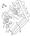
- FIG. 1 depicts a two-component implant which will be inserted into the joint in at least two distinct pieces, which will be assembled in situ (i.e., inside the joint where it will function).
- An anchoring grid 200 will be securely implanted to a prepared bone surface, then a flexible implant subassembly 100 will be inserted into the joint and securely affixed to the anchoring grid 200.
- the flexible implant subassembly 100 shown in FIG. 1 has three distinct layers, or zones. In a preferred embodiment, these three layers are bonded or otherwise fabricated together prior to implantation, in a controlled manufacturing operation; this can ensure proper quality control and maximum strength and stability, and it can reduce the amount of time required for the surgery if the surgeon does not have to carry out an assembly step involving these layers.
- the three layers used in the implant 100 shown in FIG. 1 include a hydrogel bearing layer 110, a "perforated waffle” interface 120, and a bone ingrowth pad 130.
- the hydrogel bearing layer 110 will have a very smooth articulating or bearing surface 112. It should be made of a material such as a fibrous protein and/or polymeric matrix, made of collagen fibers or any of various hydrophilic polymeric fibers. Most hydrogel materials have porosity levels higher than about 90%, often reaching 95% or even higher. Since they are made of hydrophilic fibers and have very high levels of porosity, they will allow water molecules to readily permeate through this layer (or at least through the uppermost portions thereof).
- hydrogel materials can be reinforced, to provide greater strength, by a three-dimensional network of strong woven fibers, as described in more detail in US patent application 09/818,811 by the same Applicant herein; that application was published on February 21, 2002 as unexamined U.S. "A1" application 2002-0022884 (Late published).
- layer 110 can also be covered with an outermost "semi-permeable" membrane, which will allow rapid and facile permeation by water molecules, but not by the much larger polymeric molecules that make up the slippery lubricants that are present in synovial fluid in a mammalian joint.
- flexible implant 100 will have a bone ingrowth pad 130, with an anchoring surface 132 that will be pressed against a bone surface after implantation.
- bone ingrowth pad preferably should promote and induce ingrowth by bony (osseous, calcified) tissue.
- Biocompatible materials that promote bony tissue ingrowth have been developed over the past two decades, and are known to those skilled in the art. Examples include meshes made of biocompatible metallic alloys, which can be "sputter coated", if desired, with calcium-phosphate blends that emulate hydroxyapatite, the crystalline structure that gives bones their hardness.
- a "multi-perforated non-planar interface” component 120 (also referred to herein as a “perforated waffle” layer) can be provided between the relatively soft material of the hydrogel bearing component 110, and the substantially harder material of the bone ingrowth pad 120.
- This type of interface layer 120 is described in more detail in US patent application serial number 10/011,933 , which was published on December 5, 2002 as unexamined U.S. "A1" application 2002-0183845 (Late published).
- a small segment from this type of "perforated waffle” layer, shown in a perspective cutaway view, is provided in FIG. 2 .
- This cutaway drawing depicts two of the numerous "riser bumps" 40 that will be arrayed in a geometric pattern in interface layer 120. Suitable geometric patterns can include rectangular, diamond, or hexagonal arrays, or any other suitable pattern.
- Each riser bump 40 in layer 120 has one or more semi-vertical sides or facets 42 (rising out of the "baseline” or “grid” layer 32), as well as a relatively horizontal upper surface 44 (all references herein to directions such as vertical or horizontal assume that the grid 30 is horizontal).
- the semi-vertical sides 42 preferably should be provided with rounded corners, if any corners are present, to minimize any risk of internal cutting, abrasion, or similar damage (such as, for example, if a patient with one of these implants in a knee or hip falls or must jump from an elevated height, and the knee or hip undergoes an instant of high compression during impact).
- any riser bump 40 should have a flat horizontal upper surface 44, to minimize any risk that a sharp or spiked surface might be pushed into or through the soft material which will overlay it.
- each roughly vertical facet 42, and each horizontal facet 44 has a hole (which can also be called a perforation, orifice, aperture, etc.) passing through it, shown in FIG. 2 as horizontal holes 54, longitudinal holes 56, and transverse holes 58.
- a hole which can also be called a perforation, orifice, aperture, etc.
- riser bumps 40 and the numerous perforations 54-58 which pass through the riser bumps in various directions create a complex non-planar multi-perforated outer surface, in interface layer 120.
- the outer-surface facets 42 and 44 are further supplemented by still more surfaces or facets, on the underside of the interface layer 120.
- interface layer 120 can allow this layer to use fluid flow, within a hydrogel, to redistribute and disseminate, in a more balanced, even, and reinforced manner, the compressive and/or shear forces that are imposed on the articulating surface 112 of the flexible implant subassembly 100.
- the interface layer 120 can be bonded, fused, or otherwise secured to the bone ingrowth pad 130, using any suitable method (such as a chemical adhesive, using targeted heat to soften and melt the appropriate surfaces of two polymeric layers so they will fuse together, using a welding step if the two layers are made of metal, etc.).
- any suitable method such as a chemical adhesive, using targeted heat to soften and melt the appropriate surfaces of two polymeric layers so they will fuse together, using a welding step if the two layers are made of metal, etc.
- both layers may be formed from a single type of material, such as by a combination of techniques that might include, for example: (i) molding a polymeric compound in a mold which is partially occupied, in the bottom layer, by a granular compound (such as salt, sugar, etc.) that subsequently can be dissolved by water or a suitable solvent; (ii) dissolving and removing the granules, thereby creating a porous structure on the bottom layer which promotes cell ingrowth; and, (iii) machining the top layer by means of laser beams, small drill bits, or other suitable means, to create the multiple non-planar perforations on the riser bumps.
- a combination of techniques that might include, for example: (i) molding a polymeric compound in a mold which is partially occupied, in the bottom layer, by a granular compound (such as salt, sugar, etc.) that subsequently can be dissolved by water or a suitable solvent; (ii) dissolving and removing the granules,
- the implant subassembly 100 when fully fabricated, should be sufficiently flexible to allow it to be rolled up into a cylinder, and loaded into an arthroscopic insertion tube. It will be inserted into a joint which has already been prepared, by placement of an anchoring grid 200, as shown in FIG. 1 .
- FIG. 1 illustrates one potential design for an anchoring grid 200, which has a rim 202, a longitudinal runner 204, two transverse runners 206 and 208, and anchoring pins 220.
- Anchoring pins 220 are illustrated in FIG. 1 , to indicate their placement.
- anchoring pins 220 will be not be manufactured as an integral part of anchoring grid 200, since they are likely to interfere with an arthroscopic insertion process if they are fixedly attached to the grid 200. Accordingly, they can be inserted into the joint by the surgeon after the grid 200 is already in place, and driven through accommodating eyelets or similar holes positioned around the periphery of the grid 200.
- pins 220 as part of the anchoring grid 200, by attaching them to remainder of the grid 200 by means of hinges, flaps, or other means that will allow the pins to be rolled up into a tubular form, to allow grid 200 to be squeezed into (and through) an arthroscopic insertion tube.
- the entire implant as disclosed herein can be adapted for use in "open joint" surgery; if prepared for use in that embodiment, the pins can be firmly and rigidly attached to the anchoring layer.
- anchoring grid 200 is shown with "walls" comprising a peripheral rim 202 and runners 204-208.
- walls comprising a peripheral rim 202 and runners 204-208.
- this type of layout may be able to provide several potentially important advantages, because of the way the various wall components, and the internal compartments created by the rim and runners, can interact with bone ingrowth pad 130.
- the reinforced and relatively strong rim 202 can provide any of several potentially useful options for securely attaching the flexible implant 100 to the anchoring grid 200, without having to use one or more anchoring pins or similar devices that would need to penetrate the center portion of the bearing surface 112.
- the runners 204-208 inside rim 202 can help ensure that the rim 202 will return to the proper shape, after being rolled up and forced through an arthroscopic insertion tube.
- a strong cement such as a poly-methyl-methacrylate (PMMA), or a polycarbonate and/or urethane mixture
- PMMA poly-methyl-methacrylate
- urethane mixture a strong cement
- the layout of the anchoring grid 200 can help ensure that during initial recuperation after surgery, before substantial bone ingrowth into the bone ingrowth pad 20 has occurred, the bone ingrowth pad 20 will remain immobilized and stationary, and will not slide or shift on the bone surface that was prepared at the start of the surgery.
- an anchoring grid that will include: (i) a rim, which will interact with anchoring pins that will be driven directly into hard bone material; (ii) one or more internal runners, which will divide the anchoring grid into internal compartments, in an arrangement such as (but not necessarily identical to) the arrangement shown in FIG. 1 . That type of grid may be able to interact with a bone ingrowth pad, in ways that would be difficult to provide using a bone ingrowth pad alone (or bonded to other covering layers).
- the walls which make up rim 202 and runners 204-208 of the anchoring grid 200 are provided with a plurality of orifices (also called apertures, openings, holes, etc.).
- orifices also called apertures, openings, holes, etc.
- Such orifices can be used if animal tests indicate that they promote better anchoring of the implant to the surrounding tissue.
- Such anchoring may be generated by scar tissue, by bony tissue ingrowth, or some combination thereof, depending on the cutting and sculpting steps used in a particular patient, which will determine the size, shape, and positioning of the contact area between the implant and the surrounding tissue.
- an anchoring grid of this nature may provide the option of periodically replacing the bearing pad of an implant, in a manner which is relatively simple and non-traumatic for the patient.
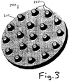
- FIGURE 3 depicts the anchoring surface 310 of a "unitary" implant 300 that can be fabricated as a single unit, in a manufacturing facility, and then rolled up for insertion into a joint through an arthroscopic insertion tube.
- the anchoring surface 310 of implant 300 contains an array of protrusions or "pegs" 320, having a uniform size and a symmetric geometric pattern, so that they can fit in a fairly snug and secure manner into accommodating holes, which can be drilled into a prepared bone surface with the aid of a template that will cause the holes to match the pattern of the pegs 320.
- pegs protrusions
- unitary implant 300 will typically be in a range of about 1 to about 3 centimeters in diameter, and that anchoring pegs 320 will be typically be within a range of about 3 to about 7 mm in diameter.
- the unitary implant 300 can be manufactured as a single item, by creating a fairly steep density/porosity gradient between the hydrogel bearing surface 330, and the anchoring pegs 320.
- the relatively soft and open hydrogel on the bearing surface 330 will have very high porosity, anticipated to be in the range of at least 80% pore space (with less than 20% of its volume taken up by the fibrous matrix).
- the much stiffer and harder anchoring pegs 320 will have much lower porosity, anticipated to be in the range of about 20% or less pore space, with 80% of its volume made of fibers.
- This type of gradient can be created by various known means, which include: (i) using centrifugation, filter pressing, or other compaction or pressurizing techniques to compress fibers into the molding vacancies that will create the anchoring pegs; (ii) sequential crosslinking and/or compaction steps (triggered or controlled by chemicals, radiation, etc.) with additional fibrous material added between different crosslinking steps; or, any other conventional or hereafter-discovered method which is suitable for creating the types of density and compaction gradients that are anticipated herein.
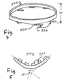
- a "flexible" anchoring rim in a bicomponent system as shown in FIG. 1 , indicates that the rim can be squeezed until its width is about 75% or less of its relaxed width, as shown in FIG. 4.
- FIG. 4 also indicates that anchoring pins 206 have been folded into a relatively flat "trailing” or “inserting” position, by means of hinges or flaps 207 which couple the pins 206 to the rim 202.
- a "flexible" unitary implant 300 can be rolled into a cylindrical arc which has an "angle of displacement" (designated as ⁇ in FIG. 5 ) that is about 110 degrees or less. It is anticipated that the unitary implants disclosed herein will be capable of being rolled into a complete tube.
- a cartilage repair implant must be flexible, in a manner that allows it to be inserted into a joint that is being surgically operated on, through a minimally invasive incision (preferably using arthroscopic devices and methods). This does not mean, however, that the implant must be flexible in the same manner, in all directions.
- an anchoring layer can be made of relatively stiff material (such as metallic strands, or relatively thick and stiff polymeric strands) in one direction (such as the "longitudinal" direction, which is the longest axis of the implant).
- a different and more flexible material can be used in the "transverse" direction, to hold the thicker and stiffer longitudinal strands together.
- This approach can allow an anchoring layer to be curled up fairly tightly in one direction, but not in the other. That type of one-directional or “selective" flexibility can be highly useful for allowing arthroscopic insertion of a rolled-up implant into a joint.
- an anchoring mesh made of a "semi-cured" polymer or similar material which is relatively soft and flexible can be used to provide the anchoring component.
- a treatment such as ultraviolet radiation, through fiber optic cables that terminate in a flattened spatula, with an opaque shield on one side to protect tissue from the UV radiation
- a treatment such as ultraviolet radiation, through fiber optic cables that terminate in a flattened spatula, with an opaque shield on one side to protect tissue from the UV radiation
- the methods that will be used to insert and anchor a flexible implant as disclosed herein may be analogous to unrolling a segment of carpet (which has different layers of backing and tufting) across a floor.
- the flexible implant (which, in most cases, presumably will not be more than a few millimeters thick) will be rolled up into a cylindrical shape, which must be thin enough to be pushed through a minimally invasive incision, using an insertion tube, into a joint that has been prepared to receive the implant.
- the flexible implant will spontaneously unroll, seeking to regain its manufactured shape. As or after it unrolls, it can be positioned, tacked down as needed, and permanently anchored.
- the material can be wrapped around a center core, in a manner which allows it to be unwrapped as it is moved across a bone surface, under the control of the surgeon. As it is unrolled, it is "tacked down" around its periphery by sutures, small pins, or other comparable devices, which can be driven down into the relatively spongy outer bone layer in a controlled manner that prevents them from subsequently causing cutting or abrasion.
- sutures or pins can be connected to the implant by suitable means, such as small eyelets or loops that extend downward from bone ingrowth pad 130 or from any woven fibrous material that is embedded in a soft outer layer 110.
- an implant after an implant has been fully unrolled, positioned, and tacked down, it can be permanently anchored to the bone.
- the anchoring layer does not need to be highly flexible, to a point of allowing the device to be rolled up into a tight spiral. So long as sufficient flexibility is provided in the anchoring layer to allow the implant to be flexed into a shape that is not as wide as the implant will be after it is fully anchored (for example, if two opposed sides or ends of the device can be curled toward each other, to form a simple U-shaped or similar configuration), then that degree of flexibility will allow the implant to be inserted through a "minimally invasive" incision, as that term is interpreted and applied. In determining the value of this type of implant in surgery on a damaged joint, the question is not whether a flexible device will fit through a standard, conventional arthroscopic insertion tube.
Abstract
Description
- This invention is in the field of surgery, and relates to surgical implants for replacing damaged cartilage in joints such as knees, hips, and shoulders.
- Numerous efforts have been made to create various types of surgical methods and implants that can repair or replace damaged or diseased cartilage segments, in mammalian joints such as knees, hips, and shoulders. Those efforts generally can be divided into two categories: (1) resorbable implants, made of materials that will dissolve over a span of weeks or months and be replaced by natural biological materials; and, (2) non-resorbable implants, designed to remain in a repaired joint for numerous years, and preferably for the entire remaining life of the patient.
- Most types of resorbable implants are designed for regeneration of cartilage by living cells, rather than for replacing cartilage by synthetic polymers or other non-living materials. Cartilage regeneration efforts using resorbable implants usually involve transplantation of chondrocyte and/or mesenchymal cells, and the resorbable implants are designed to shelter and nurture the transplanted cells, allowing them to be "seeded" into the resorbable implant a week or so prior to implantation, thereby giving the cells a "headstart" before they are transplanted into the damaged joint.
- At the current time, the devices discussed herein fall into the category of non-resorbable implants, made of synthetic materials and designed to remain in a joint for years, and preferably for the remaining life of the patient. These implants will be used to replace, rather than regenerate, a cartilage segment that has become damaged or diseased. Accordingly, this current invention, as described and claimed below, is limited to non-resorbable implants, designed for replacement rather than regeneration of damaged cartilage.
- Nevertheless, it should be recognized that, as research on these devices progresses, it may also be possible to adapt these devices for use in: (i) implants that use resorbable materials; and/or, (ii) cell-transplanting operations, designed to promote the regeneration of cartilage by transplanted cells. Accordingly, this current invention is not intended to close off and deny those possibilities; instead, this invention is intended as a focused and targeted step forward in the development of non-resorbable implants, with the understanding that this development might also be extendible, in the future, to a different and distinct approach to cartilage repair.
- In a similar manner, at the current time, any references herein to "implant", "device", or similar terms are limited to devices that will be implanted surgically, into a mammalian joint, to repair or replace a segment of hyaline cartilage. As known to those skilled in the art, hyaline cartilage is the term used to describe the type of cartilage that covers the condyles (rounded ends) of articulating bone surfaces, in joints such as knees, hips, shoulders, fingers, wrists, etc.
- Two other types of cartilage (known as elastic cartilage, and fibrocartilage) also exist in mammals, and are present in the ears, nose, windpipe, etc. If desired, the invention disclosed herein can be adapted for use in repairing elastic cartilage and/or fibrocartilage. However, it should be recognized that, because of the compressive and shear forces involved, replacing damaged hyaline cartilage in load-bearing joints (especially the knees, hips, and shoulders) is much more difficult than replacing cartilage in the ears, nose, or other locations in the body. Accordingly, the only prior art which is regarded as relevant herein involves efforts to repair damaged hyaline cartilage knees, hips, shoulders, or ankles. Any other type of cartilage repair (including repair of damaged cartilage in finger joints) will not have to meet or satisfy the types of mechanical stresses that will be placed on cartilage segments in joints such as the knees, hips, or shoulders.
- One goal of this invention is to provide non-resorbable devices that can be inserted into a damaged or diseased joint using "minimally invasive" methods and tools, which includes arthroscopic methods and tools. However, it should be recognized that some of the devices disclosed herein may be able to provide improved implants that can be implanted using older surgical methods (often called "classical" or "open joint" methods). In addition, it should be recognized that there is not always a clear dividing line between open joint methods, and minimally invasive methods, since any competent surgeon will always minimize the amount of cutting and other damage and disruption to muscles, ligaments, blood vessels, and other tissues, in any surgical operation, in view of the needs of the operation and the patient.
- Accordingly, any use herein of broad terms such as "surgery" or "surgical" are deemed to include arthroscopic and other minimally invasive methods; and, whenever use is made of a narrow term such as "arthroscopic", it should be realized that arthroscopic use is the primary goal of this invention, but the devices disclosed herein may also be adapted for use with other (classical, open joint) surgical methods.
- Background information on non-resorbable implants in the prior art is contained in various medical textbooks, such as Campbell's Operative Orthopedics, and in numerous articles and patents, such as
US patent 6,132,468 (by the same inventor herein) and other patents and articles cited therein. The state of the art according toUS-A-2001/0039455 is acknowledged in the preamble of claim 1. - In his ongoing efforts to develop improved implants for repairing or replacing cartilage, the Applicant has realized that a particular combination of components, arranged in a particular manner as disclosed below, can provide an improved device with a combination of highly useful traits and advantages. Such devices can be implanted entirely through arthroscopic or minimally-invasive incisions, to minimize damage and disruption to surrounding tissues and vasculature. After implantation, these devices can provide a combination of highly advantageous traits, on both the "anchoring" side (i.e., the side of an implant which presses against a supporting bone structure, such as a femoral or tibial condyle, in a knee) and the "articulating" side (i.e., the side which is exposed to synovial fluid in a joint and which will slide and rub against another cartilage or implant surface in the joint).
- Accordingly, one object of this invention is to disclose an improved non-resorbable implant for repairing or replacing damaged or diseased cartilage in a joint such as a knee, wrist, ankle, or finger, and possibly in a ball-and-socket joint such as a hip or shoulder.
- Another object of this invention is to disclose an improved non-resorbable implant for repairing or replacing cartilage, having both (i) a relatively pliant and non-rigid "bearing surface" which emulates the articulating surface of a segment of natural cartilage, and (ii) an anchoring portion which is sufficiently flexible to allow it to be inserted into a joint, during surgery, through an arthroscopic insertion tube.
- Another object of this invention is to disclose an improved non-resorbable implant for repairing or replacing cartilage, which is thin enough to allow it to be rolled up into a cylindrical shape that can be inserted into a joint through an arthroscopic insertion tube, and then unrolled, inside the joint, in a manner which allows it to be pinned or otherwise anchored to a prepared bone surface.
- Another object of this invention is to disclose an improved non-resorbable implant for repairing or replacing cartilage, made of components that are small enough to be inserted into a joint via arthroscopic methods, and then assembled in situ, inside the joint, to form a complete and functional implant.
- These and other objects of the invention will become more apparent through the following summary, drawings, and description.
- A non-resorbable implant for repairing or replacing damaged or diseased cartilage in a mammalian joint (such as a knee) is disclosed. This implant uses a relatively soft and bendable "bearing surface", which is bonded or otherwise coupled (preferably through one or more intermediate layers or components that provide greater strength) to a flexible anchoring component, such as a rim or grid component, or a porous non-planar molded layer. All components which make up the implant should be flexible, so that the implant (or each component, for a device that is assembled in situ) can be rolled up and surgically inserted into a joint through a minimally-invasive incision, preferably by arthroscopic means. In one embodiment, a flexible anchoring component which does not contain a bearing surface is inserted into a damaged joint through an insertion tube, opened up to its final shape inside the joint, and anchored to a prepared bone surface, using pins, cement, or other suitable means. A component with the bearing surface is then inserted into the joint, unrolled or unfolded by the surgeon, and affixed to the anchoring component. In an alternate embodiment, a unitary implant, having a gel-type bearing surface with high porosity on the articulating side, and having anchoring pegs made of the same or a compatible material but with lower porosity and greater strength on the opposed anchoring side, can be used. In either structure, the anchoring side should be made of a material which encourages ingrowth of osseous (bony, calcified) tissue, for a stronger and more permanent fixation to the supporting bone.
-
-
FIGURE 1 depicts a flexible cartilage-replacing implant made of components that are inserted separately into a joint, and then assembled in situ (inside the joint). -
FIGURE 2 is a cutaway perspective view of a small segment of a "perforated waffle" layer which can be used to provide a stronger interface between a soft hydrogel layer, and a much stiffer and harder anchoring layer. -
FIGURE 3 depicts a unitary implant, made of a hydrophilic fibrous matrix which has a density/porosity gradient that allows the smooth articulating surface to be a high-porosity hydrogel, while the anchoring pegs have much less porosity and are much stiffer and stronger. -
FIGURE 4 depicts a flexible rim of a bi-component anchoring grid, which has been squeezed to give it a smaller width, and which has had its anchoring pins rotated to a trailing/inserting position by means of hinges or flexible flaps which attach the pins to the rim. -
FIGURE 5 depicts a single-component implant as shown inFIG. 3 , which has been rolled into a cylindrical arc having an angle of displacement designated as α. - To illustrate the preferred embodiments of this invention, it is assumed that an orthopedic surgeon will use a flexible implant as disclosed herein to treat a patient who is suffering from "
Grade 4 chondromalacia" in a knee joint. Upon doing an arthroscopic analysis, the surgeon realizes that part of a medial femoral runner, and part of the medial tibial plateau which rubs against the femoral runner, have both become seriously abraded. On each of those two surfaces, a generally round area of cartilage has been completely worn away, exposing the underlying bone, and generating substantial pain and discomfort which caused the patient to have the knee examined. Each area of denuded bone is surrounded by roughly concentric rings of Grade 3 chondromalacia (which is less severe, with some cartilage remaining over the bone), then Grade 2 (moderate) chondromalacia, then Grade 1 (shallow surface) chondromalacia, and with generally undamaged areas of cartilage surrounding those abraded areas. - Using arthroscopic tools, the surgeon will prepare a hard bone surface, usually in a roughly circular or elliptical area, by removing an area of cartilage from each of the affected bones (the femur, and the tibia). The exposed "spongiform" bone surfaces are then "freshened" by abrading. When those bone surfaces have been prepared, the surgeon is ready to insert two implants, one for each exposed bone surface. As used herein, any references to "hard bone surface" exclude the intramedullary canal portion of a bone, or the portion of a bone which contains the relatively soft internal portion that contains the bone marrow. Most "hard bone surface" preparations that will provide the strong anchoring attachments needed for a knee or similar joint repair will target a portion of the hard bone structure known as a "subchondral plate".
- The implants disclosed herein can be manufactured in a variety of sizes and shapes. To ensure that the implant used will fit or at least closely aproximate the exposed bone surface area, the surgeon can take any of several steps, including: (i) choosing a pre-manufactured implant that is close to the final desired shape; (ii) trimming the implant as needed to ensure the best possible fit; and (iii) using a small, easily manipulated piece of material (which may be opaque and brightly colored for high visual contrast, or which may have a printed sizing grid on it) as a fitting device to help the surgeon check the exact size and shape of the prepared bone surface. By carrying out the process carefully, a skilled surgeon can modify the implant and/or the bone surface, to ensure a close-fitting accommodation between the two.
- If desired, the implant can have a curved (rather than flat or planar) overall shape, to help it more closely conform to the bone surface it will be emplaced upon and the cartilage surface that is being replaced. Unless designed otherwise for a specific purpose, it is generally anticipated that each implant typically will have a thickness of several millimeters.
- Each implant will have an "articulating" or "bearing" surface on one side, and an "anchoring" surface on the other side. After an implant has been installed, the anchoring surface will be pressed against the supporting bone, and the articulating or bearing surface will remain exposed to the synovial fluid which lubricates the joint. When the patient walks, the bearing surface on a femoral implant will rub and slide against the bearing surface on a tibial implant.
- It is anticipated that, for most patients, both a femoral runner implant and a tibial plateau implant will be installed at the same time, in the same operation. Because cartilage is a relatively soft natural form of hydrogel, as soon as one cartilage surface in a joint becomes damaged, it becomes roughened in a way that causes it to begin abrading and damaging the cartilage surface that rubs against it. By the
time grade 4 chondromalacia leads to exposed bone, both of the two cartilage surfaces that rub and slide against each other in that joint compartment will be badly damaged. -
FIG. 1 depicts a two-component implant which will be inserted into the joint in at least two distinct pieces, which will be assembled in situ (i.e., inside the joint where it will function). An anchoring grid 200 will be securely implanted to a prepared bone surface, then aflexible implant subassembly 100 will be inserted into the joint and securely affixed to the anchoring grid 200. - The
flexible implant subassembly 100 shown inFIG. 1 has three distinct layers, or zones. In a preferred embodiment, these three layers are bonded or otherwise fabricated together prior to implantation, in a controlled manufacturing operation; this can ensure proper quality control and maximum strength and stability, and it can reduce the amount of time required for the surgery if the surgeon does not have to carry out an assembly step involving these layers. - The three layers used in the
implant 100 shown inFIG. 1 include ahydrogel bearing layer 110, a "perforated waffle" interface 120, and abone ingrowth pad 130. - The
hydrogel bearing layer 110 will have a very smooth articulating or bearingsurface 112. It should be made of a material such as a fibrous protein and/or polymeric matrix, made of collagen fibers or any of various hydrophilic polymeric fibers. Most hydrogel materials have porosity levels higher than about 90%, often reaching 95% or even higher. Since they are made of hydrophilic fibers and have very high levels of porosity, they will allow water molecules to readily permeate through this layer (or at least through the uppermost portions thereof). If desired, hydrogel materials can be reinforced, to provide greater strength, by a three-dimensional network of strong woven fibers, as described in more detail inUS patent application 09/818,811 U.S. "A1" application 2002-0022884 (Late published). If desired,layer 110 can also be covered with an outermost "semi-permeable" membrane, which will allow rapid and facile permeation by water molecules, but not by the much larger polymeric molecules that make up the slippery lubricants that are present in synovial fluid in a mammalian joint. - On its opposed side,
flexible implant 100 will have abone ingrowth pad 130, with an anchoringsurface 132 that will be pressed against a bone surface after implantation. In order to promote solid and stable anchoring, bone ingrowth pad preferably should promote and induce ingrowth by bony (osseous, calcified) tissue. Biocompatible materials that promote bony tissue ingrowth have been developed over the past two decades, and are known to those skilled in the art. Examples include meshes made of biocompatible metallic alloys, which can be "sputter coated", if desired, with calcium-phosphate blends that emulate hydroxyapatite, the crystalline structure that gives bones their hardness. - In a preferred embodiment, a "multi-perforated non-planar interface" component 120 (also referred to herein as a "perforated waffle" layer) can be provided between the relatively soft material of the
hydrogel bearing component 110, and the substantially harder material of the bone ingrowth pad 120. This type of interface layer 120 is described in more detail inUS patent application serial number 10/011,933 , which was published on December 5, 2002 as unexaminedU.S. "A1" application 2002-0183845 (Late published). A small segment from this type of "perforated waffle" layer, shown in a perspective cutaway view, is provided inFIG. 2 . This cutaway drawing depicts two of the numerous "riser bumps" 40 that will be arrayed in a geometric pattern in interface layer 120. Suitable geometric patterns can include rectangular, diamond, or hexagonal arrays, or any other suitable pattern. - Each
riser bump 40 in layer 120 has one or more semi-vertical sides or facets 42 (rising out of the "baseline" or "grid" layer 32), as well as a relatively horizontal upper surface 44 (all references herein to directions such as vertical or horizontal assume that thegrid 30 is horizontal). Thesemi-vertical sides 42 preferably should be provided with rounded corners, if any corners are present, to minimize any risk of internal cutting, abrasion, or similar damage (such as, for example, if a patient with one of these implants in a knee or hip falls or must jump from an elevated height, and the knee or hip undergoes an instant of high compression during impact). For similar reasons, anyriser bump 40 should have a flat horizontalupper surface 44, to minimize any risk that a sharp or spiked surface might be pushed into or through the soft material which will overlay it. - As shown in
FIG. 2 , each roughlyvertical facet 42, and eachhorizontal facet 44, has a hole (which can also be called a perforation, orifice, aperture, etc.) passing through it, shown inFIG. 2 as horizontal holes 54,longitudinal holes 56, andtransverse holes 58. - Acting together, riser bumps 40 and the numerous perforations 54-58 which pass through the riser bumps in various directions create a complex non-planar multi-perforated outer surface, in interface layer 120. In addition, as can be seen from the visible "inner walls" or "underside walls" 45, shown in
FIG. 2 , the outer-surface facets - All of those surfaces or facets are exposed and accessible to the water molecules in a gel compound. Therefore, all of those surfaces or facets can resist fluid pressure which is imposed on those facets. In this manner, the complex surface geometry of interface layer 120 can allow this layer to use fluid flow, within a hydrogel, to redistribute and disseminate, in a more balanced, even, and reinforced manner, the compressive and/or shear forces that are imposed on the articulating
surface 112 of theflexible implant subassembly 100. - The interface layer 120 can be bonded, fused, or otherwise secured to the
bone ingrowth pad 130, using any suitable method (such as a chemical adhesive, using targeted heat to soften and melt the appropriate surfaces of two polymeric layers so they will fuse together, using a welding step if the two layers are made of metal, etc.). Alternately, it may be possible to fabricate both layers from a single type of material, such as by a combination of techniques that might include, for example: (i) molding a polymeric compound in a mold which is partially occupied, in the bottom layer, by a granular compound (such as salt, sugar, etc.) that subsequently can be dissolved by water or a suitable solvent; (ii) dissolving and removing the granules, thereby creating a porous structure on the bottom layer which promotes cell ingrowth; and, (iii) machining the top layer by means of laser beams, small drill bits, or other suitable means, to create the multiple non-planar perforations on the riser bumps. - The
implant subassembly 100, when fully fabricated, should be sufficiently flexible to allow it to be rolled up into a cylinder, and loaded into an arthroscopic insertion tube. It will be inserted into a joint which has already been prepared, by placement of an anchoring grid 200, as shown inFIG. 1 . -
FIG. 1 illustrates one potential design for an anchoring grid 200, which has a rim 202, alongitudinal runner 204, twotransverse runners 206 and 208, and anchoring pins 220. - Anchoring pins 220 are illustrated in
FIG. 1 , to indicate their placement. In one preferred embodiment, anchoring pins 220 will be not be manufactured as an integral part of anchoring grid 200, since they are likely to interfere with an arthroscopic insertion process if they are fixedly attached to the grid 200. Accordingly, they can be inserted into the joint by the surgeon after the grid 200 is already in place, and driven through accommodating eyelets or similar holes positioned around the periphery of the grid 200. - In an alternate preferred embodiment, it may be possible to manufacture pins 220 as part of the anchoring grid 200, by attaching them to remainder of the grid 200 by means of hinges, flaps, or other means that will allow the pins to be rolled up into a tubular form, to allow grid 200 to be squeezed into (and through) an arthroscopic insertion tube. In addition, as noted above, the entire implant as disclosed herein can be adapted for use in "open joint" surgery; if prepared for use in that embodiment, the pins can be firmly and rigidly attached to the anchoring layer.
- In the embodiment shown in
FIG. 1 , anchoring grid 200 is shown with "walls" comprising a peripheral rim 202 and runners 204-208. For purposes of this disclosure, it is believed that this type of layout may be able to provide several potentially important advantages, because of the way the various wall components, and the internal compartments created by the rim and runners, can interact withbone ingrowth pad 130. - As one example of a potential advantage of this layout, the reinforced and relatively strong rim 202 can provide provide any of several potentially useful options for securely attaching the
flexible implant 100 to the anchoring grid 200, without having to use one or more anchoring pins or similar devices that would need to penetrate the center portion of the bearingsurface 112. In addition, the runners 204-208 inside rim 202 can help ensure that the rim 202 will return to the proper shape, after being rolled up and forced through an arthroscopic insertion tube. Third, it may be possible to use a strong cement (such as a poly-methyl-methacrylate (PMMA), or a polycarbonate and/or urethane mixture) to chemically bond an anchoring grid 200 to a bone, in a manner which will prevent the cement from clogging and interfering with the desired porosity of the underside ofbone ingrowth pad 130. And fourth, the layout of the anchoring grid 200 can help ensure that during initial recuperation after surgery, before substantial bone ingrowth into the bone ingrowth pad 20 has occurred, the bone ingrowth pad 20 will remain immobilized and stationary, and will not slide or shift on the bone surface that was prepared at the start of the surgery. - These and other factors suggest that one embodiment of the implant disclosed herein, which will be preferred for at least some patients, is likely to use an anchoring grid that will include: (i) a rim, which will interact with anchoring pins that will be driven directly into hard bone material; (ii) one or more internal runners, which will divide the anchoring grid into internal compartments, in an arrangement such as (but not necessarily identical to) the arrangement shown in
FIG. 1 . That type of grid may be able to interact with a bone ingrowth pad, in ways that would be difficult to provide using a bone ingrowth pad alone (or bonded to other covering layers). - In the embodiment shown in
FIG. 1 , the walls which make up rim 202 and runners 204-208 of the anchoring grid 200 are provided with a plurality of orifices (also called apertures, openings, holes, etc.). Such orifices (which may be filled with permeable material that promotes bone tissue ingrowth) can be used if animal tests indicate that they promote better anchoring of the implant to the surrounding tissue. Such anchoring may be generated by scar tissue, by bony tissue ingrowth, or some combination thereof, depending on the cutting and sculpting steps used in a particular patient, which will determine the size, shape, and positioning of the contact area between the implant and the surrounding tissue. - It should also be noted that an anchoring grid of this nature may provide the option of periodically replacing the bearing pad of an implant, in a manner which is relatively simple and non-traumatic for the patient.
- In contrast to the two-component system described above, in which an anchoring grid 200 is inserted into a joint and firmly anchored to a bone before the remainder of the
implant 100 is inserted and affixed to the anchoring grid,FIGURE 3 depicts the anchoringsurface 310 of a "unitary"implant 300 that can be fabricated as a single unit, in a manufacturing facility, and then rolled up for insertion into a joint through an arthroscopic insertion tube. - The anchoring
surface 310 ofimplant 300 contains an array of protrusions or "pegs" 320, having a uniform size and a symmetric geometric pattern, so that they can fit in a fairly snug and secure manner into accommodating holes, which can be drilled into a prepared bone surface with the aid of a template that will cause the holes to match the pattern of thepegs 320. - It is anticipated that a common size for
unitary implant 300 will typically be in a range of about 1 to about 3 centimeters in diameter, and that anchoring pegs 320 will be typically be within a range of about 3 to about 7 mm in diameter. - The
unitary implant 300 can be manufactured as a single item, by creating a fairly steep density/porosity gradient between the hydrogel bearing surface 330, and the anchoring pegs 320. The relatively soft and open hydrogel on the bearing surface 330 will have very high porosity, anticipated to be in the range of at least 80% pore space (with less than 20% of its volume taken up by the fibrous matrix). By contrast, the much stiffer and harder anchoring pegs 320 will have much lower porosity, anticipated to be in the range of about 20% or less pore space, with 80% of its volume made of fibers. This type of gradient can be created by various known means, which include: (i) using centrifugation, filter pressing, or other compaction or pressurizing techniques to compress fibers into the molding vacancies that will create the anchoring pegs; (ii) sequential crosslinking and/or compaction steps (triggered or controlled by chemicals, radiation, etc.) with additional fibrous material added between different crosslinking steps; or, any other conventional or hereafter-discovered method which is suitable for creating the types of density and compaction gradients that are anticipated herein. - As used herein, a "flexible" anchoring rim, in a bicomponent system as shown in
FIG. 1 , indicates that the rim can be squeezed until its width is about 75% or less of its relaxed width, as shown inFIG. 4. FIG. 4 also indicates that anchoringpins 206 have been folded into a relatively flat "trailing" or "inserting" position, by means of hinges or flaps 207 which couple thepins 206 to the rim 202. - As used herein, a "flexible"
unitary implant 300 can be rolled into a cylindrical arc which has an "angle of displacement" (designated as α inFIG. 5 ) that is about 110 degrees or less. It is anticipated that the unitary implants disclosed herein will be capable of being rolled into a complete tube. - These (or greater) degrees of flexibility can help minimize tissue disruption as an implant is being inserted into a joint.
- To be useful as disclosed herein, a cartilage repair implant must be flexible, in a manner that allows it to be inserted into a joint that is being surgically operated on, through a minimally invasive incision (preferably using arthroscopic devices and methods). This does not mean, however, that the implant must be flexible in the same manner, in all directions. Instead, as one example, an anchoring layer can be made of relatively stiff material (such as metallic strands, or relatively thick and stiff polymeric strands) in one direction (such as the "longitudinal" direction, which is the longest axis of the implant). A different and more flexible material (such as nylon strands, or substantially thinner polymeric strands) can be used in the "transverse" direction, to hold the thicker and stiffer longitudinal strands together. This approach can allow an anchoring layer to be curled up fairly tightly in one direction, but not in the other. That type of one-directional or "selective" flexibility can be highly useful for allowing arthroscopic insertion of a rolled-up implant into a joint.
- Various other approaches can also (or alternately) be used, to provide a desired and/or manipulable type or degree of flexibility during the implant insertion procedure. As one example, an anchoring mesh made of a "semi-cured" polymer or similar material which is relatively soft and flexible can be used to provide the anchoring component. In its soft and flexible pre-surgical form, it can be rolled up into a relatively tight cylinder or spiral. After it has been inserted into a joint, unrolled, and tacked down to a bone, it can be subjected to a treatment (such as ultraviolet radiation, through fiber optic cables that terminate in a flattened spatula, with an opaque shield on one side to protect tissue from the UV radiation) that will cause it to become substantially stiffer and harder.
- In some respects, the methods that will be used to insert and anchor a flexible implant as disclosed herein may be analogous to unrolling a segment of carpet (which has different layers of backing and tufting) across a floor.
- Briefly, the flexible implant (which, in most cases, presumably will not be more than a few millimeters thick) will be rolled up into a cylindrical shape, which must be thin enough to be pushed through a minimally invasive incision, using an insertion tube, into a joint that has been prepared to receive the implant. In one embodiment, as it is pushed out of the end of the tube, it will spontaneously unroll, seeking to regain its manufactured shape. As or after it unrolls, it can be positioned, tacked down as needed, and permanently anchored.
- In an alternate embodiment, the material can be wrapped around a center core, in a manner which allows it to be unwrapped as it is moved across a bone surface, under the control of the surgeon. As it is unrolled, it is "tacked down" around its periphery by sutures, small pins, or other comparable devices, which can be driven down into the relatively spongy outer bone layer in a controlled manner that prevents them from subsequently causing cutting or abrasion. Such sutures or pins can be connected to the implant by suitable means, such as small eyelets or loops that extend downward from
bone ingrowth pad 130 or from any woven fibrous material that is embedded in a softouter layer 110. - Regardless of which method of unrolling is used, after an implant has been fully unrolled, positioned, and tacked down, it can be permanently anchored to the bone.
- It should be noted that the anchoring layer does not need to be highly flexible, to a point of allowing the device to be rolled up into a tight spiral. So long as sufficient flexibility is provided in the anchoring layer to allow the implant to be flexed into a shape that is not as wide as the implant will be after it is fully anchored (for example, if two opposed sides or ends of the device can be curled toward each other, to form a simple U-shaped or similar configuration), then that degree of flexibility will allow the implant to be inserted through a "minimally invasive" incision, as that term is interpreted and applied. In determining the value of this type of implant in surgery on a damaged joint, the question is not whether a flexible device will fit through a standard, conventional arthroscopic insertion tube. Instead, the pertinent question is whether this new type of flexible implant can be inserted through a smaller incision (which will cause less tissue and blood vessel damage and disruption, thereby allowing faster recovery with less pain and scarring) than would be required for a non-flexible implant of the same size.
- Thus, there has been shown and described a new and useful means for creating improved implants for repairing cartilage in joints such as knees. Although this invention has been exemplified for purposes of illustration and description by reference to certain specific embodiments, it will be apparent to those skilled in the art that various modifications, alterations, and equivalents of the illustrated examples are possible. Any such changes which derive directly from the teachings herein, and which do not depart from the scope of the invention, are deemed to be covered by this invention.
Claims (5)
- A surgical implant for repairing damaged hyaline cartilage in a mammalian joint, comprising:an anchoring layer (130) that is designed to press against a prepared bone surface area from which cartilage has been removed,a bearing surface layer (110), said bearing surface layer is made of a flexible hydrophilic polymer which will provide a smooth and lubricious articulating surface (112) that resembles hyaline cartilage after implantation of the surgical implant into a mammalian joint,characterised in that
anchoring protrusions are provided,
said anchoring protrusions being suited to extend into accommodating bone in a manner which resists shear stresses imposed on the surgical implant after surgical implantation into a mammalian joint;
the anchoring layer (130) is provided with at least one of said anchoring protrusions (200)
or
is designed to interact with at least one of said anchoring protrusions,
further characterised in that the surgical implant is a flexible surgical implant, so that the implant can be rolled up and surgically inserted in a joint through a minimally-invasive incision by arthroscopic means. - The flexible surgical implant of Claim 1, wherein the bearing surface layer (110) comprises a hydrogel.
- The flexible surgical implant of Claim 1, wherein a plurality of anchoring components (200) that extend below the prepared bone surface are used to enable the surgical implant to resist shear stresses that will be encountered in the joint being repaired.
- The flexible surgical implant of Claim 1, wherein the surgical implant is sufficiently flexible to allow said implant to be flexed into an elongated shape having a width of about 75% or less of its normal relaxed width.
- The flexible surgical implant of Claim 1, wherein the surgical implant is sufficiently flexible to allow it to be rolled into a cylindrical arc wherein the opposed edges of the arc have an angular displacement of 110 degrees or less.
Applications Claiming Priority (3)
| Application Number | Priority Date | Filing Date | Title |
|---|---|---|---|
| US10/071,930 US9050192B2 (en) | 2001-02-05 | 2002-02-08 | Cartilage repair implant with soft bearing surface and flexible anchoring device |
| US71930 | 2002-02-08 | ||
| PCT/US2003/003664 WO2003065932A1 (en) | 2002-02-08 | 2003-02-08 | Cartilage repair implant with soft bearing surface and flexible anchoring device |
Publications (3)
| Publication Number | Publication Date |
|---|---|
| EP1513469A1 EP1513469A1 (en) | 2005-03-16 |
| EP1513469A4 EP1513469A4 (en) | 2006-04-26 |
| EP1513469B1 true EP1513469B1 (en) | 2010-01-13 |
Family
ID=27732291
Family Applications (1)
| Application Number | Title | Priority Date | Filing Date |
|---|---|---|---|
| EP20030737692 Expired - Lifetime EP1513469B1 (en) | 2002-02-08 | 2003-02-08 | Cartilage repair implant with soft bearing surface and flexible anchoring device |
Country Status (7)
| Country | Link |
|---|---|
| US (1) | US9050192B2 (en) |
| EP (1) | EP1513469B1 (en) |
| AT (1) | ATE454863T1 (en) |
| AU (1) | AU2003210896A1 (en) |
| DE (1) | DE60330962D1 (en) |
| ES (1) | ES2341709T3 (en) |
| WO (1) | WO2003065932A1 (en) |
Families Citing this family (443)
| Publication number | Priority date | Publication date | Assignee | Title |
|---|---|---|---|---|
| US20050209703A1 (en) * | 1999-04-02 | 2005-09-22 | Fell Barry M | Surgically implantable prosthetic system |
| US7491235B2 (en) * | 1999-05-10 | 2009-02-17 | Fell Barry M | Surgically implantable knee prosthesis |
| US7297161B2 (en) * | 1999-05-10 | 2007-11-20 | Fell Barry M | Surgically implantable knee prosthesis |
| US7338524B2 (en) * | 1999-05-10 | 2008-03-04 | Fell Barry M | Surgically implantable knee prosthesis |
| US20050033424A1 (en) * | 1999-05-10 | 2005-02-10 | Fell Barry M. | Surgically implantable knee prosthesis |
| DE60041670D1 (en) * | 1999-12-03 | 2009-04-09 | Univ Leeds | Restoration of damaged tissue |
| US20060147332A1 (en) | 2004-12-30 | 2006-07-06 | Howmedica Osteonics Corp. | Laser-produced porous structure |
| US7537664B2 (en) | 2002-11-08 | 2009-05-26 | Howmedica Osteonics Corp. | Laser-produced porous surface |
| US6994730B2 (en) * | 2003-01-31 | 2006-02-07 | Howmedica Osteonics Corp. | Meniscal and tibial implants |
| US20070084897A1 (en) | 2003-05-20 | 2007-04-19 | Shelton Frederick E Iv | Articulating surgical stapling instrument incorporating a two-piece e-beam firing mechanism |
| US9060770B2 (en) | 2003-05-20 | 2015-06-23 | Ethicon Endo-Surgery, Inc. | Robotically-driven surgical instrument with E-beam driver |
| GB0322145D0 (en) * | 2003-09-22 | 2003-10-22 | Howmedica Internat S De R L | Apparatus for use in the regeneration of structured human tissue |
| US7666230B2 (en) * | 2003-12-08 | 2010-02-23 | Depuy Products, Inc. | Implant device for cartilage regeneration in load bearing articulation regions |
| WO2005077304A1 (en) | 2004-02-06 | 2005-08-25 | Georgia Tech Research Corporation | Load bearing biocompatible device |
| CA2558623C (en) | 2004-02-06 | 2013-04-16 | Georgia Tech Research Corporation | Surface directed cellular attachment |
| US20050278025A1 (en) * | 2004-06-10 | 2005-12-15 | Salumedica Llc | Meniscus prosthesis |
| US11896225B2 (en) | 2004-07-28 | 2024-02-13 | Cilag Gmbh International | Staple cartridge comprising a pan |
| US8215531B2 (en) | 2004-07-28 | 2012-07-10 | Ethicon Endo-Surgery, Inc. | Surgical stapling instrument having a medical substance dispenser |
| US20090088846A1 (en) * | 2007-04-17 | 2009-04-02 | David Myung | Hydrogel arthroplasty device |
| US7235592B2 (en) | 2004-10-12 | 2007-06-26 | Zimmer Gmbh | PVA hydrogel |
| WO2006060555A1 (en) * | 2004-11-30 | 2006-06-08 | Mansmann Kevin A | Anchoring systems and interfaces for flexible surgical implants for replacing cartilage |
| US7825083B2 (en) * | 2005-02-10 | 2010-11-02 | Spine Wave, Inc. | Synovial fluid barrier |
| US8017139B2 (en) | 2005-02-23 | 2011-09-13 | Zimmer Technology, Inc. | Blend hydrogels and methods of making |
| US20060224244A1 (en) * | 2005-03-31 | 2006-10-05 | Zimmer Technology, Inc. | Hydrogel implant |
| US20060235542A1 (en) | 2005-04-15 | 2006-10-19 | Zimmer Technology, Inc. | Flexible segmented bearing implant |
| US7291169B2 (en) * | 2005-04-15 | 2007-11-06 | Zimmer Technology, Inc. | Cartilage implant |
| GB0514358D0 (en) * | 2005-07-13 | 2005-08-17 | Smith & Nephew | Implants for tissue repair |
| US20090017096A1 (en) * | 2005-08-15 | 2009-01-15 | Anthony Lowman | Porous non-biodegradable hydrogel admixed with a chemoattractant for tissue replacement |
| EP1924208B1 (en) * | 2005-08-31 | 2012-08-22 | Zimmer GmbH | Femur Implant |
| US11484312B2 (en) | 2005-08-31 | 2022-11-01 | Cilag Gmbh International | Staple cartridge comprising a staple driver arrangement |
| US10159482B2 (en) | 2005-08-31 | 2018-12-25 | Ethicon Llc | Fastener cartridge assembly comprising a fixed anvil and different staple heights |
| US7669746B2 (en) | 2005-08-31 | 2010-03-02 | Ethicon Endo-Surgery, Inc. | Staple cartridges for forming staples having differing formed staple heights |
| US7934630B2 (en) | 2005-08-31 | 2011-05-03 | Ethicon Endo-Surgery, Inc. | Staple cartridges for forming staples having differing formed staple heights |
| US11246590B2 (en) | 2005-08-31 | 2022-02-15 | Cilag Gmbh International | Staple cartridge including staple drivers having different unfired heights |
| US9237891B2 (en) | 2005-08-31 | 2016-01-19 | Ethicon Endo-Surgery, Inc. | Robotically-controlled surgical stapling devices that produce formed staples having different lengths |
| US20070088444A1 (en) * | 2005-10-13 | 2007-04-19 | Robert A Hodorek | Method for repairing a bone defect using a formable implant which hardens in vivo |
| US20070100460A1 (en) * | 2005-10-27 | 2007-05-03 | Rhodes James M | Orthopaedic implant systems with anti-abrasion studs |
| US8216319B2 (en) * | 2005-10-27 | 2012-07-10 | Depuy Products, Inc. | Method of repairing a knee joint |
| US8403985B2 (en) * | 2005-11-02 | 2013-03-26 | Zimmer, Inc. | Joint spacer implant |
| US20070106317A1 (en) | 2005-11-09 | 2007-05-10 | Shelton Frederick E Iv | Hydraulically and electrically actuated articulation joints for surgical instruments |
| US8308807B2 (en) * | 2005-11-09 | 2012-11-13 | Zimmer, Gmbh | Implant with differential anchoring |
| US8728387B2 (en) | 2005-12-06 | 2014-05-20 | Howmedica Osteonics Corp. | Laser-produced porous surface |
| WO2007067697A2 (en) * | 2005-12-07 | 2007-06-14 | Zimmer, Inc. | Methods of bonding or modifying hydrogels using irradiation |
| US20070138699A1 (en) * | 2005-12-21 | 2007-06-21 | Asml Netherlands B.V. | Imprint lithography |
| EP1801135B1 (en) | 2005-12-22 | 2010-09-29 | Zimmer Inc. | Perfluorocyclobutane crosslinked hydrogels |
| US20110290856A1 (en) | 2006-01-31 | 2011-12-01 | Ethicon Endo-Surgery, Inc. | Robotically-controlled surgical instrument with force-feedback capabilities |
| US11278279B2 (en) | 2006-01-31 | 2022-03-22 | Cilag Gmbh International | Surgical instrument assembly |
| US11224427B2 (en) | 2006-01-31 | 2022-01-18 | Cilag Gmbh International | Surgical stapling system including a console and retraction assembly |
| US7753904B2 (en) | 2006-01-31 | 2010-07-13 | Ethicon Endo-Surgery, Inc. | Endoscopic surgical instrument with a handle that can articulate with respect to the shaft |
| US8820603B2 (en) | 2006-01-31 | 2014-09-02 | Ethicon Endo-Surgery, Inc. | Accessing data stored in a memory of a surgical instrument |
| US20120292367A1 (en) | 2006-01-31 | 2012-11-22 | Ethicon Endo-Surgery, Inc. | Robotically-controlled end effector |
| US20110024477A1 (en) | 2009-02-06 | 2011-02-03 | Hall Steven G | Driven Surgical Stapler Improvements |
| US11793518B2 (en) | 2006-01-31 | 2023-10-24 | Cilag Gmbh International | Powered surgical instruments with firing system lockout arrangements |
| US8186555B2 (en) | 2006-01-31 | 2012-05-29 | Ethicon Endo-Surgery, Inc. | Motor-driven surgical cutting and fastening instrument with mechanical closure system |
| US8708213B2 (en) | 2006-01-31 | 2014-04-29 | Ethicon Endo-Surgery, Inc. | Surgical instrument having a feedback system |
| US20070179607A1 (en) * | 2006-01-31 | 2007-08-02 | Zimmer Technology, Inc. | Cartilage resurfacing implant |
| US7845537B2 (en) | 2006-01-31 | 2010-12-07 | Ethicon Endo-Surgery, Inc. | Surgical instrument having recording capabilities |
| US20090048679A1 (en) * | 2006-02-09 | 2009-02-19 | Zimmer Gmbh | Implant |
| US8992422B2 (en) | 2006-03-23 | 2015-03-31 | Ethicon Endo-Surgery, Inc. | Robotically-controlled endoscopic accessory channel |
| US8858632B2 (en) * | 2006-03-23 | 2014-10-14 | Formae, Inc. | Implants for replacing hyaline cartilage, with hydrogel reinforced by three-dimensional fiber arrays |
| US8110242B2 (en) | 2006-03-24 | 2012-02-07 | Zimmer, Inc. | Methods of preparing hydrogel coatings |
| WO2007125060A1 (en) * | 2006-04-28 | 2007-11-08 | Zimmer Gmbh | Implant |
| US20070293947A1 (en) * | 2006-06-19 | 2007-12-20 | Mansmann Kevin A | Multi-part implants for combined repair of hyaline and meniscal cartilage in joints |
| US8322455B2 (en) | 2006-06-27 | 2012-12-04 | Ethicon Endo-Surgery, Inc. | Manually driven surgical cutting and fastening instrument |
| US20100016981A1 (en) * | 2006-07-24 | 2010-01-21 | Advanced Surgical Design & Manufacture Limited | Bone reinforcement device |
| US8147861B2 (en) | 2006-08-15 | 2012-04-03 | Howmedica Osteonics Corp. | Antimicrobial implant |
| US10568652B2 (en) | 2006-09-29 | 2020-02-25 | Ethicon Llc | Surgical staples having attached drivers of different heights and stapling instruments for deploying the same |
| NL1032851C2 (en) * | 2006-11-10 | 2008-05-14 | Fondel Finance B V | Kit and method for fixing a prosthesis or part thereof and / or filling bony defects. |
| US8684253B2 (en) | 2007-01-10 | 2014-04-01 | Ethicon Endo-Surgery, Inc. | Surgical instrument with wireless communication between a control unit of a robotic system and remote sensor |
| US8652120B2 (en) | 2007-01-10 | 2014-02-18 | Ethicon Endo-Surgery, Inc. | Surgical instrument with wireless communication between control unit and sensor transponders |
| US11291441B2 (en) | 2007-01-10 | 2022-04-05 | Cilag Gmbh International | Surgical instrument with wireless communication between control unit and remote sensor |
| US8540128B2 (en) | 2007-01-11 | 2013-09-24 | Ethicon Endo-Surgery, Inc. | Surgical stapling device with a curved end effector |
| US11039836B2 (en) | 2007-01-11 | 2021-06-22 | Cilag Gmbh International | Staple cartridge for use with a surgical stapling instrument |
| CA2618125A1 (en) * | 2007-02-08 | 2008-08-08 | Zimmer, Inc. | Hydrogel proximal interphalangeal implant |
| US8727197B2 (en) | 2007-03-15 | 2014-05-20 | Ethicon Endo-Surgery, Inc. | Staple cartridge cavity configuration with cooperative surgical staple |
| US8066770B2 (en) * | 2007-05-31 | 2011-11-29 | Depuy Products, Inc. | Sintered coatings for implantable prostheses |
| US11564682B2 (en) | 2007-06-04 | 2023-01-31 | Cilag Gmbh International | Surgical stapler device |
| US8931682B2 (en) | 2007-06-04 | 2015-01-13 | Ethicon Endo-Surgery, Inc. | Robotically-controlled shaft based rotary drive systems for surgical instruments |
| US7753245B2 (en) | 2007-06-22 | 2010-07-13 | Ethicon Endo-Surgery, Inc. | Surgical stapling instruments |
| US11849941B2 (en) | 2007-06-29 | 2023-12-26 | Cilag Gmbh International | Staple cartridge having staple cavities extending at a transverse angle relative to a longitudinal cartridge axis |
| WO2009014718A1 (en) | 2007-07-24 | 2009-01-29 | Porex Corporation | Porous laser sintered articles |
| EP2187844A2 (en) * | 2007-07-31 | 2010-05-26 | Zimmer, Inc. | Joint space interpositional prosthetic device with internal bearing surfaces |
| US7731988B2 (en) | 2007-08-03 | 2010-06-08 | Zimmer, Inc. | Multi-polymer hydrogels |
| MX2010001545A (en) * | 2007-08-08 | 2010-08-04 | Procon Inc | Automobile mileage notification system. |
| US8062739B2 (en) | 2007-08-31 | 2011-11-22 | Zimmer, Inc. | Hydrogels with gradient |
| US8632600B2 (en) | 2007-09-25 | 2014-01-21 | Depuy (Ireland) | Prosthesis with modular extensions |
| US8128703B2 (en) | 2007-09-28 | 2012-03-06 | Depuy Products, Inc. | Fixed-bearing knee prosthesis having interchangeable components |
| US9204967B2 (en) | 2007-09-28 | 2015-12-08 | Depuy (Ireland) | Fixed-bearing knee prosthesis having interchangeable components |
| US7947784B2 (en) | 2007-11-16 | 2011-05-24 | Zimmer, Inc. | Reactive compounding of hydrogels |
| US8034362B2 (en) | 2008-01-04 | 2011-10-11 | Zimmer, Inc. | Chemical composition of hydrogels for use as articulating surfaces |
| US8758391B2 (en) | 2008-02-14 | 2014-06-24 | Ethicon Endo-Surgery, Inc. | Interchangeable tools for surgical instruments |
| US7866527B2 (en) | 2008-02-14 | 2011-01-11 | Ethicon Endo-Surgery, Inc. | Surgical stapling apparatus with interlockable firing system |
| US9179912B2 (en) | 2008-02-14 | 2015-11-10 | Ethicon Endo-Surgery, Inc. | Robotically-controlled motorized surgical cutting and fastening instrument |
| US7819298B2 (en) | 2008-02-14 | 2010-10-26 | Ethicon Endo-Surgery, Inc. | Surgical stapling apparatus with control features operable with one hand |
| US8636736B2 (en) | 2008-02-14 | 2014-01-28 | Ethicon Endo-Surgery, Inc. | Motorized surgical cutting and fastening instrument |
| US8573465B2 (en) | 2008-02-14 | 2013-11-05 | Ethicon Endo-Surgery, Inc. | Robotically-controlled surgical end effector system with rotary actuated closure systems |
| RU2493788C2 (en) | 2008-02-14 | 2013-09-27 | Этикон Эндо-Серджери, Инк. | Surgical cutting and fixing instrument, which has radio-frequency electrodes |
| US20130153641A1 (en) | 2008-02-15 | 2013-06-20 | Ethicon Endo-Surgery, Inc. | Releasable layer of material and surgical end effector having the same |
| US20120209396A1 (en) | 2008-07-07 | 2012-08-16 | David Myung | Orthopedic implants having gradient polymer alloys |
| KR20110040969A (en) * | 2008-08-05 | 2011-04-20 | 바이오미메디카, 인코포레이티드 | Polyurethane-grafted hydrogels |
| US8210411B2 (en) | 2008-09-23 | 2012-07-03 | Ethicon Endo-Surgery, Inc. | Motor-driven surgical cutting instrument |
| US9005230B2 (en) | 2008-09-23 | 2015-04-14 | Ethicon Endo-Surgery, Inc. | Motorized surgical instrument |
| US9386983B2 (en) | 2008-09-23 | 2016-07-12 | Ethicon Endo-Surgery, Llc | Robotically-controlled motorized surgical instrument |
| US11648005B2 (en) | 2008-09-23 | 2023-05-16 | Cilag Gmbh International | Robotically-controlled motorized surgical instrument with an end effector |
| US8608045B2 (en) | 2008-10-10 | 2013-12-17 | Ethicon Endo-Sugery, Inc. | Powered surgical cutting and stapling apparatus with manually retractable firing system |
| US20100145451A1 (en) | 2008-12-04 | 2010-06-10 | Derek Dee | Joint support and subchondral support system |
| US10610364B2 (en) | 2008-12-04 | 2020-04-07 | Subchondral Solutions, Inc. | Method for ameliorating joint conditions and diseases and preventing bone hypertrophy |
| US20100151114A1 (en) * | 2008-12-17 | 2010-06-17 | Zimmer, Inc. | In-line treatment of yarn prior to creating a fabric |
| US8517239B2 (en) | 2009-02-05 | 2013-08-27 | Ethicon Endo-Surgery, Inc. | Surgical stapling instrument comprising a magnetic element driver |
| CA2751664A1 (en) | 2009-02-06 | 2010-08-12 | Ethicon Endo-Surgery, Inc. | Driven surgical stapler improvements |
| FR2947444B1 (en) | 2009-07-02 | 2012-08-03 | Tornier Sa | BONE AND CARTILAGINOUS RECONSTRUCTION IMPLANT |
| US8393862B2 (en) * | 2009-08-07 | 2013-03-12 | Chia-Teh Chen | Ceiling fan positioning structure for shielding a hanging portion of a ceiling fan |
| US8851354B2 (en) | 2009-12-24 | 2014-10-07 | Ethicon Endo-Surgery, Inc. | Surgical cutting instrument that analyzes tissue thickness |
| US8220688B2 (en) | 2009-12-24 | 2012-07-17 | Ethicon Endo-Surgery, Inc. | Motor-driven surgical cutting instrument with electric actuator directional control assembly |
| US9011547B2 (en) | 2010-01-21 | 2015-04-21 | Depuy (Ireland) | Knee prosthesis system |
| US8783543B2 (en) | 2010-07-30 | 2014-07-22 | Ethicon Endo-Surgery, Inc. | Tissue acquisition arrangements and methods for surgical stapling devices |
| US8668739B2 (en) | 2010-08-20 | 2014-03-11 | Zimmer, Inc. | Unitary orthopedic implant |
| EP2609154B1 (en) | 2010-08-27 | 2020-04-22 | Hyalex Orthopaedics, Inc. | Hydrophobic and hydrophilic interpenetrating polymer networks derived from hydrophobic polymers and methods of preparing the same |
| US11298125B2 (en) | 2010-09-30 | 2022-04-12 | Cilag Gmbh International | Tissue stapler having a thickness compensator |
| US11812965B2 (en) | 2010-09-30 | 2023-11-14 | Cilag Gmbh International | Layer of material for a surgical end effector |
| US9295464B2 (en) | 2010-09-30 | 2016-03-29 | Ethicon Endo-Surgery, Inc. | Surgical stapler anvil comprising a plurality of forming pockets |
| US9320523B2 (en) | 2012-03-28 | 2016-04-26 | Ethicon Endo-Surgery, Llc | Tissue thickness compensator comprising tissue ingrowth features |
| US9861361B2 (en) | 2010-09-30 | 2018-01-09 | Ethicon Llc | Releasable tissue thickness compensator and fastener cartridge having the same |
| US9839420B2 (en) | 2010-09-30 | 2017-12-12 | Ethicon Llc | Tissue thickness compensator comprising at least one medicament |
| US10945731B2 (en) | 2010-09-30 | 2021-03-16 | Ethicon Llc | Tissue thickness compensator comprising controlled release and expansion |
| US11925354B2 (en) | 2010-09-30 | 2024-03-12 | Cilag Gmbh International | Staple cartridge comprising staples positioned within a compressible portion thereof |
| US9629814B2 (en) | 2010-09-30 | 2017-04-25 | Ethicon Endo-Surgery, Llc | Tissue thickness compensator configured to redistribute compressive forces |
| US8695866B2 (en) | 2010-10-01 | 2014-04-15 | Ethicon Endo-Surgery, Inc. | Surgical instrument having a power control circuit |
| US8652173B2 (en) | 2011-01-19 | 2014-02-18 | Formae, Inc. | Adjustable racheting suture anchors |
| US20130190873A1 (en) | 2012-01-20 | 2013-07-25 | Kevin A. Mansmann | Rim anchoring systems for flexible surgical implants for replacing cartilage |
| RU2606493C2 (en) | 2011-04-29 | 2017-01-10 | Этикон Эндо-Серджери, Инк. | Staple cartridge, containing staples, located inside its compressible part |
| CA3048437C (en) | 2011-05-26 | 2022-06-21 | Cartiva, Inc. | Tapered joint implant and related tools |
| US9072535B2 (en) | 2011-05-27 | 2015-07-07 | Ethicon Endo-Surgery, Inc. | Surgical stapling instruments with rotatable staple deployment arrangements |
| US11207064B2 (en) | 2011-05-27 | 2021-12-28 | Cilag Gmbh International | Automated end effector component reloading system for use with a robotic system |
| US20130103157A1 (en) | 2011-10-03 | 2013-04-25 | Lampros Kourtis | Polymeric adhesive for anchoring compliant materials to another surface |
| EP3335673A1 (en) | 2011-11-21 | 2018-06-20 | Biomimedica, Inc | Systems for anchoring orthopaedic implants to bone |
| US9364896B2 (en) | 2012-02-07 | 2016-06-14 | Medical Modeling Inc. | Fabrication of hybrid solid-porous medical implantable devices with electron beam melting technology |
| CN104321024B (en) | 2012-03-28 | 2017-05-24 | 伊西康内外科公司 | Tissue thickness compensator comprising a plurality of layers |
| CN104334098B (en) | 2012-03-28 | 2017-03-22 | 伊西康内外科公司 | Tissue thickness compensator comprising capsules defining a low pressure environment |
| MX353040B (en) | 2012-03-28 | 2017-12-18 | Ethicon Endo Surgery Inc | Retainer assembly including a tissue thickness compensator. |
| US9180010B2 (en) | 2012-04-06 | 2015-11-10 | Howmedica Osteonics Corp. | Surface modified unit cell lattice structures for optimized secure freeform fabrication |
| US9135374B2 (en) | 2012-04-06 | 2015-09-15 | Howmedica Osteonics Corp. | Surface modified unit cell lattice structures for optimized secure freeform fabrication |
| US9101358B2 (en) | 2012-06-15 | 2015-08-11 | Ethicon Endo-Surgery, Inc. | Articulatable surgical instrument comprising a firing drive |
| US20140001231A1 (en) | 2012-06-28 | 2014-01-02 | Ethicon Endo-Surgery, Inc. | Firing system lockout arrangements for surgical instruments |
| US9649111B2 (en) | 2012-06-28 | 2017-05-16 | Ethicon Endo-Surgery, Llc | Replaceable clip cartridge for a clip applier |
| BR112014032776B1 (en) | 2012-06-28 | 2021-09-08 | Ethicon Endo-Surgery, Inc | SURGICAL INSTRUMENT SYSTEM AND SURGICAL KIT FOR USE WITH A SURGICAL INSTRUMENT SYSTEM |
| US9408606B2 (en) | 2012-06-28 | 2016-08-09 | Ethicon Endo-Surgery, Llc | Robotically powered surgical device with manually-actuatable reversing system |
| RU2636861C2 (en) | 2012-06-28 | 2017-11-28 | Этикон Эндо-Серджери, Инк. | Blocking of empty cassette with clips |
| US11202631B2 (en) | 2012-06-28 | 2021-12-21 | Cilag Gmbh International | Stapling assembly comprising a firing lockout |
| US9289256B2 (en) | 2012-06-28 | 2016-03-22 | Ethicon Endo-Surgery, Llc | Surgical end effectors having angled tissue-contacting surfaces |
| US9498335B2 (en) * | 2012-10-02 | 2016-11-22 | Seth McCullen | Implantable devices for musculoskeletal repair and regeneration |
| RU2672520C2 (en) | 2013-03-01 | 2018-11-15 | Этикон Эндо-Серджери, Инк. | Hingedly turnable surgical instruments with conducting ways for signal transfer |
| MX364729B (en) | 2013-03-01 | 2019-05-06 | Ethicon Endo Surgery Inc | Surgical instrument with a soft stop. |
| US9883860B2 (en) | 2013-03-14 | 2018-02-06 | Ethicon Llc | Interchangeable shaft assemblies for use with a surgical instrument |
| US9629629B2 (en) | 2013-03-14 | 2017-04-25 | Ethicon Endo-Surgey, LLC | Control systems for surgical instruments |
| WO2014143740A1 (en) | 2013-03-15 | 2014-09-18 | Mako Surgical Corp. | Unicondylar tibial knee implant |
| US9867612B2 (en) | 2013-04-16 | 2018-01-16 | Ethicon Llc | Powered surgical stapler |
| BR112015026109B1 (en) | 2013-04-16 | 2022-02-22 | Ethicon Endo-Surgery, Inc | surgical instrument |
| US9510828B2 (en) | 2013-08-23 | 2016-12-06 | Ethicon Endo-Surgery, Llc | Conductor arrangements for electrically powered surgical instruments with rotatable end effectors |
| RU2678363C2 (en) | 2013-08-23 | 2019-01-28 | ЭТИКОН ЭНДО-СЕРДЖЕРИ, ЭлЭлСи | Firing member retraction devices for powered surgical instruments |
| US9962161B2 (en) | 2014-02-12 | 2018-05-08 | Ethicon Llc | Deliverable surgical instrument |
| US9820738B2 (en) | 2014-03-26 | 2017-11-21 | Ethicon Llc | Surgical instrument comprising interactive systems |
| US10013049B2 (en) | 2014-03-26 | 2018-07-03 | Ethicon Llc | Power management through sleep options of segmented circuit and wake up control |
| BR112016021943B1 (en) | 2014-03-26 | 2022-06-14 | Ethicon Endo-Surgery, Llc | SURGICAL INSTRUMENT FOR USE BY AN OPERATOR IN A SURGICAL PROCEDURE |
| BR112016023807B1 (en) | 2014-04-16 | 2022-07-12 | Ethicon Endo-Surgery, Llc | CARTRIDGE SET OF FASTENERS FOR USE WITH A SURGICAL INSTRUMENT |
| US20150297223A1 (en) | 2014-04-16 | 2015-10-22 | Ethicon Endo-Surgery, Inc. | Fastener cartridges including extensions having different configurations |
| BR112016023825B1 (en) | 2014-04-16 | 2022-08-02 | Ethicon Endo-Surgery, Llc | STAPLE CARTRIDGE FOR USE WITH A SURGICAL STAPLER AND STAPLE CARTRIDGE FOR USE WITH A SURGICAL INSTRUMENT |
| CN106456176B (en) | 2014-04-16 | 2019-06-28 | 伊西康内外科有限责任公司 | Fastener cartridge including the extension with various configuration |
| US10561422B2 (en) | 2014-04-16 | 2020-02-18 | Ethicon Llc | Fastener cartridge comprising deployable tissue engaging members |
| BR112017004361B1 (en) | 2014-09-05 | 2023-04-11 | Ethicon Llc | ELECTRONIC SYSTEM FOR A SURGICAL INSTRUMENT |
| US9788836B2 (en) | 2014-09-05 | 2017-10-17 | Ethicon Llc | Multiple motor control for powered medical device |
| US11311294B2 (en) | 2014-09-05 | 2022-04-26 | Cilag Gmbh International | Powered medical device including measurement of closure state of jaws |
| US10105142B2 (en) | 2014-09-18 | 2018-10-23 | Ethicon Llc | Surgical stapler with plurality of cutting elements |
| US11523821B2 (en) | 2014-09-26 | 2022-12-13 | Cilag Gmbh International | Method for creating a flexible staple line |
| BR112017005981B1 (en) | 2014-09-26 | 2022-09-06 | Ethicon, Llc | ANCHOR MATERIAL FOR USE WITH A SURGICAL STAPLE CARTRIDGE AND SURGICAL STAPLE CARTRIDGE FOR USE WITH A SURGICAL INSTRUMENT |
| EP3613386A1 (en) | 2014-10-02 | 2020-02-26 | McCullen, Seth | Anatomically designed meniscus implantable devices |
| US10076325B2 (en) | 2014-10-13 | 2018-09-18 | Ethicon Llc | Surgical stapling apparatus comprising a tissue stop |
| US9924944B2 (en) | 2014-10-16 | 2018-03-27 | Ethicon Llc | Staple cartridge comprising an adjunct material |
| US10517594B2 (en) | 2014-10-29 | 2019-12-31 | Ethicon Llc | Cartridge assemblies for surgical staplers |
| US11141153B2 (en) | 2014-10-29 | 2021-10-12 | Cilag Gmbh International | Staple cartridges comprising driver arrangements |
| US9844376B2 (en) | 2014-11-06 | 2017-12-19 | Ethicon Llc | Staple cartridge comprising a releasable adjunct material |
| US10736636B2 (en) | 2014-12-10 | 2020-08-11 | Ethicon Llc | Articulatable surgical instrument system |
| US9844374B2 (en) | 2014-12-18 | 2017-12-19 | Ethicon Llc | Surgical instrument systems comprising an articulatable end effector and means for adjusting the firing stroke of a firing member |
| US9844375B2 (en) | 2014-12-18 | 2017-12-19 | Ethicon Llc | Drive arrangements for articulatable surgical instruments |
| US9987000B2 (en) | 2014-12-18 | 2018-06-05 | Ethicon Llc | Surgical instrument assembly comprising a flexible articulation system |
| BR112017012996B1 (en) | 2014-12-18 | 2022-11-08 | Ethicon Llc | SURGICAL INSTRUMENT WITH AN ANvil WHICH IS SELECTIVELY MOVABLE ABOUT AN IMMOVABLE GEOMETRIC AXIS DIFFERENT FROM A STAPLE CARTRIDGE |
| US10004501B2 (en) | 2014-12-18 | 2018-06-26 | Ethicon Llc | Surgical instruments with improved closure arrangements |
| US10085748B2 (en) | 2014-12-18 | 2018-10-02 | Ethicon Llc | Locking arrangements for detachable shaft assemblies with articulatable surgical end effectors |
| US11154301B2 (en) | 2015-02-27 | 2021-10-26 | Cilag Gmbh International | Modular stapling assembly |
| JP2020121162A (en) | 2015-03-06 | 2020-08-13 | エシコン エルエルシーEthicon LLC | Time dependent evaluation of sensor data to determine stability element, creep element and viscoelastic element of measurement |
| US10687806B2 (en) | 2015-03-06 | 2020-06-23 | Ethicon Llc | Adaptive tissue compression techniques to adjust closure rates for multiple tissue types |
| US10441279B2 (en) | 2015-03-06 | 2019-10-15 | Ethicon Llc | Multiple level thresholds to modify operation of powered surgical instruments |
| US10245033B2 (en) | 2015-03-06 | 2019-04-02 | Ethicon Llc | Surgical instrument comprising a lockable battery housing |
| US9901342B2 (en) | 2015-03-06 | 2018-02-27 | Ethicon Endo-Surgery, Llc | Signal and power communication system positioned on a rotatable shaft |
| US10617412B2 (en) | 2015-03-06 | 2020-04-14 | Ethicon Llc | System for detecting the mis-insertion of a staple cartridge into a surgical stapler |
| US10548504B2 (en) | 2015-03-06 | 2020-02-04 | Ethicon Llc | Overlaid multi sensor radio frequency (RF) electrode system to measure tissue compression |
| US9993248B2 (en) | 2015-03-06 | 2018-06-12 | Ethicon Endo-Surgery, Llc | Smart sensors with local signal processing |
| WO2016161026A1 (en) | 2015-03-31 | 2016-10-06 | Cartiva, Inc. | Carpometacarpal (cmc) implants and methods |
| US10213201B2 (en) | 2015-03-31 | 2019-02-26 | Ethicon Llc | Stapling end effector configured to compensate for an uneven gap between a first jaw and a second jaw |
| CA2981061A1 (en) | 2015-03-31 | 2016-10-06 | Cartiva, Inc. | Hydrogel implants with porous materials and methods |
| EP3282961A4 (en) | 2015-04-14 | 2018-12-05 | Cartiva, Inc. | Tooling for creating tapered opening in tissue and related methods |
| US11077228B2 (en) | 2015-08-10 | 2021-08-03 | Hyalex Orthopaedics, Inc. | Interpenetrating polymer networks |
| US11058425B2 (en) | 2015-08-17 | 2021-07-13 | Ethicon Llc | Implantable layers for a surgical instrument |
| US10238386B2 (en) | 2015-09-23 | 2019-03-26 | Ethicon Llc | Surgical stapler having motor control based on an electrical parameter related to a motor current |
| US10105139B2 (en) | 2015-09-23 | 2018-10-23 | Ethicon Llc | Surgical stapler having downstream current-based motor control |
| US10299878B2 (en) | 2015-09-25 | 2019-05-28 | Ethicon Llc | Implantable adjunct systems for determining adjunct skew |
| US20170086829A1 (en) | 2015-09-30 | 2017-03-30 | Ethicon Endo-Surgery, Llc | Compressible adjunct with intermediate supporting structures |
| US10603039B2 (en) | 2015-09-30 | 2020-03-31 | Ethicon Llc | Progressively releasable implantable adjunct for use with a surgical stapling instrument |
| US11890015B2 (en) | 2015-09-30 | 2024-02-06 | Cilag Gmbh International | Compressible adjunct with crossing spacer fibers |
| US10980539B2 (en) | 2015-09-30 | 2021-04-20 | Ethicon Llc | Implantable adjunct comprising bonded layers |
| EP3838195A1 (en) | 2015-11-25 | 2021-06-23 | Subchondral Solutions, Inc. | Methods, systems and devices for repairing anatomical joint conditions |
| US10292704B2 (en) | 2015-12-30 | 2019-05-21 | Ethicon Llc | Mechanisms for compensating for battery pack failure in powered surgical instruments |
| US10368865B2 (en) | 2015-12-30 | 2019-08-06 | Ethicon Llc | Mechanisms for compensating for drivetrain failure in powered surgical instruments |
| US10265068B2 (en) | 2015-12-30 | 2019-04-23 | Ethicon Llc | Surgical instruments with separable motors and motor control circuits |
| US11213293B2 (en) | 2016-02-09 | 2022-01-04 | Cilag Gmbh International | Articulatable surgical instruments with single articulation link arrangements |
| CN108882932B (en) | 2016-02-09 | 2021-07-23 | 伊西康有限责任公司 | Surgical instrument with asymmetric articulation configuration |
| US10448948B2 (en) | 2016-02-12 | 2019-10-22 | Ethicon Llc | Mechanisms for compensating for drivetrain failure in powered surgical instruments |
| US11224426B2 (en) | 2016-02-12 | 2022-01-18 | Cilag Gmbh International | Mechanisms for compensating for drivetrain failure in powered surgical instruments |
| US11607239B2 (en) | 2016-04-15 | 2023-03-21 | Cilag Gmbh International | Systems and methods for controlling a surgical stapling and cutting instrument |
| US10335145B2 (en) | 2016-04-15 | 2019-07-02 | Ethicon Llc | Modular surgical instrument with configurable operating mode |
| US11179150B2 (en) | 2016-04-15 | 2021-11-23 | Cilag Gmbh International | Systems and methods for controlling a surgical stapling and cutting instrument |
| US10492783B2 (en) | 2016-04-15 | 2019-12-03 | Ethicon, Llc | Surgical instrument with improved stop/start control during a firing motion |
| US10426467B2 (en) | 2016-04-15 | 2019-10-01 | Ethicon Llc | Surgical instrument with detection sensors |
| US10828028B2 (en) | 2016-04-15 | 2020-11-10 | Ethicon Llc | Surgical instrument with multiple program responses during a firing motion |
| US10357247B2 (en) | 2016-04-15 | 2019-07-23 | Ethicon Llc | Surgical instrument with multiple program responses during a firing motion |
| US10456137B2 (en) | 2016-04-15 | 2019-10-29 | Ethicon Llc | Staple formation detection mechanisms |
| US10368867B2 (en) | 2016-04-18 | 2019-08-06 | Ethicon Llc | Surgical instrument comprising a lockout |
| US20170296173A1 (en) | 2016-04-18 | 2017-10-19 | Ethicon Endo-Surgery, Llc | Method for operating a surgical instrument |
| US11317917B2 (en) | 2016-04-18 | 2022-05-03 | Cilag Gmbh International | Surgical stapling system comprising a lockable firing assembly |
| US20180168633A1 (en) | 2016-12-21 | 2018-06-21 | Ethicon Endo-Surgery, Llc | Surgical stapling instruments and staple-forming anvils |
| CN110099619B (en) | 2016-12-21 | 2022-07-15 | 爱惜康有限责任公司 | Lockout device for surgical end effector and replaceable tool assembly |
| US11179155B2 (en) | 2016-12-21 | 2021-11-23 | Cilag Gmbh International | Anvil arrangements for surgical staplers |
| US10888322B2 (en) | 2016-12-21 | 2021-01-12 | Ethicon Llc | Surgical instrument comprising a cutting member |
| US20180168615A1 (en) | 2016-12-21 | 2018-06-21 | Ethicon Endo-Surgery, Llc | Method of deforming staples from two different types of staple cartridges with the same surgical stapling instrument |
| US10537325B2 (en) | 2016-12-21 | 2020-01-21 | Ethicon Llc | Staple forming pocket arrangement to accommodate different types of staples |
| US10758230B2 (en) | 2016-12-21 | 2020-09-01 | Ethicon Llc | Surgical instrument with primary and safety processors |
| US10835247B2 (en) | 2016-12-21 | 2020-11-17 | Ethicon Llc | Lockout arrangements for surgical end effectors |
| US10736629B2 (en) | 2016-12-21 | 2020-08-11 | Ethicon Llc | Surgical tool assemblies with clutching arrangements for shifting between closure systems with closure stroke reduction features and articulation and firing systems |
| US11419606B2 (en) | 2016-12-21 | 2022-08-23 | Cilag Gmbh International | Shaft assembly comprising a clutch configured to adapt the output of a rotary firing member to two different systems |
| US10835245B2 (en) | 2016-12-21 | 2020-11-17 | Ethicon Llc | Method for attaching a shaft assembly to a surgical instrument and, alternatively, to a surgical robot |
| US10856868B2 (en) | 2016-12-21 | 2020-12-08 | Ethicon Llc | Firing member pin configurations |
| JP7010956B2 (en) | 2016-12-21 | 2022-01-26 | エシコン エルエルシー | How to staple tissue |
| US20180168577A1 (en) | 2016-12-21 | 2018-06-21 | Ethicon Endo-Surgery, Llc | Axially movable closure system arrangements for applying closure motions to jaws of surgical instruments |
| US11134942B2 (en) | 2016-12-21 | 2021-10-05 | Cilag Gmbh International | Surgical stapling instruments and staple-forming anvils |
| US10695055B2 (en) | 2016-12-21 | 2020-06-30 | Ethicon Llc | Firing assembly comprising a lockout |
| BR112019011947A2 (en) | 2016-12-21 | 2019-10-29 | Ethicon Llc | surgical stapling systems |
| US10898186B2 (en) | 2016-12-21 | 2021-01-26 | Ethicon Llc | Staple forming pocket arrangements comprising primary sidewalls and pocket sidewalls |
| US11452606B2 (en) | 2017-05-02 | 2022-09-27 | Orthonika Limited | Composite joint implant |
| EP3400912B1 (en) | 2017-05-10 | 2019-11-20 | Howmedica Osteonics Corporation | Patient specific composite knee replacement |
| US11298747B2 (en) | 2017-05-18 | 2022-04-12 | Howmedica Osteonics Corp. | High fatigue strength porous structure |
| GB201708233D0 (en) * | 2017-05-23 | 2017-07-05 | Orthox Ltd | Implantable tissue repair devices and methods for manufacturing the same |
| US11382638B2 (en) | 2017-06-20 | 2022-07-12 | Cilag Gmbh International | Closed loop feedback control of motor velocity of a surgical stapling and cutting instrument based on measured time over a specified displacement distance |
| US10307170B2 (en) | 2017-06-20 | 2019-06-04 | Ethicon Llc | Method for closed loop control of motor velocity of a surgical stapling and cutting instrument |
| US10980537B2 (en) | 2017-06-20 | 2021-04-20 | Ethicon Llc | Closed loop feedback control of motor velocity of a surgical stapling and cutting instrument based on measured time over a specified number of shaft rotations |
| US11090046B2 (en) | 2017-06-20 | 2021-08-17 | Cilag Gmbh International | Systems and methods for controlling displacement member motion of a surgical stapling and cutting instrument |
| US10881399B2 (en) | 2017-06-20 | 2021-01-05 | Ethicon Llc | Techniques for adaptive control of motor velocity of a surgical stapling and cutting instrument |
| USD890784S1 (en) | 2017-06-20 | 2020-07-21 | Ethicon Llc | Display panel with changeable graphical user interface |
| US10779820B2 (en) | 2017-06-20 | 2020-09-22 | Ethicon Llc | Systems and methods for controlling motor speed according to user input for a surgical instrument |
| US11653914B2 (en) | 2017-06-20 | 2023-05-23 | Cilag Gmbh International | Systems and methods for controlling motor velocity of a surgical stapling and cutting instrument according to articulation angle of end effector |
| US11071554B2 (en) | 2017-06-20 | 2021-07-27 | Cilag Gmbh International | Closed loop feedback control of motor velocity of a surgical stapling and cutting instrument based on magnitude of velocity error measurements |
| US11517325B2 (en) | 2017-06-20 | 2022-12-06 | Cilag Gmbh International | Closed loop feedback control of motor velocity of a surgical stapling and cutting instrument based on measured displacement distance traveled over a specified time interval |
| US10888321B2 (en) | 2017-06-20 | 2021-01-12 | Ethicon Llc | Systems and methods for controlling velocity of a displacement member of a surgical stapling and cutting instrument |
| US10646220B2 (en) | 2017-06-20 | 2020-05-12 | Ethicon Llc | Systems and methods for controlling displacement member velocity for a surgical instrument |
| US10856869B2 (en) | 2017-06-27 | 2020-12-08 | Ethicon Llc | Surgical anvil arrangements |
| US11266405B2 (en) | 2017-06-27 | 2022-03-08 | Cilag Gmbh International | Surgical anvil manufacturing methods |
| US10993716B2 (en) | 2017-06-27 | 2021-05-04 | Ethicon Llc | Surgical anvil arrangements |
| US11324503B2 (en) | 2017-06-27 | 2022-05-10 | Cilag Gmbh International | Surgical firing member arrangements |
| US10631859B2 (en) | 2017-06-27 | 2020-04-28 | Ethicon Llc | Articulation systems for surgical instruments |
| USD906355S1 (en) | 2017-06-28 | 2020-12-29 | Ethicon Llc | Display screen or portion thereof with a graphical user interface for a surgical instrument |
| US11246592B2 (en) | 2017-06-28 | 2022-02-15 | Cilag Gmbh International | Surgical instrument comprising an articulation system lockable to a frame |
| US10716614B2 (en) | 2017-06-28 | 2020-07-21 | Ethicon Llc | Surgical shaft assemblies with slip ring assemblies with increased contact pressure |
| US11259805B2 (en) | 2017-06-28 | 2022-03-01 | Cilag Gmbh International | Surgical instrument comprising firing member supports |
| US10758232B2 (en) | 2017-06-28 | 2020-09-01 | Ethicon Llc | Surgical instrument with positive jaw opening features |
| US11389161B2 (en) | 2017-06-28 | 2022-07-19 | Cilag Gmbh International | Surgical instrument comprising selectively actuatable rotatable couplers |
| US11564686B2 (en) | 2017-06-28 | 2023-01-31 | Cilag Gmbh International | Surgical shaft assemblies with flexible interfaces |
| US10765427B2 (en) | 2017-06-28 | 2020-09-08 | Ethicon Llc | Method for articulating a surgical instrument |
| EP4070740A1 (en) | 2017-06-28 | 2022-10-12 | Cilag GmbH International | Surgical instrument comprising selectively actuatable rotatable couplers |
| US10903685B2 (en) | 2017-06-28 | 2021-01-26 | Ethicon Llc | Surgical shaft assemblies with slip ring assemblies forming capacitive channels |
| US11007022B2 (en) | 2017-06-29 | 2021-05-18 | Ethicon Llc | Closed loop velocity control techniques based on sensed tissue parameters for robotic surgical instrument |
| US10898183B2 (en) | 2017-06-29 | 2021-01-26 | Ethicon Llc | Robotic surgical instrument with closed loop feedback techniques for advancement of closure member during firing |
| US10932772B2 (en) | 2017-06-29 | 2021-03-02 | Ethicon Llc | Methods for closed loop velocity control for robotic surgical instrument |
| US11304695B2 (en) | 2017-08-03 | 2022-04-19 | Cilag Gmbh International | Surgical system shaft interconnection |
| US11471155B2 (en) | 2017-08-03 | 2022-10-18 | Cilag Gmbh International | Surgical system bailout |
| US11944300B2 (en) | 2017-08-03 | 2024-04-02 | Cilag Gmbh International | Method for operating a surgical system bailout |
| USD907648S1 (en) | 2017-09-29 | 2021-01-12 | Ethicon Llc | Display screen or portion thereof with animated graphical user interface |
| US10743872B2 (en) | 2017-09-29 | 2020-08-18 | Ethicon Llc | System and methods for controlling a display of a surgical instrument |
| US10765429B2 (en) | 2017-09-29 | 2020-09-08 | Ethicon Llc | Systems and methods for providing alerts according to the operational state of a surgical instrument |
| US11399829B2 (en) | 2017-09-29 | 2022-08-02 | Cilag Gmbh International | Systems and methods of initiating a power shutdown mode for a surgical instrument |
| USD907647S1 (en) | 2017-09-29 | 2021-01-12 | Ethicon Llc | Display screen or portion thereof with animated graphical user interface |
| USD917500S1 (en) | 2017-09-29 | 2021-04-27 | Ethicon Llc | Display screen or portion thereof with graphical user interface |
| GB2567173A (en) * | 2017-10-04 | 2019-04-10 | Univ Oxford Innovation Ltd | Cartilage plug |
| US11090075B2 (en) | 2017-10-30 | 2021-08-17 | Cilag Gmbh International | Articulation features for surgical end effector |
| US11134944B2 (en) | 2017-10-30 | 2021-10-05 | Cilag Gmbh International | Surgical stapler knife motion controls |
| US10842490B2 (en) | 2017-10-31 | 2020-11-24 | Ethicon Llc | Cartridge body design with force reduction based on firing completion |
| US10779903B2 (en) | 2017-10-31 | 2020-09-22 | Ethicon Llc | Positive shaft rotation lock activated by jaw closure |
| US11071543B2 (en) | 2017-12-15 | 2021-07-27 | Cilag Gmbh International | Surgical end effectors with clamping assemblies configured to increase jaw aperture ranges |
| US10779826B2 (en) | 2017-12-15 | 2020-09-22 | Ethicon Llc | Methods of operating surgical end effectors |
| US10828033B2 (en) | 2017-12-15 | 2020-11-10 | Ethicon Llc | Handheld electromechanical surgical instruments with improved motor control arrangements for positioning components of an adapter coupled thereto |
| US10743874B2 (en) | 2017-12-15 | 2020-08-18 | Ethicon Llc | Sealed adapters for use with electromechanical surgical instruments |
| US10869666B2 (en) | 2017-12-15 | 2020-12-22 | Ethicon Llc | Adapters with control systems for controlling multiple motors of an electromechanical surgical instrument |
| US10687813B2 (en) | 2017-12-15 | 2020-06-23 | Ethicon Llc | Adapters with firing stroke sensing arrangements for use in connection with electromechanical surgical instruments |
| US10966718B2 (en) | 2017-12-15 | 2021-04-06 | Ethicon Llc | Dynamic clamping assemblies with improved wear characteristics for use in connection with electromechanical surgical instruments |
| US11006955B2 (en) | 2017-12-15 | 2021-05-18 | Ethicon Llc | End effectors with positive jaw opening features for use with adapters for electromechanical surgical instruments |
| US11033267B2 (en) | 2017-12-15 | 2021-06-15 | Ethicon Llc | Systems and methods of controlling a clamping member firing rate of a surgical instrument |
| US10779825B2 (en) | 2017-12-15 | 2020-09-22 | Ethicon Llc | Adapters with end effector position sensing and control arrangements for use in connection with electromechanical surgical instruments |
| US11197670B2 (en) | 2017-12-15 | 2021-12-14 | Cilag Gmbh International | Surgical end effectors with pivotal jaws configured to touch at their respective distal ends when fully closed |
| US10743875B2 (en) | 2017-12-15 | 2020-08-18 | Ethicon Llc | Surgical end effectors with jaw stiffener arrangements configured to permit monitoring of firing member |
| US11045270B2 (en) | 2017-12-19 | 2021-06-29 | Cilag Gmbh International | Robotic attachment comprising exterior drive actuator |
| US10716565B2 (en) | 2017-12-19 | 2020-07-21 | Ethicon Llc | Surgical instruments with dual articulation drivers |
| USD910847S1 (en) | 2017-12-19 | 2021-02-16 | Ethicon Llc | Surgical instrument assembly |
| US11020112B2 (en) | 2017-12-19 | 2021-06-01 | Ethicon Llc | Surgical tools configured for interchangeable use with different controller interfaces |
| US10835330B2 (en) | 2017-12-19 | 2020-11-17 | Ethicon Llc | Method for determining the position of a rotatable jaw of a surgical instrument attachment assembly |
| US10729509B2 (en) | 2017-12-19 | 2020-08-04 | Ethicon Llc | Surgical instrument comprising closure and firing locking mechanism |
| US11311290B2 (en) | 2017-12-21 | 2022-04-26 | Cilag Gmbh International | Surgical instrument comprising an end effector dampener |
| US11076853B2 (en) | 2017-12-21 | 2021-08-03 | Cilag Gmbh International | Systems and methods of displaying a knife position during transection for a surgical instrument |
| US11129680B2 (en) | 2017-12-21 | 2021-09-28 | Cilag Gmbh International | Surgical instrument comprising a projector |
| US20190192147A1 (en) | 2017-12-21 | 2019-06-27 | Ethicon Llc | Surgical instrument comprising an articulatable distal head |
| US10869950B2 (en) | 2018-07-17 | 2020-12-22 | Hyalex Orthopaedics, Inc. | Ionic polymer compositions |
| US11207065B2 (en) | 2018-08-20 | 2021-12-28 | Cilag Gmbh International | Method for fabricating surgical stapler anvils |
| US10779821B2 (en) | 2018-08-20 | 2020-09-22 | Ethicon Llc | Surgical stapler anvils with tissue stop features configured to avoid tissue pinch |
| US11291440B2 (en) | 2018-08-20 | 2022-04-05 | Cilag Gmbh International | Method for operating a powered articulatable surgical instrument |
| US11253256B2 (en) | 2018-08-20 | 2022-02-22 | Cilag Gmbh International | Articulatable motor powered surgical instruments with dedicated articulation motor arrangements |
| US11324501B2 (en) | 2018-08-20 | 2022-05-10 | Cilag Gmbh International | Surgical stapling devices with improved closure members |
| US10912559B2 (en) | 2018-08-20 | 2021-02-09 | Ethicon Llc | Reinforced deformable anvil tip for surgical stapler anvil |
| US11045192B2 (en) | 2018-08-20 | 2021-06-29 | Cilag Gmbh International | Fabricating techniques for surgical stapler anvils |
| USD914878S1 (en) | 2018-08-20 | 2021-03-30 | Ethicon Llc | Surgical instrument anvil |
| US11039834B2 (en) | 2018-08-20 | 2021-06-22 | Cilag Gmbh International | Surgical stapler anvils with staple directing protrusions and tissue stability features |
| US10842492B2 (en) | 2018-08-20 | 2020-11-24 | Ethicon Llc | Powered articulatable surgical instruments with clutching and locking arrangements for linking an articulation drive system to a firing drive system |
| US11083458B2 (en) | 2018-08-20 | 2021-08-10 | Cilag Gmbh International | Powered surgical instruments with clutching arrangements to convert linear drive motions to rotary drive motions |
| US10856870B2 (en) | 2018-08-20 | 2020-12-08 | Ethicon Llc | Switching arrangements for motor powered articulatable surgical instruments |
| CN109646116B (en) * | 2019-01-03 | 2023-12-22 | 安徽汉邦希瑞卫生用品有限公司 | Surgical instrument bag for cartilage repair |
| US11147553B2 (en) | 2019-03-25 | 2021-10-19 | Cilag Gmbh International | Firing drive arrangements for surgical systems |
| US11696761B2 (en) | 2019-03-25 | 2023-07-11 | Cilag Gmbh International | Firing drive arrangements for surgical systems |
| US11172929B2 (en) | 2019-03-25 | 2021-11-16 | Cilag Gmbh International | Articulation drive arrangements for surgical systems |
| US11147551B2 (en) | 2019-03-25 | 2021-10-19 | Cilag Gmbh International | Firing drive arrangements for surgical systems |
| US11648009B2 (en) | 2019-04-30 | 2023-05-16 | Cilag Gmbh International | Rotatable jaw tip for a surgical instrument |
| US11471157B2 (en) | 2019-04-30 | 2022-10-18 | Cilag Gmbh International | Articulation control mapping for a surgical instrument |
| US11903581B2 (en) | 2019-04-30 | 2024-02-20 | Cilag Gmbh International | Methods for stapling tissue using a surgical instrument |
| US11452528B2 (en) | 2019-04-30 | 2022-09-27 | Cilag Gmbh International | Articulation actuators for a surgical instrument |
| US11426251B2 (en) | 2019-04-30 | 2022-08-30 | Cilag Gmbh International | Articulation directional lights on a surgical instrument |
| US11253254B2 (en) | 2019-04-30 | 2022-02-22 | Cilag Gmbh International | Shaft rotation actuator on a surgical instrument |
| US11432816B2 (en) | 2019-04-30 | 2022-09-06 | Cilag Gmbh International | Articulation pin for a surgical instrument |
| US11478241B2 (en) | 2019-06-28 | 2022-10-25 | Cilag Gmbh International | Staple cartridge including projections |
| US11771419B2 (en) | 2019-06-28 | 2023-10-03 | Cilag Gmbh International | Packaging for a replaceable component of a surgical stapling system |
| US11376098B2 (en) | 2019-06-28 | 2022-07-05 | Cilag Gmbh International | Surgical instrument system comprising an RFID system |
| US11426167B2 (en) | 2019-06-28 | 2022-08-30 | Cilag Gmbh International | Mechanisms for proper anvil attachment surgical stapling head assembly |
| US11523822B2 (en) | 2019-06-28 | 2022-12-13 | Cilag Gmbh International | Battery pack including a circuit interrupter |
| US11224497B2 (en) | 2019-06-28 | 2022-01-18 | Cilag Gmbh International | Surgical systems with multiple RFID tags |
| US11246678B2 (en) | 2019-06-28 | 2022-02-15 | Cilag Gmbh International | Surgical stapling system having a frangible RFID tag |
| US11399837B2 (en) | 2019-06-28 | 2022-08-02 | Cilag Gmbh International | Mechanisms for motor control adjustments of a motorized surgical instrument |
| US11219455B2 (en) | 2019-06-28 | 2022-01-11 | Cilag Gmbh International | Surgical instrument including a lockout key |
| US11291451B2 (en) | 2019-06-28 | 2022-04-05 | Cilag Gmbh International | Surgical instrument with battery compatibility verification functionality |
| US11553971B2 (en) | 2019-06-28 | 2023-01-17 | Cilag Gmbh International | Surgical RFID assemblies for display and communication |
| US11298132B2 (en) | 2019-06-28 | 2022-04-12 | Cilag GmbH Inlernational | Staple cartridge including a honeycomb extension |
| US11051807B2 (en) | 2019-06-28 | 2021-07-06 | Cilag Gmbh International | Packaging assembly including a particulate trap |
| US11638587B2 (en) | 2019-06-28 | 2023-05-02 | Cilag Gmbh International | RFID identification systems for surgical instruments |
| US11684434B2 (en) | 2019-06-28 | 2023-06-27 | Cilag Gmbh International | Surgical RFID assemblies for instrument operational setting control |
| US11298127B2 (en) | 2019-06-28 | 2022-04-12 | Cilag GmbH Interational | Surgical stapling system having a lockout mechanism for an incompatible cartridge |
| US11464601B2 (en) | 2019-06-28 | 2022-10-11 | Cilag Gmbh International | Surgical instrument comprising an RFID system for tracking a movable component |
| US11497492B2 (en) | 2019-06-28 | 2022-11-15 | Cilag Gmbh International | Surgical instrument including an articulation lock |
| US11627959B2 (en) | 2019-06-28 | 2023-04-18 | Cilag Gmbh International | Surgical instruments including manual and powered system lockouts |
| US11259803B2 (en) | 2019-06-28 | 2022-03-01 | Cilag Gmbh International | Surgical stapling system having an information encryption protocol |
| US11660163B2 (en) | 2019-06-28 | 2023-05-30 | Cilag Gmbh International | Surgical system with RFID tags for updating motor assembly parameters |
| US11241235B2 (en) | 2019-06-28 | 2022-02-08 | Cilag Gmbh International | Method of using multiple RFID chips with a surgical assembly |
| US11529137B2 (en) | 2019-12-19 | 2022-12-20 | Cilag Gmbh International | Staple cartridge comprising driver retention members |
| US11844520B2 (en) | 2019-12-19 | 2023-12-19 | Cilag Gmbh International | Staple cartridge comprising driver retention members |
| US11529139B2 (en) | 2019-12-19 | 2022-12-20 | Cilag Gmbh International | Motor driven surgical instrument |
| US11701111B2 (en) | 2019-12-19 | 2023-07-18 | Cilag Gmbh International | Method for operating a surgical stapling instrument |
| US11446029B2 (en) | 2019-12-19 | 2022-09-20 | Cilag Gmbh International | Staple cartridge comprising projections extending from a curved deck surface |
| US11304696B2 (en) | 2019-12-19 | 2022-04-19 | Cilag Gmbh International | Surgical instrument comprising a powered articulation system |
| US11607219B2 (en) | 2019-12-19 | 2023-03-21 | Cilag Gmbh International | Staple cartridge comprising a detachable tissue cutting knife |
| US11911032B2 (en) | 2019-12-19 | 2024-02-27 | Cilag Gmbh International | Staple cartridge comprising a seating cam |
| US11464512B2 (en) | 2019-12-19 | 2022-10-11 | Cilag Gmbh International | Staple cartridge comprising a curved deck surface |
| US11576672B2 (en) | 2019-12-19 | 2023-02-14 | Cilag Gmbh International | Surgical instrument comprising a closure system including a closure member and an opening member driven by a drive screw |
| US11504122B2 (en) | 2019-12-19 | 2022-11-22 | Cilag Gmbh International | Surgical instrument comprising a nested firing member |
| US11931033B2 (en) | 2019-12-19 | 2024-03-19 | Cilag Gmbh International | Staple cartridge comprising a latch lockout |
| US11291447B2 (en) | 2019-12-19 | 2022-04-05 | Cilag Gmbh International | Stapling instrument comprising independent jaw closing and staple firing systems |
| US11234698B2 (en) | 2019-12-19 | 2022-02-01 | Cilag Gmbh International | Stapling system comprising a clamp lockout and a firing lockout |
| US11559304B2 (en) | 2019-12-19 | 2023-01-24 | Cilag Gmbh International | Surgical instrument comprising a rapid closure mechanism |
| USD966512S1 (en) | 2020-06-02 | 2022-10-11 | Cilag Gmbh International | Staple cartridge |
| USD975851S1 (en) | 2020-06-02 | 2023-01-17 | Cilag Gmbh International | Staple cartridge |
| USD975850S1 (en) | 2020-06-02 | 2023-01-17 | Cilag Gmbh International | Staple cartridge |
| USD967421S1 (en) | 2020-06-02 | 2022-10-18 | Cilag Gmbh International | Staple cartridge |
| USD976401S1 (en) | 2020-06-02 | 2023-01-24 | Cilag Gmbh International | Staple cartridge |
| USD975278S1 (en) | 2020-06-02 | 2023-01-10 | Cilag Gmbh International | Staple cartridge |
| USD974560S1 (en) | 2020-06-02 | 2023-01-03 | Cilag Gmbh International | Staple cartridge |
| CN113749825B (en) * | 2020-07-14 | 2022-08-05 | 浙江大学 | Frame type bone joint prosthesis and preparation method and application thereof |
| US11737748B2 (en) | 2020-07-28 | 2023-08-29 | Cilag Gmbh International | Surgical instruments with double spherical articulation joints with pivotable links |
| US11617577B2 (en) | 2020-10-29 | 2023-04-04 | Cilag Gmbh International | Surgical instrument comprising a sensor configured to sense whether an articulation drive of the surgical instrument is actuatable |
| US11931025B2 (en) | 2020-10-29 | 2024-03-19 | Cilag Gmbh International | Surgical instrument comprising a releasable closure drive lock |
| USD1013170S1 (en) | 2020-10-29 | 2024-01-30 | Cilag Gmbh International | Surgical instrument assembly |
| US11896217B2 (en) | 2020-10-29 | 2024-02-13 | Cilag Gmbh International | Surgical instrument comprising an articulation lock |
| US11534259B2 (en) | 2020-10-29 | 2022-12-27 | Cilag Gmbh International | Surgical instrument comprising an articulation indicator |
| US11517390B2 (en) | 2020-10-29 | 2022-12-06 | Cilag Gmbh International | Surgical instrument comprising a limited travel switch |
| US11452526B2 (en) | 2020-10-29 | 2022-09-27 | Cilag Gmbh International | Surgical instrument comprising a staged voltage regulation start-up system |
| US11844518B2 (en) | 2020-10-29 | 2023-12-19 | Cilag Gmbh International | Method for operating a surgical instrument |
| USD980425S1 (en) | 2020-10-29 | 2023-03-07 | Cilag Gmbh International | Surgical instrument assembly |
| US11779330B2 (en) | 2020-10-29 | 2023-10-10 | Cilag Gmbh International | Surgical instrument comprising a jaw alignment system |
| US11717289B2 (en) | 2020-10-29 | 2023-08-08 | Cilag Gmbh International | Surgical instrument comprising an indicator which indicates that an articulation drive is actuatable |
| US11653920B2 (en) | 2020-12-02 | 2023-05-23 | Cilag Gmbh International | Powered surgical instruments with communication interfaces through sterile barrier |
| US11627960B2 (en) | 2020-12-02 | 2023-04-18 | Cilag Gmbh International | Powered surgical instruments with smart reload with separately attachable exteriorly mounted wiring connections |
| US11653915B2 (en) | 2020-12-02 | 2023-05-23 | Cilag Gmbh International | Surgical instruments with sled location detection and adjustment features |
| US11737751B2 (en) | 2020-12-02 | 2023-08-29 | Cilag Gmbh International | Devices and methods of managing energy dissipated within sterile barriers of surgical instrument housings |
| US11678882B2 (en) | 2020-12-02 | 2023-06-20 | Cilag Gmbh International | Surgical instruments with interactive features to remedy incidental sled movements |
| US11944296B2 (en) | 2020-12-02 | 2024-04-02 | Cilag Gmbh International | Powered surgical instruments with external connectors |
| US11849943B2 (en) | 2020-12-02 | 2023-12-26 | Cilag Gmbh International | Surgical instrument with cartridge release mechanisms |
| US11744581B2 (en) | 2020-12-02 | 2023-09-05 | Cilag Gmbh International | Powered surgical instruments with multi-phase tissue treatment |
| US11890010B2 (en) | 2020-12-02 | 2024-02-06 | Cllag GmbH International | Dual-sided reinforced reload for surgical instruments |
| US11950777B2 (en) | 2021-02-26 | 2024-04-09 | Cilag Gmbh International | Staple cartridge comprising an information access control system |
| US11925349B2 (en) | 2021-02-26 | 2024-03-12 | Cilag Gmbh International | Adjustment to transfer parameters to improve available power |
| US11730473B2 (en) | 2021-02-26 | 2023-08-22 | Cilag Gmbh International | Monitoring of manufacturing life-cycle |
| US11744583B2 (en) | 2021-02-26 | 2023-09-05 | Cilag Gmbh International | Distal communication array to tune frequency of RF systems |
| US11751869B2 (en) | 2021-02-26 | 2023-09-12 | Cilag Gmbh International | Monitoring of multiple sensors over time to detect moving characteristics of tissue |
| US11812964B2 (en) | 2021-02-26 | 2023-11-14 | Cilag Gmbh International | Staple cartridge comprising a power management circuit |
| US11701113B2 (en) | 2021-02-26 | 2023-07-18 | Cilag Gmbh International | Stapling instrument comprising a separate power antenna and a data transfer antenna |
| US11723657B2 (en) | 2021-02-26 | 2023-08-15 | Cilag Gmbh International | Adjustable communication based on available bandwidth and power capacity |
| US11696757B2 (en) | 2021-02-26 | 2023-07-11 | Cilag Gmbh International | Monitoring of internal systems to detect and track cartridge motion status |
| US11950779B2 (en) | 2021-02-26 | 2024-04-09 | Cilag Gmbh International | Method of powering and communicating with a staple cartridge |
| US11749877B2 (en) | 2021-02-26 | 2023-09-05 | Cilag Gmbh International | Stapling instrument comprising a signal antenna |
| US11793514B2 (en) | 2021-02-26 | 2023-10-24 | Cilag Gmbh International | Staple cartridge comprising sensor array which may be embedded in cartridge body |
| US11806011B2 (en) | 2021-03-22 | 2023-11-07 | Cilag Gmbh International | Stapling instrument comprising tissue compression systems |
| US11723658B2 (en) | 2021-03-22 | 2023-08-15 | Cilag Gmbh International | Staple cartridge comprising a firing lockout |
| US11759202B2 (en) | 2021-03-22 | 2023-09-19 | Cilag Gmbh International | Staple cartridge comprising an implantable layer |
| US11717291B2 (en) | 2021-03-22 | 2023-08-08 | Cilag Gmbh International | Staple cartridge comprising staples configured to apply different tissue compression |
| US11737749B2 (en) | 2021-03-22 | 2023-08-29 | Cilag Gmbh International | Surgical stapling instrument comprising a retraction system |
| US11826012B2 (en) | 2021-03-22 | 2023-11-28 | Cilag Gmbh International | Stapling instrument comprising a pulsed motor-driven firing rack |
| US11826042B2 (en) | 2021-03-22 | 2023-11-28 | Cilag Gmbh International | Surgical instrument comprising a firing drive including a selectable leverage mechanism |
| US11744603B2 (en) | 2021-03-24 | 2023-09-05 | Cilag Gmbh International | Multi-axis pivot joints for surgical instruments and methods for manufacturing same |
| US11832816B2 (en) | 2021-03-24 | 2023-12-05 | Cilag Gmbh International | Surgical stapling assembly comprising nonplanar staples and planar staples |
| US11857183B2 (en) | 2021-03-24 | 2024-01-02 | Cilag Gmbh International | Stapling assembly components having metal substrates and plastic bodies |
| US11896218B2 (en) | 2021-03-24 | 2024-02-13 | Cilag Gmbh International | Method of using a powered stapling device |
| US11896219B2 (en) | 2021-03-24 | 2024-02-13 | Cilag Gmbh International | Mating features between drivers and underside of a cartridge deck |
| US11849945B2 (en) | 2021-03-24 | 2023-12-26 | Cilag Gmbh International | Rotary-driven surgical stapling assembly comprising eccentrically driven firing member |
| US11903582B2 (en) | 2021-03-24 | 2024-02-20 | Cilag Gmbh International | Leveraging surfaces for cartridge installation |
| US11944336B2 (en) | 2021-03-24 | 2024-04-02 | Cilag Gmbh International | Joint arrangements for multi-planar alignment and support of operational drive shafts in articulatable surgical instruments |
| US11786243B2 (en) | 2021-03-24 | 2023-10-17 | Cilag Gmbh International | Firing members having flexible portions for adapting to a load during a surgical firing stroke |
| US11849944B2 (en) | 2021-03-24 | 2023-12-26 | Cilag Gmbh International | Drivers for fastener cartridge assemblies having rotary drive screws |
| US11786239B2 (en) | 2021-03-24 | 2023-10-17 | Cilag Gmbh International | Surgical instrument articulation joint arrangements comprising multiple moving linkage features |
| US11793516B2 (en) | 2021-03-24 | 2023-10-24 | Cilag Gmbh International | Surgical staple cartridge comprising longitudinal support beam |
| US11826047B2 (en) | 2021-05-28 | 2023-11-28 | Cilag Gmbh International | Stapling instrument comprising jaw mounts |
| US11957337B2 (en) | 2021-10-18 | 2024-04-16 | Cilag Gmbh International | Surgical stapling assembly with offset ramped drive surfaces |
| US11877745B2 (en) | 2021-10-18 | 2024-01-23 | Cilag Gmbh International | Surgical stapling assembly having longitudinally-repeating staple leg clusters |
| US11937816B2 (en) | 2021-10-28 | 2024-03-26 | Cilag Gmbh International | Electrical lead arrangements for surgical instruments |
Family Cites Families (8)
| Publication number | Priority date | Publication date | Assignee | Title |
|---|---|---|---|---|
| US4502161A (en) * | 1981-09-21 | 1985-03-05 | Wall W H | Prosthetic meniscus for the repair of joints |
| US4769040A (en) * | 1986-11-18 | 1988-09-06 | Queen's University At Kingston | Tibial prosthesis |
| US5681353A (en) * | 1987-07-20 | 1997-10-28 | Regen Biologics, Inc. | Meniscal augmentation device |
| JP3007903B2 (en) * | 1991-03-29 | 2000-02-14 | 京セラ株式会社 | Artificial disc |
| US5368602A (en) * | 1993-02-11 | 1994-11-29 | De La Torre; Roger A. | Surgical mesh with semi-rigid border members |
| US6132468A (en) * | 1998-09-10 | 2000-10-17 | Mansmann; Kevin A. | Arthroscopic replacement of cartilage using flexible inflatable envelopes |
| WO2000064385A1 (en) * | 1999-04-26 | 2000-11-02 | Li Medical Technologies, Inc. | Prosthetic apparatus and method |
| US6626945B2 (en) | 2000-03-14 | 2003-09-30 | Chondrosite, Llc | Cartilage repair plug |
-
2002
- 2002-02-08 US US10/071,930 patent/US9050192B2/en not_active Expired - Fee Related
-
2003
- 2003-02-08 WO PCT/US2003/003664 patent/WO2003065932A1/en not_active Application Discontinuation
- 2003-02-08 DE DE60330962T patent/DE60330962D1/en not_active Expired - Lifetime
- 2003-02-08 ES ES03737692T patent/ES2341709T3/en not_active Expired - Lifetime
- 2003-02-08 AT AT03737692T patent/ATE454863T1/en not_active IP Right Cessation
- 2003-02-08 AU AU2003210896A patent/AU2003210896A1/en not_active Abandoned
- 2003-02-08 EP EP20030737692 patent/EP1513469B1/en not_active Expired - Lifetime
Also Published As
| Publication number | Publication date |
|---|---|
| ATE454863T1 (en) | 2010-01-15 |
| US20020173855A1 (en) | 2002-11-21 |
| US9050192B2 (en) | 2015-06-09 |
| DE60330962D1 (en) | 2010-03-04 |
| EP1513469A1 (en) | 2005-03-16 |
| AU2003210896A1 (en) | 2003-09-02 |
| EP1513469A4 (en) | 2006-04-26 |
| WO2003065932A1 (en) | 2003-08-14 |
| ES2341709T3 (en) | 2010-06-25 |
Similar Documents
| Publication | Publication Date | Title |
|---|---|---|
| EP1513469B1 (en) | Cartilage repair implant with soft bearing surface and flexible anchoring device | |
| US7476250B1 (en) | Semi-permeable membranes to assist in cartilage repair | |
| EP1442726B1 (en) | Meniscal and tibial implants | |
| JP4173009B2 (en) | Spherical spinal implant | |
| EP1742598B1 (en) | Surgically implantable knee prosthesis | |
| US5632745A (en) | Surgical implantation of cartilage repair unit | |
| US6852125B2 (en) | Cartilage repair plug | |
| US20050256582A1 (en) | Spinal implants, including devices that reduce pressure on the annulus fibrosis | |
| JP2004167254A (en) | Spinal disk prosthesis, spinal disk prosthesis ring part, spinal disk prosthesis pulpy nucleus part, spinal disk prosthesis end plate, and method for transplanting spinal disk prosthesis | |
| CN107405201B (en) | Rigid segmented flexible anchor | |
| US20160058548A1 (en) | Resilient medically inflatable interpositional arthroplasty device | |
| KR20020059372A (en) | Device And Method of Vertabral Disc Augmentation | |
| CN101098667A (en) | Assembled prosthesis such as a disc | |
| JP5584115B2 (en) | Surgical implantable knee joint with restraint keel | |
| US20110224801A1 (en) | Semi-permeable membranes for use in surgical repairs | |
| JP5154416B2 (en) | Graft for tissue treatment | |
| JPH10504217A (en) | Surgical implantation of a cartilage repair unit | |
| US20130131805A1 (en) | Orthopedic implant | |
| AU694838B2 (en) | Surgical implantation of cartilage repair unit |
Legal Events
| Date | Code | Title | Description |
|---|---|---|---|
| PUAI | Public reference made under article 153(3) epc to a published international application that has entered the european phase |
Free format text: ORIGINAL CODE: 0009012 |
|
| 17P | Request for examination filed |
Effective date: 20041223 |
|
| AK | Designated contracting states |
Kind code of ref document: A1 Designated state(s): AT BE BG CH CY CZ DE DK EE ES FI FR GB GR HU IE IT LI LU MC NL PT SE SI SK TR |
|
| A4 | Supplementary search report drawn up and despatched |
Effective date: 20060313 |
|
| 17Q | First examination report despatched |
Effective date: 20070105 |
|
| GRAP | Despatch of communication of intention to grant a patent |
Free format text: ORIGINAL CODE: EPIDOSNIGR1 |
|
| GRAS | Grant fee paid |
Free format text: ORIGINAL CODE: EPIDOSNIGR3 |
|
| GRAA | (expected) grant |
Free format text: ORIGINAL CODE: 0009210 |
|
| AK | Designated contracting states |
Kind code of ref document: B1 Designated state(s): AT BE BG CH CY CZ DE DK EE ES FI FR GB GR HU IE IT LI LU MC NL PT SE SI SK TR |
|
| REG | Reference to a national code |
Ref country code: GB Ref legal event code: FG4D |
|
| REG | Reference to a national code |
Ref country code: CH Ref legal event code: EP |
|
| REG | Reference to a national code |
Ref country code: IE Ref legal event code: FG4D |
|
| REF | Corresponds to: |
Ref document number: 60330962 Country of ref document: DE Date of ref document: 20100304 Kind code of ref document: P |
|
| REG | Reference to a national code |
Ref country code: NL Ref legal event code: VDEP Effective date: 20100113 |
|
| REG | Reference to a national code |
Ref country code: ES Ref legal event code: FG2A Ref document number: 2341709 Country of ref document: ES Kind code of ref document: T3 |
|
| PG25 | Lapsed in a contracting state [announced via postgrant information from national office to epo] |
Ref country code: AT Free format text: LAPSE BECAUSE OF FAILURE TO SUBMIT A TRANSLATION OF THE DESCRIPTION OR TO PAY THE FEE WITHIN THE PRESCRIBED TIME-LIMIT Effective date: 20100113 |
|
| PG25 | Lapsed in a contracting state [announced via postgrant information from national office to epo] |
Ref country code: PT Free format text: LAPSE BECAUSE OF FAILURE TO SUBMIT A TRANSLATION OF THE DESCRIPTION OR TO PAY THE FEE WITHIN THE PRESCRIBED TIME-LIMIT Effective date: 20100513 Ref country code: NL Free format text: LAPSE BECAUSE OF FAILURE TO SUBMIT A TRANSLATION OF THE DESCRIPTION OR TO PAY THE FEE WITHIN THE PRESCRIBED TIME-LIMIT Effective date: 20100113 |
|
| PG25 | Lapsed in a contracting state [announced via postgrant information from national office to epo] |
Ref country code: FI Free format text: LAPSE BECAUSE OF FAILURE TO SUBMIT A TRANSLATION OF THE DESCRIPTION OR TO PAY THE FEE WITHIN THE PRESCRIBED TIME-LIMIT Effective date: 20100113 Ref country code: SI Free format text: LAPSE BECAUSE OF FAILURE TO SUBMIT A TRANSLATION OF THE DESCRIPTION OR TO PAY THE FEE WITHIN THE PRESCRIBED TIME-LIMIT Effective date: 20100113 |
|
| REG | Reference to a national code |
Ref country code: CH Ref legal event code: PL |
|
| PG25 | Lapsed in a contracting state [announced via postgrant information from national office to epo] |
Ref country code: EE Free format text: LAPSE BECAUSE OF FAILURE TO SUBMIT A TRANSLATION OF THE DESCRIPTION OR TO PAY THE FEE WITHIN THE PRESCRIBED TIME-LIMIT Effective date: 20100113 Ref country code: SE Free format text: LAPSE BECAUSE OF FAILURE TO SUBMIT A TRANSLATION OF THE DESCRIPTION OR TO PAY THE FEE WITHIN THE PRESCRIBED TIME-LIMIT Effective date: 20100113 Ref country code: MC Free format text: LAPSE BECAUSE OF NON-PAYMENT OF DUE FEES Effective date: 20100301 Ref country code: LI Free format text: LAPSE BECAUSE OF NON-PAYMENT OF DUE FEES Effective date: 20100228 Ref country code: GR Free format text: LAPSE BECAUSE OF FAILURE TO SUBMIT A TRANSLATION OF THE DESCRIPTION OR TO PAY THE FEE WITHIN THE PRESCRIBED TIME-LIMIT Effective date: 20100414 Ref country code: CY Free format text: LAPSE BECAUSE OF FAILURE TO SUBMIT A TRANSLATION OF THE DESCRIPTION OR TO PAY THE FEE WITHIN THE PRESCRIBED TIME-LIMIT Effective date: 20100113 Ref country code: BE Free format text: LAPSE BECAUSE OF FAILURE TO SUBMIT A TRANSLATION OF THE DESCRIPTION OR TO PAY THE FEE WITHIN THE PRESCRIBED TIME-LIMIT Effective date: 20100113 Ref country code: CH Free format text: LAPSE BECAUSE OF NON-PAYMENT OF DUE FEES Effective date: 20100228 |
|
| PLBE | No opposition filed within time limit |
Free format text: ORIGINAL CODE: 0009261 |
|
| STAA | Information on the status of an ep patent application or granted ep patent |
Free format text: STATUS: NO OPPOSITION FILED WITHIN TIME LIMIT |
|
| PG25 | Lapsed in a contracting state [announced via postgrant information from national office to epo] |
Ref country code: SK Free format text: LAPSE BECAUSE OF FAILURE TO SUBMIT A TRANSLATION OF THE DESCRIPTION OR TO PAY THE FEE WITHIN THE PRESCRIBED TIME-LIMIT Effective date: 20100113 Ref country code: BG Free format text: LAPSE BECAUSE OF FAILURE TO SUBMIT A TRANSLATION OF THE DESCRIPTION OR TO PAY THE FEE WITHIN THE PRESCRIBED TIME-LIMIT Effective date: 20100413 Ref country code: CZ Free format text: LAPSE BECAUSE OF FAILURE TO SUBMIT A TRANSLATION OF THE DESCRIPTION OR TO PAY THE FEE WITHIN THE PRESCRIBED TIME-LIMIT Effective date: 20100113 |
|
| 26N | No opposition filed |
Effective date: 20101014 |
|
| PG25 | Lapsed in a contracting state [announced via postgrant information from national office to epo] |
Ref country code: IE Free format text: LAPSE BECAUSE OF NON-PAYMENT OF DUE FEES Effective date: 20100208 Ref country code: DK Free format text: LAPSE BECAUSE OF FAILURE TO SUBMIT A TRANSLATION OF THE DESCRIPTION OR TO PAY THE FEE WITHIN THE PRESCRIBED TIME-LIMIT Effective date: 20100113 |
|
| PG25 | Lapsed in a contracting state [announced via postgrant information from national office to epo] |
Ref country code: HU Free format text: LAPSE BECAUSE OF FAILURE TO SUBMIT A TRANSLATION OF THE DESCRIPTION OR TO PAY THE FEE WITHIN THE PRESCRIBED TIME-LIMIT Effective date: 20100714 Ref country code: LU Free format text: LAPSE BECAUSE OF NON-PAYMENT OF DUE FEES Effective date: 20100208 |
|
| PG25 | Lapsed in a contracting state [announced via postgrant information from national office to epo] |
Ref country code: TR Free format text: LAPSE BECAUSE OF FAILURE TO SUBMIT A TRANSLATION OF THE DESCRIPTION OR TO PAY THE FEE WITHIN THE PRESCRIBED TIME-LIMIT Effective date: 20100113 |
|
| REG | Reference to a national code |
Ref country code: FR Ref legal event code: PLFP Year of fee payment: 14 |
|
| PGFP | Annual fee paid to national office [announced via postgrant information from national office to epo] |
Ref country code: ES Payment date: 20160113 Year of fee payment: 14 Ref country code: IT Payment date: 20160222 Year of fee payment: 14 |
|
| REG | Reference to a national code |
Ref country code: FR Ref legal event code: PLFP Year of fee payment: 15 |
|
| REG | Reference to a national code |
Ref country code: FR Ref legal event code: PLFP Year of fee payment: 16 |
|
| PG25 | Lapsed in a contracting state [announced via postgrant information from national office to epo] |
Ref country code: IT Free format text: LAPSE BECAUSE OF NON-PAYMENT OF DUE FEES Effective date: 20170208 |
|
| PGFP | Annual fee paid to national office [announced via postgrant information from national office to epo] |
Ref country code: DE Payment date: 20180214 Year of fee payment: 16 Ref country code: GB Payment date: 20180214 Year of fee payment: 16 |
|
| PGFP | Annual fee paid to national office [announced via postgrant information from national office to epo] |
Ref country code: FR Payment date: 20180212 Year of fee payment: 16 |
|
| REG | Reference to a national code |
Ref country code: ES Ref legal event code: FD2A Effective date: 20180629 |
|
| PG25 | Lapsed in a contracting state [announced via postgrant information from national office to epo] |
Ref country code: ES Free format text: LAPSE BECAUSE OF NON-PAYMENT OF DUE FEES Effective date: 20170209 |
|
| REG | Reference to a national code |
Ref country code: DE Ref legal event code: R119 Ref document number: 60330962 Country of ref document: DE |
|
| GBPC | Gb: european patent ceased through non-payment of renewal fee |
Effective date: 20190208 |
|
| PG25 | Lapsed in a contracting state [announced via postgrant information from national office to epo] |
Ref country code: GB Free format text: LAPSE BECAUSE OF NON-PAYMENT OF DUE FEES Effective date: 20190208 Ref country code: DE Free format text: LAPSE BECAUSE OF NON-PAYMENT OF DUE FEES Effective date: 20190903 |
|
| PG25 | Lapsed in a contracting state [announced via postgrant information from national office to epo] |
Ref country code: FR Free format text: LAPSE BECAUSE OF NON-PAYMENT OF DUE FEES Effective date: 20190228 |