EP1523060A1 - Connection of a window pane antenna with a flexible flexible conduit - Google Patents
Connection of a window pane antenna with a flexible flexible conduit Download PDFInfo
- Publication number
- EP1523060A1 EP1523060A1 EP04022495A EP04022495A EP1523060A1 EP 1523060 A1 EP1523060 A1 EP 1523060A1 EP 04022495 A EP04022495 A EP 04022495A EP 04022495 A EP04022495 A EP 04022495A EP 1523060 A1 EP1523060 A1 EP 1523060A1
- Authority
- EP
- European Patent Office
- Prior art keywords
- electrical connection
- processing unit
- signal processing
- connection according
- adapter
- Prior art date
- Legal status (The legal status is an assumption and is not a legal conclusion. Google has not performed a legal analysis and makes no representation as to the accuracy of the status listed.)
- Withdrawn
Links
Images
Classifications
-
- H—ELECTRICITY
- H01—ELECTRIC ELEMENTS
- H01R—ELECTRICALLY-CONDUCTIVE CONNECTIONS; STRUCTURAL ASSOCIATIONS OF A PLURALITY OF MUTUALLY-INSULATED ELECTRICAL CONNECTING ELEMENTS; COUPLING DEVICES; CURRENT COLLECTORS
- H01R13/00—Details of coupling devices of the kinds covered by groups H01R12/70 or H01R24/00 - H01R33/00
- H01R13/02—Contact members
- H01R13/22—Contacts for co-operating by abutting
- H01R13/24—Contacts for co-operating by abutting resilient; resiliently-mounted
- H01R13/2407—Contacts for co-operating by abutting resilient; resiliently-mounted characterized by the resilient means
- H01R13/2421—Contacts for co-operating by abutting resilient; resiliently-mounted characterized by the resilient means using coil springs
-
- H—ELECTRICITY
- H01—ELECTRIC ELEMENTS
- H01Q—ANTENNAS, i.e. RADIO AERIALS
- H01Q1/00—Details of, or arrangements associated with, antennas
- H01Q1/12—Supports; Mounting means
- H01Q1/1271—Supports; Mounting means for mounting on windscreens
-
- H—ELECTRICITY
- H01—ELECTRIC ELEMENTS
- H01R—ELECTRICALLY-CONDUCTIVE CONNECTIONS; STRUCTURAL ASSOCIATIONS OF A PLURALITY OF MUTUALLY-INSULATED ELECTRICAL CONNECTING ELEMENTS; COUPLING DEVICES; CURRENT COLLECTORS
- H01R2201/00—Connectors or connections adapted for particular applications
- H01R2201/02—Connectors or connections adapted for particular applications for antennas
Definitions
- the invention relates to an electrical connection between a signal processing Unit and an antenna structure on or in a vehicle part, in particular a vehicle window, for a vehicle, according to the features of the preamble of claim 1.
- the invention is therefore based on the object, an electrical connection between a signal processing unit and an antenna conductor structure or in a vehicle part, in particular a vehicle window, to provide which is easy to assemble, compensates tolerances and in case of damage easily replaceable.
- this object is achieved in that the electrical Connection between the signal processing unit and the contacting means together as a flexible contact element (flexible cable, flexible band or so-called kapton tape, flexible conductor carrier) - in the following flexible Line are trained.
- a connection in particular a plug connection, between the contacting means and the electrical Supply line to the signal processing unit can be omitted, so that high contact resistances or contact difficulties do not have a negative effect can.
- the carrier forms with the contacting agent in which it For example, at least one voluntary track of the flexible line is a pre-assembled unit, which depending on the installation situation at one Any part of the vehicle can be mounted.
- the flexible line has moreover, the advantage that they are due to their extreme flat design taken up very little space and thus within the vehicle, for example under a headliner, can be laid easily. Likewise is a Tolerance compensation possible, because the flexible line a large margin in the Laying allowed. Furthermore, the flexible cable still has the advantage that they to the signal processing unit, near the adapter or even far can be arranged, can be arbitrarily moved. This can be, for example also done by folding the flexible conduit.
- a flexible line has the usual structure, that is up a carrier layer of a non-conductive material, in particular plastic, one or more z.
- the at least one Conductor of the flexible line exposed in the contact area that is, the Cover layer removed, so that after mounting the adapter of this contact area comes to rest at the contact surface of the antenna conductor structure.
- the pressure element Because this pressure is permanent is maintained, is a safe contact over the life of the provided electrical connection according to the invention.
- this is an end of the flexible conduit to the Adapters set. Therefore, the flexible pipe after assembly of the Adapters readily laid in the direction of the signal processing unit become. Alternatively, it is also conceivable, an end of the flexible line to the Specify pane antenna arrangement.
- a pressure element acts in the region of the adapter on the flexible line. This pressure element causes the flexible line in the contact area in the required form led around the pressure element is.
- the other end of the flexible conduit with the signal processing unit connected or with an interface of the signal processing Unit connectable.
- the direct connection for example by doing so realized that at least one electrical trace of the flexible line with at least one conductor track or via a contact means with at least one Conductor of a circuit board of the signal processing unit insoluble, e.g. by Soldering, connected, has the advantage that contact resistance and Contact problems are avoided.
- the signal processing can be Unit connected via the flexible cable to the adapter for contacting is to create as a pre-assembled and testable system.
- a plug connection is provided, via which the adapter electrically and mechanically with the corresponding Plug connection (interface) to the signal processing Unit is connected.
- a part of the circuit carrier of the signal processing unit represents.
- the adapter has a mounting area, with him on a part of the vehicle or on the signal processing Unit is mounted, and in a particularly advantageous manner, the attachment area designed such that a movement between the part of the vehicle or the signal processing unit is executable for tolerance compensation.
- the attachment of the invention Adapters on the part of the vehicle or at the signal processing Unit designed such that a relative movement of the adapter with respect to given the rigid attachment point. Because the rigid attachment point and the contact surface are fixed after assembly, so that by means of the adapter a tolerance compensation while contacting after assembly of the Adapters is given.
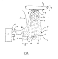
- the figure shows an inventive electrical connection between a signal processing unit and an antenna conductor structure of a glass antenna array of a vehicle.
- an adapter 1 is shown by way of example Construction and function provided.
- a Slice antenna assembly 2 of a vehicle electrically with a signal processing Unit 3, for example, an antenna amplifier, contacted.
- the Slice antenna assembly 2 is schematic for understanding the invention shown and consists of a vehicle window 4, on or in the one Antenna conductor structure 5 is applied or introduced.
- the antenna conductor structure 5 are therefore in a corresponding number of contact surfaces. 6 available.
- it is in the Application of the electrical connection according to the invention not necessarily must act to a vehicle window with the antenna conductor structure, but instead of the vehicle window any flat or spatial structure can act.
- a flexible Line 7 provided, the already described above construction from Covering layer, conductor track or strip conductors and optionally cover layer having.
- a contact area 8 which in its location after the assembly of the Adapter 1 with the position of the contact surface 6 of the glass antenna assembly. 2 corresponds, is the associated contact surface 6 associated track or several tracks of the flexible line 7 exposed and pressed there.
- a corresponding Fasteners such as e.g. Glue point, caulking, screw connection, one or a plurality of preformed elements of the adapter 1 or the like, is provided.
- the other end 11 of the flexible line 7 is in the direction of the signal processing Unit 3 out and there z. B. in the region of an interface 12 electrically and contacted mechanically.
- This connection can be either additional Contact means (such as a connector) or directly done.
- the flexible cable 7 with contacts provided with the contacts on a printed circuit board of the signal processing Unit 3 correspond. That is, the other end 11 of the flexible Line 7 is detachably connected to the signal processing unit 3.
- the adapter 1 consists of a carrier 13, the z. Example, the example in the figure 1 and of an electrically non-conductive material consists.
- this carrier 13 for example, in a plastic injection molding process produced. It has a receiving area 14 in which a Spring element 15, in particular a coil spring, is arranged.
- This Spring element 15 is supported on the carrier 13 and is at its other End provided with a slider 16, thereby forming a pressure element is formed on the contact region 8 of the flexible conduit 7 in the direction of Contact surface 6 acts.
- this slider which is preferably captive on the Carrier 1 is arranged, the contact safety and the balance of Assembly and manufacturing tolerances realized.
- the slider 16 has in preferred Make a rounded shape, where it is conceivable that the area of Slider 16, which faces in the direction of the contact surface 6, elastically deformable is trained.
- pressure element itself from an elastically deformable material to manufacture and in the receiving area 14 of the carrier 13 or at the production of the carrier 13 set in this.
- the carrier 13 of the adapter 1 has a fastening region 17, with the adapter 1 to a part of the vehicle or to the signal processing Unit 3 is mountable.
- the fixation of the adapter 1 takes place e.g. by latching.
- the attachment portion 17 may be so be designed that movement between the part of the vehicle or the signal processing unit 3 is executable for tolerance compensation.
- the attachment portion 17 has two parallel extending and not fully shown legs 18, the form an intermediate slot 19.
- In this slot 19 is a tab 20 insertable, wherein the tab 20 may be part of the vehicle.
- the tab 20 and a part of the signal processing Unit 3 is, such as a tab 20 'of a housing or PCB of the signal processing unit 3.
- the attachment area 17 allows the adapter 1 in its position towards the contact surface 6 of the disc assembly 2 align.
- the attachment area 17 designed so that the adapter with respect to the fixed point one and / or two-dimensional movement (longitudinal and / or transverse movement) can perform. Depending on the size of the tolerances is also a three-dimensional Movement possible, this due to the movement of the pressure element in preferably omitted.
- a single adapter 1 may be present, where it is alternatively conceivable is that with several contact surfaces 6, the associated contact areas 8 in a single adapter 1 are summarized.
- the contact surfaces 6 at such a distance from each other to arrange on the vehicle window 4, as well as the tracks or Contact arms of the flexible conduit 7 are spaced from each other.
- a single flexible conduit 7 is used in accordance with the number of contact surfaces 6, also strip conductors, e.g. has parallel to each other.
- a pressure element 21 is provided, which ensures that the flexible conduit in the contact area 8 around the preferably rounded Head of the slider 16 is guided around and possibly biased.
- This Andrukkelement 21 may be formed tab-shaped and is attached to the carrier 13 or is part of the carrier 13 or is on a part of the vehicle or attached to the signal processing unit 3.
Abstract
Description
Die Erfindung betrifft eine elektrische Verbindung zwischen einer signalverarbeitenden Einheit und einer Antennenstruktur auf oder in einem Fahrzeugteil, insbesondere einer Fahrzeugscheibe, für ein Fahrzeug, gemäß den Merkmalen des Oberbegriffes des Patentanspruchs 1.The invention relates to an electrical connection between a signal processing Unit and an antenna structure on or in a vehicle part, in particular a vehicle window, for a vehicle, according to the features of the preamble of claim 1.
Aus der DE 196 05 999 A1 ist die Kontaktierung einer flächigen Antennenleiterstruktur bekannt. Hierbei wird unterhalb eines Karosserieteiles des Fahrzeuges eine signalverarbeitende Einheit, insbesondere ein Antennenverstärker, über geeignete Befestigungsmittel angeordnet. Das Gehäuse dieser Einheit weist einen Träger (Auslegerarm) auf, an dessen Ende Kontaktierungsmittel vorgesehen sind. Diese Kontaktierungsmittel sind über Verbindungsleitungen, die in oder auf dem starren Träger angeordnet sind, mit der signalverarbeitenden Einheit verbunden. Über die Kontaktierungsmittel erfolgt eine Kontaktierung zu Kontaktflächen einer Antennenleiterstruktur, die sich auf der Fahrzeugscheibe befindet. Über den Träger ist es einerseits möglich, über eine gewisse Distanz die Antennenleiterstruktur mit der signalverarbeitenden Einheit zu verbinden. Aufgrund der Zuordnung des Einbauortes dieser Einheit und der Kontaktierungsfläche der Antennenleiterstruktur sind aber große Toleranzbereiche erforderlich, damit die Kontaktierungsmittel die Kontaktfläche der Antennenleiterstruktur treffen. Ein weiterer Nachteil dieser Konstruktion besteht darin, daß die gesamte signalverarbeitende Einheit mit dem Träger und an dem Träger angeordnete Kontaktierungsmittel vollständig ausgetauscht werden müssen, wenn diese z. B. in einem Crashfall des Fahrzeuges beschädigt worden sind. Damit ist ein hoher Aufwand verbunden, da die signalverarbeitende Einheit im Regelfall zwischen der Karosserie (Fahrzeugdach) und dem Dachhimmel integriert ist und somit nur schwer zugänglich ist. From DE 196 05 999 A1, the contacting of a planar antenna conductor structure known. This is below a body part of the vehicle a signal processing unit, in particular an antenna amplifier, via arranged suitable fastening means. The housing of this unit has a Support (cantilever arm), at the end of contacting means are provided. These contacting means are via connecting lines which are in or on the rigid carrier are arranged, connected to the signal processing unit. About the contacting a contact is made to contact surfaces of a Antenna conductor structure, which is located on the vehicle window. On the Carrier it is possible on the one hand, over a certain distance the antenna conductor structure to connect to the signal processing unit. Due to the assignment the installation location of this unit and the contacting surface of the antenna conductor structure But large tolerance ranges are required so that the contacting meet the contact surface of the antenna conductor structure. Another Disadvantage of this construction is that the entire signal processing Unit with the carrier and arranged on the carrier contacting means have to be completely replaced if this z. B. in a crash of the Vehicle have been damaged. This is a high cost associated with the signal processing unit usually between the body (vehicle roof) and the headliner is integrated and thus difficult to access.
Der Erfindung liegt daher die Aufgabe zugrunde, eine elektrische Verbindung zwischen einer signalverarbeitenden Einheit und einer Antennenleiterstruktur auf oder in einem Fahrzeugteil, insbesondere einer Fahrzeugscheibe, bereitzustellen, die einfach montierbar ist, Toleranzen ausgleicht sowie im Falle einer Beschädigung leicht ersetzbar ist.The invention is therefore based on the object, an electrical connection between a signal processing unit and an antenna conductor structure or in a vehicle part, in particular a vehicle window, to provide which is easy to assemble, compensates tolerances and in case of damage easily replaceable.
Diese Aufgabe ist durch die Merkmale des Patentanspruchs 1 gelöst.This object is solved by the features of patent claim 1.
Erfindungsgemäß ist diese Aufgabe dadurch gelöst, dass die elektrische Verbindung zwischen der signalverarbeitenden Einheit und das Kontaktierungsmittel zusammen als ein flexibles Kontaktelement (flexible Leitung, flexibles Band bzw. sogenanntes Kaptonband, flexibler Leitungsträger)- im folgenden flexible Leitung- ausgebildet sind. Dies hat den Vorteil, dass eine Verbindung, insbesondere eine Steckverbindung, zwischen dem Kontaktierungsmittel und der elektrischen Zuleitung zu der signalverarbeitenden Einheit entfallen kann, so dass sich hohe Übergangswiderstände oder Kontaktschwierigkeiten nicht negativ auswirken können. Außerdem bildet der Träger mit dem Kontaktierungsmittel, bei dem es sich beispielsweise um zumindest eine freiwillige Leiterbahn der flexiblen Leitung handelt, eine vormontierbare Einheit, die je nach Einbausituation an einem beliebigen Teil des Fahrzeuges montiert werden kann. Die flexible Leitung hat darüber hinaus den Vorteil, dass sie auf Grund ihrer extremen flachen Bauweise sehr wenig Platz beansprucht und damit innerhalb des Fahrzeuges, zum Beispiel unter einem Dachhimmel, problemlos verlegt werden kann. Ebenso ist ein Toleranzausgleich möglich, da die flexible Leitung einen großen Spielraum bei der Verlegung gestattet. Weiterhin hat die flexible Leitung noch den Vorteil, dass sie bis zur signalverarbeitenden Einheit, die in der Nähe des Adapters oder auch weit davon angeordnet sein kann, beliebig verlegt werden kann. Dies kann beispielsweise auch durch Falten der flexiblen Leitung erfolgen.According to the invention, this object is achieved in that the electrical Connection between the signal processing unit and the contacting means together as a flexible contact element (flexible cable, flexible band or so-called kapton tape, flexible conductor carrier) - in the following flexible Line are trained. This has the advantage of having a connection, in particular a plug connection, between the contacting means and the electrical Supply line to the signal processing unit can be omitted, so that high contact resistances or contact difficulties do not have a negative effect can. In addition, the carrier forms with the contacting agent in which it For example, at least one voluntary track of the flexible line is a pre-assembled unit, which depending on the installation situation at one Any part of the vehicle can be mounted. The flexible line has moreover, the advantage that they are due to their extreme flat design taken up very little space and thus within the vehicle, for example under a headliner, can be laid easily. Likewise is a Tolerance compensation possible, because the flexible line a large margin in the Laying allowed. Furthermore, the flexible cable still has the advantage that they to the signal processing unit, near the adapter or even far can be arranged, can be arbitrarily moved. This can be, for example also done by folding the flexible conduit.
In Weiterbildung der Erfindung wirkt auf den Kontaktbereich der flexiblen Leitung ein Druckelement. Eine flexible Leitung hat den üblichen Aufbau, dass nämlich auf einer Trägerschicht aus einem nicht leitfähigem Material, insbesondere Kunststoff, eine oder mehrere z. B. parallel verlaufende elektrische Leiterbahnen, insbesondere aus Kupfer, aufgebracht sind. Zur Vermeidung von Oxidationen des Kupfers der Leiterbahnen und ebenfalls zur Vermeidung von elektrischen Kurzschlüssen werden die Leiterbahnen und die benachbarten Bereiche der Trägerschicht mit einer Deckschicht, insbesondere ebenfalls aus einem elektrisch nicht leitfähigem Material und in besonders bevorzugter Weise aus dem gleichen Material wie die Trägerschicht, geschützt. Zur Kontaktierung mit der Antennenleiterstruktur, insbesondere mit einer dort vorgesehenen Kontaktfläche, wird die zumindest eine Leiterbahn der flexiblen Leitung in dem Kontaktbereich freigelegt, d.h., die Deckschicht entfernt, so dass nach der Montage des Adapters dieser Kontaktbereich an der Kontaktfläche der Antennenleiterstruktur zur Anlage kommt. Um die Kontaktsicherheit zu erhöhen und einen Ausgleich von Montage- und Fertigungstoleranzen zu realisieren, wirkt auf diesen Kontaktbereich (und gegebenenfalls Bereiche darum herum) das Druckelement. Da dieser Druck dauerhaft aufrecht erhalten wird, ist eine sichere Kontaktierung über die Lebensdauer der erfindungsgemäßen elektrischen Verbindung sicher gestellt. Außerdem können zwecks Erhöhung der Kontaktsicherheit bei der Kontaktierung einer Kontaktfläche der Antennenleiterstruktur mehrere Leiterbahnen, also zumindest zwei, benutzt werden.In a further development of the invention acts on the contact region of the flexible conduit a pressure element. A flexible line has the usual structure, that is up a carrier layer of a non-conductive material, in particular plastic, one or more z. B. parallel electrical conductor tracks, in particular made of copper, are applied. To avoid oxidation of the copper the tracks and also to avoid electrical short circuits become the conductor tracks and the adjacent areas of the carrier layer with a cover layer, in particular also made of an electrically non-conductive Material and most preferably of the same material as the Carrier layer, protected. For contacting with the antenna conductor structure, in particular with a contact surface provided there, the at least one Conductor of the flexible line exposed in the contact area, that is, the Cover layer removed, so that after mounting the adapter of this contact area comes to rest at the contact surface of the antenna conductor structure. To the Increasing contact reliability and balancing assembly and manufacturing tolerances to realize acts on this contact area (and if necessary Areas around it) the pressure element. Because this pressure is permanent is maintained, is a safe contact over the life of the provided electrical connection according to the invention. In addition, you can in order to increase the contact reliability when contacting a contact surface the antenna conductor structure multiple tracks, so at least two used become.
In Weiterbildung der Erfindung ist das eine Ende der flexiblen Leitung an dem Adapter festgelegt. Daher kann die flexible Leitung nach der Montage des Adapters ohne weiteres in Richtung der signalverarbeitenden Einheit verlegt werden. Alternativ dazu ist es auch denkbar, ein Ende der flexiblen Leitung an der Scheibenantennenanordnung festzulegen.In a further development of the invention, this is an end of the flexible conduit to the Adapters set. Therefore, the flexible pipe after assembly of the Adapters readily laid in the direction of the signal processing unit become. Alternatively, it is also conceivable, an end of the flexible line to the Specify pane antenna arrangement.
In Weiterbildung der Erfindung wirkt im Bereich des Adapters ein Andruckelement auf die flexible Leitung. Dieses Andruckelement bewirkt, dass die flexible Leitung in dem Kontaktbereich in der erforderlichen Form um das Druckelement herumgeführt ist.In a further development of the invention, a pressure element acts in the region of the adapter on the flexible line. This pressure element causes the flexible line in the contact area in the required form led around the pressure element is.
In Weiterbildung der Erfindung ist das andere Ende der flexiblen Leitung mit der signalverarbeitenden Einheit verbunden oder mit einer Schnittstelle der signalverarbeitenden Einheit verbindbar. Die direkte Verbindung, beispielsweise dadurch realisiert, dass zumindest eine elektrische Leiterbahn der flexiblen Leitung mit mindestens einer Leiterbahn oder über ein Kontaktmittel mit mindestens einer Leiterbahn einer Leiterplatte der signalverarbeitenden Einheit unlösbar, z.B. durch Verlöten, verbunden ist, hat den Vorteil, dass Übergangswiderstände und Kontaktprobleme vermieden werden. Somit lässt sich die signalverarbeitende Einheit, die über die flexible Leitung mit dem Adapter zur Kontaktierung verbunden ist, als vormontierbares und prüfbares System herstellen. Alternativ dazu ist es denkbar, dass am anderen Ende der flexiblen Leitung eine Steckverbindung vorgesehen ist, über die der Adapter elektrisch und mechanisch mit der korrespondierenden Steckverbindung (Schnittstelle) an der signalverarbeitenden Einheit verbunden wird.In development of the invention, the other end of the flexible conduit with the signal processing unit connected or with an interface of the signal processing Unit connectable. The direct connection, for example by doing so realized that at least one electrical trace of the flexible line with at least one conductor track or via a contact means with at least one Conductor of a circuit board of the signal processing unit insoluble, e.g. by Soldering, connected, has the advantage that contact resistance and Contact problems are avoided. Thus, the signal processing can be Unit connected via the flexible cable to the adapter for contacting is to create as a pre-assembled and testable system. Alternatively, it is It is conceivable that at the other end of the flexible line a plug connection is provided, via which the adapter electrically and mechanically with the corresponding Plug connection (interface) to the signal processing Unit is connected.
In einer weiteren Ausgestaltung der erfindungsgemäßen Kontaktierung stellt die flexible Leitung einen Teil des Schaltungsträgers der signalverarbeitenden Einheit dar.In a further embodiment of the contacting according to the invention provides flexible line a part of the circuit carrier of the signal processing unit represents.
In Weiterbildung der Erfindung weist der Adapter einen Befestigungsbereich auf, mit dem er an einem Teil des Fahrzeuges oder an der signalverarbeitenden Einheit montierbar ist, wobei in besonders vorteilhafter Weise der Befestigungsbereich derart gestaltet ist, dass eine Bewegung zwischen dem Teil des Fahrzeuges oder der signalverarbeitenden Einheit zwecks Toleranzausgleich ausführbar ist. An dieser Stelle sei noch einmal darauf hingewiesen, dass auf Grund von Fertigungs- und Montagetoleranzen nicht immer eine genaue Positionierung des Adapters für die Kontaktierung mit der Kontaktfläche der Antennenleiterstruktur vorgegeben werden kann. Daher ist es erforderlich, über den erfindungsgemäßen Adapter einen Toleranzausgleich bei gleichzeitiger elektrischer Kontaktsicherheit zu gewährleisten. Zu diesem Zweck wird erfindungsgemäß die Befestigung des Adapters an dem Teil des Fahrzeuges oder auch an der signalverarbeitenden Einheit derart gestaltet, dass eine Relativbewegung des Adapters in Bezug auf den starren Befestigungspunkt gegeben ist. Denn der starre Befestigungspunkt und die Kontaktfläche liegen nach der Montage fest, so dass mittels des Adapters ein Toleranzausgleich bei gleichzeitiger Kontaktierung nach der Montage des Adapters gegeben ist.In a further development of the invention, the adapter has a mounting area, with him on a part of the vehicle or on the signal processing Unit is mounted, and in a particularly advantageous manner, the attachment area designed such that a movement between the part of the vehicle or the signal processing unit is executable for tolerance compensation. At this point, it should again be noted that due to Manufacturing and assembly tolerances are not always accurate positioning of the Adapters for contacting with the contact surface of the antenna conductor structure can be specified. Therefore, it is necessary over the invention Adapter tolerance compensation with simultaneous electrical contact safety to ensure. For this purpose, the attachment of the invention Adapters on the part of the vehicle or at the signal processing Unit designed such that a relative movement of the adapter with respect to given the rigid attachment point. Because the rigid attachment point and the contact surface are fixed after assembly, so that by means of the adapter a tolerance compensation while contacting after assembly of the Adapters is given.
Ein Ausführungsbeispiel der erfindungsgemäßen elektrischen Verbindung mit weiteren Ausgestaltungen, auf die die Erfindung jedoch nicht beschränkt ist, ist im Folgenden beschrieben und anhand der Figur erläutert.An embodiment of the inventive electrical connection with However, further embodiments, to which the invention is not limited, is in Described below and explained with reference to the figure.
Die Figur zeigt eine erfindungsgemäße elektrische Verbindung zwischen einer
signalverarbeitenden Einheit und einer Antennenleiterstruktur einer Scheibenantennenanordnung
eines Fahrzeuges. Zur Kontaktierung, auf die im Folgenden
noch eingegangen wird, ist ein Adapter 1 mit einer beispielhaft dargestellten
Konstruktion und Funktion vorgesehen. Über diesen Adapter 1 wird eine
Scheibenantennenanordnung 2 eines Fahrzeuges elektrisch mit einer signalverarbeitenden
Einheit 3, beispielsweise einem Antennenverstärker, kontaktiert. Die
Scheibenantennenanordnung 2 ist schematisch zum Verständnis der Erfindung
dargestellt und besteht aus einer Fahrzeugscheibe 4, auf oder in der eine
Antennenleiterstruktur 5 aufgebracht bzw. eingebracht ist. Um die Antennenleiterstruktur
5, bei der es sich beispielsweise um ein oder mehrere elektrisch leitende
Bahnen handeln kann, mit der signalverarbeitenden Einheit 3 zu kontaktieren, ist
insbesondere am Ende eines jeden elektrischen Leiters der Antennenleiterstruktur
5 eine Kontaktfläche 6 vorgesehen. In Abhängigkeit der Anzahl der Leiterbahnen
der Antennenleiterstruktur 5 sind also in entsprechender Anzahl Kontaktflächen 6
vorhanden. An dieser Stelle sei auch darauf hingewiesen, dass es sich bei der
Anwendung der erfindungsgemäßen elektrischen Verbindung nicht zwangsweise
um eine Fahrzeugscheibe mit der Antennenleiterstruktur handeln muss, sondern
anstelle der Fahrzeugscheibe ein beliebiges flächiges oder räumliches Gebilde
handeln kann.The figure shows an inventive electrical connection between a
signal processing unit and an antenna conductor structure of a glass antenna array
of a vehicle. For contacting, on the following
will be discussed, an adapter 1 is shown by way of example
Construction and function provided. About this adapter 1 is a
Zur elektrischen Kontaktierung und zum Toleranzausgleich ist nun eine flexible
Leitung 7 vorgesehen, die den weiter vorne schon geschilderten Aufbau aus
Deckschicht, Leiterbahn oder Leiterbahnen sowie gegebenenfalls Deckschicht
aufweist. In einem Kontaktbereich 8, der in seiner Lage nach der Montage des
Adapters 1 mit der Lage der Kontaktfläche 6 der Scheibenantennenanordnung 2
korrespondiert, wird die für die zugehörige Kontaktfläche 6 zugehörige Leiterbahn
oder mehrere Leiterbahnen der flexiblen Leitung 7 freigelegt und dort angedrückt.
Zur Lagesicherung der flexiblen Leitung 7 ist dessen eines Ende 9 an dem
Adapter 1 festgelegt, wozu an einem Befestigungspunkt 10 ein entsprechendes
Befestigungsmittel, wie z.B. Klebepunkt, Verstemmung, Verschraubung, ein oder
mehrere vorgeformte Elemente des Adapters 1 oder dergleichen, vorgesehen ist.
Das andere Ende 11 der flexiblen Leitung 7 ist in Richtung der signalverarbeitenden
Einheit 3 geführt und dort z. B. im Bereich einer Schnittstelle 12 elektrisch und
mechanisch kontaktiert. Diese Verbindung kann entweder über zusätzliche
Kontaktmittel (wie einer Steckverbindung) oder auch direkt erfolgen. Bei der
Verbindung über eine Steckverbindung wird die flexible Leitung 7 mit Kontakten
versehen, die mit den Kontakten auf einer Leiterplatte der signalverarbeitenden
Einheit 3 korrespondieren. Das heißt, dass das andere Ende 11 der flexiblen
Leitung 7 lösbar mit der signalverarbeitenden Einheit 3 verbunden ist. Sind die
Leiterbahn (oder die Leiterbahnen) der flexiblen Leitung 7 mit der Leiterplatte der
signalverarbeitenden Einheit 3 direkt, z.B. durch Verlöten, verbunden, handelt es
sich um eine unlösbare Verbindung, so dass der Adapter 1 zusammen mit der
signalverarbeitenden Einheit 3 ein Modul bilden. Dies ist auch dann der Fall, wenn
die flexible Leitung 7 ein Bestandteil des Schaltungsträgers der signalverarbeitenden
Einheit 3 ist, wobei der Schaltungsträger z.B. vollständig flexibel oder starrflexibel
ausgebildet werden kann.For electrical contacting and tolerance compensation is now a
Der Adapter 1 besteht aus einem Träger 13, der z. B. die beispielhaft in der Figur
1 gezeigte Form aufweist und aus einem elektrisch nicht leitfähigen Material
besteht. So wird dieser Träger 13 beispielsweise in einem Kunststoffspritzgussverfahren
hergestellt. Er weist einen Aufnahmebereich 14 auf, in dem ein
Federelement 15, insbesondere eine Spiralfeder, angeordnet ist. Dieses
Federelement 15 stützt sich an dem Träger 13 ab und ist an seinem anderen
Ende mit einem Schieber 16 versehen, so dass dadurch ein Druckelement
gebildet wird, das auf den Kontaktbereich 8 der flexiblen Leitung 7 in Richtung der
Kontaktfläche 6 wirkt. Mit diesem Schieber, der vorzugsweise unverlierbar an dem
Träger 1 angeordnet ist, wird die Kontaktsicherheit und der Ausgleich der
Montage- und Fertigungstoleranzen realisiert. Der Schieber 16 weist in bevorzugter
Weise eine abgerundete Form auf, wobei es denkbar ist, dass der Bereich des
Schiebers 16, der in Richtung der Kontaktfläche 6 weist, elastisch verformbar
ausgebildet ist. Alternativ zu dem Schieber 16 mit dem Federelement 15 ist es
denkbar, dass Druckelement selber aus einem elastisch verformbaren Material
herzustellen und in den Aufnahmebereich 14 des Trägers 13 einzusetzen oder bei
der Herstellung des Trägers 13 in diesem festzulegen.The adapter 1 consists of a
Weiterhin weist der Träger 13 des Adapters 1 einen Befestigungsbereich 17 auf,
mit dem der Adapter 1 an einem Teil des Fahrzeuges oder auch an der signalverarbeitenden
Einheit 3 montierbar ist. Die Fixierung des Adapters 1 erfolgt dabei
z.B. durch Verrastung. Alternativ dazu kann der Befestigungsbereich 17 derart
gestaltet werden, dass eine Bewegung zwischen dem Teil des Fahrzeuges oder
der signalverarbeitenden Einheit 3 zwecks Toleranzausgleich ausführbar ist. Bei
diesem konkreten Ausführungsbeispiel weist der Befestigungsbereich 17 zwei
parallel verlaufende und hier nicht vollständig dargestellte Schenkel 18 auf, die
einen dazwischen liegenden Schlitz 19 bilden. In diesen Schlitz 19 ist eine Lasche
20 einführbar, wobei die Lasche 20 ein Teil des Fahrzeuges sein kann. Alternativ
dazu ist es denkbar, dass die Lasche 20 auch ein Teil der signalverarbeitenden
Einheit 3 ist, so beispielsweise eine Lasche 20' eines Gehäuses oder der
Leiterplatte der signalverarbeitenden Einheit 3. Über diese in beliebiger Form
gestaltete Lasche 20 wird also der Adapter 1 relativ bewegbar zu einem Fahrzeugteil
oder der signalverarbeitenden Einheit 3, die an dem Fahrzeugteil
montierbar ist, festgesetzt, wobei es die gezeigte Ausgestaltung des Befestigungsbereiches
17 erlaubt, den Adapter 1 in seiner Lage hin zu der Kontaktfläche
6 der Scheibenanordnung 2 auszurichten. Allgemein ist dazu der Befestigungsbereich
17 so gestaltet, dass der Adapter in Bezug auf den Fixpunkt eine einund/oder
zweidimensionale Bewegung (Längs- und/oder Querbewegung)
ausführen kann. Je nach Größe der Toleranzen ist auch eine dreidimensionale
Bewegung möglich, wobei diese auf Grund der Bewegung des Druckelementes in
bevorzugter Weise entfallen kann.Furthermore, the
Zur Verdeutlichung der Erfindung sei noch darauf hingewiesen, dass je Kontaktfläche
6 ein einzelner Adapter 1 vorhanden sein kann, wobei es alternativ denkbar
ist, dass bei mehreren Kontaktflächen 6 die zugehörigen Kontaktbereiche 8 in
einem einzigen Adapter 1 zusammengefasst sind. Hier bietet es sich in besonders
vorteilhafter Weise an, die Kontaktflächen 6 in einem solchen Abstand voneinander
auf der Fahrzeugscheibe 4 anzuordnen, wie auch die Leiterbahnen bzw.
Kontaktarme der flexiblen Leitung 7 voneinander beabstandet sind. Je nach
Anzahl der Kontaktflächen 6 wird also eine einzige flexible Leitung 7 verwendet,
die entsprechend der Anzahl der Kontaktflächen 6 auch Leiterbahnen, die z.B.
parallel zueinander verlaufen aufweist.To illustrate the invention should also be noted that per contact surface
6 a single adapter 1 may be present, where it is alternatively conceivable
is that with
Zur Führung der flexiblen Leitung 7 oder deren Kontaktarme ist, in etwa auf der
gegenüberliegenden Seite des Befestigungspunktes 10 des einen Endes 9 der
flexiblen Leitung 7, ein Andruckelement 21 vorgesehen, welches gewährleistet,
dass die flexible Leitung im Kontaktbereich 8 um den vorzugsweise abgerundeten
Kopf des Schiebers 16 herumgeführt und ggf. vorgespannt wird. Dieses Andrukkelement
21 kann laschenförmig ausgebildet sein und ist am Träger 13 befestigt
oder stellt einen Teil des Trägers 13 dar oder ist an einem Teil des Fahrzeugs
oder an der signalverarbeitenden Einheit 3 befestigt. To guide the
- 1.1.
- Adapteradapter
- 2.Second
- ScheibenantennenanordnungGlass antenna device
- 3.Third
- Signalverarbeitende EinheitSignal processing unit
- 4.4th
- Fahrzeugscheibevehicle window
- 5.5th
- AntennenleiterstrukturAntenna conductor structure
- 6.6th
- Kontaktflächecontact area
- 7.7th
- Flexible LeitungFlexible line
- 8.8th.
- Kontaktbereichcontact area
- 9.9th
- Ein Ende der flexiblen LeitungAn end of the flexible pipe
- 10.10th
- Befestigungspunktattachment point
- 11.11th
- Anderes Ende der flexiblen LeitungDifferent end of flexible lead
- 12.12th
- Schnittstelleinterface
- 13.13th
- Trägercarrier
- 14.14th
- Aufnahmebereichreception area
- 15.15th
- Federelementspring element
- 16.16th
- Schieberpusher
- 17.17th
- Befestigungsbereichfastening area
- 18.18th
- Schenkelleg
- 19.19th
- Schlitzslot
- 20.20th
- Lascheflap
- 21 .21.
- Andruckelementpresser
Claims (14)
Applications Claiming Priority (4)
| Application Number | Priority Date | Filing Date | Title |
|---|---|---|---|
| DE10347957 | 2003-10-10 | ||
| DE10347957 | 2003-10-10 | ||
| DE102004025619 | 2004-05-25 | ||
| DE102004025619A DE102004025619A1 (en) | 2003-10-10 | 2004-05-25 | Contacting an antenna structure with a flexible cable |
Publications (1)
| Publication Number | Publication Date |
|---|---|
| EP1523060A1 true EP1523060A1 (en) | 2005-04-13 |
Family
ID=34315017
Family Applications (1)
| Application Number | Title | Priority Date | Filing Date |
|---|---|---|---|
| EP04022495A Withdrawn EP1523060A1 (en) | 2003-10-10 | 2004-09-22 | Connection of a window pane antenna with a flexible flexible conduit |
Country Status (2)
| Country | Link |
|---|---|
| US (1) | US7088296B2 (en) |
| EP (1) | EP1523060A1 (en) |
Cited By (1)
| Publication number | Priority date | Publication date | Assignee | Title |
|---|---|---|---|---|
| WO2009074197A2 (en) * | 2007-12-11 | 2009-06-18 | Ccs Technology, Inc. | Electrical plug connector |
Families Citing this family (2)
| Publication number | Priority date | Publication date | Assignee | Title |
|---|---|---|---|---|
| GB201020014D0 (en) | 2010-11-25 | 2011-01-12 | Pilkington Group Ltd | Vehicle design for soldered glazing connector |
| DE102021110345A1 (en) * | 2021-04-22 | 2022-10-27 | Hirschmann Car Communication Gmbh | Method for determining a connection status between an antenna amplifier and an antenna structure, diagnostic module and antenna amplifier |
Citations (6)
| Publication number | Priority date | Publication date | Assignee | Title |
|---|---|---|---|---|
| US4707591A (en) * | 1985-06-28 | 1987-11-17 | General Motors Corporation | Electrically heatable automobile window power-supply connector assembly |
| US5521606A (en) * | 1992-02-05 | 1996-05-28 | Nippon Sheet Glass Co., Ltd. | Window glass antenna for motor vehicles |
| EP1109248A1 (en) * | 1999-12-01 | 2001-06-20 | Volkswagen Aktiengesellschaft | Vehicle antenna arrangement |
| DE10030066A1 (en) * | 2000-06-19 | 2001-12-20 | Guardian Automotive Europ S A | Connector unit for joining electrically conductive elements of a glass sheet comprises at least one contact region on the surface of the glass sheet, and at least one connector element with insulation material |
| DE20210286U1 (en) * | 2002-07-03 | 2002-12-12 | Fuba Automotive Gmbh | Adapter for HF connections |
| US20030176095A1 (en) * | 2000-06-09 | 2003-09-18 | Hirschmann Austria Gmbh | Device for connecting electrical conductors |
Family Cites Families (6)
| Publication number | Priority date | Publication date | Assignee | Title |
|---|---|---|---|---|
| BE748846A (en) | 1969-04-24 | 1970-09-16 | Lindal Skuli W | PRE-STRESSED WOODEN BEAM, HORIZONTAL LAYERS, WOODEN AND METAL LAYERS, AND METHOD FOR ITS |
| US3945014A (en) * | 1970-03-21 | 1976-03-16 | Saint-Gobain Industries | Windshield antenna with coupling network in the leadin |
| DE19605999C2 (en) * | 1996-02-17 | 1999-10-14 | Daimler Chrysler Ag | Contacting a flat antenna conductor structure |
| US6638075B2 (en) * | 2002-02-27 | 2003-10-28 | James R. Spaulding | Electrical connection to windshield/backglass |
| JP3910490B2 (en) * | 2002-05-29 | 2007-04-25 | 小島プレス工業株式会社 | Vehicle antenna structure |
| DE10258101B3 (en) * | 2002-12-11 | 2004-04-08 | Hirschmann Electronics Gmbh & Co. Kg | Automobile antenna device has contact spring providing electrical connection between antenna structure and antenna amplifier n opposite sides of insulating carrier plate |
-
2004
- 2004-09-22 EP EP04022495A patent/EP1523060A1/en not_active Withdrawn
- 2004-10-07 US US10/960,428 patent/US7088296B2/en not_active Expired - Fee Related
Patent Citations (6)
| Publication number | Priority date | Publication date | Assignee | Title |
|---|---|---|---|---|
| US4707591A (en) * | 1985-06-28 | 1987-11-17 | General Motors Corporation | Electrically heatable automobile window power-supply connector assembly |
| US5521606A (en) * | 1992-02-05 | 1996-05-28 | Nippon Sheet Glass Co., Ltd. | Window glass antenna for motor vehicles |
| EP1109248A1 (en) * | 1999-12-01 | 2001-06-20 | Volkswagen Aktiengesellschaft | Vehicle antenna arrangement |
| US20030176095A1 (en) * | 2000-06-09 | 2003-09-18 | Hirschmann Austria Gmbh | Device for connecting electrical conductors |
| DE10030066A1 (en) * | 2000-06-19 | 2001-12-20 | Guardian Automotive Europ S A | Connector unit for joining electrically conductive elements of a glass sheet comprises at least one contact region on the surface of the glass sheet, and at least one connector element with insulation material |
| DE20210286U1 (en) * | 2002-07-03 | 2002-12-12 | Fuba Automotive Gmbh | Adapter for HF connections |
Cited By (2)
| Publication number | Priority date | Publication date | Assignee | Title |
|---|---|---|---|---|
| WO2009074197A2 (en) * | 2007-12-11 | 2009-06-18 | Ccs Technology, Inc. | Electrical plug connector |
| WO2009074197A3 (en) * | 2007-12-11 | 2009-10-01 | Ccs Technology, Inc. | Electrical plug connector |
Also Published As
| Publication number | Publication date |
|---|---|
| US7088296B2 (en) | 2006-08-08 |
| US20050099346A1 (en) | 2005-05-12 |
Similar Documents
| Publication | Publication Date | Title |
|---|---|---|
| DE4413043C2 (en) | Coupling device | |
| EP1854168B1 (en) | Film antenna for a motor vehicle | |
| DE102004025627A1 (en) | Solar module with connection element | |
| EP2380241B1 (en) | Contact-making plug and contact-making plug connection | |
| DE102007041892A1 (en) | Electrical switching arrangement with a MID circuit carrier and a connection interface connected thereto | |
| DE112018000463T5 (en) | Circuit connecting device | |
| DE3345701A1 (en) | Electrical switching apparatus having an end connecting plate which supports plug parts | |
| EP1985162B1 (en) | Holder for a flexible circuit board | |
| DE2441665B2 (en) | Automotive electrical wiring system in the form of a flexible printed tape line | |
| EP1523060A1 (en) | Connection of a window pane antenna with a flexible flexible conduit | |
| EP1467431B1 (en) | Adapter for contacting an antenna structure for vehicles | |
| DE102005033593B3 (en) | Contact spring in a support frame of an antenna amplifier of a vehicle | |
| DE102016107898B4 (en) | Lateral PCB connection | |
| DE102006009582B4 (en) | Electronic device of a vehicle, in particular an antenna amplifier or a TV tuner, with a receiving space for a connector | |
| EP1717103B1 (en) | Rearview mirror for a motor vehicle | |
| DE102004025619A1 (en) | Contacting an antenna structure with a flexible cable | |
| DE102013004377A1 (en) | Method for mounting a connector on a circuit board, connector and electrical connection unit, in particular for a motor vehicle | |
| EP1162694B1 (en) | Apparatus for connecting electrical wires | |
| DE7614112U1 (en) | Plug-in device for connecting electrical components with flat pins | |
| WO2006106008A2 (en) | Arrangement of a printed circuit board in a throttle valve actuator | |
| DE10316384A1 (en) | Contact adapter for contacting an antenna structure of a vehicle | |
| DE3144535A1 (en) | Display device having a liquid crystal display | |
| DE102011079377A1 (en) | Plug module, in particular for window lift drives, and method for its production | |
| DE112020003149T5 (en) | CONNECTOR ASSEMBLY FOR ELECTRICALLY CONNECTING AN ELECTRICAL DEVICE WITH ELECTRICAL CONNECTING MEANS, COMPONENT WITH SUCH CONNECTOR ASSEMBLY AND METHOD FOR MANUFACTURING SUCH COMPONENT | |
| DE102008060733B4 (en) | Connector device |
Legal Events
| Date | Code | Title | Description |
|---|---|---|---|
| PUAI | Public reference made under article 153(3) epc to a published international application that has entered the european phase |
Free format text: ORIGINAL CODE: 0009012 |
|
| AK | Designated contracting states |
Kind code of ref document: A1 Designated state(s): AT BE BG CH CY CZ DE DK EE ES FI FR GB GR HU IE IT LI LU MC NL PL PT RO SE SI SK TR |
|
| AX | Request for extension of the european patent |
Extension state: AL HR LT LV MK |
|
| AKX | Designation fees paid | ||
| STAA | Information on the status of an ep patent application or granted ep patent |
Free format text: STATUS: THE APPLICATION IS DEEMED TO BE WITHDRAWN |
|
| 18D | Application deemed to be withdrawn |
Effective date: 20051014 |
|
| REG | Reference to a national code |
Ref country code: DE Ref legal event code: 8566 |