EP1525859B1 - Self-expanding stent and stent delivery system for treatment of vascular disease - Google Patents
Self-expanding stent and stent delivery system for treatment of vascular disease Download PDFInfo
- Publication number
- EP1525859B1 EP1525859B1 EP04256536A EP04256536A EP1525859B1 EP 1525859 B1 EP1525859 B1 EP 1525859B1 EP 04256536 A EP04256536 A EP 04256536A EP 04256536 A EP04256536 A EP 04256536A EP 1525859 B1 EP1525859 B1 EP 1525859B1
- Authority
- EP
- European Patent Office
- Prior art keywords
- stent
- self
- retaining ring
- expanding
- expanding stent
- Prior art date
- Legal status (The legal status is an assumption and is not a legal conclusion. Google has not performed a legal analysis and makes no representation as to the accuracy of the status listed.)
- Expired - Fee Related
Links
Images


Classifications
-
- A—HUMAN NECESSITIES
- A61—MEDICAL OR VETERINARY SCIENCE; HYGIENE
- A61F—FILTERS IMPLANTABLE INTO BLOOD VESSELS; PROSTHESES; DEVICES PROVIDING PATENCY TO, OR PREVENTING COLLAPSING OF, TUBULAR STRUCTURES OF THE BODY, e.g. STENTS; ORTHOPAEDIC, NURSING OR CONTRACEPTIVE DEVICES; FOMENTATION; TREATMENT OR PROTECTION OF EYES OR EARS; BANDAGES, DRESSINGS OR ABSORBENT PADS; FIRST-AID KITS
- A61F2/00—Filters implantable into blood vessels; Prostheses, i.e. artificial substitutes or replacements for parts of the body; Appliances for connecting them with the body; Devices providing patency to, or preventing collapsing of, tubular structures of the body, e.g. stents
- A61F2/95—Instruments specially adapted for placement or removal of stents or stent-grafts
- A61F2/962—Instruments specially adapted for placement or removal of stents or stent-grafts having an outer sleeve
- A61F2/966—Instruments specially adapted for placement or removal of stents or stent-grafts having an outer sleeve with relative longitudinal movement between outer sleeve and prosthesis, e.g. using a push rod
-
- A—HUMAN NECESSITIES
- A61—MEDICAL OR VETERINARY SCIENCE; HYGIENE
- A61F—FILTERS IMPLANTABLE INTO BLOOD VESSELS; PROSTHESES; DEVICES PROVIDING PATENCY TO, OR PREVENTING COLLAPSING OF, TUBULAR STRUCTURES OF THE BODY, e.g. STENTS; ORTHOPAEDIC, NURSING OR CONTRACEPTIVE DEVICES; FOMENTATION; TREATMENT OR PROTECTION OF EYES OR EARS; BANDAGES, DRESSINGS OR ABSORBENT PADS; FIRST-AID KITS
- A61F2/00—Filters implantable into blood vessels; Prostheses, i.e. artificial substitutes or replacements for parts of the body; Appliances for connecting them with the body; Devices providing patency to, or preventing collapsing of, tubular structures of the body, e.g. stents
- A61F2/82—Devices providing patency to, or preventing collapsing of, tubular structures of the body, e.g. stents
- A61F2/86—Stents in a form characterised by the wire-like elements; Stents in the form characterised by a net-like or mesh-like structure
- A61F2/90—Stents in a form characterised by the wire-like elements; Stents in the form characterised by a net-like or mesh-like structure characterised by a net-like or mesh-like structure
- A61F2/91—Stents in a form characterised by the wire-like elements; Stents in the form characterised by a net-like or mesh-like structure characterised by a net-like or mesh-like structure made from perforated sheet material or tubes, e.g. perforated by laser cuts or etched holes
- A61F2/915—Stents in a form characterised by the wire-like elements; Stents in the form characterised by a net-like or mesh-like structure characterised by a net-like or mesh-like structure made from perforated sheet material or tubes, e.g. perforated by laser cuts or etched holes with bands having a meander structure, adjacent bands being connected to each other
-
- A—HUMAN NECESSITIES
- A61—MEDICAL OR VETERINARY SCIENCE; HYGIENE
- A61F—FILTERS IMPLANTABLE INTO BLOOD VESSELS; PROSTHESES; DEVICES PROVIDING PATENCY TO, OR PREVENTING COLLAPSING OF, TUBULAR STRUCTURES OF THE BODY, e.g. STENTS; ORTHOPAEDIC, NURSING OR CONTRACEPTIVE DEVICES; FOMENTATION; TREATMENT OR PROTECTION OF EYES OR EARS; BANDAGES, DRESSINGS OR ABSORBENT PADS; FIRST-AID KITS
- A61F2/00—Filters implantable into blood vessels; Prostheses, i.e. artificial substitutes or replacements for parts of the body; Appliances for connecting them with the body; Devices providing patency to, or preventing collapsing of, tubular structures of the body, e.g. stents
- A61F2/82—Devices providing patency to, or preventing collapsing of, tubular structures of the body, e.g. stents
- A61F2/848—Devices providing patency to, or preventing collapsing of, tubular structures of the body, e.g. stents having means for fixation to the vessel wall, e.g. barbs
-
- A—HUMAN NECESSITIES
- A61—MEDICAL OR VETERINARY SCIENCE; HYGIENE
- A61F—FILTERS IMPLANTABLE INTO BLOOD VESSELS; PROSTHESES; DEVICES PROVIDING PATENCY TO, OR PREVENTING COLLAPSING OF, TUBULAR STRUCTURES OF THE BODY, e.g. STENTS; ORTHOPAEDIC, NURSING OR CONTRACEPTIVE DEVICES; FOMENTATION; TREATMENT OR PROTECTION OF EYES OR EARS; BANDAGES, DRESSINGS OR ABSORBENT PADS; FIRST-AID KITS
- A61F2/00—Filters implantable into blood vessels; Prostheses, i.e. artificial substitutes or replacements for parts of the body; Appliances for connecting them with the body; Devices providing patency to, or preventing collapsing of, tubular structures of the body, e.g. stents
- A61F2/82—Devices providing patency to, or preventing collapsing of, tubular structures of the body, e.g. stents
- A61F2/86—Stents in a form characterised by the wire-like elements; Stents in the form characterised by a net-like or mesh-like structure
-
- A—HUMAN NECESSITIES
- A61—MEDICAL OR VETERINARY SCIENCE; HYGIENE
- A61F—FILTERS IMPLANTABLE INTO BLOOD VESSELS; PROSTHESES; DEVICES PROVIDING PATENCY TO, OR PREVENTING COLLAPSING OF, TUBULAR STRUCTURES OF THE BODY, e.g. STENTS; ORTHOPAEDIC, NURSING OR CONTRACEPTIVE DEVICES; FOMENTATION; TREATMENT OR PROTECTION OF EYES OR EARS; BANDAGES, DRESSINGS OR ABSORBENT PADS; FIRST-AID KITS
- A61F2/00—Filters implantable into blood vessels; Prostheses, i.e. artificial substitutes or replacements for parts of the body; Appliances for connecting them with the body; Devices providing patency to, or preventing collapsing of, tubular structures of the body, e.g. stents
- A61F2/95—Instruments specially adapted for placement or removal of stents or stent-grafts
- A61F2/958—Inflatable balloons for placing stents or stent-grafts
-
- A—HUMAN NECESSITIES
- A61—MEDICAL OR VETERINARY SCIENCE; HYGIENE
- A61F—FILTERS IMPLANTABLE INTO BLOOD VESSELS; PROSTHESES; DEVICES PROVIDING PATENCY TO, OR PREVENTING COLLAPSING OF, TUBULAR STRUCTURES OF THE BODY, e.g. STENTS; ORTHOPAEDIC, NURSING OR CONTRACEPTIVE DEVICES; FOMENTATION; TREATMENT OR PROTECTION OF EYES OR EARS; BANDAGES, DRESSINGS OR ABSORBENT PADS; FIRST-AID KITS
- A61F2/00—Filters implantable into blood vessels; Prostheses, i.e. artificial substitutes or replacements for parts of the body; Appliances for connecting them with the body; Devices providing patency to, or preventing collapsing of, tubular structures of the body, e.g. stents
- A61F2/82—Devices providing patency to, or preventing collapsing of, tubular structures of the body, e.g. stents
- A61F2/848—Devices providing patency to, or preventing collapsing of, tubular structures of the body, e.g. stents having means for fixation to the vessel wall, e.g. barbs
- A61F2002/8486—Devices providing patency to, or preventing collapsing of, tubular structures of the body, e.g. stents having means for fixation to the vessel wall, e.g. barbs provided on at least one of the ends
-
- A—HUMAN NECESSITIES
- A61—MEDICAL OR VETERINARY SCIENCE; HYGIENE
- A61F—FILTERS IMPLANTABLE INTO BLOOD VESSELS; PROSTHESES; DEVICES PROVIDING PATENCY TO, OR PREVENTING COLLAPSING OF, TUBULAR STRUCTURES OF THE BODY, e.g. STENTS; ORTHOPAEDIC, NURSING OR CONTRACEPTIVE DEVICES; FOMENTATION; TREATMENT OR PROTECTION OF EYES OR EARS; BANDAGES, DRESSINGS OR ABSORBENT PADS; FIRST-AID KITS
- A61F2/00—Filters implantable into blood vessels; Prostheses, i.e. artificial substitutes or replacements for parts of the body; Appliances for connecting them with the body; Devices providing patency to, or preventing collapsing of, tubular structures of the body, e.g. stents
- A61F2/82—Devices providing patency to, or preventing collapsing of, tubular structures of the body, e.g. stents
- A61F2/86—Stents in a form characterised by the wire-like elements; Stents in the form characterised by a net-like or mesh-like structure
- A61F2/90—Stents in a form characterised by the wire-like elements; Stents in the form characterised by a net-like or mesh-like structure characterised by a net-like or mesh-like structure
- A61F2/91—Stents in a form characterised by the wire-like elements; Stents in the form characterised by a net-like or mesh-like structure characterised by a net-like or mesh-like structure made from perforated sheet material or tubes, e.g. perforated by laser cuts or etched holes
- A61F2/915—Stents in a form characterised by the wire-like elements; Stents in the form characterised by a net-like or mesh-like structure characterised by a net-like or mesh-like structure made from perforated sheet material or tubes, e.g. perforated by laser cuts or etched holes with bands having a meander structure, adjacent bands being connected to each other
- A61F2002/91533—Stents in a form characterised by the wire-like elements; Stents in the form characterised by a net-like or mesh-like structure characterised by a net-like or mesh-like structure made from perforated sheet material or tubes, e.g. perforated by laser cuts or etched holes with bands having a meander structure, adjacent bands being connected to each other characterised by the phase between adjacent bands
-
- A—HUMAN NECESSITIES
- A61—MEDICAL OR VETERINARY SCIENCE; HYGIENE
- A61F—FILTERS IMPLANTABLE INTO BLOOD VESSELS; PROSTHESES; DEVICES PROVIDING PATENCY TO, OR PREVENTING COLLAPSING OF, TUBULAR STRUCTURES OF THE BODY, e.g. STENTS; ORTHOPAEDIC, NURSING OR CONTRACEPTIVE DEVICES; FOMENTATION; TREATMENT OR PROTECTION OF EYES OR EARS; BANDAGES, DRESSINGS OR ABSORBENT PADS; FIRST-AID KITS
- A61F2/00—Filters implantable into blood vessels; Prostheses, i.e. artificial substitutes or replacements for parts of the body; Appliances for connecting them with the body; Devices providing patency to, or preventing collapsing of, tubular structures of the body, e.g. stents
- A61F2/82—Devices providing patency to, or preventing collapsing of, tubular structures of the body, e.g. stents
- A61F2/86—Stents in a form characterised by the wire-like elements; Stents in the form characterised by a net-like or mesh-like structure
- A61F2/90—Stents in a form characterised by the wire-like elements; Stents in the form characterised by a net-like or mesh-like structure characterised by a net-like or mesh-like structure
- A61F2/91—Stents in a form characterised by the wire-like elements; Stents in the form characterised by a net-like or mesh-like structure characterised by a net-like or mesh-like structure made from perforated sheet material or tubes, e.g. perforated by laser cuts or etched holes
- A61F2/915—Stents in a form characterised by the wire-like elements; Stents in the form characterised by a net-like or mesh-like structure characterised by a net-like or mesh-like structure made from perforated sheet material or tubes, e.g. perforated by laser cuts or etched holes with bands having a meander structure, adjacent bands being connected to each other
- A61F2002/9155—Adjacent bands being connected to each other
-
- A—HUMAN NECESSITIES
- A61—MEDICAL OR VETERINARY SCIENCE; HYGIENE
- A61F—FILTERS IMPLANTABLE INTO BLOOD VESSELS; PROSTHESES; DEVICES PROVIDING PATENCY TO, OR PREVENTING COLLAPSING OF, TUBULAR STRUCTURES OF THE BODY, e.g. STENTS; ORTHOPAEDIC, NURSING OR CONTRACEPTIVE DEVICES; FOMENTATION; TREATMENT OR PROTECTION OF EYES OR EARS; BANDAGES, DRESSINGS OR ABSORBENT PADS; FIRST-AID KITS
- A61F2/00—Filters implantable into blood vessels; Prostheses, i.e. artificial substitutes or replacements for parts of the body; Appliances for connecting them with the body; Devices providing patency to, or preventing collapsing of, tubular structures of the body, e.g. stents
- A61F2/95—Instruments specially adapted for placement or removal of stents or stent-grafts
- A61F2002/9505—Instruments specially adapted for placement or removal of stents or stent-grafts having retaining means other than an outer sleeve, e.g. male-female connector between stent and instrument
- A61F2002/9511—Instruments specially adapted for placement or removal of stents or stent-grafts having retaining means other than an outer sleeve, e.g. male-female connector between stent and instrument the retaining means being filaments or wires
-
- A—HUMAN NECESSITIES
- A61—MEDICAL OR VETERINARY SCIENCE; HYGIENE
- A61F—FILTERS IMPLANTABLE INTO BLOOD VESSELS; PROSTHESES; DEVICES PROVIDING PATENCY TO, OR PREVENTING COLLAPSING OF, TUBULAR STRUCTURES OF THE BODY, e.g. STENTS; ORTHOPAEDIC, NURSING OR CONTRACEPTIVE DEVICES; FOMENTATION; TREATMENT OR PROTECTION OF EYES OR EARS; BANDAGES, DRESSINGS OR ABSORBENT PADS; FIRST-AID KITS
- A61F2/00—Filters implantable into blood vessels; Prostheses, i.e. artificial substitutes or replacements for parts of the body; Appliances for connecting them with the body; Devices providing patency to, or preventing collapsing of, tubular structures of the body, e.g. stents
- A61F2/95—Instruments specially adapted for placement or removal of stents or stent-grafts
- A61F2/962—Instruments specially adapted for placement or removal of stents or stent-grafts having an outer sleeve
- A61F2/966—Instruments specially adapted for placement or removal of stents or stent-grafts having an outer sleeve with relative longitudinal movement between outer sleeve and prosthesis, e.g. using a push rod
- A61F2002/9665—Instruments specially adapted for placement or removal of stents or stent-grafts having an outer sleeve with relative longitudinal movement between outer sleeve and prosthesis, e.g. using a push rod with additional retaining means
Definitions
- This invention relates to intravascular stents and stent delivery systems for treating a stenosis or for covering an aneurysm within a blood vessel. More particularly, this invention relates to a very small, self-expanding stent which may be used for percutaneous transluminal angioplasty of occluded blood vessels or for providing a cover for an aneurysm within the brain of a patient.
- vascular diseases such as blood vessels that are clogged or narrowed by a lesion or stenosis.
- the objective of this procedure is to increase the inner diameter of the partially occluded blood vessel lumen.
- stents short flexible cylinders or scaffolds, referred to as stents, are often placed into the blood vessel at the site of the stenosis.
- Stents are typically made of metal or polymers and are widely used for reinforcing diseased blood vessels. Some stents are expanded to their proper size using a balloon catheter. Such stents are referred to as ''balloon expandable stents”. Other stents, referred to as “self-expanding stents”, are designed to automatically expand when released. Both balloon expandable stents and self-expanding stents are generally compressed onto a small diameter catheter and are deployed within a blood vessel.
- 2002/0115942 entitled “Low Profile Emboli Capture Device,” discloses an emboli capture device comprised of a filter and a self-expanding stent.
- the self-expanding stent is attached to the filter in order to open the filter when the emboli capture device is placed within an artery.
- Self-expanding stents have generally been compressed onto the outer circumference of a delivery catheter and are then held in the compressed state by an outer catheter which surrounds both the delivery catheter and the stent. As the compressed stent is moved distally out of the distal end of the outer catheter, the stent begins expanding and expands until contact is made between the outer surface of the stent and the inner surface of the wall of a vessel.
- One problem with a self-expanding stent of this type is that once the stent has expanded within the vessel, it is very difficult to remove the stent or to reposition the stent to a different location within the vessel.
- the outer catheter may be completely withdrawn permitting the proximal end of the stent to expand into contact with the vessel wall.
- the outer catheter may be moved distally back over the distal end of the stent to cause the distal end of the stent to again become compressed within the outer catheter.
- the stent, contained within the outer catheter may be repositioned to a different location within the vessel and the same procedure may again be followed for positioning the stent at the new location.
- U.S. 2002/151956 A1 discloses a self-expanding stent and stent delivery system having an elongated core member, a self-expanding stent mounted and compressed onto the elongated core member, and an actuable retaining ring disposed around the self-expanding stent.
- the stent delivery system may include an elongated delivery catheter having a lumen extending therethrough. Disposed within the lumen of the delivery catheter may be the elongated core member.
- An actuatable retaining ring member may be placed around the distal end of the self-expanding stent and served to hold the distal end of the stent in its compressed state. Upon actuation, such as by heating, the retaining ring member yields thereby releasing the distal end of the compressed stent with the result that the stent expands into contact with the inside wall of a blood vessel.
- the retaining ring which is disposed about the proximal portion of the self-expanding stent serves to retain the proximal portion of the stent thereby preventing this portion of the stent to be expanded until such time as the retaining ring is actuated.
- the actuatable retaining rings may be formed of a material which when heated yields to thereby become severed in order to permit the compressed, self-expanded stent to expand into contact with the walls of a vessel.
- the stent delivery system may include a heating element positioned in proximity to the actuatable retaining rings and may also include electrical conductors connected to the heating element for, upon being energized, causing the heating element to heat the actuatable retaining rings with the result that the retaining rings become severed to permit the self-expanding stent to expand into contact with the walls of a vessel.
- the actuatable retaining rings may be comprised of a polymeric material, such as a hot melt polymer, and the heating element may take the form of a resistive heating element.
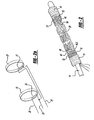
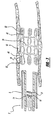
- Figure 1 illustrates an integrated balloon catheter and self-expanding stent including a balloon catheter 2 comprised of an outer catheter 3 having a Luer connector coupling member 5.
- the coupling member 5 includes a delivery port 6 which communicates with a delivery lumen 7, which in turn, extends throughout the length of the balloon catheter 2.
- the coupling member 5 also includes an inflation port 8 used to inflate and expand the balloon 9 disposed about the distal portion 10 of the outer catheter 3.
- the balloon catheter 2 is sufficiently rigid to be pushed distally through a blood vessel, yet flexible enough to traverse the narrow and tortuous blood vessels within a blood vessel, such as a blood vessel within the brain.
- an elongated core wire 14 Slidably disposed within the delivery lumen 7 is an elongated core wire 14. Disposed about the elongated core wire 14 are a proximal cylindrical member 16 and a distal cylindrical member 18, both of which may take the form of a helical coil. A self-expanding sent 20 is mounted on the elongated core wire 14. The proximal and distal cylindrical members 16, 18 are spaced apart to form a gap between the cylindrical member and serve as stop members extending radially outward from the core wire 14 to engage the stent 20 in order to prevent longitudinal movement of the stent relative to the core wire 14.
- a proximal actuatable retaining ring 19 and a distal actuatable retaining ring 21 extend around the proximal and distal portions, respectively, of the stent 20 and serve to restrain the stent in a compressed state.
- the actuatable retaining rings are caused to yield and then sever upon the application of an electrical current which is applied through a power source 23.
- the construction and operation of the actuatable retaining rings 19, 21 are shown in more detail in Figures 2 and 2a .
- Figure 2 illustrates the self-expanding stent 20 mounted on the elongated core wire 14.
- proximal cylindrical member 16 Disposed about the elongated core wire 14 is the proximal cylindrical member 16, which preferably takes the form of a helically wound flexible coil.
- the coil may be formed of metal or of a polymer material.
- a distal cylindrical member 18 is disposed about the elongated core wire 14 and is positioned distally from the proximal cylindrical member 16.
- the distal cylindrical member 18 is spaced apart from the proximal cylindrical member 16 such that the space between the proximal and distal cylindrical members 16, 18 forms a gap 42.
- the distal cylindrical member 18 is also preferably a helically wound flexible coil.
- the self-expanding stent 20 may take on many different patterns or configurations. Examples of such self-expanding stents are disclosed in EP-A-1 266 639 and EP-A-1 266 640 .
- the stent 20 is preferably coated with a bioactive agent, such as heparin or rapamycin, to prevent restenosis within the vessel.
- a bioactive agent such as heparin or rapamycin
- the self-expanding stent 20 is preferably laser cut from a nitinol tube to form a skeletal tubular member.
- the skeletal tubular member has a small diameter and a thin wall which defines a plurality of cells formed by a plurality of interconnected strut members.
- the nitinol is treated so as to exhibit superelastic properties at body temperature.
- the stent 20 includes proximal and distal strut members 44, 46 coupled to the proximal and distal sections 48, 50 of the stent.
- the proximal and distal strut members 44, 46 are cut to form threads on the strut members during the laser-cutting of the stent 20.
- Radiopaque coils are then wound onto the threads of the proximal and distal strut members 44, 46 to form anchor members 52.
- the stent 20 includes eight anchor members 52.
- the anchor members 52 align with and are disposed within the first gap 42 thus coupling the stent to the elongated core wire 14.
- the stent 20 can be moved distally through the delivery lumen 7 of the balloon catheter 2 by moving the core wire 14 distally.
- the self-expanding stent 20 is described in more detail in U.S. Patent Application, Serial No. 10/608,659 (Attorney Docket No. CRD5001 CIP), entitled "Expandable Stent with Radiopaque Markers and Stent Delivery System,” filed on June 27, 2003 and assigned to the same assignee as the present patent application.
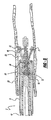
- FIGS 2 and 2a illustrate in more detail the actuatable retaining rings 19, 21 which serve to hold the self-expanding stent in its compressed state.
- the actuatable retaining rings 19, 21 are preferably formed from a filament of a hot melt polymer, such as a polymer marketed by Minnesota Mining and Manufacturing under the trade name Jet Melt, Catalog No. 3783-TC, however, various other biocompatible thermoplastic polymers which exhibit the characteristic of melting, or decreasing yield strength when heat is applied, could be used for the rings.
- the application of heat to the polymer causes the polymer to exhibit the characteristic of yielding and ultimately severing to thereby release the compressed stent.
- the actuatable retaining rings 19,21 serve to clamp the stent onto the elongated core wire 14.
- Resistive heating elements 25, 27 are placed in proximity to the actuatable retaining rings 19, 21, respectively, and the heating elements are coupled through electrical conductors 28, 29, 30, to the power source 23. Accordingly, upon application of electrical current to the resistive heating element 27, the heating element 27 generates heat, which in turn, is applied to the corresponding distal actuatable retaining ring 21 causing this retaining ring to yield and then sever thereby releasing the distal portion of the compressed stent 20. Similarly, when electrical current is applied to the resistive heating element 25, this heating element begins to heat and causes the proximal actuatable retaining ring 19 to yield and sever, and in turn, it releases the proximal portion of the stent 20 to expand from its compressed state.
- Figure 3 shows the balloon catheter 2 inserted within a blood vessel 58 of the brain of a patient.
- the balloon catheter 2 includes an expandable balloon 9 disposed about the distal portion 10 of the elongated outer catheter 3.
- an inflation lumen 60 extends from the inflation port 8 and communicates with the balloon 9.
- a fluid is injected into the inflation lumen 60, through the inflation port 8, to thus expand the balloon 9.
- the operation of the balloon catheter is described in more detail in U.S. Patent No. 6,585,687 .
- the balloon catheter 2 is advanced distally through the blood vessel 58 over a guidewire until it is aligned with a stenosis 62. Then, the guidewire is removed and the elongated core wire 14 is inserted into the delivery lumen 7 of the balloon catheter 2.
- the self-expanding stent 20 is mounted on the elongated core wire 14 such that the anchor members 52 align with and are disposed within the gap 42, between the proximal and distal cylindrical members 16, 18. In this configuration, the stent 20 is engaged to the core wire 14 so that the stent may be moved proximally and distally through the delivery lumen 7 of the balloon catheter 2.
- Figure 4 illustrates the balloon catheter 2 having the expandable balloon 9 fully expanded within the blood vessel 58.
- the balloon 9 is expanded by injecting fluid into the inflation lumen 60 of the balloon catheter.
- the expanded balloon 9 compresses the stenosis 62 and thus increases the luminal diameter of the blood vessel 58.
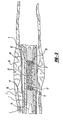
- Figure 5 illustrates the balloon 9 in a deflated configuration and the balloon catheter 2 is moved proximally exposing the distal portion of the stent 20.
- the distal portion of the stent is held in compression by the actuatable retaining ring 21.
- the distal actuatable retaining ring 21 begins to yield and then becomes severed as illustrated.
- the distal portion of the stent 20 expands into contact with the vessel wall.
- the partially expanded stent may be simply withdrawn back into the balloon catheter 2.
- the catheter 2 may then be moved to a new position and the stent may again be moved distally thereby permitting the distal portion of the stent to expand. Since the actuatable retaining ring 21 was severed during the initial placement of the stent, the distal end of the stent will automatically expand into contact with the inside wall of the vessel.
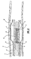
- the balloon catheter 2 is again moved proximally, as illustrated in Figure 6 to also expose the proximal portion of the stent.
- An electrical current may then be applied to the proximal heating element 25 to thereby cause the heating element 25 to begin heating, which in turn, causes the proximal actuatable retaining ring 19 to yield and become severed.
- the proximal portion of the stent 20 expands into contact with the inside wall of the vessel.
- Figure 7 illustrates elongated core wire 14 entirely withdrawn from the stent 20 and into the lumen of the balloon catheter 2.
- the elongated core wire 14 carries with it into the lumen the severed actuatable retaining rings 19, 21.
- Figure 8 illustrates the self-expanding stent 20 expanded into the interior of the vessel so as to serve as a scaffold for maintaining patentcy of the vessel.
- a self-expanding stent is mounted on an elongated core member and is slidably disposed within a balloon catheter.
- the actuatable retaining rings 19, 21 could be formed of a material which would be severed by the process of electrolysis, through a chemical reaction or through another form of electrical activation. Such alternative designs would not depart from the scope of the claims which follow.
Description
- This invention relates to intravascular stents and stent delivery systems for treating a stenosis or for covering an aneurysm within a blood vessel. More particularly, this invention relates to a very small, self-expanding stent which may be used for percutaneous transluminal angioplasty of occluded blood vessels or for providing a cover for an aneurysm within the brain of a patient.
- On a worldwide basis, nearly one million balloon angioplasties are performed annually to treat vascular diseases such as blood vessels that are clogged or narrowed by a lesion or stenosis. The objective of this procedure is to increase the inner diameter of the partially occluded blood vessel lumen. In an effort to prevent restenosis without requiring surgery, short flexible cylinders or scaffolds, referred to as stents, are often placed into the blood vessel at the site of the stenosis.
- Stents are typically made of metal or polymers and are widely used for reinforcing diseased blood vessels. Some stents are expanded to their proper size using a balloon catheter. Such stents are referred to as ''balloon expandable stents". Other stents, referred to as "self-expanding stents", are designed to automatically expand when released. Both balloon expandable stents and self-expanding stents are generally compressed onto a small diameter catheter and are deployed within a blood vessel.
- Several types of balloon catheters have been disclosed in the prior art. One such balloon catheter is disclosed in
U.S. Patent No. 5,843,090 , entitled "Stent Delivery Device," which balloon catheter is used as a stent delivery device.U.S. Patent No. 5,639,274 , entitled "Integrated Catheter System for Balloon Angioplasty and Stent Delivery," discloses an integrated catheter system including a stent deployment catheter and a balloon angioplasty catheter. - Recently, filters mounted on the distal end of guidewires have been proposed for intravascular blood filtration during balloon angioplasty and the delivery of vascular stents. One such filter is disclosed in
U.S. Patent No. 6,168,579 , entitled "Filter Flush System and Methods of Use." This patent discloses a filter flush system for temporary placement of a filter into a blood vessel. The filter system includes a guidewire for carrying an expandable filter which is collapsed to pass through the lumen of a guiding catheter and is then be expanded upstream of a stenosis prior to angioplasty or to the placement of a stent.U.S. Patent Application Publication No. 2002/0115942 , entitled "Low Profile Emboli Capture Device," discloses an emboli capture device comprised of a filter and a self-expanding stent. The self-expanding stent is attached to the filter in order to open the filter when the emboli capture device is placed within an artery. - Self-expanding stents have generally been compressed onto the outer circumference of a delivery catheter and are then held in the compressed state by an outer catheter which surrounds both the delivery catheter and the stent. As the compressed stent is moved distally out of the distal end of the outer catheter, the stent begins expanding and expands until contact is made between the outer surface of the stent and the inner surface of the wall of a vessel. One problem with a self-expanding stent of this type is that once the stent has expanded within the vessel, it is very difficult to remove the stent or to reposition the stent to a different location within the vessel.
- Another form of a self-expanding stent and delivery system is disclosed in
European Patent Application No. 04255121.8 European Patent Application No. 04255205.9
entitled, "Self-Expanding Stent And Stent Delivery System For Treatment Of Vascular Stenosis." Said documents fall under the requirements of Art. 54(3) EPC. Both of these patent applications disclose a stent and stent delivery system in which the distal end of the stent may be expanded into contact with the vessel wall by partially withdrawing the outer catheter from the stent. The proximal end of the stent may be maintained in a compressed form. If it is then determined that the distal end of the stent is properly positioned within the vessel, the outer catheter may be completely withdrawn permitting the proximal end of the stent to expand into contact with the vessel wall. On the other hand, if after the distal end of the stent is expanded into contact with the vessel wall it is determined that the stent should be withdrawn, or repositioned, the outer catheter may be moved distally back over the distal end of the stent to cause the distal end of the stent to again become compressed within the outer catheter. The stent, contained within the outer catheter, may be repositioned to a different location within the vessel and the same procedure may again be followed for positioning the stent at the new location. -
U.S. 2002/151956 A1 discloses a self-expanding stent and stent delivery system having an elongated core member, a self-expanding stent mounted and compressed onto the elongated core member, and an actuable retaining ring disposed around the self-expanding stent. - In accordance with the present invention, there is provided a self-expanding stent and stent delivery system as recited in the claims. The stent delivery system may include an elongated delivery catheter having a lumen extending therethrough. Disposed within the lumen of the delivery catheter may be the elongated core member. An actuatable retaining ring member may be placed around the distal end of the self-expanding stent and served to hold the distal end of the stent in its compressed state. Upon actuation, such as by heating, the retaining ring member yields thereby releasing the distal end of the compressed stent with the result that the stent expands into contact with the inside wall of a blood vessel.
- The retaining ring which is disposed about the proximal portion of the self-expanding stent serves to retain the proximal portion of the stent thereby preventing this portion of the stent to be expanded until such time as the retaining ring is actuated.
- The actuatable retaining rings may be formed of a material which when heated yields to thereby become severed in order to permit the compressed, self-expanded stent to expand into contact with the walls of a vessel.
- The stent delivery system may include a heating element positioned in proximity to the actuatable retaining rings and may also include electrical conductors connected to the heating element for, upon being energized, causing the heating element to heat the actuatable retaining rings with the result that the retaining rings become severed to permit the self-expanding stent to expand into contact with the walls of a vessel.
- The actuatable retaining rings may be comprised of a polymeric material, such as a hot melt polymer, and the heating element may take the form of a resistive heating element.
-
-
Figure 1 is a partially sectional view of an integrated balloon catheter and a self-expanding stent mounted; -
Figure 2 is an oblique view of the self-expanding stent ofFigure 1 mounted on a core wire and held in a compressed state by two actuatable retaining rings; -
Figure 2a is an oblique view of the two actuatable retaining rings and corresponding heating elements; -
Figure 3 is a sectional view of the integrated balloon catheter and self-expanding stent ofFigure 1 within a blood vessel prior to expansion of the balloon and the self-expanding stent; -
Figure 4 is a sectional view of the integrated balloon catheter and self-expanding stent positioned within a blood vessel with the balloon fully expanded; -
Figure 5 is a sectional view of the integrated balloon catheter and self-expanding stent with the balloon deflated and the outer catheter being moved proximally and with the distal actuatable retaining ring severed to release the stent thereby allowing the distal end of the stent to expand within the blood vessel; -
Figure 6 is a sectional view of the proximal actuatable retaining ring severed thereby permitting the self-expanding stent to become fully expanded within the blood vessel; -
Figure 7 is a sectional view of the balloon catheter and elongated core wire withdrawn proximally from the self-expanding stent; and, -
Figure 8 is an elevational view of the self-expanding stent within the blood vessel with the balloon catheter and elongated core wire removed from the blood vessel. -
Figure 1 illustrates an integrated balloon catheter and self-expanding stent including aballoon catheter 2 comprised of anouter catheter 3 having a Luer connector coupling member 5. The coupling member 5 includes a delivery port 6 which communicates with a delivery lumen 7, which in turn, extends throughout the length of theballoon catheter 2. The coupling member 5 also includes aninflation port 8 used to inflate and expand theballoon 9 disposed about thedistal portion 10 of theouter catheter 3. Theballoon catheter 2 is sufficiently rigid to be pushed distally through a blood vessel, yet flexible enough to traverse the narrow and tortuous blood vessels within a blood vessel, such as a blood vessel within the brain. - Slidably disposed within the delivery lumen 7 is an
elongated core wire 14. Disposed about theelongated core wire 14 are a proximalcylindrical member 16 and a distalcylindrical member 18, both of which may take the form of a helical coil. A self-expanding sent 20 is mounted on theelongated core wire 14. The proximal and distalcylindrical members core wire 14 to engage thestent 20 in order to prevent longitudinal movement of the stent relative to thecore wire 14. A proximalactuatable retaining ring 19 and a distalactuatable retaining ring 21 extend around the proximal and distal portions, respectively, of thestent 20 and serve to restrain the stent in a compressed state. The actuatable retaining rings are caused to yield and then sever upon the application of an electrical current which is applied through apower source 23. The construction and operation of the actuatable retaining rings 19, 21 are shown in more detail inFigures 2 and 2a . -
Figure 2 illustrates the self-expandingstent 20 mounted on theelongated core wire 14. Disposed about theelongated core wire 14 is the proximalcylindrical member 16, which preferably takes the form of a helically wound flexible coil. The coil may be formed of metal or of a polymer material. A distalcylindrical member 18 is disposed about theelongated core wire 14 and is positioned distally from the proximalcylindrical member 16. The distalcylindrical member 18 is spaced apart from the proximalcylindrical member 16 such that the space between the proximal and distalcylindrical members gap 42. The distalcylindrical member 18 is also preferably a helically wound flexible coil. - The self-expanding
stent 20 may take on many different patterns or configurations. Examples of such self-expanding stents are disclosed inEP-A-1 266 639 andEP-A-1 266 640 . - The
stent 20 is preferably coated with a bioactive agent, such as heparin or rapamycin, to prevent restenosis within the vessel. Examples of such coatings are disclosed inU.S. Patent Nos. 5,288,711 ;5,516,781 ;5,563,146 and5,646,160 . - The self-expanding
stent 20 is preferably laser cut from a nitinol tube to form a skeletal tubular member. The skeletal tubular member has a small diameter and a thin wall which defines a plurality of cells formed by a plurality of interconnected strut members. The nitinol is treated so as to exhibit superelastic properties at body temperature. Additionally, thestent 20 includes proximal anddistal strut members distal sections distal strut members stent 20. Radiopaque coils are then wound onto the threads of the proximal anddistal strut members anchor members 52. Preferably, thestent 20 includes eightanchor members 52. When the self-expandingstent 20 is mounted on theelongated core wire 14, theanchor members 52 align with and are disposed within thefirst gap 42 thus coupling the stent to theelongated core wire 14. In this configuration, thestent 20 can be moved distally through the delivery lumen 7 of theballoon catheter 2 by moving thecore wire 14 distally. The self-expandingstent 20 is described in more detail inU.S. Patent Application, Serial No. 10/608,659 (Attorney Docket No. CRD5001 CIP), entitled "Expandable Stent with Radiopaque Markers and Stent Delivery System," filed on June 27, 2003 and assigned to the same assignee as the present patent application. - The corresponding
EP-Application 1400 219 falls under Art. 54(3) EPC. -
Figures 2 and 2a illustrate in more detail the actuatable retaining rings 19, 21 which serve to hold the self-expanding stent in its compressed state. The actuatable retaining rings 19, 21 are preferably formed from a filament of a hot melt polymer, such as a polymer marketed by Minnesota Mining and Manufacturing under the trade name Jet Melt, Catalog No. 3783-TC, however, various other biocompatible thermoplastic polymers which exhibit the characteristic of melting, or decreasing yield strength when heat is applied, could be used for the rings. The application of heat to the polymer causes the polymer to exhibit the characteristic of yielding and ultimately severing to thereby release the compressed stent. The actuatable retaining rings 19,21 serve to clamp the stent onto theelongated core wire 14.Resistive heating elements electrical conductors power source 23. Accordingly, upon application of electrical current to theresistive heating element 27, theheating element 27 generates heat, which in turn, is applied to the corresponding distalactuatable retaining ring 21 causing this retaining ring to yield and then sever thereby releasing the distal portion of thecompressed stent 20. Similarly, when electrical current is applied to theresistive heating element 25, this heating element begins to heat and causes the proximalactuatable retaining ring 19 to yield and sever, and in turn, it releases the proximal portion of thestent 20 to expand from its compressed state. -
Figure 3 shows theballoon catheter 2 inserted within ablood vessel 58 of the brain of a patient. Theballoon catheter 2 includes anexpandable balloon 9 disposed about thedistal portion 10 of the elongatedouter catheter 3. In the preferred embodiment of the present invention, aninflation lumen 60 extends from theinflation port 8 and communicates with theballoon 9. To perform an angioplasty of theblood vessel 58, a fluid is injected into theinflation lumen 60, through theinflation port 8, to thus expand theballoon 9. The operation of the balloon catheter is described in more detail inU.S. Patent No. 6,585,687 . - Typically, the
balloon catheter 2 is advanced distally through theblood vessel 58 over a guidewire until it is aligned with astenosis 62. Then, the guidewire is removed and theelongated core wire 14 is inserted into the delivery lumen 7 of theballoon catheter 2. The self-expandingstent 20 is mounted on theelongated core wire 14 such that theanchor members 52 align with and are disposed within thegap 42, between the proximal and distalcylindrical members stent 20 is engaged to thecore wire 14 so that the stent may be moved proximally and distally through the delivery lumen 7 of theballoon catheter 2. -
Figure 4 illustrates theballoon catheter 2 having theexpandable balloon 9 fully expanded within theblood vessel 58. Preferably, theballoon 9 is expanded by injecting fluid into theinflation lumen 60 of the balloon catheter. The expandedballoon 9 compresses thestenosis 62 and thus increases the luminal diameter of theblood vessel 58. -
Figure 5 illustrates theballoon 9 in a deflated configuration and theballoon catheter 2 is moved proximally exposing the distal portion of thestent 20. Initially the distal portion of the stent is held in compression by theactuatable retaining ring 21. When an electrical current is applied to theresistive heating element 27 the distalactuatable retaining ring 21 begins to yield and then becomes severed as illustrated. At this point the distal portion of thestent 20 expands into contact with the vessel wall. After expansion of the distal portion of thestent 20, it is determined that the stent has been improperly positioned, the partially expanded stent may be simply withdrawn back into theballoon catheter 2. Thecatheter 2 may then be moved to a new position and the stent may again be moved distally thereby permitting the distal portion of the stent to expand. Since theactuatable retaining ring 21 was severed during the initial placement of the stent, the distal end of the stent will automatically expand into contact with the inside wall of the vessel. - If on the other hand the distal portion of the stent is properly positioned, the
balloon catheter 2 is again moved proximally, as illustrated inFigure 6 to also expose the proximal portion of the stent. An electrical current may then be applied to theproximal heating element 25 to thereby cause theheating element 25 to begin heating, which in turn, causes the proximalactuatable retaining ring 19 to yield and become severed. Once the retainingring 19 severs, the proximal portion of thestent 20 expands into contact with the inside wall of the vessel. -
Figure 7 illustrates elongatedcore wire 14 entirely withdrawn from thestent 20 and into the lumen of theballoon catheter 2. Theelongated core wire 14 carries with it into the lumen the severed actuatable retaining rings 19, 21. -
Figure 8 illustrates the self-expandingstent 20 expanded into the interior of the vessel so as to serve as a scaffold for maintaining patentcy of the vessel. - A novel system has been disclosed in which a self-expanding stent is mounted on an elongated core member and is slidably disposed within a balloon catheter. Although a preferred embodiment of the present invention has been described, it is to be understood that various modifications may be made by those skilled in the art without departing from the scope of the claims. For example, the actuatable retaining rings 19, 21 could be formed of a material which would be severed by the process of electrolysis, through a chemical reaction or through another form of electrical activation. Such alternative designs would not depart from the scope of the claims which follow.
Claims (8)
- A self-expanding stent (20) and stent delivery system comprising:an elongated core member (14) having proximal and distal portions including a proximal cylindrical member (16) disposed at the distal portion of said elongated core member (14), and a distal cylindrical member (18) disposed at the distal portion of said elongated core member (14) and positioned distally of said proximal cylindrical member (16) and being spaced apart from said proximal cylindrical member (16) to define a gap having a predetermined length;a self-expanding stent (20) having a proximal end which is distal to said proximal cylindrical member (16), said self-expanding stent (20) being comprised of a small diameter skeletal tubular member having an outer cylindrical surface which defines a thin wall, said wall of said skeletal tubular member including a plurality of cells which are formed by a plurality of interconnected strut members (44, 46), and an anchor member (52) placed on one of said plurality of strut members (44, 46) at said proximal end (48) of said stent (20) and having a length less than the length of the gap between the proximal cylindrical member (16) and the distal cylindrical member (18), and said self-expanding stent (20) being mounted and compressed onto said elongated core member (14) such that said anchor member (52) at said proximal end (48) of said stent (20) is interlocked within said gap and between said proximal cylindrical member (16) and said distal cylindrical member (18) to thereby retain said stent (20) on said elongated core member (14); and,a first actuatable retaining ring (19) is disposed around the outer cylindrical surface of said self-expanding stent (20) at said anchor member (52) for retaining said stent (20) onto said elongated core member (14) in a compressed state and said anchor member (52) in said gap, for upon actuation, releasing said self-expanding stent (20) to permit said anchor member (52) to move toward the vessel and the stent (20) to expand against the wall of the vessel and to permit the first actuated retaining ring (19) to be removed from the released stent (20).
- A self-expanding stent and stent delivery system as defined in Claim 1, wherein said self-expanding stent (20) has proximal and distal sections (48, 50), and further comprising a second actuatable retaining ring (21) disposed around the distal portion of the stent (20).
- A self-expanding stent (20) and stent delivery system as defined in Claim 1, wherein said first actuatable retaining ring (19) is formed of a material which when heated permits the compressed self-expanded stent (20) to expand into contact with the wall of a vessel.
- A self-expanding stent (20) and stent delivery system as defined in Claim 3, including a heating element (25) positioned in proximity to said first actuatable retaining ring (19), and electrical conductors (28, 29) connected to said heating element (25) for, upon being energized, causing the temperature of said heating element (25) to increase thereby causing the temperature of the first actuatable retaining ring (19) to increase with the result that the first actuatable retaining ring (19) yields to permit the stent (20) to expand against the wall of a vessel.
- A self-expanding stent (20) and stent delivery system as defined in Claim 3, in which the first actuatable retaining ring (19) is comprised of a polymeric material.
- A self-expanding stent (20) and stent delivery system as defined in Claim 5, in which the first actuatable retaining ring (19) takes the form of a polymeric filament.
- A self-expanding stent (20) and stent delivery system as defined in Claim 5, in which the first actuatable retaining ring (19) is comprised of a filament formed from a hot melt polymer.
- A self-expanding stent (20) and stent delivery system as defined in Claim 4, in which the heating element (25) is an electrical resistive heating element.
Applications Claiming Priority (2)
| Application Number | Priority Date | Filing Date | Title |
|---|---|---|---|
| US10/691,846 US20050049670A1 (en) | 2003-08-29 | 2003-10-23 | Self-expanding stent and stent delivery system for treatment of vascular disease |
| US691846 | 2003-10-23 |
Publications (3)
| Publication Number | Publication Date |
|---|---|
| EP1525859A2 EP1525859A2 (en) | 2005-04-27 |
| EP1525859A3 EP1525859A3 (en) | 2005-06-29 |
| EP1525859B1 true EP1525859B1 (en) | 2008-04-02 |
Family
ID=34394558
Family Applications (1)
| Application Number | Title | Priority Date | Filing Date |
|---|---|---|---|
| EP04256536A Expired - Fee Related EP1525859B1 (en) | 2003-10-23 | 2004-10-22 | Self-expanding stent and stent delivery system for treatment of vascular disease |
Country Status (5)
| Country | Link |
|---|---|
| US (1) | US20050049670A1 (en) |
| EP (1) | EP1525859B1 (en) |
| JP (1) | JP5197909B2 (en) |
| CA (1) | CA2485622C (en) |
| DE (1) | DE602004012816T2 (en) |
Cited By (1)
| Publication number | Priority date | Publication date | Assignee | Title |
|---|---|---|---|---|
| DE102010010483A1 (en) | 2010-02-28 | 2011-09-01 | Björn H. Koslar | Medical implant for connecting two vessels, such as transplant vessel and target vessel, has connecting element that is made of shape memory alloy, where connecting element is formed to roll implant around vessel in spiral manner |
Families Citing this family (82)
| Publication number | Priority date | Publication date | Assignee | Title |
|---|---|---|---|---|
| US8016869B2 (en) * | 2003-03-26 | 2011-09-13 | Biosensors International Group, Ltd. | Guidewire-less stent delivery methods |
| AU2004226464A1 (en) * | 2003-03-26 | 2004-10-14 | Cardiomind, Inc. | Implant delivery technologies |
| US7771463B2 (en) * | 2003-03-26 | 2010-08-10 | Ton Dai T | Twist-down implant delivery technologies |
| US20050209672A1 (en) * | 2004-03-02 | 2005-09-22 | Cardiomind, Inc. | Sliding restraint stent delivery systems |
| US8267985B2 (en) | 2005-05-25 | 2012-09-18 | Tyco Healthcare Group Lp | System and method for delivering and deploying an occluding device within a vessel |
| WO2006127005A1 (en) | 2005-05-25 | 2006-11-30 | Chestnut Medical Technologies, Inc. | System and method for delivering and deploying and occluding device within a vessel |
| WO2006138052A1 (en) * | 2005-06-13 | 2006-12-28 | Exxonmobil Chemical Patents Inc. | Thermoplastic blend compositions |
| US20070100414A1 (en) * | 2005-11-02 | 2007-05-03 | Cardiomind, Inc. | Indirect-release electrolytic implant delivery systems |
| US7655031B2 (en) * | 2006-04-28 | 2010-02-02 | Codman & Shurtleff, Inc. | Stent delivery system with improved retraction member |
| US8545548B2 (en) | 2007-03-30 | 2013-10-01 | DePuy Synthes Products, LLC | Radiopaque markers for implantable stents and methods for manufacturing the same |
| US9149379B2 (en) | 2007-07-16 | 2015-10-06 | Cook Medical Technologies Llc | Delivery device |
| US8092510B2 (en) * | 2007-07-25 | 2012-01-10 | Cook Medical Technologies Llc | Retention wire for self-expanding stent |
| US20090099638A1 (en) * | 2007-10-11 | 2009-04-16 | Med Institute, Inc. | Motorized deployment system |
| US20100256600A1 (en) * | 2009-04-04 | 2010-10-07 | Ferrera David A | Neurovascular otw pta balloon catheter and delivery system |
| CN102006842A (en) * | 2008-03-27 | 2011-04-06 | 纽福克斯神经医疗公司 | Friction-release distal latch implant delivery system and components |
| US9675482B2 (en) | 2008-05-13 | 2017-06-13 | Covidien Lp | Braid implant delivery systems |
| US20090306760A1 (en) * | 2008-06-06 | 2009-12-10 | Bay Street Medical | Prosthesis and delivery system |
| US9402707B2 (en) | 2008-07-22 | 2016-08-02 | Neuravi Limited | Clot capture systems and associated methods |
| US20100069948A1 (en) * | 2008-09-12 | 2010-03-18 | Micrus Endovascular Corporation | Self-expandable aneurysm filling device, system and method of placement |
| US9615949B2 (en) | 2008-12-30 | 2017-04-11 | Cook Medical Technologies Llc | Delivery device |
| JP5284165B2 (en) * | 2009-03-31 | 2013-09-11 | テルモ株式会社 | Biological organ lesion improvement device |
| US8657870B2 (en) * | 2009-06-26 | 2014-02-25 | Biosensors International Group, Ltd. | Implant delivery apparatus and methods with electrolytic release |
| DK2528553T3 (en) * | 2010-01-29 | 2018-01-22 | Cook Medical Technologies Llc | MECHANICAL EXPANDABLE INTRODUCTION AND DILATION SYSTEMS |
| ES2683943T3 (en) | 2010-10-22 | 2018-09-28 | Neuravi Limited | Clot capture and removal system |
| EP3871617A1 (en) | 2011-03-09 | 2021-09-01 | Neuravi Limited | A clot retrieval device for removing occlusive clot from a blood vessel |
| EP2497426B1 (en) * | 2011-03-09 | 2016-12-14 | Aeeg Ab | Device and kit for closure of a body lumen puncture |
| US11259824B2 (en) | 2011-03-09 | 2022-03-01 | Neuravi Limited | Clot retrieval device for removing occlusive clot from a blood vessel |
| US8734500B2 (en) | 2011-09-27 | 2014-05-27 | DePuy Synthes Products, LLC | Distal detachment mechanisms for vascular devices |
| KR101415900B1 (en) | 2012-05-18 | 2014-07-08 | 신경민 | Reiterating type bipolar electrode for high frequency thermotherapy |
| KR101415902B1 (en) * | 2012-05-18 | 2014-07-08 | 신경민 | Catheter provided with cauterization system |
| US9155647B2 (en) * | 2012-07-18 | 2015-10-13 | Covidien Lp | Methods and apparatus for luminal stenting |
| IN2014DE00462A (en) | 2013-03-11 | 2015-06-12 | Depuy Synthes Products Llc | |
| US9308108B2 (en) | 2013-03-13 | 2016-04-12 | Cook Medical Technologies Llc | Controlled release and recapture stent-deployment device |
| US10561509B2 (en) | 2013-03-13 | 2020-02-18 | DePuy Synthes Products, Inc. | Braided stent with expansion ring and method of delivery |
| US9642635B2 (en) | 2013-03-13 | 2017-05-09 | Neuravi Limited | Clot removal device |
| EP2967611B1 (en) | 2013-03-14 | 2019-01-16 | Neuravi Limited | Devices for removal of acute blockages from blood vessels |
| US9433429B2 (en) | 2013-03-14 | 2016-09-06 | Neuravi Limited | Clot retrieval devices |
| JP2016513505A (en) | 2013-03-14 | 2016-05-16 | ニューラヴィ・リミテッド | Clot collection device for removing obstructed clots from blood vessels |
| WO2015061801A2 (en) * | 2013-10-26 | 2015-04-30 | Accumed Radial Systems Llc | System, apparatus, and method for creating a lumen |
| US10285720B2 (en) | 2014-03-11 | 2019-05-14 | Neuravi Limited | Clot retrieval system for removing occlusive clot from a blood vessel |
| WO2015189354A1 (en) | 2014-06-13 | 2015-12-17 | Neuravi Limited | Devices for removal of acute blockages from blood vessels |
| US10792056B2 (en) | 2014-06-13 | 2020-10-06 | Neuravi Limited | Devices and methods for removal of acute blockages from blood vessels |
| US10265086B2 (en) | 2014-06-30 | 2019-04-23 | Neuravi Limited | System for removing a clot from a blood vessel |
| US10206796B2 (en) | 2014-08-27 | 2019-02-19 | DePuy Synthes Products, Inc. | Multi-strand implant with enhanced radiopacity |
| ES2781184T3 (en) | 2014-11-26 | 2020-08-31 | Neuravi Ltd | A clot removal device to remove an occlusive clot from a blood vessel |
| US10617435B2 (en) | 2014-11-26 | 2020-04-14 | Neuravi Limited | Clot retrieval device for removing clot from a blood vessel |
| US11253278B2 (en) | 2014-11-26 | 2022-02-22 | Neuravi Limited | Clot retrieval system for removing occlusive clot from a blood vessel |
| US10478323B2 (en) * | 2014-12-08 | 2019-11-19 | Suntech Co., Ltd. | Biodegradable stent and shape memory expanding method therefor |
| DE102015103240A1 (en) | 2015-03-05 | 2016-09-08 | Phenox Gmbh | implant delivery |
| AU2017312421A1 (en) | 2016-08-17 | 2019-03-07 | Neuravi Limited | A clot retrieval system for removing occlusive clot from a blood vessel |
| US10076428B2 (en) | 2016-08-25 | 2018-09-18 | DePuy Synthes Products, Inc. | Expansion ring for a braided stent |
| BR112019004484A2 (en) | 2016-09-06 | 2019-05-28 | Neuravi Ltd | clot recovery device to remove occlusive clots from a blood vessel |
| US10292851B2 (en) | 2016-09-30 | 2019-05-21 | DePuy Synthes Products, Inc. | Self-expanding device delivery apparatus with dual function bump |
| WO2019118374A1 (en) | 2017-12-12 | 2019-06-20 | Penumbra, Inc. | Vascular cages and methods of making and using the same |
| AU2019204522A1 (en) | 2018-07-30 | 2020-02-13 | DePuy Synthes Products, Inc. | Systems and methods of manufacturing and using an expansion ring |
| US10456280B1 (en) | 2018-08-06 | 2019-10-29 | DePuy Synthes Products, Inc. | Systems and methods of using a braided implant |
| US10278848B1 (en) | 2018-08-06 | 2019-05-07 | DePuy Synthes Products, Inc. | Stent delivery with expansion assisting delivery wire |
| US10842498B2 (en) | 2018-09-13 | 2020-11-24 | Neuravi Limited | Systems and methods of restoring perfusion to a vessel |
| US11406416B2 (en) | 2018-10-02 | 2022-08-09 | Neuravi Limited | Joint assembly for vasculature obstruction capture device |
| US11039944B2 (en) | 2018-12-27 | 2021-06-22 | DePuy Synthes Products, Inc. | Braided stent system with one or more expansion rings |
| EP4000540B1 (en) | 2019-03-04 | 2024-02-14 | Neuravi Limited | Actuated clot retrieval catheter |
| JP2021041169A (en) | 2019-09-11 | 2021-03-18 | ニューラヴィ・リミテッド | Expandable mouth catheter |
| US11712231B2 (en) | 2019-10-29 | 2023-08-01 | Neuravi Limited | Proximal locking assembly design for dual stent mechanical thrombectomy device |
| US11839725B2 (en) | 2019-11-27 | 2023-12-12 | Neuravi Limited | Clot retrieval device with outer sheath and inner catheter |
| US11779364B2 (en) | 2019-11-27 | 2023-10-10 | Neuravi Limited | Actuated expandable mouth thrombectomy catheter |
| US11517340B2 (en) | 2019-12-03 | 2022-12-06 | Neuravi Limited | Stentriever devices for removing an occlusive clot from a vessel and methods thereof |
| US11633198B2 (en) | 2020-03-05 | 2023-04-25 | Neuravi Limited | Catheter proximal joint |
| US11944327B2 (en) | 2020-03-05 | 2024-04-02 | Neuravi Limited | Expandable mouth aspirating clot retrieval catheter |
| US11883043B2 (en) | 2020-03-31 | 2024-01-30 | DePuy Synthes Products, Inc. | Catheter funnel extension |
| US11759217B2 (en) | 2020-04-07 | 2023-09-19 | Neuravi Limited | Catheter tubular support |
| US11730501B2 (en) | 2020-04-17 | 2023-08-22 | Neuravi Limited | Floating clot retrieval device for removing clots from a blood vessel |
| US11871946B2 (en) | 2020-04-17 | 2024-01-16 | Neuravi Limited | Clot retrieval device for removing clot from a blood vessel |
| US11717308B2 (en) | 2020-04-17 | 2023-08-08 | Neuravi Limited | Clot retrieval device for removing heterogeneous clots from a blood vessel |
| US11737771B2 (en) | 2020-06-18 | 2023-08-29 | Neuravi Limited | Dual channel thrombectomy device |
| US11937836B2 (en) | 2020-06-22 | 2024-03-26 | Neuravi Limited | Clot retrieval system with expandable clot engaging framework |
| US11439418B2 (en) | 2020-06-23 | 2022-09-13 | Neuravi Limited | Clot retrieval device for removing clot from a blood vessel |
| US11395669B2 (en) | 2020-06-23 | 2022-07-26 | Neuravi Limited | Clot retrieval device with flexible collapsible frame |
| US11864781B2 (en) | 2020-09-23 | 2024-01-09 | Neuravi Limited | Rotating frame thrombectomy device |
| US11554034B2 (en) * | 2020-10-06 | 2023-01-17 | Venus Medtech (Hangzhou) Inc. | Method and assembly for securing an implantable medical device on a delivery system |
| US11937837B2 (en) | 2020-12-29 | 2024-03-26 | Neuravi Limited | Fibrin rich / soft clot mechanical thrombectomy device |
| US11872354B2 (en) | 2021-02-24 | 2024-01-16 | Neuravi Limited | Flexible catheter shaft frame with seam |
| US11937839B2 (en) | 2021-09-28 | 2024-03-26 | Neuravi Limited | Catheter with electrically actuated expandable mouth |
Family Cites Families (53)
| Publication number | Priority date | Publication date | Assignee | Title |
|---|---|---|---|---|
| US2680465A (en) * | 1950-05-02 | 1954-06-08 | Khalil Seyed | Pneumatic vehicle tire |
| EP0257091B1 (en) * | 1986-02-24 | 1993-07-28 | Robert E. Fischell | An intravascular stent and percutaneous insertion system |
| US4950277A (en) * | 1989-01-23 | 1990-08-21 | Interventional Technologies, Inc. | Atherectomy cutting device with eccentric wire and method |
| US5350398A (en) * | 1991-05-13 | 1994-09-27 | Dusan Pavcnik | Self-expanding filter for percutaneous insertion |
| US5192297A (en) * | 1991-12-31 | 1993-03-09 | Medtronic, Inc. | Apparatus and method for placement and implantation of a stent |
| US5516781A (en) * | 1992-01-09 | 1996-05-14 | American Home Products Corporation | Method of treating restenosis with rapamycin |
| US5201757A (en) * | 1992-04-03 | 1993-04-13 | Schneider (Usa) Inc. | Medial region deployment of radially self-expanding stents |
| US5288711A (en) * | 1992-04-28 | 1994-02-22 | American Home Products Corporation | Method of treating hyperproliferative vascular disease |
| US5306294A (en) * | 1992-08-05 | 1994-04-26 | Ultrasonic Sensing And Monitoring Systems, Inc. | Stent construction of rolled configuration |
| SG85682A1 (en) * | 1993-03-11 | 2002-01-15 | Medinol Ltd | Stent |
| US6165213A (en) * | 1994-02-09 | 2000-12-26 | Boston Scientific Technology, Inc. | System and method for assembling an endoluminal prosthesis |
| US5554181A (en) * | 1994-05-04 | 1996-09-10 | Regents Of The University Of Minnesota | Stent |
| US5824041A (en) * | 1994-06-08 | 1998-10-20 | Medtronic, Inc. | Apparatus and methods for placement and repositioning of intraluminal prostheses |
| US6015429A (en) * | 1994-09-08 | 2000-01-18 | Gore Enterprise Holdings, Inc. | Procedures for introducing stents and stent-grafts |
| JPH08128373A (en) * | 1994-11-04 | 1996-05-21 | Toyota Motor Corp | Fuel injection valve of internal combustion engine |
| BE1009278A3 (en) * | 1995-04-12 | 1997-01-07 | Corvita Europ | Guardian self-expandable medical device introduced in cavite body, and medical device with a stake as. |
| ATE232067T1 (en) * | 1995-04-14 | 2003-02-15 | Boston Scient Ltd | STENT DELIVERY DEVICE WITH ROLLING MEMBRANE |
| US5639274A (en) * | 1995-06-02 | 1997-06-17 | Fischell; Robert E. | Integrated catheter system for balloon angioplasty and stent delivery |
| US5788707A (en) * | 1995-06-07 | 1998-08-04 | Scimed Life Systems, Inc. | Pull back sleeve system with compression resistant inner shaft |
| US5702418A (en) * | 1995-09-12 | 1997-12-30 | Boston Scientific Corporation | Stent delivery system |
| US5843090A (en) * | 1996-11-05 | 1998-12-01 | Schneider (Usa) Inc. | Stent delivery device |
| US6395017B1 (en) * | 1996-11-15 | 2002-05-28 | C. R. Bard, Inc. | Endoprosthesis delivery catheter with sequential stage control |
| US5911734A (en) * | 1997-05-08 | 1999-06-15 | Embol-X, Inc. | Percutaneous catheter and guidewire having filter and medical device deployment capabilities |
| US6245103B1 (en) * | 1997-08-01 | 2001-06-12 | Schneider (Usa) Inc | Bioabsorbable self-expanding stent |
| US5873907A (en) * | 1998-01-27 | 1999-02-23 | Endotex Interventional Systems, Inc. | Electrolytic stent delivery system and methods of use |
| US6241746B1 (en) * | 1998-06-29 | 2001-06-05 | Cordis Corporation | Vascular filter convertible to a stent and method |
| US6277126B1 (en) * | 1998-10-05 | 2001-08-21 | Cordis Neurovascular Inc. | Heated vascular occlusion coil development system |
| US6214036B1 (en) * | 1998-11-09 | 2001-04-10 | Cordis Corporation | Stent which is easily recaptured and repositioned within the body |
| US6350277B1 (en) * | 1999-01-15 | 2002-02-26 | Scimed Life Systems, Inc. | Stents with temporary retaining bands |
| US7018401B1 (en) * | 1999-02-01 | 2006-03-28 | Board Of Regents, The University Of Texas System | Woven intravascular devices and methods for making the same and apparatus for delivery of the same |
| US6245012B1 (en) * | 1999-03-19 | 2001-06-12 | Nmt Medical, Inc. | Free standing filter |
| US6267776B1 (en) * | 1999-05-03 | 2001-07-31 | O'connell Paul T. | Vena cava filter and method for treating pulmonary embolism |
| US6375676B1 (en) * | 1999-05-17 | 2002-04-23 | Advanced Cardiovascular Systems, Inc. | Self-expanding stent with enhanced delivery precision and stent delivery system |
| EP1180003B1 (en) * | 1999-05-20 | 2008-01-16 | Boston Scientific Limited | Stent delivery system with nested stabilizer |
| US6398802B1 (en) * | 1999-06-21 | 2002-06-04 | Scimed Life Systems, Inc. | Low profile delivery system for stent and graft deployment |
| US6168579B1 (en) * | 1999-08-04 | 2001-01-02 | Scimed Life Systems, Inc. | Filter flush system and methods of use |
| US6375670B1 (en) * | 1999-10-07 | 2002-04-23 | Prodesco, Inc. | Intraluminal filter |
| US6171328B1 (en) * | 1999-11-09 | 2001-01-09 | Embol-X, Inc. | Intravascular catheter filter with interlocking petal design and methods of use |
| US7758624B2 (en) * | 2000-11-13 | 2010-07-20 | C. R. Bard, Inc. | Implant delivery device |
| US6383206B1 (en) * | 1999-12-30 | 2002-05-07 | Advanced Cardiovascular Systems, Inc. | Embolic protection system and method including filtering elements |
| US6585687B1 (en) * | 2000-03-27 | 2003-07-01 | Cordis Corporation | Inflatable balloon catheter body construction |
| US20020016597A1 (en) * | 2000-08-02 | 2002-02-07 | Dwyer Clifford J. | Delivery apparatus for a self-expanding stent |
| US6562064B1 (en) * | 2000-10-27 | 2003-05-13 | Vascular Architects, Inc. | Placement catheter assembly |
| US6899727B2 (en) * | 2001-01-22 | 2005-05-31 | Gore Enterprise Holdings, Inc. | Deployment system for intraluminal devices |
| US6840950B2 (en) * | 2001-02-20 | 2005-01-11 | Scimed Life Systems, Inc. | Low profile emboli capture device |
| EP1365707B2 (en) * | 2001-02-26 | 2016-05-11 | Covidien LP | Implant delivery system with interlock |
| US6733521B2 (en) * | 2001-04-11 | 2004-05-11 | Trivascular, Inc. | Delivery system and method for endovascular graft |
| US6607539B1 (en) * | 2001-05-18 | 2003-08-19 | Endovascular Technologies, Inc. | Electric endovascular implant depolyment system |
| US6673106B2 (en) * | 2001-06-14 | 2004-01-06 | Cordis Neurovascular, Inc. | Intravascular stent device |
| US6818013B2 (en) * | 2001-06-14 | 2004-11-16 | Cordis Corporation | Intravascular stent device |
| US6770101B2 (en) * | 2001-10-09 | 2004-08-03 | Scimed Life Systems, Inc. | Prostatic stent and delivery system |
| US6833003B2 (en) * | 2002-06-24 | 2004-12-21 | Cordis Neurovascular | Expandable stent and delivery system |
| US7001422B2 (en) * | 2002-09-23 | 2006-02-21 | Cordis Neurovascular, Inc | Expandable stent and delivery system |
-
2003
- 2003-10-23 US US10/691,846 patent/US20050049670A1/en not_active Abandoned
-
2004
- 2004-10-20 CA CA2485622A patent/CA2485622C/en not_active Expired - Fee Related
- 2004-10-22 DE DE602004012816T patent/DE602004012816T2/en active Active
- 2004-10-22 EP EP04256536A patent/EP1525859B1/en not_active Expired - Fee Related
- 2004-10-22 JP JP2004308537A patent/JP5197909B2/en not_active Expired - Fee Related
Cited By (1)
| Publication number | Priority date | Publication date | Assignee | Title |
|---|---|---|---|---|
| DE102010010483A1 (en) | 2010-02-28 | 2011-09-01 | Björn H. Koslar | Medical implant for connecting two vessels, such as transplant vessel and target vessel, has connecting element that is made of shape memory alloy, where connecting element is formed to roll implant around vessel in spiral manner |
Also Published As
| Publication number | Publication date |
|---|---|
| DE602004012816T2 (en) | 2009-04-30 |
| EP1525859A2 (en) | 2005-04-27 |
| EP1525859A3 (en) | 2005-06-29 |
| CA2485622C (en) | 2012-09-25 |
| US20050049670A1 (en) | 2005-03-03 |
| CA2485622A1 (en) | 2005-04-23 |
| DE602004012816D1 (en) | 2008-05-15 |
| JP2005125102A (en) | 2005-05-19 |
| JP5197909B2 (en) | 2013-05-15 |
Similar Documents
| Publication | Publication Date | Title |
|---|---|---|
| EP1525859B1 (en) | Self-expanding stent and stent delivery system for treatment of vascular disease | |
| EP1516601B1 (en) | Self-expanding stent and stent and delivery system with distal protection | |
| CA2477927C (en) | Self-expanding stent and stent delivery system for treatment of vascular stenosis | |
| EP1351626B1 (en) | Detachable self-expanding aneurysm cover device | |
| US6955685B2 (en) | Expandable stent with radiopaque markers and stent delivery system | |
| US8016870B2 (en) | Apparatus and methods for delivery of variable length stents | |
| US6960227B2 (en) | Expandable stent and delivery system | |
| US8540763B2 (en) | Detachable self-expanding aneurysm cover device | |
| US8182523B2 (en) | Stent delivery system with improved retraction member | |
| CN112807046A (en) | Implant delivery system with braided cup formation | |
| WO1999063909A1 (en) | Stent delivery system | |
| WO2005070336A1 (en) | Stent delivery device | |
| KR20210053183A (en) | Thrombectomy and stenting system | |
| EP1836998B1 (en) | Split sheath delivery system for self expanding stents |
Legal Events
| Date | Code | Title | Description |
|---|---|---|---|
| PUAI | Public reference made under article 153(3) epc to a published international application that has entered the european phase |
Free format text: ORIGINAL CODE: 0009012 |
|
| AK | Designated contracting states |
Kind code of ref document: A2 Designated state(s): AT BE BG CH CY CZ DE DK EE ES FI FR GB GR HU IE IT LI LU MC NL PL PT RO SE SI SK TR |
|
| AX | Request for extension of the european patent |
Extension state: AL HR LT LV MK |
|
| PUAL | Search report despatched |
Free format text: ORIGINAL CODE: 0009013 |
|
| AK | Designated contracting states |
Kind code of ref document: A3 Designated state(s): AT BE BG CH CY CZ DE DK EE ES FI FR GB GR HU IE IT LI LU MC NL PL PT RO SE SI SK TR |
|
| AX | Request for extension of the european patent |
Extension state: AL HR LT LV MK |
|
| 17P | Request for examination filed |
Effective date: 20051214 |
|
| AKX | Designation fees paid |
Designated state(s): DE FR GB NL |
|
| 17Q | First examination report despatched |
Effective date: 20061215 |
|
| GRAP | Despatch of communication of intention to grant a patent |
Free format text: ORIGINAL CODE: EPIDOSNIGR1 |
|
| RIC1 | Information provided on ipc code assigned before grant |
Ipc: A61F 2/82 20060101AFI20070928BHEP |
|
| GRAS | Grant fee paid |
Free format text: ORIGINAL CODE: EPIDOSNIGR3 |
|
| GRAA | (expected) grant |
Free format text: ORIGINAL CODE: 0009210 |
|
| AK | Designated contracting states |
Kind code of ref document: B1 Designated state(s): DE FR GB NL |
|
| REG | Reference to a national code |
Ref country code: GB Ref legal event code: FG4D |
|
| REF | Corresponds to: |
Ref document number: 602004012816 Country of ref document: DE Date of ref document: 20080515 Kind code of ref document: P |
|
| ET | Fr: translation filed | ||
| PLBE | No opposition filed within time limit |
Free format text: ORIGINAL CODE: 0009261 |
|
| STAA | Information on the status of an ep patent application or granted ep patent |
Free format text: STATUS: NO OPPOSITION FILED WITHIN TIME LIMIT |
|
| 26N | No opposition filed |
Effective date: 20090106 |
|
| PGFP | Annual fee paid to national office [announced via postgrant information from national office to epo] |
Ref country code: FR Payment date: 20131009 Year of fee payment: 10 Ref country code: GB Payment date: 20131016 Year of fee payment: 10 Ref country code: DE Payment date: 20131016 Year of fee payment: 10 |
|
| PGFP | Annual fee paid to national office [announced via postgrant information from national office to epo] |
Ref country code: NL Payment date: 20131010 Year of fee payment: 10 |
|
| REG | Reference to a national code |
Ref country code: DE Ref legal event code: R119 Ref document number: 602004012816 Country of ref document: DE |
|
| REG | Reference to a national code |
Ref country code: NL Ref legal event code: V1 Effective date: 20150501 |
|
| GBPC | Gb: european patent ceased through non-payment of renewal fee |
Effective date: 20141022 |
|
| PG25 | Lapsed in a contracting state [announced via postgrant information from national office to epo] |
Ref country code: DE Free format text: LAPSE BECAUSE OF NON-PAYMENT OF DUE FEES Effective date: 20150501 Ref country code: GB Free format text: LAPSE BECAUSE OF NON-PAYMENT OF DUE FEES Effective date: 20141022 |
|
| REG | Reference to a national code |
Ref country code: FR Ref legal event code: ST Effective date: 20150630 |
|
| PG25 | Lapsed in a contracting state [announced via postgrant information from national office to epo] |
Ref country code: FR Free format text: LAPSE BECAUSE OF NON-PAYMENT OF DUE FEES Effective date: 20141031 Ref country code: NL Free format text: LAPSE BECAUSE OF NON-PAYMENT OF DUE FEES Effective date: 20150501 |