EP1526214A1 - Process and device for impreganting a fibre network with powder material in an electrostatic field with alternating current - Google Patents
Process and device for impreganting a fibre network with powder material in an electrostatic field with alternating current Download PDFInfo
- Publication number
- EP1526214A1 EP1526214A1 EP03292607A EP03292607A EP1526214A1 EP 1526214 A1 EP1526214 A1 EP 1526214A1 EP 03292607 A EP03292607 A EP 03292607A EP 03292607 A EP03292607 A EP 03292607A EP 1526214 A1 EP1526214 A1 EP 1526214A1
- Authority
- EP
- European Patent Office
- Prior art keywords
- tubes
- powder
- dielectric
- electrodes
- metallized
- Prior art date
- Legal status (The legal status is an assumption and is not a legal conclusion. Google has not performed a legal analysis and makes no representation as to the accuracy of the status listed.)
- Withdrawn
Links
- 239000000843 powder Substances 0.000 title claims abstract description 83
- 238000000034 method Methods 0.000 title claims abstract description 39
- 230000005686 electrostatic field Effects 0.000 title claims abstract description 14
- 239000000463 material Substances 0.000 title claims description 41
- 239000000835 fiber Substances 0.000 title description 15
- 239000002131 composite material Substances 0.000 claims abstract description 15
- 239000011159 matrix material Substances 0.000 claims abstract description 12
- 238000005470 impregnation Methods 0.000 claims description 25
- 239000010453 quartz Substances 0.000 claims description 14
- VYPSYNLAJGMNEJ-UHFFFAOYSA-N silicon dioxide Inorganic materials O=[Si]=O VYPSYNLAJGMNEJ-UHFFFAOYSA-N 0.000 claims description 14
- 239000000919 ceramic Substances 0.000 claims description 3
- 239000011521 glass Substances 0.000 claims description 3
- 230000035515 penetration Effects 0.000 abstract 2
- 239000000047 product Substances 0.000 description 14
- 238000009413 insulation Methods 0.000 description 9
- 229910052751 metal Inorganic materials 0.000 description 9
- 239000002184 metal Substances 0.000 description 9
- 238000011282 treatment Methods 0.000 description 9
- 239000000758 substrate Substances 0.000 description 8
- 230000005684 electric field Effects 0.000 description 6
- 239000012212 insulator Substances 0.000 description 6
- 239000002245 particle Substances 0.000 description 6
- 229920001187 thermosetting polymer Polymers 0.000 description 6
- 230000000694 effects Effects 0.000 description 5
- 229920000728 polyester Polymers 0.000 description 5
- 229920005989 resin Polymers 0.000 description 5
- 239000011347 resin Substances 0.000 description 5
- 239000003989 dielectric material Substances 0.000 description 4
- 238000010410 dusting Methods 0.000 description 4
- 238000009998 heat setting Methods 0.000 description 4
- 238000001465 metallisation Methods 0.000 description 4
- -1 polytetrafluoroethylene Polymers 0.000 description 4
- 239000000126 substance Substances 0.000 description 4
- 239000004753 textile Substances 0.000 description 4
- 229920001169 thermoplastic Polymers 0.000 description 4
- 239000004416 thermosoftening plastic Substances 0.000 description 4
- 229920000742 Cotton Polymers 0.000 description 3
- BQCADISMDOOEFD-UHFFFAOYSA-N Silver Chemical compound [Ag] BQCADISMDOOEFD-UHFFFAOYSA-N 0.000 description 3
- FAPWRFPIFSIZLT-UHFFFAOYSA-M Sodium chloride Chemical compound [Na+].[Cl-] FAPWRFPIFSIZLT-UHFFFAOYSA-M 0.000 description 3
- 239000002250 absorbent Substances 0.000 description 3
- 230000015556 catabolic process Effects 0.000 description 3
- 239000011248 coating agent Substances 0.000 description 3
- 238000000576 coating method Methods 0.000 description 3
- 150000002739 metals Chemical class 0.000 description 3
- ISWSIDIOOBJBQZ-UHFFFAOYSA-N phenol group Chemical group C1(=CC=CC=C1)O ISWSIDIOOBJBQZ-UHFFFAOYSA-N 0.000 description 3
- 239000012783 reinforcing fiber Substances 0.000 description 3
- 229910052709 silver Inorganic materials 0.000 description 3
- 239000004332 silver Substances 0.000 description 3
- RYGMFSIKBFXOCR-UHFFFAOYSA-N Copper Chemical compound [Cu] RYGMFSIKBFXOCR-UHFFFAOYSA-N 0.000 description 2
- 239000004593 Epoxy Substances 0.000 description 2
- 238000009825 accumulation Methods 0.000 description 2
- 230000032683 aging Effects 0.000 description 2
- 229910052782 aluminium Inorganic materials 0.000 description 2
- XAGFODPZIPBFFR-UHFFFAOYSA-N aluminium Chemical compound [Al] XAGFODPZIPBFFR-UHFFFAOYSA-N 0.000 description 2
- 238000004140 cleaning Methods 0.000 description 2
- 229910052802 copper Inorganic materials 0.000 description 2
- 239000010949 copper Substances 0.000 description 2
- 239000004744 fabric Substances 0.000 description 2
- PCHJSUWPFVWCPO-UHFFFAOYSA-N gold Chemical compound [Au] PCHJSUWPFVWCPO-UHFFFAOYSA-N 0.000 description 2
- 229910052737 gold Inorganic materials 0.000 description 2
- 239000010931 gold Substances 0.000 description 2
- 238000001033 granulometry Methods 0.000 description 2
- 239000011810 insulating material Substances 0.000 description 2
- 239000012774 insulation material Substances 0.000 description 2
- 239000007788 liquid Substances 0.000 description 2
- 238000000465 moulding Methods 0.000 description 2
- 230000007935 neutral effect Effects 0.000 description 2
- 239000004745 nonwoven fabric Substances 0.000 description 2
- 239000012466 permeate Substances 0.000 description 2
- 229920002635 polyurethane Polymers 0.000 description 2
- 239000004814 polyurethane Substances 0.000 description 2
- 230000002787 reinforcement Effects 0.000 description 2
- 229920001342 Bakelite® Polymers 0.000 description 1
- 244000025254 Cannabis sativa Species 0.000 description 1
- 235000012766 Cannabis sativa ssp. sativa var. sativa Nutrition 0.000 description 1
- 235000012765 Cannabis sativa ssp. sativa var. spontanea Nutrition 0.000 description 1
- 239000004698 Polyethylene Substances 0.000 description 1
- 239000004743 Polypropylene Substances 0.000 description 1
- 229920000297 Rayon Polymers 0.000 description 1
- 229920002522 Wood fibre Polymers 0.000 description 1
- 230000002745 absorbent Effects 0.000 description 1
- 239000004480 active ingredient Substances 0.000 description 1
- 239000000853 adhesive Substances 0.000 description 1
- 238000004026 adhesive bonding Methods 0.000 description 1
- 230000001070 adhesive effect Effects 0.000 description 1
- 230000000844 anti-bacterial effect Effects 0.000 description 1
- 239000004637 bakelite Substances 0.000 description 1
- 239000011230 binding agent Substances 0.000 description 1
- 235000009120 camo Nutrition 0.000 description 1
- 238000009960 carding Methods 0.000 description 1
- 235000005607 chanvre indien Nutrition 0.000 description 1
- 229920006018 co-polyamide Polymers 0.000 description 1
- 239000004020 conductor Substances 0.000 description 1
- 239000002537 cosmetic Substances 0.000 description 1
- 238000006731 degradation reaction Methods 0.000 description 1
- 238000009792 diffusion process Methods 0.000 description 1
- 239000006185 dispersion Substances 0.000 description 1
- 238000009826 distribution Methods 0.000 description 1
- 238000010891 electric arc Methods 0.000 description 1
- 238000010292 electrical insulation Methods 0.000 description 1
- 238000005265 energy consumption Methods 0.000 description 1
- 238000001704 evaporation Methods 0.000 description 1
- 238000002474 experimental method Methods 0.000 description 1
- 230000002349 favourable effect Effects 0.000 description 1
- 239000002657 fibrous material Substances 0.000 description 1
- 239000006260 foam Substances 0.000 description 1
- 239000003292 glue Substances 0.000 description 1
- 238000010438 heat treatment Methods 0.000 description 1
- 239000011487 hemp Substances 0.000 description 1
- 238000007731 hot pressing Methods 0.000 description 1
- 238000007654 immersion Methods 0.000 description 1
- 229910052500 inorganic mineral Inorganic materials 0.000 description 1
- 239000004922 lacquer Substances 0.000 description 1
- 239000010985 leather Substances 0.000 description 1
- 239000008204 material by function Substances 0.000 description 1
- 239000002923 metal particle Substances 0.000 description 1
- 239000011707 mineral Substances 0.000 description 1
- 239000000203 mixture Substances 0.000 description 1
- 229920000620 organic polymer Polymers 0.000 description 1
- 239000000123 paper Substances 0.000 description 1
- 229920000573 polyethylene Polymers 0.000 description 1
- 229920000642 polymer Polymers 0.000 description 1
- 229920001155 polypropylene Polymers 0.000 description 1
- 229920001296 polysiloxane Polymers 0.000 description 1
- 229920001343 polytetrafluoroethylene Polymers 0.000 description 1
- 239000004810 polytetrafluoroethylene Substances 0.000 description 1
- 239000011148 porous material Substances 0.000 description 1
- 238000003825 pressing Methods 0.000 description 1
- 230000000717 retained effect Effects 0.000 description 1
- 239000000344 soap Substances 0.000 description 1
- 239000011780 sodium chloride Substances 0.000 description 1
- 239000002904 solvent Substances 0.000 description 1
- 238000011144 upstream manufacturing Methods 0.000 description 1
- 238000010792 warming Methods 0.000 description 1
- 239000002025 wood fiber Substances 0.000 description 1
Images

Classifications
-
- D—TEXTILES; PAPER
- D06—TREATMENT OF TEXTILES OR THE LIKE; LAUNDERING; FLEXIBLE MATERIALS NOT OTHERWISE PROVIDED FOR
- D06M—TREATMENT, NOT PROVIDED FOR ELSEWHERE IN CLASS D06, OF FIBRES, THREADS, YARNS, FABRICS, FEATHERS OR FIBROUS GOODS MADE FROM SUCH MATERIALS
- D06M23/00—Treatment of fibres, threads, yarns, fabrics or fibrous goods made from such materials, characterised by the process
- D06M23/08—Processes in which the treating agent is applied in powder or granular form
-
- B—PERFORMING OPERATIONS; TRANSPORTING
- B29—WORKING OF PLASTICS; WORKING OF SUBSTANCES IN A PLASTIC STATE IN GENERAL
- B29B—PREPARATION OR PRETREATMENT OF THE MATERIAL TO BE SHAPED; MAKING GRANULES OR PREFORMS; RECOVERY OF PLASTICS OR OTHER CONSTITUENTS OF WASTE MATERIAL CONTAINING PLASTICS
- B29B15/00—Pretreatment of the material to be shaped, not covered by groups B29B7/00 - B29B13/00
- B29B15/08—Pretreatment of the material to be shaped, not covered by groups B29B7/00 - B29B13/00 of reinforcements or fillers
- B29B15/10—Coating or impregnating independently of the moulding or shaping step
- B29B15/12—Coating or impregnating independently of the moulding or shaping step of reinforcements of indefinite length
-
- B—PERFORMING OPERATIONS; TRANSPORTING
- B29—WORKING OF PLASTICS; WORKING OF SUBSTANCES IN A PLASTIC STATE IN GENERAL
- B29C—SHAPING OR JOINING OF PLASTICS; SHAPING OF MATERIAL IN A PLASTIC STATE, NOT OTHERWISE PROVIDED FOR; AFTER-TREATMENT OF THE SHAPED PRODUCTS, e.g. REPAIRING
- B29C70/00—Shaping composites, i.e. plastics material comprising reinforcements, fillers or preformed parts, e.g. inserts
- B29C70/04—Shaping composites, i.e. plastics material comprising reinforcements, fillers or preformed parts, e.g. inserts comprising reinforcements only, e.g. self-reinforcing plastics
- B29C70/28—Shaping operations therefor
- B29C70/40—Shaping or impregnating by compression not applied
- B29C70/42—Shaping or impregnating by compression not applied for producing articles of definite length, i.e. discrete articles
- B29C70/46—Shaping or impregnating by compression not applied for producing articles of definite length, i.e. discrete articles using matched moulds, e.g. for deforming sheet moulding compounds [SMC] or prepregs
- B29C70/465—Shaping or impregnating by compression not applied for producing articles of definite length, i.e. discrete articles using matched moulds, e.g. for deforming sheet moulding compounds [SMC] or prepregs and impregnating by melting a solid material, e.g. sheets, powders of fibres
-
- B—PERFORMING OPERATIONS; TRANSPORTING
- B29—WORKING OF PLASTICS; WORKING OF SUBSTANCES IN A PLASTIC STATE IN GENERAL
- B29C—SHAPING OR JOINING OF PLASTICS; SHAPING OF MATERIAL IN A PLASTIC STATE, NOT OTHERWISE PROVIDED FOR; AFTER-TREATMENT OF THE SHAPED PRODUCTS, e.g. REPAIRING
- B29C70/00—Shaping composites, i.e. plastics material comprising reinforcements, fillers or preformed parts, e.g. inserts
- B29C70/04—Shaping composites, i.e. plastics material comprising reinforcements, fillers or preformed parts, e.g. inserts comprising reinforcements only, e.g. self-reinforcing plastics
- B29C70/28—Shaping operations therefor
- B29C70/54—Component parts, details or accessories; Auxiliary operations, e.g. feeding or storage of prepregs or SMC after impregnation or during ageing
- B29C70/546—Measures for feeding or distributing the matrix material in the reinforcing structure
-
- C—CHEMISTRY; METALLURGY
- C08—ORGANIC MACROMOLECULAR COMPOUNDS; THEIR PREPARATION OR CHEMICAL WORKING-UP; COMPOSITIONS BASED THEREON
- C08J—WORKING-UP; GENERAL PROCESSES OF COMPOUNDING; AFTER-TREATMENT NOT COVERED BY SUBCLASSES C08B, C08C, C08F, C08G or C08H
- C08J5/00—Manufacture of articles or shaped materials containing macromolecular substances
- C08J5/04—Reinforcing macromolecular compounds with loose or coherent fibrous material
-
- H—ELECTRICITY
- H05—ELECTRIC TECHNIQUES NOT OTHERWISE PROVIDED FOR
- H05B—ELECTRIC HEATING; ELECTRIC LIGHT SOURCES NOT OTHERWISE PROVIDED FOR; CIRCUIT ARRANGEMENTS FOR ELECTRIC LIGHT SOURCES, IN GENERAL
- H05B6/00—Heating by electric, magnetic or electromagnetic fields
- H05B6/46—Dielectric heating
- H05B6/62—Apparatus for specific applications
Definitions
- the present invention relates to a new process for impregnating a filamentous fibrous network and / or porous by powder, in particular to produce a composite material comprising a continuous matrix, rigid or flexible, with which said network is in intimate contact.
- Composite materials reinforced with fibers embedded in thermoplastic matrices or thermosets are a class of materials extremely interesting, produce materials with excellent mechanical properties for masses substantially lower than those of metals.
- these materials are obtained by simple molding, after coating the reinforcing fibers or filaments of the resin for constitute the matrix of the composite material.
- the mechanical properties of the material composite thus obtained are a function of the quality of the interface between the reinforcing fibers or filaments and the matrix.
- Fibrous materials used as acoustic insulators or thermals are made by gluing or fusible fibers constituting the nonwoven at the point of intersection between the fibers. These materials can be made by passage of the nonwoven in a bath of glue or by use of fusible fibers or powders.
- the difficulty in the case of fusible powders is to use a process that allows to distribute the powders at the crossover points of the fibers to optimize the collage while limiting the amount of powder used.
- Functional textile materials require to introduce an active ingredient (antibacterial, anti-fire, super-absorbent ”) in the basic textile.
- This principle active may be in the form of liquid baths or in the form of dry powders which will have to impregnate textile support.
- active principles in form liquid have the disadvantage of requiring a high energy consumption to be dried while evaporating the solvent from the bath.
- the powders do not have this type of problem but are sometimes difficult to spread in the basic textile in a homogeneous and definitive way.
- WO 99/22920 discloses a method for impregnating powder inside a fibrous or filamentous network characterized in that the powder is placed on the one hand and said network of fibers or filaments, on the other hand, in an electrostatic field whose AC voltage is at least 5 kV for a period of at least 2 s.
- the present invention aims to propose a powder impregnation process within a network fibrous, filamentous and / or porous, using a field alternatively, which is suitable for impregnation with of large objects, for example from minus 0.80 m, in particular from 1.20 to 2.50 m, in the direction perpendicular to the scrolling of the object to impregnate, without presenting the aforementioned drawbacks.
- the invention relates to an impregnation process electrostatic powder inside a network fibrous, filamentous and / or porous by powder, particularly to produce a composite material, bound or focal, comprising a continuous matrix, rigid or flexible, with which said network is in contact intimate, in which the powder is placed on the one hand, and said network on the other hand, between a lower electrode and a top electrode, is electrically insulated by a dielectric these electrodes of each other and we connects to the poles of a generator alternative, in order to simultaneously subject the powder and said network to an electrostatic field, characterized in that that the upper electrode comprises at least one tube electrodic and the electrostatic alternating field applied is 0.10 to 20 kV / mm.
- One of the poles of the alternative generator is the phase, the other is the neutral, usually connected to the for security reasons, particularly when the Alternate generator is high voltage.
- the proper functioning of the process requires the application on the material to be impregnated with an electrostatic field alternatively from 0.10 to 20 kV / mm.
- the requirement to obtain a high electrostatic field to move the particles of powder usually requires the use of a generator alternating high voltage.
- This generator can be consisting of one or more high-voltage transformers able to raise the voltage delivered by a dimmer primary voltage which may itself consist of a autotransformer.
- This primary voltage variator function to adjust the voltage that will be raised by the transformer in order to constitute a high generator alternating voltage with variable voltage.
- a solution also involves using electronic devices to realize all or part of this high generator voltage.
- the frequency of this high voltage generator may be variable to optimize performance impregnation according to the nature and the granulometry of the powder to be impregnated. This frequency may vary in a range from 1 Hertz to 1000 Hertz depending on the case.
- the shape of electrical signal applied to the electrodes influence also the impregnation of the powder. Square signals, sinusoidal or triangles can be used as well as signals of more complex shapes. In general we use a sinusoidal signal voltage at 50 or 60 Hertz so to use an economical high voltage generator.
- Electrodes consist of elements strongly conductors to ensure equivalent voltage in all point of their surface and minimize losses by warming up.
- Metals such as for example copper, aluminum, silver or gold are advantageously indicated for that.
- An insulation system still called dielectric, generally covers at least one of the electrodes in order to constitute electrical insulation to limit the current between the electrodes and to avoid the appearance of an electric arc constituting a short circuit when the use of electric field greater than the rigidity dielectric of the air.
- the use of insulating materials is source of many problems in the design or the realization of electrical equipment.
- One of the main causes of failure is, in fact, the break in insulation. Indeed, when an insulation is subjected to strong constraints (electrical, thermal or mechanical) Locally appear non-neutral areas on the surface and / or in volume that alter the electrical state of the material and induce an internal residual field distribution. The accumulation of space charges may be causing degradation of the material and lead to the breakdown of the insulation.
- Insulators used in the process must have high dielectric strength and good held in terms of aging. Materials like quartz, glass or ceramics exhibit interesting features to constitute this dielectric. These materials have the ability to accumulate a low amount of space charges when submitted to an electric field. Quartz is particularly appreciated as a dielectric insulator because it presents a high dielectric strength and has good resistance to aging.
- the thickness of the dielectric depends on the field level electric applied on the electrodes.
- the thicknesses of dielectric strength of 1 mm to 20 mm are suitable, with a preferably for thicknesses between 2 and 5 mm.
- the conveyor belt also be chosen to serve as a dielectric with a sufficient margin of safety in relation to arc risk electric.
- the upper electrode comprises at least one electrodic tube.
- the deformation at the center of this electrode is thus greatly reduced which allows to perform treatments over large widths from to minus 0.80 m, especially 1.20-2.50 m.
- the electrodic tube or tubes may have a circular, rectangular section or another form to apply a uniform field.
- the tubes electrodes are usually made of a dielectric and a metal part.
- Electrodic tubes are metallized dielectric hollow tubes internally, especially hollow quartz tubes metallized internally.
- Metals such as for example copper, aluminum, silver or gold can be used for this metallization.
- the impregnation effect requires the application of the alternating electrostatic field during enough time. It depends in particular on the nature of the fibrous, filamentous and / or porous network and the powder, and other process parameters, in particular the intensity and frequency of the alternating field, the form signals, configuration and dimensions of electrodes. This sufficient time will be easily determined by the skilled person by routine experiments. In general it is at least 1 s, often at least 2 s, in particular of at least 5 s.
- a preliminary step in the process consists in sprinkling the powder to be impregnated on the top of the fibrous support, filamentous or porous.
- the material thus constituted of the support covered with the powder can be introduced into the process to penetrate the powder in its support. In some cases, especially when the support is very thick or slightly porous, it is possible to dusting both on the top of the support and / or on the underneath by sprinkling all or part of the powder on the lower belt which allows to introduce the material into the process.
- Sprinkling is usually done on the whole of the surface of the support to be impregnated. In some cases, is possible to use a spot sprinkling or to use a stencil to impregnate only certain support areas. This effect can be sought when parts are cut into the end use of the product. In this case the localized impregnation avoids the losses unnecessary powder in the falls of materials that can thus be recycled. This localized impregnation effect can also be sought to obtain different characteristics following the product areas final (point reinforcement, localized treatment ).
- the process can be used for impregnations in continuous scrolling with the use of two tapes conveyors made of insulating materials such as glass fabric or polymers covered with polytetrafluoroethylene, polyurethane or silicone example.
- the use of these two conveyor belts allows to sandwich the product to be impregnated avoiding the dispersion of the powder and avoiding the accumulation of the powder on the surface of the electrodes.
- the use of two conveyor belts allows also to keep confined the powder on top of the fibrous network when entering the product between electrodes. Otherwise, the powder would be expelled to the outside by the electrostatic field.
- Cleaning devices for conveyor belts at the end of the machine make it possible to recover the powder which could remain present on the surface of the bands.
- These cleaning systems can use brushes and suction systems.
- a collector allows to recover the powder in order to be able to reintroduce upstream of the process (sprinkling of the network fibrous, filamentous and / or porous).
- the powder 9 is sprinkled beforehand on the surface of fibrous, filamentous and / or porous material 8, then introduced continuously into the impregnation process by through two conveyor belts 6 and 7.
- the high voltage generator 1 is connected to the electrodes upper and lower.
- the powder is subject to action of the alternating electrostatic field that impregnates it the fibrous, filamentous and / or porous network, that is to say enter the available space of it.
- the impregnated material can be used for its final application (composite molding, thermofixation of insulation materials etc.).
- the device of Figure 1 makes it possible to obtain a field relatively homogeneous electric on the product to to impregnate, to permeate.
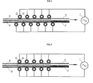
- the device of Figure 2 provides a field electric with maxima between the electrodic tubes in vis-à-vis and minima in the middle of the space separating electrodic tubes.
- Product progress between conveyor belts returns entails the application to this one of an alternating electric field of amplitude maximum variable at minimum and maximum. This can present a particular interest for certain materials.
- the device of Figure 3 makes it possible to obtain a field particularly homogeneous electric on the product to impregnate, close to that observed with electrodes flatter, even more homogeneous than the gap between the tubes rectangular electrodes is weak.
- the device of FIG. 4 also makes it possible to obtain an electric field with maxima and minima.
- the method of the invention can be used to impregnate various substrates, fibrous, filamentous and / or porous networks, with powders of different natures and of different chemical, functional and geometric characteristics.
- Different types of powder can be used in the process of the invention.
- the natures of these powders vary according to the final applications sought.
- the insulating powders are the easiest to use although it has been shown that a conductive powder could also be electrically charged and so be impregnated in a fibrous network by the action of the field electrostatic alternating.
- powders based on organic polymers as well as mineral powders work well and are often used in the process.
- the granulometry is the paramount parameter in the choice of a powder.
- the tests carried out made it possible to impregnate powders whose particle size ranges from 0.1 to 500 ⁇ m. In any case, the size of the powder particles will have to be compatible with the porosity of the fibrous or porous network to obtain a impregnation of the network.
- Fibrous, filamentous and / or porous networks can to be nonwovens, fabrics, knits, papers, leather, foams, wood fibers or all structures with sufficient porosity to allow the diffusion of powders by the action of the forces electrostatic alternatives.
- This process can be used to impregnate functional powders such as soaps, super absorbents, fire powders that will allow to use the substrate thus impregnated as a product functional in different end applications (hygiene, cosmetics, transport, building etc.).
- the quantity of powder to be impregnated be variable from 0.2% to 100% of the substrate mass according to the desired effects.
- posterior fixation technique for impregnated powders may be required to allow the realized product to retain its final characteristics.
- This process can also be used to impregnate binder or tacky powders in the fibrous network or porous.
- the powder will be distributed in the substrate in order to allow a fixation of the network in the sought geometry. For this, a later stage of heat setting may be required to allow the powder to join on the network and keep the structure in the desired configuration.
- the amount of binding powder sticky used in this type of application vary from 0.5% to 30% of the mass of the substrate following characteristics sought.
- the nature of powders used for these applications may be from the family of polyurethanes, co-polyesters, co-polyamides, that different thermoplastics and thermosets having adhesion or bonding characteristics.
- This method can also be used to realize reinforced materials constituting a continuous matrix, rigid or flexible in contact with the fibrous network or porous.
- the powder constitutes the matrix that will to provide fiber networks with very high mechanical properties to use the products impregnated obtained as composite materials.
- Powders used may have characteristics thermoplastics like polypropylene, polyethylene for example or thermosetting characteristics like phenolic or epoxy powders for example.
- the quantities of powders required to make these materials impregnated substances range from 5% to 200% of the initial mass of substrate. These impregnated materials require a step posterior formatting that can be performed, by example, by hot pressing.
- thermoplastics thermosetting and functional using the process of the invention carried out with devices with different configurations electrode.
- This example is made with a natural fiber nonwoven of 1000g / m 2 and 9 mm thick hemp and thermosetting powder Bakélite brand 6171TP reference of particle size less than 100 microns. A preliminary dusting of 500g / m 2 of powder is carried out on the upper face of the nonwoven.
- the set is then introduced into the process impregnation between two mats at a speed of 2 meters per minute.
- the electrodes used are electrodes tubular 30mm outer diameter which are arranged in opposite.
- the space separating the upper electrodes and lower is 10 mm between dielectrics.
- Space between two tubular electrodes of the same potential is 15 mm or 23 electrodes on each side for a length 1 meter treatment.
- a field of 3 kV / mm is applied in the space between the carpets where the material is to impregnate, to permeate.
- a residence time of 30 seconds in the machine makes it possible to obtain a homogeneous impregnation of the powder in the nonwoven.
- the material obtained is pressed to hot at 190 ° C for 1 minute with a pressure of 5 bar to obtain a composite material.
- This 2 mm material thick after pressing has a modulus of elasticity in average flexion of 4000 MPa.
- This example is made with a nonwoven spunlace viscose / polyester of 100g / m 2 .
- a super-absorbent reference powder JB 882 from SNF which has a particle size of less than 100 ⁇ m is sprinkled beforehand on the surface of the nonwoven.
- the speed of the mats to introduce the material in the impregnation machine is 4 m / min.
- impregnation time is therefore 15 seconds to get an impregnation of the superabsorbent in the nonwoven.
- the electrodes used are tubular electrodes of 30 mm outer diameter for the upper electrode and a flat electrode covered with a dielectric of 4 mm for the lower electrode.
- the space separating the upper and lower electrodes is 5 mm between dielectrics.
- the space between two tubular electrodes is 15 mm or 23 electrodes.
- the electrode bottom plate has a dimension of 1m x 1m.
- Field electrostatic applied to the product is 4 kV / mm.
- the impregnated powder is positioned between the fibers which allows to manipulate the material impregnated without observing significant loss of powder.
- the final capacity of the product obtained makes it possible to absorb an amount greater than 1500 g / m 2 of a saline solution at 0.9 g g / l of NaCl after immersion for 25 minutes in the latter.
- the objective of this example is to thermofix a polyester nonwoven after carding to provide sufficient mechanical strength to be handled and transported.
- the nonwoven is a polyester of 400g / m 2 which has been carded and coated on a thickness of 50 mm.
- the heat-setting powder used is a copolyamide powder with a particle size of 80-200 ⁇ m from the company Abifor.
- the material is compressed to 30 mm between the mats to be introduced into the impregnation machine.
- the electrodes used are tubular electrodes of 30mm of outside diameter which are arranged in staggered rows.
- the space between two tubular electrodes of the same potential is 15 mm or 23 electrodes on each side for a treatment length of 1 meter.
- a speed of 2 m / min is used either an impregnation time of 30 seconds this which makes it possible to disperse all the powder thermolizing in the volume of the nonwoven.
- the electrostatic field applied to the material is of 2 kV / mm.
- a subsequent heat-setting step is performed in an oven at a temperature of 140 ° C for 3 minutes to obtain a material having good strength mechanics and good resilience in order to be used as thermal insulator.
- An acoustic insulation material is made by impregnating a nonwoven fabric made from recycled cotton fibers with phenolic thermosetting resin powders.
- the nonwoven is made from recycled cotton fibers that have been coated to obtain a specific weight of 500g / m 2 .
- the phenolic powder, with the reference 6993TP Bakelite society is sprinkled on the surface of the nonwoven before introduction into the impregnating machine.
- the electrodes used are tubular electrodes 30 mm in external diameter which are arranged opposite.
- the space between the upper and lower electrodes is 15 mm between dielectrics.
- the space between two tubular electrodes of the same potential is 15 mm or 23 electrodes on each side for a treatment length of 1 meter.
- a field of 2.5 kV / mm is applied in the space between the mats where the material to be impregnated is located.
- a treatment time of 30 seconds in the machine makes it possible to obtain a homogeneous impregnation of the powder in the nonwoven.
- the material obtained is pressed to hot at 180 ° C for 2 minutes with a space of 10 mm in order to obtain a material with good acoustic characteristics.
- This example is achieved by impregnating a 500g / m 2 cotton knit with a 2000/09 epoxy / polyester powder from Dakota-Coating. A quantity of 100 g / m 2 of this powder is previously sprinkled on the knit before introducing the assembly into the impregnating machine.
- the electrodes used are tubular electrodes of 30 mm outer diameter for the upper electrode and a flat electrode covered with a dielectric of 4 mm for the lower electrode.
- the space between the upper and lower electrodes is 5 mm between dielectrics.
- the space between two upper tubular electrodes is 15 mm or 23 electrodes for a treatment length of 1 meter.
- the lower flat electrode has a dimension of 1m x 1m.
- An electric field of 2.5 kV / mm is applied in the product to be impregnated. A time of 15 seconds makes it possible to impregnate the powder uniformly between the fibers.
- thermoform the knit by heating it to 170 ° C in a mold that will give it its definitive form.
Abstract
Description
La présente invention se rapporte à un nouveau procédé d'imprégnation d'un réseau fibreux, filamenteux et/ou poreux par de la poudre, notamment pour produire un matériau composite comprenant une matrice continue, rigide ou flexible, avec laquelle ledit réseau est en contact intime.The present invention relates to a new process for impregnating a filamentous fibrous network and / or porous by powder, in particular to produce a composite material comprising a continuous matrix, rigid or flexible, with which said network is in intimate contact.
Les matériaux composites renforcés par des fibres noyées dans des matrices thermoplastiques ou thermodurcissables sont une catégorie de matériaux extrêmement intéressante, permettant notamment de réaliser des matériaux présentant d'excellentes propriétés mécaniques pour des masses sensiblement inférieures à celles des métaux. En outre, ces matériaux sont obtenus par simple moulage, après avoir enrobé les fibres ou filaments de renfort de la résine destinée à constituer la matrice du matériau composite. Bien évidemment, les propriétés mécaniques du matériau composite ainsi obtenu sont fonction de la qualité de l'interface entre les fibres ou filaments de renfort et la matrice.Composite materials reinforced with fibers embedded in thermoplastic matrices or thermosets are a class of materials extremely interesting, produce materials with excellent mechanical properties for masses substantially lower than those of metals. In addition, these materials are obtained by simple molding, after coating the reinforcing fibers or filaments of the resin for constitute the matrix of the composite material. Good obviously, the mechanical properties of the material composite thus obtained are a function of the quality of the interface between the reinforcing fibers or filaments and the matrix.
Ceci suppose donc une bonne cohésion entre les fibres ou les filaments et la matrice. Deux facteurs permettent essentiellement de déterminer cette cohésion, il s'agit d'une part des propriétés d'adhésion entre la résine et les fibres ou filaments de renfort, c'est-à-dire du choix de la matière destinée à former la matrice et, d'autre part, du taux de vide à l'intérieur du composite. Ce second facteur résulte évidemment de la capacité que la résine présente pour s'infiltrer entre les fibres ou les filaments de la masse fibreuse. En effet, chaque fibre ou filament ou chaque portion de fibre ou de filament qui ne se trouve pas enrobée dans la matrice ne participe pas ou ne participe que partiellement aux propriétés mécaniques du matériau composite. Par conséquent, le taux de vide réduit d'autant les propriétés mécaniques du matériau composite.This presupposes a good cohesion between the fibers or filaments and the matrix. Two factors essentially allow to determine this cohesion, this is on the one hand the adhesion properties between the resin and reinforcing fibers or filaments, i.e. the choice of the material intended to form the matrix and, on the other hand, the vacuum rate inside the composite. This second factor obviously results from the ability that the resin presents to infiltrate between the fibers or filaments of the fibrous mass. In effect, each fiber or filament or each portion of fiber or filament that is not embedded in the matrix does not participate or participate only partially to the mechanical properties of the material composite. Therefore, the reduced vacuum rate all the mechanical properties of the composite material.
Les matériaux fibreux servant d'isolants acoustiques ou thermiques sont réalisés en collant ou thermocollant les fibres constituant le nontissé au point d'intersection entre les fibres. Ces matériaux peuvent être réalisés par passage du non tissé dans un bain de colle ou par utilisation de fibres ou de poudres thermocollantes. La difficulté dans le cas des poudres thermocollantes est d'utiliser un procédé qui permette de répartir les poudres aux points de croisement des fibres pour optimiser le collage tout en limitant la quantité de poudre utilisée.Fibrous materials used as acoustic insulators or thermals are made by gluing or fusible fibers constituting the nonwoven at the point of intersection between the fibers. These materials can be made by passage of the nonwoven in a bath of glue or by use of fusible fibers or powders. The difficulty in the case of fusible powders is to use a process that allows to distribute the powders at the crossover points of the fibers to optimize the collage while limiting the amount of powder used.
Les matériaux textiles fonctionnels nécessitent d'introduire un principe actif (antibactérien, anti-feu, super-absorbant ...) dans le textile de base. Ce principe actif peut se présenter sous forme de bains liquides ou sous forme de poudres sèches qui faudra imprégner dans le support textile. Le cas des principes actifs sous forme liquide présentent l'inconvénient de nécessiter une consommation d'énergie importante pour pouvoir être séchés tout en évaporant le solvant du bain. Les poudres n'ont pas ce type de problème mais sont parfois difficiles à répartir dans le textile de base de manière homogène et définitive.Functional textile materials require to introduce an active ingredient (antibacterial, anti-fire, super-absorbent ...) in the basic textile. This principle active may be in the form of liquid baths or in the form of dry powders which will have to impregnate textile support. The case of active principles in form liquid have the disadvantage of requiring a high energy consumption to be dried while evaporating the solvent from the bath. The powders do not have this type of problem but are sometimes difficult to spread in the basic textile in a homogeneous and definitive way.
WO 99/22920 décrit un procédé d'imprégnation de poudre à l'intérieur d'un réseau fibreux ou filamenteux caractérisé en ce que l'on place la poudre, d'une part et ledit réseau de fibres ou de filaments, d'autre part, dans un champ électrostatique dont la tension alternative est d'au moins 5 kV pendant une durée d'au moins 2 s. Ce document décrit comme électrodes deux plaques métalliques superposées et parallèles connectées aux deux pôles respectifs d'un générateur électrostatique, dont les faces respectives disposées vis-à-vis l'une de l'autre sont recouvertes d'une plaque diélectrique, par exemple de vitrocéramique.WO 99/22920 discloses a method for impregnating powder inside a fibrous or filamentous network characterized in that the powder is placed on the one hand and said network of fibers or filaments, on the other hand, in an electrostatic field whose AC voltage is at least 5 kV for a period of at least 2 s. This document described as electrodes two metal plates superimposed and parallel connected to both poles of an electrostatic generator, the respective faces disposed opposite one another are covered with a dielectric plate, for example ceramic hob.
Ce procédé présente de nombreux avantages mais il est mal adapté au traitement d'objets à imprégner de grandes dimensions, par exemple de 0,80 à 2,50 m de large, en particulier lorsqu'on réalise le traitement en continu avec un matériau en défilement entre les électrodes. En effet, toute déformation géométrique des électrodes entraíne des écarts de distance entre celles-ci qui nuisent à l'homogénéité du champ électrique et donc à la qualité d'imprégnation des poudres. Pour éviter cette déformation géométrique, l'électrode plaque métallique inférieure peut être posée sur un bâtis; par contre l'électrode plaque métallique supérieure et le diélectrique qui la recouvre nécessitent donc d'être rigidifiés, par exemple par des barres transversales, ce qui peut nuire au fonctionnement des électrodes.This method has many advantages but it is poorly suited to the treatment of objects to impregnate large dimensions, for example from 0.80 to 2.50 m wide, in particular when performing continuous treatment with a material moving between the electrodes. Indeed, any geometric deformation of the electrodes leads to differences in distance between them which the homogeneity of the electric field and therefore the quality impregnation of the powders. To avoid this deformation geometric, the lower metal plate electrode can to be placed on a frame; on the other hand the electrode plate upper metal and the dielectric covering it therefore need to be rigidified, for example by transversal bars, which can affect the functioning electrodes.
La présente invention a pour but de proposer un procédé d'imprégnation de poudre à l'intérieur d'un réseau fibreux, filamenteux et/ou poreux, utilisant un champ électrique alternatif, qui soit adapté à l'imprégnation en continu d'objets de grandes dimensions, par exemple d'au moins 0,80 m, en particulier de 1,20-2,50 m, dans la direction perpendiculaire au défilement de l'objet à imprégner, sans présenter les inconvénients précités.The present invention aims to propose a powder impregnation process within a network fibrous, filamentous and / or porous, using a field alternatively, which is suitable for impregnation with of large objects, for example from minus 0.80 m, in particular from 1.20 to 2.50 m, in the direction perpendicular to the scrolling of the object to impregnate, without presenting the aforementioned drawbacks.
Ce but est atteint par l'invention telle que définie par le jeu ci-joint de revendications.This object is achieved by the invention as defined by the attached set of claims.
L'invention concerne un procédé d'imprégnation électrostatique de poudre à l'intérieur d'un réseau fibreux, filamenteux et/ou poreux par de la poudre, notamment pour produire un matériau composite, lié ou foctionnel, comprenant une matrice continue, rigide ou flexible, avec laquelle ledit réseau est en contact intime, dans lequel on place la poudre d'une part, et ledit réseau d'autre part, entre une électrode inférieure et une électrode supérieure, on isole électriquement par un diélectrique ces électrodes l'une de l'autre et on les relie respectivement aux pôles d'un générateur alternatif, afin de soumettre simultanément la poudre et ledit réseau à un champ électrostatique, caractérisé en ce que l'électrode supérieure comprend au moins un tube électrodique et le champ électrostatique alternatif appliqué est de 0,10 à 20 kV/mm.The invention relates to an impregnation process electrostatic powder inside a network fibrous, filamentous and / or porous by powder, particularly to produce a composite material, bound or focal, comprising a continuous matrix, rigid or flexible, with which said network is in contact intimate, in which the powder is placed on the one hand, and said network on the other hand, between a lower electrode and a top electrode, is electrically insulated by a dielectric these electrodes of each other and we connects to the poles of a generator alternative, in order to simultaneously subject the powder and said network to an electrostatic field, characterized in that that the upper electrode comprises at least one tube electrodic and the electrostatic alternating field applied is 0.10 to 20 kV / mm.
L'un des pôles du générateur alternatif est la phase, l'autre est le neutre, en général raccordé à la terre pour des raisons de sécurité, notamment lorsque le générateur alternatif est haute tension.One of the poles of the alternative generator is the phase, the other is the neutral, usually connected to the for security reasons, particularly when the Alternate generator is high voltage.
Le bon fonctionnement du procédé exige l'application sur le matériau à imprégner d'un champ électrostatique alternatif de 0,10 à 20 kV/mm. L'exigence d'obtenir un champ électrostatique élevé pour déplacer les particules de poudre nécessite en général l'utilisation d'un générateur haute tension alternative. Ce générateur peut être constitué d'un ou plusieurs transformateurs haute tension capable d'élever la tension délivrée par un variateur de tension primaire qui peut être lui-même constitué d'un autotransformateur. Ce variateur de tension primaire a pour fonction d'ajuster la tension qui va être élevée par le transformateur afin de constituer un générateur haute tension alternative à tension variable. Une solution consiste également à utiliser des dispositifs électroniques pour réaliser tout ou partie de ce générateur haute tension. La fréquence de ce générateur haute tension peut-être variable afin d'optimiser les performances d'imprégnation suivant la nature et la granulométrie de la poudre à imprégner. Cette fréquence pourra varier dans une plage de 1 Hertz à 1000 Hertz suivant les cas. La forme du signal électrique appliqué aux électrodes influence également l'imprégnation de la poudre. Des signaux carrés, sinusoïdaux ou triangles peuvent être employés ainsi que des signaux de formes plus complexes. En général on utilise une tension de signal sinusoïdale à 50 ou 60 Hertz afin d'utiliser un générateur haute tension économique.The proper functioning of the process requires the application on the material to be impregnated with an electrostatic field alternatively from 0.10 to 20 kV / mm. The requirement to obtain a high electrostatic field to move the particles of powder usually requires the use of a generator alternating high voltage. This generator can be consisting of one or more high-voltage transformers able to raise the voltage delivered by a dimmer primary voltage which may itself consist of a autotransformer. This primary voltage variator function to adjust the voltage that will be raised by the transformer in order to constitute a high generator alternating voltage with variable voltage. A solution also involves using electronic devices to realize all or part of this high generator voltage. The frequency of this high voltage generator may be variable to optimize performance impregnation according to the nature and the granulometry of the powder to be impregnated. This frequency may vary in a range from 1 Hertz to 1000 Hertz depending on the case. The shape of electrical signal applied to the electrodes influence also the impregnation of the powder. Square signals, sinusoidal or triangles can be used as well as signals of more complex shapes. In general we use a sinusoidal signal voltage at 50 or 60 Hertz so to use an economical high voltage generator.
Les électrodes sont constituées d'éléments fortement conducteurs pour garantir une tension équivalente en tout point de leur surface et minimiser les pertes par échauffement. Les métaux tels que par exemple le cuivre, l'aluminium, l'argent ou l'or sont avantageusement indiqués pour cela.Electrodes consist of elements strongly conductors to ensure equivalent voltage in all point of their surface and minimize losses by warming up. Metals such as for example copper, aluminum, silver or gold are advantageously indicated for that.
Un système d'isolants, encore appelé diélectrique, recouvre en général au moins une des électrodes afin de constituer une isolation électrique permettant de limiter le courant entre les électrodes et d'éviter l'apparition d'un arc électrique constituant un court-circuit lors de l'utilisation de champ électrique supérieur à la rigidité diélectrique de l'air. L'emploi de matériaux isolants est source de nombreux problèmes dans la conception ou la réalisation des matériels électriques. Une des principales causes de défaillance est, en effet, la rupture de l'isolation. En effet, lorsqu'un isolant est soumis à de fortes contraintes (électrique, thermique ou mécanique) il apparaít localement des zones non neutres en surface et/ou en volume qui modifient l'état électrique du matériau et induisent une distribution interne de champ résiduel. L'accumulation des charges d'espaces peut-être à l'origine de la dégradation du matériau et conduire au claquage de l'isolant.An insulation system, still called dielectric, generally covers at least one of the electrodes in order to constitute electrical insulation to limit the current between the electrodes and to avoid the appearance of an electric arc constituting a short circuit when the use of electric field greater than the rigidity dielectric of the air. The use of insulating materials is source of many problems in the design or the realization of electrical equipment. One of the main causes of failure is, in fact, the break in insulation. Indeed, when an insulation is subjected to strong constraints (electrical, thermal or mechanical) Locally appear non-neutral areas on the surface and / or in volume that alter the electrical state of the material and induce an internal residual field distribution. The accumulation of space charges may be causing degradation of the material and lead to the breakdown of the insulation.
Les isolants utilisés dans le procédé doivent présenter une rigidité diélectrique élevée et une bonne tenue en terme de vieillissement. Les matériaux comme le quartz, le verre ou la céramique présentent des caractéristiques intéressantes pour constituer ce diélectrique. Ces matériaux ont la faculté d'accumuler une faible quantité de charges d'espace lorsqu'ils sont soumis à un champ électrique. Le quartz est particulièrement apprécié comme isolant diélectrique car il présente une haute rigidité diélectrique et a une bonne tenue au vieillissement. Insulators used in the process must have high dielectric strength and good held in terms of aging. Materials like quartz, glass or ceramics exhibit interesting features to constitute this dielectric. These materials have the ability to accumulate a low amount of space charges when submitted to an electric field. Quartz is particularly appreciated as a dielectric insulator because it presents a high dielectric strength and has good resistance to aging.
L'épaisseur du diélectrique dépend du niveau de champ électrique appliqué sur les électrodes. Les épaisseurs de diélectrique de 1 mm à 20 mm conviennent, avec une préférence pour les épaisseurs comprises entre 2 et 5 mm.The thickness of the dielectric depends on the field level electric applied on the electrodes. The thicknesses of dielectric strength of 1 mm to 20 mm are suitable, with a preferably for thicknesses between 2 and 5 mm.
Suivant les niveaux de champ appliqués sur le matériau, il est possible d'isoler un seul pôle d'électrode ou les deux. L'isolation maximum sera obtenue avec un isolant diélectrique sur les deux pôles d'électrodes. Pour des matériaux pouvant être imprégnés avec un champ électrique inférieur à la tension de claquage de l'air, il est possible d'utiliser directement l'air comme isolant entre les électrodes métalliques. La bande transporteuse également être choisie pour servir de diélectrique avec une marge de sécurité suffisante par rapport au risque d'arc électrique.Depending on the field levels applied on the material, it is possible to isolate a single electrode pole or both. The maximum insulation will be obtained with a dielectric insulator on both electrode poles. For materials that can be impregnated with a field lower than the breakdown voltage of the air, it it is possible to use air directly as insulation between the metal electrodes. The conveyor belt also be chosen to serve as a dielectric with a sufficient margin of safety in relation to arc risk electric.
L'utilisation de résines fortement chargées de particules métalliques (laque d'argent par exemple) permet de réaliser directement un revêtement servant d'électrode à la surface de l'isolant diélectrique. De même l'utilisation de films métalliques recouverts d'adhésif permet d'appliquer directement l'électrode sur l'isolant diélectrique sans avoir de lame d'air entre l'électrode et le diélectrique. Une autre solution particulièrement intéressante consiste à métalliser directement l'isolant diélectrique à l'aide d'une des différentes techniques de métallisation bien connues dans l'art (métallisation sous vide PVD, ou CVD, métallisation chimique etc....). Là encore l'absence de lame d'air entre l'électrode et l'isolant diélectrique est favorable pour éviter des micro-décharges électriques entre les deux éléments. The use of resins heavily loaded with metal particles (silver lacquer for example) allows to make directly a coating serving as electrode to the surface of the dielectric insulator. Similarly the use of metal films covered with adhesive allows to directly apply the electrode to the insulation dielectric without having an air gap between the electrode and the dielectric. Another solution particularly interesting is to directly metallize the insulation dielectric using one of the different techniques of metallization well known in the art (metallization under vacuum PVD, or CVD, chemical metallization etc ....). Here again the lack of air gap between the electrode and the insulation dielectric is favorable to avoid micro-discharges between the two elements.
Selon l'invention, l'électrode supérieure comprend au moins un tube électrodique. La déformation au centre de cette électrode est ainsi fortement réduite ce qui permet de réaliser des traitements sur de grandes largeurs d'au moins 0,80 m, en particulier de 1,20-2,50 m.According to the invention, the upper electrode comprises at least one electrodic tube. The deformation at the center of this electrode is thus greatly reduced which allows to perform treatments over large widths from to minus 0.80 m, especially 1.20-2.50 m.
Le ou les tubes électrodiques peuvent présenter une section circulaire, rectangulaire ou une autre forme permettant d'appliquer un champ uniforme. Les tubes électrodiques sont en général constitués d'un diélectrique et d'une partie métallique.The electrodic tube or tubes may have a circular, rectangular section or another form to apply a uniform field. The tubes electrodes are usually made of a dielectric and a metal part.
Des tubes électrodiques particulièrement intéressants sont des tubes creux de diélectrique métallisés intérieurement, en particulier des tubes creux de quartz métallisés intérieurement. Des métaux tels que par exemple le cuivre, l'aluminium, l'argent ou l'or peuvent être utilisés pour cette métallisation.Especially interesting electrodic tubes are metallized dielectric hollow tubes internally, especially hollow quartz tubes metallized internally. Metals such as for example copper, aluminum, silver or gold can be used for this metallization.
Différentes configurations peuvent être utilisées pour disposer ces tubes et appliquer un champ électrostatique sur le produit à imprégner (cf. Figures 1 à 4 décrites ci-dessous). Dans des configurations d'électrodes avantageuses :
- les électrodes inférieures et supérieures sont constituées de tubes creux circulaires de diélectrique métallisés avec une configuration décalée de ces tubes (Figure 1) ou avec une configuration en vis à vis de ces tubes (Figure 2)
- les électrodes inférieures et supérieures sont constituées de tubes creux rectangulaires de diélectrique métallisés avec une configuration en vis à vis de ces tubes (Figure 3)
- l'électrode inférieure est une plaque rectangulaire et l'électrode supérieure est constituée de tubes creux circulaires de diélectrique métallisés (Figure 4).
- the lower and upper electrodes consist of circular hollow tubes of dielectric metallized with an offset configuration of these tubes (Figure 1) or with a configuration opposite these tubes (Figure 2)
- the lower and upper electrodes consist of rectangular hollow tubes of dielectric metallized with a configuration opposite these tubes (Figure 3)
- the lower electrode is a rectangular plate and the upper electrode consists of circular hollow tubes of dielectric metallized (Figure 4).
En fonction des matériaux, de la vitesse de défilement et du temps d'imprégnation recherché, un espacement plus ou moins important entre les tubes d'un même potentiel peut être retenu. Les vitesses d'imprégnation maximum sont obtenues avec un espacement très réduit entre les tubes d'un même potentiel.Depending on the materials, the speed of scrolling and the desired impregnation time, more spacing or less important between the tubes of the same potential can to be retained. The maximum impregnation speeds are obtained with a very small spacing between the tubes of the same potential.
L'obtention de l'effet d'imprégnation nécessite l'application du champ électrostatique alternatif pendant un temps suffisant. Celui-ci dépend notamment de la nature du réseau fibreux, filamenteux et/ou poreux et de la poudre, et des autres paramètres du procédé, en particulier l'intensité et la fréquence du champ alternatif, la forme des signaux, la configuration et les dimensions des électrodes. Ce temps suffisant sera facilement déterminé par l'homme du métier par des expériences de routine. En général il est d'au moins 1 s, souvent d'au moins 2 s, en particulier d'au moins 5 s.Obtaining the impregnation effect requires the application of the alternating electrostatic field during enough time. It depends in particular on the nature of the fibrous, filamentous and / or porous network and the powder, and other process parameters, in particular the intensity and frequency of the alternating field, the form signals, configuration and dimensions of electrodes. This sufficient time will be easily determined by the skilled person by routine experiments. In general it is at least 1 s, often at least 2 s, in particular of at least 5 s.
Une étape préalable au procédé consiste à saupoudrer la poudre à imprégner sur le dessus du support fibreux, filamenteux ou poreux. Le matériau ainsi constitué du support recouvert de la poudre peut être introduit dans le procédé afin de faire pénétrer la poudre dans son support. Dans certains cas, et notamment lorsque le support est très épais ou peu poreux, il est possible de réaliser un saupoudrage à la fois sur le dessus du support et/ou sur le dessous en saupoudrant tout ou partie de la poudre sur le tapis inférieur qui permet d'introduire le matériau dans le procédé.A preliminary step in the process consists in sprinkling the powder to be impregnated on the top of the fibrous support, filamentous or porous. The material thus constituted of the support covered with the powder can be introduced into the process to penetrate the powder in its support. In some cases, especially when the support is very thick or slightly porous, it is possible to dusting both on the top of the support and / or on the underneath by sprinkling all or part of the powder on the lower belt which allows to introduce the material into the process.
Le saupoudrage est généralement réalisé sur l'ensemble de la surface du support à imprégner. Dans certains cas, il est possible d'utiliser un saupoudrage localisé ou d'utiliser un pochoir pour imprégner uniquement certaines zones du support. Cet effet peut être recherché lorsque des pièces sont découpées dans l'utilisation finale du produit. Dans ce cas l'imprégnation localisée évite les pertes inutiles de poudre dans les chutes de matières qui peuvent ainsi être recyclées. Cet effet d'imprégnation localisé peut également être recherché pour obtenir des caractéristiques différentes suivants les zones du produit final (renfort ponctuel, traitement localisé...).Sprinkling is usually done on the whole of the surface of the support to be impregnated. In some cases, is possible to use a spot sprinkling or to use a stencil to impregnate only certain support areas. This effect can be sought when parts are cut into the end use of the product. In this case the localized impregnation avoids the losses unnecessary powder in the falls of materials that can thus be recycled. This localized impregnation effect can also be sought to obtain different characteristics following the product areas final (point reinforcement, localized treatment ...).
Le procédé peut être utilisé pour des imprégnations en défilement continu avec l'utilisation de deux bandes transporteuses réalisées en matériaux isolants comme du tissu de verre ou des polymères recouverts de polytétrafluoréthylène, de polyuréthane ou de silicone par exemple. L'utilisation de ces deux bandes transporteuses permet de prendre en sandwich le produit à imprégner en évitant la dispersion de la poudre et en évitant l'accumulation de la poudre à la surface des électrodes. L'utilisation de deux bandes transporteuses permet également de maintenir confinée la poudre sur le dessus du réseau fibreux lors de l'entrée du produit entre les électrodes. Dans le cas contraire, la poudre serait expulsée vers l'extérieur par le champ électrostatique.The process can be used for impregnations in continuous scrolling with the use of two tapes conveyors made of insulating materials such as glass fabric or polymers covered with polytetrafluoroethylene, polyurethane or silicone example. The use of these two conveyor belts allows to sandwich the product to be impregnated avoiding the dispersion of the powder and avoiding the accumulation of the powder on the surface of the electrodes. The use of two conveyor belts allows also to keep confined the powder on top of the fibrous network when entering the product between electrodes. Otherwise, the powder would be expelled to the outside by the electrostatic field.
Des dispositifs de nettoyage des bandes transporteuses en extrémité de machine permettent de récupérer la poudre qui pourrait rester présente à la surface des bandes. Ces systèmes de nettoyage peuvent utiliser des brosses et des systèmes d'aspiration. Dans tous les cas un collecteur permet de récupérer la poudre dans l'objectif de pouvoir la réintroduire en amont du procédé (saupoudrage du réseau fibreux, filamenteux et/ou poreux).Cleaning devices for conveyor belts at the end of the machine make it possible to recover the powder which could remain present on the surface of the bands. These cleaning systems can use brushes and suction systems. In all cases a collector allows to recover the powder in order to be able to reintroduce upstream of the process (sprinkling of the network fibrous, filamentous and / or porous).
D'autres particularités et avantages de la présente
invention apparaítront dans la description qui va suivre,
qui sera faite à l'aide des dessins annexés qui illustrent,
schématiquement et à titre d'exemple, la mise en oeuvre du
procédé de l'invention à l'aide de quatre configurations
d'électrodes.
Dans le dispositif de chacune des figures, de la
poudre 9 est saupoudrée préalablement à la surface du
matériau fibreux, filamenteux et/ou poreux 8, puis
introduit en continu dans le procédé d'imprégnation par
l'intermédiaire de deux bandes transporteuses 6 et 7. Le
générateur haute tension 1 est raccordé aux électrodes
supérieure et inférieure. La poudre est soumise à l'action
du champ électrostatique alternatif qui la fait imprégner
le réseau fibreux, filamenteux et/ou poreux, c'est-à-dire
pénétrer dans l'espace disponible de celui-ci. A la sortie
de l'applicateur, le matériau imprégné est utilisable pour
son application finale (moulage de composite,
thermofixation de matériaux d'isolation etc.).In the device of each of the figures, the
Le dispositif de la Figure 1 permet d'obtenir un champ électrique relativement homogène sur le produit à imprégner.The device of Figure 1 makes it possible to obtain a field relatively homogeneous electric on the product to to impregnate, to permeate.
Le dispositif de la Figure 2 permet d'obtenir un champ électrique avec des maxima entre les tubes électrodiques en vis-à-vis et des minima au milieu de l'espace séparant les tubes électrodiques. L'avancement du produit entre les bandes transporteuses revient entraíne l'application à celui-ci d'un champ électrique alternatif d'amplitude maximale variable à minima et maxima. Ceci peut présenter un intérêt particulier pour certains matériaux.The device of Figure 2 provides a field electric with maxima between the electrodic tubes in vis-à-vis and minima in the middle of the space separating electrodic tubes. Product progress between conveyor belts returns entails the application to this one of an alternating electric field of amplitude maximum variable at minimum and maximum. This can present a particular interest for certain materials.
Le dispositif de la Figure 3 permet d'obtenir un champ électrique particulièrement homogène sur le produit à imprégner, proche de celui observé avec des électrodes plates, d'autant plus homogène que l'écart entre les tubes rectangulaires électrodiques est faible.The device of Figure 3 makes it possible to obtain a field particularly homogeneous electric on the product to impregnate, close to that observed with electrodes flatter, even more homogeneous than the gap between the tubes rectangular electrodes is weak.
Le dispositif de la Figure 4 permet aussi d'obtenir un
champ électrique avec des maxima et des minima.
Le procédé de l'invention peut être utilisé pour imprégner
divers substrats, réseaux fibreux, filamenteux et/ou
poreux, avec des poudres de différentes natures et de
différentes caractéristiques chimiques, fonctionnelles, et
géométriques.The device of FIG. 4 also makes it possible to obtain an electric field with maxima and minima.
The method of the invention can be used to impregnate various substrates, fibrous, filamentous and / or porous networks, with powders of different natures and of different chemical, functional and geometric characteristics.
Différents types de poudre peuvent être utilisés dans le procédé de l'invention. Les natures de ces poudres varient suivant les applications finales recherchées. Les poudres de nature isolante sont les plus simples à utiliser bien qu'il ait été démontré qu'une poudre conductrice pouvait également se charger électriquement et ainsi être imprégnée dans un réseau fibreux par l'action du champ électrostatique alternatif. D'une manière générale, les poudres à base de polymères organiques ainsi que les poudres minérales fonctionnent bien et sont souvent utilisées dans le procédé. La granulométrie est le paramètre prépondérant dans le choix d'une poudre. Les essais réalisés ont permis d'imprégner des poudres dont la granulométrie varie de 0,1 à 500 µm. Dans tous les cas, la taille des particules de poudre devra être compatible avec la porosité du réseau fibreux ou poreux pour obtenir une imprégnation du réseau.Different types of powder can be used in the process of the invention. The natures of these powders vary according to the final applications sought. The insulating powders are the easiest to use although it has been shown that a conductive powder could also be electrically charged and so be impregnated in a fibrous network by the action of the field electrostatic alternating. In general, powders based on organic polymers as well as mineral powders work well and are often used in the process. The granulometry is the paramount parameter in the choice of a powder. The The tests carried out made it possible to impregnate powders whose particle size ranges from 0.1 to 500 μm. In any case, the size of the powder particles will have to be compatible with the porosity of the fibrous or porous network to obtain a impregnation of the network.
Il est également possible d'utiliser des mélanges de plusieurs poudres imprégnées en même temps dont la nature chimique ou les caractéristiques géométriques sont complémentaires pour l'usage final du matériau.It is also possible to use mixtures of several impregnated powders at the same time whose nature chemical or the geometric features are for the final use of the material.
Les réseaux fibreux, filamenteux et/ou poreux peuvent être des nontissés, des tissus, des tricots, des papiers, du cuir, des mousses, des fibres de bois ou toutes structures présentant une porosité suffisante pour permettre la diffusion de poudres par l'action des forces électrostatiques alternatives.Fibrous, filamentous and / or porous networks can to be nonwovens, fabrics, knits, papers, leather, foams, wood fibers or all structures with sufficient porosity to allow the diffusion of powders by the action of the forces electrostatic alternatives.
Ce procédé peut être utilisé pour imprégner des poudres fonctionnelles comme des savons, des super-absorbants, des poudres anti-feux qui permettront d'utiliser le substrat ainsi imprégné comme produit fonctionnel dans différentes applications finales (hygiène, cosmétiques, transports, bâtiment etc..). Dans ces différents cas, la quantité de poudre à imprégner pourra être variable de 0,2% à 100% de la masse de substrat suivant les effets recherchés. Dans certains cas, une technique de fixation postérieure des poudres imprégnées pourra être requise pour permettre au produit réalisé de conserver ses caractéristiques finales.This process can be used to impregnate functional powders such as soaps, super absorbents, fire powders that will allow to use the substrate thus impregnated as a product functional in different end applications (hygiene, cosmetics, transport, building etc.). In these different cases, the quantity of powder to be impregnated be variable from 0.2% to 100% of the substrate mass according to the desired effects. In some cases, posterior fixation technique for impregnated powders may be required to allow the realized product to retain its final characteristics.
Ce procédé peut également être utilisé pour imprégner des poudres liantes ou collantes dans le réseau fibreux ou poreux. Dans ce cas, la poudre sera répartie dans le substrat afin de permettre une fixation du réseau dans la géométrie recherchée. Pour cela, une étape postérieure de thermofixation peut être requise pour permettre à la poudre d'adhérer sur le réseau et de conserver la structure dans la configuration recherchée. La quantité de poudre liante ou collante utilisée dans ce type d'application pourra varier de 0,5% à 30% de la masse du substrat suivant les caractéristiques recherchées. La nature des poudres utilisées pour ces applications peut être de la famille des polyuréthanes, des co-polyesters, des co-polyamides, ainsi que des différents thermoplastiques et thermodurcissables présentant des caractéristiques d'adhésion ou de collage.This process can also be used to impregnate binder or tacky powders in the fibrous network or porous. In this case, the powder will be distributed in the substrate in order to allow a fixation of the network in the sought geometry. For this, a later stage of heat setting may be required to allow the powder to join on the network and keep the structure in the desired configuration. The amount of binding powder sticky used in this type of application vary from 0.5% to 30% of the mass of the substrate following characteristics sought. The nature of powders used for these applications may be from the family of polyurethanes, co-polyesters, co-polyamides, that different thermoplastics and thermosets having adhesion or bonding characteristics.
Ce procédé peut également être utilisé pour réaliser des matériaux renforcés constituant une matrice continue, rigide ou flexible en contact avec le réseau fibreux ou poreux. Dans ce cas, la poudre constitue la matrice qui va permettre d'apporter aux réseaux fibreux des propriétés mécaniques très élevés permettant d'utiliser les produits imprégnés obtenus comme matériaux composites. Les poudres utilisées peuvent avoir des caractéristiques thermoplastiques comme le polypropylène, le polyéthylène par exemple ou des caractéristiques thermodurcissables comme les poudres phénoliques ou époxydes par exemple. Les quantités de poudres requises pour réaliser ces matériaux imprégnés varient de 5% à 200% de la masse initiale de substrat. Ces matériaux imprégnés nécessitent une étape postérieure de mise en forme qui peut être réalisée, par exemple, par pressage à chaud.This method can also be used to realize reinforced materials constituting a continuous matrix, rigid or flexible in contact with the fibrous network or porous. In this case, the powder constitutes the matrix that will to provide fiber networks with very high mechanical properties to use the products impregnated obtained as composite materials. Powders used may have characteristics thermoplastics like polypropylene, polyethylene for example or thermosetting characteristics like phenolic or epoxy powders for example. The quantities of powders required to make these materials impregnated substances range from 5% to 200% of the initial mass of substrate. These impregnated materials require a step posterior formatting that can be performed, by example, by hot pressing.
Nous allons maintenant examiner quelques exemples de matériaux réalisés à l'aide de différents substrats tissés et nontissés et différentes poudres thermoplastiques, thermodurcissables et fonctionnelles à l'aide du procédé de l'invention mis en oeuvre avec des dispositifs comportant différentes configurations d'électrodes.We will now examine some examples of materials made using different substrates woven and nonwoven and different powders thermoplastics, thermosetting and functional using the process of the invention carried out with devices with different configurations electrode.
Cet exemple est réalisé avec un nontissé de fibres naturelles en chanvre de 1000g/m2 et de 9 mm d'épaisseur et avec de la poudre thermodurcissable de marque Bakélite référence 6171TP de granulométrie inférieure à 100 µm. Un saupoudrage préliminaire de 500g/m2 de poudre est réalisé sur le face supérieure du nontissé.This example is made with a natural fiber nonwoven of 1000g / m 2 and 9 mm thick hemp and thermosetting powder Bakélite brand 6171TP reference of particle size less than 100 microns. A preliminary dusting of 500g / m 2 of powder is carried out on the upper face of the nonwoven.
L'ensemble est ensuite introduit dans le procédé
d'imprégnation entre deux tapis à la vitesse de 2 mètres
par minute. Les électrodes utilisées sont des électrodes
tubulaires de 30mm de diamètre extérieur qui sont disposées
en vis à vis. L'espace séparant les électrodes supérieures
et inférieures est de 10 mm entre diélectriques. L'espace
entre deux électrodes tubulaires de même potentiel est de
15 mm soit 23 électrodes de chaque coté pour une longueur
de traitement de 1 mètre. Un champ de 3 kV/mm est appliqué
dans l'espace entre les tapis où se trouve le matériau à
imprégner. Un temps de séjour de 30 secondes dans la
machine permet d'obtenir une imprégnation homogène de la
poudre dans le nontissé.The set is then introduced into the process
impregnation between two mats at a speed of 2 meters
per minute. The electrodes used are electrodes
tubular 30mm outer diameter which are arranged
in opposite. The space separating the upper electrodes
and lower is 10 mm between dielectrics. Space
between two tubular electrodes of the same potential is
15 mm or 23 electrodes on each side for a
Après imprégnation, le matériau obtenu est pressé à chaud à 190°C pendant 1 minute avec une pression de 5 bars afin d'obtenir un matériau composite. Ce matériau de 2 mm d'épaisseur après pressage présente un module d'élasticité en flexion moyen de 4 000 MPa.After impregnation, the material obtained is pressed to hot at 190 ° C for 1 minute with a pressure of 5 bar to obtain a composite material. This 2 mm material thick after pressing has a modulus of elasticity in average flexion of 4000 MPa.
Cet exemple est réalisé avec un nontissé spunlace viscose/polyester de 100g/m2. Une poudre super-absorbante de référence JB 882 de la société SNF qui a une granulométrie inférieure à 100 µm est saupoudrée préalablement à la surface du nontissé.This example is made with a nonwoven spunlace viscose / polyester of 100g / m 2 . A super-absorbent reference powder JB 882 from SNF which has a particle size of less than 100 μm is sprinkled beforehand on the surface of the nonwoven.
La vitesse des tapis permettant d'introduire la matière dans la machine d'imprégnation est de 4 m/min.. Le temps d'imprégnation est donc de 15 secondes pour obtenir une imprégnation du super-absorbant dans le nontissé. Les électrodes utilisées sont des électrodes tubulaires de 30 mm de diamètre extérieur pour l'électrode supérieur et une électrode plate recouverte d'un diélectrique de 4 mm pour l'électrode inférieure. L'espace séparant les électrodes supérieures et inférieures est de 5 mm entre diélectriques. L'espace entre deux électrodes tubulaires supérieures est de 15 mm soit 23 électrodes. L'électrode plate inférieure a une dimension de 1m x 1m. Le champ électrostatique appliqué sur le produit est de 4 kV/mm.The speed of the mats to introduce the material in the impregnation machine is 4 m / min. impregnation time is therefore 15 seconds to get an impregnation of the superabsorbent in the nonwoven. The electrodes used are tubular electrodes of 30 mm outer diameter for the upper electrode and a flat electrode covered with a dielectric of 4 mm for the lower electrode. The space separating the upper and lower electrodes is 5 mm between dielectrics. The space between two tubular electrodes is 15 mm or 23 electrodes. The electrode bottom plate has a dimension of 1m x 1m. Field electrostatic applied to the product is 4 kV / mm.
On constate que la poudre imprégnée se positionne entre les fibres ce qui permet de manipuler le matériau imprégné sans observer de perte significative de poudre.It is found that the impregnated powder is positioned between the fibers which allows to manipulate the material impregnated without observing significant loss of powder.
La capacité finale du produit obtenu permet d'absorber une quantité supérieure à 1500g/m2 d'une solution saline à 0,9g g/l de NaCl après une immersion de 25 minutes dans cette dernière.The final capacity of the product obtained makes it possible to absorb an amount greater than 1500 g / m 2 of a saline solution at 0.9 g g / l of NaCl after immersion for 25 minutes in the latter.
L'objectif de cet exemple est de réaliser une thermofixation d'un nontissé en polyester après cardage afin de lui apporter une résistance mécanique suffisante pour être manipulé et transporté. Le nontissé est un polyester de 400g/m2 qui a été cardé et nappé sur une épaisseur de 50 mm. La poudre thermoliante utilisée est une poudre en copolyamide de granulométrie 80-200 µm de la société Abifor.The objective of this example is to thermofix a polyester nonwoven after carding to provide sufficient mechanical strength to be handled and transported. The nonwoven is a polyester of 400g / m 2 which has been carded and coated on a thickness of 50 mm. The heat-setting powder used is a copolyamide powder with a particle size of 80-200 μm from the company Abifor.
Après la phase de saupoudrage à la surface du nontissé, le matériau est comprimé à 30 mm entre les tapis afin d'être introduit dans la machine d'imprégnation. Les électrodes utilisées sont des électrodes tubulaires de 30mm de diamètre extérieur qui sont disposées en quinconce. L'espace entre deux électrodes tubulaires de même potentiel est de 15 mm soit 23 électrodes de chaque côté pour une longueur de traitement de 1 mètre. Une vitesse de 2 m/min est utilisée soit un temps d'imprégnation de 30 secondes ce qui permet de disperser l'ensemble de la poudre thermoliante dans le volume du nontissé.After the dusting phase on the surface of the nonwoven, the material is compressed to 30 mm between the mats to be introduced into the impregnation machine. The electrodes used are tubular electrodes of 30mm of outside diameter which are arranged in staggered rows. The space between two tubular electrodes of the same potential is 15 mm or 23 electrodes on each side for a treatment length of 1 meter. A speed of 2 m / min is used either an impregnation time of 30 seconds this which makes it possible to disperse all the powder thermolizing in the volume of the nonwoven.
Le champ électrostatique appliqué sur le matériau est de 2 kV/mm.The electrostatic field applied to the material is of 2 kV / mm.
Une étape postérieure de thermofixation est réalisée dans un four à une température de 140°C pendant 3 minutes afin d'obtenir un matériau présentant une bonne solidité mécanique et une bonne résilience afin d'être utilisé comme isolant thermique.A subsequent heat-setting step is performed in an oven at a temperature of 140 ° C for 3 minutes to obtain a material having good strength mechanics and good resilience in order to be used as thermal insulator.
Un matériau servant d'isolant acoustique est réalisé en imprégnant un nontissé à base de fibres de coton recyclées avec des poudres de résines thermodurcissables phénoliques. Le nontissé est issu de fibres de coton recyclées qui ont été nappées afin d'obtenir un poids spécifique de 500g/m2. La poudre phénolique, avec la référence 6993TP de la société Bakélite, est saupoudrée à la surface du nontissé avant introduction dans la machine d'imprégnation. Les électrodes utilisées sont des électrodes tubulaires de 30mm de diamètre extérieur qui sont disposées en vis à vis. L'espace séparant les électrodes supérieures et inférieures est de 15 mm entre diélectriques. L'espace entre deux électrodes tubulaires de même potentiel est de 15 mm soit 23 électrodes de chaque coté pour une longueur de traitement de 1 mètre. Un champ de 2,5 kV/mm est appliqué dans l'espace entre les tapis ou se trouve le matériau à imprégner. Un temps de traitement de 30 secondes dans la machine permet d'obtenir une imprégnation homogène de la poudre dans le nontissé.An acoustic insulation material is made by impregnating a nonwoven fabric made from recycled cotton fibers with phenolic thermosetting resin powders. The nonwoven is made from recycled cotton fibers that have been coated to obtain a specific weight of 500g / m 2 . The phenolic powder, with the reference 6993TP Bakelite society is sprinkled on the surface of the nonwoven before introduction into the impregnating machine. The electrodes used are tubular electrodes 30 mm in external diameter which are arranged opposite. The space between the upper and lower electrodes is 15 mm between dielectrics. The space between two tubular electrodes of the same potential is 15 mm or 23 electrodes on each side for a treatment length of 1 meter. A field of 2.5 kV / mm is applied in the space between the mats where the material to be impregnated is located. A treatment time of 30 seconds in the machine makes it possible to obtain a homogeneous impregnation of the powder in the nonwoven.
Après imprégnation, le matériau obtenu est pressé à chaud à 180°C pendant 2 minutes avec un espace de 10 mm afin d'obtenir un matériau présentant de bonnes caractéristiques acoustiques.After impregnation, the material obtained is pressed to hot at 180 ° C for 2 minutes with a space of 10 mm in order to obtain a material with good acoustic characteristics.
Cet exemple est réalisé en imprégnant un tricot en coton de 500g/m2 avec une poudre époxy/polyester référence 2000/09 de la société Dakota-Coating. Une quantité de 100g/m2 de cette poudre est préalablement saupoudrée sur le tricot avant d'introduire l'ensemble dans la machine d'imprégnation. Les électrodes utilisées sont des électrodes tubulaires de 30 mm de diamètre extérieur pour l'électrode supérieur et une électrode plate recouverte d'un diélectrique de 4 mm pour l'électrode inférieure. L'espace séparant les électrodes supérieures et inférieures est de 5 mm entre diélectriques. L'espace entre deux électrodes tubulaires supérieures est de 15 mm soit 23 électrodes pour une longueur de traitement de 1 mètre. L'électrode plate inférieure a une dimension de 1m x 1m. Un champ électrique de 2,5 kV/mm est appliqué dans le produit à imprégner. Un temps de 15 secondes permet d'imprégner uniformément la poudre entre les fibres.This example is achieved by impregnating a 500g / m 2 cotton knit with a 2000/09 epoxy / polyester powder from Dakota-Coating. A quantity of 100 g / m 2 of this powder is previously sprinkled on the knit before introducing the assembly into the impregnating machine. The electrodes used are tubular electrodes of 30 mm outer diameter for the upper electrode and a flat electrode covered with a dielectric of 4 mm for the lower electrode. The space between the upper and lower electrodes is 5 mm between dielectrics. The space between two upper tubular electrodes is 15 mm or 23 electrodes for a treatment length of 1 meter. The lower flat electrode has a dimension of 1m x 1m. An electric field of 2.5 kV / mm is applied in the product to be impregnated. A time of 15 seconds makes it possible to impregnate the powder uniformly between the fibers.
Une étape postérieure permet de thermoformer le tricot en le chauffant à 170°C dans un moule qui lui donnera sa forme définitive.A later stage makes it possible to thermoform the knit by heating it to 170 ° C in a mold that will give it its definitive form.
Claims (10)
Priority Applications (14)
| Application Number | Priority Date | Filing Date | Title |
|---|---|---|---|
| EP03292607A EP1526214A1 (en) | 2003-10-21 | 2003-10-21 | Process and device for impreganting a fibre network with powder material in an electrostatic field with alternating current |
| TW093131119A TW200519244A (en) | 2003-10-21 | 2004-10-14 | Process for impregnating a fibrous, filamentary and/or porous network with powder using electrodes subjected to an AC electric field |
| DE602004021956T DE602004021956D1 (en) | 2003-10-21 | 2004-10-18 | METHOD AND DEVICE FOR IMPREGNATING A FIBER NETWORK WITH POWDER IN AN ELECTROSTATIC FIELD WITH AC VOLTAGE |
| AT04769679T ATE435938T1 (en) | 2003-10-21 | 2004-10-18 | METHOD AND DEVICE FOR IMPREGNATION OF A FIBER NETWORK WITH POWDER IN AN ELECTROSTATIC FIELD WITH ACTING VOLTAGE |
| PCT/IB2004/003427 WO2005038123A1 (en) | 2003-10-21 | 2004-10-18 | Method and device for impregnating a fibrous web with a powder using an alternating electrostatic field |
| JP2006536205A JP2007509250A (en) | 2003-10-21 | 2004-10-18 | Method for impregnating a fibrous web with powder using an alternating electrostatic field |
| EP04769679A EP1678372B1 (en) | 2003-10-21 | 2004-10-18 | Process and device for impreganting a fibre network with powder material in an electrostatic field with alternating current |
| CNB2004800309861A CN100415983C (en) | 2003-10-21 | 2004-10-18 | Process for impregnating a fibrous, filamentary and/or porous network with powder using electrodes subjected to an AC electric field |
| BRPI0415658-7A BRPI0415658A (en) | 2003-10-21 | 2004-10-18 | process for impregnating a fibrous, filamentous and / or porous network with dust using electrodes subjected to an electric field of ca |
| AU2004281321A AU2004281321B2 (en) | 2003-10-21 | 2004-10-18 | Method and device for impregnating a fibrous web with a powder using an alternating electrostatic field |
| KR1020067007632A KR20060110275A (en) | 2003-10-21 | 2004-10-18 | Method and device for impregnating a fibrous web with a powder using an alternating electrostatic field |
| US11/408,082 US7534473B2 (en) | 2003-10-21 | 2006-04-20 | Process for impregnating a fibrous, filamentary and/or porous network with powder using electrodes subjected to an AC electric field |
| IL175057A IL175057A0 (en) | 2003-10-21 | 2006-04-20 | Method and device for impregnating a fibrous web with a powder using an alternating electrostatic field |
| ZA200604027A ZA200604027B (en) | 2003-10-21 | 2006-05-18 | Method and device for impregnating a fibrous web with a powder using an alterating electrostatic field |
Applications Claiming Priority (1)
| Application Number | Priority Date | Filing Date | Title |
|---|---|---|---|
| EP03292607A EP1526214A1 (en) | 2003-10-21 | 2003-10-21 | Process and device for impreganting a fibre network with powder material in an electrostatic field with alternating current |
Publications (1)
| Publication Number | Publication Date |
|---|---|
| EP1526214A1 true EP1526214A1 (en) | 2005-04-27 |
Family
ID=34384700
Family Applications (2)
| Application Number | Title | Priority Date | Filing Date |
|---|---|---|---|
| EP03292607A Withdrawn EP1526214A1 (en) | 2003-10-21 | 2003-10-21 | Process and device for impreganting a fibre network with powder material in an electrostatic field with alternating current |
| EP04769679A Not-in-force EP1678372B1 (en) | 2003-10-21 | 2004-10-18 | Process and device for impreganting a fibre network with powder material in an electrostatic field with alternating current |
Family Applications After (1)
| Application Number | Title | Priority Date | Filing Date |
|---|---|---|---|
| EP04769679A Not-in-force EP1678372B1 (en) | 2003-10-21 | 2004-10-18 | Process and device for impreganting a fibre network with powder material in an electrostatic field with alternating current |
Country Status (13)
| Country | Link |
|---|---|
| US (1) | US7534473B2 (en) |
| EP (2) | EP1526214A1 (en) |
| JP (1) | JP2007509250A (en) |
| KR (1) | KR20060110275A (en) |
| CN (1) | CN100415983C (en) |
| AT (1) | ATE435938T1 (en) |
| AU (1) | AU2004281321B2 (en) |
| BR (1) | BRPI0415658A (en) |
| DE (1) | DE602004021956D1 (en) |
| IL (1) | IL175057A0 (en) |
| TW (1) | TW200519244A (en) |
| WO (1) | WO2005038123A1 (en) |
| ZA (1) | ZA200604027B (en) |
Cited By (21)
| Publication number | Priority date | Publication date | Assignee | Title |
|---|---|---|---|---|
| WO2007110524A1 (en) * | 2006-03-28 | 2007-10-04 | Fibroline France | Pprocess for producing a stampable reinforced composite semi-finished product |
| EP1875822A1 (en) * | 2006-07-07 | 2008-01-09 | Fibroline France | Stiffener capable of being thermofused to a substrate and process for its manufacture |
| WO2008049980A1 (en) * | 2006-10-27 | 2008-05-02 | Fibroline France | Composite reinforcement for impregnation or coating |
| FR2917430A1 (en) * | 2007-06-12 | 2008-12-19 | Fibroline France Sarl | METHOD FOR MANUFACTURING SOIL COATING AND SOIL COATING |
| WO2010001043A1 (en) * | 2008-07-02 | 2010-01-07 | Fibroline France | Device and method for impregnating a porous material with powder |
| WO2013152809A1 (en) | 2012-04-13 | 2013-10-17 | Libeltex | Unitary absorbent structures comprising an absorbent core and/or an acquisition and dispersion layer for absorbent articles |
| FR3013740A1 (en) * | 2013-11-22 | 2015-05-29 | Fibroline France | INSTALLATION AND METHOD FOR IMPREGNATING A POROUS TEXTILE SUPPORT WITH POWDER |
| FR3029445A1 (en) * | 2014-12-09 | 2016-06-10 | Fibroline France | INSTALLATION FOR IMPREGNATING A POROUS SUPPORT COMPRISING OPTIMIZED COATED ELECTRODES |
| WO2016177960A1 (en) * | 2015-05-04 | 2016-11-10 | Fibroline | Panel for covering and/or soundproofing a wall of a vehicle and associated method of manufacture |
| EP3153141A1 (en) | 2015-10-06 | 2017-04-12 | Fameccanica.Data S.p.A. | A method and apparatus for producing an absorbent structure |
| WO2017192866A1 (en) | 2016-05-04 | 2017-11-09 | Somnio Global Holdings, Llc | Additive fabrication methods and devices for manufacture of objects having preform reinforcements |
| WO2017207135A1 (en) | 2016-05-31 | 2017-12-07 | Drylock Technologies Nv | Absorbent structure comprising release structure |
| WO2019038291A1 (en) | 2017-08-22 | 2019-02-28 | Eco - Technilin Sas | Material with a sandwich-type structure to be thermocompressed and manufacturing methods thereof |
| EP3466387A1 (en) | 2017-10-09 | 2019-04-10 | Drylock Technologies NV | Method and apparatus for manufacturing an absorbent structure |
| CN110809515A (en) * | 2017-07-05 | 2020-02-18 | 通用电气公司 | Enhanced through-thickness resin infusion for wind turbine composite laminates |
| US11273598B2 (en) | 2020-03-18 | 2022-03-15 | Powder Motion Labs, LLC | Powder bed recoater |
| WO2022058696A1 (en) * | 2020-09-21 | 2022-03-24 | Fibroline | Facility for powder impregnation of at least one yarn and/or ribbon type substrate to be treated |
| US11407172B2 (en) | 2020-03-18 | 2022-08-09 | Powder Motion Labs, LLC | Recoater using alternating current to planarize top surface of powder bed |
| EP4052890A1 (en) | 2021-03-02 | 2022-09-07 | L'Air Liquide, société anonyme pour l'Étude et l'Exploitation des procédés Georges Claude | Method of manufacturing a composite tank of pressurised fluid and tank |
| US11612940B2 (en) | 2020-03-18 | 2023-03-28 | Powder Motion Labs, LLC | Powder bed recoater |
| WO2023111353A1 (en) | 2021-12-17 | 2023-06-22 | Medskin Solutions Dr. Suwelack Ag | Composition comprising a biomaterial-based porous material coated with a powder |
Families Citing this family (17)
| Publication number | Priority date | Publication date | Assignee | Title |
|---|---|---|---|---|
| FR2909029B1 (en) | 2006-11-27 | 2011-10-21 | Solvay | METHOD FOR MANUFACTURING A COMPOSITE PLATE BASED ON PVC AND STRUCTURE INCLUDING SUCH A PLATE |
| DE202007000262U1 (en) * | 2007-01-02 | 2007-04-19 | Brandchemie Gmbh | Fireproofing material, e.g. for cable, walls, ducts or pipes, comprises a semi-finished fibre product with a high softening temperature, treated and-or coated on one or both sides with fire retardant |
| US20090286437A1 (en) * | 2008-05-14 | 2009-11-19 | Kimberly-Clark Worldwide, Inc. | Wipes with rupturable beads |
| FR2948895B1 (en) | 2009-08-06 | 2011-09-09 | Solvay | MANUFACTURE AND USE OF A PROFILE REINFORCED IN THERMOPLASTIC MATERIAL |
| DE102011011387B8 (en) | 2011-02-17 | 2013-09-19 | Daimler Ag | Process for producing a multilayer fiber-plastic composite semifinished product |
| WO2012139973A2 (en) | 2011-04-11 | 2012-10-18 | Solvay Sa | Multilayer structure comprising fibres and a vinyl chloride polymer |
| JP2014510820A (en) | 2011-04-11 | 2014-05-01 | ソルヴェイ(ソシエテ アノニム) | Production and use of composites comprising fibers and at least one vinyl chloride polymer |
| FR3010931B1 (en) * | 2013-09-26 | 2015-09-25 | Fibroline France | INSTALLATION AND METHOD FOR IMPREGNATION BY TRANSFERRING A POWDER INTO A POROUS SUPPORT |
| JP6266305B2 (en) * | 2013-10-31 | 2018-01-24 | ユニチカ株式会社 | Sheet molding compound and molded product using the same |
| FR3016169B1 (en) * | 2014-01-09 | 2017-12-15 | Biomerieux Sa | METHOD FOR DETECTION, IDENTIFICATION AND DETECTION OF MICROORGANISMS IN A POROUS SUPPORT DRY IMPREGNATED BY A REACTIONAL MEDIUM DEHYDRATE |
| US9566605B2 (en) * | 2015-01-20 | 2017-02-14 | R.J. Reynolds Tobacco Products | Humidity control insert for cigarette packs |
| WO2016203641A1 (en) * | 2015-06-19 | 2016-12-22 | 株式会社ダイセル | Method for manufacturing opened fiber material formed of long fiber tow |
| CN110873737A (en) * | 2018-09-03 | 2020-03-10 | 株式会社斯巴鲁 | Resin impregnation measurement system |
| CN111376500A (en) * | 2018-12-29 | 2020-07-07 | 浙江华江科技股份有限公司 | Efficient low-pollution GMT powder scattering device and using method thereof |
| KR102469561B1 (en) * | 2020-12-01 | 2022-11-22 | (주)원투비씨에스티 | Thermoplastics powder resin impreganting system and impreganting Method |
| EP4197417A1 (en) | 2021-12-14 | 2023-06-21 | VERMOP Salmon GmbH | Method for manufacturing a cleaning textile and a wiping cloth |
| WO2023196599A1 (en) * | 2022-04-07 | 2023-10-12 | Biodaptive Advanced Materials, Llc | Method and system for integrating an additive to a substrate |
Citations (6)
| Publication number | Priority date | Publication date | Assignee | Title |
|---|---|---|---|---|
| US2730455A (en) * | 1952-10-30 | 1956-01-10 | Carl C Swann | Method of coating fibers, threads, and/or filamentary material |
| US3919437A (en) * | 1972-02-22 | 1975-11-11 | Owens Corning Fiberglass Corp | Method for electrostatically impregnating strand |
| EP0179688A1 (en) * | 1984-09-26 | 1986-04-30 | Pradom Limited | Method of making composite materials and products obtained thereby |
| US5895622A (en) * | 1997-04-07 | 1999-04-20 | Purdue Research Foundation | Method and apparatus for composite manufacture |
| EP0914916A1 (en) * | 1997-11-04 | 1999-05-12 | Materials Technics Société Anonyme Holding | Method for producing a composite material |
| WO2002030657A1 (en) * | 2000-10-13 | 2002-04-18 | Barsmark A/S | A method, an apparatus and a matrix for making composite plates |
Family Cites Families (5)
| Publication number | Priority date | Publication date | Assignee | Title |
|---|---|---|---|---|
| JP2001214366A (en) * | 1999-07-15 | 2001-08-07 | Sekisui Chem Co Ltd | Nonwoven fabric and method for producing the same, separator using the nonwoven fabric and used for secondary battery and method for producing the same |
| JP4161533B2 (en) * | 2000-12-28 | 2008-10-08 | 松下電工株式会社 | Plasma processing method and plasma processing apparatus |
| US7247338B2 (en) * | 2001-05-16 | 2007-07-24 | Regents Of The University Of Minnesota | Coating medical devices |
| JP4019712B2 (en) * | 2002-01-09 | 2007-12-12 | コニカミノルタホールディングス株式会社 | Plasma discharge treatment apparatus and plasma discharge treatment method |
| EP1525969A1 (en) * | 2003-10-21 | 2005-04-27 | Materials Technics Holding | Process and device for mixing, dispersing and/or homogenizing powder material |
-
2003
- 2003-10-21 EP EP03292607A patent/EP1526214A1/en not_active Withdrawn
-
2004
- 2004-10-14 TW TW093131119A patent/TW200519244A/en unknown
- 2004-10-18 KR KR1020067007632A patent/KR20060110275A/en not_active Application Discontinuation
- 2004-10-18 CN CNB2004800309861A patent/CN100415983C/en not_active Expired - Fee Related
- 2004-10-18 DE DE602004021956T patent/DE602004021956D1/en not_active Expired - Fee Related
- 2004-10-18 BR BRPI0415658-7A patent/BRPI0415658A/en not_active IP Right Cessation
- 2004-10-18 AU AU2004281321A patent/AU2004281321B2/en not_active Expired - Fee Related
- 2004-10-18 WO PCT/IB2004/003427 patent/WO2005038123A1/en active Application Filing
- 2004-10-18 AT AT04769679T patent/ATE435938T1/en not_active IP Right Cessation
- 2004-10-18 JP JP2006536205A patent/JP2007509250A/en active Pending
- 2004-10-18 EP EP04769679A patent/EP1678372B1/en not_active Not-in-force
-
2006
- 2006-04-20 IL IL175057A patent/IL175057A0/en unknown
- 2006-04-20 US US11/408,082 patent/US7534473B2/en not_active Expired - Fee Related
- 2006-05-18 ZA ZA200604027A patent/ZA200604027B/en unknown
Patent Citations (6)
| Publication number | Priority date | Publication date | Assignee | Title |
|---|---|---|---|---|
| US2730455A (en) * | 1952-10-30 | 1956-01-10 | Carl C Swann | Method of coating fibers, threads, and/or filamentary material |
| US3919437A (en) * | 1972-02-22 | 1975-11-11 | Owens Corning Fiberglass Corp | Method for electrostatically impregnating strand |
| EP0179688A1 (en) * | 1984-09-26 | 1986-04-30 | Pradom Limited | Method of making composite materials and products obtained thereby |
| US5895622A (en) * | 1997-04-07 | 1999-04-20 | Purdue Research Foundation | Method and apparatus for composite manufacture |
| EP0914916A1 (en) * | 1997-11-04 | 1999-05-12 | Materials Technics Société Anonyme Holding | Method for producing a composite material |
| WO2002030657A1 (en) * | 2000-10-13 | 2002-04-18 | Barsmark A/S | A method, an apparatus and a matrix for making composite plates |
Cited By (49)
| Publication number | Priority date | Publication date | Assignee | Title |
|---|---|---|---|---|
| US8388780B2 (en) | 2006-03-28 | 2013-03-05 | Fibroline France | Process for producing a stampable reinforced composite semi-finished product |
| FR2899146A1 (en) * | 2006-03-28 | 2007-10-05 | Materials Technics Holding Sa | Stampable semi-finished reinforced composite production, by sprinkling plastics powder particles onto fibers or filaments on conveyor and blending while applying electric field |
| WO2007110524A1 (en) * | 2006-03-28 | 2007-10-04 | Fibroline France | Pprocess for producing a stampable reinforced composite semi-finished product |
| KR101410528B1 (en) * | 2006-03-28 | 2014-06-20 | 파이브로라인 프랑스 | Process for producing a stampable reinforced composite semi-finished product |
| CN101410245A (en) * | 2006-03-28 | 2009-04-15 | 法国费保利内 | Pprocess for producing a stampable reinforced composite semi-finished product |
| CN101410245B (en) * | 2006-03-28 | 2013-05-29 | 法国费保利内 | Process for producing a stampable reinforced composite semi-finished product |
| EP1875822A1 (en) * | 2006-07-07 | 2008-01-09 | Fibroline France | Stiffener capable of being thermofused to a substrate and process for its manufacture |
| WO2008007212A1 (en) * | 2006-07-07 | 2008-01-17 | Fibroline France | Reinforcement heat-bondable to a support, and method of its manufacture |
| WO2008049980A1 (en) * | 2006-10-27 | 2008-05-02 | Fibroline France | Composite reinforcement for impregnation or coating |
| WO2009004202A1 (en) * | 2007-06-12 | 2009-01-08 | Fibroline France | Method for making a textile coating and textile coating |
| US9011981B2 (en) | 2007-06-12 | 2015-04-21 | Fibroline France | Method for making a textile covering and textile covering |
| RU2455410C2 (en) * | 2007-06-12 | 2012-07-10 | Фибролайн Франс | Method to manufacture textile cover and textile cover |
| FR2917430A1 (en) * | 2007-06-12 | 2008-12-19 | Fibroline France Sarl | METHOD FOR MANUFACTURING SOIL COATING AND SOIL COATING |
| US8967079B2 (en) | 2008-07-02 | 2015-03-03 | Fibroline France | Device and method for impregnating a porous material with powder |
| FR2933327A1 (en) * | 2008-07-02 | 2010-01-08 | Fibroline France | INSTALLATION AND METHOD FOR IMPREGNATING POROUS MATERIAL WITH POWDER |
| CN102083599B (en) * | 2008-07-02 | 2013-11-06 | 法国费保利内 | Device and method for impregnating a porous material with powder |
| RU2486055C2 (en) * | 2008-07-02 | 2013-06-27 | Фибролайн Франс | Device and method of impregnating porous materials with powder |
| CN102083599A (en) * | 2008-07-02 | 2011-06-01 | 法国费保利内 | Device and method for impregnating a porous material with powder |
| WO2010001043A1 (en) * | 2008-07-02 | 2010-01-07 | Fibroline France | Device and method for impregnating a porous material with powder |
| WO2013152809A1 (en) | 2012-04-13 | 2013-10-17 | Libeltex | Unitary absorbent structures comprising an absorbent core and/or an acquisition and dispersion layer for absorbent articles |
| FR3013740A1 (en) * | 2013-11-22 | 2015-05-29 | Fibroline France | INSTALLATION AND METHOD FOR IMPREGNATING A POROUS TEXTILE SUPPORT WITH POWDER |
| RU2685317C2 (en) * | 2014-12-09 | 2019-04-17 | Фибролин | Device for impregnation of a porous medium containing optimized coated electrodes |
| WO2016092205A1 (en) * | 2014-12-09 | 2016-06-16 | Fibroline France | Apparatus for impregnating a porous medium comprising optimized coated electrodes |
| FR3029445A1 (en) * | 2014-12-09 | 2016-06-10 | Fibroline France | INSTALLATION FOR IMPREGNATING A POROUS SUPPORT COMPRISING OPTIMIZED COATED ELECTRODES |
| AU2015359222B2 (en) * | 2014-12-09 | 2020-03-12 | Fibroline | Apparatus for impregnating a porous medium comprising optimized coated electrodes |
| WO2016177960A1 (en) * | 2015-05-04 | 2016-11-10 | Fibroline | Panel for covering and/or soundproofing a wall of a vehicle and associated method of manufacture |
| US10821917B2 (en) | 2015-05-04 | 2020-11-03 | Howa Tramico | Panel for covering and/or soundproofing a wall of a vehicle and associated method of manufacture |
| EP3153141A1 (en) | 2015-10-06 | 2017-04-12 | Fameccanica.Data S.p.A. | A method and apparatus for producing an absorbent structure |
| US10682267B2 (en) | 2015-10-06 | 2020-06-16 | Fameccanica, Data S.P.A. | Method and apparatus for producing an absorbent structure |
| US11116677B2 (en) | 2015-10-06 | 2021-09-14 | Fameccanica, Data S.P A. | Method and apparatus for producing an absorbent structure |
| WO2017192866A1 (en) | 2016-05-04 | 2017-11-09 | Somnio Global Holdings, Llc | Additive fabrication methods and devices for manufacture of objects having preform reinforcements |
| EP3452272A4 (en) * | 2016-05-04 | 2020-01-01 | Somnio Global Holdings, LLC | Additive fabrication methods and devices for manufacture of objects having preform reinforcements |
| US11529268B2 (en) | 2016-05-31 | 2022-12-20 | Drylock Technologies Nv | Absorbent structure comprising release structure |
| WO2017207135A1 (en) | 2016-05-31 | 2017-12-07 | Drylock Technologies Nv | Absorbent structure comprising release structure |
| CN110809515A (en) * | 2017-07-05 | 2020-02-18 | 通用电气公司 | Enhanced through-thickness resin infusion for wind turbine composite laminates |
| WO2019038291A1 (en) | 2017-08-22 | 2019-02-28 | Eco - Technilin Sas | Material with a sandwich-type structure to be thermocompressed and manufacturing methods thereof |
| EP3466387A1 (en) | 2017-10-09 | 2019-04-10 | Drylock Technologies NV | Method and apparatus for manufacturing an absorbent structure |
| WO2019072765A1 (en) | 2017-10-09 | 2019-04-18 | Drylock Technologies Nv | Method and apparatus for manufacturing an absorbent structure |
| US11612940B2 (en) | 2020-03-18 | 2023-03-28 | Powder Motion Labs, LLC | Powder bed recoater |
| US11407172B2 (en) | 2020-03-18 | 2022-08-09 | Powder Motion Labs, LLC | Recoater using alternating current to planarize top surface of powder bed |
| US11607846B2 (en) | 2020-03-18 | 2023-03-21 | Powder Motion Labs, LLC | Recoater using alternating current to planarize top surface of powder bed |
| US11273598B2 (en) | 2020-03-18 | 2022-03-15 | Powder Motion Labs, LLC | Powder bed recoater |
| US11772164B2 (en) | 2020-03-18 | 2023-10-03 | Powder Motion Labs, LLC | Powder bed recoater |
| US11872754B2 (en) | 2020-03-18 | 2024-01-16 | Powder Motion Labs, LLC | Recoater using alternating current to planarize top surface of powder bed |
| FR3114261A1 (en) * | 2020-09-21 | 2022-03-25 | Fibroline | POWDER IMPREGNATION INSTALLATION OF AT LEAST ONE WIRE AND/OR TAPE TYPE SUPPORT TO BE TREATED |
| WO2022058696A1 (en) * | 2020-09-21 | 2022-03-24 | Fibroline | Facility for powder impregnation of at least one yarn and/or ribbon type substrate to be treated |
| EP4052890A1 (en) | 2021-03-02 | 2022-09-07 | L'Air Liquide, société anonyme pour l'Étude et l'Exploitation des procédés Georges Claude | Method of manufacturing a composite tank of pressurised fluid and tank |
| FR3120326A1 (en) | 2021-03-02 | 2022-09-09 | L'air Liquide, Societe Anonyme Pour L'etude Et L'exploitation Des Procedes Georges Claude | Method of manufacturing a composite pressurized fluid reservoir and reservoir |
| WO2023111353A1 (en) | 2021-12-17 | 2023-06-22 | Medskin Solutions Dr. Suwelack Ag | Composition comprising a biomaterial-based porous material coated with a powder |
Also Published As
| Publication number | Publication date |
|---|---|
| US20060233966A1 (en) | 2006-10-19 |
| WO2005038123A1 (en) | 2005-04-28 |
| CN100415983C (en) | 2008-09-03 |
| EP1678372B1 (en) | 2009-07-08 |
| CN1871397A (en) | 2006-11-29 |
| AU2004281321A1 (en) | 2005-04-28 |
| BRPI0415658A (en) | 2006-12-19 |
| ZA200604027B (en) | 2007-09-26 |
| ATE435938T1 (en) | 2009-07-15 |
| EP1678372A1 (en) | 2006-07-12 |
| KR20060110275A (en) | 2006-10-24 |
| AU2004281321B2 (en) | 2009-09-17 |
| JP2007509250A (en) | 2007-04-12 |
| TW200519244A (en) | 2005-06-16 |
| DE602004021956D1 (en) | 2009-08-20 |
| US7534473B2 (en) | 2009-05-19 |
| IL175057A0 (en) | 2006-08-20 |
Similar Documents
| Publication | Publication Date | Title |
|---|---|---|
| EP1678372B1 (en) | Process and device for impreganting a fibre network with powder material in an electrostatic field with alternating current | |
| EP1028836B1 (en) | Method for impregnating a fibre or filament array with powder, in particular for producing a composite material | |
| EP1246958B1 (en) | Method for producing a complex nonwoven fabric and resulting novel fabric | |
| JP5302182B2 (en) | How to produce stampable reinforced composite semi-finished products | |
| EP2834060A2 (en) | Material with improved conductivity properties for the production of composite parts in combination with a resin | |
| EP0395548A1 (en) | Textil reinforcement for making moulded composite materials and articles with reinforcement | |
| EP0681620A1 (en) | Method for producing a nonwoven and nonwoven thereby obtained | |
| EP0406353B1 (en) | Textile reinforcement for composite materials and method for obtaining them | |
| EP1373621A1 (en) | Method and device for making a composite sheet with multiaxial fibrous reinforcement | |
| EP2841341B1 (en) | Use of a stack to improve the transverse electric conductivity of a composite component | |
| FR3061067A1 (en) | METHOD FOR MANUFACTURING PRE-IMPREGNATED FIBROUS MATERIAL OF THERMOPLASTIC POLYMER THROUGH PROJECTION | |
| EP2467524B1 (en) | Textile armature of continuous glass filaments | |
| CA2061805C (en) | Composite covering textile and manufacturing process | |
| EP2467518A2 (en) | Reinforcement comprising parallel rovings of glass strands | |
| CH684726B5 (en) | Product comprising a fibrous structure having separate groups of fibers showing a higher density. | |
| FR2961514A1 (en) | CURABLE PRE-IMPREGNE COMPRISING A METALLIC COATED POLYMER SHEET WITH OPEN STRUCTURE | |
| EP0394081B1 (en) | Method for producing a composite comprising a thermoplastic matrix reinforced with long fibres, and composite obtained by this method | |
| EP0636728B1 (en) | Process for manufacturing a glass mat with filaments | |
| BE630083A (en) | ||
| WO2005045113A2 (en) | Deformable mat with fibrous reinforcement for the production of thermoplastic matrix composites | |
| EP2961583A1 (en) | Preparation of a semi-finished textile product intended for thermoplastic injection moulding, and resulting product |
Legal Events
| Date | Code | Title | Description |
|---|---|---|---|
| PUAI | Public reference made under article 153(3) epc to a published international application that has entered the european phase |
Free format text: ORIGINAL CODE: 0009012 |
|
| AK | Designated contracting states |
Kind code of ref document: A1 Designated state(s): AT BE BG CH CY CZ DE DK EE ES FI FR GB GR HU IE IT LI LU MC NL PT RO SE SI SK TR |
|
| AX | Request for extension of the european patent |
Extension state: AL LT LV MK |
|
| AKX | Designation fees paid | ||
| REG | Reference to a national code |
Ref country code: DE Ref legal event code: 8566 |
|
| STAA | Information on the status of an ep patent application or granted ep patent |
Free format text: STATUS: THE APPLICATION IS DEEMED TO BE WITHDRAWN |
|
| 18D | Application deemed to be withdrawn |
Effective date: 20051028 |