EP1526356B1 - Method for Measuring Curved Surface of a Workpiece - Google Patents
Method for Measuring Curved Surface of a Workpiece Download PDFInfo
- Publication number
- EP1526356B1 EP1526356B1 EP04024863A EP04024863A EP1526356B1 EP 1526356 B1 EP1526356 B1 EP 1526356B1 EP 04024863 A EP04024863 A EP 04024863A EP 04024863 A EP04024863 A EP 04024863A EP 1526356 B1 EP1526356 B1 EP 1526356B1
- Authority
- EP
- European Patent Office
- Prior art keywords
- workpiece
- measuring
- curved surface
- coordinate system
- theoretical
- Prior art date
- Legal status (The legal status is an assumption and is not a legal conclusion. Google has not performed a legal analysis and makes no representation as to the accuracy of the status listed.)
- Expired - Fee Related
Links
Images


Classifications
-
- G—PHYSICS
- G01—MEASURING; TESTING
- G01B—MEASURING LENGTH, THICKNESS OR SIMILAR LINEAR DIMENSIONS; MEASURING ANGLES; MEASURING AREAS; MEASURING IRREGULARITIES OF SURFACES OR CONTOURS
- G01B21/00—Measuring arrangements or details thereof, where the measuring technique is not covered by the other groups of this subclass, unspecified or not relevant
- G01B21/02—Measuring arrangements or details thereof, where the measuring technique is not covered by the other groups of this subclass, unspecified or not relevant for measuring length, width, or thickness
- G01B21/04—Measuring arrangements or details thereof, where the measuring technique is not covered by the other groups of this subclass, unspecified or not relevant for measuring length, width, or thickness by measuring coordinates of points
Definitions
- the present invention relates to a method for measuring a curved surface of a workpiece, particularly to a method for measuring a curved surface of a workpiece so as to avoid the interference between the workpiece and a measuring probe.
- a gear is cited as a representative example of a workpiece having such a curved surface and, particularly in the final speed reducer of an automobile or the like, gears such as spiral bevel gears and hypoid gears having tooth flanks of curved surfaces are frequently used as gears to change the direction of a rotation axis and reduce the speed in the transmission of rotation power.
- a spiral bevel gear is configured so that a ring gear and a pinion engage with each other and their axes intersect with each other on the same plane as shown in Fig. 20.
- a hypoid gear although a ring gear and a pinion engage with each other likewise, their axes do not intersect with each other on the same plane and so-called offset is incorporated.
- the features of a hypoid gear are that it has a high degree-of-freedom of spatial allocation in a power transmission system and moreover allows smoother rotation, quieter operation and also higher tooth strength than a spiral bevel gear.
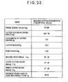
- gear generation is executed with a gear generator based on the theoretical machine setting parameters shown in Fig. 22.
- a gear generator based on the theoretical machine setting parameters shown in Fig. 22.
- a gear pair showing good tooth bearing can not always be obtained due to the mechanical errors and the like of a gear generator.
- a cutter 1 of a gear generator is supported by a cradle 2 so as to be rotatable around the cutter axis zc.
- the base material of a ring gear blank as a workpiece W is supported by a workpiece head 3 so as to be rotatable but the workpiece W does not rotate and is fixed while a tooth of the ring gear is in cutting operation.
- the coordinate system shown in Fig. 23 includes: a machine coordinate system consisting of an origin point Om being the center of a machine, cradle axis (zm axis), H axis (ym axis) and V axis (xm axis: an axis passing through the origin point Om and being perpendicular to the cradle axis (zm axis) and the H axis); and a cutter coordinate system consisting of an origin point Oc being the center of a cutter and xc, yc and zc axes (refer to Fig. 25).
- a gear coordinate system consisting of an origin point Og being the center of a gear and xg, yg and zg axes (refer to Fig. 25).
- the workpiece axis zg and the cradle axis zm are on the same plane and the machine center Om coincides with the gear center Og.
- the offset between the V axis (xm axis) and the xc axis is represented by Hg and the offset between the H axis (ym axis) and the yc axis is represented by Vg.
- Xgc shows the position vector on the locus of a cutting blade edge formed when the cutting blade edge of a cutter 1 rotates around the cutter center Oc.
- Fig. 25 The mutual relationship among the coordinate systems on the ym-zm plane is as shown in Fig. 25.
- the distance from the reference plane Wb of a workpiece to the gear center Og (V axis) is represented by Lg and a machine root angle (an angle formed by the ym axis and the zg axis) is represented by ⁇ gr.
- Mi the i-th measured data
- Mi X ⁇ ui , vi , C ⁇ 1 + ⁇ C ⁇ 1 , C ⁇ 2 + ⁇ C ⁇ 2 , ... , Cn + ⁇ Cn
- the difference between the measured tooth flank data M and a value given by the theoretical tooth flank expression X is determined as residual (M-X).
- an angle ⁇ can be obtained in addition to the estimated machine setting parameters (C1+ ⁇ C1, C2+ ⁇ C2, ..., Cn+ ⁇ Cn) by the aforementioned method and therefore it becomes possible to transform the theoretical tooth flank expression into a measurement coordinate system.
- ⁇ is subordinate to all the gear cutting parameters (C1, C2, ..., Cn)
- the unknowns of C1, C2, ..., Cn and ⁇ , namely n + 1 in total are not solved by simultaneous equations, they are solved by applying dual simultaneous equations related to the least-square method to each combination of ( ⁇ and C1), ( ⁇ and C2), ..., ( ⁇ and Cn), namely n combinations in total.
- WO 02/23292 relates to a method for generating a measuring program for a co-ordinate measuring device.
- a CAD data set of an object to be measured is inputted into a data processing device which controls a co-ordinate measuring device.
- measuring of the object to be measured can be automized and the stylus angle of the measuring touch probe can be automatically adjusted to the orientation of the measuring area.
- An main object of the present invention is to provide: a method for measuring a curved surface of a workpiece that allows to measure with safety and a high degree of accuracy the measurement points of the workpiece having a curved surface such as a tooth flank of a spiral bevel gear; a program thereof; and a medium thereof.
- the axis angle of the stylus of the probe in the event of measuring the curved surface of the workpiece is determined based on the theoretical expression of a workpiece, the measurement can be carried out safely and easily without interference between the probe and the workpiece.
- the computing load can be mitigated.
- the reliability in the computation of the axis angle in the measuring area can be improved. That is, as long as the axis angle is obtained through the above procedure, the interference between the workpiece and the measuring probe can surely be avoided.
- the interference between the workpiece and the measuring probe can further surely be avoided.
- the axis angle is determined based on the shape of the workpiece, the interference between the workpiece and the measuring probe can yet further surely be avoided.
- a measurement part program including a stylus axis angle control command is generated based on the theoretical expression of the workpiece, it is possible to prepare the measurement part program beforehand even before the completion of the machining of the workpiece itself and to start the measurement operation immediately after the completion of the machining of the workpiece, and resultantly the overall production efficiency improves.
- the three-dimensional coordinate values on an objective measuring plane can be obtained even before the completion of the workpiece machining.
- Fig. 1 shows a first embodiment of a method for measuring a curved surface of a workpiece by using a coordinate measuring machine according to the present invention and a measurement system 10 is composed of the coordinate measuring machine 100, a controller 200 a the computer 300.
- the coordinate measuring machine 100 is equipped with an X axis beam 104 spanned across a column 102 and a supporter 103, those being placed at both ends of a measurement table 101. Further, it is equipped with an X axis slider 106 (X axis transfer mechanism) that is supported by the X axis beam 104 via air bearings and movable in the X axis direction and a Z axis spindle 107 (Z axis transfer mechanism) that is supported by the X axis slider 106 via air bearings and movable in the Z axis direction.
- the column 102 and the supporter 103 are also supported afloat by the measurement table 101 via air bearings.
- the column 102 is guided in the Y axis direction by a Y axis guide mechanism 105, which is installed at one end of the measurement table 101, via air bearings and therefore the column 102 and the supporter 103 are movable in an integrated manner in the Y axis direction (Y axis transfer mechanism).
- each of the X axis slider 106, the column 102 and the supporter 103, and the Z axis spindle 107 is detectable by a respective linear scale.
- the X, Y and Z axes are in the relation of intersecting with each other at right angles.
- a touch signal probe 110 is attached to a bottom end of the Z axis spindle 107 and a spherical contact tip 112 is attached to a tip of a stylus 111 thereof.
- a workpiece W (ring gear of a hypoid gear) is mounted on the measurement table 101 and a touch signal is output by bringing the spherical contact tip 112 of the touch signal probe into contact with a tooth flank thereof and the displacement of each of the X, Y and Z axis transfer mechanisms at that moment is read by the respective linear scale and output as the measured data.
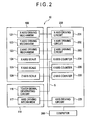
- Fig. 2 shows a block diagram of a major electrical control unit in the measurement system 10.
- the coordinate measuring machine 100 is equipped with an X axis driving mechanism 121, a Y axis driving mechanism 122 and a Z axis driving mechanism 123, those being driven by motors, and the X axis slider 106, the column 102 and the supporter 103, and the Z axis spindle 107 are driven by the respective driving mechanisms.
- the displacement of those sliders is detected by an X axis scale 124, a Y axis scale 125 and a Z axis scale 126, respectively.
- the controller 200 is equipped with an X axis driving circuit 201 that drives the motor of the X axis driving mechanism 121, a Y axis driving circuit 202 that drives the motor of the Y axis driving mechanism 122, and a Z axis driving circuit 203 that drives the motor of the Z axis driving mechanism 123.
- the scales of the axes of the coordinate measuring machine 100 are connected to an X axis counter 204, a Y axis counter 205 and a Z axis counter 206, respectively.
- each axis slider is counted by each of those axis counters and also counter values D (xi, yi and zi) of the axes are output as the measured data by a touch signal S generated in a touch signal generating circuit 116 of the touch signal probe 110.
- the touch signal probe 110 is equipped with an axis driving mechanism 117 as well as the touch signal generating circuit 116 and, as shown in Fig. 3, it is designed so that the axis 115 of the stylus 111 is tiltable in an arbitrary direction relative to the axis 114 of the probe body 113 of the touch signal probe 110.
- the axis driving mechanism 117 is composed of: a vertically tiltable driving mechanism that drives the axis 115 of the stylus 111 so as to tilt by an arbitrary angle ⁇ v to the axis 114 of the probe body 113; and a horizontally rotatable driving mechanism that drives the axis 115 of the stylus 111 so as to rotate by an arbitrary angle ⁇ h in a plane perpendicular to the axis 114 of the probe body 113.
- the axis driving mechanism 117 is driven by the axis driving circuit 225 of the controller 200.
- the computer 300 controls the three axis driving circuits 201 to 203 and the axis driving circuit 225 and also inputs the counter values D (xi, yi and zi) of the axes as measured tooth flank data Mi.
- the computer 300 is further equipped with various I/O devices (a keyboard, a mouse, a display, a printer, a circuit I/O device, an auxiliary memory, etc.), not shown in the figures, and makes it possible to do various I/O operations, the display and print of computed results and the like according to any purpose.
- I/O devices a keyboard, a mouse, a display, a printer, a circuit I/O device, an auxiliary memory, etc.
- Fig. 4 is a flowchart showing the procedure of the process in the case where a method for measuring a curved surface of a workpiece according to the present invention is carried out by the computer 300 and the procedure is hereunder explained by taking the case of measuring the tooth flank of a ring gear of a hypoid gear as the workpiece for instance.
- step S 10 the execution of the method for measuring a curved surface of a workpiece is started.
- step S20 basic parameters (for example, Fig. 21) and machine setting parameters (for example, Fig. 22) are input based on the design drawings and the like of a workpiece W (gear).
- the machine setting parameters may be replaced with theoretical values or values estimated from the results obtained by measuring an actual gear.
- a theoretical expression of the tooth flank of the gear is computed based on the basic parameters and the machine setting parameters.
- Xg, A (a coordinate transformation matrix related to rotation around an xm axis), Xgc (the position vector on a cutting blade edge), Dg (the position of the cutter center Oc in the coordinate system Om of a gear generator), and Ngc (a unit normal line on the cutting blade edge) are all vectors.
- u shows the rotating angle of a cutter 1 and v shows the distance from the cutter center Oc to the cutting blade edge.
- ⁇ gr shows a machine root angle (root cone angle) (refer to Fig. 25).
- the steps S20 and S30 compose the theoretical expression input steps.
- the theoretical expression is already known or when the shape expression is already derived from the analysis result of measured data, it is also acceptable to input directly the theoretical expression or the shape expression instead of the computation of the theoretical expression based on parameters such as designed values and the like and to use it as the theoretical expression at the succeeding steps.
- step S40 a measuring area is determined based on the theoretical expression.
- the tooth flank Xw of the workpiece W has a right flank Xw2 and a left flank Xw1 as shown in Fig. 6. Since these processing procedures of them are identical, the procedures in the case of measuring the left flank Xw1 are explained hereunder.
- a measuring area In the determination of a measuring area, one or more of measuring areas An are determined in a tooth flank area of the left flank Xw1.
- Various kinds of algorithms can be applied to this determination algorithm and in this case the measuring areas are determined by dividing the tooth flank equally in the tooth trace direction.
- Fig. 7 shows a tooth flank Xw1 and the measuring areas A1 and A2, divided into two equal pieces in the tooth trace direction, in which the left side of the drawing shows the inner side of the gear and the lower side thereof shows the root side of the tooth flank.
- step S50 the coordinate values and the normal vector at a representative point in each measuring area are computed.
- the algorithm of determining a representative point there are various methods. For example, it is a common practice to determine one point in the center of a measuring area in the case of measuring a tooth pitch, and one point each at the both ends of a measuring area, two points in total, in the case of measuring the shape of a tooth flank.
- the representative points Q11, Q12, Q21 and Q22 are determined at the both ends of the measuring areas A1 and A2 respectively at the center in the tooth depth direction of the tooth flank (the direction from the root to the tip of the tooth flank) and then coordinate values and the normal vector are computed for each representative point based on the theoretical expression.
- an internal angle ⁇ i formed at the intersection of the normal vectors N11 and N12 at the representative points Q11 and Q12 in the same measuring area is computed (refer to Fig. 8) and whether the internal angle ⁇ i is within a predetermined angle range or not is judged.
- the curvature of the tooth flank in the measuring area is judged to be small.
- the processing flow branches and goes to S80 and the axis angle of the stylus is determined.
- the curvature of the tooth flank in the measuring area is judged to be large. That is, if the measurement is executed in the measuring area with the same stylus axis angle ⁇ h without changing the stylus axis angle ⁇ h, it is judged that there arises the possibility of the interference between the workpiece W and the probe 110 and, in this case, the process flow branches and goes to S70 to divide the measuring area.
- Fig. 9 shows an example of the case where the measuring area A1 is divided into A11 and A12 by this method.
- step S70 After the measuring area is divided at step S70, the process flow returns to S50 and the coordinate values and the normal vector of the representative point in each measuring area are computed again.
- a tangent vector Tw is computed. If the teeth of a gear are not curving but straight as shown in Fig. 10 for example, assuming that the plane of the drawing is the horizontal plane, the axis angle ⁇ h of the stylus 111 in the horizontal plane is univocally determined in accordance with the tooth flank to be measured. In contrast, in the case of a spiral bevel gear, the tooth flank curves as shown in Fig. 6 for example and therefore it is necessary to determine an axis angle ⁇ h in accordance with the angle of the curvature of a measuring area.
- a tangent vector Tw in the tooth trace direction perpendicular to the normal vector Nw of the measuring area is determined, and the angle for parallelizing the plane that is tangent to a curved surface of a workpiece in the measuring area and also contains the tangent vector Tw (the plane perpendicular to the normal vector) and a plane that contains the axis 115 of the stylus 111 with each other is defined as the flank direction axis angle ⁇ h.
- a tangent vector may be determined by either method, the method of compounding the normal vectors of the representative points, computing a representative normal vector Nr of the measuring area, and determining a representative tangent vector Tr from this representative normal vector Nr (refer to Fig. 12), or the method of determining each tangent vector from each normal vector, compounding those tangent vectors, and then determining the representative tangent vector Tr (refer to Fig. 13), and the like.
- a slant axis angle ⁇ v (the axis angle in the tooth depth direction in the case of a bevel gear) is determined and this can be determined easily from the machine root angle ⁇ gr.
- the slant axis angle ⁇ v is determined based on the shape of the workpiece.
- the axis angles (the flank direction axis angle ⁇ h and the slant axis angle ⁇ v) are determined for each measuring area.
- the axis driving circuit 225 controls the axis driving mechanism 117 and the angles of the axis 115 of the stylus 111 are adjusted to ⁇ h and ⁇ v.
- the angles of the axis 115 of the stylus 111 are adjusted manually so as to be the angles ⁇ h and ⁇ v as indicated in a display.
- the measurement conditions include the kind of a probe 110 to be used (a touch signal probe/ a scanning probe), the maximum value/ control resolution of stylus axis angles ⁇ v and ⁇ h, whether or not a workpiece W is rotatably mounted on a rotary table, the diameter of a probe spherical contact tip 112, a retract distance (a distance from a workpiece W that allows the axis angles of a stylus 111 to change safely), kind of measurement (pitch measurement/ tooth flank shape measurement/ multiple tooth flank shape measurement), the number of tooth flanks to be measured, the direction of tooth flanks to be measured (right/ left), and the like.
- step S100 a measurement part program is generated.
- the measurement part program includes a stylus axis angle tuning command that tunes the axis angles of the stylus 111 by controlling the axis driving mechanism 117 via the axis driving circuit 225.
- a measurement part program conforming to the measuring probe is generated.
- the generated measurement part program is run by a measurement part program execution program (not shown in the figures) incorporated in the computer 300, the coordinate measuring machine 100 is controlled via the controller 200, and intended measured data are output from the controller 200.
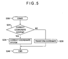
- step S110 the determination of a workpiece coordinate system is executed, which is required when an actual workpiece W is mounted on the coordinate measuring machine 100.
- step S 110 Detailed contents of the processing at step S 110 are shown in the flowchart of Fig. 5.
- the measurement part program generated at step S100 is generated by the theoretical coordinate system
- a workpiece coordinate system is determined. Since the workpiece coordinate system usually does not coincide with the theoretical coordinate system, it is necessary to conform the former coordinate system to the latter one or to transform the coordinate values of the measurement part program into the coordinate values of the workpiece.
- the conformation is executed at step S220.
- the coordinate transformation is executed at step S230.
- step S210 Those ramifications are carried out at step S210. Usually, an operator judges which case should be adopted.
- a workpiece coordinate system is once determined by temporarily adopting the coordinate system O of a coordinate measuring machine, thereafter one or more points of the workpiece W are subjected to measurement and, based on the result, the temporary workpiece coordinate system is corrected.
- the attitude of the workpiece W mounted on a measurement table 101 is not particularly regulated and, for simplicity, the explanations here are done on the premise that the workpiece W is a ring gear of a hypoid gear and it is mounted so that a reference plane Wb thereof abuts on the measurement table 101. Then, the configuration is determined so that the axis zg of the ring gear is parallel to the z axis of the coordinate measuring machine, the gear center Og is the origin point of the z axis of the coordinate measuring machine, and the axis zg of the ring gear takes the position of the origin point O of the x and y axes of the coordinate measuring machine.
- the position is identified at the height of pz so that the distance from the gear center on the xg-yg plane to the center position pg of the spherical contact tip 112 equals to Lt on the assumption that the spherical contact tip 112 is brought into contact with the theoretical tooth flank shown by the tooth flank expression (4) and the angle ⁇ g formed by the xg axis and the center position pg is computed.
- the direction of the straight line is defined as an xw axis (X axis of the workpiece coordinate system), a yw axis (Y axis of the workpiece coordinate system) that passes through the origin point O and is perpendicular to the xw axis is determined, and the Z axis is defined as a zw axis (Z axis of the workpiece coordinate system) as it is.
- the plural workpiece coordinate systems are identified, and the workpiece coordinate system Ow is determined by averaging the plural workpiece coordinate systems, a workpiece coordinate system with a higher degree of accuracy can be established.
- the coordinate transformation is carried out at step S230.
- the workpiece coordinate system is not rotated, the workpiece coordinate system is determined while the direction of the straight line O-p is regarded as the direction of the xw axis as it is, and the coordinate values and the axis angles of the measurement part program are rotated by an angle of - ⁇ g around the zg axis.
- Embodiment 2 is the case where the computer 300 of Embodiment 1 is replaced with a computer 400 and other configurations thereof are the same as Embodiment 1.
- Fig. 17 shows the block diagram of the computer 400.
- the coordinate system determination circuit 410 is composed of a coordinate system correction judgment circuit (the same operation as S210), a coordinate system correction circuit (the same operation as S220), and a coordinate transformation circuit (the same operation as S230).
- each circuit contains a memory circuit of a predetermined capacity in which various kinds of input data and computation results are stored according to need.
- the computer 400 is further equipped with various I/O devices (a keyboard, a mouse, a display, a printer, a circuit I/O device, an auxiliary memory, etc.), not shown in the figures, and makes it possible to do various operations, the display and print of computed results and the like according to any purpose.
- I/O devices a keyboard, a mouse, a display, a printer, a circuit I/O device, an auxiliary memory, etc.
- the measurement part program generated in the program generation circuit 409 is executed by a measurement part program execution circuit, not shown in the figures, of the computer 400, the coordinate measuring machine 100 is controlled via the controller 200, and intended measured data are output from the controller 200.
- the horizontally rotatable mechanism of a probe is controlled by the flank direction axis angle and the vertically tiltable driving mechanism of the probe is controlled by the slant axis angle.
- the modification is the same as Embodiment 1 except that the processing at steps S20 to S50 of the measurement method of Embodiment 1 (fig. 4) is modified.
- the steps of the modification corresponding to the steps of S20 to S50 in Embodiment 1 are defined as S20' to S50'.
- step S20' basic parameters (for example, Fig. 21) based on the design drawing (two-dimensional design drawing shown in Fig. 18) of a workpiece W (gear) and machine setting parameters (for example, Fig. 22) are input.
- the machine setting parameters the theoretical values or values estimated from the result obtained by measuring an actual gear may be used.
- step S30' the theoretical expression of a gear tooth flank is computed based on the basic parameters and the machine setting parameters.
- the theoretical expression can be computed by mechanistically describing the gear cutting process based on the theoretical or estimated machine setting parameters and, for example, the tooth flank expression Xg and the unit tooth flank normal line Ng of a ring gear of a hypoid gear are given by the expressions (4) and (5).
- Xg, A (a coordinate transformation matrix related to rotation around an xm axis), Xgc (the position vector on a cutting blade edge), Dg (the position of the cutter center Oc in the coordinate system Om of the gear generator), and Ngc (a unit normal line on the cutting blade edge) are all vectors.
- u shows the rotating angle of the cutter 1 and v shows the distance from the cutter center Oc to the cutting blade edge.
- ⁇ gr shows the machine root angle (root cone angle) (refer to Fig. 25).
- the origin point Og in the theoretical coordinate system of the gear shown in Fig. 25 is separate from the workpiece reference plane Wb by the distance Lg.
- the origin point Od since the origin point Od is located at the position of the workpiece reference plane Wb, the position of the zg axis of the theoretical coordinate system Og and that of the zd axis of the design coordinate system Od are conformed to each other but there exists an offset of the distance Lg.
- the xg axis of the theoretical coordinate system Og and the xd axis of the design coordinate system Od are parallel with each other and therefore the coordinate transformation from the design coordinate system Od (xd and zd) of the two-dimensional design drawing to the theoretical coordinate system (xg, yg and zg) of the three-dimensional theoretical expression may be executed by adding the value of offset - Lg (coordinate transformation parameter) to the zd axis coordinate of the design coordinate system Od.
- the points designated in the design coordinate system Od (xd and zd) of the two-dimensional design drawing correspond to the points on the xg-zg plane in the theoretical coordinate system (xg, yg and zg) of the three-dimensional theoretical expression.
- the measuring area is determined as a region including a representative point (for example, Q1) in the design coordinate system shown in Fig. 18.
- step S50' the three-dimensional coordinate values and the normal vector at the representative point in each measuring area are computed.
- the representative point can be determined by using the same algorithm as Embodiment 1.
- the assignment of the representative point is executed by assigning the measurement points (Q1, Q2, ..., Qn) on the two-dimensional design drawing of Fig. 18 and inputting the coordinate values (xd and zd).
- each of the assigned points (Q1, Q2, ..., Qn) is transformed into the xg-zg plane in the theoretical coordinate system Og by using the coordinate transformation parameter (refer to Fig. 19).
- the distance Li from an assigned point Qi to the origin point Og is determined and the position of the point Gi is searched so that the distance from the origin point Og to the point Gi shown by the theoretical tooth flank expression Xg may be equal to the distance Li.
- the three-dimensional coordinate values and the normal vector at the point Gi in the theoretical coordinate system are determined by the tooth flank expression Xg (expression (4)) and the unit tooth flank normal line Ng (expression (5)).
- the program generation in this modification is basically identical to the measurement part program generation (S 100) in Embodiment 1.
- the measurement points can be assigned based on the two-dimensional design drawing and, since the measurement conditions (the diameter of the spherical contact tip 112 of a measuring probe and the like) are already input, the measurement part program can be generated easily in the theoretical coordinate system Og based on those measurement conditions.
- a measurement part program conforming to the measuring probe is generated.
- the measuring probe When manual measurement is executed, after the determination of the coordinate system (S110), the measuring probe is slid manually, thus the spherical contact tip 112 is brought into contact with the workpiece surface to be measured, and, by the touch signal S generated at the time, the counter values D (xi, yi and zi) of each axis is input into the computer 300 as the measured data M.
- the computation of the assigned point is executed similarly to S50' of the modification, the point Gi in the theoretical coordinate system Og is searched, and the theoretical three-dimensional coordinate values at the point Gi are determined.
- the error between the measured data M and the theoretical three-dimensional coordinate values (equal to the coordinate values of the workpiece coordinate system Ow) at the measurement point is computed and the error is output.
- Embodiments 1 and 2 the cases where a coordinate measuring machine is used as the measuring machine are shown as the examples, but the present invention is not limited to the cases and is applicable to the cases where a surface texture measuring machine such as a surface roughness measuring machine, a contour measuring machine, a roundness measuring machine, a vision measuring machine or the like is used.
- a surface texture measuring machine such as a surface roughness measuring machine, a contour measuring machine, a roundness measuring machine, a vision measuring machine or the like is used.
- the processing procedures from S10 to S120 and from S200 to S240 can be incorporated into a program practicable by a computer and the program can be stored in a storage medium and supply to users.
- the program may be written by any language practicable by a computer, such as a machine language, an assembler language, an advanced computer language or the like.
- a form compiled by a compiler or an intermediate form executed by an interpreter is acceptable.
- the program may be provided not only by storing it in a storage medium such as a flexible disc, an MO disc, a DVD disc, a magnetic tape or the like but also via a wired or wireless telecommunication line including Internet.
Description
- The present invention relates to a method for measuring a curved surface of a workpiece, particularly to a method for measuring a curved surface of a workpiece so as to avoid the interference between the workpiece and a measuring probe.
- Workpieces that have curved surfaces are of great variety and generally the machining of such curved surface of a workpiece is difficult to do. Therefore, the measurement of a curved surface of a workpiece with a high degree of accuracy is strongly demanded.
- A gear is cited as a representative example of a workpiece having such a curved surface and, particularly in the final speed reducer of an automobile or the like, gears such as spiral bevel gears and hypoid gears having tooth flanks of curved surfaces are frequently used as gears to change the direction of a rotation axis and reduce the speed in the transmission of rotation power.
- A spiral bevel gear is configured so that a ring gear and a pinion engage with each other and their axes intersect with each other on the same plane as shown in Fig. 20.
- In contrast, in the case of a hypoid gear, although a ring gear and a pinion engage with each other likewise, their axes do not intersect with each other on the same plane and so-called offset is incorporated. In this regard, the features of a hypoid gear are that it has a high degree-of-freedom of spatial allocation in a power transmission system and moreover allows smoother rotation, quieter operation and also higher tooth strength than a spiral bevel gear.
- Such gears are required to prevent wear and noise making from the standpoint of power transmission, thus high accuracy machining is inevitably required, and resultantly a measurement method with a high degree of accuracy is longed for.
- However, the tooth flank of such a gear curves in both the tooth trace and tooth depth directions and therefore a problem here is that both the machining and measurement of the gear are difficult to do.
- For example, in the case of the ring gear of a hypoid gear having the basic parameters shown in Fig. 21, gear generation is executed with a gear generator based on the theoretical machine setting parameters shown in Fig. 22. The same is true in the case of a pinion and, if nothing is done, a gear pair showing good tooth bearing can not always be obtained due to the mechanical errors and the like of a gear generator.
- In this light, a gear pair showing good tooth bearing, which is the final target, is secured by repeated trial gear cuttings (iterative gear cutting operation for better tooth bearings through correcting machine setting parameters) depending on the experience and intuition of a field technician while observing the tooth bearing which is a contact imprint between tooth flanks. This procedure is called "development" (iterative operation for having good tooth bearing).
- If the development track (which machine setting parameters is corrected by what degree) can be clarified reversely from a gear produced through the aforementioned procedure, then the influence of mechanical errors intrinsic to each gear generator can be avoided. With the aim of that, methods for estimating machine setting parameters have been under study.
- An example of gear cutting principles of the ring gear of a hypoid gear is explained referring to Fig. 23.
- A
cutter 1 of a gear generator is supported by acradle 2 so as to be rotatable around the cutter axis zc. - Meanwhile, the base material of a ring gear blank as a workpiece W is supported by a
workpiece head 3 so as to be rotatable but the workpiece W does not rotate and is fixed while a tooth of the ring gear is in cutting operation. - The coordinate system shown in Fig. 23 includes: a machine coordinate system consisting of an origin point Om being the center of a machine, cradle axis (zm axis), H axis (ym axis) and V axis (xm axis: an axis passing through the origin point Om and being perpendicular to the cradle axis (zm axis) and the H axis); and a cutter coordinate system consisting of an origin point Oc being the center of a cutter and xc, yc and zc axes (refer to Fig. 25).
- In addition, with regard to a workpiece W, there is a gear coordinate system consisting of an origin point Og being the center of a gear and xg, yg and zg axes (refer to Fig. 25).
- Here, the workpiece axis zg and the cradle axis zm are on the same plane and the machine center Om coincides with the gear center Og.
- With regard to the mutual relationship among the coordinate systems on the VH plane, as shown in Fig. 24, the offset between the V axis (xm axis) and the xc axis is represented by Hg and the offset between the H axis (ym axis) and the yc axis is represented by Vg. Here, Xgc shows the position vector on the locus of a cutting blade edge formed when the cutting blade edge of a
cutter 1 rotates around the cutter center Oc. - The mutual relationship among the coordinate systems on the ym-zm plane is as shown in Fig. 25. Here, the distance from the reference plane Wb of a workpiece to the gear center Og (V axis) is represented by Lg and a machine root angle (an angle formed by the ym axis and the zg axis) is represented by λgr.
- Under such a configuration, after finishing cutting one tooth of a workpiece W with a
cutter 1, the rotation of thecutter 1 stops and the workpiece W is retreated, thereafter the workpiece W is rotated by a predetermined angle around the zg axis and the cutting of the next tooth starts while thecutter 1 is rotated again and the workpiece W is returned to the cutting position. All teeth are cut by repeating above procedure, which effectuates that the position vector Xgc representing the rotation locus of thecutter 1 is transcribed on the workpiece W. - The machine setting parameters of the workpiece W (ring gear) cut in such a way as stated above are estimated in the following manner:
- 1) With regard to the aforementioned gear tooth flank in which one tooth flank is formed by one curved line, a theoretical tooth flank expression X (u, v, C1, C2, ..., Cn) is created by mechanistically describing the gear cutting process based on each of the theoretical gear cutting parameters (theoretical machine setting parameters: C1, C2, ..., Cn). (Here, X represents a vector, u does the rotating angle of the
cutter 1, and v does the distance from the cutter center Oc to the cutting blade edge.) - 2) Measured tooth flank data M is obtained by measuring the tooth flank in terms of three-dimensional coordinates (M is a vector).
- Here, Mi, the i-th measured data, is expressed by the expression:


- 3) Such gear cutting parameter Cj + ΔCj as the sum of the square of the residual becomes minimum and the standard deviation at that time are computed by the least-square method for the cases of j = 1 to n.
- 4) The gear cutting parameter Ck which makes the standard deviation to be minimum is searched and Ck + ΔCk is regarded as the estimated value of the gear cutting parameter.
- 5) The estimated values of the gear cutting parameters other than the k-th are computed likewise by using the estimated value of the gear cutting parameter Ck + ΔCk, and the estimated values of all the gear cutting parameters are computed by further repeating this procedure.
- 6) In measuring the tooth flank in the three-dimensional coordinate, when the coordinate system of the theoretical tooth flank expression Xg before transforming the coordinate data is defined as Og-xg, yg, zg, and the coordinate system of the coordinate measuring machine is defined as Ot-xt, yt, zt, the coordinate system of the coordinate measuring machine is defined as Ot-xt, yt, zt, one of the coordinate axes of the coordinate measuring machine (for example Z coordinate axis zt) is conformed to the gear axis zg and the pitch cone apex (the origin point Og in the coordinate system of the theoretical tooth flank expression X) is conformed to the origin point Ot in the coordinate system of the coordinate measuring machine. (The locus of the cutting blade edge is transcribed to the workpiece W and therefore it is possible to obtain the theoretical tooth flank expression Xg by transforming the coordinate data of the theoretical expression X that expresses the locus of the cutting blade tip). (Xg is a vector).
- 7) When an unknown angle formed between another coordinate axis of the coordinate measuring machine (for example X coordinate axis xt) and another coordinate axis of the theoretical tooth flank expression Xg (for example X coordinate axis xg) is defined as Ψ, the result obtained by rotating the theoretical tooth flank expression Xg before transforming around the zt axis by the coordinate transformation matrix C(Ψ) related to the rotation is expressed as follows (C and X are vectors):

- Based on this relationship, an angle Ψ can be obtained in addition to the estimated machine setting parameters (C1+ΔC1, C2+ΔC2, ..., Cn+ΔCn) by the aforementioned method and therefore it becomes possible to transform the theoretical tooth flank expression into a measurement coordinate system. Note that, since Ψ is subordinate to all the gear cutting parameters (C1, C2, ..., Cn), if the unknowns of C1, C2, ..., Cn and Ψ, namely n + 1 in total, are not solved by simultaneous equations, they are solved by applying dual simultaneous equations related to the least-square method to each combination of (Ψ and C1), (Ψ and C2), ..., (Ψ and Cn), namely n combinations in total.
- However, in such a method for estimating machine setting parameters, though it is necessary to obtain measured tooth flank data M by measuring the data at many points on the tooth flank by way of coordinate measuring, a part program cannot be generated due to the fact that the workpiece tooth flank expression in the workpiece coordinate system is unknown, therefore manual measurement has to be applied.
- This causes blockage of efficiency improvement in estimating machine setting parameters. Moreover, long time manual measurement is required and therefore the problem here is that the environmental conditions of measurement change due to human body temperature, resulting the dimensions of a workpiece W also change, and measurement with a high degree of accuracy cannot be secured. In addition, even in the case of manual measurement, the coordinate values (theoretical values or true values) of a measurement point are unknown and therefore the workpiece is hardly evaluated.
- Further, in the case of measuring the curved surface of a workpiece such as the tooth flank of a spiral bevel gear by using a touch signal probe or a scanning probe, since the measuring plane curves, a problem here is that the stylus of the probe or a spherical contact tip at the tip of the probe may interfere with the gear.
-
WO 02/23292 - An main object of the present invention is to provide: a method for measuring a curved surface of a workpiece that allows to measure with safety and a high degree of accuracy the measurement points of the workpiece having a curved surface such as a tooth flank of a spiral bevel gear; a program thereof; and a medium thereof.
- In order to attain the above object, a method for measuring a curved surface of a workpiece according to
claim 1 is provided. - Preferred embodiments are set forth in the dependent claims.
- According to the present invention, since the axis angle of the stylus of the probe in the event of measuring the curved surface of the workpiece is determined based on the theoretical expression of a workpiece, the measurement can be carried out safely and easily without interference between the probe and the workpiece.
- Further, since the representative point is determined in the measuring area and the axis angle of the stylus is computed based on the coordinate values and the normal vector at the representative point, the computing load can be mitigated.
- Furthermore, since plural representative points are determined at the periphery of the measuring area and the plural normal vectors are compounded, the reliability in the computation of the axis angle in the measuring area can be improved. That is, as long as the axis angle is obtained through the above procedure, the interference between the workpiece and the measuring probe can surely be avoided.
- Yet further, since the possibility of the interference between the workpiece and the measuring probe is judged based on the internal angle of the plural normal lines in the measuring area and the measuring area is divided according to the judgment, the interference between the workpiece and the measuring probe can further surely be avoided.
- In addition, since the axis angle is determined based on the shape of the workpiece, the interference between the workpiece and the measuring probe can yet further surely be avoided.
- Additionally, since a measurement part program including a stylus axis angle control command is generated based on the theoretical expression of the workpiece, it is possible to prepare the measurement part program beforehand even before the completion of the machining of the workpiece itself and to start the measurement operation immediately after the completion of the machining of the workpiece, and resultantly the overall production efficiency improves.
- Further, since a measurement part program that can avoid the interference between a measuring probe and a workpiece can be generated even though the workpiece has a complicated curved surface, the improvement of safety and automation in the measurement operation can be facilitated.
- Furthermore, since it is possible to compute the three-dimensional coordinate values and the normal vector at a representative point or a designated point determined in the two-dimensional design drawing based on the three-dimensional theoretical expression of the workpiece having the curved surface in the measuring area, the three-dimensional coordinate values on an objective measuring plane can be obtained even before the completion of the workpiece machining.
- In particular, since, by using the coordinate transformation parameter, it is possible to easily compute the three-dimensional coordinate values and the normal vector at a representative point or a designated point in the measuring area specified in the two-dimensional coordinate based on the two-dimensional design drawing, a measurement part program and the like are easily generated.
-
- Fig. 1 is a view showing a measurement system according to a first embodiment of the present invention;
- Fig. 2 is a block diagram of the measurement system according to the first embodiment of the present invention;
- Fig. 3 is a view showing the movement of a touch signal probe;
- Fig. 4 is a flowchart showing the measurement procedure according to the first embodiment of the present invention;
- Fig. 5 is a flowchart showing the detail of determining a coordinate system according to the first embodiment of the present invention;
- Fig. 6 is a perspective view of a tooth flank of a ring gear;
- Fig. 7 is a view explaining a measuring area;
- Fig. 8 is a view explaining an internal angle;
- Fig. 9 is a view explaining the division of the measuring area;
- Fig. 10 is a view showing the relationship between a workpiece and a measuring probe with regard to an angle;
- Fig. 11 is a view explaining a tangent vector;
- Fig. 12 is a view showing a representative normal vector;
- Fig. 13 is a view showing a representative tangent vector;
- Fig. 14 is a view explaining a slant axis angle;
- Fig. 15 is a view explaining the determination of a coordinate system;
- Fig. 16 is another view explaining the determination of a coordinate system;
- Fig. 17 is a block diagram showing a computer according to a second embodiment of the present invention;
- Fig. 18 is a view explaining a two-dimensional design drawing;
- Fig. 19 is a view explaining the search of a designated point in a theoretical coordinate system;
- Fig. 20 is a view explaining a spiral bevel gear;
- Fig. 21 is a view explaining an example of basic parameters of the ring gear of a hypoid gear;
- Fig. 22 is a view explaining an example of machine setting parameters of the ring gear of the hypoid gear;
- Fig. 23 is a view explaining an example of gear cutting principle of the ring gear of the hypoid gear;
- Fig. 24 is a view explaining a coordinate system in gear cutting of the ring gear of the hypoid gear; and
- Fig. 25 is another view explaining a coordinate system in the gear cutting of the ring gear of the hypoid gear.
- Preferred embodiments according to the present invention are hereunder explained based on the drawings.
- Fig. 1 shows a first embodiment of a method for measuring a curved surface of a workpiece by using a coordinate measuring machine according to the present invention and a
measurement system 10 is composed of the coordinate measuringmachine 100, a controller 200 a thecomputer 300. - The coordinate measuring
machine 100 is equipped with anX axis beam 104 spanned across acolumn 102 and asupporter 103, those being placed at both ends of a measurement table 101. Further, it is equipped with an X axis slider 106 (X axis transfer mechanism) that is supported by theX axis beam 104 via air bearings and movable in the X axis direction and a Z axis spindle 107 (Z axis transfer mechanism) that is supported by theX axis slider 106 via air bearings and movable in the Z axis direction. Thecolumn 102 and thesupporter 103 are also supported afloat by the measurement table 101 via air bearings. Thecolumn 102 is guided in the Y axis direction by a Yaxis guide mechanism 105, which is installed at one end of the measurement table 101, via air bearings and therefore thecolumn 102 and thesupporter 103 are movable in an integrated manner in the Y axis direction (Y axis transfer mechanism). - The displacement of each of the
X axis slider 106, thecolumn 102 and thesupporter 103, and theZ axis spindle 107 is detectable by a respective linear scale. Here, the X, Y and Z axes are in the relation of intersecting with each other at right angles. - A
touch signal probe 110 is attached to a bottom end of theZ axis spindle 107 and aspherical contact tip 112 is attached to a tip of astylus 111 thereof. - A workpiece W (ring gear of a hypoid gear) is mounted on the measurement table 101 and a touch signal is output by bringing the
spherical contact tip 112 of the touch signal probe into contact with a tooth flank thereof and the displacement of each of the X, Y and Z axis transfer mechanisms at that moment is read by the respective linear scale and output as the measured data. - Fig. 2 shows a block diagram of a major electrical control unit in the
measurement system 10. - The coordinate measuring
machine 100 is equipped with an Xaxis driving mechanism 121, a Yaxis driving mechanism 122 and a Zaxis driving mechanism 123, those being driven by motors, and theX axis slider 106, thecolumn 102 and thesupporter 103, and theZ axis spindle 107 are driven by the respective driving mechanisms. The displacement of those sliders is detected by anX axis scale 124, aY axis scale 125 and aZ axis scale 126, respectively. - The
controller 200 is equipped with an Xaxis driving circuit 201 that drives the motor of the Xaxis driving mechanism 121, a Yaxis driving circuit 202 that drives the motor of the Yaxis driving mechanism 122, and a Zaxis driving circuit 203 that drives the motor of the Zaxis driving mechanism 123. The scales of the axes of the coordinate measuringmachine 100 are connected to anX axis counter 204, aY axis counter 205 and aZ axis counter 206, respectively. The displacement of each axis slider is counted by each of those axis counters and also counter values D (xi, yi and zi) of the axes are output as the measured data by a touch signal S generated in a touchsignal generating circuit 116 of thetouch signal probe 110. - The
touch signal probe 110 is equipped with anaxis driving mechanism 117 as well as the touchsignal generating circuit 116 and, as shown in Fig. 3, it is designed so that theaxis 115 of thestylus 111 is tiltable in an arbitrary direction relative to theaxis 114 of theprobe body 113 of thetouch signal probe 110. To be more precise, theaxis driving mechanism 117 is composed of: a vertically tiltable driving mechanism that drives theaxis 115 of thestylus 111 so as to tilt by an arbitrary angle θv to theaxis 114 of theprobe body 113; and a horizontally rotatable driving mechanism that drives theaxis 115 of thestylus 111 so as to rotate by an arbitrary angle θh in a plane perpendicular to theaxis 114 of theprobe body 113. - The
axis driving mechanism 117 is driven by theaxis driving circuit 225 of thecontroller 200. - The
computer 300 controls the threeaxis driving circuits 201 to 203 and theaxis driving circuit 225 and also inputs the counter values D (xi, yi and zi) of the axes as measured tooth flank data Mi. - The
computer 300 is further equipped with various I/O devices (a keyboard, a mouse, a display, a printer, a circuit I/O device, an auxiliary memory, etc.), not shown in the figures, and makes it possible to do various I/O operations, the display and print of computed results and the like according to any purpose. - Fig. 4 is a flowchart showing the procedure of the process in the case where a method for measuring a curved surface of a workpiece according to the present invention is carried out by the
computer 300 and the procedure is hereunder explained by taking the case of measuring the tooth flank of a ring gear of a hypoid gear as the workpiece for instance. - Firstly, at
step S 10, the execution of the method for measuring a curved surface of a workpiece is started. - Next, at step S20, basic parameters (for example, Fig. 21) and machine setting parameters (for example, Fig. 22) are input based on the design drawings and the like of a workpiece W (gear). Here, the machine setting parameters may be replaced with theoretical values or values estimated from the results obtained by measuring an actual gear.
- Next, at step S30, a theoretical expression of the tooth flank of the gear is computed based on the basic parameters and the machine setting parameters. The theoretical expression can be obtained by mechanistically describing the gear cutting process based on the theoretical machine setting parameters or the estimated machine setting parameters and, in the case of the ring gear of a hypoid gear for example, a tooth flank expression Xg and a unit tooth flank normal line Ng are calculated by the following expressions:


- Here, Xg, A (a coordinate transformation matrix related to rotation around an xm axis), Xgc (the position vector on a cutting blade edge), Dg (the position of the cutter center Oc in the coordinate system Om of a gear generator), and Ngc (a unit normal line on the cutting blade edge) are all vectors. Further, u shows the rotating angle of a
cutter 1 and v shows the distance from the cutter center Oc to the cutting blade edge. λgr shows a machine root angle (root cone angle) (refer to Fig. 25). - Here, the steps S20 and S30 compose the theoretical expression input steps. However, when the theoretical expression is already known or when the shape expression is already derived from the analysis result of measured data, it is also acceptable to input directly the theoretical expression or the shape expression instead of the computation of the theoretical expression based on parameters such as designed values and the like and to use it as the theoretical expression at the succeeding steps.
- Next, at step S40, a measuring area is determined based on the theoretical expression.
- The tooth flank Xw of the workpiece W has a right flank Xw2 and a left flank Xw1 as shown in Fig. 6. Since these processing procedures of them are identical, the procedures in the case of measuring the left flank Xw1 are explained hereunder.
- In the determination of a measuring area, one or more of measuring areas An are determined in a tooth flank area of the left flank Xw1. Various kinds of algorithms can be applied to this determination algorithm and in this case the measuring areas are determined by dividing the tooth flank equally in the tooth trace direction. Fig. 7 shows a tooth flank Xw1 and the measuring areas A1 and A2, divided into two equal pieces in the tooth trace direction, in which the left side of the drawing shows the inner side of the gear and the lower side thereof shows the root side of the tooth flank.
- Thereafter, at step S50, the coordinate values and the normal vector at a representative point in each measuring area are computed.
- As the algorithm of determining a representative point, there are various methods. For example, it is a common practice to determine one point in the center of a measuring area in the case of measuring a tooth pitch, and one point each at the both ends of a measuring area, two points in total, in the case of measuring the shape of a tooth flank. In the example of Fig. 7, the representative points Q11, Q12, Q21 and Q22 are determined at the both ends of the measuring areas A1 and A2 respectively at the center in the tooth depth direction of the tooth flank (the direction from the root to the tip of the tooth flank) and then coordinate values and the normal vector are computed for each representative point based on the theoretical expression.
- Next, at step S60, an internal angle θi formed at the intersection of the normal vectors N11 and N12 at the representative points Q11 and Q12 in the same measuring area (for example, A1) is computed (refer to Fig. 8) and whether the internal angle θi is within a predetermined angle range or not is judged. When the internal angle θi is within a predetermined angle range, the curvature of the tooth flank in the measuring area is judged to be small. That is, it is judged that the measurement can be executed in the measuring area with the stylus of the same axis angle θh without the necessity of changing the axis angle θh of the stylus, and therefore, in this case, the processing flow branches and goes to S80 and the axis angle of the stylus is determined.
- On the other hand, when the internal angle θi exceeds a predetermined angle range, the curvature of the tooth flank in the measuring area is judged to be large. That is, if the measurement is executed in the measuring area with the same stylus axis angle θh without changing the stylus axis angle θh, it is judged that there arises the possibility of the interference between the workpiece W and the
probe 110 and, in this case, the process flow branches and goes to S70 to divide the measuring area. - As the algorithm for dividing a measuring area at step S70, various types are used and, in this case, the method of dividing a measuring area into two equal pieces in the tooth trace direction is used. Fig. 9 shows an example of the case where the measuring area A1 is divided into A11 and A12 by this method.
- After the measuring area is divided at step S70, the process flow returns to S50 and the coordinate values and the normal vector of the representative point in each measuring area are computed again.
- In this way, the division of a measuring area is repeated until the internal angle θi falls within a predetermined angle range.
- At S80, upon the determination of the axis angles θh and θv of the
stylus 111, firstly a tangent vector Tw is computed. If the teeth of a gear are not curving but straight as shown in Fig. 10 for example, assuming that the plane of the drawing is the horizontal plane, the axis angle θh of thestylus 111 in the horizontal plane is univocally determined in accordance with the tooth flank to be measured. In contrast, in the case of a spiral bevel gear, the tooth flank curves as shown in Fig. 6 for example and therefore it is necessary to determine an axis angle θh in accordance with the angle of the curvature of a measuring area. - For that purpose, as shown in Fig. 11, a tangent vector Tw in the tooth trace direction perpendicular to the normal vector Nw of the measuring area is determined, and the angle for parallelizing the plane that is tangent to a curved surface of a workpiece in the measuring area and also contains the tangent vector Tw (the plane perpendicular to the normal vector) and a plane that contains the
axis 115 of thestylus 111 with each other is defined as the flank direction axis angle θh. - There are various methods for computing a tangent vector based on a normal vector and, in the case where plural representative points are determined in a measuring area, a tangent vector may be determined by either method, the method of compounding the normal vectors of the representative points, computing a representative normal vector Nr of the measuring area, and determining a representative tangent vector Tr from this representative normal vector Nr (refer to Fig. 12), or the method of determining each tangent vector from each normal vector, compounding those tangent vectors, and then determining the representative tangent vector Tr (refer to Fig. 13), and the like.
- Next, as shown in Fig. 14, in the case where the measuring surface (in the tooth trace direction) of a workpiece W inclines to the reference surface, a slant axis angle θv (the axis angle in the tooth depth direction in the case of a bevel gear) is determined and this can be determined easily from the machine root angle λgr. In other words, the slant axis angle θv is determined based on the shape of the workpiece.
- Here, the axis angles (the flank direction axis angle θh and the slant axis angle θv) are determined for each measuring area.
- In the case of executing a manual measurement after the axis angle is determined for each measuring area in this way, by designating the measuring area, the
axis driving circuit 225 controls theaxis driving mechanism 117 and the angles of theaxis 115 of thestylus 111 are adjusted to θh and θv. When theaxis driving circuit 225 andaxis driving mechanism 117 are not equipped with, the angles of theaxis 115 of thestylus 111 are adjusted manually so as to be the angles θh and θv as indicated in a display. - Thereafter, at step S90, measurement conditions are input. The measurement conditions include the kind of a
probe 110 to be used (a touch signal probe/ a scanning probe), the maximum value/ control resolution of stylus axis angles θv and θh, whether or not a workpiece W is rotatably mounted on a rotary table, the diameter of a probespherical contact tip 112, a retract distance (a distance from a workpiece W that allows the axis angles of astylus 111 to change safely), kind of measurement (pitch measurement/ tooth flank shape measurement/ multiple tooth flank shape measurement), the number of tooth flanks to be measured, the direction of tooth flanks to be measured (right/ left), and the like. - Next, at step S100, a measurement part program is generated.
- Since the measuring area and the axis angles θh and θv of the
stylus 111, which are to be tuned when the measuring area is measured, are already determined, it is possible to generate a measurement part program for each measuring area based on the measurement conditions and the theoretical expressions (Xg and Ng). - The measurement part program includes a stylus axis angle tuning command that tunes the axis angles of the
stylus 111 by controlling theaxis driving mechanism 117 via theaxis driving circuit 225. - Further, with regard to a probe used for measurement, since the measurement method by a touch signal probe is different from the method by a scanning probe, a measurement part program conforming to the measuring probe (a touch signal measurement part program, a scanning measurement part program, etc.) is generated.
- The generated measurement part program is run by a measurement part program execution program (not shown in the figures) incorporated in the
computer 300, the coordinate measuringmachine 100 is controlled via thecontroller 200, and intended measured data are output from thecontroller 200. - Next, at step S110, the determination of a workpiece coordinate system is executed, which is required when an actual workpiece W is mounted on the coordinate measuring
machine 100. - Detailed contents of the processing at
step S 110 are shown in the flowchart of Fig. 5. - Whereas the measurement part program generated at step S100 is generated by the theoretical coordinate system, in the event of the measurement of an actual workpiece W, a workpiece coordinate system is determined. Since the workpiece coordinate system usually does not coincide with the theoretical coordinate system, it is necessary to conform the former coordinate system to the latter one or to transform the coordinate values of the measurement part program into the coordinate values of the workpiece.
- In the case where it is desirable to conform a workpiece coordinate system to a theoretical coordinate system, the conformation is executed at step S220.
- On the other hand, in the case where it is desirable not to conform a workpiece coordinate system to a theoretical coordinate system (for example, the case where it becomes difficult to intuitively understand the theoretical coordinate system depending on the shape and mount attitude of a workpiece W at the time when the workpiece W is mounted on a coordinate measuring machine), the coordinate transformation is executed at step S230.
- Those ramifications are carried out at step S210. Usually, an operator judges which case should be adopted.
- At step S220, a workpiece coordinate system is once determined by temporarily adopting the coordinate system O of a coordinate measuring machine, thereafter one or more points of the workpiece W are subjected to measurement and, based on the result, the temporary workpiece coordinate system is corrected.
- The attitude of the workpiece W mounted on a measurement table 101 is not particularly regulated and, for simplicity, the explanations here are done on the premise that the workpiece W is a ring gear of a hypoid gear and it is mounted so that a reference plane Wb thereof abuts on the measurement table 101. Then, the configuration is determined so that the axis zg of the ring gear is parallel to the z axis of the coordinate measuring machine, the gear center Og is the origin point of the z axis of the coordinate measuring machine, and the axis zg of the ring gear takes the position of the origin point O of the x and y axes of the coordinate measuring machine.
- Thereafter, the
spherical contact tip 112 of theprobe 110 is brought into contact with one point of the tooth flank Xw of the workpiece W and the center position p (px, py and pz) of thespherical contact tip 112 is read out (refer to Fig. 15). From the result, the length Lt (= (px2 + py2)1/2) of a straight line O-p, the distance from the origin point O to the center position p (px, py and pz), on the xy plane is computed. - Next, in the coordinate system Og of the gear (coordinate system of the theoretical expression), the position is identified at the height of pz so that the distance from the gear center on the xg-yg plane to the center position pg of the
spherical contact tip 112 equals to Lt on the assumption that thespherical contact tip 112 is brought into contact with the theoretical tooth flank shown by the tooth flank expression (4) and the angle θg formed by the xg axis and the center position pg is computed. - Next, as shown in Fig. 16, at the time when the straight line O-p is rotated by the angle of -θg around the z axis, the direction of the straight line is defined as an xw axis (X axis of the workpiece coordinate system), a yw axis (Y axis of the workpiece coordinate system) that passes through the origin point O and is perpendicular to the xw axis is determined, and the Z axis is defined as a zw axis (Z axis of the workpiece coordinate system) as it is. Through these processes, the workpiece coordinate system Ow conformed to the gear coordinate system Og in the theoretical expression is determined.
- Here, if the same processing is applied to plural points (the height in the Z axis direction is not necessarily identical) of a tooth flank, the plural workpiece coordinate systems are identified, and the workpiece coordinate system Ow is determined by averaging the plural workpiece coordinate systems, a workpiece coordinate system with a higher degree of accuracy can be established.
- In the case where the measurement coordinate system is rotated and the workpiece coordinate system conformed to the gear coordinate system is determined as stated above, since the theoretical expressions (4) and (5) are conformed to the tooth flank expression in the workpiece coordinate system, those are defined as the workpiece tooth flank expression Xw and the unit tooth flank normal line Nw.
- On the other hand, in the case where the coordinate system of the theoretical expression is not conformed to the workpiece coordinate system, the coordinate transformation is carried out at step S230. In this case, the workpiece coordinate system is not rotated, the workpiece coordinate system is determined while the direction of the straight line O-p is regarded as the direction of the xw axis as it is, and the coordinate values and the axis angles of the measurement part program are rotated by an angle of -θg around the zg axis.
- Otherwise, it is also acceptable to compute the workpiece tooth flank expression Xw and the unit tooth flank normal line Nw by rotating the theoretical expressions (4) and (5) by an angle of -θg around the zg axis and to reproduce the measurement part program based on the new workpiece coordinate expressions.
- The processing ends at step S120 but, after that, it is still possible to measure the workpiece W by using the measurement part program as occasion demands.
-
Embodiment 2 is the case where thecomputer 300 ofEmbodiment 1 is replaced with acomputer 400 and other configurations thereof are the same asEmbodiment 1. - Fig. 17 shows the block diagram of the
computer 400. - In Fig. 17, the contents of the operations of a
parameter input circuit 401 are identical to those of S20 in Fig. 4, those of a theoreticalexpression computation circuit 402 identical to those of S30 in Fig. 4, those of a measuringarea determination circuit 403 identical to those of S40 in Fig. 4, those of a representativepoint computation circuit 404 identical to those of S50 in Fig. 4, those of an internalangle judgment circuit 405 identical to those of S60 in Fig. 4, those of a measuringarea division circuit 406 identical to those of S70 in Fig. 4, those of an axisangle determination circuit 407 identical to those of S80 in Fig. 4, those of acondition input circuit 408 identical to those of S90 in Fig. 4, those of aprogram generation circuit 409 identical to those ofS 100 in Fig. 4, and those of a coordinatesystem determination circuit 410 identical to those of S110 in Fig. 4. Therefore, detailed explanations are avoided here. - Note that, when the theoretical expression is already known or when the shape expression is already derived from the analysis result of measured data, it is also acceptable, instead of the computation of the theoretical expression based on the parameters such as designed values and the like, to replace the
parameter input circuit 401 and the theoreticalexpression computation circuit 402 with a theoretical expression input circuit, directly input the theoretical expression or the shape expression, and use it as the theoretical expression in each of the succeeding circuits. - Further, it is still acceptable that the coordinate
system determination circuit 410 is composed of a coordinate system correction judgment circuit (the same operation as S210), a coordinate system correction circuit (the same operation as S220), and a coordinate transformation circuit (the same operation as S230). - Furthermore, each circuit contains a memory circuit of a predetermined capacity in which various kinds of input data and computation results are stored according to need.
- Here, the
computer 400 is further equipped with various I/O devices (a keyboard, a mouse, a display, a printer, a circuit I/O device, an auxiliary memory, etc.), not shown in the figures, and makes it possible to do various operations, the display and print of computed results and the like according to any purpose. - The measurement part program generated in the
program generation circuit 409 is executed by a measurement part program execution circuit, not shown in the figures, of thecomputer 400, the coordinate measuringmachine 100 is controlled via thecontroller 200, and intended measured data are output from thecontroller 200. - Note that, in any of the embodiments, the horizontally rotatable mechanism of a probe is controlled by the flank direction axis angle and the vertically tiltable driving mechanism of the probe is controlled by the slant axis angle.
- The modification is the same as
Embodiment 1 except that the processing at steps S20 to S50 of the measurement method of Embodiment 1 (fig. 4) is modified. - Here, the steps of the modification corresponding to the steps of S20 to S50 in
Embodiment 1 are defined as S20' to S50'. - In this modification, at step S20', basic parameters (for example, Fig. 21) based on the design drawing (two-dimensional design drawing shown in Fig. 18) of a workpiece W (gear) and machine setting parameters (for example, Fig. 22) are input. In this case, as the machine setting parameters, the theoretical values or values estimated from the result obtained by measuring an actual gear may be used.
- Next, at step S30', the theoretical expression of a gear tooth flank is computed based on the basic parameters and the machine setting parameters. The theoretical expression can be computed by mechanistically describing the gear cutting process based on the theoretical or estimated machine setting parameters and, for example, the tooth flank expression Xg and the unit tooth flank normal line Ng of a ring gear of a hypoid gear are given by the expressions (4) and (5).
- Here, Xg, A (a coordinate transformation matrix related to rotation around an xm axis), Xgc (the position vector on a cutting blade edge), Dg (the position of the cutter center Oc in the coordinate system Om of the gear generator), and Ngc (a unit normal line on the cutting blade edge) are all vectors. Further, u shows the rotating angle of the
cutter 1 and v shows the distance from the cutter center Oc to the cutting blade edge. λgr shows the machine root angle (root cone angle) (refer to Fig. 25). - Next, a coordinate transformation parameter between the design coordinate system Od (xd and zd) of the two-dimensional design drawing and the theoretical coordinate system (xg, yg and zg) of the three-dimensional theoretical expression is computed.
- The origin point Og in the theoretical coordinate system of the gear shown in Fig. 25 is separate from the workpiece reference plane Wb by the distance Lg. In contrast, in the case of the design coordinate system shown in Fig. 18, since the origin point Od is located at the position of the workpiece reference plane Wb, the position of the zg axis of the theoretical coordinate system Og and that of the zd axis of the design coordinate system Od are conformed to each other but there exists an offset of the distance Lg.
- Further, the xg axis of the theoretical coordinate system Og and the xd axis of the design coordinate system Od are parallel with each other and therefore the coordinate transformation from the design coordinate system Od (xd and zd) of the two-dimensional design drawing to the theoretical coordinate system (xg, yg and zg) of the three-dimensional theoretical expression may be executed by adding the value of offset - Lg (coordinate transformation parameter) to the zd axis coordinate of the design coordinate system Od. By this coordinate transformation manipulation, the points designated in the design coordinate system Od (xd and zd) of the two-dimensional design drawing correspond to the points on the xg-zg plane in the theoretical coordinate system (xg, yg and zg) of the three-dimensional theoretical expression.
- Thereafter, at step S40', the measuring area is determined. The measuring area is determined as a region including a representative point (for example, Q1) in the design coordinate system shown in Fig. 18.
- Next, at step S50', the three-dimensional coordinate values and the normal vector at the representative point in each measuring area are computed.
- The representative point can be determined by using the same algorithm as
Embodiment 1. - The assignment of the representative point is executed by assigning the measurement points (Q1, Q2, ..., Qn) on the two-dimensional design drawing of Fig. 18 and inputting the coordinate values (xd and zd).
- After that, the three-dimensional coordinate values and the normal vector at each of the assigned points (Q1, Q2, ..., Qn) are computed.
- As it has been explained earlier, each of the assigned points (Q1, Q2, ..., Qn) is transformed into the xg-zg plane in the theoretical coordinate system Og by using the coordinate transformation parameter (refer to Fig. 19).
- Next, the distance Li from an assigned point Qi to the origin point Og is determined and the position of the point Gi is searched so that the distance from the origin point Og to the point Gi shown by the theoretical tooth flank expression Xg may be equal to the distance Li.
- Once the point Gi on the theoretical tooth flank is determined, the three-dimensional coordinate values and the normal vector at the point Gi in the theoretical coordinate system are determined by the tooth flank expression Xg (expression (4)) and the unit tooth flank normal line Ng (expression (5)).
- Here, the program generation in this modification is basically identical to the measurement part program generation (S 100) in
Embodiment 1. However, in the case of the modification, since the three-dimensional coordinate values and the normal vector at the assigned point (Qn) can be obtained based on the two-dimensional design drawing, the measurement points can be assigned based on the two-dimensional design drawing and, since the measurement conditions (the diameter of thespherical contact tip 112 of a measuring probe and the like) are already input, the measurement part program can be generated easily in the theoretical coordinate system Og based on those measurement conditions. - Here, with regard to a probe used for measurement, since the measurement method by a touch signal probe is different from the method by a scanning probe, a measurement part program conforming to the measuring probe (a touch signal measurement part program, a scanning measurement part program, etc.) is generated.
- Further, it is acceptable, after the determination of the coordinate system (S110), to execute the generated measurement part program and obtain the measured data M, thereafter compute the error between the measured data and the theoretical three-dimensional coordinate values (equal to the coordinate values of the workpiece coordinate system Ow) at each measurement point, and display (numerical or image display) or output the error.
- Further, though the case where the measurement part program is generated and run and then measured data are obtained is shown in this modification, as a further modification, manual measurement can be adopted and in this case the measurement part program generation step (S100) is not required.
- When manual measurement is executed, after the determination of the coordinate system (S110), the measuring probe is slid manually, thus the
spherical contact tip 112 is brought into contact with the workpiece surface to be measured, and, by the touch signal S generated at the time, the counter values D (xi, yi and zi) of each axis is input into thecomputer 300 as the measured data M. - Next, based on the x axis coordinate value xi and the z axis coordinate value zi of the counter values D, the computation of the assigned point is executed similarly to S50' of the modification, the point Gi in the theoretical coordinate system Og is searched, and the theoretical three-dimensional coordinate values at the point Gi are determined.
- Thereafter, the error between the measured data M and the theoretical three-dimensional coordinate values (equal to the coordinate values of the workpiece coordinate system Ow) at the measurement point is computed and the error is output.
- The present invention is not limited to those embodiments.
- For example, in
Embodiments - Further, not only a surface texture measuring machine that measures while a workpiece is fixedly mounted and a detector moves but also a surface texture measuring machine that measures while a detector is fixed and a substance to be measured moves is acceptable.
- Furthermore, the processing procedures from S10 to S120 and from S200 to S240 can be incorporated into a program practicable by a computer and the program can be stored in a storage medium and supply to users. Here, the program may be written by any language practicable by a computer, such as a machine language, an assembler language, an advanced computer language or the like. Further, with regard to the form of execution by a computer, a form compiled by a compiler or an intermediate form executed by an interpreter is acceptable. Further, with regard to the form of providing a program for users, the program may be provided not only by storing it in a storage medium such as a flexible disc, an MO disc, a DVD disc, a magnetic tape or the like but also via a wired or wireless telecommunication line including Internet.
Claims (20)
- A method for measuring a curved surface of a workpiece (W), comprising:a theoretical expression input step for obtaining a theoretical expression of the workpiece (W), the curved surface of which is measured with a measuring probe (110) having a stylus (111);a measuring area determination step for determining a measuring area on the curved surface which is a range of measuring;a representative point computation step for defining a representative point in the measuring area and computing coordinate values and a normal vector of the representative point based on the theoretical expression; andan axis angle determination step for determining an axis angle of the stylus (111) based on the normal vector,characterized in that the measuring area determination step further includes determining a first end-point located at one end of the measuring area and a second end-point located at another end of the measuring area,computing first end-point coordinate values, a first end-point normal vector, second end-point coordinate values, and a second end-point normal vector based on the theoretical expression, anddividing the measuring area when the internal angle formed by the first normal vector and the second normal vector exceeds a predetermined angle range, wherein the measuring area determination step is repeatedly executed until the internal angle falls within the predetermined angle range.
- The method for measuring the curved surface of the workpiece (W) according to claim 1,
the theoretical expression input step comprising:a parameter input step for inputting basic parameters of the workpiece (W); anda theoretical expression computation step for computing the theoretical expression of the workpiece (W) based on the basic parameters. - The method for measuring the curved surface of the workpiece (W) according to claim 1, wherein the axis angle determination step computes a tangent vector in a flank direction in the measuring area of the curved surface of the workpiece (W) based on the normal vector of the representative point and determines a flank direction axis angle of the stylus (111) based on the tangent vector.
- The method for measuring the curved surface of the workpiece (W) according to claim 3,
wherein the representative point computation step includes determining the first end-point located at the one end of the measuring area and the second end-point located at the other end of the measuring area, computing the first end-point coordinate values, the first end-point normal vector, the second end-point coordinate values, and the second end-point normal vector based on the theoretical expression, and
wherein the axis angle determination step determines the flank direction axis angle based on the tangent vector computed from the first end-point normal vector and the second end-point normal vector. - The method for measuring the curved surface of the workpiece (W) according to claim 4, wherein the axis angle determination step computes a representative normal vector by compounding the first normal vector and the second normal vector, computes a representative tangent vector as the tangent vector based on the representative normal vector, and determines the flank direction axis angle based on the representative tangent vector.
- The method for measuring the curved surface of the workpiece (W) according to claim 4, wherein the axis angle determination step computes a first tangent vector and a second tangent vector based on the first normal vector and the second normal vector, and computes the tangent vector based on the first tangent vector and the second tangent vector to determine the flank direction axis angle.
- The method for measuring the curved surface of the workpiece (W) according to claim 1, wherein the measuring area determination step determines a predetermined number of measuring areas.
- The method for measuring the curved surface of the workpiece (W) according to any one of claims 4 to 7,
wherein the measuring area division step and the representative point computation step are repeatedly executed until the internal angle falls within the predetermined angle range, and
wherein the axis angle determination step determines the flank direction axis angle for each of the divided measuring areas. - The method for measuring the curved surface of the workpiece (W) according to any one of claims 1 to 8, wherein the axis angle determination step determines a slant axis angle of the stylus (111) based on a workpiece shape in the measuring area.
- The method for measuring the curved surface of the workpiece (W) according to any one of claims 1 to 9, further comprising:a condition input step for inputting measurement conditions including information on a measuring machine; anda program generation step for generating a measurement part program to measure the workpiece (W) based on the theoretical expression.
- The method for measuring the curved surface of the workpiece (W) according to claim 10, wherein the measurement part program contains a command of adjusting the angle of the stylus (111) to the axis angle.
- The method for measuring the curved surface of the workpiece (W) according to any one of claims 1 to 11, further comprising a coordinate system determination step for determining a workpiece coordinate system based on an attitude of the workpiece (W) mounted on the measuring machine.
- The method for measuring the curved surface of the workpiece (W) according to claim 12, wherein the coordinate system determination step further comprises a coordinate system correction step for conforming the workpiece coordinate system to a theoretical coordinate system of the theoretical expression.
- The method for measuring the curved surface of the workpiece (W) according to claim 12, wherein the coordinate system determination step further comprises, when the workpiece coordinate system and the theoretical coordinate system of the theoretical expression are not conformed to each other, a coordinate transformation step for transforming coordinate values and the axis angle shown in the theoretical coordinate system into coordinate values and an axis angle shown in the workpiece coordinate system.
- The method for measuring the curved surface of the workpiece (W) according to claim 1,
the theoretical expression input step comprising:a parameter input step for inputting basic parameters based on a two-dimensional design drawing of the workpiece (W); and a theoretical expression computation step for computing a three-dimensional theoretical expression of the workpiece (W) based on the basic parameters, wherein the representative point computation step determines the representative point by a two-dimensional coordinate based on the two-dimensional design drawing, and computes three-dimensional coordinate values and a normal vector of the representative point based on the three-dimensional theoretical expression. - The method for measuring the curved surface of the workpiece (W) according to claim 15, further comprising a design coordinate transformation parameter computation step for computing a coordinate transformation parameter between a design coordinate system of the two-dimensional design drawing and a theoretical coordinate system of the three-dimensional theoretical expression.
- The method for measuring the curved surface of the workpiece (W) according to any one of claims 1 to 16, wherein the measuring probe (110) is either a touch signal probe or a scanning measuring probe.
- The method for measuring the curved surface of the workpiece (W) according to any one of claims 1 to 17, wherein the workpiece (W) is a spiral bevel gear.
- A program which makes a computer execute the method for measuring a curved surface of the workpiece (W) according to any one of claims 1 to 18 to measure the workpiece (W).
- A medium storing the program according to claim 19.
Applications Claiming Priority (4)
| Application Number | Priority Date | Filing Date | Title |
|---|---|---|---|
| JP2003358636 | 2003-10-20 | ||
| JP2003358637 | 2003-10-20 | ||
| JP2003358637A JP4322087B2 (en) | 2003-10-20 | 2003-10-20 | Work surface measurement method, program and medium |
| JP2003358636A JP2005122580A (en) | 2003-10-20 | 2003-10-20 | Method for calculating curved surface of workpiece and its program and medium |
Publications (3)
| Publication Number | Publication Date |
|---|---|
| EP1526356A2 EP1526356A2 (en) | 2005-04-27 |
| EP1526356A3 EP1526356A3 (en) | 2006-02-01 |
| EP1526356B1 true EP1526356B1 (en) | 2007-12-12 |
Family
ID=34395663
Family Applications (1)
| Application Number | Title | Priority Date | Filing Date |
|---|---|---|---|
| EP04024863A Expired - Fee Related EP1526356B1 (en) | 2003-10-20 | 2004-10-19 | Method for Measuring Curved Surface of a Workpiece |
Country Status (4)
| Country | Link |
|---|---|
| US (1) | US7251580B2 (en) |
| EP (1) | EP1526356B1 (en) |
| CN (1) | CN1609552B (en) |
| DE (1) | DE602004010599T2 (en) |
Cited By (1)
| Publication number | Priority date | Publication date | Assignee | Title |
|---|---|---|---|---|
| KR100952360B1 (en) * | 2008-10-13 | 2010-04-09 | 류만열 | Surface measuring method |
Families Citing this family (30)
| Publication number | Priority date | Publication date | Assignee | Title |
|---|---|---|---|---|
| JP4593142B2 (en) * | 2003-09-25 | 2010-12-08 | ハイデルベルガー ドルツクマシーネン アクチエンゲゼルシヤフト | System for manufacturing a workpiece under computer control and method for measuring a manufactured workpiece |
| JP4417121B2 (en) * | 2004-01-19 | 2010-02-17 | 株式会社ミツトヨ | Method for passing the object to be measured and surface texture measuring device |
| JP4634867B2 (en) * | 2005-06-03 | 2011-02-16 | 株式会社ミツトヨ | Image measuring system and method |
| GB0518153D0 (en) | 2005-09-07 | 2005-10-12 | Rolls Royce Plc | Apparatus for measuring wall thicknesses of objects |
| CN100437445C (en) * | 2005-12-23 | 2008-11-26 | 鸿富锦精密工业(深圳)有限公司 | Three dimension off-line collision test system and method |
| JP5301412B2 (en) * | 2009-10-21 | 2013-09-25 | 株式会社ミツトヨ | Measuring force control device |
| KR100994741B1 (en) | 2010-05-04 | 2010-11-16 | 주식회사 덕인 | The method of measuring unknown curve with measurement step optimization based on the surface curvature using 3 dimensional coordinate measuring machine |
| DE102010023728A1 (en) * | 2010-06-14 | 2011-12-15 | Liebherr-Verzahntechnik Gmbh | Method of manufacturing a plurality of identical gears by means of machining |
| JP5690941B2 (en) * | 2010-09-13 | 2015-03-25 | ヘキサゴン・テクノロジー・センター・ゲーエムベーハーHexagon Technology Center Gmbh | Method and apparatus for controlling surface scanning coordinate measuring apparatus |
| CN102519408B (en) * | 2011-12-12 | 2013-09-11 | 陕西宝成航空仪表有限责任公司 | Method for measuring a plurality of parts at one time by three-coordinate measuring machine |
| US20150025845A1 (en) * | 2012-02-27 | 2015-01-22 | Taylor Hobson Limited | Surface measurement apparatus and method |
| CN103292729A (en) * | 2013-05-16 | 2013-09-11 | 厦门大学 | Aspheric normal error detecting device |
| CN103438800B (en) * | 2013-08-29 | 2016-04-06 | 厦门大学 | For the space error calculation method of large-aperture optical element precision detection platform |
| US20150178484A1 (en) | 2013-12-20 | 2015-06-25 | Mitutoyo Corporation | Remote Accessory Management in a Programming Environment for a Progammable Metrology System |
| US9606525B2 (en) | 2013-12-23 | 2017-03-28 | Mitutoyo Corporation | Remote accessory for generating customized and synchronized reference notes for a programmable metrology system |
| DE102014112396B4 (en) * | 2014-08-28 | 2022-01-13 | Carl Zeiss Industrielle Messtechnik Gmbh | Procedure for single-point probing of a workpiece and coordinate measuring machine |
| US10545019B2 (en) * | 2015-04-14 | 2020-01-28 | Hexagon Metrology, Inc. | CMM probe path controller and method |
| US9752860B2 (en) | 2015-07-14 | 2017-09-05 | Caterpillar Inc. | System and method for gear measurement |
| CN105631424B (en) * | 2015-12-31 | 2019-05-10 | 山东省计算中心(国家超级计算济南中心) | Workpiece identification method |
| JP6206527B2 (en) | 2016-03-16 | 2017-10-04 | 横浜ゴム株式会社 | Device for measuring the inner circumference of a circular member |
| DE102016107255B4 (en) * | 2016-04-19 | 2019-09-05 | Carl Zeiss Industrielle Messtechnik Gmbh | Turntable for a coordinate measuring machine with a locking device, coordinate measuring machine and method of operation |
| JP6464209B2 (en) * | 2017-01-27 | 2019-02-06 | ファナック株式会社 | Numerical controller |
| CN107570983B (en) * | 2017-09-05 | 2019-06-14 | 西北工业大学 | A kind of method and system of curved surface part automatic assembling |
| CN107588715B (en) * | 2017-10-30 | 2023-08-22 | 合肥工业大学 | Magnetic effect-based spatial position detection device and measurement method |
| CN108286937B (en) * | 2018-01-30 | 2020-03-24 | 京东方科技集团股份有限公司 | Contact type scanning probe, coordinate measuring device, system and method |
| CN108775883B (en) * | 2018-06-30 | 2020-06-02 | 北京动力机械研究所 | Online detection method for rapid replacement precision of impeller parts |
| CN109408936B (en) * | 2018-10-17 | 2022-12-09 | 湖北三江航天江北机械工程有限公司 | Method for processing and online measuring deep blind cavity of gliding radome |
| JP7257942B2 (en) * | 2019-11-29 | 2023-04-14 | 日立Astemo株式会社 | Surface inspection device, shape correction device, and surface inspection method and shape correction method |
| CN112388257B (en) * | 2020-11-10 | 2022-04-12 | 哈尔滨电气动力装备有限公司 | Shielded motor guide bearing bush supporting block processing technology |
| CN114184156B (en) * | 2021-12-01 | 2024-01-16 | 中国第一汽车股份有限公司 | Surveying and mapping method for hypoid bevel gear of drive axle |
Family Cites Families (10)
| Publication number | Priority date | Publication date | Assignee | Title |
|---|---|---|---|---|
| US4166323A (en) | 1973-09-14 | 1979-09-04 | Maag Gear-Wheel & Machine Co. Ltd. | Gear tester for profile and lead testing |
| CH658126A5 (en) | 1983-03-07 | 1986-10-15 | Maag Zahnraeder & Maschinen Ag | MEASURING DEVICE AND METHOD FOR THE INSPECTION OF GEARS. |
| GB2202659B (en) | 1987-02-23 | 1991-07-17 | Mitutoyo Corp | Coordinate measuring instrument and method of generating pattern data concerning shape of work to be measured |
| US5271271A (en) * | 1991-04-03 | 1993-12-21 | Frazier Charles H | Method and apparatus for inspection of gears |
| US5547439A (en) * | 1994-03-22 | 1996-08-20 | Stairmaster Sports/Medical Products, Inc. | Exercise system |
| DE19712029A1 (en) * | 1997-03-21 | 1998-09-24 | Zeiss Carl Fa | Method for controlling coordinate measuring machines according to target data |
| DE19821371A1 (en) | 1998-05-13 | 1999-11-18 | Zeiss Carl Fa | Measuring workpiece with coordinate measuring appliance |
| WO2002023292A2 (en) | 2000-09-15 | 2002-03-21 | Werth Messtechnik Gmbh | Method for generating a measuring program for a co-ordinate measuring device |
| DE10131160A1 (en) | 2001-06-29 | 2003-01-16 | Zeiss Carl | Method for operating a coordinate measuring machine with a swivel-swivel joint |
| EP1320000B1 (en) * | 2001-12-12 | 2007-05-23 | Tesa Sa | Method of calibrating a measuring apparatus |
-
2004
- 2004-10-14 US US10/965,335 patent/US7251580B2/en active Active
- 2004-10-19 DE DE602004010599T patent/DE602004010599T2/en active Active
- 2004-10-19 EP EP04024863A patent/EP1526356B1/en not_active Expired - Fee Related
- 2004-10-19 CN CN2004100837652A patent/CN1609552B/en not_active Expired - Fee Related
Cited By (1)
| Publication number | Priority date | Publication date | Assignee | Title |
|---|---|---|---|---|
| KR100952360B1 (en) * | 2008-10-13 | 2010-04-09 | 류만열 | Surface measuring method |
Also Published As
| Publication number | Publication date |
|---|---|
| CN1609552B (en) | 2010-05-05 |
| US7251580B2 (en) | 2007-07-31 |
| DE602004010599T2 (en) | 2008-12-04 |
| EP1526356A3 (en) | 2006-02-01 |
| EP1526356A2 (en) | 2005-04-27 |
| US20050086025A1 (en) | 2005-04-21 |
| CN1609552A (en) | 2005-04-27 |
| DE602004010599D1 (en) | 2008-01-24 |
Similar Documents
| Publication | Publication Date | Title |
|---|---|---|
| EP1526356B1 (en) | Method for Measuring Curved Surface of a Workpiece | |
| US20130282328A1 (en) | Error measurment device and error measurement method | |
| KR101130596B1 (en) | Method of calculating probe-mounting position in on-board measuring device | |
| EP1698954B1 (en) | Method for calibrating parallel kinematic mechanism | |
| JP5665270B2 (en) | Method for scanning the surface of a workpiece | |
| JP5189806B2 (en) | Surface shape measuring device | |
| EP1579168B2 (en) | Workpiece inspection method and apparatus | |
| He et al. | An improved adaptive sampling strategy for freeform surface inspection on CMM | |
| CN110297462B (en) | Gear grinding precision prediction modeling method considering influence of machine tool geometric error | |
| JP6942577B2 (en) | Numerical control device and numerical control method for machine tools | |
| JP3527565B2 (en) | Gear measuring method and NC gear cutting machine | |
| JP2003500675A (en) | Movement control by measuring equipment | |
| JP2012030338A (en) | Method of measuring geometric error of multi-axis machine tool | |
| JP4322087B2 (en) | Work surface measurement method, program and medium | |
| JP3634146B2 (en) | Grinding wheel shaping error correction method, grinding wheel shaping / straight groove forming grinding error correction method, and error correction devices thereof | |
| EP3101380B1 (en) | Method for controlling shape measuring apparatus | |
| JPS63302310A (en) | Method and apparatus for determining absolute position of point within measuring control of coordinate measuring apparatus | |
| CN113385984B (en) | Cutter radial run-out identification method, device, terminal and storage medium | |
| US5373220A (en) | Numerical control device for driving non-orthogonal mechanical axes | |
| JP5374048B2 (en) | Worm simulation grinding method and worm grinding system | |
| Lasemi | An integrated approach for precision machining of freeform surfaces | |
| CN113334383B (en) | Robot tail end tool offset calibration method based on line laser measuring instrument | |
| JP2005122580A (en) | Method for calculating curved surface of workpiece and its program and medium | |
| US11921487B2 (en) | System and method for machining a component | |
| JP2002005654A (en) | Measuring method for error in tooth plane of bevel bear |
Legal Events
| Date | Code | Title | Description |
|---|---|---|---|
| PUAI | Public reference made under article 153(3) epc to a published international application that has entered the european phase |
Free format text: ORIGINAL CODE: 0009012 |
|
| AK | Designated contracting states |
Kind code of ref document: A2 Designated state(s): AT BE BG CH CY CZ DE DK EE ES FI FR GB GR HU IE IT LI LU MC NL PL PT RO SE SI SK TR |
|
| AX | Request for extension of the european patent |
Extension state: AL HR LT LV MK |
|
| PUAL | Search report despatched |
Free format text: ORIGINAL CODE: 0009013 |
|
| AK | Designated contracting states |
Kind code of ref document: A3 Designated state(s): AT BE BG CH CY CZ DE DK EE ES FI FR GB GR HU IE IT LI LU MC NL PL PT RO SE SI SK TR |
|
| AX | Request for extension of the european patent |
Extension state: AL HR LT LV MK |
|
| RIC1 | Information provided on ipc code assigned before grant |
Ipc: G01B 21/04 20060101AFI20050203BHEP Ipc: G05B 19/401 20060101ALI20051214BHEP |
|
| 17P | Request for examination filed |
Effective date: 20060629 |
|
| 17Q | First examination report despatched |
Effective date: 20060831 |
|
| AKX | Designation fees paid |
Designated state(s): DE FR GB IT |
|
| 17Q | First examination report despatched |
Effective date: 20060831 |
|
| GRAP | Despatch of communication of intention to grant a patent |
Free format text: ORIGINAL CODE: EPIDOSNIGR1 |
|
| GRAS | Grant fee paid |
Free format text: ORIGINAL CODE: EPIDOSNIGR3 |
|
| GRAA | (expected) grant |
Free format text: ORIGINAL CODE: 0009210 |
|
| AK | Designated contracting states |
Kind code of ref document: B1 Designated state(s): DE FR GB IT |
|
| REG | Reference to a national code |
Ref country code: GB Ref legal event code: FG4D |
|
| REF | Corresponds to: |
Ref document number: 602004010599 Country of ref document: DE Date of ref document: 20080124 Kind code of ref document: P |
|
| ET | Fr: translation filed | ||
| PLBE | No opposition filed within time limit |
Free format text: ORIGINAL CODE: 0009261 |
|
| STAA | Information on the status of an ep patent application or granted ep patent |
Free format text: STATUS: NO OPPOSITION FILED WITHIN TIME LIMIT |
|
| 26N | No opposition filed |
Effective date: 20080915 |
|
| PG25 | Lapsed in a contracting state [announced via postgrant information from national office to epo] |
Ref country code: IT Free format text: LAPSE BECAUSE OF NON-PAYMENT OF DUE FEES Effective date: 20081031 |
|
| REG | Reference to a national code |
Ref country code: FR Ref legal event code: PLFP Year of fee payment: 12 |
|
| REG | Reference to a national code |
Ref country code: FR Ref legal event code: PLFP Year of fee payment: 13 |
|
| REG | Reference to a national code |
Ref country code: FR Ref legal event code: PLFP Year of fee payment: 14 |
|
| REG | Reference to a national code |
Ref country code: FR Ref legal event code: PLFP Year of fee payment: 15 |
|
| PGFP | Annual fee paid to national office [announced via postgrant information from national office to epo] |
Ref country code: DE Payment date: 20191021 Year of fee payment: 16 |
|
| PGFP | Annual fee paid to national office [announced via postgrant information from national office to epo] |
Ref country code: FR Payment date: 20191028 Year of fee payment: 16 |
|
| PGFP | Annual fee paid to national office [announced via postgrant information from national office to epo] |
Ref country code: GB Payment date: 20191021 Year of fee payment: 16 |
|
| REG | Reference to a national code |
Ref country code: DE Ref legal event code: R119 Ref document number: 602004010599 Country of ref document: DE |
|
| GBPC | Gb: european patent ceased through non-payment of renewal fee |
Effective date: 20201019 |
|
| PG25 | Lapsed in a contracting state [announced via postgrant information from national office to epo] |
Ref country code: DE Free format text: LAPSE BECAUSE OF NON-PAYMENT OF DUE FEES Effective date: 20210501 Ref country code: FR Free format text: LAPSE BECAUSE OF NON-PAYMENT OF DUE FEES Effective date: 20201031 |
|
| PG25 | Lapsed in a contracting state [announced via postgrant information from national office to epo] |
Ref country code: GB Free format text: LAPSE BECAUSE OF NON-PAYMENT OF DUE FEES Effective date: 20201019 |