EP1526824B1 - Apparatus for delivery of fluid to ophthalmic surgical handpiece - Google Patents
Apparatus for delivery of fluid to ophthalmic surgical handpiece Download PDFInfo
- Publication number
- EP1526824B1 EP1526824B1 EP03766923A EP03766923A EP1526824B1 EP 1526824 B1 EP1526824 B1 EP 1526824B1 EP 03766923 A EP03766923 A EP 03766923A EP 03766923 A EP03766923 A EP 03766923A EP 1526824 B1 EP1526824 B1 EP 1526824B1
- Authority
- EP
- European Patent Office
- Prior art keywords
- fluid
- surgical
- handpiece
- transverse wall
- adapter
- Prior art date
- Legal status (The legal status is an assumption and is not a legal conclusion. Google has not performed a legal analysis and makes no representation as to the accuracy of the status listed.)
- Expired - Lifetime
Links
Images


Classifications
-
- A—HUMAN NECESSITIES
- A61—MEDICAL OR VETERINARY SCIENCE; HYGIENE
- A61M—DEVICES FOR INTRODUCING MEDIA INTO, OR ONTO, THE BODY; DEVICES FOR TRANSDUCING BODY MEDIA OR FOR TAKING MEDIA FROM THE BODY; DEVICES FOR PRODUCING OR ENDING SLEEP OR STUPOR
- A61M5/00—Devices for bringing media into the body in a subcutaneous, intra-vascular or intramuscular way; Accessories therefor, e.g. filling or cleaning devices, arm-rests
- A61M5/14—Infusion devices, e.g. infusing by gravity; Blood infusion; Accessories therefor
- A61M5/142—Pressure infusion, e.g. using pumps
- A61M5/145—Pressure infusion, e.g. using pumps using pressurised reservoirs, e.g. pressurised by means of pistons
- A61M5/155—Pressure infusion, e.g. using pumps using pressurised reservoirs, e.g. pressurised by means of pistons pressurised by gas introduced into the reservoir
-
- A—HUMAN NECESSITIES
- A61—MEDICAL OR VETERINARY SCIENCE; HYGIENE
- A61F—FILTERS IMPLANTABLE INTO BLOOD VESSELS; PROSTHESES; DEVICES PROVIDING PATENCY TO, OR PREVENTING COLLAPSING OF, TUBULAR STRUCTURES OF THE BODY, e.g. STENTS; ORTHOPAEDIC, NURSING OR CONTRACEPTIVE DEVICES; FOMENTATION; TREATMENT OR PROTECTION OF EYES OR EARS; BANDAGES, DRESSINGS OR ABSORBENT PADS; FIRST-AID KITS
- A61F9/00—Methods or devices for treatment of the eyes; Devices for putting-in contact lenses; Devices to correct squinting; Apparatus to guide the blind; Protective devices for the eyes, carried on the body or in the hand
- A61F9/007—Methods or devices for eye surgery
- A61F9/00736—Instruments for removal of intra-ocular material or intra-ocular injection, e.g. cataract instruments
-
- A—HUMAN NECESSITIES
- A61—MEDICAL OR VETERINARY SCIENCE; HYGIENE
- A61B—DIAGNOSIS; SURGERY; IDENTIFICATION
- A61B18/00—Surgical instruments, devices or methods for transferring non-mechanical forms of energy to or from the body
- A61B18/04—Surgical instruments, devices or methods for transferring non-mechanical forms of energy to or from the body by heating
- A61B2018/044—Surgical instruments, devices or methods for transferring non-mechanical forms of energy to or from the body by heating the surgical action being effected by a circulating hot fluid
-
- A—HUMAN NECESSITIES
- A61—MEDICAL OR VETERINARY SCIENCE; HYGIENE
- A61M—DEVICES FOR INTRODUCING MEDIA INTO, OR ONTO, THE BODY; DEVICES FOR TRANSDUCING BODY MEDIA OR FOR TAKING MEDIA FROM THE BODY; DEVICES FOR PRODUCING OR ENDING SLEEP OR STUPOR
- A61M2210/00—Anatomical parts of the body
- A61M2210/06—Head
- A61M2210/0612—Eyes
Description
- This invention relates generally to ophthalmic surgery and more particularly to the liquefracture technique of cataract surgery. The invention also generally pertains to apparatus for the delivery of surgical fluids to ophthalmic microsurgical systems and more particularly to such apparatus for use with a liquefracture handpiece.
- The human eye in its simplest terms functions to provide vision by transmitting light through a clear outer portion called the cornea, and focusing the image by way of the lens onto the retina. The quality of the focused image depends on many factors including the size and shape of the eye, and the transparency of the cornea and lens.
- When age or disease causes the lens to become less transparent, vision deteriorates because of the diminished light which can be transmitted to the retina. This deficiency in the lens of the eye is medically known as a cataract. An accepted treatment for this condition is surgical removal of the lens and replacement of the lens function by an artificial intraocular lens (IOL).
- In the United States, the majority of cataractous lenses are removed by a surgical technique called phacoemulsification. During this procedure, a thin phacoemulsification cutting tip is inserted into the diseased lens and vibrated ultrasorucally. The vibrating cutting tip liquefies or emulsifies the lens so that the lens may be aspirated out of the eye. The diseased lens, once removed, is replaced by an artificial lens.
- A typical ultrasonic surgical device suitable for ophthalmic procedures consists of an ultrasonically driven handpiece, an attached cutting tip, an irrigating sleeve, and an electronic control console. The handpiece assembly is attached to the control console by an electric cable and flexible tubings. Through the electric cable, the console varies the power level transmitted by the handpiece to the attached cutting tip and the flexible tubings supply irrigation fluid to and draw aspiration fluid from the eye through the handpiece assembly.
- The operative part of the handpiece is a centrally located, hollow resonating bar or horn directly attached to a set of piezoelectric crystals. The crystals supply the required ultrasonic vibration needed to drive both the horn and the attached cutting tip during phacoemulsification and are controlled by the console. The crystal/horn assembly is suspended within the hollow body or shell of the handpiece by flexible mountings. The handpiece body terminates in a reduced diameter portion or nosecone at the body's distal end. The nosecone is externally threaded to accept the irrigation sleeve. Likewise, the horn bore is internally threaded at its distal end to receive the external threads of the cutting tip. The irrigation sleeve also has an internally threaded bore that is screwed onto the external threads of the nosecone. The cutting tip is adjusted so that the tip projects only a predetermined amount past the open end of the irrigating sleeve. Ultrasonic handpieces and cutting tips are more fully described in U.S. Patent Nos. 3,589,363; 4,223,676; 4,246,902; 4,493,694; 4,515,583; 4,589,415; 4,609,368; 4,869,715; 4,922,902; 4,989,583; 5,154,694 and 5,359,996.
- In use, the ends of the cutting tip and irrigating sleeve are inserted into a small incision of predetermined width in the cornea, sclera, or other location. The cutting tip is ultrasonically vibrated along its longitudinal axis within the irrigating sleeve by the crystal-driven ultrasonic horn, thereby emulsifying the selected tissue in situ. The hollow bore of the cutting tip communicates with the bore in the horn that in turn communicates with the aspiration line from the handpiece to the console. A reduced pressure or vacuum source in the console draws or aspirates the emulsified tissue from the eye through the open end of the cutting tip, the cutting tip and horn bores, and the aspiration line and into a collection device. The aspiration of emulsified tissue is aided by a saline flushing solution or irrigant that is injected into the surgical site through the small annular gap between the inside surface of the irrigating sleeve and the cutting tip.
- Recently, a new cataract removal technique has been developed that involves the injection of hot (approximately 45°C to 105°C) water or saline to liquefy or gellate the hard lens nucleus, thereby making it possible to aspirate the liquefied lens from the eye. Aspiration is conducted concurrently with the injection of the heated solution and the injection of a relatively cool solution, thereby quickly cooling and removing the heated solution. This technique is more fully described in U.S. Patent No. 5,616,120 (Andrew, et al.). The apparatus disclosed in the publication, however, heats the solution separately from the surgical handpiece. Temperature control of the heated solution can be difficult because the fluid tubings feeding the handpiece typically are up to two meters long, and the heated solution can cool considerably as it travels down the length of the tubing.
- U.S. Patent No. 5,885,243 (Capetan, et al.) discloses a handpiece having a separate pumping mechanism and resistive heating element. Such a structure adds unnecessary complexity to the handpiece.
- U.S. Patent No. 6,206,848 (Sussman et al.), discloses liquefracture handpieces. In the liquefracture technique of cataract removal, the cataractous lens is liquefied or emulsified by repetitive pulses of a surgical fluid that are discharged from the handpiece. The liquefied lens may then be aspirated from the eye. Since the surgical fluid is actually used to liquefy the cataractous lens, a consistent, pressurized source of surgical fluid is important to the success of the liquefracture technique. In addition, different surgical fluids may be advantageous for the removal of different hardness of cataracts or for various patient conditions.
- US 6 276 567 discloses a fluid delivery apparatus that includes a pressure tube and a first cap assembly coupled to the pressure tube. A second cap assembly is also coupled to the pressure tube and supports a fluid container. It does not provide a signal indicative of the surgical fluid.
- Therefore, a need exists for a simple and reliable apparatus and method of delivering a surgical fluid used to perform the liquefracture technique.
- The invention therefore provides apparatus according to
claim 1. Advantageous embodiments are provided in the dependent claims thereto. The invention also provides a system according to claim 13. - The present invention is directed to an apparatus for delivery of a surgical fluid to a surgical handpiece. The apparatus generally includes a container and an adapter receiving one end of the container. The container has first and second portions. The first portion is made from a deformable material and has a closed end, an open end, an outer surface, and a first volume for receiving a surgical fluid for delivery to the surgical handpiece. The second portion is made from a material more rigid than the deformable material and has a first end, a second end, an outer surface, an inner surface, and a second volume receiving the first portion. The first end has an outlet for delivery of the surgical fluid. The second end has an aperture for receiving a pressurized fluid between the outer surface of the first portion and the inner surface of the second portion. The adapter has an outer wall, a first open end, a second open end, and a transverse wall coupled to the outer wall with first and second sides. The first end of the adapter receives the second end of the second portion. The second side of the transverse wall has an area for removably engaging a source of the pressurized fluid so that the source of the pressurized fluid is in fluid communication with the aperture.
- For a more complete understanding of the present invention, and for further objects and advantages thereof, reference is made to the following description taken in conjunction with the accompanying drawings in which:
- FIG. 1 is a front, upper, left perspective view of a first preferred embodiment of the handpiece of the present invention.
- FIG. 2 is a rear, upper, right perspective view of the handpiece of FIG. 1.
- FIG. 3 is a cross-sectional view of the handpiece of FIG. 1 taken along a plane passing through the irrigation channel.
- FIG. 4 is a cross-sectional view of the handpiece of FIG. 1 taken along a plane passing through the aspiration channel.
- FIG. 5 is an enlarged partial cross-sectional view of the handpiece of FIG. 1 taken at
circle 5 in FIG. 4. - FIG. 6 is an enlarged partial cross-sectional view of the handpiece of FIG. 1 taken at
circle 6 in FIG. 3. - FIG. 7 is an enlarged cross-sectional view of the handpiece of FIG. 1 taken at circle 7 in FIGS. 3 and 4.
- FIG. 8 is a partial cross-sectional view of a second preferred embodiment of the handpiece of the present invention.
- FIG. 9 is an enlarged partial cross-sectional view of the handpiece of FIG. 8 taken at
circle 9 in FIG. 8. - FIG. 10 is an enlarged partial cross-sectional view of the pumping chamber used in the handpiece of FIG. 8 taken at
circle 10 in FIG. 9. - FIG. 11 is a partial cross-sectional view of a third preferred embodiment of the handpiece of the present invention.
- FIG. 12 is an enlarged partial cross-sectional view of the handpiece of FIG. 11 taken at
circle 12 in FIG. 11. - FIG. 13 is an enlarged partial cross-sectional view of the pumping chamber used in the handpiece of FIG. 11.
- FIG. 14 is a block diagram of a control system that can be used with the handpiece of the present invention.
- FIG. 15 is an exploded, front, right perspective view of an apparatus for the delivery of a surgical fluid to an ophthalmic surgical handpiece according to a preferred embodiment of the present invention.
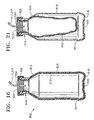
- FIG. 16 is longitudinal, sectional view of the preferred embodiment of the container of the apparatus of FIG. 15.
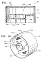
- FIG. 17 is a longitudinal, sectional view of the preferred embodiment of the adapter of the apparatus of FIG. 15 taken along a plane passing through a raised surface of a transverse wall of the adapter.
- FIG. 18 is a rear, right perspective view of the adapter of the apparatus of FIG. 15.
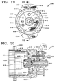
- FIG. 19 is a front view of a preferred embodiment of a receptacle in a surgical console for receiving the apparatus of FIG. 15.
- FIG. 20 is a side, sectional view of the receptacle of FIG. 19 along line 20-20.
- FIG. 21 is a longitudinal, sectional view of the container of the apparatus of FIG. 15 during the.discharge of surgical fluid from the container.
- The preferred embodiments of the present invention and their advantages are best understood by referring to FIGS. 1-21 of the drawings, like numerals being used for like and corresponding parts of the various drawings.
-
Handpiece 10 generally includeshandpiece body 12 andoperative tip 16.Body 12 generally includesexternal irrigation tube 18 and aspiration fitting 20.Body 12 is similar in construction to well-known in the art phacoemulsification handpieces and may be made from plastic, titanium or stainless steel. As best seen in FIG. 6,operative tip 16 includes tip/cap sleeve 26,needle 28 andtube 30.Sleeve 26 may be any suitable commercially available phacoemulsification tip/cap sleeve orsleeve 26 may be incorporated into other tubes as a multi-lumen tube.Needle 28 may be any commercially available hollow phacoemulsification cutting tip, such as the TURBOSONICS tip available from Alcon Laboratories, Inc., Fort Worth, Texas.Tube 30 may be any suitably sized tube to fit withinneedle 28, for example 29 gauge hypodermic needle tubing. - As best seen in FIG. 5,
tube 30 is free on the distal end and connected to pumpingchamber 42 on the proximal end.Tube 30 and pumpingchamber 42 may be sealed fluid tight by any suitable means having a relatively high melting point, such as a silicone gasket, glass frit or silver solder. Fitting 44 holdstube 30 withinbore 48 ofaspiration horn 46.Bore 48 communicates with fitting 20, which is journaled intohorn 46 and sealed with O-ring seal 50 to form an aspiration pathway throughhorn 46 and out fitting 20.Horn 46 is held withinbody 12 by O-ring seal 56 to formirrigation tube 52 which communicates withirrigation tube 18 atport 54. - As best seen in FIG. 7, pumping
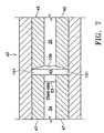
chamber 42 contains a relativelylarge pumping reservoir 43 that is sealed on both ends byelectrodes electrodes reservoir 43 through port 55,tube 34 andcheck valve 53,check valves 53 being well-known in the art. Electrical current (preferably Radio Frequency Alternating Current or RFAC) is delivered to and acrosselectrodes chamber 42 through port 57 and into tube 30 (check valve 53 prevents the expanding fluid from entering tube 34). The expanding gas bubble pushes the surgical fluid intube 30 downstream of pumpingchamber 42 forward. Subsequent pulses of electrical current form sequential gas bubbles that move surgical fluid downtube 30. The size and pressure of the fluid pulse obtained by pumpingchamber 42 can be varied by varying the length, timing and/or power of the electrical pulse sent toelectrodes reservoir 43. In addition, the surgical fluid may be preheated prior to enteringpumping chamber 42. Preheating the surgical fluid will decrease the power required by pumpingchamber 42 and/or increase the speed at which pressure pulses can be generated. - As best seen in FIGS. 8-10,
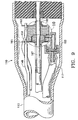
handpiece 110 generally includesbody 112, havingpower supply cable 113, irrigation/aspiration lines 115, and pumpingchamber supply line 117.Distal end 111 ofhandpiece 110 contains pumpingchamber 142 having areservoir 143 formed betweenelectrodes Electrodes body 112 byanodized layer 159 formed onelectrodes Anodized layer 159 is less conductive than untreated aluminum and thus, acts as an electrical insulator.Electrodes electrical terminals Layer 159 may be formed by any suitable anodization technique, well-known in the art, andelectrodes electrical terminals electrodes terminals wires reservoir 143 thoughsupply line 117 andcheck valve 153. Extending distally from pumpingchamber 142 isouter tube 165 that coaxially surroundsaspiration tube 167.Tubes tube 30.Tube 167 is of slightly smaller diameter thantube 165, thereby forming an annular passage orgap 169 betweentube 165 andtube 167.Annular gap 169 fluidly communicates withreservoir 143. - In use, surgical fluid enters
reservoir 143 throughsupply line 117 andcheck valve 153. Electrical current is delivered to and acrosselectrodes chamber 142 throughannular gap 169. The expanding gas bubble pushes forward the surgical fluid inannular gap 169 downstream of pumpingchamber 142. Subsequent pulses of electrical current form sequential gas bubbles that move or propel the surgical fluid downannular gap 169. - One skilled in the art will recognize that the numbering in FIGS. 8-10 is identical to the numbering in FIGS. 1-7 except for the addition of "100" in FIGS. 8-10.
- As best seen in FIGS. 11-13,
handpiece 210 generally includesbody 212, havingpower supply cable 213, irrigation/aspiration lines 215, and pumpingchamber supply line 217.Distal end 211 ofhandpiece 210 contains pumpingchamber 242 having areservoir 243 formed betweenelectrodes Electrodes body 212 byanodized layer 259 formed onelectrodes Anodized layer 259 is less conductive than untreated aluminum and thus, acts as an electrical insulator.Electrodes electrical terminals Layer 259 may be formed by any suitable anodization technique, well-known in the art, andelectrodes electrical terminals electrodes terminals wires reservoir 243 thoughsupply line 217 andcheck valve 253. Extending distally from pumpingchamber 242 isouter tube 265 that coaxially surroundsaspiration tube 267.Tubes tube 30.Tube 267 is of slightly smaller diameter thantube 265, thereby forming an annular passage orgap 269 betweentube 265 andtube 267.Annular gap 269 fluidly communicates withreservoir 243. - In use, surgical fluid enters
reservoir 243 throughsupply line 217 andcheck valve 253. Electrical current is delivered to and acrosselectrodes electrode 247. As the surgical fluid boils, it expands rapidly out of pumpingchamber 242 throughannular gap 269. The expanding gas bubble pushes forward the surgical fluid inannular gap 269 downstream of pumpingchamber 242. Subsequent pulses of electrical current form sequential gas bubbles that move or propel the surgical fluid downannular gap 269. - One skilled in the art will recognize that the numbering in FIGS. 11-13 is identical to the numbering in FIGS. 1-7 except for the addition of "200" in FIGS. 11-13.
- Any handpiece producing adequate pressure pulse force, temperature, rise time and frequency may also be used. For example, any handpiece producing a pressure pulse force of between 0.02 grams and 20.0 grams, with a rise time of between 1 gram/sec and 20,000 grams/sec and a frequency of between 1 Hz and 200 Hz may be used, with between 10 Hz and 100 Hz being most preferred. The pressure pulse force and frequency will vary with the hardness of the material being removed. For example, the inventors have found that a lower frequency with a higher pulse force is most efficient at debulking and removing the relatively hard nuclear material, with a higher frequency and lower pulse force being useful in removing softer epinuclear and cortical material. Infusion pressure, aspiration flow rate and vacuum limit are similar to current phacoemulsification techniques.
- As seen in FIG. 10, one embodiment of
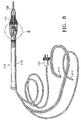
control system 300 for use inoperating handpiece 310 includescontrol module 347, powergain RF amplifier 312 andfunction generator 314. Power is supplied toRF amplifier 312 byDC power supply 316, which preferably is an isolated DC power supply operating at several hundred volts, but typically ±200 volts.Control module 347 may be any suitable microprocessor, micro controller, computer or digital logic controller and may receive input fromoperator input device 318.Function generator 314 provides the electric wave form in kilohertz toamplifier 312 and typically operates at around 450 KHz or above to help minimize corrosion. - In use,
control module 347 receives input fromsurgical console 320.Console 320 may be any commercially available surgical control console such as the LEGACY® SERIES TWENTY THOUSAND® surgical system available from Alcon Laboratories, Inc., Fort Worth, Texas.Console 320 is connected to handpiece 310 throughirrigation line 322 andaspiration line 324, and the flow throughlines footswitch 326. Irrigation and aspiration flow rate information inhandpiece 310 is provided to controlmodule 347 byconsole 320 viainterface 328, which may be connected to the ultrasound handpiece control port onconsole 320 or to any other output port.Control module 347 uses footswitch 326 information provided byconsole 320 and operator input frominput device 318 to generate twocontrol signals Signal 332 is used to operatepinch valve 334, which controls the surgical fluid flowing fromfluid source 336 tohandpiece 310. Fluid fromfluid source 336 is heated in the manner described herein.Signal 330 is used to controlfunction generator 314. Based onsignal 330,function generator 314 provides a wave form at the operator selected frequency and amplitude determined by the position offootswitch 326 toRF amplifier 312 which is amplified to advance the powered wave form output to handpiece 310 to create heated, pressurized pulses of surgical fluid. - Any of a number of methods can be employed to limit the amount of heat introduced into the eye. For example, the pulse train duty cycle of the heated solution can be varied as a function of the pulse frequency so that the total amount of heated solution introduced into the eye does not vary with the pulse frequency. Alternatively, the aspiration flow rate can be varied as a function of pulse frequency so that as pulse frequency increases aspiration flow rate increases proportionally.
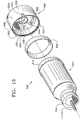
- FIGS. 15-18 show a preferred embodiment of an
apparatus 500 for delivery of a surgical fluid to an ophthalmic surgical handpiece.Apparatus 500 is described herein as delivering a surgical fluid to a liquefracture handpiece such as liquefracture handpieces 10, 110, 210, or 310. However,apparatus 500 may also be used with other surgical handpieces, such as those used in otic or nasal surgery. -
Apparatus 500 preferably includes acontainer 502, anannular gasket 504, and anadapter 506.Container 502 holds the surgical fluid for the liquefracture handpiece and is represented byfluid source 336 in FIG. 14.Adapter 506, in cooperation withgasket 504, forms a fluid tight seal onbottom portion 516 ofcontainer 502 and functions to engageapparatus 500 with a receptacle 508 (FIGS. 19 and 20) ofsurgical console 320. -
Container 502 is preferably a conventional multilayer plastic bottle having a first portion orbody 510 and a second portion ordeformable liner 512 located withinfirst portion 510.Second portion 512 is preferably formed from a deformable plastic that is separable fromfirst portion 510. By way of example,second portion 512 may be formed of nylon. As another example,second portion 512 may be formed of an inner layer of polypropylene coupled to an outer layer of ethylene vinyl oxide with an adhesive therebetween.First portion 510 is preferably formed from a more rigid plastic than used to formsecond portion 512. By way of example,first portion 510 may be formed of high density polyethylene. As another example,first portion 510 may be formed of polypropylene.Container 502 is preferably formed using a conventional extrusion blow molding process. A wide variety of multilayer bottles may be utilized forcontainer 502. An exemplary bottle, and a manufacturing technique therefor, is disclosed in U.S. Patent No. 6,083,450 (Safian). Alternatively,first portion 510 may be formed from stainless steel or other relatively rigid, non-plastic material, andsecond portion 512 may be formed from a deformable material other than plastic. -
First portion 510 generally includes anopen mouth 514, a bottom 516, and aside wall 518.Bottom 516 is formed with anaperture 520. Acircumferential shoulder 521 is preferably formed nearbottom 516.Container 502 preferably also has acap 522 that may be secured tomouth 514.Cap 522 is preferably made of aluminum and is crimp sealed tomouth 514. Alternatively,cap 522 may be secured tomouth 514 by way of threads (not shown).Cap 522 preferably includes arubber stopper 523 having ahole 524 therethrough designed to sealingly receive pumpingchamber supply line mouth 514 offirst portion 510 may be sealed only byrubber stopper 523. -
Adapter 506 generally includes anouter wall 530, a firstopen end 532, a secondopen end 534, and atransverse wall 536.Adapter 506 is preferably made from conventional plastic such as, by way of example, polypropylene. Alternatively,adapter 506 may be formed from stainless steel or other relatively rigid, non-plastic material.Open end 532 receivesgasket 504 andbottom 516 ofcontainer 502. Secondopen end 534 is for engagingreceptacle 508.Outer wall 530 preferably has acircumferential flange 538 on its inside surface that engagesshoulder 521 ofcontainer 502 to secureadapter 506 tocontainer 502.Transverse wall 536 includes anaperture 540 that is preferably disposed in the center ofadapter 506.Transverse wall 536 includes afirst side 542 on the side of firstopen end 532, and asecond side 544 on the side of secondopen end 534.Gasket 504 preferably rests on afirst side 542 oftransverse wall 536 and forms a fluid tight seal withbottom 516.First side 540 also preferably includes a recessedvolume 546.Second side 544 preferably includes anannular skirt 548 and at least one raisedsurface 550. As shown best in FIGS. 15 and 18, raisedsurface 550 preferably has an arc length of about 120 degrees. Thesecond side 544 oftransverse wall 536 creates a pattern that can be used to identify the particular kind of surgical fluid held withincontainer 502, and also whetheradapter 506 is engaged withinreceptacle 508. Although not shown in the FIGS.,second side 544 may be formed with no raisedsurface 550 or with various combinations of multiple raised surfaces 550. For example, two raisedsurfaces 550 may form a continuous raised surface of 240 degrees. As another example, three raisedsurfaces 550 may form a continuous raised surface of 360 degrees. One skilled in the art will recognize that, given the 120 degree arc length of raisedsurface 550 and the possible angular positions aroundaperture 540,second side 544 oftransverse wall 536 may be formed with seven unique patterns of raised surfaces. Each such pattern is representative of a binary signal (e.g. 001, 011, 101, 110, 010, 111, 000) where 1 indicates the presence of a raised surface and 0 indicates the absence of a raised surface. Of course, if a different arc length is used for each raisedsurface 550,second side 544 oftransverse wall 536 may be formed with more or less than seven unique patterns of raised surfaces. Three lugs 552 are disposed on an outer surface ofouter wall 530.Lugs 552 are preferably spaced at 115 degree intervals aroundaperture 540. -
Receptacle 508 generally includes ahousing 602, an interior 604, apiston 606, apiston retainer 608, a pressure spine orneedle 610, and a plurality ofsensors 614.Interior 604 receives secondopen end 534 ofadapter 506. The inner surface ofinterior 604 has threeslots 616 for operative engagement withlugs 552 ofadapter 506. Each ofslots 616 preferably has a "L"-shaped geometry, with one leg of the "L" extending in a clockwise direction along the circumference of the inner surface ofinterior 604 for a distance of less than 90 degrees.Piston 606 has aface seal 618 on a front end thereof, and is biased outwardly from interior 604 by aspring 620 disposed incavity 622.Piston retainer 608 securespiston 606 withininterior 604 and is secured tohousing 602 viabolts 624.Pressure spine 610 has asharp tip 626 and alumen 612 that is fluidly coupled to a source of pressurized fluid (e.g. pressurized air) withinsurgical console 320.Sensors 614 are preferably spaced at 120 degree intervals aroundpressure spine 610 for operative engagement with raisedsurfaces 550 ofadapter 506. Eachsensor 614 preferably includes aplunger 615 that is capable of movement along the longitudinal axis ofhousing 602 and that is biased outwardly by aspring 628 mounted on aspring seat 629; afin 617 coupled toplunger 615, and anoptical sensor 619 mounted on a printedcircuit board 621. An optical path or signal (e.g. beam of light) is formed across the width ofsensor 614 viadual apertures 623 ofoptical sensor 619. An exemplaryoptical sensor 619 suitable forsensor 614 is the EESJ3G interruptive sensor available from Omron Sensors.
Alternatively,sensor 614 may be a conventional force resistive sensor that measures the deflection or deflection force ofplunger 615. Such a force resistive sensor may be formed withoutfin 617,optical sensor 619, and printedcircuit board 621.Receptacle 508 is mounted withinsurgical console 320 via mountingbracket 630. - When a user aligns
lugs 552 withslots 616, slides secondopen end 534 ofadapter 506 intointerior 604, and then twistsadapter 506 in a clockwise direction,adapter 506 is removably secured withinreceptacle 508. At the same time, the inner surface ofannular skirt 548 engages the outer surface ofpiston 606, andpiston 606 moves inwardly throughcavity 622 allowingpressure spine 610 to engageaperture 540 oftransverse wall 536. Recessedvolume 546 preventspressure spine 610 from contactingbottom 516 ofcontainer 502 or piercingsecond portion 512 holding the surgical fluid. At portions ofsecond side 544 oftransverse wall 536 containing raisedsurfaces 550, theplunger 615 of thecorresponding sensor 614 is depressed. If no raisedsurface 550 is present, theplunger 615 of thecorresponding sensor 614 is not depressed, or alternatively is depressed a smaller amount than when a raisedsurface 550 is present. When aplunger 615 of asensor 614 is depressed,fin 617 moves betweendual apertures 623 ofoptical sensor 619 to break the optical path ofsensor 619. Eachsensor 614 having aplunger 615 that is depressed combines to generate a binary, electrical signal representative of a unique pattern of raisedsurfaces 550 onsecond side 544 oftransverse wall 536 that is transmitted tosurgical console 320 via printedcircuit board 621.Control module 347 ofsurgical console 320 may be programmed to associate such electrical signals with a particular surgical fluid having particular properties (e.g. viscosity, surgical fluid supply pressure). In addition,control module 347 may automatically alter or adjust surgical fluid supply pressure, or other operating parameters ofcontrol system 300,surgical console 320, orliquefracture handpiece - Once
apparatus 500 is engaged withinreceptacle 508 as described above, surgical fluid fromcontainer 502 is delivered toliquefracture handpiece 210 in the following preferred manner. Pressurized air is delivered fromlumen 612 ofpressure spine 610, throughaperture 540 ofadapter 506, and throughaperture 520 offirst portion 510 ofcontainer 502. As shown best in FIG. 21, the pressurized air enters the space between the outer surface ofsecond portion 512 and the inner surface offirst portion 510, separatingsecond portion 512 fromfirst portion 510, and at least partially collapsingsecond portion 512. The pressurized air forces the surgical fluid from withinsecond portion 512 tohandpiece 210 viatubing 217. - From the above, it may be appreciated that the present invention provides a simple and reliable apparatus and method of delivering a surgical fluid to a surgical handpiece. The invention further provides an automated way of identifying the particular surgical fluid to be provided to the handpiece.
- The present invention is illustrated herein by example, and various modifications may be made by a person of ordinary skill in the art. For example, second
transverse wall 536 ofcontainer 500, or second side 706 of transverse wall 702 of container 700, may be formed withoutaperture 540. In this case,reference numeral 540 indicates the longitudinal axis ofcontainer 500, andsharp tip 626 ofpressure spine 610 may be formed to pierce secondtransverse wall 536 or transverse wall 702. - It is believed that the operation and construction of the present invention will be apparent from the foregoing description. While the apparatus and methods shown or described above have been characterized as being preferred, various changes and modifications may be made therein without departing from the scope of the invention as defined in the following claims.
Claims (17)
- An apparatus (500) for delivery of a surgical fluid to a surgical handpiece (10, 110, 210, 310) comprising:a container (502) having first (510) and second (512) portions, said second (512) portion made from a deformable material and having a closed end, an open end, an outer surface, and a first volume for receiving a surgical fluid for delivery to a surgical handpiece, said first (510) portion made from a material more rigid than said deformable material and having a first end (514), a second end (516), an outer surface, an inner surface, and a second volume receiving said first portion, said first end (514) having an outlet for delivery of said surgical fluid, said second end (516) having an aperture (520) for receiving a pressurized fluid between said outer surface of said second portion and said inner surface of said first portion; andan adapter (506) having an outer wall (530), a first open end (532), a second open end (534), and a transverse wall (536) coupled to said outer wall (530) and having first (542) and second (544) sides, said first end (532) of said adapter receiving said second end of said first portion, said second side (544) of said transverse wall having an area for removably engaging a source of said pressurized fluid so that said source of said pressurized fluid is in fluid communication with said aperture (520), and
characterised in that said second side (544) of said transverse wall has a geometry providing a binary signal indicative of a particular kind of said surgical fluid. - The apparatus of claim 1 wherein said area of said second side (544) of said transverse wall (536) is capable of being engaged by a lumen (612) for providing said pressurized fluid.
- The apparatus of claim 1 wherein said geometry comprises at least one raised surface (550).
- The apparatus of claim 1 wherein said first side (542) of said transverse wall (536) is sealingly engaged with said second end of said first portion.
- The apparatus of claim 4 further comprising a gasket (504), and wherein said gasket is disposed between said second end (516) of said first portion and said first side of said transverse wall.
- The apparatus of claim 1 wherein said second portion is at least partially separable from said first portion when said surgical fluid is discharged from said first volume.
- The apparatus of claim 1 further comprising:a stopper (523) disposed in said outlet (514) of said first portion (510); andtubing (117, 217) sealingly disposed within said stopper and in fluid communication with said first volume.
- The apparatus of claim 1 wherein said outer wall of said adapter has a plurality of lugs (552) for alignment and operative engagement with a receptacle (508) in a surgical console.
- The apparatus of claim 1 wherein said first side (542) of said transverse wall (536) defines a third volume (546) between said transverse wall and said second end of said first portion, so that said source of said pressurized fluid is in fluid communication with said third volume.
- The apparatus of claim 3 wherein said at least one raised surface (550) has an arc length.
- The apparatus of claim 3 wherein said geometry comprises a pattern of raised surfaces (550).
- The apparatus of claim 11 wherein each of said raised surfaces (550) has an arc length.
- A system for delivering a surgical fluid to a liquefracture handpiece (10, 110, 210, 310), comprising:a liquefracture handpiece having a pumping chamber;an apparatus (500) as claimed in any preceding claim;a surgical console (320) containing said source of said pressurized fluid and having a receptacle (508) for removably receiving said adapter (506), said receptacle having a lumen (612) for fluidly coupling said source of said pressurized fluid with said area of said second side of said transverse wall; andtubing (117, 217) fluidly coupling said outlet of said first portion with said liquefracture handpiece;whereby when said surgical console provides said pressurized fluid from said lumen, said pressurized fluid flows through said aperture (520) and between said outer surface of said second portion and said inner surface of said first portion, and said surgical fluid is delivered to said pumping chamber by said tubing.
- The system of claim 13 wherein said pressurized fluid is air.
- The system of claim 13 wherein said receptacle comprises a plurality of sensors (614) for operatively engaging said geometry for providing a binary signal indicative of a particular kind of said surgical fluid.
- The system of claim 13 wherein said outer wall of said adapter (506) has a plurality of lugs (552) for alignment and operative engagement with a plurality of slots (616) in said receptacle (508).
- The system of claim 16 wherein said lugs and slots cooperate to removably secure said adapter to said receptacle.
Priority Applications (1)
| Application Number | Priority Date | Filing Date | Title |
|---|---|---|---|
| SI200330250T SI1526824T1 (en) | 2002-08-05 | 2003-07-23 | Apparatus for delivery of fluid to ophthalmic surgical handpiece |
Applications Claiming Priority (3)
| Application Number | Priority Date | Filing Date | Title |
|---|---|---|---|
| US212351 | 2002-08-05 | ||
| US10/212,351 US6921385B2 (en) | 2002-08-05 | 2002-08-05 | Apparatus for delivery of fluid to opthalmic surgical handpiece |
| PCT/US2003/023397 WO2004012636A2 (en) | 2002-08-05 | 2003-07-23 | Apparatus for delivery of fluid to ophthalmic surgical handpiece |
Publications (2)
| Publication Number | Publication Date |
|---|---|
| EP1526824A2 EP1526824A2 (en) | 2005-05-04 |
| EP1526824B1 true EP1526824B1 (en) | 2006-02-15 |
Family
ID=31187752
Family Applications (1)
| Application Number | Title | Priority Date | Filing Date |
|---|---|---|---|
| EP03766923A Expired - Lifetime EP1526824B1 (en) | 2002-08-05 | 2003-07-23 | Apparatus for delivery of fluid to ophthalmic surgical handpiece |
Country Status (16)
| Country | Link |
|---|---|
| US (1) | US6921385B2 (en) |
| EP (1) | EP1526824B1 (en) |
| JP (1) | JP4394571B2 (en) |
| AR (1) | AR040735A1 (en) |
| AT (1) | ATE317678T1 (en) |
| BR (1) | BR0313144A (en) |
| CA (1) | CA2490829C (en) |
| CY (1) | CY1105030T1 (en) |
| DE (1) | DE60303609T2 (en) |
| DK (1) | DK1526824T3 (en) |
| ES (1) | ES2256782T3 (en) |
| IL (1) | IL166333A (en) |
| MX (1) | MXPA05000606A (en) |
| PT (1) | PT1526824E (en) |
| SI (1) | SI1526824T1 (en) |
| WO (1) | WO2004012636A2 (en) |
Cited By (3)
| Publication number | Priority date | Publication date | Assignee | Title |
|---|---|---|---|---|
| US8377001B2 (en) | 2010-10-01 | 2013-02-19 | Abbott Laboratories | Feeding set for a peristaltic pump system |
| US8377000B2 (en) | 2010-10-01 | 2013-02-19 | Abbott Laboratories | Enteral feeding apparatus having a feeding set |
| US8689439B2 (en) | 2010-08-06 | 2014-04-08 | Abbott Laboratories | Method for forming a tube for use with a pump delivery system |
Families Citing this family (58)
| Publication number | Priority date | Publication date | Assignee | Title |
|---|---|---|---|---|
| US7892229B2 (en) | 2003-01-18 | 2011-02-22 | Tsunami Medtech, Llc | Medical instruments and techniques for treating pulmonary disorders |
| US8016823B2 (en) | 2003-01-18 | 2011-09-13 | Tsunami Medtech, Llc | Medical instrument and method of use |
| US7549987B2 (en) | 2000-12-09 | 2009-06-23 | Tsunami Medtech, Llc | Thermotherapy device |
| US9433457B2 (en) | 2000-12-09 | 2016-09-06 | Tsunami Medtech, Llc | Medical instruments and techniques for thermally-mediated therapies |
| US8444636B2 (en) | 2001-12-07 | 2013-05-21 | Tsunami Medtech, Llc | Medical instrument and method of use |
| AU2003303928A1 (en) * | 2003-02-14 | 2004-09-09 | Alcon, Inc. | Apparatus and method for determining that a surgical fluid container is near empty |
| WO2004073751A2 (en) * | 2003-02-14 | 2004-09-02 | Alcon, Inc. | Apparatus and method for determining that a surgical fluid container is near empty |
| US20060161101A1 (en) * | 2005-01-18 | 2006-07-20 | Alcon, Inc. | Surgical system and handpiece |
| US7758585B2 (en) * | 2005-03-16 | 2010-07-20 | Alcon, Inc. | Pumping chamber for a liquefaction handpiece |
| US20060212037A1 (en) * | 2005-03-16 | 2006-09-21 | Alcon, Inc. | Pumping chamber for a liquefaction handpiece |
| US20070032785A1 (en) | 2005-08-03 | 2007-02-08 | Jennifer Diederich | Tissue evacuation device |
| KR20090067218A (en) * | 2006-10-16 | 2009-06-24 | 알콘 리서치, 리미티드 | Method of operating ophthalmic hand piece with disposable end |
| US20080154282A1 (en) * | 2006-12-20 | 2008-06-26 | Stacy Faught | Fluidic Coupling For Surgical Hand Piece |
| US7540855B2 (en) * | 2007-06-01 | 2009-06-02 | Peregrine Surgical, Ltd. | Disposable aspirator cassette |
| WO2009009398A1 (en) | 2007-07-06 | 2009-01-15 | Tsunami Medtech, Llc | Medical system and method of use |
| US7849875B2 (en) * | 2007-07-31 | 2010-12-14 | Alcon, Inc. | Check valve |
| US20090032121A1 (en) * | 2007-07-31 | 2009-02-05 | Chon James Y | Check Valve |
| EP2198797B1 (en) | 2007-08-23 | 2011-04-13 | Aegea Medical, Inc. | Uterine therapy device |
| JP2011505919A (en) * | 2007-12-07 | 2011-03-03 | ゼヴェクス・インコーポレーテッド | Method for inducing lateral motion in Langevin type vibrators using split electrodes of ceramic elements |
| US9924992B2 (en) | 2008-02-20 | 2018-03-27 | Tsunami Medtech, Llc | Medical system and method of use |
| US8721632B2 (en) | 2008-09-09 | 2014-05-13 | Tsunami Medtech, Llc | Methods for delivering energy into a target tissue of a body |
| US8579888B2 (en) | 2008-06-17 | 2013-11-12 | Tsunami Medtech, Llc | Medical probes for the treatment of blood vessels |
| US8454551B2 (en) * | 2008-08-22 | 2013-06-04 | Zevex, Inc. | Removable adapter for phacoemulsification handpiece having irrigation and aspiration fluid paths |
| US8291933B2 (en) | 2008-09-25 | 2012-10-23 | Novartis Ag | Spring-less check valve for a handpiece |
| US10695126B2 (en) | 2008-10-06 | 2020-06-30 | Santa Anna Tech Llc | Catheter with a double balloon structure to generate and apply a heated ablative zone to tissue |
| US9561066B2 (en) | 2008-10-06 | 2017-02-07 | Virender K. Sharma | Method and apparatus for tissue ablation |
| EP2341859B1 (en) | 2008-10-06 | 2017-04-05 | Virender K. Sharma | Apparatus for tissue ablation |
| US9561068B2 (en) | 2008-10-06 | 2017-02-07 | Virender K. Sharma | Method and apparatus for tissue ablation |
| US10064697B2 (en) | 2008-10-06 | 2018-09-04 | Santa Anna Tech Llc | Vapor based ablation system for treating various indications |
| US9561067B2 (en) | 2008-10-06 | 2017-02-07 | Virender K. Sharma | Method and apparatus for tissue ablation |
| US8545554B2 (en) * | 2009-01-16 | 2013-10-01 | Allergan, Inc. | Intraocular injector |
| US11284931B2 (en) | 2009-02-03 | 2022-03-29 | Tsunami Medtech, Llc | Medical systems and methods for ablating and absorbing tissue |
| US8900223B2 (en) | 2009-11-06 | 2014-12-02 | Tsunami Medtech, Llc | Tissue ablation systems and methods of use |
| US8568396B2 (en) | 2009-12-10 | 2013-10-29 | Alcon Research, Ltd. | Flooded liquefaction hand piece engine |
| US9161801B2 (en) | 2009-12-30 | 2015-10-20 | Tsunami Medtech, Llc | Medical system and method of use |
| US7833206B1 (en) | 2010-02-02 | 2010-11-16 | Peregrine Surgical, Ltd. | Method and apparatus for disposable aspirator cassette |
| US9943353B2 (en) | 2013-03-15 | 2018-04-17 | Tsunami Medtech, Llc | Medical system and method of use |
| US9743974B2 (en) | 2010-11-09 | 2017-08-29 | Aegea Medical Inc. | Positioning method and apparatus for delivering vapor to the uterus |
| AU2011341430B2 (en) * | 2010-12-15 | 2016-06-30 | Alcon Inc. | Infusion sleeve with multiple material layers |
| JP6017568B2 (en) | 2011-10-07 | 2016-11-02 | イージー メディカル, インコーポレーテッド | Uterine treatment device |
| US8852091B2 (en) | 2012-04-04 | 2014-10-07 | Alcon Research, Ltd. | Devices, systems, and methods for pupil expansion |
| GB2519711B (en) * | 2012-08-28 | 2016-07-06 | Univ Colorado Regents | Ophthalmic surgical device with adjustable filament |
| US9480782B2 (en) * | 2013-01-14 | 2016-11-01 | R. Ashley Burrow | Surgical aspiration and irrigation |
| US20140228875A1 (en) | 2013-02-08 | 2014-08-14 | Nidus Medical, Llc | Surgical device with integrated visualization and cauterization |
| US20150031946A1 (en) | 2013-07-24 | 2015-01-29 | Nidus Medical, Llc | Direct vision cryosurgical probe and methods of use |
| US9687288B2 (en) | 2013-09-30 | 2017-06-27 | Arrinex, Inc. | Apparatus and methods for treating rhinitis |
| WO2015179662A1 (en) | 2014-05-22 | 2015-11-26 | Aegea Medical Inc. | Integrity testing method and apparatus for delivering vapor to the uterus |
| CN106794030B (en) | 2014-05-22 | 2019-09-03 | 埃杰亚医疗公司 | System and method for executing endometrial ablation |
| US9763743B2 (en) | 2014-07-25 | 2017-09-19 | Arrinex, Inc. | Apparatus and method for treating rhinitis |
| RU2603718C2 (en) * | 2015-04-17 | 2016-11-27 | ЗАКРЫТОЕ АКЦИОНЕРНОЕ ОБЩЕСТВО "ОПТИМЕДСЕРВИС" (ЗАО "Оптимедсервис") | Ultrasonic instrument of phacoemulsifier with three-dimensional vibrations |
| EP3413822B1 (en) | 2016-02-11 | 2023-08-30 | Arrinex, Inc. | Device for image guided post-nasal nerve ablation |
| ES2929383T3 (en) | 2016-02-19 | 2022-11-28 | Aegea Medical Inc | Methods and apparatus for determining the integrity of a body cavity |
| US11331140B2 (en) | 2016-05-19 | 2022-05-17 | Aqua Heart, Inc. | Heated vapor ablation systems and methods for treating cardiac conditions |
| EP3471638A4 (en) | 2016-06-15 | 2020-03-11 | Arrinex, Inc. | Devices and methods for treating a lateral surface of a nasal cavity |
| US11253312B2 (en) | 2016-10-17 | 2022-02-22 | Arrinex, Inc. | Integrated nasal nerve detector ablation-apparatus, nasal nerve locator, and methods of use |
| JP7300999B2 (en) | 2017-04-28 | 2023-06-30 | アリネックス, インコーポレイテッド | Systems and methods for locating blood vessels in the treatment of rhinitis |
| AU2019279011A1 (en) | 2018-06-01 | 2021-01-07 | Santa Anna Tech Llc | Multi-stage vapor-based ablation treatment methods and vapor generation and delivery systems |
| AU2020307328A1 (en) * | 2019-06-27 | 2021-12-09 | Alcon Inc. | IOL base compression device having an IOL towing mechanism |
Family Cites Families (66)
| Publication number | Priority date | Publication date | Assignee | Title |
|---|---|---|---|---|
| US2678764A (en) | 1951-12-06 | 1954-05-18 | Emery Carpenter Container Comp | Accessory for use in filling lined containers |
| US2766907A (en) | 1955-03-15 | 1956-10-16 | Robbins Instr Corp | Pressure infusion apparatus |
| CH461034A (en) * | 1966-06-27 | 1968-08-15 | Werding Wienfried | Transfusion device |
| NL145136C (en) | 1967-07-25 | 1900-01-01 | ||
| US3595232A (en) | 1968-08-19 | 1971-07-27 | Saul Leibinsohn | Nongravitational infusion assembly |
| US3780732A (en) | 1968-08-19 | 1973-12-25 | S Leibinsoh | Non-gravitational infusion set |
| US3690318A (en) * | 1970-04-16 | 1972-09-12 | Bourns Inc | Apparatus for parenteral fluid infusion provided with variable flow control means |
| US3838794A (en) | 1972-07-10 | 1974-10-01 | H Markham | Package for storing and dispensing liquids |
| US3940001A (en) | 1972-10-06 | 1976-02-24 | Ethyl Corporation | Recyclable plastic containers |
| US3949753A (en) | 1972-11-27 | 1976-04-13 | Rolf Dockhorn | Apparatus for supplying aseptic fluids |
| US4008830A (en) | 1973-08-10 | 1977-02-22 | Philip Meshberg | Liquid dispenser using a non vented pump and a collapsible plastic bag |
| US4090514A (en) | 1976-10-22 | 1978-05-23 | Howard Helmut Hinck | Pressure infusion device |
| US4270533A (en) | 1977-08-16 | 1981-06-02 | Andreas Joseph M | Multiple chamber container for delivering liquid under pressure |
| US4223676A (en) | 1977-12-19 | 1980-09-23 | Cavitron Corporation | Ultrasonic aspirator |
| US4246902A (en) | 1978-03-10 | 1981-01-27 | Miguel Martinez | Surgical cutting instrument |
| US4379453A (en) | 1978-12-28 | 1983-04-12 | Baron Howard C | Infusion system with self-generating pressure assembly |
| US4301802A (en) | 1980-03-17 | 1981-11-24 | Stanley Poler | Cauterizing tool for ophthalmological surgery |
| US4337769A (en) | 1980-08-01 | 1982-07-06 | Baxter Travenol Laboratories, Inc. | Pressure infusion module |
| US4493694A (en) | 1980-10-17 | 1985-01-15 | Cooper Lasersonics, Inc. | Surgical pre-aspirator |
| US4330066A (en) | 1980-11-21 | 1982-05-18 | Robert Berliner | Receptacle with collapsible internal container |
| US4396382A (en) | 1981-12-07 | 1983-08-02 | Travenol European Research And Development Centre | Multiple chamber system for peritoneal dialysis |
| US4507116A (en) | 1982-04-22 | 1985-03-26 | Saul Leibinsohn | Apparatus for the induced infusion of a liquid from a flexible liquid bag |
| US4515583A (en) | 1983-10-17 | 1985-05-07 | Coopervision, Inc. | Operative elliptical probe for ultrasonic surgical instrument and method of its use |
| US4609368A (en) | 1984-08-22 | 1986-09-02 | Dotson Robert S Jun | Pneumatic ultrasonic surgical handpiece |
| US4589415A (en) | 1984-08-31 | 1986-05-20 | Haaga John R | Method and system for fragmenting kidney stones |
| DE3442092A1 (en) | 1984-11-17 | 1986-05-28 | Kautex Werke Reinold Hagen AG, 5300 Bonn | METHOD FOR PRODUCING A PACKAGING PROVIDED WITH A LOCKABLE OPENING AND PACKAGING PRODUCED BY THIS METHOD |
| US4626243A (en) | 1985-06-21 | 1986-12-02 | Applied Biomedical Corporation | Gravity-independent infusion system |
| US4922902A (en) | 1986-05-19 | 1990-05-08 | Valleylab, Inc. | Method for removing cellular material with endoscopic ultrasonic aspirator |
| US5312018A (en) | 1988-07-08 | 1994-05-17 | Evezich Paul D | Containing and dispensing device for flowable material having relatively rigid and deformable material containment portions |
| JPH01198539A (en) * | 1987-10-26 | 1989-08-10 | Marui Ika:Kk | Water jet knife apparatus for cerebral surgery use |
| US4892230A (en) | 1988-02-08 | 1990-01-09 | Lynn Jr Arthur E | Carbonated beverage bottle |
| US4821896A (en) | 1988-03-24 | 1989-04-18 | Cheng Ping N | Nursing bottle with a liner and vent |
| US4869715A (en) | 1988-04-21 | 1989-09-26 | Sherburne Fred S | Ultrasonic cone and method of construction |
| US4976707A (en) | 1988-05-04 | 1990-12-11 | Sherwood Medical Company | Fluid collection, storage and infusion apparatus |
| US5060826A (en) | 1988-08-25 | 1991-10-29 | Fabricated Metals, Inc. | Container with inflatable vessel for controlling flow of liquid or viscous material |
| US4989583A (en) | 1988-10-21 | 1991-02-05 | Nestle S.A. | Ultrasonic cutting tip assembly |
| US5013303A (en) | 1988-11-03 | 1991-05-07 | Yehuda Tamari | Constant pressure infusion device |
| US5154694A (en) | 1989-06-06 | 1992-10-13 | Kelman Charles D | Tissue scraper device for medical use |
| US5207638A (en) | 1989-08-24 | 1993-05-04 | Hemotrans, Inc. | Blood transfer apparatus |
| CA2048120A1 (en) * | 1990-08-06 | 1992-02-07 | William J. Drasler | Thrombectomy method and device |
| US5163909A (en) * | 1991-01-28 | 1992-11-17 | Alan E. Jordan | Medical fluid delivery system |
| AU666324B2 (en) | 1991-08-05 | 1996-02-08 | Yoshino Kogyosho Co., Ltd. | Bottle of laminate structure and method of making said bottle |
| KR100297118B1 (en) | 1992-05-11 | 2001-11-22 | 요시노 쇼이치로 | Laminated Bottle and Laminated Bottle Pump |
| US5738657A (en) | 1992-06-15 | 1998-04-14 | Abbott Laboratories | Ambulatory energized container system |
| JP2680510B2 (en) | 1992-06-26 | 1997-11-19 | シャープ株式会社 | Cassette size detection mechanism |
| US5620414A (en) * | 1992-06-30 | 1997-04-15 | Campbell, Jr.; Robert M. | Apparatus and method for effecting surgical incision through use of a fluid jet |
| DE4332885A1 (en) | 1992-09-28 | 1994-03-31 | Colgate Palmolive Co | Squeezable dispenser for toothpaste etc. - has inner flexible disposable container fitting into outer container and closed by cap and one-way locking valves |
| GB9227195D0 (en) | 1992-12-16 | 1993-03-03 | Prior Francis G R | Bag |
| US5403276A (en) | 1993-02-16 | 1995-04-04 | Danek Medical, Inc. | Apparatus for minimally invasive tissue removal |
| US5431627A (en) | 1993-11-12 | 1995-07-11 | Abbott Laboratories | Cassette identification system for use with a multi-program drug infusion pump |
| US5531697A (en) | 1994-04-15 | 1996-07-02 | Sims Deltec, Inc. | Systems and methods for cassette identification for drug pumps |
| US5505708A (en) | 1994-04-18 | 1996-04-09 | Atkinson; Carey J. | System for delivery of intravenous fluids and the like and the method of making thereof |
| US5497912A (en) | 1994-10-20 | 1996-03-12 | Hoback; Michael W. | Disposable self-dispensing pressurized package for delivery of sterile fluids |
| US5810202A (en) | 1994-10-20 | 1998-09-22 | Rick R. Wascher, P.C. | Disposable self-dispensing pressurized package for delivery of sterile fluids and solutions |
| US5616120A (en) | 1995-02-06 | 1997-04-01 | Andrew; Mark S. | Method and apparatus for lenticular liquefaction and aspiration |
| CH691219A5 (en) | 1995-10-26 | 2001-05-31 | Medtronic Electromedics Inc | Disposable filtration flexible bag. |
| US5899674A (en) | 1995-12-01 | 1999-05-04 | Alcon Laboratories, Inc. | Indentification system for a surgical cassette |
| US6059544A (en) | 1995-12-01 | 2000-05-09 | Alcon Laboratories, Inc. | Identification system for a surgical cassette |
| AUPO178796A0 (en) | 1996-08-22 | 1996-09-12 | Oversby Pty Ltd | Intraocular irrigation/aspiration device |
| US5885243A (en) | 1996-12-11 | 1999-03-23 | Alcon Laboratories, Inc. | Liquefaction handpiece |
| CA2230768C (en) | 1997-02-28 | 2007-02-13 | John W. Safian | Multilayer container package |
| US6036458A (en) | 1997-10-03 | 2000-03-14 | Allergan Sales, Inc. | Automated phaco pack bar code reader identification |
| IL123839A0 (en) | 1998-03-26 | 1998-10-30 | Atad Dev & Medical Services Ltd | Pressurized intravenous infusion bag |
| US6206848B1 (en) | 1998-06-04 | 2001-03-27 | Alcon Laboratories, Inc. | Liquefracture handpiece |
| US6276567B1 (en) * | 1999-03-29 | 2001-08-21 | Hydrus, Inc. | Pressurized fluid delivery apparatus |
| US6363932B1 (en) | 2000-07-06 | 2002-04-02 | Clinical Technologies, Inc. | Aerosol enhancement device |
-
2002
- 2002-08-05 US US10/212,351 patent/US6921385B2/en not_active Expired - Lifetime
-
2003
- 2003-07-23 BR BRPI0313144-0A patent/BR0313144A/en not_active IP Right Cessation
- 2003-07-23 PT PT03766923T patent/PT1526824E/en unknown
- 2003-07-23 DE DE60303609T patent/DE60303609T2/en not_active Expired - Lifetime
- 2003-07-23 ES ES03766923T patent/ES2256782T3/en not_active Expired - Lifetime
- 2003-07-23 MX MXPA05000606A patent/MXPA05000606A/en active IP Right Grant
- 2003-07-23 WO PCT/US2003/023397 patent/WO2004012636A2/en active IP Right Grant
- 2003-07-23 DK DK03766923T patent/DK1526824T3/en active
- 2003-07-23 EP EP03766923A patent/EP1526824B1/en not_active Expired - Lifetime
- 2003-07-23 AT AT03766923T patent/ATE317678T1/en active
- 2003-07-23 SI SI200330250T patent/SI1526824T1/en unknown
- 2003-07-23 CA CA2490829A patent/CA2490829C/en not_active Expired - Fee Related
- 2003-07-23 JP JP2004526168A patent/JP4394571B2/en not_active Expired - Lifetime
- 2003-07-30 AR AR20030102738A patent/AR040735A1/en unknown
-
2005
- 2005-01-17 IL IL166333A patent/IL166333A/en not_active IP Right Cessation
-
2006
- 2006-05-11 CY CY20061100609T patent/CY1105030T1/en unknown
Cited By (3)
| Publication number | Priority date | Publication date | Assignee | Title |
|---|---|---|---|---|
| US8689439B2 (en) | 2010-08-06 | 2014-04-08 | Abbott Laboratories | Method for forming a tube for use with a pump delivery system |
| US8377001B2 (en) | 2010-10-01 | 2013-02-19 | Abbott Laboratories | Feeding set for a peristaltic pump system |
| US8377000B2 (en) | 2010-10-01 | 2013-02-19 | Abbott Laboratories | Enteral feeding apparatus having a feeding set |
Also Published As
| Publication number | Publication date |
|---|---|
| IL166333A (en) | 2009-02-11 |
| SI1526824T1 (en) | 2006-08-31 |
| WO2004012636A3 (en) | 2004-06-10 |
| AR040735A1 (en) | 2005-04-20 |
| BR0313144A (en) | 2007-07-17 |
| DE60303609T2 (en) | 2006-09-21 |
| DK1526824T3 (en) | 2006-06-19 |
| CY1105030T1 (en) | 2009-11-04 |
| US20040024412A1 (en) | 2004-02-05 |
| IL166333A0 (en) | 2006-01-16 |
| ATE317678T1 (en) | 2006-03-15 |
| AU2003254195A1 (en) | 2004-02-23 |
| DE60303609D1 (en) | 2006-04-20 |
| CA2490829C (en) | 2011-01-25 |
| ES2256782T3 (en) | 2006-07-16 |
| WO2004012636A2 (en) | 2004-02-12 |
| PT1526824E (en) | 2006-06-30 |
| JP4394571B2 (en) | 2010-01-06 |
| MXPA05000606A (en) | 2005-03-31 |
| JP2005534413A (en) | 2005-11-17 |
| US6921385B2 (en) | 2005-07-26 |
| EP1526824A2 (en) | 2005-05-04 |
| CA2490829A1 (en) | 2004-02-12 |
Similar Documents
| Publication | Publication Date | Title |
|---|---|---|
| EP1526824B1 (en) | Apparatus for delivery of fluid to ophthalmic surgical handpiece | |
| US7695447B2 (en) | Apparatus and method for determining that a surgical fluid container is near empty | |
| US20050228423A1 (en) | Apparatus and method for determining that a surgical fluid container is near empty | |
| AU769048B2 (en) | Tip for a liquefracture handpiece | |
| EP1553902B1 (en) | Container for delivery of fluid to ophthalmic surgical handpiece | |
| EP1199054B1 (en) | Liquefracture handpiece | |
| CA2382533C (en) | Liquefracture handpiece | |
| WO2001030283A1 (en) | Liquefracture handpiece tip | |
| AU2003254195B2 (en) | Apparatus for delivery of fluid to ophthalmic surgical handpiece |
Legal Events
| Date | Code | Title | Description |
|---|---|---|---|
| PUAI | Public reference made under article 153(3) epc to a published international application that has entered the european phase |
Free format text: ORIGINAL CODE: 0009012 |
|
| 17P | Request for examination filed |
Effective date: 20050113 |
|
| AK | Designated contracting states |
Kind code of ref document: A2 Designated state(s): AT BE BG CH CY CZ DE DK EE ES FI FR GB GR HU IE IT LI LU MC NL PT RO SE SI SK TR |
|
| 17Q | First examination report despatched |
Effective date: 20050513 |
|
| GRAP | Despatch of communication of intention to grant a patent |
Free format text: ORIGINAL CODE: EPIDOSNIGR1 |
|
| GRAS | Grant fee paid |
Free format text: ORIGINAL CODE: EPIDOSNIGR3 |
|
| GRAA | (expected) grant |
Free format text: ORIGINAL CODE: 0009210 |
|
| AK | Designated contracting states |
Kind code of ref document: B1 Designated state(s): AT BE BG CH CY CZ DE DK EE ES FI FR GB GR HU IE IT LI LU MC NL PT RO SE SI SK TR |
|
| REG | Reference to a national code |
Ref country code: GB Ref legal event code: FG4D Ref country code: CH Ref legal event code: EP |
|
| REG | Reference to a national code |
Ref country code: IE Ref legal event code: FG4D |
|
| REF | Corresponds to: |
Ref document number: 60303609 Country of ref document: DE Date of ref document: 20060420 Kind code of ref document: P |
|
| REG | Reference to a national code |
Ref country code: RO Ref legal event code: EPE |
|
| REG | Reference to a national code |
Ref country code: SE Ref legal event code: TRGR |
|
| REG | Reference to a national code |
Ref country code: EE Ref legal event code: FG4A Ref document number: E000311 Country of ref document: EE Effective date: 20060421 |
|
| REG | Reference to a national code |
Ref country code: DK Ref legal event code: T3 |
|
| REG | Reference to a national code |
Ref country code: PT Ref legal event code: SC4A Effective date: 20060504 Ref country code: GR Ref legal event code: EP Ref document number: 20060401575 Country of ref document: GR |
|
| REG | Reference to a national code |
Ref country code: ES Ref legal event code: FG2A Ref document number: 2256782 Country of ref document: ES Kind code of ref document: T3 |
|
| REG | Reference to a national code |
Ref country code: HU Ref legal event code: AG4A Ref document number: E000402 Country of ref document: HU |
|
| ET | Fr: translation filed | ||
| PLBE | No opposition filed within time limit |
Free format text: ORIGINAL CODE: 0009261 |
|
| STAA | Information on the status of an ep patent application or granted ep patent |
Free format text: STATUS: NO OPPOSITION FILED WITHIN TIME LIMIT |
|
| 26N | No opposition filed |
Effective date: 20061116 |
|
| PGFP | Annual fee paid to national office [announced via postgrant information from national office to epo] |
Ref country code: CY Payment date: 20100713 Year of fee payment: 8 |
|
| PGFP | Annual fee paid to national office [announced via postgrant information from national office to epo] |
Ref country code: LU Payment date: 20110801 Year of fee payment: 9 |
|
| PGFP | Annual fee paid to national office [announced via postgrant information from national office to epo] |
Ref country code: MC Payment date: 20110704 Year of fee payment: 9 Ref country code: IE Payment date: 20110725 Year of fee payment: 9 Ref country code: DK Payment date: 20110725 Year of fee payment: 9 |
|
| PGFP | Annual fee paid to national office [announced via postgrant information from national office to epo] |
Ref country code: AT Payment date: 20110705 Year of fee payment: 9 Ref country code: CZ Payment date: 20110714 Year of fee payment: 9 Ref country code: GR Payment date: 20110726 Year of fee payment: 9 Ref country code: TR Payment date: 20110711 Year of fee payment: 9 Ref country code: SK Payment date: 20110706 Year of fee payment: 9 Ref country code: SI Payment date: 20110712 Year of fee payment: 9 Ref country code: SE Payment date: 20110727 Year of fee payment: 9 Ref country code: RO Payment date: 20110711 Year of fee payment: 9 Ref country code: PT Payment date: 20110706 Year of fee payment: 9 Ref country code: HU Payment date: 20110712 Year of fee payment: 9 Ref country code: EE Payment date: 20110705 Year of fee payment: 9 Ref country code: FI Payment date: 20110727 Year of fee payment: 9 |
|
| PGFP | Annual fee paid to national office [announced via postgrant information from national office to epo] |
Ref country code: BE Payment date: 20110728 Year of fee payment: 9 |
|
| REG | Reference to a national code |
Ref country code: PT Ref legal event code: MM4A Free format text: LAPSE DUE TO NON-PAYMENT OF FEES Effective date: 20130123 |
|
| BERE | Be: lapsed |
Owner name: *ALCON INC. Effective date: 20120731 |
|
| PG25 | Lapsed in a contracting state [announced via postgrant information from national office to epo] |
Ref country code: MC Free format text: LAPSE BECAUSE OF NON-PAYMENT OF DUE FEES Effective date: 20120731 |
|
| REG | Reference to a national code |
Ref country code: GR Ref legal event code: ML Ref document number: 20060401575 Country of ref document: GR Effective date: 20130104 |
|
| REG | Reference to a national code |
Ref country code: SE Ref legal event code: EUG |
|
| REG | Reference to a national code |
Ref country code: AT Ref legal event code: MM01 Ref document number: 317678 Country of ref document: AT Kind code of ref document: T Effective date: 20120723 |
|
| REG | Reference to a national code |
Ref country code: DK Ref legal event code: EBP |
|
| REG | Reference to a national code |
Ref country code: SK Ref legal event code: MM4A Ref document number: E 669 Country of ref document: SK Effective date: 20120723 |
|
| REG | Reference to a national code |
Ref country code: EE Ref legal event code: MM4A Ref document number: E000311 Country of ref document: EE Effective date: 20120731 |
|
| PG25 | Lapsed in a contracting state [announced via postgrant information from national office to epo] |
Ref country code: FI Free format text: LAPSE BECAUSE OF NON-PAYMENT OF DUE FEES Effective date: 20120723 Ref country code: SE Free format text: LAPSE BECAUSE OF NON-PAYMENT OF DUE FEES Effective date: 20120724 Ref country code: HU Free format text: LAPSE BECAUSE OF NON-PAYMENT OF DUE FEES Effective date: 20120724 Ref country code: EE Free format text: LAPSE BECAUSE OF NON-PAYMENT OF DUE FEES Effective date: 20120731 Ref country code: CZ Free format text: LAPSE BECAUSE OF NON-PAYMENT OF DUE FEES Effective date: 20120723 |
|
| REG | Reference to a national code |
Ref country code: SI Ref legal event code: KO00 Effective date: 20130304 |
|
| REG | Reference to a national code |
Ref country code: IE Ref legal event code: MM4A |
|
| PG25 | Lapsed in a contracting state [announced via postgrant information from national office to epo] |
Ref country code: BE Free format text: LAPSE BECAUSE OF NON-PAYMENT OF DUE FEES Effective date: 20120731 Ref country code: SI Free format text: LAPSE BECAUSE OF NON-PAYMENT OF DUE FEES Effective date: 20120724 Ref country code: PT Free format text: LAPSE BECAUSE OF NON-PAYMENT OF DUE FEES Effective date: 20130123 Ref country code: GR Free format text: LAPSE BECAUSE OF NON-PAYMENT OF DUE FEES Effective date: 20130204 Ref country code: SK Free format text: LAPSE BECAUSE OF NON-PAYMENT OF DUE FEES Effective date: 20120723 Ref country code: CY Free format text: LAPSE BECAUSE OF NON-PAYMENT OF DUE FEES Effective date: 20120723 |
|
| PG25 | Lapsed in a contracting state [announced via postgrant information from national office to epo] |
Ref country code: AT Free format text: LAPSE BECAUSE OF NON-PAYMENT OF DUE FEES Effective date: 20120723 |
|
| PG25 | Lapsed in a contracting state [announced via postgrant information from national office to epo] |
Ref country code: IE Free format text: LAPSE BECAUSE OF NON-PAYMENT OF DUE FEES Effective date: 20120723 Ref country code: DK Free format text: LAPSE BECAUSE OF NON-PAYMENT OF DUE FEES Effective date: 20120731 |
|
| PG25 | Lapsed in a contracting state [announced via postgrant information from national office to epo] |
Ref country code: RO Free format text: LAPSE BECAUSE OF NON-PAYMENT OF DUE FEES Effective date: 20120723 |
|
| PG25 | Lapsed in a contracting state [announced via postgrant information from national office to epo] |
Ref country code: TR Free format text: LAPSE BECAUSE OF NON-PAYMENT OF DUE FEES Effective date: 20120723 |
|
| PG25 | Lapsed in a contracting state [announced via postgrant information from national office to epo] |
Ref country code: LU Free format text: LAPSE BECAUSE OF NON-PAYMENT OF DUE FEES Effective date: 20120723 |
|
| PG25 | Lapsed in a contracting state [announced via postgrant information from national office to epo] |
Ref country code: BG Free format text: LAPSE BECAUSE OF NON-PAYMENT OF DUE FEES Effective date: 20120731 |
|
| REG | Reference to a national code |
Ref country code: FR Ref legal event code: PLFP Year of fee payment: 14 |
|
| REG | Reference to a national code |
Ref country code: FR Ref legal event code: PLFP Year of fee payment: 15 |
|
| REG | Reference to a national code |
Ref country code: FR Ref legal event code: PLFP Year of fee payment: 16 |
|
| PGFP | Annual fee paid to national office [announced via postgrant information from national office to epo] |
Ref country code: BG Payment date: 20190521 Year of fee payment: 17 |
|
| PGFP | Annual fee paid to national office [announced via postgrant information from national office to epo] |
Ref country code: IT Payment date: 20190719 Year of fee payment: 17 Ref country code: ES Payment date: 20190801 Year of fee payment: 17 |
|
| REG | Reference to a national code |
Ref country code: NL Ref legal event code: PD Owner name: ALCON INC.; CH Free format text: DETAILS ASSIGNMENT: CHANGE OF OWNER(S), MERGE; FORMER OWNER NAME: NOVARTIS AG Effective date: 20191031 |
|
| REG | Reference to a national code |
Ref country code: CH Ref legal event code: PUE Owner name: ALCON INC., CH Free format text: FORMER OWNER: ALCON, INC., CH |
|
| PGFP | Annual fee paid to national office [announced via postgrant information from national office to epo] |
Ref country code: CH Payment date: 20190718 Year of fee payment: 17 |
|
| REG | Reference to a national code |
Ref country code: GB Ref legal event code: 732E Free format text: REGISTERED BETWEEN 20200109 AND 20200115 |
|
| REG | Reference to a national code |
Ref country code: GB Ref legal event code: 732E Free format text: REGISTERED BETWEEN 20200116 AND 20200122 |
|
| REG | Reference to a national code |
Ref country code: DE Ref legal event code: R082 Ref document number: 60303609 Country of ref document: DE Representative=s name: BOEHMERT & BOEHMERT ANWALTSPARTNERSCHAFT MBB -, DE Ref country code: DE Ref legal event code: R081 Ref document number: 60303609 Country of ref document: DE Owner name: ALCON INC., CH Free format text: FORMER OWNER: ALCON INC., HUENENBERG, CH |
|
| REG | Reference to a national code |
Ref country code: ES Ref legal event code: PC2A Owner name: ALCON INC. Effective date: 20200331 |
|
| REG | Reference to a national code |
Ref country code: CH Ref legal event code: PL |
|
| REG | Reference to a national code |
Ref country code: NL Ref legal event code: MM Effective date: 20200801 |
|
| PG25 | Lapsed in a contracting state [announced via postgrant information from national office to epo] |
Ref country code: NL Free format text: LAPSE BECAUSE OF NON-PAYMENT OF DUE FEES Effective date: 20200801 Ref country code: CH Free format text: LAPSE BECAUSE OF NON-PAYMENT OF DUE FEES Effective date: 20200731 Ref country code: LI Free format text: LAPSE BECAUSE OF NON-PAYMENT OF DUE FEES Effective date: 20200731 |
|
| REG | Reference to a national code |
Ref country code: ES Ref legal event code: FD2A Effective date: 20211203 |
|
| PG25 | Lapsed in a contracting state [announced via postgrant information from national office to epo] |
Ref country code: ES Free format text: LAPSE BECAUSE OF NON-PAYMENT OF DUE FEES Effective date: 20200724 |
|
| PG25 | Lapsed in a contracting state [announced via postgrant information from national office to epo] |
Ref country code: IT Free format text: LAPSE BECAUSE OF NON-PAYMENT OF DUE FEES Effective date: 20200723 |
|
| PGFP | Annual fee paid to national office [announced via postgrant information from national office to epo] |
Ref country code: FR Payment date: 20220623 Year of fee payment: 20 |
|
| PGFP | Annual fee paid to national office [announced via postgrant information from national office to epo] |
Ref country code: GB Payment date: 20220706 Year of fee payment: 20 Ref country code: DE Payment date: 20220608 Year of fee payment: 20 |
|
| P01 | Opt-out of the competence of the unified patent court (upc) registered |
Effective date: 20230504 |
|
| REG | Reference to a national code |
Ref country code: DE Ref legal event code: R071 Ref document number: 60303609 Country of ref document: DE |
|
| REG | Reference to a national code |
Ref country code: GB Ref legal event code: PE20 Expiry date: 20230722 |
|
| PG25 | Lapsed in a contracting state [announced via postgrant information from national office to epo] |
Ref country code: GB Free format text: LAPSE BECAUSE OF EXPIRATION OF PROTECTION Effective date: 20230722 |