EP1527752B1 - Prosthesis support ring assembly - Google Patents
Prosthesis support ring assembly Download PDFInfo
- Publication number
- EP1527752B1 EP1527752B1 EP04256582A EP04256582A EP1527752B1 EP 1527752 B1 EP1527752 B1 EP 1527752B1 EP 04256582 A EP04256582 A EP 04256582A EP 04256582 A EP04256582 A EP 04256582A EP 1527752 B1 EP1527752 B1 EP 1527752B1
- Authority
- EP
- European Patent Office
- Prior art keywords
- prosthesis
- support assembly
- support
- cover
- graft material
- Prior art date
- Legal status (The legal status is an assumption and is not a legal conclusion. Google has not performed a legal analysis and makes no representation as to the accuracy of the status listed.)
- Not-in-force
Links
Images

Classifications
-
- A—HUMAN NECESSITIES
- A61—MEDICAL OR VETERINARY SCIENCE; HYGIENE
- A61B—DIAGNOSIS; SURGERY; IDENTIFICATION
- A61B17/00—Surgical instruments, devices or methods, e.g. tourniquets
- A61B17/12—Surgical instruments, devices or methods, e.g. tourniquets for ligaturing or otherwise compressing tubular parts of the body, e.g. blood vessels, umbilical cord
- A61B17/122—Clamps or clips, e.g. for the umbilical cord
- A61B17/1227—Spring clips
-
- A—HUMAN NECESSITIES
- A61—MEDICAL OR VETERINARY SCIENCE; HYGIENE
- A61B—DIAGNOSIS; SURGERY; IDENTIFICATION
- A61B17/00—Surgical instruments, devices or methods, e.g. tourniquets
- A61B17/02—Surgical instruments, devices or methods, e.g. tourniquets for holding wounds open; Tractors
- A61B17/0293—Surgical instruments, devices or methods, e.g. tourniquets for holding wounds open; Tractors with ring member to support retractor elements
-
- A—HUMAN NECESSITIES
- A61—MEDICAL OR VETERINARY SCIENCE; HYGIENE
- A61F—FILTERS IMPLANTABLE INTO BLOOD VESSELS; PROSTHESES; DEVICES PROVIDING PATENCY TO, OR PREVENTING COLLAPSING OF, TUBULAR STRUCTURES OF THE BODY, e.g. STENTS; ORTHOPAEDIC, NURSING OR CONTRACEPTIVE DEVICES; FOMENTATION; TREATMENT OR PROTECTION OF EYES OR EARS; BANDAGES, DRESSINGS OR ABSORBENT PADS; FIRST-AID KITS
- A61F2/00—Filters implantable into blood vessels; Prostheses, i.e. artificial substitutes or replacements for parts of the body; Appliances for connecting them with the body; Devices providing patency to, or preventing collapsing of, tubular structures of the body, e.g. stents
- A61F2/02—Prostheses implantable into the body
- A61F2/04—Hollow or tubular parts of organs, e.g. bladders, tracheae, bronchi or bile ducts
- A61F2/06—Blood vessels
- A61F2/07—Stent-grafts
Definitions
- the present invention relates to percutaneously and/or intraluminally delivered devices and methods that include a supported graft material.
- EP-A-1330993 relates to a covered segmented stent. Individual stent rings are alternately loaded inside and outside a covering material. It also mentions a construction in which a graft is sandwiched between two stents.
- US-6520984 discusses a stent graft assembly and method.
- First and second expandable security rings are crimped over the first and second ends of a graft and secure the first and second ends of the graft to the stent.
- a radiopaque marker may protrude to form an indentation in the graft that extends into an open space in the stent.
- the support ring assembly of the present invention overcomes the difficulties described above.
- a prosthesis in accordance with an aspect of the present invention, includes a cover and a support assembly supporting the cover as defined in appended claim 1.
- the support assembly includes one or more support structures where each support structure comprises an outer portion matingly connected to an inner portion.
- the cover is sandwiched between the outer and inner portions to provide to provide a structurally sound fluid flow path.
- the present invention is directed to a support structure for fabricating prostheses that may be utilized in various conduits of the body.
- Individual flexible support rings may be used in the fabrication of covered stents, stent-grafts, endologs or other devices that require a means to provide radial support to a covering.
- the individual flexible support rings would be added in the designated section of the graft material by snap fitting one ring inside the other, thereby sandwiching the graft material therebetween.
- the present invention offers a number of advantages over existing prostheses.
- the individual ring structure of the present invention allow for increased manufacturing speeds. By sandwiching the graft material between support rings, no breech or puncture of the graft is required for attachment.
- the individual flexible support rings are isolated from one another so that if they are formed from metallic materials, any potential for corrosion is eliminated.
- the individual flexible rings would provide radial support while allowing the graft material to flex, thereby increasing the flexibility of the composite structure while reducing the potential for kinking.
- the individual flexible rings allow for the graft to be easily crimped and placed into a delivery system. In addition, since the individual flexible support rings are snap fit onto the graft material, the relative motion between the graft and the rings is minimized, thereby reducing or minimizing potential graft wear.
- the individual flexible support rings may be used in the fabrication or construction of covered stents, stent-grafts, endologs or other devices that require a means to provide radial support to a covering.
- the individual flexible support rings are added in the designated section of the graft material by snap fitting one ring inside the other, thereby sandwiching the graft material between the two rings as described in detail subsequently.
- a prosthesis of the present invention includes a support assembly covered by or supporting at least one covering material, such as a graft material.
- the support assembly and cover material define an interior space having an open proximal end and an open distal end.
- the graft material may comprise a wide variety of materials, may be configured in a wide variety of shapes, and their shapes and uses are well known in the art. Exemplary materials for use with this aspect of the invention are disclosed in US-4,739,762 (Palmaz) and US-4,776,337 (Palmaz).
- the support assembly comprises a plurality of support structures each having an outer portion and an inner portion, both of which are complementary structures between which a graft material or gasket material may be sandwiched.
- support structure 61 comprises an outer portion in the form of an outer ring 62 and an inner portion in the form of an inner ring 63.
- the outer portion is a metal ring 62.
- the inner portion is a metal ring 63.
- the outer ring 62 and inner ring 63 are snap-fit to each other.
- the graft material is sandwiched and anchored between the inner and outer portions.
- the graft material is anchored to the support assembly without puncturing the graft material.
- the flexibility of the inner and outer portions allows the graft material to flex which increases the flexibility of the prosthesis while reducing the potential for kinking.
- the flexibility of the inner and outer portions allows the prosthesis to be readily crimped and placed into a delivery system.
- an inner or outer portion of the support assembly may be configured or adapted to include certain features and/or to perform a certain function(s), and that alternate designs may be used to promote those features or functions.
- the interior surface of the outer portion and/or the outer surface of the inner portion may include one or more protrusions, e.g., ribs, spikes, nubs, or the like.
- the preferred alternative structure is shown in Figure 6, in which the inner ring 63 includes one or more spikes 64.
- one or more rings may be radiopaque for increased visibility through the vasculature.
- the proximal and distal rings have greater radial and longitudinal strength than the rings therebetween. This creates a porsthesis having stiff ends for anchoring, but a more flexible body for navigation through the vasculature. The stiffer ends may be accomplished by changing the stiffness of the ring or clip, or by varying the heat treatment of the end rings during manufacture.
- the rings allow the prosthesis to bend more easily, and generally provide for more flexibility when the prosthesis is being delivered through a tortuous vessel. When a non-compliant graft is attached to a support, the strength of the support assembly scaffolds any graft from folding into the blood flow lumen, while maintaining a tight kink radius.
- any of the support assembly structures of the present invention may be formed of any material suitable for functioning in vivo as a support for graft material.
- a support structure of the present invention may be formed of a wide variety of materials, all of which are well known to those skilled in the art.
- the inner and outer ring may be formed from a metal or metal alloy.
- the support structure's may be formed from superelastic Nickel Titanium alloys (Nitinol). Descriptions of medical devices which use such alloys can be found in US-4,665,906 and EP-A-0928606 .
- a support structure according to the present invention is preferably laser cut from a piece of superelastic Nickel Titanium alloy, such as nitinol, and thereafter treated so as to exhibit shaped memory properties at body temperature.
- the graft material may be variously configured, preferably to achieve predetermined mechanical properties.
- the graft material may incorporate a single or multiple weaving and/or pleating patterns, or may be pleated or unpleated.
- the graft may be configured into a plain weave, a satin weave, include continuous longitudinal pleats, interrupted pleats, annular or helical pleats, radially oriented pleats, or combinations thereof.
- the graft material may be knitted or braided.
- the pleats may be continuous or discontinuous.
- the pleats may be oriented longitudinally, circumferentially, or combinations thereof.
- support structures 61 are spaced from each other.
Abstract
Description
- The present invention relates to percutaneously and/or intraluminally delivered devices and methods that include a supported graft material.
- Over the past five years, there has been a great deal of research directed at developing less invasive, endovascular, i.e. catheter directed, techniques for the treatment of a wide variety of conditions, many of which are well known to those skilled in the art. This has been facilitated by the development of vascular stents, which can and have been used in conjunction with standard or thin-wall graft material in order to create a stent-graft or endograft. The potential advantages of less invasive treatments have included reduced surgical morbidity and mortality along with shorter hospital and intensive care unit stays.
- While the percutaneous placement of endografts represents a significant improvement over conventional surgical techniques, there is a need to improve the endoprostheses, their method of use, and their applicability to varied biological conditions. Accordingly, in order to provide a safe and effective alternate means for treating aneurysms, including abdominal aortic and thoracic aortic aneurysms, a number of difficulties associated with currently known endoprostheses and their delivery systems must be overcome.
-
EP-A-1330993 relates to a covered segmented stent. Individual stent rings are alternately loaded inside and outside a covering material. It also mentions a construction in which a graft is sandwiched between two stents. -
US-6520984 discusses a stent graft assembly and method. First and second expandable security rings are crimped over the first and second ends of a graft and secure the first and second ends of the graft to the stent. In one embodiment a radiopaque marker may protrude to form an indentation in the graft that extends into an open space in the stent. - The support ring assembly of the present invention overcomes the difficulties described above.
- In accordance with an aspect of the present invention, a prosthesis includes a cover and a support assembly supporting the cover as defined in appended claim 1. The support assembly includes one or more support structures where each support structure comprises an outer portion matingly connected to an inner portion. The cover is sandwiched between the outer and inner portions to provide to provide a structurally sound fluid flow path.
- The present invention is directed to a support structure for fabricating prostheses that may be utilized in various conduits of the body. Individual flexible support rings may be used in the fabrication of covered stents, stent-grafts, endologs or other devices that require a means to provide radial support to a covering. The individual flexible support rings would be added in the designated section of the graft material by snap fitting one ring inside the other, thereby sandwiching the graft material therebetween.
- The present invention offers a number of advantages over existing prostheses. The individual ring structure of the present invention allow for increased manufacturing speeds. By sandwiching the graft material between support rings, no breech or puncture of the graft is required for attachment. The individual flexible support rings are isolated from one another so that if they are formed from metallic materials, any potential for corrosion is eliminated. The individual flexible rings would provide radial support while allowing the graft material to flex, thereby increasing the flexibility of the composite structure while reducing the potential for kinking. The individual flexible rings allow for the graft to be easily crimped and placed into a delivery system. In addition, since the individual flexible support rings are snap fit onto the graft material, the relative motion between the graft and the rings is minimized, thereby reducing or minimizing potential graft wear.
- The individual flexible support rings may be used in the fabrication or construction of covered stents, stent-grafts, endologs or other devices that require a means to provide radial support to a covering. The individual flexible support rings are added in the designated section of the graft material by snap fitting one ring inside the other, thereby sandwiching the graft material between the two rings as described in detail subsequently.
- Embodiments of the invention will now be described by way of example with reference to the accompanying drawings, in which:
-
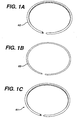
Figure 1 is a side perspective view of a support assembly.Figure 1A is the external portion;Figure 1B is the internal portion; andFigure 1C shows the integrated support assembly; -
Figure 2 is a perspective view of a support assembly locking a graft material in place; -
Figure 3 is a perspective view of a straight portion of a prosthesis; -
Figure 4 is a perspective view of a curved or angular portion of a prosthesis; and -
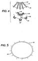
Figure 5 is an alternative embodiment of an inner ring of the invention. - Throughout the figures and the description below, like numerals indicate the same element.
- Each of the components of the system will now be described in more detail. Any references to the Figures will be used to illustrate one or more exemplary embodiments of the invention, without intending to limit the invention thereby.
- A prosthesis of the present invention includes a support assembly covered by or supporting at least one covering material, such as a graft material. The support assembly and cover material define an interior space having an open proximal end and an open distal end. The graft material may comprise a wide variety of materials, may be configured in a wide variety of shapes, and their shapes and uses are well known in the art. Exemplary materials for use with this aspect of the invention are disclosed in
US-4,739,762 (Palmaz) andUS-4,776,337 (Palmaz). - The support assembly comprises a plurality of support structures each having an outer portion and an inner portion, both of which are complementary structures between which a graft material or gasket material may be sandwiched. In the exemplary embodiments shown in
Figures 1-4 ,support structure 61 comprises an outer portion in the form of anouter ring 62 and an inner portion in the form of aninner ring 63. - The outer portion is a
metal ring 62. - The inner portion is a
metal ring 63. - The
outer ring 62 andinner ring 63 are snap-fit to each other. The graft material is sandwiched and anchored between the inner and outer portions. Advantageously, in this embodiment, the graft material is anchored to the support assembly without puncturing the graft material. The flexibility of the inner and outer portions allows the graft material to flex which increases the flexibility of the prosthesis while reducing the potential for kinking. In addition, the flexibility of the inner and outer portions allows the prosthesis to be readily crimped and placed into a delivery system. - One skilled in the art will readily recognize that an inner or outer portion of the support assembly may be configured or adapted to include certain features and/or to perform a certain function(s), and that alternate designs may be used to promote those features or functions. For example, the interior surface of the outer portion and/or the outer surface of the inner portion may include one or more protrusions, e.g., ribs, spikes, nubs, or the like. The preferred alternative structure is shown in Figure 6, in which the
inner ring 63 includes one ormore spikes 64. These protrusions are intended to engage the graft or gasket material so as to anchor the graft material to the ring, either by abutting the graft material, or by passing through the graft material. - In one exemplary embodiment, one or more rings may be radiopaque for increased visibility through the vasculature. In another exemplary embodiment, the proximal and distal rings have greater radial and longitudinal strength than the rings therebetween. This creates a porsthesis having stiff ends for anchoring, but a more flexible body for navigation through the vasculature. The stiffer ends may be accomplished by changing the stiffness of the ring or clip, or by varying the heat treatment of the end rings during manufacture. The rings allow the prosthesis to bend more easily, and generally provide for more flexibility when the prosthesis is being delivered through a tortuous vessel. When a non-compliant graft is attached to a support, the strength of the support assembly scaffolds any graft from folding into the blood flow lumen, while maintaining a tight kink radius.
- Any of the support assembly structures of the present invention may be formed of any material suitable for functioning in vivo as a support for graft material. A support structure of the present invention may be formed of a wide variety of materials, all of which are well known to those skilled in the art. In some exemplary embodiments of the invention, the inner and outer ring may be formed from a metal or metal alloy. In preferred embodiments of the invention, the support structure's may be formed from superelastic Nickel Titanium alloys (Nitinol). Descriptions of medical devices which use such alloys can be found in
US-4,665,906 andEP-A-0928606 . A support structure according to the present invention is preferably laser cut from a piece of superelastic Nickel Titanium alloy, such as nitinol, and thereafter treated so as to exhibit shaped memory properties at body temperature. - The graft material may be variously configured, preferably to achieve predetermined mechanical properties. For example, the graft material may incorporate a single or multiple weaving and/or pleating patterns, or may be pleated or unpleated. For example, the graft may be configured into a plain weave, a satin weave, include continuous longitudinal pleats, interrupted pleats, annular or helical pleats, radially oriented pleats, or combinations thereof. Alternately, the graft material may be knitted or braided. In the exemplary embodiments of the invention in which the graft material is pleated, the pleats may be continuous or discontinuous. Also, the pleats may be oriented longitudinally, circumferentially, or combinations thereof.
- Placing one portion of the support assembly closer together on the graft material forms a curve in the prosthesis. Compare
Figures 3 and4 . As shown, maintaining an equal length of graft material between successive support assemblies forms a straight segment (seeFigure 3 ). Providing a shorter length of graft material in one area of the support assembly as compared to another area allows the prosthesis to bend (seeFigure 4 ). - In order to reduce or eliminate corrosion problems, it is desirable to metallically isolate
support assemblies 61 from other metallic components. Accordingly, as illustrated inFigure 3 ,support structures 61 are spaced from each other.
Claims (8)
- A prosthesis defining a fluid flow path comprising: a cover (60) and a support assembly supporting the cover (60), the support assembly including one or more support structures (61); wherein each support structure includes an outer portion (62) matingly connected to an inner portion (63), said cover (60) being sandwiched between the outer (62) and inner (63) portions, and characterised in that the inner portion is snap fit inside the outer portion, and in that the outer portion (62) comprises a metal ring and the inner portion comprises a metal ring.
- The prosthesis of claim 1 wherein said support assembly and cover (60) define a fluid flow path through the prosthesis.
- The prosthesis of claim 1 wherein the support assembly is formed from at least one metal.
- The prosthesis of claim 3 wherein the support assembly is formed from a nickel titanium alloy.
- The prosthesis of claim 4 wherein the support assembly is formed from nitinol.
- The prosthesis of claim 1 wherein at least one of the support structures (61) is radiopaque.
- The prosthesis of claim 1 wherein the proximal and distal rings have greater radial and longitudinal strength than the rings therebetween.
- The prosthesis of claim 1 wherein providing a shorter length of graft material in one area of the support assembly as compared to another area allows the prostesis to be bent.
Applications Claiming Priority (2)
| Application Number | Priority Date | Filing Date | Title |
|---|---|---|---|
| US10/695,289 US7189255B2 (en) | 2003-10-28 | 2003-10-28 | Prosthesis support ring assembly |
| US695289 | 2003-10-28 |
Publications (3)
| Publication Number | Publication Date |
|---|---|
| EP1527752A2 EP1527752A2 (en) | 2005-05-04 |
| EP1527752A3 EP1527752A3 (en) | 2005-12-21 |
| EP1527752B1 true EP1527752B1 (en) | 2010-06-16 |
Family
ID=34423353
Family Applications (1)
| Application Number | Title | Priority Date | Filing Date |
|---|---|---|---|
| EP04256582A Not-in-force EP1527752B1 (en) | 2003-10-28 | 2004-10-26 | Prosthesis support ring assembly |
Country Status (6)
| Country | Link |
|---|---|
| US (1) | US7189255B2 (en) |
| EP (1) | EP1527752B1 (en) |
| JP (1) | JP4628748B2 (en) |
| AT (1) | ATE471125T1 (en) |
| CA (1) | CA2485784C (en) |
| DE (1) | DE602004027696D1 (en) |
Families Citing this family (11)
| Publication number | Priority date | Publication date | Assignee | Title |
|---|---|---|---|---|
| US20030114918A1 (en) | 2000-04-28 | 2003-06-19 | Garrison Michi E. | Stent graft assembly and method |
| US7497872B2 (en) * | 2004-03-08 | 2009-03-03 | Cook Incorporated | Retainer for a stent-graft |
| US7318835B2 (en) * | 2004-07-20 | 2008-01-15 | Medtronic Vascular, Inc. | Endoluminal prosthesis having expandable graft sections |
| US7323008B2 (en) * | 2004-08-09 | 2008-01-29 | Medtronic Vascular, Inc. | Flexible stent |
| JP2007144065A (en) * | 2005-11-30 | 2007-06-14 | Kitamura Seisakusho:Kk | Graft and apparatus for mounting interior reinforcement |
| US20080065044A1 (en) * | 2006-09-08 | 2008-03-13 | Abbott Cardiovascular Systems Inc. | Bioactive agent-containing implantable rings |
| EP2262443A2 (en) * | 2008-03-10 | 2010-12-22 | NFocus Neuromedical, Inc. | Stents and stent grafts |
| JP2011224123A (en) * | 2010-04-19 | 2011-11-10 | Kanji Inoue | Stent |
| EP3344185A1 (en) * | 2015-08-31 | 2018-07-11 | Sanford Health | Pre-curved stent graft and methods for use |
| US20170281149A1 (en) * | 2016-03-21 | 2017-10-05 | OriGYN Medical Inc. | Self-retaining radial tissue retractor |
| WO2023022978A1 (en) * | 2021-08-16 | 2023-02-23 | Major Medical Devices, Inc. | Stent-graft device with conforming connector and methods of using the same |
Family Cites Families (26)
| Publication number | Priority date | Publication date | Assignee | Title |
|---|---|---|---|---|
| JPS5024649U (en) * | 1973-07-02 | 1975-03-20 | ||
| US4665906A (en) | 1983-10-14 | 1987-05-19 | Raychem Corporation | Medical devices incorporating sim alloy elements |
| US4733665C2 (en) | 1985-11-07 | 2002-01-29 | Expandable Grafts Partnership | Expandable intraluminal graft and method and apparatus for implanting an expandable intraluminal graft |
| CA1322628C (en) * | 1988-10-04 | 1993-10-05 | Richard A. Schatz | Expandable intraluminal graft |
| ES2081490T3 (en) | 1990-08-28 | 1996-03-16 | Meadox Medicals Inc | VASCULAR GRAFT SELF-SUPPORTING FABRIC. |
| JP3168019B2 (en) * | 1990-12-27 | 2001-05-21 | テルモ株式会社 | Artificial blood vessel reinforcement and artificial blood vessel |
| US6039749A (en) | 1994-02-10 | 2000-03-21 | Endovascular Systems, Inc. | Method and apparatus for deploying non-circular stents and graftstent complexes |
| US6124523A (en) * | 1995-03-10 | 2000-09-26 | Impra, Inc. | Encapsulated stent |
| US6264684B1 (en) | 1995-03-10 | 2001-07-24 | Impra, Inc., A Subsidiary Of C.R. Bard, Inc. | Helically supported graft |
| US5667523A (en) * | 1995-04-28 | 1997-09-16 | Impra, Inc. | Dual supported intraluminal graft |
| WO1996036297A1 (en) * | 1995-05-19 | 1996-11-21 | Kanji Inoue | Transplantation instrument, method of bending same and method of transplanting same |
| US6814747B2 (en) | 1995-09-08 | 2004-11-09 | Anthony Walter Anson | Surgical graft/stent system |
| US6254628B1 (en) * | 1996-12-09 | 2001-07-03 | Micro Therapeutics, Inc. | Intracranial stent |
| US5976183A (en) * | 1998-01-05 | 1999-11-02 | Medical Carbon Research Institute, Llc | Sewing ring for heart valve prosthesis |
| US6342067B1 (en) | 1998-01-09 | 2002-01-29 | Nitinol Development Corporation | Intravascular stent having curved bridges for connecting adjacent hoops |
| US6099559A (en) * | 1998-05-28 | 2000-08-08 | Medtronic Ave, Inc. | Endoluminal support assembly with capped ends |
| AU761192B2 (en) * | 1998-06-10 | 2003-05-29 | Converge Medical, Inc. | Sutureless anastomosis systems |
| US6143022A (en) * | 1998-08-24 | 2000-11-07 | Medtronic Ave, Inc. | Stent-graft assembly with dual configuration graft component and method of manufacture |
| US6558414B2 (en) | 1999-02-02 | 2003-05-06 | Impra, Inc. | Partial encapsulation of stents using strips and bands |
| GB2347861B (en) * | 1999-03-13 | 2003-11-26 | Biointeractions Ltd | Biocompatible endoprostheses |
| AU2001240956A1 (en) * | 2000-03-09 | 2001-09-17 | Diseno Y Desarrollo Medico, S.A. De C.V. | Stent with cover connectors |
| US6379382B1 (en) | 2000-03-13 | 2002-04-30 | Jun Yang | Stent having cover with drug delivery capability |
| US6520984B1 (en) | 2000-04-28 | 2003-02-18 | Cardiovasc, Inc. | Stent graft assembly and method |
| US6254632B1 (en) | 2000-09-28 | 2001-07-03 | Advanced Cardiovascular Systems, Inc. | Implantable medical device having protruding surface structures for drug delivery and cover attachment |
| US6911040B2 (en) | 2002-01-24 | 2005-06-28 | Cordis Corporation | Covered segmented stent |
| US7473271B2 (en) * | 2003-04-11 | 2009-01-06 | Boston Scientific Scimed, Inc. | Stent delivery system with securement and deployment accuracy |
-
2003
- 2003-10-28 US US10/695,289 patent/US7189255B2/en active Active
-
2004
- 2004-10-26 AT AT04256582T patent/ATE471125T1/en not_active IP Right Cessation
- 2004-10-26 EP EP04256582A patent/EP1527752B1/en not_active Not-in-force
- 2004-10-26 DE DE602004027696T patent/DE602004027696D1/en active Active
- 2004-10-26 CA CA2485784A patent/CA2485784C/en not_active Expired - Fee Related
- 2004-10-27 JP JP2004312762A patent/JP4628748B2/en not_active Expired - Fee Related
Also Published As
| Publication number | Publication date |
|---|---|
| CA2485784A1 (en) | 2005-04-28 |
| CA2485784C (en) | 2012-09-04 |
| JP2005131401A (en) | 2005-05-26 |
| JP4628748B2 (en) | 2011-02-09 |
| US7189255B2 (en) | 2007-03-13 |
| EP1527752A2 (en) | 2005-05-04 |
| EP1527752A3 (en) | 2005-12-21 |
| ATE471125T1 (en) | 2010-07-15 |
| DE602004027696D1 (en) | 2010-07-29 |
| US20050090892A1 (en) | 2005-04-28 |
Similar Documents
| Publication | Publication Date | Title |
|---|---|---|
| US10028849B2 (en) | Flexible stent graft | |
| EP1455687B1 (en) | Stent graft with improved graft adhesion | |
| EP0686379B2 (en) | Vascular graft | |
| EP0880948B1 (en) | Stent and stent-graft for treating branched vessels | |
| EP0859576B1 (en) | A surgical graft/stent system | |
| US20060224232A1 (en) | Hybrid modular endovascular graft | |
| JP5421320B2 (en) | Flexible stent graft | |
| EP1537836B1 (en) | Prosthesis graft with z or sinusoidal pleating arranged parallel to the longitudinal axis. | |
| US20020082674A1 (en) | Surgical graft/stent system | |
| JP2001506176A (en) | Sandwich stent | |
| JP2013543416A (en) | Stent graft system | |
| EP1527752B1 (en) | Prosthesis support ring assembly | |
| CN110623780A (en) | Sectional type tectorial membrane stent and preparation method thereof | |
| EP1800620B1 (en) | prosthesis comprising a coiled stent | |
| WO2009145913A1 (en) | Kink-resistant stent graft | |
| CN113893062A (en) | Covered stent | |
| EP4144326A1 (en) | Encapsulated devices with separation layers | |
| EP1477134A2 (en) | Stent and stent-graft for treating branched vessels | |
| US20200268533A1 (en) | Hybrid stent designs | |
| CN117122443A (en) | Branched stent graft with support stent |
Legal Events
| Date | Code | Title | Description |
|---|---|---|---|
| PUAI | Public reference made under article 153(3) epc to a published international application that has entered the european phase |
Free format text: ORIGINAL CODE: 0009012 |
|
| AK | Designated contracting states |
Kind code of ref document: A2 Designated state(s): AT BE BG CH CY CZ DE DK EE ES FI FR GB GR HU IE IT LI LU MC NL PL PT RO SE SI SK TR |
|
| AX | Request for extension of the european patent |
Extension state: AL HR LT LV MK |
|
| PUAL | Search report despatched |
Free format text: ORIGINAL CODE: 0009013 |
|
| AK | Designated contracting states |
Kind code of ref document: A3 Designated state(s): AT BE BG CH CY CZ DE DK EE ES FI FR GB GR HU IE IT LI LU MC NL PL PT RO SE SI SK TR |
|
| AX | Request for extension of the european patent |
Extension state: AL HR LT LV MK |
|
| 17P | Request for examination filed |
Effective date: 20060330 |
|
| AKX | Designation fees paid |
Designated state(s): AT BE BG CH CY CZ DE DK EE ES FI FR GB GR HU IE IT LI LU MC NL PL PT RO SE SI SK TR |
|
| 17Q | First examination report despatched |
Effective date: 20090713 |
|
| GRAP | Despatch of communication of intention to grant a patent |
Free format text: ORIGINAL CODE: EPIDOSNIGR1 |
|
| GRAS | Grant fee paid |
Free format text: ORIGINAL CODE: EPIDOSNIGR3 |
|
| GRAA | (expected) grant |
Free format text: ORIGINAL CODE: 0009210 |
|
| AK | Designated contracting states |
Kind code of ref document: B1 Designated state(s): AT BE BG CH CY CZ DE DK EE ES FI FR GB GR HU IE IT LI LU MC NL PL PT RO SE SI SK TR |
|
| REG | Reference to a national code |
Ref country code: CH Ref legal event code: EP |
|
| REG | Reference to a national code |
Ref country code: IE Ref legal event code: FG4D |
|
| REF | Corresponds to: |
Ref document number: 602004027696 Country of ref document: DE Date of ref document: 20100729 Kind code of ref document: P |
|
| REG | Reference to a national code |
Ref country code: NL Ref legal event code: T3 |
|
| PG25 | Lapsed in a contracting state [announced via postgrant information from national office to epo] |
Ref country code: SE Free format text: LAPSE BECAUSE OF FAILURE TO SUBMIT A TRANSLATION OF THE DESCRIPTION OR TO PAY THE FEE WITHIN THE PRESCRIBED TIME-LIMIT Effective date: 20100616 |
|
| PG25 | Lapsed in a contracting state [announced via postgrant information from national office to epo] |
Ref country code: AT Free format text: LAPSE BECAUSE OF FAILURE TO SUBMIT A TRANSLATION OF THE DESCRIPTION OR TO PAY THE FEE WITHIN THE PRESCRIBED TIME-LIMIT Effective date: 20100616 Ref country code: SI Free format text: LAPSE BECAUSE OF FAILURE TO SUBMIT A TRANSLATION OF THE DESCRIPTION OR TO PAY THE FEE WITHIN THE PRESCRIBED TIME-LIMIT Effective date: 20100616 Ref country code: FI Free format text: LAPSE BECAUSE OF FAILURE TO SUBMIT A TRANSLATION OF THE DESCRIPTION OR TO PAY THE FEE WITHIN THE PRESCRIBED TIME-LIMIT Effective date: 20100616 |
|
| PG25 | Lapsed in a contracting state [announced via postgrant information from national office to epo] |
Ref country code: PL Free format text: LAPSE BECAUSE OF FAILURE TO SUBMIT A TRANSLATION OF THE DESCRIPTION OR TO PAY THE FEE WITHIN THE PRESCRIBED TIME-LIMIT Effective date: 20100616 Ref country code: GR Free format text: LAPSE BECAUSE OF FAILURE TO SUBMIT A TRANSLATION OF THE DESCRIPTION OR TO PAY THE FEE WITHIN THE PRESCRIBED TIME-LIMIT Effective date: 20100917 Ref country code: CY Free format text: LAPSE BECAUSE OF FAILURE TO SUBMIT A TRANSLATION OF THE DESCRIPTION OR TO PAY THE FEE WITHIN THE PRESCRIBED TIME-LIMIT Effective date: 20100616 |
|
| PG25 | Lapsed in a contracting state [announced via postgrant information from national office to epo] |
Ref country code: EE Free format text: LAPSE BECAUSE OF FAILURE TO SUBMIT A TRANSLATION OF THE DESCRIPTION OR TO PAY THE FEE WITHIN THE PRESCRIBED TIME-LIMIT Effective date: 20100616 |
|
| PG25 | Lapsed in a contracting state [announced via postgrant information from national office to epo] |
Ref country code: PT Free format text: LAPSE BECAUSE OF FAILURE TO SUBMIT A TRANSLATION OF THE DESCRIPTION OR TO PAY THE FEE WITHIN THE PRESCRIBED TIME-LIMIT Effective date: 20101018 Ref country code: BE Free format text: LAPSE BECAUSE OF FAILURE TO SUBMIT A TRANSLATION OF THE DESCRIPTION OR TO PAY THE FEE WITHIN THE PRESCRIBED TIME-LIMIT Effective date: 20100616 Ref country code: CZ Free format text: LAPSE BECAUSE OF FAILURE TO SUBMIT A TRANSLATION OF THE DESCRIPTION OR TO PAY THE FEE WITHIN THE PRESCRIBED TIME-LIMIT Effective date: 20100616 Ref country code: SK Free format text: LAPSE BECAUSE OF FAILURE TO SUBMIT A TRANSLATION OF THE DESCRIPTION OR TO PAY THE FEE WITHIN THE PRESCRIBED TIME-LIMIT Effective date: 20100616 Ref country code: RO Free format text: LAPSE BECAUSE OF FAILURE TO SUBMIT A TRANSLATION OF THE DESCRIPTION OR TO PAY THE FEE WITHIN THE PRESCRIBED TIME-LIMIT Effective date: 20100616 |
|
| PLBE | No opposition filed within time limit |
Free format text: ORIGINAL CODE: 0009261 |
|
| STAA | Information on the status of an ep patent application or granted ep patent |
Free format text: STATUS: NO OPPOSITION FILED WITHIN TIME LIMIT |
|
| PG25 | Lapsed in a contracting state [announced via postgrant information from national office to epo] |
Ref country code: DK Free format text: LAPSE BECAUSE OF FAILURE TO SUBMIT A TRANSLATION OF THE DESCRIPTION OR TO PAY THE FEE WITHIN THE PRESCRIBED TIME-LIMIT Effective date: 20100616 |
|
| 26N | No opposition filed |
Effective date: 20110317 |
|
| PG25 | Lapsed in a contracting state [announced via postgrant information from national office to epo] |
Ref country code: MC Free format text: LAPSE BECAUSE OF NON-PAYMENT OF DUE FEES Effective date: 20101031 |
|
| REG | Reference to a national code |
Ref country code: CH Ref legal event code: PL |
|
| REG | Reference to a national code |
Ref country code: DE Ref legal event code: R097 Ref document number: 602004027696 Country of ref document: DE Effective date: 20110316 |
|
| PG25 | Lapsed in a contracting state [announced via postgrant information from national office to epo] |
Ref country code: LI Free format text: LAPSE BECAUSE OF NON-PAYMENT OF DUE FEES Effective date: 20101031 Ref country code: CH Free format text: LAPSE BECAUSE OF NON-PAYMENT OF DUE FEES Effective date: 20101031 |
|
| PG25 | Lapsed in a contracting state [announced via postgrant information from national office to epo] |
Ref country code: LU Free format text: LAPSE BECAUSE OF NON-PAYMENT OF DUE FEES Effective date: 20101026 Ref country code: BG Free format text: LAPSE BECAUSE OF FAILURE TO SUBMIT A TRANSLATION OF THE DESCRIPTION OR TO PAY THE FEE WITHIN THE PRESCRIBED TIME-LIMIT Effective date: 20100616 Ref country code: HU Free format text: LAPSE BECAUSE OF FAILURE TO SUBMIT A TRANSLATION OF THE DESCRIPTION OR TO PAY THE FEE WITHIN THE PRESCRIBED TIME-LIMIT Effective date: 20101217 |
|
| PG25 | Lapsed in a contracting state [announced via postgrant information from national office to epo] |
Ref country code: TR Free format text: LAPSE BECAUSE OF FAILURE TO SUBMIT A TRANSLATION OF THE DESCRIPTION OR TO PAY THE FEE WITHIN THE PRESCRIBED TIME-LIMIT Effective date: 20100616 |
|
| PG25 | Lapsed in a contracting state [announced via postgrant information from national office to epo] |
Ref country code: BG Free format text: LAPSE BECAUSE OF FAILURE TO SUBMIT A TRANSLATION OF THE DESCRIPTION OR TO PAY THE FEE WITHIN THE PRESCRIBED TIME-LIMIT Effective date: 20100916 |
|
| PG25 | Lapsed in a contracting state [announced via postgrant information from national office to epo] |
Ref country code: ES Free format text: LAPSE BECAUSE OF FAILURE TO SUBMIT A TRANSLATION OF THE DESCRIPTION OR TO PAY THE FEE WITHIN THE PRESCRIBED TIME-LIMIT Effective date: 20100927 |
|
| PGFP | Annual fee paid to national office [announced via postgrant information from national office to epo] |
Ref country code: FR Payment date: 20141008 Year of fee payment: 11 Ref country code: IE Payment date: 20141009 Year of fee payment: 11 Ref country code: GB Payment date: 20141022 Year of fee payment: 11 Ref country code: DE Payment date: 20141023 Year of fee payment: 11 |
|
| PGFP | Annual fee paid to national office [announced via postgrant information from national office to epo] |
Ref country code: NL Payment date: 20141010 Year of fee payment: 11 |
|
| PGFP | Annual fee paid to national office [announced via postgrant information from national office to epo] |
Ref country code: IT Payment date: 20141013 Year of fee payment: 11 |
|
| REG | Reference to a national code |
Ref country code: DE Ref legal event code: R119 Ref document number: 602004027696 Country of ref document: DE |
|
| GBPC | Gb: european patent ceased through non-payment of renewal fee |
Effective date: 20151026 |
|
| REG | Reference to a national code |
Ref country code: NL Ref legal event code: MM Effective date: 20151101 |
|
| REG | Reference to a national code |
Ref country code: IE Ref legal event code: MM4A |
|
| PG25 | Lapsed in a contracting state [announced via postgrant information from national office to epo] |
Ref country code: IT Free format text: LAPSE BECAUSE OF NON-PAYMENT OF DUE FEES Effective date: 20151026 Ref country code: DE Free format text: LAPSE BECAUSE OF NON-PAYMENT OF DUE FEES Effective date: 20160503 Ref country code: GB Free format text: LAPSE BECAUSE OF NON-PAYMENT OF DUE FEES Effective date: 20151026 |
|
| REG | Reference to a national code |
Ref country code: FR Ref legal event code: ST Effective date: 20160630 |
|
| PG25 | Lapsed in a contracting state [announced via postgrant information from national office to epo] |
Ref country code: FR Free format text: LAPSE BECAUSE OF NON-PAYMENT OF DUE FEES Effective date: 20151102 Ref country code: NL Free format text: LAPSE BECAUSE OF NON-PAYMENT OF DUE FEES Effective date: 20151101 |
|
| PG25 | Lapsed in a contracting state [announced via postgrant information from national office to epo] |
Ref country code: IE Free format text: LAPSE BECAUSE OF NON-PAYMENT OF DUE FEES Effective date: 20151026 |