EP1527977A2 - Electrical steering system for manned or unmanned operation - Google Patents
Electrical steering system for manned or unmanned operation Download PDFInfo
- Publication number
- EP1527977A2 EP1527977A2 EP04105324A EP04105324A EP1527977A2 EP 1527977 A2 EP1527977 A2 EP 1527977A2 EP 04105324 A EP04105324 A EP 04105324A EP 04105324 A EP04105324 A EP 04105324A EP 1527977 A2 EP1527977 A2 EP 1527977A2
- Authority
- EP
- European Patent Office
- Prior art keywords
- steering
- operator
- shaft
- electric motor
- electrical
- Prior art date
- Legal status (The legal status is an assumption and is not a legal conclusion. Google has not performed a legal analysis and makes no representation as to the accuracy of the status listed.)
- Granted
Links
- 238000000034 method Methods 0.000 description 26
- 230000007257 malfunction Effects 0.000 description 3
- 238000010586 diagram Methods 0.000 description 2
- 208000003443 Unconsciousness Diseases 0.000 description 1
- 230000003213 activating effect Effects 0.000 description 1
- 239000000853 adhesive Substances 0.000 description 1
- 230000001070 adhesive effect Effects 0.000 description 1
- 230000003321 amplification Effects 0.000 description 1
- 238000013500 data storage Methods 0.000 description 1
- 238000001514 detection method Methods 0.000 description 1
- 230000007246 mechanism Effects 0.000 description 1
- 238000003199 nucleic acid amplification method Methods 0.000 description 1
Images


Classifications
-
- B—PERFORMING OPERATIONS; TRANSPORTING
- B62—LAND VEHICLES FOR TRAVELLING OTHERWISE THAN ON RAILS
- B62D—MOTOR VEHICLES; TRAILERS
- B62D1/00—Steering controls, i.e. means for initiating a change of direction of the vehicle
- B62D1/24—Steering controls, i.e. means for initiating a change of direction of the vehicle not vehicle-mounted
- B62D1/28—Steering controls, i.e. means for initiating a change of direction of the vehicle not vehicle-mounted non-mechanical, e.g. following a line or other known markers
- B62D1/286—Systems for interrupting non-mechanical steering due to driver intervention
Definitions
- This invention relates to an electrical steering system for manned or unmanned operation of a vehicle.
- Vehicles may be classified as manned, unmanned or dual-operation. Dual-operation refers to vehicles that support both manned and unmanned operation. An unmanned vehicle may not require a steering wheel. In contrast, an operator of a manned vehicle or a dual-operation vehicle typically requires a steering wheel to direct the vehicle in the desired direction. For a dual-operation vehicle, an operator may occupy a vehicle that operates in an automatic pilot or auto-steering mode where the vehicle follows a desired path plan or trajectory. If the vehicle is presented with an obstacle in its path or deviates from the desired path plan or trajectory, the operator may desire to seize control of the steering. Thus, there is a need for detecting the presence of an operator attempting to operate a steering wheel and turning control of the vehicle to the operator.
- a method and system for controlling an electrical steering system supports both manned and unmanned operation of a steering system for a vehicle.
- a steering wheel is coupled to an electric motor shaft for rotation with the steering wheel.
- a torque transducer senses a torque level for an application of rotational force applied to the steering wheel.
- An operator detector detects a presence or absence of an operator based on the sensed torque. The steering system is controlled based on the detected presence or absence of the operator.
- FIG. 1 is a block diagram of an electrical steering system for manned or unmanned operation of a vehicle.
- FIG. 2 is a flow chart of one illustrative example of a method of controlling an electrical steering system for manned and unmanned operation.
- FIG. 3 is a flow chart of another illustrative example of a method of controlling an electrical steering system.
- FIG. 4 illustrates a procedure for controlling the steering of a steering system in greater detail than FIG. 3.
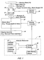
- FIG. 1 illustrates a block diagram of one possible embodiment of an electrical steering system. Other embodiments are possible and may fall within the scope of the claims.
- the electrical steering system comprises a steering wheel 10 that is connected to an upper shaft 12.
- a torque transducer 15 is mounted to or associated with the upper shaft 12.
- the upper shaft 12, the motor shaft 20 or both may include mounting hardware for mounting the torque transducer 15.
- the motor shaft 20 is associated with an electric motor 22.
- a through-shaft electric motor is used as the electric motor 22
- one end of the motor shaft 20 is associated with the transducer 15, whereas the other end of the motor shaft 20 is connected to a steering assembly 28.
- An output of the torque transducer 15 is electrically or electromagnetically coupled to an operator detector 24 that detects the presence or absence of an operator of the steering wheel 10 or the vehicle.
- the operator detector 24 provides a status signal or status data to the steering controller 26 that indicates the presence or absence of the operator.
- the steering controller 26 is electrically or electromagnetically coupled to the electric motor 22.
- Vehicular electronics 30 may be coupled to the steering controller 26.
- the vehicular electronics 30 includes an obstacle detector 32, a location-determining receiver 34, and a path planning module 38 that are coupled to a guidance module 36.
- the location-determining receiver 34 comprises a Global Positioning System (GPS) receiver, a GPS receiver with differential correction, a Loran receiver, a Loran C receiver or another receiver that provides location data on a location or position of a vehicle.
- the path planning module 38 may dynamically provide a path plan or access a path plan that is pre-programmed or stored in data storage of the vehicular electronics 30.
- the path plan specifies the position or location data versus time for the vehicle.
- the path plan may extend from an initial position to a destination position through various intermediate positions.
- the obstacle detector 32 comprises a detector for determining whether an obstacle is present near the path plan or within an obstacle detection zone of a vehicle.
- the obstacle detector 32 may warn the guidance module 36 of the estimated or actual location of an obstacle.
- the guidance module 36 may provide steering instructions to the steering controller 26, propulsion instructions to a propulsion controller, and braking instructions to a braking controller such that the vehicle follows a path plan. Further, the guidance module 36 may depart from the path plan or may momentarily stop to the vehicle to avoid striking an obstacle detected by the obstacle detector 32, to keep a certain minimum clearance from an obstacle or to otherwise take precautionary, evasive or safety measures.
- the steering wheel 10 may be connected to the upper shaft 12 by a spline at the end of the upper shaft 12, a slot in the upper shaft 12 with a key, a clamp around the cylindrical outer surface of the upper shaft 12, a mounting flange or by any other suitable mechanical connection.
- the upper shaft 12 may be supported by radial bearings 14.
- the radial bearings 14 may be mounted in a housing or attached to a unibody structure, a frame or another structural component of a vehicle. As shown in FIG. 1, one end of the upper shaft 12 terminates in a mounting flange 18. Similarly, one end of the motor shaft 20 terminates in a mounting flange 18.
- the torque transducer 15 may be mounted to the mounting flanges 18 by fasteners 16, clamps, adhesive or other means.
- the output of the torque transducer 15 is electrically, electromagnetically or wirelessly coupled to an operator detector 24.
- the motor shaft 20 may be supported by its internal bearings alone or an optional bearing 17 may be added to support the portion of the motor shaft
- the mounting flanges 18 may be replaced by another mounting arrangement for the torque transducer 15.
- other mounting arrangements include clamps or securing mechanisms for securing a transducer to one or more shafts.
- the torque transducer 15 comprises a strain gauge, a piezoelectric sensor or another transducer or device for converting mechanical force into electrical energy.
- the torque transducer 15 may comprise an in-line rotary torque transducer 15 that senses torque within a desired range for a typical human operator.
- the transducer may be capable of sensing torque from two-inch pounds to one-hundred inch pounds or greater.
- the transducer output may represent a sensed torque reading versus time, which is continuously or periodically sent from the transducer 15 to the operator detector 24 for processing.
- the electric motor 22 comprises a through-shaft alternating current (AC) electric motor.
- the electric motor 22 may comprise a high-torque, gearless, brushless, through-shaft AC motor which does not significantly impede manual operation by a user when or if the operator applies rotational energy to the electric motor 22 via the steering wheel and the upper shaft 12.
- Any configuration of an electric motor may be used for the electric motor 22 including direct current motors, alternating current motors, switched reluctance motors, variable speed motors or otherwise provided that the electric motor 22 does not provide significant resistance to turning when not energized or has a clutch for decoupling the motor's rotor from the motor shaft 12 when the electric motor 22 is not energized.
- the electric motor 22 may have a motor shaft that is not a through-shaft.
- a non-through motor shaft is oriented generally parallel to any steering shaft that interconnects the steering wheel 10 to the steering assembly 28 and such that the motor shaft is mechanically coupled (e.g., via a gear, rollers, chain or belt) for rotational movement with the steering shaft.
- the steering assembly 28 may comprise a rack-and-pinion steering system, a mechanical linkage that converts rotation movement of a shaft (e.g., motor shaft 20) to lateral movement or another steering system.
- a shaft e.g., motor shaft 20
- the steering assembly 28 supports an Ackerman steering configuration. In another embodiment, the steering assembly 28 supports four-wheel steering configuration.
- a steering wheel 10 is mechanically coupled to the upper shaft 12 for rotation with the upper shaft 12.
- An electric motor 22 e.g., a through-shaft electric motor
- a steering controller 26 is arranged for controlling the electric motor 22.
- a torque transducer 15 is connected to the upper shaft 12 for sensing a torque placed on the steering wheel 10.
- a steering assembly 28 for directing one or more wheels of the vehicle is mechanically coupled to the electric motor 22.
- An operator detector 24 is electrically or electromagnetically coupled to the torque transducer 15.
- the operator detector 24 detects a presence of the operator by torque meeting or exceeding a threshold minimum torque level.
- the operator detector 24 sends an operator present or operator absent signal to the steering controller 26.
- the steering controller 26 follows a steering command issued by a guidance module 36 when an operator absent status signal is provided to the steering controller 26.
- the steering controller 26 follows, defers to or does not interfere with a steering commend issued by a human operator via the steering wheel 10 when an operator present signal is provided to the steering controller 26.
- the steering controller 26 may assist the operator by providing power-assisted steering or power steering when the operator is present to amplify a steering operator's physical input to the steering wheel 10.
- the steering controller 26 may not send any steering commands to the electric motor 22 other than to de-energize or shut-down the electric motor 22 or to decouple the electric motor 22 from the mechanical connection between the steering wheel 10 and the steering assembly 28.
- the steering controller 26 has a first mode in which the human operator turns a shaft of the electric motor 22 by application of force to the steering wheel 10 and a second mode in which the steering controller 26 turns the shaft by the application of electrical energy to the electric motor 22, consistent with steering commands from a guidance module 36.
- a failure mode may represent a failure, malfunction or performance problem associated with at least one of the following: electric motor 22, the operator detector 24, the steering controller 26, and the torque transducer 15.
- the failure mode supports immediate and reliable operation in the first mode or manual turning of the steering wheel 10 by the user that results in turning of the steerable wheels of the vehicle.
- the steering controller 26 switches from the first mode to the second mode if the operator detector 24 does not provide an operator present signal within a predefined time interval.
- FIG. 2 is a flow chart on a method for controlling an electrical steering system for manned or unmanned operation. The method of FIG. 2 begins in step S100.
- a steering wheel 10 is mechanically coupled to an electric motor shaft for rotation with an the steering wheel 10.
- the steering wheel 10 is mechanically coupled to the electric motor 22 via an upper shaft 12 attached to the steering wheel 10.
- a torque transducer 15 senses a torque level of any rotational force applied to the steering wheel 10.
- the torque transducer 15 may comprise an in-line torque transducer 15 or another transducer associated with the motor shaft 20.
- an operator detector 24 detects a presence or absence of an operator based on the sensed torque. For instance, an operator detector 24 may detect a presence of the operator by a torque meeting or exceeding a threshold minimum torque level. The operator detector 24 may send an operator present status signal or an operator absent status signal to the steering controller 26, depending upon the sensed torque level(s) or a statistical interpretation thereof.
- a steering controller 26 controls the steering based on the detected presence or absence of the operator.
- the steering controller 26 may follow a steering command issued by a guidance module 36 when an operator absent signal is outputted.
- the steering controller 26 may follow a steering command issued by a human operator via the steering wheel 10 when an operator present signal is outputted.
- the steering controller 26 may be configured, but need not be configured, to provide power assist to the operator during operator control of the steering.
- FIG. 3 shows another flow chart of a method for controlling an electric steering system.
- the method of FIG. 3 is similar to the method of FIG. 2, except the method of step S200, step S202, and step S204 collectively replace step S104 of FIG. 2.
- step S206 of FIG. 3 replaces step S106 of FIG. 2.
- an operator detector 24 or data processor determines whether or not the sensed torque (e.g., torque levels versus time stamps) of step S102 meets or exceeds a threshold minimum torque value.
- the threshold minimum torque value may be selected by any of the following methods, among others: empirical tests, technical tests, operator surveys, product focus groups or a user profile. With respect to selection of a threshold minimum torque based on a user profile, the threshold minimum torque may be less for a female operator than for a male operator. Similarly, the threshold minimum torque may be less for a lower weight person than for a higher weight person.
- piezoelectric sensors are built into the driver's seat and the user profile or threshold minimum torque value is selected based on the operator's weight.
- step S202 If the sensed torque level meets or exceeds a threshold minimum torque level, the method continues in step S202. However, if the sensed torque level does not meet or exceed a threshold minimum torque level, the method continues in step S204.
- an operator detector 24 sends a present status signal indicating the operator is present.
- the operator detector 24 sends the present status signal to the steering controller 26.
- step S204 the operator detector 24 sends an operator absent signal indicating an operator is absent, unconscious, sleeping, fatigued, ill, injured or incapacitated. For instance, the operator detector 24 sends the absent status signal to the steering controller 26.
- step S206 the steering controller 26 controls the steering based on the sent status signal.
- the sent status signal means the present status signal or the absent status signal.
- the controller 26 controls the steering system differently if the absent status signal is received versus the present status signal.
- FIG. 4 illustrates step S206 in greater detail than FIG. 3 does.
- the procedure of FIG. 4 begins in step S300.
- step S300 the steering controller 26 determines whether the operator absent status signal has been received. If the operator absent status signal has been received, the method continues with step S302. However, if the operator status signal as not been received, the method continues with step S304.
- step S302 the steering controller 26 steers in a second mode in which the electric motor 22 turns the motor shaft 20 by application of electrical energy to the electric motor 22 in response to the guidance module 36 or the vehicular electronics 30.
- the motor shaft 20 turns the steerable wheels via the steering assembly 28 to direct the vehicle.
- step S304 the steering controller 26 determines whether the operator present status signal has been received. If the operator present status signal has been received, the method continues with step S308. However, if the operator status signal has not been received, then the method may continue in accordance with one of two alternative techniques. Under a first technique, indicated by dashed lines, the method continues with step S306. Under a second technique, indicated by dotted lines, the method continues with step S302 and the method directs the steering controller 26 to steer in the second mode.
- step S308 the steering controller 26 steers in first mode in which a human operator turns a shaft of the electric motor 22 by application of force to the steering wheel 10.
- the user manually operates the steering wheel 10 which is ultimately coupled to the steering assembly 28 via the electric motor 22 (e.g., an electric motor having a through-shaft).
- the steering assembly 28 turns the steerable wheels via the steering assembly 28 to direct the vehicle in accordance with operator input at the steering wheel 10.
- the steering controller 26 may not, but need not, provide user-assistance or amplification of manual user input to the steering wheel 10 by activating the electric motor 22 during the first mode to assist manual user input.
- Step S306 may follow multiple steps in FIG. 4, including step S302, step S304 or step S308.
- the electrical steering system waits for a timer to expire.
- the timer may be set to any suitable interval and may range from milliseconds to minutes, depending upon the algorithm chosen to steer the vehicle.
- the interval may provide some delay or hysteresis such that the steering system does not oscillate from a first mode to a second mode because the operator is on a straight road or has not applied any force to the steering wheel 10 for a brief instant.
- the steering controller 26 may switch to the second mode to maintain control of the vehicle if an operator is present, but does not apply sufficiently frequent input to maintain the steering system in the first mode.
- the method may return to step S102.
- step S306 allows for changes in the operating mode during operation of the vehicle from one time interval to the next time interval.
- the steering controller 26 switches from the first mode to the second mode during or after the subsequent interval.
- the operator may have fallen asleep during the subsequent interval or may have become incapacitated during the subsequent interval. The shorter the interval, the greater the chance that a crash or accident is avoided from a sleeping, fatigued, dozing, inattentive or incapacitated operator.
- a failure, malfunction or performance problem of at least one of the electric motor 22, the operator detector 24, the steering controller 26, and the torque transducer 15 may result in switching from the second mode to the first mode during the current interval immediately after discovery of the failure, malfunction or performance problem.
- the first mode an operator can maintain control or seize control of the vehicle if the vehicle stops steering on its own and such a failure is apparent from operation of the vehicle, diagnostic gauges, warning instrumentation or the like.
Abstract
Description
- This invention relates to an electrical steering system for manned or unmanned operation of a vehicle.
- Vehicles may be classified as manned, unmanned or dual-operation. Dual-operation refers to vehicles that support both manned and unmanned operation. An unmanned vehicle may not require a steering wheel. In contrast, an operator of a manned vehicle or a dual-operation vehicle typically requires a steering wheel to direct the vehicle in the desired direction. For a dual-operation vehicle, an operator may occupy a vehicle that operates in an automatic pilot or auto-steering mode where the vehicle follows a desired path plan or trajectory. If the vehicle is presented with an obstacle in its path or deviates from the desired path plan or trajectory, the operator may desire to seize control of the steering. Thus, there is a need for detecting the presence of an operator attempting to operate a steering wheel and turning control of the vehicle to the operator.
- A method and system for controlling an electrical steering system supports both manned and unmanned operation of a steering system for a vehicle. A steering wheel is coupled to an electric motor shaft for rotation with the steering wheel. A torque transducer senses a torque level for an application of rotational force applied to the steering wheel. An operator detector detects a presence or absence of an operator based on the sensed torque. The steering system is controlled based on the detected presence or absence of the operator.
- FIG. 1 is a block diagram of an electrical steering system for manned or unmanned operation of a vehicle.
- FIG. 2 is a flow chart of one illustrative example of a method of controlling an electrical steering system for manned and unmanned operation.
- FIG. 3 is a flow chart of another illustrative example of a method of controlling an electrical steering system.
- FIG. 4 illustrates a procedure for controlling the steering of a steering system in greater detail than FIG. 3.
- FIG. 1. illustrates a block diagram of one possible embodiment of an electrical steering system. Other embodiments are possible and may fall within the scope of the claims. The electrical steering system comprises a
steering wheel 10 that is connected to an upper shaft 12. Atorque transducer 15 is mounted to or associated with the upper shaft 12. The upper shaft 12, themotor shaft 20 or both may include mounting hardware for mounting thetorque transducer 15. Themotor shaft 20 is associated with anelectric motor 22. For the illustrative configuration of FIG. 1 where a through-shaft electric motor is used as theelectric motor 22, one end of themotor shaft 20 is associated with thetransducer 15, whereas the other end of themotor shaft 20 is connected to asteering assembly 28. An output of thetorque transducer 15 is electrically or electromagnetically coupled to anoperator detector 24 that detects the presence or absence of an operator of thesteering wheel 10 or the vehicle. Theoperator detector 24 provides a status signal or status data to thesteering controller 26 that indicates the presence or absence of the operator. Thesteering controller 26 is electrically or electromagnetically coupled to theelectric motor 22.Vehicular electronics 30 may be coupled to thesteering controller 26. - The
vehicular electronics 30 includes anobstacle detector 32, a location-determiningreceiver 34, and apath planning module 38 that are coupled to aguidance module 36. The location-determiningreceiver 34 comprises a Global Positioning System (GPS) receiver, a GPS receiver with differential correction, a Loran receiver, a Loran C receiver or another receiver that provides location data on a location or position of a vehicle. Thepath planning module 38 may dynamically provide a path plan or access a path plan that is pre-programmed or stored in data storage of thevehicular electronics 30. The path plan specifies the position or location data versus time for the vehicle. The path plan may extend from an initial position to a destination position through various intermediate positions. Theobstacle detector 32 comprises a detector for determining whether an obstacle is present near the path plan or within an obstacle detection zone of a vehicle. Theobstacle detector 32 may warn theguidance module 36 of the estimated or actual location of an obstacle. Theguidance module 36 may provide steering instructions to thesteering controller 26, propulsion instructions to a propulsion controller, and braking instructions to a braking controller such that the vehicle follows a path plan. Further, theguidance module 36 may depart from the path plan or may momentarily stop to the vehicle to avoid striking an obstacle detected by theobstacle detector 32, to keep a certain minimum clearance from an obstacle or to otherwise take precautionary, evasive or safety measures. - The
steering wheel 10 may be connected to the upper shaft 12 by a spline at the end of the upper shaft 12, a slot in the upper shaft 12 with a key, a clamp around the cylindrical outer surface of the upper shaft 12, a mounting flange or by any other suitable mechanical connection. The upper shaft 12 may be supported byradial bearings 14. Theradial bearings 14 may be mounted in a housing or attached to a unibody structure, a frame or another structural component of a vehicle. As shown in FIG. 1, one end of the upper shaft 12 terminates in amounting flange 18. Similarly, one end of themotor shaft 20 terminates in amounting flange 18. Thetorque transducer 15 may be mounted to themounting flanges 18 byfasteners 16, clamps, adhesive or other means. The output of thetorque transducer 15 is electrically, electromagnetically or wirelessly coupled to anoperator detector 24. Themotor shaft 20 may be supported by its internal bearings alone or an optional bearing 17 may be added to support the portion of themotor shaft 20 near thetorque transducer 15. - In an alternate embodiment, the
mounting flanges 18 may be replaced by another mounting arrangement for thetorque transducer 15. For instance, other mounting arrangements include clamps or securing mechanisms for securing a transducer to one or more shafts. - In general, the
torque transducer 15 comprises a strain gauge, a piezoelectric sensor or another transducer or device for converting mechanical force into electrical energy. In one configuration, thetorque transducer 15 may comprise an in-linerotary torque transducer 15 that senses torque within a desired range for a typical human operator. For example, the transducer may be capable of sensing torque from two-inch pounds to one-hundred inch pounds or greater. The transducer output may represent a sensed torque reading versus time, which is continuously or periodically sent from thetransducer 15 to theoperator detector 24 for processing. - In one embodiment, the
electric motor 22 comprises a through-shaft alternating current (AC) electric motor. For example, theelectric motor 22 may comprise a high-torque, gearless, brushless, through-shaft AC motor which does not significantly impede manual operation by a user when or if the operator applies rotational energy to theelectric motor 22 via the steering wheel and the upper shaft 12. Any configuration of an electric motor may be used for theelectric motor 22 including direct current motors, alternating current motors, switched reluctance motors, variable speed motors or otherwise provided that theelectric motor 22 does not provide significant resistance to turning when not energized or has a clutch for decoupling the motor's rotor from the motor shaft 12 when theelectric motor 22 is not energized. Although anelectric motor 22 having a through-shaft is shown in FIG. 1 for illustrative purposes, theelectric motor 22 may have a motor shaft that is not a through-shaft. Such a non-through motor shaft is oriented generally parallel to any steering shaft that interconnects thesteering wheel 10 to thesteering assembly 28 and such that the motor shaft is mechanically coupled (e.g., via a gear, rollers, chain or belt) for rotational movement with the steering shaft. - The
steering assembly 28 may comprise a rack-and-pinion steering system, a mechanical linkage that converts rotation movement of a shaft (e.g., motor shaft 20) to lateral movement or another steering system. In one embodiment, thesteering assembly 28 supports an Ackerman steering configuration. In another embodiment, thesteering assembly 28 supports four-wheel steering configuration. - A
steering wheel 10 is mechanically coupled to the upper shaft 12 for rotation with the upper shaft 12. An electric motor 22 (e.g., a through-shaft electric motor) is capable of receiving a rotational input from the upper shaft 12. A steeringcontroller 26 is arranged for controlling theelectric motor 22. Atorque transducer 15 is connected to the upper shaft 12 for sensing a torque placed on thesteering wheel 10. A steeringassembly 28 for directing one or more wheels of the vehicle is mechanically coupled to theelectric motor 22. - An
operator detector 24 is electrically or electromagnetically coupled to thetorque transducer 15. Theoperator detector 24 detects a presence of the operator by torque meeting or exceeding a threshold minimum torque level. Theoperator detector 24 sends an operator present or operator absent signal to thesteering controller 26. - The steering
controller 26 follows a steering command issued by aguidance module 36 when an operator absent status signal is provided to thesteering controller 26. The steeringcontroller 26 follows, defers to or does not interfere with a steering commend issued by a human operator via thesteering wheel 10 when an operator present signal is provided to thesteering controller 26. The steeringcontroller 26 may assist the operator by providing power-assisted steering or power steering when the operator is present to amplify a steering operator's physical input to thesteering wheel 10. Alternatively, the steeringcontroller 26 may not send any steering commands to theelectric motor 22 other than to de-energize or shut-down theelectric motor 22 or to decouple theelectric motor 22 from the mechanical connection between thesteering wheel 10 and thesteering assembly 28. - The steering
controller 26 has a first mode in which the human operator turns a shaft of theelectric motor 22 by application of force to thesteering wheel 10 and a second mode in which thesteering controller 26 turns the shaft by the application of electrical energy to theelectric motor 22, consistent with steering commands from aguidance module 36. A failure mode may represent a failure, malfunction or performance problem associated with at least one of the following:electric motor 22, theoperator detector 24, the steeringcontroller 26, and thetorque transducer 15. The failure mode supports immediate and reliable operation in the first mode or manual turning of thesteering wheel 10 by the user that results in turning of the steerable wheels of the vehicle. In one configuration, to maintain reliable steering control of the vehicle, the steeringcontroller 26 switches from the first mode to the second mode if theoperator detector 24 does not provide an operator present signal within a predefined time interval. - FIG. 2 is a flow chart on a method for controlling an electrical steering system for manned or unmanned operation. The method of FIG. 2 begins in step S100.
- In step S100, a
steering wheel 10 is mechanically coupled to an electric motor shaft for rotation with an thesteering wheel 10. For example, thesteering wheel 10 is mechanically coupled to theelectric motor 22 via an upper shaft 12 attached to thesteering wheel 10. - In step S102, a
torque transducer 15 senses a torque level of any rotational force applied to thesteering wheel 10. Thetorque transducer 15 may comprise an in-line torque transducer 15 or another transducer associated with themotor shaft 20. - In step S104, an
operator detector 24 detects a presence or absence of an operator based on the sensed torque. For instance, anoperator detector 24 may detect a presence of the operator by a torque meeting or exceeding a threshold minimum torque level. Theoperator detector 24 may send an operator present status signal or an operator absent status signal to thesteering controller 26, depending upon the sensed torque level(s) or a statistical interpretation thereof. - In step S106, a
steering controller 26 controls the steering based on the detected presence or absence of the operator. The steeringcontroller 26 may follow a steering command issued by aguidance module 36 when an operator absent signal is outputted. The steeringcontroller 26 may follow a steering command issued by a human operator via thesteering wheel 10 when an operator present signal is outputted. However, the steeringcontroller 26 may be configured, but need not be configured, to provide power assist to the operator during operator control of the steering. - FIG. 3 shows another flow chart of a method for controlling an electric steering system. The method of FIG. 3 is similar to the method of FIG. 2, except the method of step S200, step S202, and step S204 collectively replace step S104 of FIG. 2. In addition, step S206 of FIG. 3 replaces step S106 of FIG. 2.
- In step S200, an
operator detector 24 or data processor determines whether or not the sensed torque (e.g., torque levels versus time stamps) of step S102 meets or exceeds a threshold minimum torque value. The threshold minimum torque value may be selected by any of the following methods, among others: empirical tests, technical tests, operator surveys, product focus groups or a user profile. With respect to selection of a threshold minimum torque based on a user profile, the threshold minimum torque may be less for a female operator than for a male operator. Similarly, the threshold minimum torque may be less for a lower weight person than for a higher weight person. In one embodiment, piezoelectric sensors are built into the driver's seat and the user profile or threshold minimum torque value is selected based on the operator's weight. - If the sensed torque level meets or exceeds a threshold minimum torque level, the method continues in step S202. However, if the sensed torque level does not meet or exceed a threshold minimum torque level, the method continues in step S204.
- In step S202, an
operator detector 24 sends a present status signal indicating the operator is present. For example, theoperator detector 24 sends the present status signal to thesteering controller 26. - In step S204, the
operator detector 24 sends an operator absent signal indicating an operator is absent, unconscious, sleeping, fatigued, ill, injured or incapacitated. For instance, theoperator detector 24 sends the absent status signal to thesteering controller 26. - After step S202 or step S204, the method continues in step S206. In step S206, the steering
controller 26 controls the steering based on the sent status signal. The sent status signal means the present status signal or the absent status signal. Thecontroller 26 controls the steering system differently if the absent status signal is received versus the present status signal. - FIG. 4 illustrates step S206 in greater detail than FIG. 3 does. The procedure of FIG. 4 begins in step S300.
- In step S300, the steering
controller 26 determines whether the operator absent status signal has been received. If the operator absent status signal has been received, the method continues with step S302. However, if the operator status signal as not been received, the method continues with step S304. - In step S302, the steering
controller 26 steers in a second mode in which theelectric motor 22 turns themotor shaft 20 by application of electrical energy to theelectric motor 22 in response to theguidance module 36 or thevehicular electronics 30. In turn, themotor shaft 20 turns the steerable wheels via thesteering assembly 28 to direct the vehicle. - In step S304, the steering
controller 26 determines whether the operator present status signal has been received. If the operator present status signal has been received, the method continues with step S308. However, if the operator status signal has not been received, then the method may continue in accordance with one of two alternative techniques. Under a first technique, indicated by dashed lines, the method continues with step S306. Under a second technique, indicated by dotted lines, the method continues with step S302 and the method directs thesteering controller 26 to steer in the second mode. - In step S308, the steering
controller 26 steers in first mode in which a human operator turns a shaft of theelectric motor 22 by application of force to thesteering wheel 10. Here, the user manually operates thesteering wheel 10 which is ultimately coupled to thesteering assembly 28 via the electric motor 22 (e.g., an electric motor having a through-shaft). The steeringassembly 28 turns the steerable wheels via thesteering assembly 28 to direct the vehicle in accordance with operator input at thesteering wheel 10. The steeringcontroller 26 may not, but need not, provide user-assistance or amplification of manual user input to thesteering wheel 10 by activating theelectric motor 22 during the first mode to assist manual user input. - Step S306 may follow multiple steps in FIG. 4, including step S302, step S304 or step S308. In step S306, the electrical steering system waits for a timer to expire. The timer may be set to any suitable interval and may range from milliseconds to minutes, depending upon the algorithm chosen to steer the vehicle. In one embodiment, the interval may provide some delay or hysteresis such that the steering system does not oscillate from a first mode to a second mode because the operator is on a straight road or has not applied any force to the
steering wheel 10 for a brief instant. In another embodiment, the steeringcontroller 26 may switch to the second mode to maintain control of the vehicle if an operator is present, but does not apply sufficiently frequent input to maintain the steering system in the first mode. After step S306, the method may return to step S102. - The loop from step S306 to step S102 allows for changes in the operating mode during operation of the vehicle from one time interval to the next time interval. In one example, where the steering is in the first mode during the previous interval, if the
operator detector 24 does not provide an operator present signal within a subsequent time interval of the timer, the steeringcontroller 26 switches from the first mode to the second mode during or after the subsequent interval. Here, the operator may have fallen asleep during the subsequent interval or may have become incapacitated during the subsequent interval. The shorter the interval, the greater the chance that a crash or accident is avoided from a sleeping, fatigued, dozing, inattentive or incapacitated operator. In another example, where steering is in a second mode during a previous interval or in a current interval, a failure, malfunction or performance problem of at least one of theelectric motor 22, theoperator detector 24, the steeringcontroller 26, and thetorque transducer 15 may result in switching from the second mode to the first mode during the current interval immediately after discovery of the failure, malfunction or performance problem. In the first mode, an operator can maintain control or seize control of the vehicle if the vehicle stops steering on its own and such a failure is apparent from operation of the vehicle, diagnostic gauges, warning instrumentation or the like.
Claims (11)
- An electrical steering system comprising:a shaft (12);a steering wheel (10) coupled to the shaft (12) for rotation with the shaft (12);an electric motor (22) capable of receiving a rotational input from the shaft (12);a torque transducer (15) connected to the shaft (12) for sensing a torque placed on the steering wheel (10);a steering assembly (28) coupled to at least one of the electric motor (22) and the shaft (12);an operator detector (24) electrically or electromagnetically coupled to the torque transducer (15); anda steering controller (26) for controlling the electric motor (22).
- The electrical steering system according to claim 1 wherein the electric motor (22) has through-shaft and wherein one end of the motor shaft is connected to the shaft (12) and another end is connected to the steering assembly (28).
- The electrical steering system according to claim 1 wherein the torque transducer (15) comprises at least one of the following: a strain gauge and a piezo-electric sensor.
- The electrical steering system according to claim 1 wherein the operator detector (24) detects a presence of the operator by torque meeting or exceeding a threshold minimum torque level.
- The electrical steering system according to claim 1 wherein the operator detector (24) sends an operator present or operator absent signal to the steering controller (26).
- The electrical steering system according to claim 1 wherein the steering controller (26) follows a steering command issued by a guidance module (36) when an
- The electrical steering system according to claim 1 wherein the steering controller (26) follows a steering command issued by a human operator via the steering wheel (10) when an operator present signal is provided to the steering controller (26).
- The electrical steering system according to claim 1 wherein the steering control has a first mode in which a human operator turns a shaft (20) of the electric motor (22) by application of force to the steering wheel (10) and a second mode in which the steering controller turns the shaft by the application of electrical energy to the electric motor (22).
- The electrical steering system according to claim 8 wherein a failure mode of at least one of the electric motor (22), the operator detector (24), the steering controller (26), and the torque transducer (15) allows operation in the first mode.
- The electrical steering system according to claim 8 wherein the steering controller (26) switches from the first mode to the second mode if the operator detector (24) does not provide an operator present signal within a predefined time interval.
- The electrical steering system according to claim 8 wherein the electric motor (22) provides power assistance to the operator's manual turning of the shaft (12) in the first mode.
Applications Claiming Priority (2)
| Application Number | Priority Date | Filing Date | Title |
|---|---|---|---|
| US697345 | 2000-10-27 | ||
| US10/697,345 US6988583B2 (en) | 2003-10-30 | 2003-10-30 | Electrical steering system for manned or unmanned operation |
Publications (3)
| Publication Number | Publication Date |
|---|---|
| EP1527977A2 true EP1527977A2 (en) | 2005-05-04 |
| EP1527977A3 EP1527977A3 (en) | 2006-08-23 |
| EP1527977B1 EP1527977B1 (en) | 2008-04-16 |
Family
ID=34423392
Family Applications (1)
| Application Number | Title | Priority Date | Filing Date |
|---|---|---|---|
| EP04105324A Active EP1527977B1 (en) | 2003-10-30 | 2004-10-27 | Electrical steering system for manned or unmanned operation |
Country Status (3)
| Country | Link |
|---|---|
| US (3) | US6988583B2 (en) |
| EP (1) | EP1527977B1 (en) |
| DE (1) | DE602004013104T2 (en) |
Cited By (3)
| Publication number | Priority date | Publication date | Assignee | Title |
|---|---|---|---|---|
| WO2009032030A1 (en) * | 2007-09-06 | 2009-03-12 | Tsd Integrated Controls, Llc | Method and apparatus for vehicle auto-guidance |
| CN110126911A (en) * | 2019-04-02 | 2019-08-16 | 上海衡鲁汽车科技有限公司 | A kind of unmanned redundancy transfer meeting ASIL_D standard and its control method |
| CN110654457A (en) * | 2018-06-29 | 2020-01-07 | 比亚迪股份有限公司 | Vehicle and steering control system, method and device of vehicle |
Families Citing this family (28)
| Publication number | Priority date | Publication date | Assignee | Title |
|---|---|---|---|---|
| US9043016B2 (en) | 2005-10-21 | 2015-05-26 | Deere & Company | Versatile robotic control module |
| AU2011213807B2 (en) * | 2005-10-21 | 2014-05-22 | Deere & Company | Systems and methods for switching between autonomous and manual operation of a vehicle |
| US8983680B2 (en) * | 2006-08-24 | 2015-03-17 | Kairos Autonmi, Inc. | Unmanned vehicle retrofitting system |
| EP2080685B1 (en) * | 2008-01-16 | 2011-04-27 | Ford Global Technologies, LLC | Rotational torque sensing by means of integrated strain gauge |
| US8100220B2 (en) * | 2008-03-28 | 2012-01-24 | Rexius Forest By-Products, Inc. | Vehicle having auxiliary steering system |
| US8237389B2 (en) * | 2008-11-12 | 2012-08-07 | Irobot Corporation | Multi mode safety control module |
| US9164508B1 (en) | 2009-04-16 | 2015-10-20 | Kairos Autonomi | Unmanned vehicle retrofitting system |
| WO2010139013A1 (en) | 2009-06-02 | 2010-12-09 | Topcon Precision Agriculture Pty Ltd | Vehicle guidance system |
| US8544964B2 (en) | 2010-06-29 | 2013-10-01 | Deere & Company | Brake control system for dual mode vehicle |
| US8793036B2 (en) * | 2010-09-22 | 2014-07-29 | The Boeing Company | Trackless transit system with adaptive vehicles |
| KR20130064540A (en) * | 2011-12-08 | 2013-06-18 | 현대자동차주식회사 | System and method for controlling electric power steering apparatus of vehicle |
| CN102941876B (en) * | 2012-11-23 | 2015-11-04 | 南京理工大学 | Automatic driving vehicle steering swivel system and control method thereof |
| US9844880B1 (en) | 2014-08-07 | 2017-12-19 | Kairos Autonomi, Inc. | Unmanned vehicle retrofitting applique assembly |
| CN104199432A (en) * | 2014-09-24 | 2014-12-10 | 奇瑞汽车股份有限公司 | Longitudinal intelligence control system for unmanned automobile |
| DE102014224082A1 (en) * | 2014-11-26 | 2016-06-02 | Robert Bosch Gmbh | A method of operating a vehicle and operating a manufacturing system |
| DE102015201032B4 (en) * | 2015-01-22 | 2018-12-20 | Volkswagen Aktiengesellschaft | Steering system for automated driving of a motor vehicle |
| US10077056B1 (en) | 2015-04-24 | 2018-09-18 | State Farm Mutual Automobile Insurance Company | Managing self-driving behavior of autonomous or semi-autonomous vehicle based upon actual driving behavior of driver |
| US10832331B1 (en) * | 2016-07-11 | 2020-11-10 | State Farm Mutual Automobile Insurance Company | Systems and methods for allocating fault to autonomous vehicles |
| JP6460065B2 (en) * | 2016-08-25 | 2019-01-30 | トヨタ自動車株式会社 | Control device for hybrid vehicle |
| JP6528743B2 (en) * | 2016-08-26 | 2019-06-12 | トヨタ自動車株式会社 | Vehicle control device |
| US10515390B2 (en) | 2016-11-21 | 2019-12-24 | Nio Usa, Inc. | Method and system for data optimization |
| US10471829B2 (en) | 2017-01-16 | 2019-11-12 | Nio Usa, Inc. | Self-destruct zone and autonomous vehicle navigation |
| US10837790B2 (en) | 2017-08-01 | 2020-11-17 | Nio Usa, Inc. | Productive and accident-free driving modes for a vehicle |
| US10635109B2 (en) | 2017-10-17 | 2020-04-28 | Nio Usa, Inc. | Vehicle path-planner monitor and controller |
| US10606274B2 (en) | 2017-10-30 | 2020-03-31 | Nio Usa, Inc. | Visual place recognition based self-localization for autonomous vehicles |
| US10935978B2 (en) | 2017-10-30 | 2021-03-02 | Nio Usa, Inc. | Vehicle self-localization using particle filters and visual odometry |
| JP2019034736A (en) * | 2018-11-26 | 2019-03-07 | トヨタ自動車株式会社 | Hybrid-vehicular control apparatus |
| CN111196310B (en) * | 2020-01-21 | 2022-06-07 | 南京艾格慧元农业科技有限公司 | Self-induction type reversing device and method for agricultural machinery electrically-driven steering wheel |
Citations (6)
| Publication number | Priority date | Publication date | Assignee | Title |
|---|---|---|---|---|
| EP0125918A2 (en) * | 1983-05-17 | 1984-11-21 | John Wiles | Power operated or power assisted vehicle steering system |
| US6178365B1 (en) * | 1997-09-13 | 2001-01-23 | Honda Giken Kogyo Kabushiki Kaisha | Steering control system for vehicle |
| EP1106473A1 (en) * | 1999-12-10 | 2001-06-13 | Renault V.I. | Method and device for steering command of a vehicle, especially an utility vehicle |
| US6408236B2 (en) * | 2000-06-27 | 2002-06-18 | Mitsubishi Denki Kabushiki Kaisha | Automotive vehicle steering control device |
| EP1275573A2 (en) * | 2001-07-13 | 2003-01-15 | Nissan Motor Company, Limited | Lane-keep control system for vehicle |
| EP1350707A2 (en) * | 2002-04-03 | 2003-10-08 | Robert Bosch Gmbh | Lateral guiding assistance device for vehicles |
Family Cites Families (25)
| Publication number | Priority date | Publication date | Assignee | Title |
|---|---|---|---|---|
| US2340849A (en) * | 1941-10-22 | 1944-02-08 | Frank W Wildeboor | Lawn mower |
| US3217479A (en) * | 1963-04-29 | 1965-11-16 | Scott & Sons Co O M | Combined height adjustment for reel mower |
| US4335569A (en) * | 1980-10-22 | 1982-06-22 | The Toro Company | Reel to bedknife adjustment system |
| US4479346A (en) * | 1981-03-31 | 1984-10-30 | Noel Chandler | Automatic electrical bed knife adjuster |
| US4606178A (en) * | 1984-12-24 | 1986-08-19 | Textron Inc. | Lawnmower reel-to-bedknife adjustment system |
| US4663924A (en) * | 1985-09-27 | 1987-05-12 | Textron Inc. | Apparatus and method for establishing reel-to-bedknife clearance |
| GB9318639D0 (en) * | 1993-09-08 | 1993-10-27 | Adwest Eng Ltd | Electrically powered steering mechanism |
| JP3523698B2 (en) * | 1994-12-21 | 2004-04-26 | 光洋精工株式会社 | Electric power steering device and preventive safety device |
| US5600942A (en) * | 1995-03-31 | 1997-02-11 | New Holland North America, Inc. | Adaptive thresholding for metal detection |
| US5709281A (en) * | 1995-09-14 | 1998-01-20 | Trw Inc. | Method and apparatus for adjusting steering feel |
| JP3668340B2 (en) * | 1996-09-05 | 2005-07-06 | 本田技研工業株式会社 | Vehicle steering device |
| GB9716658D0 (en) * | 1997-08-07 | 1997-10-15 | Lucas Ind Plc | Improvements relating to motors |
| DE19743961A1 (en) * | 1997-10-04 | 1999-04-15 | Mercedes Benz Lenkungen Gmbh | Power steering system for vehicle |
| US6269308B1 (en) * | 1998-08-20 | 2001-07-31 | Honda Giken Kogyo Kabushiki Kaisha | Safety running system for vehicle |
| JP3525872B2 (en) * | 2000-08-01 | 2004-05-10 | トヨタ自動車株式会社 | Automatic steering device for vehicles |
| JP3498910B2 (en) * | 2000-09-05 | 2004-02-23 | 日産自動車株式会社 | Lane tracking controller |
| JP3823018B2 (en) * | 2000-09-08 | 2006-09-20 | 株式会社ジェイテクト | Electric power steering device |
| DE10262194B4 (en) * | 2001-05-18 | 2014-01-23 | Denso Corporation | TORQUE SENSOR AND ELECTRIC POWER STEERING SYSTEM WITH TORQUE SENSOR |
| US6907333B2 (en) * | 2001-09-10 | 2005-06-14 | Toyota Jidosha Kabushiki Kaisha | Steering device |
| US6788930B2 (en) * | 2001-10-02 | 2004-09-07 | Qualcomm Incorporated | Method and system for depleting backlog in a communication system |
| JP4075622B2 (en) | 2002-03-11 | 2008-04-16 | 株式会社デンソー | Control system for electric power steering device |
| JP4043276B2 (en) * | 2002-04-24 | 2008-02-06 | 株式会社日立製作所 | Radar equipment |
| US7121073B2 (en) * | 2003-04-30 | 2006-10-17 | Deere & Company | Cutting reel adjusting system |
| US7114318B2 (en) * | 2003-04-30 | 2006-10-03 | Deere & Company | Height-of-cut adjustment system for reel mower |
| US7231757B2 (en) * | 2003-04-30 | 2007-06-19 | Deere & Company | Method and apparatus for setting and maintaining reel-to-bedknife clearance |
-
2003
- 2003-10-30 US US10/697,345 patent/US6988583B2/en not_active Expired - Lifetime
-
2004
- 2004-10-27 DE DE602004013104T patent/DE602004013104T2/en active Active
- 2004-10-27 EP EP04105324A patent/EP1527977B1/en active Active
-
2005
- 2005-05-11 US US11/126,480 patent/US7073623B2/en active Active
-
2008
- 2008-04-14 US US12/102,264 patent/US20080196377A1/en not_active Abandoned
Patent Citations (6)
| Publication number | Priority date | Publication date | Assignee | Title |
|---|---|---|---|---|
| EP0125918A2 (en) * | 1983-05-17 | 1984-11-21 | John Wiles | Power operated or power assisted vehicle steering system |
| US6178365B1 (en) * | 1997-09-13 | 2001-01-23 | Honda Giken Kogyo Kabushiki Kaisha | Steering control system for vehicle |
| EP1106473A1 (en) * | 1999-12-10 | 2001-06-13 | Renault V.I. | Method and device for steering command of a vehicle, especially an utility vehicle |
| US6408236B2 (en) * | 2000-06-27 | 2002-06-18 | Mitsubishi Denki Kabushiki Kaisha | Automotive vehicle steering control device |
| EP1275573A2 (en) * | 2001-07-13 | 2003-01-15 | Nissan Motor Company, Limited | Lane-keep control system for vehicle |
| EP1350707A2 (en) * | 2002-04-03 | 2003-10-08 | Robert Bosch Gmbh | Lateral guiding assistance device for vehicles |
Cited By (5)
| Publication number | Priority date | Publication date | Assignee | Title |
|---|---|---|---|---|
| WO2009032030A1 (en) * | 2007-09-06 | 2009-03-12 | Tsd Integrated Controls, Llc | Method and apparatus for vehicle auto-guidance |
| US9051006B2 (en) | 2007-09-06 | 2015-06-09 | Tsd Integrated Controls, Llc | Method and apparatus for vehicle auto-guidance |
| CN110654457A (en) * | 2018-06-29 | 2020-01-07 | 比亚迪股份有限公司 | Vehicle and steering control system, method and device of vehicle |
| CN110126911A (en) * | 2019-04-02 | 2019-08-16 | 上海衡鲁汽车科技有限公司 | A kind of unmanned redundancy transfer meeting ASIL_D standard and its control method |
| CN110126911B (en) * | 2019-04-02 | 2023-12-08 | 上海衡鲁汽车科技有限公司 | Unmanned redundant steering device meeting ASIL_D standard and control method thereof |
Also Published As
| Publication number | Publication date |
|---|---|
| US20050092542A1 (en) | 2005-05-05 |
| US20080196377A1 (en) | 2008-08-21 |
| EP1527977B1 (en) | 2008-04-16 |
| US6988583B2 (en) | 2006-01-24 |
| EP1527977A3 (en) | 2006-08-23 |
| US7073623B2 (en) | 2006-07-11 |
| DE602004013104T2 (en) | 2009-05-20 |
| DE602004013104D1 (en) | 2008-05-29 |
| US20050247513A1 (en) | 2005-11-10 |
Similar Documents
| Publication | Publication Date | Title |
|---|---|---|
| US7073623B2 (en) | Electrical steering system for manned or unmanned operation | |
| CN108163042B (en) | Vehicle steering system with user experience based automatic to manual driving transition system and method | |
| US6097286A (en) | Steer by wire system with feedback | |
| US6782968B2 (en) | Automatic steering apparatus for vehicle and control method of same | |
| US8874301B1 (en) | Autonomous vehicle with driver presence and physiological monitoring | |
| JP3493568B2 (en) | Car steering system | |
| EP1602552B1 (en) | Driving support system and method | |
| US5101922A (en) | Rear wheel steering system with fail-safe system | |
| US6250421B1 (en) | Power-assisted steering system and method with compensation of pull induced by tire pressure loss | |
| JP2575522Y2 (en) | Power steering device | |
| KR101976866B1 (en) | Motor driven power steering apparatus having steering wheel vibration function for warning driver | |
| US20050283291A1 (en) | Failsafe steering device for steer-by-wire system | |
| JP4007200B2 (en) | Electric power steering device | |
| JP2007039017A (en) | Vehicle operation assisting device | |
| JP3578488B2 (en) | Automatic steering device | |
| US11447179B2 (en) | Method for determining the rack-and-pinion position in a steering system having an electric servomotor | |
| US8838339B2 (en) | Method for determining a torque on a steering train | |
| JPH10217988A (en) | Steering controller | |
| JPH0321331Y2 (en) | ||
| JP3577190B2 (en) | Steering control device | |
| JPH0952578A (en) | Power steering device | |
| US8005593B2 (en) | Method for determining a torque on a steering train of a vehicle with dynamic drive system | |
| JPH0622151U (en) | Power steering system | |
| JPH0713653U (en) | Electric rear wheel steering system | |
| JPH10310075A (en) | Steering device for vehicle |
Legal Events
| Date | Code | Title | Description |
|---|---|---|---|
| PUAI | Public reference made under article 153(3) epc to a published international application that has entered the european phase |
Free format text: ORIGINAL CODE: 0009012 |
|
| AK | Designated contracting states |
Kind code of ref document: A2 Designated state(s): AT BE BG CH CY CZ DE DK EE ES FI FR GB GR HU IE IT LI LU MC NL PL PT RO SE SI SK TR |
|
| AX | Request for extension of the european patent |
Extension state: AL HR LT LV MK |
|
| PUAL | Search report despatched |
Free format text: ORIGINAL CODE: 0009013 |
|
| AK | Designated contracting states |
Kind code of ref document: A3 Designated state(s): AT BE BG CH CY CZ DE DK EE ES FI FR GB GR HU IE IT LI LU MC NL PL PT RO SE SI SK TR |
|
| AX | Request for extension of the european patent |
Extension state: AL HR LT LV MK |
|
| 17P | Request for examination filed |
Effective date: 20070223 |
|
| AKX | Designation fees paid |
Designated state(s): DE FR GB |
|
| 17Q | First examination report despatched |
Effective date: 20070416 |
|
| GRAP | Despatch of communication of intention to grant a patent |
Free format text: ORIGINAL CODE: EPIDOSNIGR1 |
|
| GRAS | Grant fee paid |
Free format text: ORIGINAL CODE: EPIDOSNIGR3 |
|
| GRAA | (expected) grant |
Free format text: ORIGINAL CODE: 0009210 |
|
| AK | Designated contracting states |
Kind code of ref document: B1 Designated state(s): DE FR GB |
|
| REF | Corresponds to: |
Ref document number: 602004013104 Country of ref document: DE Date of ref document: 20080529 Kind code of ref document: P |
|
| ET | Fr: translation filed | ||
| PLBE | No opposition filed within time limit |
Free format text: ORIGINAL CODE: 0009261 |
|
| STAA | Information on the status of an ep patent application or granted ep patent |
Free format text: STATUS: NO OPPOSITION FILED WITHIN TIME LIMIT |
|
| 26N | No opposition filed |
Effective date: 20090119 |
|
| REG | Reference to a national code |
Ref country code: FR Ref legal event code: PLFP Year of fee payment: 12 |
|
| REG | Reference to a national code |
Ref country code: FR Ref legal event code: PLFP Year of fee payment: 13 |
|
| REG | Reference to a national code |
Ref country code: FR Ref legal event code: PLFP Year of fee payment: 14 |
|
| REG | Reference to a national code |
Ref country code: FR Ref legal event code: PLFP Year of fee payment: 15 |
|
| PGFP | Annual fee paid to national office [announced via postgrant information from national office to epo] |
Ref country code: GB Payment date: 20211027 Year of fee payment: 18 |
|
| PGFP | Annual fee paid to national office [announced via postgrant information from national office to epo] |
Ref country code: FR Payment date: 20211025 Year of fee payment: 18 |
|
| GBPC | Gb: european patent ceased through non-payment of renewal fee |
Effective date: 20221027 |
|
| PG25 | Lapsed in a contracting state [announced via postgrant information from national office to epo] |
Ref country code: FR Free format text: LAPSE BECAUSE OF NON-PAYMENT OF DUE FEES Effective date: 20221031 |
|
| PG25 | Lapsed in a contracting state [announced via postgrant information from national office to epo] |
Ref country code: GB Free format text: LAPSE BECAUSE OF NON-PAYMENT OF DUE FEES Effective date: 20221027 |
|
| PGFP | Annual fee paid to national office [announced via postgrant information from national office to epo] |
Ref country code: DE Payment date: 20231031 Year of fee payment: 20 |