EP1532762B1 - Coded mimo systems with selective channel inversion applied per eigenmode - Google Patents
Coded mimo systems with selective channel inversion applied per eigenmode Download PDFInfo
- Publication number
- EP1532762B1 EP1532762B1 EP03791732A EP03791732A EP1532762B1 EP 1532762 B1 EP1532762 B1 EP 1532762B1 EP 03791732 A EP03791732 A EP 03791732A EP 03791732 A EP03791732 A EP 03791732A EP 1532762 B1 EP1532762 B1 EP 1532762B1
- Authority
- EP
- European Patent Office
- Prior art keywords
- group
- transmission channels
- transmission
- channel
- transmit power
- Prior art date
- Legal status (The legal status is an assumption and is not a legal conclusion. Google has not performed a legal analysis and makes no representation as to the accuracy of the status listed.)
- Expired - Fee Related
Links
Images

Classifications
-
- H—ELECTRICITY
- H04—ELECTRIC COMMUNICATION TECHNIQUE
- H04W—WIRELESS COMMUNICATION NETWORKS
- H04W52/00—Power management, e.g. TPC [Transmission Power Control], power saving or power classes
- H04W52/04—TPC
- H04W52/30—TPC using constraints in the total amount of available transmission power
- H04W52/34—TPC management, i.e. sharing limited amount of power among users or channels or data types, e.g. cell loading
- H04W52/346—TPC management, i.e. sharing limited amount of power among users or channels or data types, e.g. cell loading distributing total power among users or channels
-
- H—ELECTRICITY
- H04—ELECTRIC COMMUNICATION TECHNIQUE
- H04B—TRANSMISSION
- H04B7/00—Radio transmission systems, i.e. using radiation field
- H04B7/005—Control of transmission; Equalising
-
- H—ELECTRICITY
- H04—ELECTRIC COMMUNICATION TECHNIQUE
- H04B—TRANSMISSION
- H04B7/00—Radio transmission systems, i.e. using radiation field
- H04B7/02—Diversity systems; Multi-antenna system, i.e. transmission or reception using multiple antennas
- H04B7/04—Diversity systems; Multi-antenna system, i.e. transmission or reception using multiple antennas using two or more spaced independent antennas
- H04B7/0413—MIMO systems
-
- H—ELECTRICITY
- H04—ELECTRIC COMMUNICATION TECHNIQUE
- H04L—TRANSMISSION OF DIGITAL INFORMATION, e.g. TELEGRAPHIC COMMUNICATION
- H04L1/00—Arrangements for detecting or preventing errors in the information received
- H04L1/0001—Systems modifying transmission characteristics according to link quality, e.g. power backoff
- H04L1/0002—Systems modifying transmission characteristics according to link quality, e.g. power backoff by adapting the transmission rate
- H04L1/0003—Systems modifying transmission characteristics according to link quality, e.g. power backoff by adapting the transmission rate by switching between different modulation schemes
-
- H—ELECTRICITY
- H04—ELECTRIC COMMUNICATION TECHNIQUE
- H04L—TRANSMISSION OF DIGITAL INFORMATION, e.g. TELEGRAPHIC COMMUNICATION
- H04L1/00—Arrangements for detecting or preventing errors in the information received
- H04L1/0001—Systems modifying transmission characteristics according to link quality, e.g. power backoff
- H04L1/0009—Systems modifying transmission characteristics according to link quality, e.g. power backoff by adapting the channel coding
-
- H—ELECTRICITY
- H04—ELECTRIC COMMUNICATION TECHNIQUE
- H04L—TRANSMISSION OF DIGITAL INFORMATION, e.g. TELEGRAPHIC COMMUNICATION
- H04L1/00—Arrangements for detecting or preventing errors in the information received
- H04L1/004—Arrangements for detecting or preventing errors in the information received by using forward error control
- H04L1/0041—Arrangements at the transmitter end
-
- H—ELECTRICITY
- H04—ELECTRIC COMMUNICATION TECHNIQUE
- H04L—TRANSMISSION OF DIGITAL INFORMATION, e.g. TELEGRAPHIC COMMUNICATION
- H04L1/00—Arrangements for detecting or preventing errors in the information received
- H04L1/004—Arrangements for detecting or preventing errors in the information received by using forward error control
- H04L1/0056—Systems characterized by the type of code used
- H04L1/0067—Rate matching
- H04L1/0068—Rate matching by puncturing
-
- H—ELECTRICITY
- H04—ELECTRIC COMMUNICATION TECHNIQUE
- H04L—TRANSMISSION OF DIGITAL INFORMATION, e.g. TELEGRAPHIC COMMUNICATION
- H04L1/00—Arrangements for detecting or preventing errors in the information received
- H04L1/004—Arrangements for detecting or preventing errors in the information received by using forward error control
- H04L1/0056—Systems characterized by the type of code used
- H04L1/0071—Use of interleaving
-
- H—ELECTRICITY
- H04—ELECTRIC COMMUNICATION TECHNIQUE
- H04L—TRANSMISSION OF DIGITAL INFORMATION, e.g. TELEGRAPHIC COMMUNICATION
- H04L1/00—Arrangements for detecting or preventing errors in the information received
- H04L1/02—Arrangements for detecting or preventing errors in the information received by diversity reception
- H04L1/06—Arrangements for detecting or preventing errors in the information received by diversity reception using space diversity
-
- H—ELECTRICITY
- H04—ELECTRIC COMMUNICATION TECHNIQUE
- H04B—TRANSMISSION
- H04B7/00—Radio transmission systems, i.e. using radiation field
- H04B7/02—Diversity systems; Multi-antenna system, i.e. transmission or reception using multiple antennas
- H04B7/04—Diversity systems; Multi-antenna system, i.e. transmission or reception using multiple antennas using two or more spaced independent antennas
- H04B7/0413—MIMO systems
- H04B7/0426—Power distribution
- H04B7/0434—Power distribution using multiple eigenmodes
- H04B7/0439—Power distribution using multiple eigenmodes utilizing channel inversion
-
- H—ELECTRICITY
- H04—ELECTRIC COMMUNICATION TECHNIQUE
- H04W—WIRELESS COMMUNICATION NETWORKS
- H04W52/00—Power management, e.g. TPC [Transmission Power Control], power saving or power classes
- H04W52/04—TPC
- H04W52/38—TPC being performed in particular situations
- H04W52/42—TPC being performed in particular situations in systems with time, space, frequency or polarisation diversity
Definitions
- the present invention relates generally to data communication, and more specifically to techniques for performing selective channel inversion per eigenmode for MIMO systems.
- a multiple-input multiple-output (MIMO) communication system employs multiple ( N T ) transmit antennas and multiple ( N R ) receive antennas for data transmission.
- a MIMO channel formed by the N T transmit and N R receive antennas may be decomposed into N S independent channels, with N S ⁇ min ⁇ N T , N R ⁇ .
- Each of the N s independent channels is also referred to as a spatial subchannel or eigenmode of the MIMO channel.
- Such a system is, for example, described in EP 1 117 197 A2.
- the spatial subchannels of a wideband MIMO system may encounter different channel conditions due to various factors such as fading and multipath.
- Each spatial subchannel may thus experience frequency selective fading, which is characterized by different channel gains at different frequencies of the overall system bandwidth. Assuming no power control, this then results in different signal-to-noise-and-interference ratios (SNRs) at different frequencies of each spatial subchannel, which would then be able to support different data rates for a particular level of performance (e.g., 1% packet error rate).
- SNRs signal-to-noise-and-interference ratios
- orthogonal frequency division multiplexing may be used to effectively partition the overall system bandwidth into a number of (N F ) subbands, which are also referred to as frequency bins or subchannels.
- N F frequency bins or subchannels.
- each subband is associated with a respective subcarrier upon which data may be modulated.
- each subband of each spatial subchannel may be-viewed as an independent transmission channel.
- a key challenge in a coded communication system is the selection of the appropriate data rates and coding and modulation schemes to use for a data transmission based on the channel conditions.
- a major goal for the system is to maximize spectral efficiency while reducing complexity for both the transmitter and receiver.
- One straightforward technique for selecting data rates and coding and modulation schemes is to "bit load" each transmission channel in the system according to its transmission capability.
- this technique has several major drawbacks.
- First, coding and modulating individually for each transmission channel can significantly increase the complexity of the processing at both the transmitter and receiver.
- Second, coding individually for each transmission channel may greatly increase coding and decoding delay.
- the available transmission channels are arranged into a number of groups, where each group may include all transmission channels (or frequency bins) for an eigenmode of a MIMO channel.
- the total transmit power is allocated to the groups using a particular power allocation scheme (e.g., uniform power allocation, water-filling, and so on).
- Selective channel inversion is then performed independently for each group selected for use for data transmission (i.e., with non-zero allocated transmit power).
- one or more transmission channels in the group is selected for use, and a scaling factor is determined for each selected channel such that all selected channels for the group are inverted and achieve similar received signal quality (e.g., received SNR).
- the invention further provides methods, program codes, digital signal processors, transmitter units, receiver units, and other apparatuses and elements that implement various aspects, embodiments, and features of the invention, as described in further detail below.
- FIG. 1 graphically illustrates eigenvalue decomposition for a MIMO-OFDM system
- FIG. 2 shows plots of the average spectral efficiency achieved by three transmission schemes for an example 4 ⁇ 4 MIMO system
- FIG. 3 is a block diagram of an access point and a user terminal in the MIMO-OFDM system
- FIG. 4 is a block diagram of a transmitter unit in the access point.
- FIG. 5 is a flow diagram for processing data using selective channel inversion per eigenmode.
- a MIMO communication system such as a multiple-antenna wireless communication system
- the data streams transmitted from the N T transmit antennas interfere with each other at the receiver.
- One technique for combating this interference is to "diagonalize" the MIMO channel to obtain a number of independent channels.
- the channel response can be represented by a constant complex value for the entire system bandwidth, and the elements of the channel response matrix H are scalars.
- the techniques described herein may be extended for frequency selective channels.
- the eigenvalue decomposition may also be performed using singular value decomposition (SVD), which is known in the art.
- SVD singular value decomposition
- the diagonal matrix D contains non-negative real values along the diagonal and zeros elsewhere. These diagonal entries are referred to as the eigenvalues of the matrix R and are indicative of the power gains for the independent channels of the MIMO channel.
- the number of independent channels for a MIMO system with N T transmit and N R receive antennas is the number of non-zero eigenvalues of R , N s ⁇ min ⁇ N T , N R ⁇ .
- the MIMO channel may be diagonalized by pre-multiplying (or "preconditioning") a "data" vector s with the unitary matrix E to obtain the transmitted vector x .
- preconditioning a "data" vector s with the unitary matrix E to obtain the transmitted vector x .
- the received vector y may be pre-multiplied (or "conditioned") with E H H H to obtain an estimate of the data vector s .
- the preconditioning at the transmitter and the conditioning at the receiver result in the data vector s being transformed by an effective channel response represented by the matrix D , as well as a scaling of the noise elements.
- D is a diagonal matrix
- N S non-interfering, parallel channels there are effectively N S non-interfering, parallel channels.
- Each of these channels has a power gain equal to the square of the corresponding eigenvalue, ⁇ i 2 , and a noise power equal to ⁇ 2 ⁇ i for i ⁇ ⁇ 1, ..., N s ⁇ , yielding a signal-to-noise ratio of ⁇ i / ⁇ 2 .
- the power gain of each of these channels is equal to the eigenvalue, ⁇ i , for i ⁇ ⁇ 1,..., N s ⁇ .
- Parallel channel i is often referred to as eigenmode i or mode i .
- the diagonalization of the MIMO channel as shown in equations (3) and (4) can be achieved if the transmitter is provided with the channel response matrix H or equivalent information.
- the eigenvalue decomposition described above may also be performed for a wideband, frequency-selective channel.
- the wideband channel is divided into N F flat-fading, orthogonal frequency bins or subbands.
- the eigenvalue decomposition may then be performed independently for the channel response matrix H (k) for each frequency bin, k, to determine the N S spatial subchannels or eigenmodes for that frequency bin.
- Each spatial subchannel of each frequency bin is also referred to as a "transmission" channel.
- performing eigenmode decomposition for each of the N F frequency bins results in N S spatial subchannels or eigenmodes for each frequency bin, or a total of N S N F transmission channels.
- the eigenvalues may be provided in two forms - a "sorted" form and a "random-order" form.
- the N S eigenvalues for each frequency bin are sorted in decreasing order so that ⁇ 1 ( k ) ⁇ ⁇ 2 ( k ) ⁇ ... ⁇ ⁇ N S ( k ) ⁇ , where ⁇ 1 ( k ) is the largest eigenvalue for frequency bin k and ⁇ N S (k) is the smallest eigenvalue for frequency bin k .
- the ordering of the eigenvalues may be random and further independent of frequency. The particular form selected for use, sorted or random-ordered, influences the selection of the eigenmodes for use for data transmission and the coding and modulation scheme to be used for each selected eigenmode, as described below.
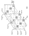
- FIG. 1 graphically illustrates the eigenvalue decomposition for the MIMO-OFDM system.
- Axis 112 may thus be viewed as representing the spatial dimension.
- the set of elements ⁇ i ( k ) ⁇ for each eigenmode is shown by the shaded boxes along a dashed line 114. Each shaded box in FIG. 1 represents a transmission channel. For each eigenmode that experiences frequency selective fading, the elements ⁇ i ( k ) ⁇ for that eigenmode may be different for different values of k .
- eigenmode 1 (which is also referred to as the principal eigenmode) would include the largest eigenvalue, ⁇ 1 ( k ), in each matrix, and eigenmode N S would include the smallest eigenvalue, ⁇ N S (k), in each matrix.
- the eigenvalue decomposition for each frequency bin in the MIMO-OFDM system results in a total of N S N F eigenvalues for the N S N F transmission channels over the entire bandwidth.
- Each transmission channel may achieve a different SNR and may be associated with different transmission capability.
- Various power allocation schemes (or transmission schemes) may be used to distribute the total transmit power to these transmission channels to achieve high overall spectral efficiency, which is given in units of bit/second per Hertz (bps/Hz). Some of these schemes are described in further detail below.
- the "water-filling" or “water-pouring” scheme may be used to optimally distribute the total transmit power across the transmission channels such that the overall spectral efficiency is maximized, under the constraint that the total transmit power at the transmitter is limited to P total .
- the water-filling scheme distributes power over the N S N F transmission channels such that the channels with increasingly higher SNRs receive increasingly greater fractions of the total transmit power.
- the transmit power allocated to a given transmission channel is determined by that channel's SNR, which may be given as ⁇ i ( k )/ ⁇ 2 , where ⁇ i ( k ) is the i -th eigenvalue in the k -th frequency bin.
- the procedure for performing water-filling is known in the art and not described herein.
- the total range of received SNRs expected to be observed may be partitioned into a number of sub-ranges. Each subrange may then be associated with a particular coding and modulation scheme chosen to yield the highest spectral efficiency for a given bit error rate (BER), frame error rate (FER), or packet error rate (PER).
- BER bit error rate
- FER frame error rate
- PER packet error rate
- the water-filling power allocation may result in a different received SNR for each of the N S N F transmission channels. This would then result in the use of many different coding/modulation schemes for the transmission channels.
- the coding/modulation per transmission channel increases the overall spectral efficiency at the expense of greater complexity for both the transmitter and receiver.
- the "SCI-for-all-channels" scheme performs selective channel inversion (SCI) on all transmission channels such that those selected for use achieve approximately equal received SNRs at the receiver. This would then allow a common coding and modulation scheme to be used for all selected transmission channels. This scheme greatly reduces complexity for both the transmitter and receiver in comparison to the water-filling scheme.
- the equalization of the received SNRs may be achieved by first selecting all or only a subset of the N S N F available transmission channels for use for data transmission. The channel selection may result in the elimination of poor channels with low SNRs. The total transmit power P total is then distributed across the selected transmission channels in such a way that the received SNR is approximately equal for all selected transmission channels.
- the total transmit power P total may be allocated such that approximately equal signal power is received for all these channels.
- the normalization factor, ⁇ ensures approximately equal received signal power for all transmission channels, which is given as ⁇ P total .
- the total transmit power is thus effectively distributed (unevenly) across all available transmission channels based on their channel power gains, which is given by the eigenvalues ⁇ i ( k ).
- transmission channels whose received powers are at or above a particular threshold ⁇ relative to the total received power are selected for use for data transmission. Transmission channels whose received powers fall below this threshold are discarded and not used.
- the transmit power to be allocated to the channel is determined as described above, such that all selected transmission channels are received at approximately equal power levels.
- the threshold ⁇ may be selected to maximize spectral efficiency or based on some other criterion.
- the threshold ⁇ may be derived as described below (in Section 3.2).
- a transmission channel is selected for use if its eigenvalue (or channel power gain) is greater than or equal to a power threshold (i.e., ⁇ i ( k ) ⁇ ⁇ P avg ). Since the normalization factor ⁇ is computed based only on the selected transmission channels, the total transmit power P total is distributed to the selected transmission channels based on their channel gains such that all selected transmission channels have approximately equal received power, which may be expressed as ⁇ P total .
- the equalization of the received SNRs for all selected transmission channels can thus be achieved by non-uniform distribution of the total transmit power across these channels.
- the approximately equal received SNRs would then allow the use of a single data rate and a common coding/modulation scheme for all selected transmission channels, which would greatly reduce complexity.
- the "SCI-per-eigenmode" scheme performs selective channel inversion independently for each eigenmode to provide improved performance.
- the N S N F transmission channels are arranged into N S groups such that each group includes all N F frequency bins for a given eigenmode (i.e., group i includes the spatial subchannels for all N F frequency bins for eigenmode i ) . There is thus one group for each eigenmode.
- the SCI-per-eigenmode scheme includes two steps. In the first step, the total transmit power P total is distributed to the N S groups based on a particular group power allocation scheme. In the second step, selective channel inversion is performed independently for each group to distribute that group's allocated transmit power to the N F frequency bins in the group. Each of these steps is described in further detail below.
- the total transmit power P total may be distributed to the N S groups in various manners, some of which are described below.
- the total transmit power P total is distributed uniformly across all N S groups such that they are all allocated equal power.
- the total transmit power P total is distributed to the N s groups based on water-filling across all available transmission channels.
- the total transmit power, P total is first distributed to all N S N F transmission channels using water-filling, as described above.
- the transmit power allocated to each group can then be determined by summing over the transmit powers allocated to the N F transmission channels in that group.
- the total transmit power P total is distributed to the N S groups based on water-filling across all groups using their average channel SNRs.
- Water-filling is then performed to distribute the total transmit power P total across the N S groups based on their average channel SNRs.
- the transmit power allocated to each of the N s groups is denoted as P G (i) , for i ⁇ ⁇ 1,..., N s ⁇ .
- the total transmit power P total is distributed to the N S groups based on water-filling across all groups using the received SNRs of the transmission channels after channel inversion.
- the received SNR, ⁇ i ( k ) , for each frequency bin is next determined based on the initial power allocation P ⁇ i ( k ), as shown in equation (8).
- the total transmit power P total is then distributed to the N S groups using water-filling based on their average received SNRs, ⁇ avg ( i ) for i ⁇ ⁇ 1,..., N s ⁇ .
- the results of the water-filling power allocation are revised (i.e., final) transmit power allocations P G ( i ) , for i ⁇ ⁇ 1, ..., N s ⁇ , for the N s groups.
- Selective channel inversion is again performed independently for each group to distribute the group's allocated transmit power P G ( i ) to the frequency bins in the group. Each frequency bin would then be allocated transmit power P i ( k ) by the second selective channel inversion.
- the second selective channel inversion need not be performed for a given group if (1) the revised transmit power allocated to the group by the water-filling is greater than the initial uniform power allocation (i.e., P G (i) > P ⁇ G ( i )) and (2) all frequency bins in the group were selected for use in the initial selective channel inversion.
- Equation (19) may be used because (1) all frequency bins in the group have already been selected for use and no additional frequency bin can be selected even though the revised power allocation P G ( i ) for the group is higher than the initial power allocation P ⁇ G (i), and (2) the initial selective channel inversion already determines the proper distribution of power to the frequency bins in the group to achieve approximately equal received SNRs for these channels. In all other cases, the selective channel inversion is performed again for each group to determine the transmit power allocations, P i ( k ) for k ⁇ ⁇ 1,..., N F ⁇ , for the frequency bins in the group.
- selective channel inversion is performed independently for each of the N S groups and on the N F frequency bins within each group.
- the selective channel inversion for each group may be performed as follows.
- the summation of the inverse channel power gains in equation (22) takes into account the channel power gains over all selected frequency bins of group i.
- the threshold ⁇ i to select frequency bins for use in each group may be set based on various criteria, e.g., to optimize spectral efficiency.
- the threshold ⁇ i is set based on the channel power gains (or eigenvalues) and the spectral efficiencies of the selected frequency bins based on uniform transmit power allocation across the frequency bins in each group, as described below.
- the spectral efficiency for the ⁇ best frequency bins is computed, where "best" refers to the frequency bins with the highest power gains, G i ( ⁇ ).
- ⁇ is a scale factor used to account for inefficiencies in the coding and modulation scheme selected for use.
- the spectral efficiency C i ( ⁇ ) is computed for each value of ⁇ , where ⁇ ⁇ ⁇ 1, ..., N F ⁇ , and stored in an array. After all N F values of C i ( ⁇ ) have been computed for the N F possible combinations of selected frequency bins, the array of spectral efficiencies is traversed and the largest value of C i ( ⁇ ) is determined. The value of ⁇ , ⁇ max , corresponding to the largest C i ( ⁇ ) is then the number of frequency bins that results in the maximum spectral efficiency for the channel conditions being evaluated and using uniform transmit power allocation.
- the spectral efficiency increases as more frequency bins are selected for use until the optimal point is reached, after which the spectral efficiency decreases because more of the group's transmit power is allocated to poorer frequency bins.
- the spectral efficiency C i ( ⁇ ) for each new value of ⁇ may be compared against the spectral efficiency C i ( ⁇ -1) for the previous value of ⁇ . The computation may then be terminated if the optimal spectral efficiency is reached, which is indicated by C i ( ⁇ ) ⁇ C i ( ⁇ -1).
- the threshold ⁇ i may also be set based on some other criterion or some other power allocation scheme (instead of uniform allocation).
- Performing selective channel inversion independently for each group results in a set of transmit power allocations, P i (k) for k ⁇ ⁇ 1, ..., N F ⁇ , for the N F frequency bins in each group.
- the selective channel inversion may result in less than N F frequency bins being selected for use for any given group.
- the power allocations for the selected frequency bins are such that these bins achieve approximately equal received SNRs. This then allows a single data rate and a common coding/modulation scheme to be used for all selected frequency bins in each group.
- the eigenvalues ⁇ i ( k ), for i ⁇ ⁇ 1, ..., N s ⁇ , for each diagonal matrix D (k) are sorted such that the diagonal elements with smaller indices are generally larger.
- Eigenmode 1 would then be associated with the largest eigenvalue in each of the N F diagonal matrices
- eigenmode 2 would be associated with the second largest eigenvalue, and so on.
- the eigenmodes with lower indices are not likely to have too many bad frequency bins (if any) and excessive transmit power is not used for bad bins.
- the number of eigenmodes selected for use may be reduced at low SNRs.
- the sorted form thus has the advantage that at low SNRs, the coding and modulation are further simplified through the reduction in the number of eigenmodes selected for use.
- the eigenvalues for each diagonal matrix D ( k ) are randomly ordered. This may result in a smaller variation in the average received SNRs for all of the eigenmodes. In this case, fewer than N S common coding and modulation schemes may be used for the N S eigenmodes.
- any active eigenmode needs to be a complete eigenmode.
- the frequency selective nature of an eigenmode can be exaggerated if one or more frequency bins are omitted from use. This greater frequency selective fading can cause higher level of inter-symbol interference (ISI), which is a phenomenon whereby each symbol in a received signal acts as distortion to subsequent symbols in the received signal. Equalization may* then be required at the receiver to mitigate the deleterious effects of ISI distortion. This equalization may be avoided by performing full channel inversion on all frequency bins of each eigenmode that is selected for use.
- This transmission scheme may be advantageously used in conjunction with the sorted form and the water-filling power allocation since, as noted above, the eigenmodes with lower indices are not likely to have too many bad frequency bins.
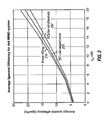
- Three plots are shown in FIG. 2 for three transmission schemes: (1) water-filling power allocation over all transmission channels, (2) selective channel inversion applied to all transmission channels (SCI-for-all-channels), and (3) selective channel inversion applied to each eigenmode independently (SCI-per-eigenmode) with the total transmit power being distributed among the four groups using water-filling based on their average channel SNRs.
- FIG. 2 indicates that the water-filling power allocation (plot 210) yields the highest spectral efficiency, as expected.
- the performance of the SCI-for-all-channels scheme (plot 230) is approximately 2.5 dB worse than that of the optimal water-filling scheme at a spectral efficiency of 15 bps/Hz.
- the SCI-for-all channels scheme results in much lower complexity for both the transmitter and receiver since a single data rate and a common coding/modulation scheme may be used for all selected transmission channels.
- the performance of the SCI-per-eigenmode scheme (plot 220) is approximately 1.5 dB worse than that of the water-filling scheme and 1.0 dB better than that of the SCI-for-all-channels scheme at 15 bps/Hz spectral efficiency. This result is expected since the SCI-per-eigenmode scheme combines water-filling with selective channel inversion. Although the SCI-per-eigenmode scheme is more complex than the SCI-for-all-channels scheme, it is less complex than the water-filling scheme and achieves comparable performance.
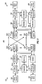
- FIG. 3 is a block diagram of an embodiment of an access point 310 and a user terminal 350 in a MIMO-OFDM system 300.
- traffic data i.e., information bits
- TX transmit
- a TX MIMO processor 320 further processes the modulation symbols to provide preconditioned symbols, which are then multiplexed with pilot data and provided to N T modulators (MOD) 322a through 322t, one for each transmit antenna.
- Each modulator 322 processes a respective stream of preconditioned symbols to generate a modulated signal, which is then transmitted via a respective antenna 324.
- the modulated signals transmitted from the N T antennas 324a through 324t are received by N R antennas 352a through 352r.
- the received signal from each antenna 352 is provided to a respective demodulator (DEMOD) 354.
- Each demodulator 354 conditions (e.g., filters, amplifies, and frequency downconverts) and digitizes the received signal to provide a stream of samples, and further processes the samples to provide a stream of received symbols.
- An RX MIMO processor 360 then processes the N R received symbol streams to provide N T streams of recovered symbols, which are estimates of the modulation symbols sent by the access point.
- the processing for the reverse path from the user terminal to the access point may be similar to, or different from, the processing for the forward path.
- the reverse path may be used to send channel state information (CSI) from the user terminal back to the access point.
- CSI channel state information
- the CSI is used at the access point to select the proper coding and modulation schemes for use and to perform the selective channel inversion.
- Controllers 330 and 370 direct the operation at the access point and user terminal, respectively.
- Memories 332 and 372 provide storage for program codes and data used by controllers 330 and 370, respectively.
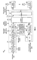
- FIG. 4 is a block diagram of an embodiment of a transmitter unit 400, which is an embodiment of the transmitter portion of access point 310 in FIG. 3. Transmitter unit 400 may also be used for user terminal 350.
- an encoder/puncturer 412 receives and codes the traffic data (i.e., the information bits) in accordance with one or more coding schemes to provide coded bits.
- a channel interleaver 414 then interleaves the coded bits based on one or more interleaving schemes to provide a combination of time, spatial, and/or frequency diversity.
- a symbol mapping element 416 then maps the interleaved data in accordance with one or more modulation schemes (e.g., QPSK, M-PSK, M-QAM, and so on) to provide modulation symbols.
- the coding and modulation for the N S groups may be performed in various manners.
- a separate coding and modulation scheme is used for each group of transmission channels for which selective channel inversion is applied.
- a separate set of encoder, interleaver, and symbol mapping element may be used for each group.
- a common coding scheme is used for all groups, followed by a variable-rate puncturer and a separate modulation scheme for each group. This embodiment reduces hardware complexity at both the transmitter and the receiver.
- trellis coding and Turbo coding may also be used to code the information bits.
- estimates of the impulse response of the MIMO channel are provided to a fast Fourier transform (FFT) unit 422 as a sequence of matrices of time-domain samples, ( n ).
- FFT unit 422 then performs an FFT on each set of N F matrices ( n ) to provide a corresponding set of N F estimated channel frequency response matrices, ⁇ ( k ) for k ⁇ ⁇ 1, ..., N F ⁇ .
- a unit 424 then performs eigenvalue decomposition on each matrix ⁇ (k) to provide the unitary matrix E ( k ) and the diagonal matrix D (k), as described above.
- the diagonal matrices D ( k ) are provided to a power allocation unit 430 and the unitary matrices E (k) are provided to a spatial processor 450.
- Power allocation unit 430 distributes the total transmit power P total to the N S groups using any one of the group power allocation schemes described above. This results in power allocations of P G (i) , for i ⁇ ⁇ 1, ..., N s ⁇ , for the N s groups. Unit 430 then performs selective channel inversion independently for each group based on that group's allocated transmit power P G ( i ). This results in power allocations of P i ( k ), for k ⁇ ⁇ 1,.... N F ⁇ , for the N F frequency bins in each group, where P i (k) may be equal to zero for one or more bins in the group (if it is not required that any active eigenmode be complete eigenmode). Unit 432 performs water-filling to distribute the total transmit power, and unit 434 performs selective channel inversion for each group. The power allocations P i (k) for all transmission channels are provided to a signal scaling unit 440.
- Unit 440 receives and scales the modulation symbols based on the power allocations to provide scaled modulation symbols.
- a multiplexer (MUX) 452 receives and multiplexes pilot data with the preconditioned symbols.
- the pilot data may be transmitted on all or a subset of the transmission channels, and is used at the receiver to estimate the MIMO channel.
- Multiplexer 452 provides one stream of preconditioned symbols to each OFDM modulator 322.
- an IFFT unit receives the preconditioned symbol stream and performs an inverse FFT on each set of N F symbols for the N F frequency bins to obtain a corresponding time-domain representation, which is referred to as an OFDM symbol.
- a cyclic prefix generator repeats a portion of the OFDM symbol to form a corresponding transmission symbol. The cyclic prefix ensures that the transmission symbol retains its orthogonal properties in the presence of multipath delay spread.
- a transmitter unit then converts the transmission symbols into one or more analog signals and further conditions (e.g., amplifies, filters, and frequency upconverts) the analog signals to generate a modulated signal that is then transmitted from the associated antenna 324.
- FIG. 5 is a flow diagram of an embodiment of a process 500 for processing data using selective channel inversion per eigenmode. Initially, data to be transmitted is coded and modulated based on one or more coding and modulation schemes (step 512).
- the available transmission channels are arranged into a number of groups, where each group may include all frequency bins for a given eigenmode (step 514). (Each group may also be defined to include frequency bins for multiple eigenmodes, or only a subset of the frequency bins for a single eigenmode.)
- the total transmit power is then allocated to the groups using a particular group power allocation scheme (step 516).
- Selective channel inversion is then performed independently for each group. For each group selected for use (i.e., with non-zero allocated transmit power), one or more frequency bins in the group is selected for use for data transmission based on the transmit power allocated to the group (step 518). Alternatively, all frequency bins in the group may be selected if the group is to be used. A scaling factor is then determined for each selected frequency bin such that all selected frequency bins for each group have similar received signal quality, which may be quantified by received SNR, received power, or some other measure (step 520).
- Each modulation symbol is then scaled by the scaling factor for the frequency bin to be used to transmit that modulation symbol (step 522).
- the scaled modulation symbols may further be preconditioned to diagonalize the MIMO channel (step 524).
- the preconditioned symbols are further processed and transmitted.
- the selective channel inversion may be performed at the transmitter based on the estimated channel response matrix ⁇ ( k ), as described above.
- the selective channel inversion may also be performed at the receiver based on the channel gains, the received SNRs, or some other measure of received signal quality.
- the transmitter is provided with sufficient channel state information (CSI), in whatever form, such that it is able to determine (1) the particular data rate and coding and modulation scheme to use for each eigenmode and (2) the transmit power (or scaling factor) to use for each selected transmission channel such that the channels in each group have similar signal quality at the receiver (i.e., to invert the selected transmission channels).
- CSI channel state information
- a group may be defined to include the frequency bins for multiple eigenmodes, or only some of the frequency bins for one or more eigenmodes, and so on.
- ASICs application specific integrated circuits
- DSPs digital signal processors
- DSPDs digital signal processing devices
- PLDs programmable logic devices
- FPGAs field programmable gate arrays
- the techniques described herein may be implemented with modules (e.g., procedures, functions, and so on) that perform the functions described herein.
- the software codes may be stored in a memory unit (e.g., memory 332 or 372 in FIG. 3) and executed by a processor (e.g., controller 330 or 370).
- the memory unit may be implemented within the processor or external to the processor, in which case it can be communicatively coupled to the processor via various means as is known in the art.
Description
- The present invention relates generally to data communication, and more specifically to techniques for performing selective channel inversion per eigenmode for MIMO systems.
- A multiple-input multiple-output (MIMO) communication system employs multiple (N T ) transmit antennas and multiple (N R ) receive antennas for data transmission. A MIMO channel formed by the N T transmit and N R receive antennas may be decomposed into N S independent channels, with N S ≤ min {N T , N R }. Each of the N s independent channels is also referred to as a spatial subchannel or eigenmode of the MIMO channel. Such a system is, for example, described in
EP 1 117 197 A2. - The spatial subchannels of a wideband MIMO system may encounter different channel conditions due to various factors such as fading and multipath. Each spatial subchannel may thus experience frequency selective fading, which is characterized by different channel gains at different frequencies of the overall system bandwidth. Assuming no power control, this then results in different signal-to-noise-and-interference ratios (SNRs) at different frequencies of each spatial subchannel, which would then be able to support different data rates for a particular level of performance (e.g., 1% packet error rate).
- To combat frequency selective fading in a wideband channel, orthogonal frequency division multiplexing (OFDM) may be used to effectively partition the overall system bandwidth into a number of (N F ) subbands, which are also referred to as frequency bins or subchannels. With OFDM, each subband is associated with a respective subcarrier upon which data may be modulated. For a MIMO system that utilizes OFDM (i.e., a MIMO-OFDM system), each subband of each spatial subchannel may be-viewed as an independent transmission channel.
- A key challenge in a coded communication system is the selection of the appropriate data rates and coding and modulation schemes to use for a data transmission based on the channel conditions. A major goal for the system is to maximize spectral efficiency while reducing complexity for both the transmitter and receiver.
- One straightforward technique for selecting data rates and coding and modulation schemes is to "bit load" each transmission channel in the system according to its transmission capability. However, this technique has several major drawbacks. First, coding and modulating individually for each transmission channel can significantly increase the complexity of the processing at both the transmitter and receiver. Second, coding individually for each transmission channel may greatly increase coding and decoding delay.
- There is, therefore, a need in the art for techniques to achieve high spectral efficiency in MIMO systems without having to individually code for each transmission channel.
- Techniques are provided herein to perform selective channel inversion per eigenmode in a MIMO system to achieve high spectral efficiency while reducing complexity at both the transmitter and receiver. The available transmission channels are arranged into a number of groups, where each group may include all transmission channels (or frequency bins) for an eigenmode of a MIMO channel. The total transmit power is allocated to the groups using a particular power allocation scheme (e.g., uniform power allocation, water-filling, and so on). Selective channel inversion is then performed independently for each group selected for use for data transmission (i.e., with non-zero allocated transmit power). For each such group, one or more transmission channels in the group is selected for use, and a scaling factor is determined for each selected channel such that all selected channels for the group are inverted and achieve similar received signal quality (e.g., received SNR).
- Various aspects and embodiments of the invention are described in further detail below. The invention further provides methods, program codes, digital signal processors, transmitter units, receiver units, and other apparatuses and elements that implement various aspects, embodiments, and features of the invention, as described in further detail below.
- The features, nature, and advantages of the present invention will become more apparent from the detailed description set forth below when taken in conjunction with the drawings in which like reference characters identify correspondingly throughout and wherein:
- FIG. 1 graphically illustrates eigenvalue decomposition for a MIMO-OFDM system;
- FIG. 2 shows plots of the average spectral efficiency achieved by three transmission schemes for an example 4×4 MIMO system;
- FIG. 3 is a block diagram of an access point and a user terminal in the MIMO-OFDM system;
- FIG. 4 is a block diagram of a transmitter unit in the access point; and
- FIG. 5 is a flow diagram for processing data using selective channel inversion per eigenmode.
- In a MIMO communication system, such as a multiple-antenna wireless communication system, the data streams transmitted from the N T transmit antennas interfere with each other at the receiver. One technique for combating this interference is to "diagonalize" the MIMO channel to obtain a number of independent channels.
- The model for a MIMO system may be expressed as:

where - y
- is a vector with N R entries, {y i} for i ∈ {1, ..., N R } , for the symbols received by the N R receive antennas (i.e., the "received" vector);
- x
- is a vector with N T entries, {x j } for j ∈ {1, ..., N T }, for the symbols transmitted from the N T transmit antennas (i.e., the "transmitted" vector);
- H
- is an (N R ×N T ) channel response matrix that contains the transfer functions (i.e., complex gains) from the N T transmit antennas to the N R receive antennas; and
- n
- is additive white Gaussian noise (AWGN) with a mean vector of 0 and a covariance matrix of Λ n = σ2 I , where 0 is a vector of all zeros, I is the identity matrix with ones along the diagonal and zeros everywhere else, and σ2 is the noise variance.
- For simplicity, a flat-fading, narrowband channel is assumed. In this case, the channel response can be represented by a constant complex value for the entire system bandwidth, and the elements of the channel response matrix H are scalars. Although the assumption of frequency non-selectivity is assumed here for simplicity, the techniques described herein may be extended for frequency selective channels.
- The channel response matrix H may be diagonalized by performing eigenvalue decomposition on the correlation matrix of H, which is R = H H H. The eigenvalue decomposition of the (N T × N T ) correlation matrix R may be expressed as:

where - E
- is an (N T ×N T ) unitary matrix whose columns are the eigenvectors e i of R , for i ∈ {1,...,N T };
- D
- is an (N T × N T ) diagonal matrix with entries on the diagonal corresponding to the eigenvalues of R ; and
- The eigenvalue decomposition may also be performed using singular value decomposition (SVD), which is known in the art.
- The diagonal matrix D contains non-negative real values along the diagonal and zeros elsewhere. These diagonal entries are referred to as the eigenvalues of the matrix R and are indicative of the power gains for the independent channels of the MIMO channel. The number of independent channels for a MIMO system with N T transmit and N R receive antennas is the number of non-zero eigenvalues of R, N s ≤ min {N T , N R }. These non-zero eigenvalues are denoted as {λ i }, for i = {1,...,N s}.
- Without taking into account power constraints for the N T transmit antennas, the MIMO channel may be diagonalized by pre-multiplying (or "preconditioning") a "data" vector s with the unitary matrix E to obtain the transmitted vector x . The preconditioning at the transmitter may be expressed as:

- At the receiver, the received vector y may be pre-multiplied (or "conditioned") with E H H H to obtain an estimate of the data vector s . The conditioning to obtain the data vector estimate ŝ may be expressed as:

where n̂ is AWGN with a mean vector of 0 and a covariance matrix of Λ n̂ = σ 2 D . - As shown in equation (4), the preconditioning at the transmitter and the conditioning at the receiver result in the data vector s being transformed by an effective channel response represented by the matrix D , as well as a scaling of the noise elements. Since D is a diagonal matrix, there are effectively N S non-interfering, parallel channels. Each of these channels has a power gain equal to the square of the corresponding eigenvalue, λ i 2, and a noise power equal to σ2λ i for i ∈ {1, ..., N s }, yielding a signal-to-noise ratio of λ i /σ2. Thus, the power gain of each of these channels is equal to the eigenvalue, λ i , for i ∈ {1,..., N s }. Parallel channel i is often referred to as eigenmode i or mode i. The diagonalization of the MIMO channel as shown in equations (3) and (4) can be achieved if the transmitter is provided with the channel response matrix H or equivalent information.
- The eigenvalue decomposition described above may also be performed for a wideband, frequency-selective channel. For a MIMO-OFDM system, the wideband channel is divided into N F flat-fading, orthogonal frequency bins or subbands. The eigenvalue decomposition may then be performed independently for the channel response matrix H(k) for each frequency bin, k, to determine the N S spatial subchannels or eigenmodes for that frequency bin. Each spatial subchannel of each frequency bin is also referred to as a "transmission" channel.
- The model for a MIMO-OFDM system may be expressed as:

where "(k)" denotes the k-th frequency bin. - The eigenvalue decomposition of the correlation matrix R(k) for each frequency bin may be expressed as:

The non-zero eigenvalues for R(k) are denoted as {λ i (k)}, for i = {1, ..., N s } and k = {1, ..., N F } . Thus, for the MIMO-OFDM system, performing eigenmode decomposition for each of the N F frequency bins results in N S spatial subchannels or eigenmodes for each frequency bin, or a total of N S N F transmission channels. - The eigenvalues may be provided in two forms - a "sorted" form and a "random-order" form. In the sorted form, the N S eigenvalues for each frequency bin are sorted in decreasing order so that {λ1(k) ≥ λ2(k) ≥ ... ≥ λ N
S (k)}, where λ1(k) is the largest eigenvalue for frequency bin k and λ NS (k) is the smallest eigenvalue for frequency bin k. In the random-order form, the ordering of the eigenvalues may be random and further independent of frequency. The particular form selected for use, sorted or random-ordered, influences the selection of the eigenmodes for use for data transmission and the coding and modulation scheme to be used for each selected eigenmode, as described below. - FIG. 1 graphically illustrates the eigenvalue decomposition for the MIMO-OFDM system. The set of diagonal matrices, D (k) for k = {1, ..., N F } , is shown arranged in order along an
axis 110 that represents the frequency dimension. The eigenvalues, {λ i (k)} for i = {1, ...,N s }, of each matrix D (k) are located along the diagonal of the matrix. Axis 112 may thus be viewed as representing the spatial dimension. The eigenmode i for all frequency bins (or simply, eigenmode i) is associated with a set of elements, {λ i (k)} for k = {1, ..., N F }, which is indicative of the frequency response across all N F frequency bins for that eigenmode. The set of elements {λ i (k)} for each eigenmode is shown by the shaded boxes along a dashedline 114. Each shaded box in FIG. 1 represents a transmission channel. For each eigenmode that experiences frequency selective fading, the elements {λ i (k)} for that eigenmode may be different for different values of k. - If the eigenvalues in each diagonal matrix D (k) are sorted in descending order, then eigenmode 1 (which is also referred to as the principal eigenmode) would include the largest eigenvalue, λ1(k), in each matrix, and eigenmode N S would include the smallest eigenvalue, λ N
S (k), in each matrix. - The eigenvalue decomposition for each frequency bin in the MIMO-OFDM system results in a total of N S N F eigenvalues for the N S N F transmission channels over the entire bandwidth. Each transmission channel may achieve a different SNR and may be associated with different transmission capability. Various power allocation schemes (or transmission schemes) may be used to distribute the total transmit power to these transmission channels to achieve high overall spectral efficiency, which is given in units of bit/second per Hertz (bps/Hz). Some of these schemes are described in further detail below.
- The "water-filling" or "water-pouring" scheme may be used to optimally distribute the total transmit power across the transmission channels such that the overall spectral efficiency is maximized, under the constraint that the total transmit power at the transmitter is limited to P total . The water-filling scheme distributes power over the N S N F transmission channels such that the channels with increasingly higher SNRs receive increasingly greater fractions of the total transmit power. The transmit power allocated to a given transmission channel is determined by that channel's SNR, which may be given as λ i (k)/σ 2, where λ i (k) is the i-th eigenvalue in the k-th frequency bin.
- The procedure for performing water-filling is known in the art and not described herein. The result of the water-filling is a specific transmit power allocation to each of the N S N F transmission channels, which is denoted as P i (k), for i={1,...,N s} and k = {1, ..., N F }. The power allocation is performed such that the following condition is satisfied:

where L ={1,..., N S } and K={1,..., N F }. - Based on the allocated transmit powers of P i (k), for i = {1,...,N S } and k = {1, ...,N F }, the received SNR, γ i (k), for each transmission channel may be expressed as:

- The total spectral efficiency C for the N S N F transmission channels may then be computed based on a continuous, monotonically increasing logarithmic function for capacity, as follows:

- In a typical communication system, the total range of received SNRs expected to be observed may be partitioned into a number of sub-ranges. Each subrange may then be associated with a particular coding and modulation scheme chosen to yield the highest spectral efficiency for a given bit error rate (BER), frame error rate (FER), or packet error rate (PER). The water-filling power allocation may result in a different received SNR for each of the N S N F transmission channels. This would then result in the use of many different coding/modulation schemes for the transmission channels. The coding/modulation per transmission channel increases the overall spectral efficiency at the expense of greater complexity for both the transmitter and receiver.
- The "SCI-for-all-channels" scheme performs selective channel inversion (SCI) on all transmission channels such that those selected for use achieve approximately equal received SNRs at the receiver. This would then allow a common coding and modulation scheme to be used for all selected transmission channels. This scheme greatly reduces complexity for both the transmitter and receiver in comparison to the water-filling scheme. The equalization of the received SNRs may be achieved by first selecting all or only a subset of the N S N F available transmission channels for use for data transmission. The channel selection may result in the elimination of poor channels with low SNRs. The total transmit power P total is then distributed across the selected transmission channels in such a way that the received SNR is approximately equal for all selected transmission channels.
- If "full" channel inversion is performed for all N S N F available transmission channels, then the total transmit power P total may be allocated such that approximately equal signal power is received for all these channels. An appropriate amount of transmit power P i (k) to allocate to eigenmode i of frequency bin k may be expressed as:

where α is a normalization factor used to distribute the total transmit power among the available transmission channels. This normalization factor, α, may be expressed as:
- The normalization factor, α, ensures approximately equal received signal power for all transmission channels, which is given as αP total . The total transmit power is thus effectively distributed (unevenly) across all available transmission channels based on their channel power gains, which is given by the eigenvalues λ i (k).
- If "selective" channel inversion is performed, then only transmission channels whose received powers are at or above a particular threshold β relative to the total received power are selected for use for data transmission. Transmission channels whose received powers fall below this threshold are discarded and not used. For each selected transmission channel, the transmit power to be allocated to the channel is determined as described above, such that all selected transmission channels are received at approximately equal power levels. The threshold β may be selected to maximize spectral efficiency or based on some other criterion.
- The selection of the transmission channels for use may be performed as follows. Initially, an average power gain P avg is computed for all available transmission channels and may be expressed as:

- The transmit power to allocate to each transmission channel may then be expressed as:

where β is the threshold and α̃ is a normalization factor that is similar to α in equation (11). However, the normalization factor α̃ is computed over only the selected transmission channels and may be expressed as:
The threshold β may be derived as described below (in Section 3.2). - As shown in equation (13), a transmission channel is selected for use if its eigenvalue (or channel power gain) is greater than or equal to a power threshold (i.e., λ i (k) ≥ βP avg ). Since the normalization factor α̃ is computed based only on the selected transmission channels, the total transmit power P total is distributed to the selected transmission channels based on their channel gains such that all selected transmission channels have approximately equal received power, which may be expressed as α̃P total .
- The equalization of the received SNRs for all selected transmission channels can thus be achieved by non-uniform distribution of the total transmit power across these channels. The approximately equal received SNRs would then allow the use of a single data rate and a common coding/modulation scheme for all selected transmission channels, which would greatly reduce complexity.
- The "SCI-per-eigenmode" scheme performs selective channel inversion independently for each eigenmode to provide improved performance. In an embodiment, the N S N F transmission channels are arranged into N S groups such that each group includes all N F frequency bins for a given eigenmode (i.e., group i includes the spatial subchannels for all N F frequency bins for eigenmode i). There is thus one group for each eigenmode.
- The SCI-per-eigenmode scheme includes two steps. In the first step, the total transmit power P total is distributed to the N S groups based on a particular group power allocation scheme. In the second step, selective channel inversion is performed independently for each group to distribute that group's allocated transmit power to the N F frequency bins in the group. Each of these steps is described in further detail below.
- The total transmit power P total may be distributed to the N S groups in various manners, some of which are described below.
- In a first embodiment, the total transmit power P total is distributed uniformly across all N S groups such that they are all allocated equal power. The transmit power P G (i) allocated to each group may be expressed as:

- In a second embodiment, the total transmit power P total is distributed to the N s groups based on water-filling across all available transmission channels. For this embodiment, the total transmit power, P total , is first distributed to all N S N F transmission channels using water-filling, as described above. Each transmission channel is allocated P i (k), for i ∈ {1,...,N s } and k = {1, ..., N F }. The transmit power allocated to each group can then be determined by summing over the transmit powers allocated to the N F transmission channels in that group. The transmit power allocated to group i may be expressed as:

- In a third embodiment, the total transmit power P total is distributed to the N S groups based on water-filling across all groups using their average channel SNRs. Initially, the average channel SNR, γ avg (i), for each group is determined as:

Water-filling is then performed to distribute the total transmit power P total across the N S groups based on their average channel SNRs. The transmit power allocated to each of the N s groups is denoted as P G (i) , for i ∈ {1,..., N s}. - In a fourth embodiment, the total transmit power P total is distributed to the N S groups based on water-filling across all groups using the received SNRs of the transmission channels after channel inversion. For this embodiment, the total transmit power P total is first distributed uniformly to the N S groups as shown above in equation (15) such that each group is allocated an initial transmit power of P̃ G (i) = P total /N s , for i ∈ {1, ..., N s} . Selective channel inversion is then performed independently on each group to determine an initial power allocation, P̃ i (k) for k = {1, ..., N F }, for each frequency bin in the group. The received SNR, γ̃ i (k), for each frequency bin is next determined based on the initial power allocation P̃ i (k), as shown in equation (8). The average received SNR γ̃ avg (i) for each group is then computed as follows:

- The total transmit power P total is then distributed to the N S groups using water-filling based on their average received SNRs, γ̃ avg (i) for i ∈ {1,..., N s }. The results of the water-filling power allocation are revised (i.e., final) transmit power allocations P G (i), for i ∈ {1, ..., N s }, for the N s groups. Selective channel inversion is again performed independently for each group to distribute the group's allocated transmit power P G (i) to the frequency bins in the group. Each frequency bin would then be allocated transmit power P i (k) by the second selective channel inversion.
- The second selective channel inversion need not be performed for a given group if (1) the revised transmit power allocated to the group by the water-filling is greater than the initial uniform power allocation (i.e., P G (i) > P̃ G (i)) and (2) all frequency bins in the group were selected for use in the initial selective channel inversion. For this specific case, the new power allocation P i (k) for each frequency bin in the group may be expressed as:

Equation (19) may be used because (1) all frequency bins in the group have already been selected for use and no additional frequency bin can be selected even though the revised power allocation P G (i) for the group is higher than the initial power allocation P̃ G (i), and (2) the initial selective channel inversion already determines the proper distribution of power to the frequency bins in the group to achieve approximately equal received SNRs for these channels. In all other cases, the selective channel inversion is performed again for each group to determine the transmit power allocations, P i (k) for k ∈ {1,..., N F }, for the frequency bins in the group. - Once the total transmit power P total has been distributed to the N S groups using any one of the group power allocation schemes described above, selective channel inversion is performed independently for each of the N S groups and on the N F frequency bins within each group. The selective channel inversion for each group may be performed as follows.
- Initially, the average power gain, P avg (i), for each group is determined as:

The transmit power allocated to frequency bin k in group i may then be expressed as:
where β i is the threshold and α̃ i is the normalization factor for group i. The normalization factor α̃ i for each group is computed over only the selected transmission channels for that group, and may be expressed as:
The summation of the inverse channel power gains in equation (22) takes into account the channel power gains over all selected frequency bins of group i. - The threshold β i to select frequency bins for use in each group may be set based on various criteria, e.g., to optimize spectral efficiency. In one embodiment, the threshold β i is set based on the channel power gains (or eigenvalues) and the spectral efficiencies of the selected frequency bins based on uniform transmit power allocation across the frequency bins in each group, as described below.
- For this embodiment, the derivation of the threshold β i for group i proceeds as follows (where the derivation is performed independently for each group). Initially, the eigenvalues for all N F frequency bins in the group are ranked and placed in a list G i (λ) , for λ ∈ {1, ..., N F } , in descending order such that G i (1) = max {λ i (k)} and G i (N F ) = min {λ i (k) for i ∈ {1, ..., N s }.
- For each λ, where λ ∈ {1, ..., N F } , the spectral efficiency for the λ best frequency bins is computed, where "best" refers to the frequency bins with the highest power gains, G i (λ). This can be achieved as follows. First, the total transmit power available to the group, P G (i), is distributed to the λ best frequency bins using any one of the power allocation schemes described above. For simplicity, the uniform power allocation scheme is used, and the transmit power for each of the λ frequency bins is P G (i)/λ. Next, the received SNR for each of the λ frequency bins is computed as:

- The spectral efficiency C i (λ) for the λ best frequency bins in group i is then computed as:

where ρ is a scale factor used to account for inefficiencies in the coding and modulation scheme selected for use. - The spectral efficiency C i (λ) is computed for each value of λ, where λ ∈ {1, ..., N F }, and stored in an array. After all N F values of C i (λ) have been computed for the N F possible combinations of selected frequency bins, the array of spectral efficiencies is traversed and the largest value of C i (λ) is determined. The value of λ, λmax, corresponding to the largest C i (λ) is then the number of frequency bins that results in the maximum spectral efficiency for the channel conditions being evaluated and using uniform transmit power allocation.
- Since the eigenvalues for the N F frequency bins in group i are ranked in decreasing order in the list G i (λ), the spectral efficiency increases as more frequency bins are selected for use until the optimal point is reached, after which the spectral efficiency decreases because more of the group's transmit power is allocated to poorer frequency bins. Thus, instead of computing the spectral efficiency C i (λ) for all possible values of λ, the spectral efficiency C i (λ) for each new value of λ may be compared against the spectral efficiency C i (λ-1) for the previous value of λ. The computation may then be terminated if the optimal spectral efficiency is reached, which is indicated by C i (λ) < C i (λ-1).
- The threshold β i may then be expressed as:

where P avg (i) is determined as shown in equation (20). - The threshold β i may also be set based on some other criterion or some other power allocation scheme (instead of uniform allocation).
- Selective channel inversion is described in further detail in U.S. Patent Application Serial No. 09/860,274, filed May 17, 2001, Serial No. 09/881,610, filed June 14, 2001, and Serial No. 09/892,379, filed June 26, 2001, all three entitled "Method and Apparatus for Processing Data for Transmission in a Multi-Channel Communication System Using Selective Channel Inversion," assigned to the assignee of the present application.
- Performing selective channel inversion independently for each group results in a set of transmit power allocations, P i (k) for k ∈ {1, ..., N F }, for the N F frequency bins in each group. The selective channel inversion may result in less than N F frequency bins being selected for use for any given group. The unselected frequency bins would be allocated no transmit power (i.e., P i (k) = 0 for these bins). The power allocations for the selected frequency bins are such that these bins achieve approximately equal received SNRs. This then allows a single data rate and a common coding/modulation scheme to be used for all selected frequency bins in each group.
- For the sorted form, the eigenvalues λ i (k), for i ∈ {1, ..., N s }, for each diagonal matrix D (k) are sorted such that the diagonal elements with smaller indices are generally larger.
Eigenmode 1 would then be associated with the largest eigenvalue in each of the N F diagonal matrices,eigenmode 2 would be associated with the second largest eigenvalue, and so on. For the sorted form, even though the channel inversion is performed over all N F frequency bins for each eigenmode, the eigenmodes with lower indices are not likely to have too many bad frequency bins (if any) and excessive transmit power is not used for bad bins. - If water-filling is used to distribute the total transmit power to the N S eigenmodes, then the number of eigenmodes selected for use may be reduced at low SNRs. The sorted form thus has the advantage that at low SNRs, the coding and modulation are further simplified through the reduction in the number of eigenmodes selected for use.
- For the random-ordered form, the eigenvalues for each diagonal matrix D (k) are randomly ordered. This may result in a smaller variation in the average received SNRs for all of the eigenmodes. In this case, fewer than N S common coding and modulation schemes may be used for the N S eigenmodes.
- In one transmission scheme, if a group is to be used for data transmission, then all N F frequency bins in that group are selected (i.e., any active eigenmode needs to be a complete eigenmode). The frequency selective nature of an eigenmode can be exaggerated if one or more frequency bins are omitted from use. This greater frequency selective fading can cause higher level of inter-symbol interference (ISI), which is a phenomenon whereby each symbol in a received signal acts as distortion to subsequent symbols in the received signal. Equalization may* then be required at the receiver to mitigate the deleterious effects of ISI distortion. This equalization may be avoided by performing full channel inversion on all frequency bins of each eigenmode that is selected for use. This transmission scheme may be advantageously used in conjunction with the sorted form and the water-filling power allocation since, as noted above, the eigenmodes with lower indices are not likely to have too many bad frequency bins.
- FIG. 2 shows plots of the average spectral efficiency achieved by three transmission schemes for an example 4×4 MIMO system with total transmit power of P total = 4. Three plots are shown in FIG. 2 for three transmission schemes: (1) water-filling power allocation over all transmission channels, (2) selective channel inversion applied to all transmission channels (SCI-for-all-channels), and (3) selective channel inversion applied to each eigenmode independently (SCI-per-eigenmode) with the total transmit power being distributed among the four groups using water-filling based on their average channel SNRs.
- The average spectral efficiency is plotted versus operating SNR, which is defined as γ op =1/σ2. FIG. 2 indicates that the water-filling power allocation (plot 210) yields the highest spectral efficiency, as expected. The performance of the SCI-for-all-channels scheme (plot 230) is approximately 2.5 dB worse than that of the optimal water-filling scheme at a spectral efficiency of 15 bps/Hz. However, the SCI-for-all channels scheme results in much lower complexity for both the transmitter and receiver since a single data rate and a common coding/modulation scheme may be used for all selected transmission channels. The performance of the SCI-per-eigenmode scheme (plot 220) is approximately 1.5 dB worse than that of the water-filling scheme and 1.0 dB better than that of the SCI-for-all-channels scheme at 15 bps/Hz spectral efficiency. This result is expected since the SCI-per-eigenmode scheme combines water-filling with selective channel inversion. Although the SCI-per-eigenmode scheme is more complex than the SCI-for-all-channels scheme, it is less complex than the water-filling scheme and achieves comparable performance.
- FIG. 3 is a block diagram of an embodiment of an
access point 310 and auser terminal 350 in a MIMO-OFDM system 300. - At
access point 310, traffic data (i.e., information bits) from adata source 312 is provided to a transmit (TX)data processor 314, which codes, interleaves, and modulates the data to provide modulation symbols. ATX MIMO processor 320 further processes the modulation symbols to provide preconditioned symbols, which are then multiplexed with pilot data and provided to N T modulators (MOD) 322a through 322t, one for each transmit antenna. Each modulator 322 processes a respective stream of preconditioned symbols to generate a modulated signal, which is then transmitted via a respective antenna 324. - At
user terminal 350, the modulated signals transmitted from the N T antennas 324a through 324t are received by N R antennas 352a through 352r. The received signal from each antenna 352 is provided to a respective demodulator (DEMOD) 354. Each demodulator 354 conditions (e.g., filters, amplifies, and frequency downconverts) and digitizes the received signal to provide a stream of samples, and further processes the samples to provide a stream of received symbols. AnRX MIMO processor 360 then processes the N R received symbol streams to provide N T streams of recovered symbols, which are estimates of the modulation symbols sent by the access point. - The processing for the reverse path from the user terminal to the access point may be similar to, or different from, the processing for the forward path. The reverse path may be used to send channel state information (CSI) from the user terminal back to the access point. The CSI is used at the access point to select the proper coding and modulation schemes for use and to perform the selective channel inversion.
-
Controllers Memories controllers - FIG. 4 is a block diagram of an embodiment of a
transmitter unit 400, which is an embodiment of the transmitter portion ofaccess point 310 in FIG. 3.Transmitter unit 400 may also be used foruser terminal 350. - Within
TX data processor 314, an encoder/puncturer 412 receives and codes the traffic data (i.e., the information bits) in accordance with one or more coding schemes to provide coded bits. Achannel interleaver 414 then interleaves the coded bits based on one or more interleaving schemes to provide a combination of time, spatial, and/or frequency diversity. Asymbol mapping element 416 then maps the interleaved data in accordance with one or more modulation schemes (e.g., QPSK, M-PSK, M-QAM, and so on) to provide modulation symbols. - The coding and modulation for the N S groups may be performed in various manners. In one embodiment, a separate coding and modulation scheme is used for each group of transmission channels for which selective channel inversion is applied. For this embodiment, a separate set of encoder, interleaver, and symbol mapping element may be used for each group. In another embodiment, a common coding scheme is used for all groups, followed by a variable-rate puncturer and a separate modulation scheme for each group. This embodiment reduces hardware complexity at both the transmitter and the receiver. In other embodiments, trellis coding and Turbo coding may also be used to code the information bits.
- Within
TX MIMO processor 320, estimates of the impulse response of the MIMO channel are provided to a fast Fourier transform (FFT)unit 422 as a sequence of matrices of time-domain samples,(n).
FFT unit 422 then performs an FFT on each set of N F matrices(n) to provide a corresponding set of N F estimated channel frequency response matrices, Ĥ (k) for k ∈ {1, ..., N F }. - A
unit 424 then performs eigenvalue decomposition on each matrix Ĥ (k) to provide the unitary matrix E (k) and the diagonal matrix D (k), as described above. The diagonal matrices D (k) are provided to apower allocation unit 430 and the unitary matrices E (k) are provided to aspatial processor 450. -
Power allocation unit 430 distributes the total transmit power P total to the N S groups using any one of the group power allocation schemes described above. This results in power allocations of P G (i), for i ∈ {1, ..., N s}, for the N s groups.Unit 430 then performs selective channel inversion independently for each group based on that group's allocated transmit power P G (i). This results in power allocations of P i (k), for k ∈ {1,.... N F }, for the N F frequency bins in each group, where P i (k) may be equal to zero for one or more bins in the group (if it is not required that any active eigenmode be complete eigenmode).Unit 432 performs water-filling to distribute the total transmit power, andunit 434 performs selective channel inversion for each group. The power allocations P i (k) for all transmission channels are provided to asignal scaling unit 440. -
Unit 440 receives and scales the modulation symbols based on the power allocations to provide scaled modulation symbols. The signal scaling for each modulation symbol may be expressed as:
where s i (k) is the modulation symbol to be transmitted on eigenmode i of frequency bin k,

- A
spatial processor 450 then preconditions the scaled modulation symbols based on the unitary matrices E (k) to provide preconditioned symbols, as follows:
where s̃(k) = [s 1 (k) s 2 (k) .. S NT (k)] T , x (k) = [x 1(k) x 2(k) .. x NT (k)] T , and x i (k) is the preconditioned symbol to be sent on frequency bin k of transmit antenna i. If N S < N T , then s̃ (k) would include N S none-zero entries and the remaining N T - N S entries would be zero. - A multiplexer (MUX) 452 receives and multiplexes pilot data with the preconditioned symbols. The pilot data may be transmitted on all or a subset of the transmission channels, and is used at the receiver to estimate the MIMO channel.
Multiplexer 452 provides one stream of preconditioned symbols to each OFDM modulator 322. - Within each OFDM modulator 322, an IFFT unit receives the preconditioned symbol stream and performs an inverse FFT on each set of N F symbols for the N F frequency bins to obtain a corresponding time-domain representation, which is referred to as an OFDM symbol. For each OFDM symbol, a cyclic prefix generator repeats a portion of the OFDM symbol to form a corresponding transmission symbol. The cyclic prefix ensures that the transmission symbol retains its orthogonal properties in the presence of multipath delay spread. A transmitter unit then converts the transmission symbols into one or more analog signals and further conditions (e.g., amplifies, filters, and frequency upconverts) the analog signals to generate a modulated signal that is then transmitted from the associated antenna 324.
- FIG. 5 is a flow diagram of an embodiment of a
process 500 for processing data using selective channel inversion per eigenmode. Initially, data to be transmitted is coded and modulated based on one or more coding and modulation schemes (step 512). - The available transmission channels are arranged into a number of groups, where each group may include all frequency bins for a given eigenmode (step 514). (Each group may also be defined to include frequency bins for multiple eigenmodes, or only a subset of the frequency bins for a single eigenmode.) The total transmit power is then allocated to the groups using a particular group power allocation scheme (step 516).
- Selective channel inversion is then performed independently for each group. For each group selected for use (i.e., with non-zero allocated transmit power), one or more frequency bins in the group is selected for use for data transmission based on the transmit power allocated to the group (step 518). Alternatively, all frequency bins in the group may be selected if the group is to be used. A scaling factor is then determined for each selected frequency bin such that all selected frequency bins for each group have similar received signal quality, which may be quantified by received SNR, received power, or some other measure (step 520).
- Each modulation symbol is then scaled by the scaling factor for the frequency bin to be used to transmit that modulation symbol (step 522). The scaled modulation symbols may further be preconditioned to diagonalize the MIMO channel (step 524). The preconditioned symbols are further processed and transmitted.
- For clarity, specific embodiments have been described above. Variations to these embodiments and other embodiments may also be derived based on the teachings described herein. For example, it is not necessary to use the SCI-per-eigenmode scheme with spatial processing (i.e., preconditioning) at the transmitter. Other techniques may also be used to diagonalize the MIMO channel without performing preconditioning at the transmitter. Some such techniques are described in U.S. Patent Application Serial No. 09/993,087, entitled "Multiple-Access Multiple-Input Multiple-Output (MIMO) Communication System," filed November 6, 2001, assigned to the assignee of the present application. If spatial processing is not performed at the transmitter, then the selective channel inversion may be applied per transmit antenna or some other group unit.
- The selective channel inversion may be performed at the transmitter based on the estimated channel response matrix Ĥ (k), as described above. The selective channel inversion may also be performed at the receiver based on the channel gains, the received SNRs, or some other measure of received signal quality. In any case, the transmitter is provided with sufficient channel state information (CSI), in whatever form, such that it is able to determine (1) the particular data rate and coding and modulation scheme to use for each eigenmode and (2) the transmit power (or scaling factor) to use for each selected transmission channel such that the channels in each group have similar signal quality at the receiver (i.e., to invert the selected transmission channels).
- The techniques described herein may also be used to perform selective channel inversion on groups that are defined to be something other than single eigenmode. For example, a group may be defined to include the frequency bins for multiple eigenmodes, or only some of the frequency bins for one or more eigenmodes, and so on.
- For clarity, the techniques for performing selective channel inversion per eigenmode have been described specifically for a MIMO-OFDM system. These techniques may also be used for a MIMO system that does not employ OFDM. Moreover, although certain embodiments have been specifically described for the forward link, these techniques may also be applied for the reverse link.
- The techniques described herein may be implemented by various means. For example, these techniques may be implemented in hardware, software, or a combination thereof. For a hardware implementation, the elements used to implement any one or a combination of the techniques may be implemented within one or more application specific integrated circuits (ASICs), digital signal processors (DSPs), digital signal processing devices (DSPDs), programmable logic devices (PLDs), field programmable gate arrays (FPGAs), processors, controllers, micro-controllers, microprocessors, other electronic units designed to perform the functions described herein, or a combination thereof.
- For a software implementation, the techniques described herein may be implemented with modules (e.g., procedures, functions, and so on) that perform the functions described herein. The software codes may be stored in a memory unit (e.g.,
memory controller 330 or 370). The memory unit may be implemented within the processor or external to the processor, in which case it can be communicatively coupled to the processor via various means as is known in the art. - Headings are included herein for reference and to aid in locating certain sections. These headings are not intended to limit the scope of the concepts described therein under, and these concepts may have applicability in other sections throughout the entire specification.
A unitary matrix is denoted by the property E H E = I .
Claims (23)
- A method for processing data for transmission in a multiple-input, multiple-output (MIMO) communication system, characterized in that the method comprises the following steps:arranging a plurality of available transmission channels into a plurality of groups; andfor each group of transmission channels to be used for data transmission,
selecting one or more transmission channels in the group for use, and
determining a scaling factor for each selected transmission channel such that the one or more selected transmission channels in each group have similar received signal quality. - The method of claim 1, wherein each group includes all transmission channels corresponding to a particular eigenmode of a MIMO channel.
- The method of claims 1 or 2, further comprising:allocating total transmit power to the plurality of groups, and wherein the one or more scaling factors for the one or more selected transmission channels in each group are determined based in part on the transmit power allocated to the group.
- The method of claim 3, wherein the total transmit power is uniformly allocated to the plurality of groups.
- The method of claim 3, wherein the total transmit power is allocated to the plurality of groups based on water-filling.
- The method of claim 5, wherein the water-filling is performed across the plurality of available transmission channels, and wherein the transmit power allocated to each group is based on transmit powers allocated to the plurality of transmission channels in the group.
- The method of claim 5, wherein the water-filling is performed based on average signal-to-noise-and-interference ratios (SNRs) for the plurality of groups.
- The method of claim 5, wherein the water-filling is performed based on signal-to-noise-and-interference ratios (SNRs) for the plurality of available transmission channels after channel inversion.
- The method of claim 1, wherein if a group is to be used for data transmission then all transmission channels in the group are selected for the use.
- The method of claim 1, further comprising:coding and modulating data based on one or more coding and modulation schemes to provide modulation symbols; andscaling each modulation symbol based on the scaling factor for the transmission channel used to transmit the modulation symbol.
- The method of claim 10, wherein the data for each group of transmission channels is coded based on a separate coding scheme.
- The method of claim 10, wherein the data for all groups of transmission channels is coded based on a common coding scheme, and wherein coded data for each group is punctured with a rate selected for the group.
- The method of claim 10, further comprising:preconditioning scaled modulation symbols.
- The method of claim 1, wherein the MIMO system implements orthogonal frequency division multiplexing (OFDM).
- An apparatus for processing data for transmission for use in a multiple-input, multiple-output (MIMO) communication system, characterized in that it comprises:means for arranging a plurality of available transmission channels into a plurality of groups;means for selecting one or more transmission channels in each group for use for data transmission; andmeans for determining a scaling factor for each selected transmission channel such that one or more selected transmission channels in each group have similar received signal quality.
- The apparatus of claim 15, further comprising:means for coding and modulating data based on one or more coding and modulation schemes to provide modulation symbols; andmeans for scaling each modulation symbol based on the scaling factor for the transmission channel used to transmit the modulation symbol.
- The apparatus of any of claims 15 and 16, wherein the apparatus is a transmitter unit.
- The apparatus of claim 17, wherein the transmitter unit comprises a TX MIMO processor operative to select the one or more transmission channels in each group of transmission channels, determine the scaling factor, and scale each modulation symbol based on the scaling factor for the transmission channel used to transmit the modulation symbol.
- The apparatus of claim 18, wherein the TX MIMO processor is further operative to allocate total transmit power to the plurality of groups, and wherein the one or more scaling factors for the one or more selected transmission channels in each group is determined based in part on the transmit power allocated to the group.
- The apparatus of any of claims 17 to 19, wherein the transmitter unit comprises a TX data processor operative to code and modulate data based on one or more coding and modulation schemes to provide modulation symbols.
- The apparatus of any of claims 17 to 20, wherein the multiple-input, multiple-output (MIMO) communication system implements orthogonal frequency division multiplexing (OFDM).
- The apparatus of claim 21, wherein each group includes all transmission channels corresponding to a particular eigenmode of a MIMO channel.
- The transmitter unit of claims 18 or 22, wherein the TX MIMO processor is further operative to precondition scaled modulation symbols.
Applications Claiming Priority (3)
| Application Number | Priority Date | Filing Date | Title |
|---|---|---|---|
| US10/229,209 US8194770B2 (en) | 2002-08-27 | 2002-08-27 | Coded MIMO systems with selective channel inversion applied per eigenmode |
| US229209 | 2002-08-27 | ||
| PCT/US2003/026395 WO2004021634A1 (en) | 2002-08-27 | 2003-08-19 | Coded mimo systems with selective channel inversion applied per eigenmode |
Publications (2)
| Publication Number | Publication Date |
|---|---|
| EP1532762A1 EP1532762A1 (en) | 2005-05-25 |
| EP1532762B1 true EP1532762B1 (en) | 2006-12-06 |
Family
ID=31976188
Family Applications (1)
| Application Number | Title | Priority Date | Filing Date |
|---|---|---|---|
| EP03791732A Expired - Fee Related EP1532762B1 (en) | 2002-08-27 | 2003-08-19 | Coded mimo systems with selective channel inversion applied per eigenmode |
Country Status (16)
| Country | Link |
|---|---|
| US (1) | US8194770B2 (en) |
| EP (1) | EP1532762B1 (en) |
| JP (1) | JP4386836B2 (en) |
| KR (1) | KR100983231B1 (en) |
| CN (1) | CN100370721C (en) |
| AU (1) | AU2003265601B2 (en) |
| BR (1) | BR0313819A (en) |
| CA (1) | CA2496619A1 (en) |
| DE (1) | DE60310237T2 (en) |
| HK (1) | HK1083283A1 (en) |
| IL (1) | IL166579A0 (en) |
| MX (1) | MXPA05002229A (en) |
| RU (1) | RU2328074C2 (en) |
| TW (1) | TWI324862B (en) |
| UA (1) | UA84684C2 (en) |
| WO (1) | WO2004021634A1 (en) |
Families Citing this family (113)
| Publication number | Priority date | Publication date | Assignee | Title |
|---|---|---|---|---|
| US6956907B2 (en) * | 2001-10-15 | 2005-10-18 | Qualcomm, Incorporated | Method and apparatus for determining power allocation in a MIMO communication system |
| US20040081131A1 (en) | 2002-10-25 | 2004-04-29 | Walton Jay Rod | OFDM communication system with multiple OFDM symbol sizes |
| US8169944B2 (en) * | 2002-10-25 | 2012-05-01 | Qualcomm Incorporated | Random access for wireless multiple-access communication systems |
| US8570988B2 (en) * | 2002-10-25 | 2013-10-29 | Qualcomm Incorporated | Channel calibration for a time division duplexed communication system |
| US8134976B2 (en) * | 2002-10-25 | 2012-03-13 | Qualcomm Incorporated | Channel calibration for a time division duplexed communication system |
| US8320301B2 (en) * | 2002-10-25 | 2012-11-27 | Qualcomm Incorporated | MIMO WLAN system |
| US8218609B2 (en) | 2002-10-25 | 2012-07-10 | Qualcomm Incorporated | Closed-loop rate control for a multi-channel communication system |
| US7002900B2 (en) | 2002-10-25 | 2006-02-21 | Qualcomm Incorporated | Transmit diversity processing for a multi-antenna communication system |
| US8208364B2 (en) * | 2002-10-25 | 2012-06-26 | Qualcomm Incorporated | MIMO system with multiple spatial multiplexing modes |
| US7324429B2 (en) | 2002-10-25 | 2008-01-29 | Qualcomm, Incorporated | Multi-mode terminal in a wireless MIMO system |
| US7986742B2 (en) | 2002-10-25 | 2011-07-26 | Qualcomm Incorporated | Pilots for MIMO communication system |
| US8170513B2 (en) | 2002-10-25 | 2012-05-01 | Qualcomm Incorporated | Data detection and demodulation for wireless communication systems |
| US7206606B2 (en) * | 2002-11-26 | 2007-04-17 | Matsushita Electric Industrial Co., Ltd. | Wireless communication including diversity transmission and reception |
| US7317770B2 (en) * | 2003-02-28 | 2008-01-08 | Nec Laboratories America, Inc. | Near-optimal multiple-input multiple-output (MIMO) channel detection via sequential Monte Carlo |
| US9325532B2 (en) * | 2003-06-30 | 2016-04-26 | Avago Technologies General Ip (Singapore) Pte. Ltd. | Method and apparatus for communicating symbols in a multiple input multiple output communication system using interleaved subcarriers across a plurality of antennas |
| US7245879B2 (en) * | 2003-08-08 | 2007-07-17 | Intel Corporation | Apparatus and associated methods to perform intelligent transmit power control with subcarrier puncturing |
| US7065144B2 (en) * | 2003-08-27 | 2006-06-20 | Qualcomm Incorporated | Frequency-independent spatial processing for wideband MISO and MIMO systems |
| US7742546B2 (en) * | 2003-10-08 | 2010-06-22 | Qualcomm Incorporated | Receiver spatial processing for eigenmode transmission in a MIMO system |
| US8472473B2 (en) | 2003-10-15 | 2013-06-25 | Qualcomm Incorporated | Wireless LAN protocol stack |
| US8842657B2 (en) | 2003-10-15 | 2014-09-23 | Qualcomm Incorporated | High speed media access control with legacy system interoperability |
| US8462817B2 (en) * | 2003-10-15 | 2013-06-11 | Qualcomm Incorporated | Method, apparatus, and system for multiplexing protocol data units |
| US8233462B2 (en) | 2003-10-15 | 2012-07-31 | Qualcomm Incorporated | High speed media access control and direct link protocol |
| US8284752B2 (en) * | 2003-10-15 | 2012-10-09 | Qualcomm Incorporated | Method, apparatus, and system for medium access control |
| US9226308B2 (en) | 2003-10-15 | 2015-12-29 | Qualcomm Incorporated | Method, apparatus, and system for medium access control |
| US8483105B2 (en) * | 2003-10-15 | 2013-07-09 | Qualcomm Incorporated | High speed media access control |
| KR100520159B1 (en) * | 2003-11-12 | 2005-10-10 | 삼성전자주식회사 | Apparatus and method for interference cancellation of ofdm system using multiple antenna |
| KR100996080B1 (en) | 2003-11-19 | 2010-11-22 | 삼성전자주식회사 | Apparatus and method for controlling adaptive modulation and coding in a communication system using orthogonal frequency division multiplexing scheme |
| US9473269B2 (en) * | 2003-12-01 | 2016-10-18 | Qualcomm Incorporated | Method and apparatus for providing an efficient control channel structure in a wireless communication system |
| US7818018B2 (en) * | 2004-01-29 | 2010-10-19 | Qualcomm Incorporated | Distributed hierarchical scheduling in an AD hoc network |
| US8903440B2 (en) * | 2004-01-29 | 2014-12-02 | Qualcomm Incorporated | Distributed hierarchical scheduling in an ad hoc network |
| US7356017B2 (en) | 2004-02-19 | 2008-04-08 | Nokia Corporation | Data loading method, transmitter, and base station |
| US8315271B2 (en) * | 2004-03-26 | 2012-11-20 | Qualcomm Incorporated | Method and apparatus for an ad-hoc wireless communications system |
| US10425134B2 (en) | 2004-04-02 | 2019-09-24 | Rearden, Llc | System and methods for planned evolution and obsolescence of multiuser spectrum |
| US10985811B2 (en) | 2004-04-02 | 2021-04-20 | Rearden, Llc | System and method for distributed antenna wireless communications |
| US9312929B2 (en) | 2004-04-02 | 2016-04-12 | Rearden, Llc | System and methods to compensate for Doppler effects in multi-user (MU) multiple antenna systems (MAS) |
| US9826537B2 (en) | 2004-04-02 | 2017-11-21 | Rearden, Llc | System and method for managing inter-cluster handoff of clients which traverse multiple DIDO clusters |
| US8542763B2 (en) | 2004-04-02 | 2013-09-24 | Rearden, Llc | Systems and methods to coordinate transmissions in distributed wireless systems via user clustering |
| US10200094B2 (en) | 2004-04-02 | 2019-02-05 | Rearden, Llc | Interference management, handoff, power control and link adaptation in distributed-input distributed-output (DIDO) communication systems |
| US10886979B2 (en) | 2004-04-02 | 2021-01-05 | Rearden, Llc | System and method for link adaptation in DIDO multicarrier systems |
| US10187133B2 (en) * | 2004-04-02 | 2019-01-22 | Rearden, Llc | System and method for power control and antenna grouping in a distributed-input-distributed-output (DIDO) network |
| US11309943B2 (en) | 2004-04-02 | 2022-04-19 | Rearden, Llc | System and methods for planned evolution and obsolescence of multiuser spectrum |
| US10749582B2 (en) | 2004-04-02 | 2020-08-18 | Rearden, Llc | Systems and methods to coordinate transmissions in distributed wireless systems via user clustering |
| US11394436B2 (en) | 2004-04-02 | 2022-07-19 | Rearden, Llc | System and method for distributed antenna wireless communications |
| US11451275B2 (en) | 2004-04-02 | 2022-09-20 | Rearden, Llc | System and method for distributed antenna wireless communications |
| US8654815B1 (en) | 2004-04-02 | 2014-02-18 | Rearden, Llc | System and method for distributed antenna wireless communications |
| US9819403B2 (en) | 2004-04-02 | 2017-11-14 | Rearden, Llc | System and method for managing handoff of a client between different distributed-input-distributed-output (DIDO) networks based on detected velocity of the client |
| US10277290B2 (en) | 2004-04-02 | 2019-04-30 | Rearden, Llc | Systems and methods to exploit areas of coherence in wireless systems |
| US7346115B2 (en) * | 2004-04-22 | 2008-03-18 | Qualcomm Incorporated | Iterative eigenvector computation for a MIMO communication system |
| US7564814B2 (en) * | 2004-05-07 | 2009-07-21 | Qualcomm, Incorporated | Transmission mode and rate selection for a wireless communication system |
| JP4604798B2 (en) | 2004-05-10 | 2011-01-05 | ソニー株式会社 | Wireless communication system, wireless communication apparatus, wireless communication method, and computer program |
| US7620096B2 (en) * | 2004-05-25 | 2009-11-17 | New Jersey Institute Of Technology | Equal BER power control for uplink MC-CDMA with MMSE successive interference cancellation |
| US8401018B2 (en) * | 2004-06-02 | 2013-03-19 | Qualcomm Incorporated | Method and apparatus for scheduling in a wireless network |
| US8457152B2 (en) * | 2004-07-16 | 2013-06-04 | Qualcomm Incorporated | Multiple modulation schemes in single rate layering wireless communication systems |
| US9685997B2 (en) | 2007-08-20 | 2017-06-20 | Rearden, Llc | Systems and methods to enhance spatial diversity in distributed-input distributed-output wireless systems |
| US7864659B2 (en) | 2004-08-02 | 2011-01-04 | Interdigital Technology Corporation | Quality control scheme for multiple-input multiple-output (MIMO) orthogonal frequency division multiplexing (OFDM) systems |
| JP5209308B2 (en) | 2004-08-11 | 2013-06-12 | インターデイジタル テクノロジー コーポレーション | Channel sounding to improve system performance |
| JP3754441B1 (en) | 2004-09-10 | 2006-03-15 | 三洋電機株式会社 | Reception method and apparatus, and communication system using the same |
| CN101065913B (en) * | 2004-11-17 | 2011-08-10 | 皇家飞利浦电子股份有限公司 | Robust wireless multimedia transmission in multiple input multiple output (mimo) system assisted by channel state information |
| JP4680264B2 (en) * | 2004-12-02 | 2011-05-11 | ニュー ジャージー インスティチュート オブ テクノロジー | Method and / or system for PAPR reduction |
| US7590195B2 (en) * | 2005-02-23 | 2009-09-15 | Nec Laboratories America, Inc. | Reduced-complexity multiple-input multiple-output (MIMO) channel detection via sequential Monte Carlo |
| US7565113B2 (en) * | 2005-03-29 | 2009-07-21 | Sony Corporation | Method and apparatus to resist fading in mimo and simo wireless systems |
| JP4604800B2 (en) * | 2005-04-01 | 2011-01-05 | ソニー株式会社 | Wireless communication apparatus and wireless communication method |
| US7466749B2 (en) | 2005-05-12 | 2008-12-16 | Qualcomm Incorporated | Rate selection with margin sharing |
| US8358714B2 (en) * | 2005-06-16 | 2013-01-22 | Qualcomm Incorporated | Coding and modulation for multiple data streams in a communication system |
| US8600336B2 (en) | 2005-09-12 | 2013-12-03 | Qualcomm Incorporated | Scheduling with reverse direction grant in wireless communication systems |
| US7746815B2 (en) * | 2005-09-23 | 2010-06-29 | Samsung Electronics Co., Ltd | Hybrid forwarding apparatus and method for cooperative relaying in an OFDM network |
| KR100906333B1 (en) * | 2006-01-11 | 2009-07-06 | 삼성전자주식회사 | Apparatus and method for allocation of aggregated band resource in space division multiple access system |
| US7924698B2 (en) * | 2006-04-21 | 2011-04-12 | Fujitsu Limited | Proportional fair scheduler for OFDMA wireless systems |
| JP4838353B2 (en) * | 2006-06-16 | 2011-12-14 | テレフオンアクチーボラゲット エル エム エリクソン(パブル) | Method for obtaining channel quality measurements in multi-antenna systems |
| CN101094022B (en) * | 2006-06-19 | 2012-12-19 | 联想(北京)有限公司 | Transmitter, communication system, and communication method |
| CN101106435B (en) * | 2006-07-10 | 2011-08-03 | 华为技术有限公司 | A method for common transfer of multiple pairs and transmission terminal and receiving terminal |
| US20080123660A1 (en) * | 2006-08-09 | 2008-05-29 | Interdigital Technology Corporation | Method and apparatus for providing differentiated quality of service for packets in a particular flow |
| CN102017445B (en) | 2007-01-05 | 2014-05-07 | Lg电子株式会社 | Layer mapping method and data transmission method for MIMO system |
| KR100986938B1 (en) * | 2007-04-26 | 2010-10-12 | 재단법인서울대학교산학협력재단 | Apparatus and method for partial adaptive transmission in multiple-input multiple-output system |
| US20090103488A1 (en) * | 2007-06-28 | 2009-04-23 | University Of Maryland | Practical method for resource allocation for qos in ofdma-based wireless systems |
| US8396502B2 (en) * | 2007-07-23 | 2013-03-12 | Alcatel Lucent | Power controlling method and corresponding base station |
| JP2010212822A (en) * | 2009-03-09 | 2010-09-24 | Toshiba Corp | Communication system, transmission apparatus, and receiving device, apparatus |
| US20100238984A1 (en) * | 2009-03-19 | 2010-09-23 | Motorola, Inc. | Spatial Information Feedback in Wireless Communication Systems |
| US8467786B2 (en) | 2009-05-04 | 2013-06-18 | Motorola Mobility Llc | Communication devices and methods for providing services to communication devices in a communication system including a private cell |
| US9002354B2 (en) | 2009-06-12 | 2015-04-07 | Google Technology Holdings, LLC | Interference control, SINR optimization and signaling enhancements to improve the performance of OTDOA measurements |
| US8873650B2 (en) | 2009-10-12 | 2014-10-28 | Motorola Mobility Llc | Configurable spatial channel information feedback in wireless communication system |
| CN102577294B (en) * | 2009-10-16 | 2014-12-10 | Lg电子株式会社 | Method and apparatus for transmitting multi-user mimo reference signal in wireless communication system for supporting relay |
| US8917677B2 (en) | 2010-04-14 | 2014-12-23 | Samsung Electronics Co., Ltd. | Systems and methods for bundling resource blocks in a wireless communication system |
| US9203489B2 (en) | 2010-05-05 | 2015-12-01 | Google Technology Holdings LLC | Method and precoder information feedback in multi-antenna wireless communication systems |
| US8509338B2 (en) | 2010-05-05 | 2013-08-13 | Motorola Mobility Llc | Method and precoder information feedback in multi-antenna wireless communication systems |
| US8537658B2 (en) | 2010-08-16 | 2013-09-17 | Motorola Mobility Llc | Method of codebook design and precoder feedback in wireless communication systems |
| WO2012053854A2 (en) * | 2010-10-21 | 2012-04-26 | 엘지전자 주식회사 | Method for transmitting signal in multiple node system |
| US9241318B2 (en) * | 2010-12-23 | 2016-01-19 | Electronics And Telecommunications Research Institute | Apparatus and method for receiving data in communication system |
| JP5813871B2 (en) * | 2011-08-05 | 2015-11-17 | インテル コーポレイション | Wireless communication apparatus and method for multi-MCS OFDM transmission at different transmit power levels |
| WO2013077838A1 (en) | 2011-11-21 | 2013-05-30 | Intel Corporation | Wireless device and method for low power and low data rate operation |
| KR101953244B1 (en) | 2012-04-26 | 2019-02-28 | 삼성전자주식회사 | Method and apparatus for user scheduling in the multi user mimo communication system |
| US11050468B2 (en) | 2014-04-16 | 2021-06-29 | Rearden, Llc | Systems and methods for mitigating interference within actively used spectrum |
| US11190947B2 (en) | 2014-04-16 | 2021-11-30 | Rearden, Llc | Systems and methods for concurrent spectrum usage within actively used spectrum |
| US11189917B2 (en) | 2014-04-16 | 2021-11-30 | Rearden, Llc | Systems and methods for distributing radioheads |
| US10194346B2 (en) | 2012-11-26 | 2019-01-29 | Rearden, Llc | Systems and methods for exploiting inter-cell multiplexing gain in wireless cellular systems via distributed input distributed output technology |
| US9813262B2 (en) | 2012-12-03 | 2017-11-07 | Google Technology Holdings LLC | Method and apparatus for selectively transmitting data using spatial diversity |
| US9591508B2 (en) | 2012-12-20 | 2017-03-07 | Google Technology Holdings LLC | Methods and apparatus for transmitting data between different peer-to-peer communication groups |
| US9979531B2 (en) | 2013-01-03 | 2018-05-22 | Google Technology Holdings LLC | Method and apparatus for tuning a communication device for multi band operation |
| US10488535B2 (en) | 2013-03-12 | 2019-11-26 | Rearden, Llc | Apparatus and method for capturing still images and video using diffraction coded imaging techniques |
| US9973246B2 (en) | 2013-03-12 | 2018-05-15 | Rearden, Llc | Systems and methods for exploiting inter-cell multiplexing gain in wireless cellular systems via distributed input distributed output technology |
| US9923657B2 (en) | 2013-03-12 | 2018-03-20 | Rearden, Llc | Systems and methods for exploiting inter-cell multiplexing gain in wireless cellular systems via distributed input distributed output technology |
| US10164698B2 (en) | 2013-03-12 | 2018-12-25 | Rearden, Llc | Systems and methods for exploiting inter-cell multiplexing gain in wireless cellular systems via distributed input distributed output technology |
| US10229697B2 (en) | 2013-03-12 | 2019-03-12 | Google Technology Holdings LLC | Apparatus and method for beamforming to obtain voice and noise signals |
| RU2767777C2 (en) | 2013-03-15 | 2022-03-21 | Риарден, Ллк | Systems and methods of radio frequency calibration using the principle of reciprocity of channels in wireless communication with distributed input - distributed output |
| US9386542B2 (en) | 2013-09-19 | 2016-07-05 | Google Technology Holdings, LLC | Method and apparatus for estimating transmit power of a wireless device |
| US9549290B2 (en) | 2013-12-19 | 2017-01-17 | Google Technology Holdings LLC | Method and apparatus for determining direction information for a wireless device |
| US11290162B2 (en) | 2014-04-16 | 2022-03-29 | Rearden, Llc | Systems and methods for mitigating interference within actively used spectrum |
| US9491007B2 (en) | 2014-04-28 | 2016-11-08 | Google Technology Holdings LLC | Apparatus and method for antenna matching |
| US9478847B2 (en) | 2014-06-02 | 2016-10-25 | Google Technology Holdings LLC | Antenna system and method of assembly for a wearable electronic device |
| KR101794028B1 (en) * | 2016-02-19 | 2017-11-06 | 국방과학연구소 | An apparatus for allocating a power of a subcarrier in an underwater communication system with a multi transducer and method therefor |
| CN108206712B (en) * | 2016-12-19 | 2021-04-27 | 上海诺基亚贝尔股份有限公司 | Method and device for carrying out pre-combination processing on uplink massive MIMO signals |
| US11665684B2 (en) * | 2018-05-14 | 2023-05-30 | Apple Inc. | Mechanism on measurement gap based in inter-frequency measurement |
| CN113645684B (en) * | 2020-05-11 | 2023-07-04 | 大唐移动通信设备有限公司 | Downlink power self-adaptive distribution method, device, apparatus and storage medium |
Family Cites Families (408)
| Publication number | Priority date | Publication date | Assignee | Title |
|---|---|---|---|---|
| US4736371A (en) | 1985-12-30 | 1988-04-05 | Nec Corporation | Satellite communications system with random multiple access and time slot reservation |
| US4750198A (en) | 1986-12-12 | 1988-06-07 | Astronet Corporation/Plessey U.K. | Cellular radiotelephone system providing diverse separately-accessible groups of channels |
| US4797879A (en) | 1987-06-05 | 1989-01-10 | American Telephone And Telegraph Company At&T Bell Laboratories | Packet switched interconnection protocols for a star configured optical lan |
| IT1250515B (en) | 1991-10-07 | 1995-04-08 | Sixtel Spa | NETWORK FOR LOCAL AREA WITHOUT WIRES. |
| US5241544A (en) | 1991-11-01 | 1993-08-31 | Motorola, Inc. | Multi-channel tdm communication system slot phase correction |
| US5592490A (en) | 1991-12-12 | 1997-01-07 | Arraycomm, Inc. | Spectrally efficient high capacity wireless communication systems |
| US6850252B1 (en) | 1999-10-05 | 2005-02-01 | Steven M. Hoffberg | Intelligent electronic appliance system and method |
| US5295159A (en) * | 1992-04-17 | 1994-03-15 | Bell Communications Research, Inc. | Coordinated coding for digital transmission |
| RU2015281C1 (en) | 1992-09-22 | 1994-06-30 | Борис Михайлович Кондрашов | Locking device |
| GB2300337B (en) | 1992-10-05 | 1997-03-26 | Ericsson Ge Mobile Communicat | Digital control channel |
| US5404355A (en) | 1992-10-05 | 1995-04-04 | Ericsson Ge Mobile Communications, Inc. | Method for transmitting broadcast information in a digital control channel |
| US5471647A (en) | 1993-04-14 | 1995-11-28 | The Leland Stanford Junior University | Method for minimizing cross-talk in adaptive transmission antennas |
| US5479447A (en) | 1993-05-03 | 1995-12-26 | The Board Of Trustees Of The Leland Stanford, Junior University | Method and apparatus for adaptive, variable bandwidth, high-speed data transmission of a multicarrier signal over digital subscriber lines |
| US5483667A (en) | 1993-07-08 | 1996-01-09 | Northern Telecom Limited | Frequency plan for a cellular network |
| DE69423546T2 (en) | 1993-07-09 | 2000-09-21 | Koninkl Philips Electronics Nv | Telecommunication network, master station and slave station for use in such a network |
| US5506861A (en) | 1993-11-22 | 1996-04-09 | Ericsson Ge Mobile Comminications Inc. | System and method for joint demodulation of CDMA signals |
| US5493712A (en) | 1994-03-23 | 1996-02-20 | At&T Corp. | Fast AGC for TDMA radio systems |
| BR9507859A (en) | 1994-05-02 | 1997-09-16 | Motorola Inc | Apparatus and method of flexible registration of multiple subchannels |
| US5677909A (en) | 1994-05-11 | 1997-10-14 | Spectrix Corporation | Apparatus for exchanging data between a central station and a plurality of wireless remote stations on a time divided commnication channel |
| US6157343A (en) | 1996-09-09 | 2000-12-05 | Telefonaktiebolaget Lm Ericsson | Antenna array calibration |
| DE4425713C1 (en) | 1994-07-20 | 1995-04-20 | Inst Rundfunktechnik Gmbh | Method for multi-carrier modulation and demodulation of digitally coded data |
| FR2724084B1 (en) | 1994-08-31 | 1997-01-03 | Alcatel Mobile Comm France | INFORMATION TRANSMISSION SYSTEM VIA A TIME-VARIED TRANSMISSION CHANNEL, AND RELATED TRANSMISSION AND RECEPTION EQUIPMENT |
| ZA957858B (en) | 1994-09-30 | 1996-04-22 | Qualcomm Inc | Multipath search processor for a spread spectrum multiple access communication system |
| US5710768A (en) | 1994-09-30 | 1998-01-20 | Qualcomm Incorporated | Method of searching for a bursty signal |
| JPH08274756A (en) | 1995-03-30 | 1996-10-18 | Toshiba Corp | Radio communication system |
| KR0155818B1 (en) | 1995-04-29 | 1998-11-16 | 김광호 | Power distribution method and apparatus in multi-carrier transmitting system |
| US5606729A (en) | 1995-06-21 | 1997-02-25 | Motorola, Inc. | Method and apparatus for implementing a received signal quality measurement in a radio communication system |
| US5729542A (en) | 1995-06-28 | 1998-03-17 | Motorola, Inc. | Method and apparatus for communication system access |
| US7929498B2 (en) | 1995-06-30 | 2011-04-19 | Interdigital Technology Corporation | Adaptive forward power control and adaptive reverse power control for spread-spectrum communications |
| US5638369A (en) | 1995-07-05 | 1997-06-10 | Motorola, Inc. | Method and apparatus for inbound channel selection in a communication system |
| EP0753948B1 (en) | 1995-07-11 | 2006-06-07 | Alcatel | Capacity allocation for OFDM |
| GB9514659D0 (en) | 1995-07-18 | 1995-09-13 | Northern Telecom Ltd | An antenna downlink beamsteering arrangement |
| US5867539A (en) | 1995-07-21 | 1999-02-02 | Hitachi America, Ltd. | Methods and apparatus for reducing the effect of impulse noise on receivers |
| JP2802255B2 (en) | 1995-09-06 | 1998-09-24 | 株式会社次世代デジタルテレビジョン放送システム研究所 | Orthogonal frequency division multiplexing transmission system and transmission device and reception device using the same |
| GB9521739D0 (en) | 1995-10-24 | 1996-01-03 | Nat Transcommunications Ltd | Decoding carriers encoded using orthogonal frequency division multiplexing |
| US5699365A (en) | 1996-03-27 | 1997-12-16 | Motorola, Inc. | Apparatus and method for adaptive forward error correction in data communications |
| US5924015A (en) | 1996-04-30 | 1999-07-13 | Trw Inc | Power control method and apparatus for satellite based telecommunications system |
| JPH09307526A (en) | 1996-05-17 | 1997-11-28 | Mitsubishi Electric Corp | Digital broadcast receiver |
| DE69705356T2 (en) | 1996-05-17 | 2002-05-02 | Motorola Ltd | Method and device for weighting a transmission path |
| FI101920B1 (en) | 1996-06-07 | 1998-09-15 | Nokia Telecommunications Oy | Channel reservation method for packet network |
| US5822374A (en) | 1996-06-07 | 1998-10-13 | Motorola, Inc. | Method for fine gains adjustment in an ADSL communications system |
| US6798735B1 (en) | 1996-06-12 | 2004-09-28 | Aware, Inc. | Adaptive allocation for variable bandwidth multicarrier communication |
| US6072779A (en) | 1997-06-12 | 2000-06-06 | Aware, Inc. | Adaptive allocation for variable bandwidth multicarrier communication |
| US6097771A (en) | 1996-07-01 | 2000-08-01 | Lucent Technologies Inc. | Wireless communications system having a layered space-time architecture employing multi-element antennas |
| CA2302289C (en) | 1996-08-29 | 2005-11-08 | Gregory G. Raleigh | Spatio-temporal processing for communication |
| JP2001359152A (en) | 2000-06-14 | 2001-12-26 | Sony Corp | Radio communication system and radio base station device and radio mobile station device and radio zone assigning method and radio communication method |
| US6275543B1 (en) | 1996-10-11 | 2001-08-14 | Arraycomm, Inc. | Method for reference signal generation in the presence of frequency offsets in a communications station with spatial processing |
| US5886988A (en) | 1996-10-23 | 1999-03-23 | Arraycomm, Inc. | Channel assignment and call admission control for spatial division multiple access communication systems |
| US6049548A (en) | 1996-11-22 | 2000-04-11 | Stanford Telecommunications, Inc. | Multi-access CS-P/CD-E system and protocols on satellite channels applicable to a group of mobile users in close proximity |
| IL130034A (en) | 1996-11-26 | 2003-04-10 | Trw Inc | Cochannel signal processing system |
| US6232918B1 (en) | 1997-01-08 | 2001-05-15 | Us Wireless Corporation | Antenna array calibration in wireless communication systems |
| JPH10209956A (en) | 1997-01-28 | 1998-08-07 | Nippon Telegr & Teleph Corp <Ntt> | Radio packet communication method |
| JPH10303794A (en) | 1997-02-27 | 1998-11-13 | Mitsubishi Electric Corp | Known system detector |
| US6084915A (en) | 1997-03-03 | 2000-07-04 | 3Com Corporation | Signaling method having mixed-base shell map indices |
| US6175550B1 (en) | 1997-04-01 | 2001-01-16 | Lucent Technologies, Inc. | Orthogonal frequency division multiplexing system with dynamically scalable operating parameters and method thereof |
| KR100267856B1 (en) | 1997-04-16 | 2000-10-16 | 윤종용 | Over head channel management method an apparatus in mobile communication system |
| US6308080B1 (en) | 1997-05-16 | 2001-10-23 | Texas Instruments Incorporated | Power control in point-to-multipoint systems |
| FR2764143A1 (en) | 1997-05-27 | 1998-12-04 | Philips Electronics Nv | METHOD FOR DETERMINING A SYMBOL TRANSMISSION FORMAT IN A TRANSMISSION SYSTEM AND SYSTEM |
| US5867478A (en) | 1997-06-20 | 1999-02-02 | Motorola, Inc. | Synchronous coherent orthogonal frequency division multiplexing system, method, software and device |
| US6067458A (en) | 1997-07-01 | 2000-05-23 | Qualcomm Incorporated | Method and apparatus for pre-transmission power control using lower rate for high rate communication |
| US6333953B1 (en) | 1997-07-21 | 2001-12-25 | Ericsson Inc. | System and methods for selecting an appropriate detection technique in a radiocommunication system |
| EP0895387A1 (en) | 1997-07-28 | 1999-02-03 | Deutsche Thomson-Brandt Gmbh | Detection of the transmission mode of a DVB signal |
| US6141542A (en) | 1997-07-31 | 2000-10-31 | Motorola, Inc. | Method and apparatus for controlling transmit diversity in a communication system |
| CN1086061C (en) | 1997-08-12 | 2002-06-05 | 鸿海精密工业股份有限公司 | Fixture for electric connector |
| EP0899896A1 (en) | 1997-08-27 | 1999-03-03 | Siemens Aktiengesellschaft | Method and system to estimate spatial parameters of transmission channels |
| JP2991167B2 (en) | 1997-08-27 | 1999-12-20 | 三菱電機株式会社 | TDMA variable slot allocation method |
| US6131016A (en) | 1997-08-27 | 2000-10-10 | At&T Corp | Method and apparatus for enhancing communication reception at a wireless communication terminal |
| US6167031A (en) * | 1997-08-29 | 2000-12-26 | Telefonaktiebolaget Lm Ericsson (Publ) | Method for selecting a combination of modulation and channel coding schemes in a digital communication system |
| US6590928B1 (en) | 1997-09-17 | 2003-07-08 | Telefonaktiebolaget Lm Ericsson (Publ) | Frequency hopping piconets in an uncoordinated wireless multi-user system |
| AUPO932297A0 (en) | 1997-09-19 | 1997-10-09 | Commonwealth Scientific And Industrial Research Organisation | Medium access control protocol for data communications |
| KR100234329B1 (en) | 1997-09-30 | 1999-12-15 | 윤종용 | FFT window position recovery apparatus for OFDM system receiver and method thereof |
| US6178196B1 (en) | 1997-10-06 | 2001-01-23 | At&T Corp. | Combined interference cancellation and maximum likelihood decoding of space-time block codes |
| US6574211B2 (en) | 1997-11-03 | 2003-06-03 | Qualcomm Incorporated | Method and apparatus for high rate packet data transmission |
| US6377812B1 (en) | 1997-11-20 | 2002-04-23 | University Of Maryland | Combined power control and space-time diversity in mobile cellular communications |
| US6122247A (en) | 1997-11-24 | 2000-09-19 | Motorola Inc. | Method for reallocating data in a discrete multi-tone communication system |
| JPH11163823A (en) | 1997-11-26 | 1999-06-18 | Victor Co Of Japan Ltd | Orthogonal frequency division multiplex signal transmission method, transmitter and receiver |
| US6084917A (en) | 1997-12-16 | 2000-07-04 | Integrated Telecom Express | Circuit for configuring and dynamically adapting data and energy parameters in a multi-channel communications system |
| US6088387A (en) | 1997-12-31 | 2000-07-11 | At&T Corp. | Multi-channel parallel/serial concatenated convolutional codes and trellis coded modulation encoder/decoder |
| EP2154854B1 (en) | 1998-01-06 | 2012-03-07 | Mosaid Technologies Incorporated | Multicarrier modulation system with variable symbol rates |
| US5982327A (en) | 1998-01-12 | 1999-11-09 | Motorola, Inc. | Adaptive array method, device, base station and subscriber unit |
| US6608874B1 (en) | 1998-01-12 | 2003-08-19 | Hughes Electronics Corporation | Method and apparatus for quadrature multi-pulse modulation of data for spectrally efficient communication |
| US5973638A (en) | 1998-01-30 | 1999-10-26 | Micronetics Wireless, Inc. | Smart antenna channel simulator and test system |
| EP0938208A1 (en) | 1998-02-22 | 1999-08-25 | Sony International (Europe) GmbH | Multicarrier transmission, compatible with the existing GSM system |
| AU2754899A (en) | 1998-02-27 | 1999-09-15 | Telefonaktiebolaget Lm Ericsson (Publ) | Multiple access categorization for mobile station |
| JP3082756B2 (en) | 1998-02-27 | 2000-08-28 | 日本電気株式会社 | Multi-carrier transmission system and method |
| US6141388A (en) | 1998-03-11 | 2000-10-31 | Ericsson Inc. | Received signal quality determination method and systems for convolutionally encoded communication channels |
| US6317466B1 (en) | 1998-04-15 | 2001-11-13 | Lucent Technologies Inc. | Wireless communications system having a space-time architecture employing multi-element antennas at both the transmitter and receiver |
| US6615024B1 (en) | 1998-05-01 | 2003-09-02 | Arraycomm, Inc. | Method and apparatus for determining signatures for calibrating a communication station having an antenna array |
| US7123628B1 (en) | 1998-05-06 | 2006-10-17 | Lg Electronics Inc. | Communication system with improved medium access control sub-layer |
| US6205410B1 (en) | 1998-06-01 | 2001-03-20 | Globespan Semiconductor, Inc. | System and method for bit loading with optimal margin assignment |
| US6795424B1 (en) | 1998-06-30 | 2004-09-21 | Tellabs Operations, Inc. | Method and apparatus for interference suppression in orthogonal frequency division multiplexed (OFDM) wireless communication systems |
| JP2000092009A (en) | 1998-07-13 | 2000-03-31 | Sony Corp | Communication method, transmitter and receiver |
| RU2183387C2 (en) | 1998-07-16 | 2002-06-10 | Самсунг Электроникс Ко., Лтд. | Processing of packaged data in mobile communication system |
| US6154443A (en) | 1998-08-11 | 2000-11-28 | Industrial Technology Research Institute | FFT-based CDMA RAKE receiver system and method |
| IL141464A0 (en) | 1998-08-18 | 2002-03-10 | Beamreach Networks Inc | Stacked-carrier discrete multiple tone communication technology |
| KR100429540B1 (en) | 1998-08-26 | 2004-08-09 | 삼성전자주식회사 | Packet data communication apparatus and method of mobile communication system |
| US6515617B1 (en) | 1998-09-01 | 2003-02-04 | Hughes Electronics Corporation | Method and system for position determination using geostationary earth orbit satellite |
| DE19842712C1 (en) | 1998-09-17 | 2000-05-04 | Siemens Ag | Correlation error correction procedure for signal demodulator, involves computing difference between primary and secondary phase values of spreading signals, to compute phase value of local signal |
| US6292917B1 (en) | 1998-09-30 | 2001-09-18 | Agere Systems Guardian Corp. | Unequal error protection for digital broadcasting using channel classification |
| DE69834639T2 (en) | 1998-10-05 | 2006-12-14 | Sony Deutschland Gmbh | Automatic determination of the point for random access channel splitting method |
| EP0993211B1 (en) | 1998-10-05 | 2005-01-12 | Sony International (Europe) GmbH | Random access channel partitioning scheme for CDMA system |
| WO2000025492A1 (en) | 1998-10-27 | 2000-05-04 | Siemens Aktiengesellschaft | Channel allocation method and device for coded and combined information sets |
| JP4287536B2 (en) | 1998-11-06 | 2009-07-01 | パナソニック株式会社 | OFDM transmitter / receiver and OFDM transmitter / receiver method |
| EP1123597B1 (en) | 1998-12-03 | 2002-10-16 | Fraunhofer-Gesellschaft zur Förderung der angewandten Forschung e.V. | Apparatus and method for transmitting information and apparatus and method for receiving information |
| GB9827182D0 (en) | 1998-12-10 | 1999-02-03 | Philips Electronics Nv | Radio communication system |
| FI108588B (en) | 1998-12-15 | 2002-02-15 | Nokia Corp | Method and radio system for transmitting a digital signal |
| JP2000244441A (en) | 1998-12-22 | 2000-09-08 | Matsushita Electric Ind Co Ltd | Ofdm transmitter-receiver |
| US6266528B1 (en) | 1998-12-23 | 2001-07-24 | Arraycomm, Inc. | Performance monitor for antenna arrays |
| US6310909B1 (en) | 1998-12-23 | 2001-10-30 | Broadcom Corporation | DSL rate adaptation |
| US6463290B1 (en) | 1999-01-08 | 2002-10-08 | Trueposition, Inc. | Mobile-assisted network based techniques for improving accuracy of wireless location system |
| US6348036B1 (en) * | 1999-01-24 | 2002-02-19 | Genzyme Corporation | Surgical retractor and tissue stabilization device |
| RU2152132C1 (en) | 1999-01-26 | 2000-06-27 | Государственное унитарное предприятие Воронежский научно-исследовательский институт связи | Radio communication line with three- dimensional modulation |
| JP3619729B2 (en) | 2000-01-19 | 2005-02-16 | 松下電器産業株式会社 | Radio receiving apparatus and radio receiving method |
| KR100651457B1 (en) | 1999-02-13 | 2006-11-28 | 삼성전자주식회사 | Method of contiguous outer loop power control in dtx mode of cdma mobile communication system |
| US6574267B1 (en) | 1999-03-22 | 2003-06-03 | Golden Bridge Technology, Inc. | Rach ramp-up acknowledgement |
| US6346910B1 (en) | 1999-04-07 | 2002-02-12 | Tei Ito | Automatic array calibration scheme for wireless point-to-multipoint communication networks |
| US6363267B1 (en) | 1999-04-07 | 2002-03-26 | Telefonaktiebolaget Lm Ericsson (Publ) | Mobile terminal decode failure procedure in a wireless local area network |
| EP1075093A1 (en) | 1999-08-02 | 2001-02-07 | Interuniversitair Micro-Elektronica Centrum Vzw | A method and apparatus for multi-user transmission |
| US6532562B1 (en) | 1999-05-21 | 2003-03-11 | Microsoft Corp | Receiver-driven layered error correction multicast over heterogeneous packet networks |
| US6594798B1 (en) | 1999-05-21 | 2003-07-15 | Microsoft Corporation | Receiver-driven layered error correction multicast over heterogeneous packet networks |
| US6594473B1 (en) | 1999-05-28 | 2003-07-15 | Texas Instruments Incorporated | Wireless system with transmitter having multiple transmit antennas and combining open loop and closed loop transmit diversities |
| KR100605978B1 (en) | 1999-05-29 | 2006-07-28 | 삼성전자주식회사 | Transceiver apparatus and method for continuous outer loop power control in dtx mode of cdma mobile communication system |
| US7072410B1 (en) | 1999-06-01 | 2006-07-04 | Peter Monsen | Multiple access system and method for multibeam digital radio systems |
| US6141567A (en) | 1999-06-07 | 2000-10-31 | Arraycomm, Inc. | Apparatus and method for beamforming in a changing-interference environment |
| US6385264B1 (en) | 1999-06-08 | 2002-05-07 | Qualcomm Incorporated | Method and apparatus for mitigating interference between base stations in a wideband CDMA system |
| US6976262B1 (en) | 1999-06-14 | 2005-12-13 | Sun Microsystems, Inc. | Web-based enterprise management with multiple repository capability |
| DE60017867T2 (en) | 1999-07-08 | 2005-06-23 | Samsung Electronics Co., Ltd., Suwon | DETECTION DEVICE AND METHOD FOR DATA RATE IN A MOBILE COMMUNICATION ARRANGEMENT |
| US6163296A (en) | 1999-07-12 | 2000-12-19 | Lockheed Martin Corp. | Calibration and integrated beam control/conditioning system for phased-array antennas |
| RU2168278C2 (en) | 1999-07-16 | 2001-05-27 | Корпорация "Самсунг Электроникс" | Process of unrestricted access of subscribers of mobile station |
| US6532225B1 (en) | 1999-07-27 | 2003-03-11 | At&T Corp | Medium access control layer for packetized wireless systems |
| JP2001044930A (en) | 1999-07-30 | 2001-02-16 | Matsushita Electric Ind Co Ltd | Device and method for radio communication |
| US6735188B1 (en) | 1999-08-27 | 2004-05-11 | Tachyon, Inc. | Channel encoding and decoding method and apparatus |
| US6115406A (en) | 1999-09-10 | 2000-09-05 | Interdigital Technology Corporation | Transmission using an antenna array in a CDMA communication system |
| US6278726B1 (en) | 1999-09-10 | 2001-08-21 | Interdigital Technology Corporation | Interference cancellation in a spread spectrum communication system |
| US6426971B1 (en) | 1999-09-13 | 2002-07-30 | Qualcomm Incorporated | System and method for accurately predicting signal to interference and noise ratio to improve communications system performance |
| SG80071A1 (en) | 1999-09-24 | 2001-04-17 | Univ Singapore | Downlink beamforming method |
| DE19951525C2 (en) | 1999-10-26 | 2002-01-24 | Siemens Ag | Method for calibrating an electronically phased array antenna in radio communication systems |
| US6492942B1 (en) | 1999-11-09 | 2002-12-10 | Com Dev International, Inc. | Content-based adaptive parasitic array antenna system |
| US7088671B1 (en) | 1999-11-24 | 2006-08-08 | Peter Monsen | Multiple access technique for downlink multibeam digital radio systems |
| US7110785B1 (en) | 1999-12-03 | 2006-09-19 | Nortel Networks Limited | Performing power control in a mobile communications system |
| US6351499B1 (en) | 1999-12-15 | 2002-02-26 | Iospan Wireless, Inc. | Method and wireless systems using multiple antennas and adaptive control for maximizing a communication parameter |
| US6298092B1 (en) | 1999-12-15 | 2001-10-02 | Iospan Wireless, Inc. | Methods of controlling communication parameters of wireless systems |
| EP1109326A1 (en) | 1999-12-15 | 2001-06-20 | Lucent Technologies Inc. | Peamble detector for a CDMA receiver |
| JP3975629B2 (en) | 1999-12-16 | 2007-09-12 | ソニー株式会社 | Image decoding apparatus and image decoding method |
| US6298035B1 (en) | 1999-12-21 | 2001-10-02 | Nokia Networks Oy | Estimation of two propagation channels in OFDM |
| JP2001186051A (en) | 1999-12-24 | 2001-07-06 | Toshiba Corp | Data signal discrimination circuit and method |
| KR100733015B1 (en) | 1999-12-28 | 2007-06-27 | 엔티티 도꼬모 인코퍼레이티드 | Path search method |
| US6718160B2 (en) | 1999-12-29 | 2004-04-06 | Airnet Communications Corp. | Automatic configuration of backhaul and groundlink frequencies in a wireless repeater |
| US6888809B1 (en) | 2000-01-13 | 2005-05-03 | Lucent Technologies Inc. | Space-time processing for multiple-input, multiple-output, wireless systems |
| US7254171B2 (en) | 2000-01-20 | 2007-08-07 | Nortel Networks Limited | Equaliser for digital communications systems and method of equalisation |
| JP2001217896A (en) | 2000-01-31 | 2001-08-10 | Matsushita Electric Works Ltd | Wireless data communication system |
| FI117465B (en) | 2000-02-03 | 2006-10-31 | Danisco Sweeteners Oy | Procedure for hard coating of chewable cores |
| US6868120B2 (en) | 2000-02-08 | 2005-03-15 | Clearwire Corporation | Real-time system for measuring the Ricean K-factor |
| US6704374B1 (en) | 2000-02-16 | 2004-03-09 | Thomson Licensing S.A. | Local oscillator frequency correction in an orthogonal frequency division multiplexing system |
| DE10008653A1 (en) | 2000-02-24 | 2001-09-06 | Siemens Ag | Improvements in a radio communication system |
| US6956814B1 (en) | 2000-02-29 | 2005-10-18 | Worldspace Corporation | Method and apparatus for mobile platform reception and synchronization in direct digital satellite broadcast system |
| JP2001244879A (en) | 2000-03-02 | 2001-09-07 | Matsushita Electric Ind Co Ltd | Transmission power control unit and its method |
| EP1137217A1 (en) | 2000-03-20 | 2001-09-26 | Telefonaktiebolaget Lm Ericsson | ARQ parameter negociation in a data packet transmission system using link adaptation |
| US6473467B1 (en) | 2000-03-22 | 2002-10-29 | Qualcomm Incorporated | Method and apparatus for measuring reporting channel state information in a high efficiency, high performance communications system |
| US6952454B1 (en) | 2000-03-22 | 2005-10-04 | Qualcomm, Incorporated | Multiplexing of real time services and non-real time services for OFDM systems |
| US20020154705A1 (en) | 2000-03-22 | 2002-10-24 | Walton Jay R. | High efficiency high performance communications system employing multi-carrier modulation |
| DE10014676C2 (en) | 2000-03-24 | 2002-02-07 | Polytrax Inf Technology Ag | Data transmission over a power supply network |
| US7113499B2 (en) | 2000-03-29 | 2006-09-26 | Texas Instruments Incorporated | Wireless communication |
| ATE366034T1 (en) | 2000-04-04 | 2007-07-15 | Sony Deutschland Gmbh | EVENT-DRIVEN ACCESS SERVICE CLASS CHANGE IN A RANDOM ACCESS CHANNEL |
| AU2000238190A1 (en) | 2000-04-07 | 2001-10-23 | Nokia Corporation | Multi-antenna transmission method and system |
| US7289570B2 (en) | 2000-04-10 | 2007-10-30 | Texas Instruments Incorporated | Wireless communications |
| US6757263B1 (en) | 2000-04-13 | 2004-06-29 | Motorola, Inc. | Wireless repeating subscriber units |
| ATE513401T1 (en) | 2000-04-18 | 2011-07-15 | Aware Inc | MULTI CARRIER SYSTEM WITH A MULTIPLE SNR SPACING |
| US6751199B1 (en) | 2000-04-24 | 2004-06-15 | Qualcomm Incorporated | Method and apparatus for a rate control in a high data rate communication system |
| DE60024502T2 (en) | 2000-04-25 | 2006-08-24 | Nortel Networks Ltd., St. Laurent | Wireless telecommunications system with a reduced delay for data transmission |
| JP3414357B2 (en) | 2000-04-25 | 2003-06-09 | 日本電気株式会社 | Transmission power control method in CDMA mobile communication system |
| US7068628B2 (en) | 2000-05-22 | 2006-06-27 | At&T Corp. | MIMO OFDM system |
| US7139324B1 (en) | 2000-06-02 | 2006-11-21 | Nokia Networks Oy | Closed loop feedback system for improved down link performance |
| EP1198908B1 (en) | 2000-06-12 | 2017-08-09 | Samsung Electronics Co., Ltd. | Method of assigning an uplink random access channel in a cdma mobile communication system |
| US6744811B1 (en) | 2000-06-12 | 2004-06-01 | Actelis Networks Inc. | Bandwidth management for DSL modem pool |
| US7248841B2 (en) | 2000-06-13 | 2007-07-24 | Agee Brian G | Method and apparatus for optimization of wireless multipoint electromagnetic communication networks |
| US6760313B1 (en) | 2000-06-19 | 2004-07-06 | Qualcomm Incorporated | Method and apparatus for adaptive rate selection in a communication system |
| SE519303C2 (en) | 2000-06-20 | 2003-02-11 | Ericsson Telefon Ab L M | Device for narrowband communication in a multicarrier system |
| US6891858B1 (en) | 2000-06-30 | 2005-05-10 | Cisco Technology Inc. | Dynamic modulation of modulation profiles for communication channels in an access network |
| CN1140147C (en) | 2000-07-01 | 2004-02-25 | 信息产业部电信传输研究所 | Method and system of outer loop power control |
| CN1148895C (en) | 2000-07-03 | 2004-05-05 | 松下电器产业株式会社 | Base station unit and method for radio communication |
| EP2262157A3 (en) | 2000-07-05 | 2011-03-23 | Sony Deutschland Gmbh | Pilot pattern design for a STTD scheme in an OFDM system |
| FI109393B (en) | 2000-07-14 | 2002-07-15 | Nokia Corp | Method for encoding media stream, a scalable and a terminal |
| CN1218493C (en) | 2000-07-17 | 2005-09-07 | 皇家菲利浦电子有限公司 | Coding of data stream |
| KR100493152B1 (en) | 2000-07-21 | 2005-06-02 | 삼성전자주식회사 | Transmission antenna diversity method, base station apparatus and mobile station apparatus therefor in mobile communication system |
| EP1176750A1 (en) | 2000-07-25 | 2002-01-30 | Telefonaktiebolaget L M Ericsson (Publ) | Link quality determination of a transmission link in an OFDM transmission system |
| DE60035683T2 (en) | 2000-08-01 | 2008-06-26 | Sony Deutschland Gmbh | Frequency reuse scheme for OFDM systems |
| US6920192B1 (en) | 2000-08-03 | 2005-07-19 | Lucent Technologies Inc. | Adaptive antenna array methods and apparatus for use in a multi-access wireless communication system |
| DE60031893T2 (en) | 2000-08-10 | 2007-06-21 | Fujitsu Ltd., Kawasaki | COMMUNICATION DEVICE WITH TRANSMISSION DIVERSITY |
| US6582088B2 (en) | 2000-08-10 | 2003-06-24 | Benq Corporation | Optical path folding apparatus |
| KR100526499B1 (en) | 2000-08-22 | 2005-11-08 | 삼성전자주식회사 | Apparatus for transmit diversity for more than two antennas and method thereof |
| EP1182799A3 (en) | 2000-08-22 | 2002-06-26 | Lucent Technologies Inc. | Method for enhancing mobile cdma communications using space-time transmit diversity |
| IT1318790B1 (en) | 2000-08-29 | 2003-09-10 | Cit Alcatel | METHOD TO MANAGE THE TIME-SLOT ALLOCATION CHANGE IN ADANELLO MS-SPRING NETWORKS OF TRANSOCEANIC TYPE. |
| US6937592B1 (en) | 2000-09-01 | 2005-08-30 | Intel Corporation | Wireless communications system that supports multiple modes of operation |
| US7233625B2 (en) | 2000-09-01 | 2007-06-19 | Nortel Networks Limited | Preamble design for multiple input—multiple output (MIMO), orthogonal frequency division multiplexing (OFDM) system |
| US6850481B2 (en) | 2000-09-01 | 2005-02-01 | Nortel Networks Limited | Channels estimation for multiple input—multiple output, orthogonal frequency division multiplexing (OFDM) system |
| US7009931B2 (en) | 2000-09-01 | 2006-03-07 | Nortel Networks Limited | Synchronization in a multiple-input/multiple-output (MIMO) orthogonal frequency division multiplexing (OFDM) system for wireless applications |
| US6985434B2 (en) * | 2000-09-01 | 2006-01-10 | Nortel Networks Limited | Adaptive time diversity and spatial diversity for OFDM |
| FR2814014B1 (en) | 2000-09-14 | 2002-10-11 | Mitsubishi Electric Inf Tech | MULTI-USER DETECTION METHOD |
| US6802035B2 (en) | 2000-09-19 | 2004-10-05 | Intel Corporation | System and method of dynamically optimizing a transmission mode of wirelessly transmitted information |
| US6760882B1 (en) | 2000-09-19 | 2004-07-06 | Intel Corporation | Mode selection for data transmission in wireless communication channels based on statistical parameters |
| US7062294B1 (en) | 2000-09-29 | 2006-06-13 | Arraycomm, Llc. | Downlink transmission in a wireless data communication system having a base station with a smart antenna system |
| US7110378B2 (en) * | 2000-10-03 | 2006-09-19 | Wisconsin Alumni Research Foundation | Channel aware optimal space-time signaling for wireless communication over wideband multipath channels |
| US7016296B2 (en) | 2000-10-16 | 2006-03-21 | Broadcom Corporation | Adaptive modulation for fixed wireless link in cable transmission system |
| JP3553038B2 (en) | 2000-11-06 | 2004-08-11 | 株式会社エヌ・ティ・ティ・ドコモ | Signal transmission method, signal reception method, transmission device, reception device, and recording medium |
| US6768727B1 (en) | 2000-11-09 | 2004-07-27 | Ericsson Inc. | Fast forward link power control for CDMA system |
| US8634481B1 (en) | 2000-11-16 | 2014-01-21 | Alcatel Lucent | Feedback technique for wireless systems with multiple transmit and receive antennas |
| US7006464B1 (en) | 2000-11-17 | 2006-02-28 | Lucent Technologies Inc. | Downlink and uplink channel structures for downlink shared channel system |
| US6980601B2 (en) | 2000-11-17 | 2005-12-27 | Broadcom Corporation | Rate adaptation and parameter optimization for multi-band single carrier transmission |
| JP3695316B2 (en) | 2000-11-24 | 2005-09-14 | 株式会社日本自動車部品総合研究所 | Spread spectrum receiver correlation detector |
| US6751480B2 (en) | 2000-12-01 | 2004-06-15 | Lucent Technologies Inc. | Method for simultaneously conveying information to multiple mobiles with multiple antennas |
| JP4505677B2 (en) | 2000-12-06 | 2010-07-21 | ソフトバンクテレコム株式会社 | Transmission diversity apparatus and transmission power adjustment method |
| US6952426B2 (en) | 2000-12-07 | 2005-10-04 | Nortel Networks Limited | Method and apparatus for the transmission of short data bursts in CDMA/HDR networks |
| KR100353641B1 (en) | 2000-12-21 | 2002-09-28 | 삼성전자 주식회사 | Base station transmit antenna diversity apparatus and method in cdma communication system |
| US6850498B2 (en) | 2000-12-22 | 2005-02-01 | Intel Corporation | Method and system for evaluating a wireless link |
| US6987819B2 (en) | 2000-12-29 | 2006-01-17 | Motorola, Inc. | Method and device for multiple input/multiple output transmit and receive weights for equal-rate data streams |
| US20020085641A1 (en) | 2000-12-29 | 2002-07-04 | Motorola, Inc | Method and system for interference averaging in a wireless communication system |
| US7050510B2 (en) | 2000-12-29 | 2006-05-23 | Lucent Technologies Inc. | Open-loop diversity technique for systems employing four transmitter antennas |
| US6731668B2 (en) | 2001-01-05 | 2004-05-04 | Qualcomm Incorporated | Method and system for increased bandwidth efficiency in multiple input—multiple output channels |
| EP1223776A1 (en) | 2001-01-12 | 2002-07-17 | Siemens Information and Communication Networks S.p.A. | A collision free access scheduling in cellular TDMA-CDMA networks |
| US6693992B2 (en) | 2001-01-16 | 2004-02-17 | Mindspeed Technologies | Line probe signal and method of use |
| US6801790B2 (en) | 2001-01-17 | 2004-10-05 | Lucent Technologies Inc. | Structure for multiple antenna configurations |
| US7164669B2 (en) | 2001-01-19 | 2007-01-16 | Adaptix, Inc. | Multi-carrier communication with time division multiplexing and carrier-selective loading |
| US7054662B2 (en) | 2001-01-24 | 2006-05-30 | Qualcomm, Inc. | Method and system for forward link beam forming in wireless communications |
| JP2002232943A (en) | 2001-01-29 | 2002-08-16 | Sony Corp | Data transmission processing method, data reception processing method, transmitter, receiver, and cellular wireless communication system |
| GB0102316D0 (en) | 2001-01-30 | 2001-03-14 | Koninkl Philips Electronics Nv | Radio communication system |
| US6961388B2 (en) | 2001-02-01 | 2005-11-01 | Qualcomm, Incorporated | Coding scheme for a wireless communication system |
| US6885654B2 (en) | 2001-02-06 | 2005-04-26 | Interdigital Technology Corporation | Low complexity data detection using fast fourier transform of channel correlation matrix |
| US6975868B2 (en) | 2001-02-21 | 2005-12-13 | Qualcomm Incorporated | Method and apparatus for IS-95B reverse link supplemental code channel frame validation and fundamental code channel rate decision improvement |
| US7006483B2 (en) | 2001-02-23 | 2006-02-28 | Ipr Licensing, Inc. | Qualifying available reverse link coding rates from access channel power setting |
| WO2002069523A1 (en) | 2001-02-26 | 2002-09-06 | Magnolia Broadband, Inc | Smart antenna based spectrum multiplexing using a pilot signal |
| GB0105019D0 (en) | 2001-03-01 | 2001-04-18 | Koninkl Philips Electronics Nv | Antenna diversity in a wireless local area network |
| US7039125B2 (en) | 2001-03-12 | 2006-05-02 | Analog Devices, Inc. | Equalized SNR power back-off |
| EP1241824A1 (en) | 2001-03-14 | 2002-09-18 | TELEFONAKTIEBOLAGET LM ERICSSON (publ) | Multiplexing method in a multicarrier transmit diversity system |
| US6478422B1 (en) | 2001-03-19 | 2002-11-12 | Richard A. Hansen | Single bifocal custom shooters glasses |
| US6771706B2 (en) | 2001-03-23 | 2004-08-03 | Qualcomm Incorporated | Method and apparatus for utilizing channel state information in a wireless communication system |
| US7248638B1 (en) | 2001-03-23 | 2007-07-24 | Lsi Logic | Transmit antenna multi-mode tracking |
| US7386076B2 (en) | 2001-03-29 | 2008-06-10 | Texas Instruments Incorporated | Space time encoded wireless communication system with multipath resolution receivers |
| GB2373973B (en) | 2001-03-30 | 2003-06-11 | Toshiba Res Europ Ltd | Adaptive antenna |
| US8290098B2 (en) * | 2001-03-30 | 2012-10-16 | Texas Instruments Incorporated | Closed loop multiple transmit, multiple receive antenna wireless communication system |
| US20020176485A1 (en) | 2001-04-03 | 2002-11-28 | Hudson John E. | Multi-cast communication system and method of estimating channel impulse responses therein |
| US6785513B1 (en) | 2001-04-05 | 2004-08-31 | Cowave Networks, Inc. | Method and system for clustered wireless networks |
| US6859503B2 (en) | 2001-04-07 | 2005-02-22 | Motorola, Inc. | Method and system in a transceiver for controlling a multiple-input, multiple-output communications channel |
| KR100510434B1 (en) | 2001-04-09 | 2005-08-26 | 니폰덴신뎅와 가부시키가이샤 | OFDM signal transmission system, OFDM signal transmission apparatus and OFDM signal receiver |
| FR2823620B1 (en) | 2001-04-12 | 2003-08-15 | France Telecom | METHOD OF ENCODING / DECODING A DIGITAL DATA STREAM ENCODED WITH INTERLOCATION ON BITS IN TRANSMISSION AND IN MULTIPLE RECEPTION IN THE PRESENCE OF INTERSYMBOL INTERFERENCE AND CORRESPONDING SYSTEM |
| US7310304B2 (en) | 2001-04-24 | 2007-12-18 | Bae Systems Information And Electronic Systems Integration Inc. | Estimating channel parameters in multi-input, multi-output (MIMO) systems |
| US6611231B2 (en) | 2001-04-27 | 2003-08-26 | Vivato, Inc. | Wireless packet switched communication systems and networks using adaptively steered antenna arrays |
| US7133459B2 (en) | 2001-05-01 | 2006-11-07 | Texas Instruments Incorporated | Space-time transmit diversity |
| EP1255369A1 (en) * | 2001-05-04 | 2002-11-06 | TELEFONAKTIEBOLAGET LM ERICSSON (publ) | Link adaptation for wireless MIMO transmission schemes |
| ATE463138T1 (en) | 2001-05-04 | 2010-04-15 | Nokia Corp | ADMISSION CONTROL BY DIRECTIONAL ANTENNA |
| DE10122788A1 (en) | 2001-05-10 | 2002-06-06 | Basf Ag | Preparation of purified melt of monomer(s) involves forming suspension, crystallizing, mechanically separating suspended monomer crystals and further crystallizing and separating |
| US6785341B2 (en) | 2001-05-11 | 2004-08-31 | Qualcomm Incorporated | Method and apparatus for processing data in a multiple-input multiple-output (MIMO) communication system utilizing channel state information |
| US7072413B2 (en) | 2001-05-17 | 2006-07-04 | Qualcomm, Incorporated | Method and apparatus for processing data for transmission in a multi-channel communication system using selective channel inversion |
| US6718493B1 (en) | 2001-05-17 | 2004-04-06 | 3Com Corporation | Method and apparatus for selection of ARQ parameters and estimation of improved communications |
| US7688899B2 (en) | 2001-05-17 | 2010-03-30 | Qualcomm Incorporated | Method and apparatus for processing data for transmission in a multi-channel communication system using selective channel inversion |
| US6751187B2 (en) * | 2001-05-17 | 2004-06-15 | Qualcomm Incorporated | Method and apparatus for processing data for transmission in a multi-channel communication system using selective channel transmission |
| US7492737B1 (en) * | 2001-05-23 | 2009-02-17 | Nortel Networks Limited | Service-driven air interface protocol architecture for wireless systems |
| ES2188373B1 (en) | 2001-05-25 | 2004-10-16 | Diseño De Sistemas En Silencio, S.A. | COMMUNICATION OPTIMIZATION PROCEDURE FOR MULTI-USER DIGITAL TRANSMISSION SYSTEM ON ELECTRICAL NETWORK. |
| US6920194B2 (en) | 2001-05-29 | 2005-07-19 | Tioga Technologies, Ltd. | Method and system for detecting, timing, and correcting impulse noise |
| US7158563B2 (en) | 2001-06-01 | 2007-01-02 | The Board Of Trustees Of The Leland Stanford Junior University | Dynamic digital communication system control |
| US20020183010A1 (en) | 2001-06-05 | 2002-12-05 | Catreux Severine E. | Wireless communication systems with adaptive channelization and link adaptation |
| GB2376315B (en) | 2001-06-05 | 2003-08-06 | 3Com Corp | Data bus system including posted reads and writes |
| US20020193146A1 (en) | 2001-06-06 | 2002-12-19 | Mark Wallace | Method and apparatus for antenna diversity in a wireless communication system |
| US7190749B2 (en) | 2001-06-06 | 2007-03-13 | Qualcomm Incorporated | Method and apparatus for canceling pilot interference in a wireless communication system |
| DE60127944T2 (en) | 2001-06-08 | 2007-09-06 | Sony Deutschland Gmbh | MULTI-CARRIER SYSTEM WITH ADAPTIVE BITWEISER NESTING |
| US20030012308A1 (en) | 2001-06-13 | 2003-01-16 | Sampath Hemanth T. | Adaptive channel estimation for wireless systems |
| US7027523B2 (en) | 2001-06-22 | 2006-04-11 | Qualcomm Incorporated | Method and apparatus for transmitting data in a time division duplexed (TDD) communication system |
| CN1547861A (en) | 2001-06-27 | 2004-11-17 | ���˹���Ѷ��� | Communication of control information in wireless communication systems |
| US6751444B1 (en) * | 2001-07-02 | 2004-06-15 | Broadstorm Telecommunications, Inc. | Method and apparatus for adaptive carrier allocation and power control in multi-carrier communication systems |
| FR2827731B1 (en) | 2001-07-23 | 2004-01-23 | Nexo | LOUDSPEAKER WITH DIRECT RADIATION AND OPTIMIZED RADIATION |
| US6996380B2 (en) | 2001-07-26 | 2006-02-07 | Ericsson Inc. | Communication system employing transmit macro-diversity |
| US6738020B1 (en) | 2001-07-31 | 2004-05-18 | Arraycomm, Inc. | Estimation of downlink transmission parameters in a radio communications system with an adaptive antenna array |
| DE60134641D1 (en) | 2001-08-13 | 2008-08-14 | Motorola Inc | Wireless communication with broadcasting diversity |
| KR100703295B1 (en) | 2001-08-18 | 2007-04-03 | 삼성전자주식회사 | Method and apparatus for transporting and receiving data using antenna array in mobile system |
| US20030039317A1 (en) | 2001-08-21 | 2003-02-27 | Taylor Douglas Hamilton | Method and apparatus for constructing a sub-carrier map |
| EP1289328A1 (en) | 2001-08-28 | 2003-03-05 | Lucent Technologies Inc. | A method of sending control information in a wireless telecommunications network, and corresponding apparatus |
| US6990059B1 (en) | 2001-09-05 | 2006-01-24 | Cisco Technology, Inc. | Interference mitigation in a wireless communication system |
| US7149254B2 (en) * | 2001-09-06 | 2006-12-12 | Intel Corporation | Transmit signal preprocessing based on transmit antennae correlations for multiple antennae systems |
| FR2829326A1 (en) | 2001-09-06 | 2003-03-07 | France Telecom | SUB-OPTIMAL ITERATIVE RECEPTION PROCESS AND SYSTEM FOR CDMA HIGH SPEED TRANSMISSION SYSTEM |
| US7133070B2 (en) | 2001-09-20 | 2006-11-07 | Eastman Kodak Company | System and method for deciding when to correct image-specific defects based on camera, scene, display and demographic data |
| US6788948B2 (en) | 2001-09-28 | 2004-09-07 | Arraycomm, Inc. | Frequency dependent calibration of a wideband radio system using narrowband channels |
| US7035359B2 (en) | 2001-10-11 | 2006-04-25 | Telefonaktiebolaget L.M. Ericsson | Methods and apparatus for demodulation of a signal in a signal slot subject to a discontinuous interference signal |
| US7548506B2 (en) | 2001-10-17 | 2009-06-16 | Nortel Networks Limited | System access and synchronization methods for MIMO OFDM communications systems and physical layer packet and preamble design |
| US7773699B2 (en) | 2001-10-17 | 2010-08-10 | Nortel Networks Limited | Method and apparatus for channel quality measurements |
| US7116652B2 (en) | 2001-10-18 | 2006-10-03 | Lucent Technologies Inc. | Rate control technique for layered architectures with multiple transmit and receive antennas |
| US7349667B2 (en) | 2001-10-19 | 2008-03-25 | Texas Instruments Incorporated | Simplified noise estimation and/or beamforming for wireless communications |
| KR20030032875A (en) | 2001-10-19 | 2003-04-26 | 삼성전자주식회사 | Apparatus for controlling transmit power of downlink data channel in mobile communication system serving multimedia broadcast/multicast service and method thereof |
| EP1363410A4 (en) | 2001-10-31 | 2010-10-20 | Panasonic Corp | Radio transmission apparatus and radio communication method |
| US7218684B2 (en) | 2001-11-02 | 2007-05-15 | Interdigital Technology Corporation | Method and system for code reuse and capacity enhancement using null steering |
| US20030125040A1 (en) | 2001-11-06 | 2003-07-03 | Walton Jay R. | Multiple-access multiple-input multiple-output (MIMO) communication system |
| US8018903B2 (en) | 2001-11-21 | 2011-09-13 | Texas Instruments Incorporated | Closed-loop transmit diversity scheme in frequency selective multipath channels |
| AU2002224120A1 (en) | 2001-11-28 | 2003-06-10 | Fujitsu Limited | Orthogonal frequency-division multiplex transmission method |
| US7346126B2 (en) | 2001-11-28 | 2008-03-18 | Telefonaktiebolaget L M Ericsson (Publ) | Method and apparatus for channel estimation using plural channels |
| US7263119B1 (en) | 2001-11-29 | 2007-08-28 | Marvell International Ltd. | Decoding method and apparatus |
| US6760388B2 (en) | 2001-12-07 | 2004-07-06 | Qualcomm Incorporated | Time-domain transmit and receive processing with channel eigen-mode decomposition for MIMO systems |
| US7155171B2 (en) | 2001-12-12 | 2006-12-26 | Saraband Wireless | Vector network analyzer applique for adaptive communications in wireless networks |
| US20030112745A1 (en) | 2001-12-17 | 2003-06-19 | Xiangyang Zhuang | Method and system of operating a coded OFDM communication system |
| US7099398B1 (en) | 2001-12-18 | 2006-08-29 | Vixs, Inc. | Method and apparatus for establishing non-standard data rates in a wireless communication system |
| AU2002364572A1 (en) | 2001-12-18 | 2003-07-09 | Globespan Virata Incorporated | System and method for rate enhanced shdsl |
| JP4052835B2 (en) | 2001-12-28 | 2008-02-27 | 株式会社日立製作所 | Wireless transmission system for multipoint relay and wireless device used therefor |
| US7573805B2 (en) * | 2001-12-28 | 2009-08-11 | Motorola, Inc. | Data transmission and reception method and apparatus |
| CA2366397A1 (en) | 2001-12-31 | 2003-06-30 | Tropic Networks Inc. | An interface for data transfer between integrated circuits |
| US7209433B2 (en) | 2002-01-07 | 2007-04-24 | Hitachi, Ltd. | Channel estimation and compensation techniques for use in frequency division multiplexed systems |
| US7020110B2 (en) | 2002-01-08 | 2006-03-28 | Qualcomm Incorporated | Resource allocation for MIMO-OFDM communication systems |
| US7020482B2 (en) | 2002-01-23 | 2006-03-28 | Qualcomm Incorporated | Reallocation of excess power for full channel-state information (CSI) multiple-input, multiple-output (MIMO) systems |
| GB2386513B (en) | 2002-02-07 | 2004-08-25 | Samsung Electronics Co Ltd | Apparatus and method for transmitting/receiving serving hs-scch set information in an hsdpa communication system |
| US7046978B2 (en) | 2002-02-08 | 2006-05-16 | Qualcomm, Inc. | Method and apparatus for transmit pre-correction in wireless communications |
| US6980800B2 (en) | 2002-02-12 | 2005-12-27 | Hughes Network Systems | System and method for providing contention channel organization for broadband satellite access in a communications network |
| US7292854B2 (en) | 2002-02-15 | 2007-11-06 | Lucent Technologies Inc. | Express signaling in a wireless communication system |
| US7076263B2 (en) | 2002-02-19 | 2006-07-11 | Qualcomm, Incorporated | Power control for partial channel-state information (CSI) multiple-input, multiple-output (MIMO) systems |
| US6862271B2 (en) | 2002-02-26 | 2005-03-01 | Qualcomm Incorporated | Multiple-input, multiple-output (MIMO) systems with multiple transmission modes |
| US20030162519A1 (en) * | 2002-02-26 | 2003-08-28 | Martin Smith | Radio communications device |
| US6959171B2 (en) | 2002-02-28 | 2005-10-25 | Intel Corporation | Data transmission rate control |
| US6873651B2 (en) | 2002-03-01 | 2005-03-29 | Cognio, Inc. | System and method for joint maximal ratio combining using time-domain signal processing |
| US6687492B1 (en) * | 2002-03-01 | 2004-02-03 | Cognio, Inc. | System and method for antenna diversity using joint maximal ratio combining |
| US6636568B2 (en) | 2002-03-01 | 2003-10-21 | Qualcomm | Data transmission with non-uniform distribution of data rates for a multiple-input multiple-output (MIMO) system |
| JP3561510B2 (en) | 2002-03-22 | 2004-09-02 | 松下電器産業株式会社 | Base station apparatus and packet transmission method |
| US7012978B2 (en) | 2002-03-26 | 2006-03-14 | Intel Corporation | Robust multiple chain receiver |
| US20040198276A1 (en) | 2002-03-26 | 2004-10-07 | Jose Tellado | Multiple channel wireless receiver |
| US7197084B2 (en) | 2002-03-27 | 2007-03-27 | Qualcomm Incorporated | Precoding for a multipath channel in a MIMO system |
| KR100456693B1 (en) | 2002-03-28 | 2004-11-10 | 삼성전자주식회사 | Method for minimizing setupt time by the optimization of bit allocation on multi-canannel communication system |
| US7224704B2 (en) | 2002-04-01 | 2007-05-29 | Texas Instruments Incorporated | Wireless network scheduling data frames including physical layer configuration |
| US7099377B2 (en) | 2002-04-03 | 2006-08-29 | Stmicroelectronics N.V. | Method and device for interference cancellation in a CDMA wireless communication system |
| AU2003218506A1 (en) | 2002-04-05 | 2003-10-27 | Flarion Technologies, Inc. | Phase sequences for timing and access signals |
| US7103325B1 (en) | 2002-04-05 | 2006-09-05 | Nortel Networks Limited | Adaptive modulation and coding |
| US7876726B2 (en) | 2002-04-29 | 2011-01-25 | Texas Instruments Incorporated | Adaptive allocation of communications link channels to I- or Q-subchannel |
| US6690660B2 (en) | 2002-05-22 | 2004-02-10 | Interdigital Technology Corporation | Adaptive algorithm for a Cholesky approximation |
| US7327800B2 (en) | 2002-05-24 | 2008-02-05 | Vecima Networks Inc. | System and method for data detection in wireless communication systems |
| US6862440B2 (en) | 2002-05-29 | 2005-03-01 | Intel Corporation | Method and system for multiple channel wireless transmitter and receiver phase and amplitude calibration |
| US7421039B2 (en) | 2002-06-04 | 2008-09-02 | Lucent Technologies Inc. | Method and system employing antenna arrays |
| KR100498326B1 (en) | 2002-06-18 | 2005-07-01 | 엘지전자 주식회사 | Adaptive modulation coding apparatus and method for mobile communication device |
| US7184713B2 (en) | 2002-06-20 | 2007-02-27 | Qualcomm, Incorporated | Rate control for multi-channel communication systems |
| US7613248B2 (en) | 2002-06-24 | 2009-11-03 | Qualcomm Incorporated | Signal processing with channel eigenmode decomposition and channel inversion for MIMO systems |
| US7095709B2 (en) | 2002-06-24 | 2006-08-22 | Qualcomm, Incorporated | Diversity transmission modes for MIMO OFDM communication systems |
| US7359313B2 (en) * | 2002-06-24 | 2008-04-15 | Agere Systems Inc. | Space-time bit-interleaved coded modulation for wideband transmission |
| CN1666448B (en) | 2002-06-27 | 2010-12-22 | 皇家飞利浦电子股份有限公司 | Measurement of channel characteristics in a communication system |
| US7551546B2 (en) | 2002-06-27 | 2009-06-23 | Nortel Networks Limited | Dual-mode shared OFDM methods/transmitters, receivers and systems |
| US7342912B1 (en) | 2002-06-28 | 2008-03-11 | Arraycomm, Llc. | Selection of user-specific transmission parameters for optimization of transmit performance in wireless communications using a common pilot channel |
| EP1379020A1 (en) | 2002-07-03 | 2004-01-07 | National University Of Singapore | A wireless communication apparatus and method |
| US7406102B2 (en) | 2002-07-03 | 2008-07-29 | Freescale Semiconductor, Inc. | Multi-mode method and apparatus for performing digital modulation and demodulation |
| US6683916B1 (en) * | 2002-07-17 | 2004-01-27 | Philippe Jean-Marc Sartori | Adaptive modulation/coding and power allocation system |
| US6885708B2 (en) | 2002-07-18 | 2005-04-26 | Motorola, Inc. | Training prefix modulation method and receiver |
| KR20040011653A (en) | 2002-07-29 | 2004-02-11 | 삼성전자주식회사 | Orthogonal frequency division multiplexing communication method and apparatus adapted to channel characteristics |
| CN102655430A (en) | 2002-07-30 | 2012-09-05 | 美商智慧财产权授权股份有限公司 | System and method for multiple-input multiple-output (mimo) radio communication |
| US7653415B2 (en) | 2002-08-21 | 2010-01-26 | Broadcom Corporation | Method and system for increasing data rate in a mobile terminal using spatial multiplexing for DVB-H communication |
| EP1392004B1 (en) | 2002-08-22 | 2009-01-21 | Interuniversitair Microelektronica Centrum Vzw | Method for multi-user MIMO transmission and apparatuses suited therefore |
| US20040037257A1 (en) | 2002-08-23 | 2004-02-26 | Koninklijke Philips Electronics N.V. | Method and apparatus for assuring quality of service in wireless local area networks |
| US6940917B2 (en) | 2002-08-27 | 2005-09-06 | Qualcomm, Incorporated | Beam-steering and beam-forming for wideband MIMO/MISO systems |
| AU2002330691A1 (en) | 2002-09-06 | 2004-03-29 | Nokia Corporation | Antenna selection method |
| US7260153B2 (en) | 2002-09-09 | 2007-08-21 | Mimopro Ltd. | Multi input multi output wireless communication method and apparatus providing extended range and extended rate across imperfectly estimated channels |
| US20040052228A1 (en) | 2002-09-16 | 2004-03-18 | Jose Tellado | Method and system of frequency and time synchronization of a transceiver to signals received by the transceiver |
| US6850511B2 (en) | 2002-10-15 | 2005-02-01 | Intech 21, Inc. | Timely organized ad hoc network and protocol for timely organized ad hoc network |
| US7961774B2 (en) | 2002-10-15 | 2011-06-14 | Texas Instruments Incorporated | Multipath interference-resistant receivers for closed-loop transmit diversity (CLTD) in code-division multiple access (CDMA) systems |
| US7457625B2 (en) | 2002-10-22 | 2008-11-25 | Texas Instruments Incorporated | Wirelessly-linked, distributed resource control to support wireless communication in non-exclusive spectrum |
| US7453844B1 (en) | 2002-10-22 | 2008-11-18 | Hong Kong Applied Science and Technology Research Institute, Co., Ltd. | Dynamic allocation of channels in a wireless network |
| US7986742B2 (en) | 2002-10-25 | 2011-07-26 | Qualcomm Incorporated | Pilots for MIMO communication system |
| US8169944B2 (en) | 2002-10-25 | 2012-05-01 | Qualcomm Incorporated | Random access for wireless multiple-access communication systems |
| US8570988B2 (en) | 2002-10-25 | 2013-10-29 | Qualcomm Incorporated | Channel calibration for a time division duplexed communication system |
| US8218609B2 (en) | 2002-10-25 | 2012-07-10 | Qualcomm Incorporated | Closed-loop rate control for a multi-channel communication system |
| US8134976B2 (en) | 2002-10-25 | 2012-03-13 | Qualcomm Incorporated | Channel calibration for a time division duplexed communication system |
| US7324429B2 (en) | 2002-10-25 | 2008-01-29 | Qualcomm, Incorporated | Multi-mode terminal in a wireless MIMO system |
| US7151809B2 (en) | 2002-10-25 | 2006-12-19 | Qualcomm, Incorporated | Channel estimation and spatial processing for TDD MIMO systems |
| US8320301B2 (en) | 2002-10-25 | 2012-11-27 | Qualcomm Incorporated | MIMO WLAN system |
| US8208364B2 (en) | 2002-10-25 | 2012-06-26 | Qualcomm Incorporated | MIMO system with multiple spatial multiplexing modes |
| CN1708935B (en) | 2002-10-25 | 2011-06-22 | 高通股份有限公司 | Data detection and demodulation for wireless communication systems |
| CN1723647B (en) | 2002-10-26 | 2010-08-25 | 韩国电子通信研究院 | Frequency hopping of DMA method using symbols of COMB pattern |
| US7317750B2 (en) | 2002-10-31 | 2008-01-08 | Lot 41 Acquisition Foundation, Llc | Orthogonal superposition coding for direct-sequence communications |
| EP1416688A1 (en) | 2002-10-31 | 2004-05-06 | Motorola Inc. | Iterative channel estimation in multicarrier receivers |
| US7280625B2 (en) | 2002-12-11 | 2007-10-09 | Qualcomm Incorporated | Derivation of eigenvectors for spatial processing in MIMO communication systems |
| US7583637B2 (en) | 2003-01-31 | 2009-09-01 | Alcatel-Lucent Usa Inc. | Methods of controlling data rate in wireless communications systems |
| US7058367B1 (en) | 2003-01-31 | 2006-06-06 | At&T Corp. | Rate-adaptive methods for communicating over multiple input/multiple output wireless systems |
| US20040176097A1 (en) | 2003-02-06 | 2004-09-09 | Fiona Wilson | Allocation of sub channels of MIMO channels of a wireless network |
| EP1447934A1 (en) | 2003-02-12 | 2004-08-18 | Institut Eurecom G.I.E. | Transmission and reception diversity process for wireless communications |
| JP2004266586A (en) | 2003-03-03 | 2004-09-24 | Hitachi Ltd | Data transmitting and receiving method of mobile communication system |
| JP4250002B2 (en) | 2003-03-05 | 2009-04-08 | 富士通株式会社 | Adaptive modulation transmission system and adaptive modulation control method |
| US6927728B2 (en) | 2003-03-13 | 2005-08-09 | Motorola, Inc. | Method and apparatus for multi-antenna transmission |
| US7885228B2 (en) | 2003-03-20 | 2011-02-08 | Qualcomm Incorporated | Transmission mode selection for data transmission in a multi-channel communication system |
| JP4259897B2 (en) | 2003-03-25 | 2009-04-30 | シャープ株式会社 | Wireless data transmission system and wireless data transmission / reception device |
| US7242727B2 (en) | 2003-03-31 | 2007-07-10 | Lucent Technologies Inc. | Method of determining transmit power for transmit eigenbeams in a multiple-input multiple-output communications system |
| KR101161196B1 (en) | 2003-07-11 | 2012-07-02 | 퀄컴 인코포레이티드 | Dynamic shared forward link channel for a wireless communication system |
| AU2003255106A1 (en) | 2003-08-08 | 2005-02-25 | Biotechnology Research Institute, Chinese Academy of Agricultural Science | 5-enolpyruvyl-3-phosphoshikimate synthase of high glyphosate-bioresistance and coding sequence |
| WO2005022833A2 (en) | 2003-08-27 | 2005-03-10 | Wavion Ltd. | Wlan capacity enhancement using sdm |
| US7065144B2 (en) | 2003-08-27 | 2006-06-20 | Qualcomm Incorporated | Frequency-independent spatial processing for wideband MISO and MIMO systems |
| US7356089B2 (en) | 2003-09-05 | 2008-04-08 | Nortel Networks Limited | Phase offset spatial multiplexing |
| KR100995031B1 (en) | 2003-10-01 | 2010-11-19 | 엘지전자 주식회사 | Method for controlling signal transmitting applying for MIMO |
| US8842657B2 (en) | 2003-10-15 | 2014-09-23 | Qualcomm Incorporated | High speed media access control with legacy system interoperability |
| US8483105B2 (en) | 2003-10-15 | 2013-07-09 | Qualcomm Incorporated | High speed media access control |
| US8233462B2 (en) | 2003-10-15 | 2012-07-31 | Qualcomm Incorporated | High speed media access control and direct link protocol |
| JP2007509586A (en) | 2003-10-24 | 2007-04-12 | クゥアルコム・インコーポレイテッド | Frequency division multiplexing of multiple data streams in a multi-carrier communication system |
| US7508748B2 (en) | 2003-10-24 | 2009-03-24 | Qualcomm Incorporated | Rate selection for a multi-carrier MIMO system |
| US7616698B2 (en) | 2003-11-04 | 2009-11-10 | Atheros Communications, Inc. | Multiple-input multiple output system and method |
| US7298805B2 (en) | 2003-11-21 | 2007-11-20 | Qualcomm Incorporated | Multi-antenna transmission for spatial division multiple access |
| US9473269B2 (en) | 2003-12-01 | 2016-10-18 | Qualcomm Incorporated | Method and apparatus for providing an efficient control channel structure in a wireless communication system |
| US7231184B2 (en) | 2003-12-05 | 2007-06-12 | Texas Instruments Incorporated | Low overhead transmit channel estimation |
| JP4425925B2 (en) | 2003-12-27 | 2010-03-03 | 韓國電子通信研究院 | MIMO-OFDM system using eigenbeamforming technique |
| US7746886B2 (en) | 2004-02-19 | 2010-06-29 | Broadcom Corporation | Asymmetrical MIMO wireless communications |
| US7206354B2 (en) | 2004-02-19 | 2007-04-17 | Qualcomm Incorporated | Calibration of downlink and uplink channel responses in a wireless MIMO communication system |
| US7274734B2 (en) | 2004-02-20 | 2007-09-25 | Aktino, Inc. | Iterative waterfiling with explicit bandwidth constraints |
| US7486740B2 (en) | 2004-04-02 | 2009-02-03 | Qualcomm Incorporated | Calibration of transmit and receive chains in a MIMO communication system |
| US7848442B2 (en) | 2004-04-02 | 2010-12-07 | Lg Electronics Inc. | Signal processing apparatus and method in multi-input/multi-output communications systems |
| US7110463B2 (en) | 2004-06-30 | 2006-09-19 | Qualcomm, Incorporated | Efficient computation of spatial filter matrices for steering transmit diversity in a MIMO communication system |
| US7599443B2 (en) | 2004-09-13 | 2009-10-06 | Nokia Corporation | Method and apparatus to balance maximum information rate with quality of service in a MIMO system |
| KR100905605B1 (en) | 2004-09-24 | 2009-07-02 | 삼성전자주식회사 | Data transmission method for ofdm-mimo system |
| TWI296753B (en) | 2004-10-26 | 2008-05-11 | Via Tech Inc | Usb control circuit for saving power and the method thereof |
| US7525988B2 (en) | 2005-01-17 | 2009-04-28 | Broadcom Corporation | Method and system for rate selection algorithm to maximize throughput in closed loop multiple input multiple output (MIMO) wireless local area network (WLAN) system |
| US7603141B2 (en) | 2005-06-02 | 2009-10-13 | Qualcomm, Inc. | Multi-antenna station with distributed antennas |
| US8619620B2 (en) | 2008-09-16 | 2013-12-31 | Qualcomm Incorporated | Methods and systems for transmission mode selection in a multi channel communication system |
| US20100260060A1 (en) | 2009-04-08 | 2010-10-14 | Qualcomm Incorporated | Integrated calibration protocol for wireless lans |
-
2002
- 2002-08-27 US US10/229,209 patent/US8194770B2/en active Active
-
2003
- 2003-08-19 WO PCT/US2003/026395 patent/WO2004021634A1/en active IP Right Grant
- 2003-08-19 MX MXPA05002229A patent/MXPA05002229A/en active IP Right Grant
- 2003-08-19 CN CNB038206331A patent/CN100370721C/en not_active Expired - Fee Related
- 2003-08-19 UA UAA200502702A patent/UA84684C2/en unknown
- 2003-08-19 RU RU2005108590/09A patent/RU2328074C2/en not_active IP Right Cessation
- 2003-08-19 BR BRPI0313819-4A patent/BR0313819A/en not_active IP Right Cessation
- 2003-08-19 DE DE60310237T patent/DE60310237T2/en not_active Expired - Lifetime
- 2003-08-19 KR KR1020057002684A patent/KR100983231B1/en not_active IP Right Cessation
- 2003-08-19 EP EP03791732A patent/EP1532762B1/en not_active Expired - Fee Related
- 2003-08-19 JP JP2004532954A patent/JP4386836B2/en not_active Expired - Lifetime
- 2003-08-19 CA CA002496619A patent/CA2496619A1/en not_active Abandoned
- 2003-08-19 AU AU2003265601A patent/AU2003265601B2/en not_active Ceased
- 2003-08-27 TW TW092123617A patent/TWI324862B/en not_active IP Right Cessation
-
2005
- 2005-01-30 IL IL16657905A patent/IL166579A0/en unknown
-
2006
- 2006-03-14 HK HK06103245.1A patent/HK1083283A1/en not_active IP Right Cessation
Also Published As
| Publication number | Publication date |
|---|---|
| CN100370721C (en) | 2008-02-20 |
| TW200414708A (en) | 2004-08-01 |
| US8194770B2 (en) | 2012-06-05 |
| MXPA05002229A (en) | 2005-07-05 |
| JP4386836B2 (en) | 2009-12-16 |
| AU2003265601B2 (en) | 2008-12-18 |
| KR20050058333A (en) | 2005-06-16 |
| RU2328074C2 (en) | 2008-06-27 |
| KR100983231B1 (en) | 2010-09-20 |
| WO2004021634A1 (en) | 2004-03-11 |
| AU2003265601A1 (en) | 2004-03-19 |
| RU2005108590A (en) | 2005-08-27 |
| DE60310237T2 (en) | 2007-06-28 |
| US20040042556A1 (en) | 2004-03-04 |
| DE60310237D1 (en) | 2007-01-18 |
| TWI324862B (en) | 2010-05-11 |
| CN1679269A (en) | 2005-10-05 |
| HK1083283A1 (en) | 2006-06-30 |
| JP2005537750A (en) | 2005-12-08 |
| BR0313819A (en) | 2007-09-11 |
| EP1532762A1 (en) | 2005-05-25 |
| IL166579A0 (en) | 2006-01-15 |
| UA84684C2 (en) | 2008-11-25 |
| CA2496619A1 (en) | 2004-03-11 |
Similar Documents
| Publication | Publication Date | Title |
|---|---|---|
| EP1532762B1 (en) | Coded mimo systems with selective channel inversion applied per eigenmode | |
| EP1552625B1 (en) | Beam-steering and beam-forming for wideband mimo/miso systems | |
| EP1479177B1 (en) | Multiple-input, multiple-output (mimo) systems with multiple transmission modes | |
| US7613248B2 (en) | Signal processing with channel eigenmode decomposition and channel inversion for MIMO systems | |
| EP1389366B1 (en) | Transmission in multi-channel communication system using selective channel power control | |
| US7466749B2 (en) | Rate selection with margin sharing | |
| US20030139196A1 (en) | Reallocation of excess power for full channel-state information (CSI) multiple-input, multiple-output (MIMO) systems |
Legal Events
| Date | Code | Title | Description |
|---|---|---|---|
| PUAI | Public reference made under article 153(3) epc to a published international application that has entered the european phase |
Free format text: ORIGINAL CODE: 0009012 |
|
| 17P | Request for examination filed |
Effective date: 20050318 |
|
| AK | Designated contracting states |
Kind code of ref document: A1 Designated state(s): AT BE BG CH CY CZ DE DK EE ES FI FR GB GR HU IE IT LI LU MC NL PT RO SE SI SK TR |
|
| AX | Request for extension of the european patent |
Extension state: AL LT LV MK |
|
| DAX | Request for extension of the european patent (deleted) | ||
| RBV | Designated contracting states (corrected) |
Designated state(s): DE FI FR GB IT SE |
|
| GRAP | Despatch of communication of intention to grant a patent |
Free format text: ORIGINAL CODE: EPIDOSNIGR1 |
|
| GRAS | Grant fee paid |
Free format text: ORIGINAL CODE: EPIDOSNIGR3 |
|
| GRAA | (expected) grant |
Free format text: ORIGINAL CODE: 0009210 |
|
| AK | Designated contracting states |
Kind code of ref document: B1 Designated state(s): DE FI FR GB IT SE |
|
| REG | Reference to a national code |
Ref country code: GB Ref legal event code: FG4D |
|
| REF | Corresponds to: |
Ref document number: 60310237 Country of ref document: DE Date of ref document: 20070118 Kind code of ref document: P |
|
| REG | Reference to a national code |
Ref country code: SE Ref legal event code: TRGR |
|
| ET | Fr: translation filed | ||
| PLBE | No opposition filed within time limit |
Free format text: ORIGINAL CODE: 0009261 |
|
| STAA | Information on the status of an ep patent application or granted ep patent |
Free format text: STATUS: NO OPPOSITION FILED WITHIN TIME LIMIT |
|
| 26N | No opposition filed |
Effective date: 20070907 |
|
| PGFP | Annual fee paid to national office [announced via postgrant information from national office to epo] |
Ref country code: DE Payment date: 20100831 Year of fee payment: 8 Ref country code: FI Payment date: 20100812 Year of fee payment: 8 Ref country code: FR Payment date: 20100819 Year of fee payment: 8 Ref country code: IT Payment date: 20100816 Year of fee payment: 8 Ref country code: SE Payment date: 20100809 Year of fee payment: 8 |
|
| PGFP | Annual fee paid to national office [announced via postgrant information from national office to epo] |
Ref country code: GB Payment date: 20100708 Year of fee payment: 8 |
|
| REG | Reference to a national code |
Ref country code: SE Ref legal event code: EUG |
|
| GBPC | Gb: european patent ceased through non-payment of renewal fee |
Effective date: 20110819 |
|
| REG | Reference to a national code |
Ref country code: FR Ref legal event code: ST Effective date: 20120430 |
|
| PG25 | Lapsed in a contracting state [announced via postgrant information from national office to epo] |
Ref country code: IT Free format text: LAPSE BECAUSE OF NON-PAYMENT OF DUE FEES Effective date: 20110819 Ref country code: FI Free format text: LAPSE BECAUSE OF NON-PAYMENT OF DUE FEES Effective date: 20110819 |
|
| REG | Reference to a national code |
Ref country code: DE Ref legal event code: R119 Ref document number: 60310237 Country of ref document: DE Effective date: 20120301 |
|
| PG25 | Lapsed in a contracting state [announced via postgrant information from national office to epo] |
Ref country code: GB Free format text: LAPSE BECAUSE OF NON-PAYMENT OF DUE FEES Effective date: 20110819 Ref country code: FR Free format text: LAPSE BECAUSE OF NON-PAYMENT OF DUE FEES Effective date: 20110831 |
|
| PG25 | Lapsed in a contracting state [announced via postgrant information from national office to epo] |
Ref country code: SE Free format text: LAPSE BECAUSE OF NON-PAYMENT OF DUE FEES Effective date: 20110820 |
|
| PG25 | Lapsed in a contracting state [announced via postgrant information from national office to epo] |
Ref country code: DE Free format text: LAPSE BECAUSE OF NON-PAYMENT OF DUE FEES Effective date: 20120301 |