EP1533054A2 - Self-piercing fastening system - Google Patents
Self-piercing fastening system Download PDFInfo
- Publication number
- EP1533054A2 EP1533054A2 EP04002434A EP04002434A EP1533054A2 EP 1533054 A2 EP1533054 A2 EP 1533054A2 EP 04002434 A EP04002434 A EP 04002434A EP 04002434 A EP04002434 A EP 04002434A EP 1533054 A2 EP1533054 A2 EP 1533054A2
- Authority
- EP
- European Patent Office
- Prior art keywords
- fastener
- fastening system
- workpiece
- piercing
- machine
- Prior art date
- Legal status (The legal status is an assumption and is not a legal conclusion. Google has not performed a legal analysis and makes no representation as to the accuracy of the status listed.)
- Withdrawn
Links
- 238000003780 insertion Methods 0.000 claims abstract description 17
- 230000037431 insertion Effects 0.000 claims abstract description 17
- 230000005540 biological transmission Effects 0.000 claims abstract description 13
- 239000012530 fluid Substances 0.000 claims abstract description 4
- 238000000034 method Methods 0.000 claims description 22
- 238000009434 installation Methods 0.000 claims description 17
- 229910052751 metal Inorganic materials 0.000 claims description 8
- 239000002184 metal Substances 0.000 claims description 8
- 230000000149 penetrating effect Effects 0.000 claims 1
- 239000000463 material Substances 0.000 description 4
- 230000008901 benefit Effects 0.000 description 3
- 229910052782 aluminium Inorganic materials 0.000 description 2
- XAGFODPZIPBFFR-UHFFFAOYSA-N aluminium Chemical compound [Al] XAGFODPZIPBFFR-UHFFFAOYSA-N 0.000 description 2
- 229910000838 Al alloy Inorganic materials 0.000 description 1
- 229910000975 Carbon steel Inorganic materials 0.000 description 1
- 229910000831 Steel Inorganic materials 0.000 description 1
- 239000010962 carbon steel Substances 0.000 description 1
- 238000004519 manufacturing process Methods 0.000 description 1
- 229910001092 metal group alloy Inorganic materials 0.000 description 1
- 238000004806 packaging method and process Methods 0.000 description 1
- 238000003908 quality control method Methods 0.000 description 1
- 239000010959 steel Substances 0.000 description 1
Images


Classifications
-
- F—MECHANICAL ENGINEERING; LIGHTING; HEATING; WEAPONS; BLASTING
- F16—ENGINEERING ELEMENTS AND UNITS; GENERAL MEASURES FOR PRODUCING AND MAINTAINING EFFECTIVE FUNCTIONING OF MACHINES OR INSTALLATIONS; THERMAL INSULATION IN GENERAL
- F16B—DEVICES FOR FASTENING OR SECURING CONSTRUCTIONAL ELEMENTS OR MACHINE PARTS TOGETHER, e.g. NAILS, BOLTS, CIRCLIPS, CLAMPS, CLIPS OR WEDGES; JOINTS OR JOINTING
- F16B37/00—Nuts or like thread-engaging members
- F16B37/04—Devices for fastening nuts to surfaces, e.g. sheets, plates
- F16B37/06—Devices for fastening nuts to surfaces, e.g. sheets, plates by means of welding or riveting
- F16B37/062—Devices for fastening nuts to surfaces, e.g. sheets, plates by means of welding or riveting by means of riveting
-
- B—PERFORMING OPERATIONS; TRANSPORTING
- B21—MECHANICAL METAL-WORKING WITHOUT ESSENTIALLY REMOVING MATERIAL; PUNCHING METAL
- B21J—FORGING; HAMMERING; PRESSING METAL; RIVETING; FORGE FURNACES
- B21J15/00—Riveting
- B21J15/02—Riveting procedures
- B21J15/025—Setting self-piercing rivets
-
- B—PERFORMING OPERATIONS; TRANSPORTING
- B23—MACHINE TOOLS; METAL-WORKING NOT OTHERWISE PROVIDED FOR
- B23P—METAL-WORKING NOT OTHERWISE PROVIDED FOR; COMBINED OPERATIONS; UNIVERSAL MACHINE TOOLS
- B23P19/00—Machines for simply fitting together or separating metal parts or objects, or metal and non-metal parts, whether or not involving some deformation; Tools or devices therefor so far as not provided for in other classes
- B23P19/04—Machines for simply fitting together or separating metal parts or objects, or metal and non-metal parts, whether or not involving some deformation; Tools or devices therefor so far as not provided for in other classes for assembling or disassembling parts
- B23P19/06—Screw or nut setting or loosening machines
- B23P19/062—Pierce nut setting machines
-
- Y—GENERAL TAGGING OF NEW TECHNOLOGICAL DEVELOPMENTS; GENERAL TAGGING OF CROSS-SECTIONAL TECHNOLOGIES SPANNING OVER SEVERAL SECTIONS OF THE IPC; TECHNICAL SUBJECTS COVERED BY FORMER USPC CROSS-REFERENCE ART COLLECTIONS [XRACs] AND DIGESTS
- Y10—TECHNICAL SUBJECTS COVERED BY FORMER USPC
- Y10T—TECHNICAL SUBJECTS COVERED BY FORMER US CLASSIFICATION
- Y10T29/00—Metal working
- Y10T29/49—Method of mechanical manufacture
- Y10T29/49764—Method of mechanical manufacture with testing or indicating
- Y10T29/49771—Quantitative measuring or gauging
-
- Y—GENERAL TAGGING OF NEW TECHNOLOGICAL DEVELOPMENTS; GENERAL TAGGING OF CROSS-SECTIONAL TECHNOLOGIES SPANNING OVER SEVERAL SECTIONS OF THE IPC; TECHNICAL SUBJECTS COVERED BY FORMER USPC CROSS-REFERENCE ART COLLECTIONS [XRACs] AND DIGESTS
- Y10—TECHNICAL SUBJECTS COVERED BY FORMER USPC
- Y10T—TECHNICAL SUBJECTS COVERED BY FORMER US CLASSIFICATION
- Y10T29/00—Metal working
- Y10T29/49—Method of mechanical manufacture
- Y10T29/49826—Assembling or joining
- Y10T29/49833—Punching, piercing or reaming part by surface of second part
- Y10T29/49835—Punching, piercing or reaming part by surface of second part with shaping
-
- Y—GENERAL TAGGING OF NEW TECHNOLOGICAL DEVELOPMENTS; GENERAL TAGGING OF CROSS-SECTIONAL TECHNOLOGIES SPANNING OVER SEVERAL SECTIONS OF THE IPC; TECHNICAL SUBJECTS COVERED BY FORMER USPC CROSS-REFERENCE ART COLLECTIONS [XRACs] AND DIGESTS
- Y10—TECHNICAL SUBJECTS COVERED BY FORMER USPC
- Y10T—TECHNICAL SUBJECTS COVERED BY FORMER US CLASSIFICATION
- Y10T29/00—Metal working
- Y10T29/49—Method of mechanical manufacture
- Y10T29/49826—Assembling or joining
- Y10T29/49908—Joining by deforming
- Y10T29/49915—Overedge assembling of seated part
-
- Y—GENERAL TAGGING OF NEW TECHNOLOGICAL DEVELOPMENTS; GENERAL TAGGING OF CROSS-SECTIONAL TECHNOLOGIES SPANNING OVER SEVERAL SECTIONS OF THE IPC; TECHNICAL SUBJECTS COVERED BY FORMER USPC CROSS-REFERENCE ART COLLECTIONS [XRACs] AND DIGESTS
- Y10—TECHNICAL SUBJECTS COVERED BY FORMER USPC
- Y10T—TECHNICAL SUBJECTS COVERED BY FORMER US CLASSIFICATION
- Y10T29/00—Metal working
- Y10T29/49—Method of mechanical manufacture
- Y10T29/49826—Assembling or joining
- Y10T29/49947—Assembling or joining by applying separate fastener
- Y10T29/49954—Fastener deformed after application
- Y10T29/49956—Riveting
-
- Y—GENERAL TAGGING OF NEW TECHNOLOGICAL DEVELOPMENTS; GENERAL TAGGING OF CROSS-SECTIONAL TECHNOLOGIES SPANNING OVER SEVERAL SECTIONS OF THE IPC; TECHNICAL SUBJECTS COVERED BY FORMER USPC CROSS-REFERENCE ART COLLECTIONS [XRACs] AND DIGESTS
- Y10—TECHNICAL SUBJECTS COVERED BY FORMER USPC
- Y10T—TECHNICAL SUBJECTS COVERED BY FORMER US CLASSIFICATION
- Y10T29/00—Metal working
- Y10T29/53—Means to assemble or disassemble
- Y10T29/53039—Means to assemble or disassemble with control means energized in response to activator stimulated by condition sensor
- Y10T29/53048—Multiple station assembly or disassembly apparatus
- Y10T29/53052—Multiple station assembly or disassembly apparatus including position sensor
-
- Y—GENERAL TAGGING OF NEW TECHNOLOGICAL DEVELOPMENTS; GENERAL TAGGING OF CROSS-SECTIONAL TECHNOLOGIES SPANNING OVER SEVERAL SECTIONS OF THE IPC; TECHNICAL SUBJECTS COVERED BY FORMER USPC CROSS-REFERENCE ART COLLECTIONS [XRACs] AND DIGESTS
- Y10—TECHNICAL SUBJECTS COVERED BY FORMER USPC
- Y10T—TECHNICAL SUBJECTS COVERED BY FORMER US CLASSIFICATION
- Y10T29/00—Metal working
- Y10T29/53—Means to assemble or disassemble
- Y10T29/53039—Means to assemble or disassemble with control means energized in response to activator stimulated by condition sensor
- Y10T29/53061—Responsive to work or work-related machine element
- Y10T29/53065—Responsive to work or work-related machine element with means to fasten by deformation
- Y10T29/5307—Self-piercing work part
-
- Y—GENERAL TAGGING OF NEW TECHNOLOGICAL DEVELOPMENTS; GENERAL TAGGING OF CROSS-SECTIONAL TECHNOLOGIES SPANNING OVER SEVERAL SECTIONS OF THE IPC; TECHNICAL SUBJECTS COVERED BY FORMER USPC CROSS-REFERENCE ART COLLECTIONS [XRACs] AND DIGESTS
- Y10—TECHNICAL SUBJECTS COVERED BY FORMER USPC
- Y10T—TECHNICAL SUBJECTS COVERED BY FORMER US CLASSIFICATION
- Y10T29/00—Metal working
- Y10T29/53—Means to assemble or disassemble
- Y10T29/5343—Means to drive self-piercing work part
-
- Y—GENERAL TAGGING OF NEW TECHNOLOGICAL DEVELOPMENTS; GENERAL TAGGING OF CROSS-SECTIONAL TECHNOLOGIES SPANNING OVER SEVERAL SECTIONS OF THE IPC; TECHNICAL SUBJECTS COVERED BY FORMER USPC CROSS-REFERENCE ART COLLECTIONS [XRACs] AND DIGESTS
- Y10—TECHNICAL SUBJECTS COVERED BY FORMER USPC
- Y10T—TECHNICAL SUBJECTS COVERED BY FORMER US CLASSIFICATION
- Y10T29/00—Metal working
- Y10T29/53—Means to assemble or disassemble
- Y10T29/53709—Overedge assembling means
- Y10T29/5377—Riveter
-
- Y—GENERAL TAGGING OF NEW TECHNOLOGICAL DEVELOPMENTS; GENERAL TAGGING OF CROSS-SECTIONAL TECHNOLOGIES SPANNING OVER SEVERAL SECTIONS OF THE IPC; TECHNICAL SUBJECTS COVERED BY FORMER USPC CROSS-REFERENCE ART COLLECTIONS [XRACs] AND DIGESTS
- Y10—TECHNICAL SUBJECTS COVERED BY FORMER USPC
- Y10T—TECHNICAL SUBJECTS COVERED BY FORMER US CLASSIFICATION
- Y10T403/00—Joints and connections
- Y10T403/49—Member deformed in situ
- Y10T403/4933—Member deformed in situ by separate, deformable element
-
- Y—GENERAL TAGGING OF NEW TECHNOLOGICAL DEVELOPMENTS; GENERAL TAGGING OF CROSS-SECTIONAL TECHNOLOGIES SPANNING OVER SEVERAL SECTIONS OF THE IPC; TECHNICAL SUBJECTS COVERED BY FORMER USPC CROSS-REFERENCE ART COLLECTIONS [XRACs] AND DIGESTS
- Y10—TECHNICAL SUBJECTS COVERED BY FORMER USPC
- Y10T—TECHNICAL SUBJECTS COVERED BY FORMER US CLASSIFICATION
- Y10T403/00—Joints and connections
- Y10T403/49—Member deformed in situ
- Y10T403/4966—Deformation occurs simultaneously with assembly
-
- Y—GENERAL TAGGING OF NEW TECHNOLOGICAL DEVELOPMENTS; GENERAL TAGGING OF CROSS-SECTIONAL TECHNOLOGIES SPANNING OVER SEVERAL SECTIONS OF THE IPC; TECHNICAL SUBJECTS COVERED BY FORMER USPC CROSS-REFERENCE ART COLLECTIONS [XRACs] AND DIGESTS
- Y10—TECHNICAL SUBJECTS COVERED BY FORMER USPC
- Y10T—TECHNICAL SUBJECTS COVERED BY FORMER US CLASSIFICATION
- Y10T403/00—Joints and connections
- Y10T403/49—Member deformed in situ
- Y10T403/4974—Member deformed in situ by piercing
Definitions
- the present invention generally relates to fastening systems and more particularly pertains to a self-piercing, threaded fastener, joint and machine.
- a conventional clinch nut has also been employed for use with a single thickness, sheet metal, automotive panel.
- a slug is pierced from the panel by the nut and a ram of a setting machine thereafter removes the slug.
- an unobstructed hole is present from one side of the panel to the other through the nut.
- Another conventional system provides a clinch stud used with a pre-drilled hole in a single sheet metal panel.
- a pneumatic setting machine is employed for both the traditional clinch nut and clinch stud systems. This has considerably different controllability and operational characteristics than an electric motor actuator.
- the preferred embodiment of a fastening system includes a self-piercing fastener having a thread-like pattern.
- a fastener insertion machine employs an electromagnetic actuator without fluid actuation.
- a further aspect of the present invention uses a rotary-to-linear transmission within the insertion machine to advance the fastener.
- Yet another aspect of the present invention provides a clinch fastener for joining multiple workpieces.
- another aspect of the present invention provides a leakproof joint between the fastener and the workpiece.
- a leading end of a threaded fastener is encapsulated within a panel in a further aspect of the present invention.
- a self-piercing fastener is a clinch nut or a clinch stud.
- a method of attaching a fastener to at least one workpiece is also provided.
- the fastening system of the present invention is advantageous over conventional devices in that a joint between a workpiece and a fastener is created which prevents the passage of dirt, debris and exhaust through the joint area.
- Another advantage of the present invention is the real-time controllability, changes, and accuracy of the insertion machine used to set the fastener, realized through use of the electromagnetic actuator, a real-time sensing system and control logic. This improves automatic fastening characteristic recognition, quality, flexibility and result tracking. Machine and processing costs and complexity are additionally reduced through the self-piercing nature of the fastener and process.
- the fastening system of the present invention is advantageously suitable for use in creating a two-way joint; the clinching section of the fastener joins two or more sheet metal panels while the body of the fastener also secures a component such as an electrical connector, trim panel and/or a circuit board.
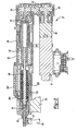
- a fastening system 21 of the present invention includes a fastener 23, a pair of sheet metal workpieces 25 and an installation machine 27.
- Machine 27 has a set of outer housings 29, a receiver assembly or nose piece 31, a C-frame 33 and a stationary die 35 mounted to the C-frame.
- An arm of an articulating robot 37 is preferably mounted to C-frame 33 but may be alternately mounted to housing 29.
- a computer controller 39 is connected to machine 27 and includes a programmable microprocessor, memory, an input device such as a keyboard or touch-screen, and an output device such as a display screen, CRT, display lights or the like.
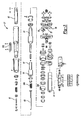
- An electric motor 51 has an internal armature which rotates when electromagnetically energized.
- the armature operably causes rotation of an output shaft, which in turn, rotates a set of two or three reduction, spur gears 55, 57 and 59.
- Spur gear 59 thereby rotates a nut housing 61 which is coupled to a rotatable ball or nut 65.
- Rotation of nut 65 causes an enmeshed spindle 67 to linearly advance and retract along a longitudinal axis.
- a punch holder 69 and an attached punch 81 linearly move with spindle 67.
- Parts 55, 57, 59, 61, 65, 67 and 69 act as a rotary-to-linear motion transmission thereby linearly advancing and retracting setting punch 81, a workpiece clamp 82 and an attached clamp ring 83.
- Controller 39 automatically recalls prestored characteristic data about the joint to be made at each predetermined location on workpiece 25, which may differ from the preceding or successor joints; for example, as to depth of fastener insertion, fastener type (e.g., length, material, shape, etc.), insertion speed, clamp force, workpiece thickness (e.g., use of a single sheet, use of two sheets, use of three sheets, nonuniform thickness of any combination thereof, etc.), or the like. Accordingly, the pre-stored, fastener characteristics defining the installation profile operation to be performed by the machine and the desired fastener to be selected are automatically retrieved from memory by the microprocessor.
- fastener type e.g., length, material, shape, etc.
- insertion speed e.g., clamp force
- workpiece thickness e.g., use of a single sheet, use of two sheets, use of three sheets, nonuniform thickness of any combination thereof, etc.
- a series of fasteners 23 are sequentially fed to a receiver area in nose piece 31 by pneumatic pressure through a feed hose 85 from a feeder assembly.
- One fastener 23 is aligned with punch 81 and one or more signals indicating presence of fastener 23 in its correct position and actual fastener length are sent by a sensor 301 to controller 39 in real-time for comparison to the pre-stored data.
- Sensor 301 is a linear encoder mounted within a sensor housing 303.
- electric motor 51 is automatically energized by controller 39 to allow a spring 305 to outwardly bias a clamp ring 83 against a punch-side surface of workpiece 25, and to also advance punch 81 which drives fastener 23.
- One or more signals indicating thickness of workpieces 25 are also sent by sensor 301 to controller 39 for a real-time comparison to the pre-stored data.
- a position sensor 307 is further provided within sensor housing 303 for sensing when punch 81 is in its fully retracted position.
- a load cell sensor 309 is mounted adjacent a proximal end of nut housing 61 to provide real-time information to controller 39 indicative of actual fastener setting force required for a comparison with the pre-stored data; this data indirectly verifies or allows variable control of depth of fastener insertion and the like.
- Sensors 301, 307 and 309 are connected to controller 39.
- controller 39 automatically determines if a satisfactory joint was created and sends the appropriate output signal indicating success, shuts down the process if unsatisfactory, changes punch speed or travel in real time if desired, and adds the record to historical quality control tracking data. Thereafter, the punch is retracted and machine is robotically moved to the next joint area or the workpiece is moved.
- Distal end 91 is caused to diverge outwardly by die 35 during installation, but fastener 23 is prevented from completely piercing through the die-side workpiece or from directly contacting the die, thereby creating a leakproof joint with distal end 91 encapsulated in die-side workpiece 25b.
- Fastener 23 preferably serves to secure together two (or more) workpiece panels 25a and 25b.
- the preferred nut embodiment of fastener 23 further includes an enlarged body 93 having internal, spiral threads 95 lining a bore, and a circular-cylindrical external surface 97.
- An outside, lateral surface 99 of distal end 91 is also circular-cylindrical, prior to installation, and of a smaller outer diameter than surface 97 of body 93.
- outside, lateral surface 99 of distal end 91 is of a hexagonal, octagonal or other polygonal shape, or has longitudinally extending grooves or ribs, so as to deter undesired rotation of the installed fastener 23 relative to workpiece 25 when a bolt is later attached.
- Figures 8 and 9 show the subsequent assembly step.
- a second alternate embodiment joint employs a fastener 23, as previously disclosed, attached to a single sheet metal, automotive vehicle, body panel or workpiece 25.
- An electrical connector component here a stamped metal eyelet 101 crimped onto an automotive grounding wire, is removably coupled to fastener 23 via an externally threaded shaft 105 of a bolt 107.
- Figure 9 illustrates a third alternate embodiment fastening system using an electronic circuit board component 109 secured to fastener 23 by an externally threaded bolt 107; fastener 23 is secured to a computer housing panel, bracket, workpiece 25 or other structure.
- Workpiece 25 can alternately represent an automotive vehicle body panel and component 109 can represent a polymeric or fibrous interior trim panel.
- Workpiece 25 is preferably a stamped aluminum or steel sheet but may alternately be a cast metal alloy or other materials suitable for a clinched fastener.
- Fastener 23 (and 223) is preferably carbon steel, heat treated to 30 and 55 Rc, but may alternately be aluminum or an aluminum alloy depending on the application requirements.
- a fourth alternate embodiment fastening system employs a stud fastener 223 which is clinched to a single (or alternately two or more) workpiece 225 in a self-piercing manner and with machinery as previously described with the preferred embodiment.
- This exemplary fastener 223 is a clinch stud having a longitudinally elongated shaft 293 with an external thread pattern 295 for later engagement by a component and nut.
- a distal clinching end 297 is encapsulated within and outwardly diverges into workpiece 225, without having to account for a loose slug being cut from the die-side workpiece.
Abstract
Description
- The present invention generally relates to fastening systems and more particularly pertains to a self-piercing, threaded fastener, joint and machine.
- It has recently become known to employ hydraulic and electric motor actuated machines to insert self-piercing rivets into sheet metal panels. For example, an electric motor-based device is disclosed in U.S. Patent No. 6,276,050 entitled "Riveting System and Process for Forming a Riveted Joint," which issued to Mauer et al. on August 21, 2001; this patent is incorporated by reference herein.
- A conventional clinch nut has also been employed for use with a single thickness, sheet metal, automotive panel. A slug is pierced from the panel by the nut and a ram of a setting machine thereafter removes the slug. Thus, an unobstructed hole is present from one side of the panel to the other through the nut. This is disadvantageous in that dirt, vehicle exhaust and other debris can move from one side of the panel to the other through the hole. Another conventional system provides a clinch stud used with a pre-drilled hole in a single sheet metal panel. A pneumatic setting machine is employed for both the traditional clinch nut and clinch stud systems. This has considerably different controllability and operational characteristics than an electric motor actuator. Furthermore, other traditional clinch nuts and clinch studs employ a pre-pierced panel opening, prior to insertion of the nut or stud, which adds an expensive extra manufacturing step and complexity to the setting tool, as well as adds undesirable additional tolerance variations which may lead to the creation of vehicle noise and vibration at the joint.
- In accordance with the present invention, the preferred embodiment of a fastening system includes a self-piercing fastener having a thread-like pattern. In another aspect of the present invention, a fastener insertion machine employs an electromagnetic actuator without fluid actuation. A further aspect of the present invention uses a rotary-to-linear transmission within the insertion machine to advance the fastener. Yet another aspect of the present invention provides a clinch fastener for joining multiple workpieces. Additionally, another aspect of the present invention provides a leakproof joint between the fastener and the workpiece. A leading end of a threaded fastener is encapsulated within a panel in a further aspect of the present invention. In still another aspect of the present invention, a self-piercing fastener is a clinch nut or a clinch stud. A method of attaching a fastener to at least one workpiece is also provided.
- The fastening system of the present invention is advantageous over conventional devices in that a joint between a workpiece and a fastener is created which prevents the passage of dirt, debris and exhaust through the joint area. Another advantage of the present invention is the real-time controllability, changes, and accuracy of the insertion machine used to set the fastener, realized through use of the electromagnetic actuator, a real-time sensing system and control logic. This improves automatic fastening characteristic recognition, quality, flexibility and result tracking. Machine and processing costs and complexity are additionally reduced through the self-piercing nature of the fastener and process. Moreover, the fastening system of the present invention is advantageously suitable for use in creating a two-way joint; the clinching section of the fastener joins two or more sheet metal panels while the body of the fastener also secures a component such as an electrical connector, trim panel and/or a circuit board. Additional features and benefits will be further disclosed hereinafter with reference to the appended claims and accompanying drawings
- Figure 1 is a perspective view showing an installation machine and joint employed in the preferred embodiment of the fastening system of the present invention;
- Figure 2 is a longitudinal cross-sectional view, taken along line 2-2 of Figure 1, showing the preferred embodiment installation machine;
- Figure 3 is an exploded perspective view showing the preferred embodiment installation machine;
- Figure 4 is an exploded perspective view showing a sensor assembly employed in the preferred embodiment installation machine;
- Figure 5A is an end elevational view showing a nut fastener employed in a preferred embodiment of the fastening system of the present invention, as viewed prior to installation;
- Figure 5B is an end elevational view showing a nut fastener employed in a first alternate embodiment of the fastening system of the present invention, as viewed prior to installation;
- Figure 6 is a cross-sectional view, taken along line 6-6 of Figure 5A, showing the preferred embodiment of the nut fastener, as viewed prior to installation;
- Figure 7 is a cross-sectional view, similar to that of Figure 6, showing the joint of the preferred embodiment fastening system, as viewed after installation;
- Figure 8 is a cross-sectional view, similar to that of Figure 7, showing a second alternate embodiment fastening system of the present invention;
- Figure 9 is a cross-sectional view, similar to that of Figure 7, showing a third alternate embodiment fastening system of the present invention; and
- Figure 10 is a cross-sectional view, similar to that of Figure 7, showing a fourth alternate embodiment fastening system of the present invention.
-
- Referring to Figures 1-3, the preferred embodiment of a
fastening system 21 of the present invention includes afastener 23, a pair ofsheet metal workpieces 25 and aninstallation machine 27.Machine 27 has a set ofouter housings 29, a receiver assembly ornose piece 31, a C-frame 33 and astationary die 35 mounted to the C-frame. An arm of an articulatingrobot 37 is preferably mounted to C-frame 33 but may be alternately mounted tohousing 29. Acomputer controller 39 is connected tomachine 27 and includes a programmable microprocessor, memory, an input device such as a keyboard or touch-screen, and an output device such as a display screen, CRT, display lights or the like. - An
electric motor 51 has an internal armature which rotates when electromagnetically energized. The armature operably causes rotation of an output shaft, which in turn, rotates a set of two or three reduction,spur gears Spur gear 59 thereby rotates anut housing 61 which is coupled to a rotatable ball ornut 65. Rotation ofnut 65 causes an enmeshedspindle 67 to linearly advance and retract along a longitudinal axis. Apunch holder 69 and an attachedpunch 81 linearly move withspindle 67.Parts setting punch 81, aworkpiece clamp 82 and an attachedclamp ring 83. -
Controller 39 automatically recalls prestored characteristic data about the joint to be made at each predetermined location onworkpiece 25, which may differ from the preceding or successor joints; for example, as to depth of fastener insertion, fastener type (e.g., length, material, shape, etc.), insertion speed, clamp force, workpiece thickness (e.g., use of a single sheet, use of two sheets, use of three sheets, nonuniform thickness of any combination thereof, etc.), or the like. Accordingly, the pre-stored, fastener characteristics defining the installation profile operation to be performed by the machine and the desired fastener to be selected are automatically retrieved from memory by the microprocessor. A series offasteners 23 are sequentially fed to a receiver area innose piece 31 by pneumatic pressure through afeed hose 85 from a feeder assembly. Onefastener 23 is aligned withpunch 81 and one or more signals indicating presence offastener 23 in its correct position and actual fastener length are sent by asensor 301 to controller 39 in real-time for comparison to the pre-stored data.Sensor 301 is a linear encoder mounted within asensor housing 303. Thereafter,electric motor 51 is automatically energized bycontroller 39 to allow aspring 305 to outwardly bias aclamp ring 83 against a punch-side surface ofworkpiece 25, and to also advancepunch 81 which drivesfastener 23. One or more signals indicating thickness ofworkpieces 25 are also sent bysensor 301 to controller 39 for a real-time comparison to the pre-stored data. A position sensor 307 is further provided withinsensor housing 303 for sensing whenpunch 81 is in its fully retracted position. Furthermore, aload cell sensor 309 is mounted adjacent a proximal end ofnut housing 61 to provide real-time information to controller 39 indicative of actual fastener setting force required for a comparison with the pre-stored data; this data indirectly verifies or allows variable control of depth of fastener insertion and the like.Sensors controller 39. - The actual transmission force, motor current, motor amperage draw or the like is automatically sensed by the sensors during fastener installation wherein
controller 39 automatically determines if a satisfactory joint was created and sends the appropriate output signal indicating success, shuts down the process if unsatisfactory, changes punch speed or travel in real time if desired, and adds the record to historical quality control tracking data. Thereafter, the punch is retracted and machine is robotically moved to the next joint area or the workpiece is moved. - Referring now to Figures 1, 2, 5A, 6 and 7, a tapered, circular-cylindrical,
distal end 91 offastener 23, preferably a clinch nut, self-pierces and cuts its own hole completely through the punch-side workpiece 25a and only partially through the die-side workpiece 25b.Distal end 91 is caused to diverge outwardly by die 35 during installation, butfastener 23 is prevented from completely piercing through the die-side workpiece or from directly contacting the die, thereby creating a leakproof joint withdistal end 91 encapsulated in die-side workpiece 25b.Fastener 23 preferably serves to secure together two (or more)workpiece panels fastener 23 further includes an enlargedbody 93 having internal,spiral threads 95 lining a bore, and a circular-cylindricalexternal surface 97. An outside,lateral surface 99 ofdistal end 91 is also circular-cylindrical, prior to installation, and of a smaller outer diameter thansurface 97 ofbody 93. In the first alternate embodiment illustrated in Figure 5B, outside,lateral surface 99 ofdistal end 91 is of a hexagonal, octagonal or other polygonal shape, or has longitudinally extending grooves or ribs, so as to deter undesired rotation of the installedfastener 23 relative toworkpiece 25 when a bolt is later attached. - Figures 8 and 9 show the subsequent assembly step. In Figure 8, a second alternate embodiment joint employs a
fastener 23, as previously disclosed, attached to a single sheet metal, automotive vehicle, body panel orworkpiece 25. An electrical connector component, here a stampedmetal eyelet 101 crimped onto an automotive grounding wire, is removably coupled tofastener 23 via an externally threadedshaft 105 of abolt 107. Figure 9 illustrates a third alternate embodiment fastening system using an electroniccircuit board component 109 secured tofastener 23 by an externally threadedbolt 107;fastener 23 is secured to a computer housing panel, bracket,workpiece 25 or other structure.Workpiece 25 can alternately represent an automotive vehicle body panel andcomponent 109 can represent a polymeric or fibrous interior trim panel.Workpiece 25 is preferably a stamped aluminum or steel sheet but may alternately be a cast metal alloy or other materials suitable for a clinched fastener. Fastener 23 (and 223) is preferably carbon steel, heat treated to 30 and 55 Rc, but may alternately be aluminum or an aluminum alloy depending on the application requirements. - As can be observed in Figure 10, a fourth alternate embodiment fastening system employs a
stud fastener 223 which is clinched to a single (or alternately two or more) workpiece 225 in a self-piercing manner and with machinery as previously described with the preferred embodiment. Thisexemplary fastener 223 is a clinch stud having a longitudinallyelongated shaft 293 with anexternal thread pattern 295 for later engagement by a component and nut. Adistal clinching end 297 is encapsulated within and outwardly diverges intoworkpiece 225, without having to account for a loose slug being cut from the die-side workpiece. - While multiple embodiments of the present invention have been disclosed, it should be appreciated that various changes may be made which still fall within the scope of the present invention. For example, alternate engagement patterns may be employed on the fastener other than threads. It is also envisioned that the quantity and positioning of gears and shafts of the transmission can differ depending on the force reduction or increase, speed, travel, and packaging requirements desired for a specific use. Furthermore, the machine of the present invention may be stationarily mounted to a factory floor rather than movably attached to a robot. A fluid powered fastener setting machine can alternately be employed to create the disclosed joints, however, many operational and quality benefits will not be achieved without use of the preferred electric motor-actuated, rotary-to-linear driven machine disclosed. While various materials have been disclosed, it should be appreciated that a variety of other materials can be employed. It is intended by the following claims to cover these and any other departures from the disclosed embodiments which fall within the true spirit of this invention.
Claims (48)
- A fastening system comprising:at least one workpiece having a first outside surface and a second outside surface substantially opposite the first outside surface; anda fastener comprising:(a) a distal end operably self-piercing the first outside surface and not the second outside surface;(b) the distal end having a diverging shape when fully attached to the workpiece; and(c) a body including a thread-like pattern.
- The fastening system of Claim 1 further comprising a machine operable to automatically insert the fastener into the workpiece, the machine comprising an electromagnetic and non-fluid powered actuator.
- The fastening system of Claim 2 further comprising a sensor operably sensing a fastener characteristic and a controller automatically varying a fastener insertion feature of the machine in response to the fastener characteristic sensed.
- The fastening system of Claim 3 wherein the fastener characteristic is fastener size.
- The fastening system of Claim 3 wherein the fastener characteristic is fastener insertion force.
- The fastening system of Claim 3 wherein the fastener characteristic is fastener presence in the machine.
- The fastening system of Claim 3 wherein the fastener characteristic is fastener location relative to the workpiece.
- The fastening system of Claim 3 wherein the fastener characteristic is thickness of the workpiece.
- The fastening system of Claim 3 wherein the fastener insertion feature is insertion speed, greater than zero.
- The fastening system of Claim 3 wherein the fastener insertion feature is de-energization of the actuator.
- The fastening system of Claim 2 wherein the machine further comprises a punch and a transmission, the transmission operably converting rotary motion of the actuator to linear motion of the punch.
- The fastening system of anyone of the preceding Claims wherein the at least one workpiece includes two sheet metal workpieces, with the first surface being a punch-side exterior surface of one of the workpieces and the second surface being a die-side surface of the other of the workpieces.
- The fastening system of Claim 12 wherein the fastener self-pierces through the punch-side one of the workpieces, the fastener self-pierces partially in a die-side one of the workpieces, and the fastener does not project completely through the die-side one of the workpieces.
- The fastening system of anyone of the preceding Claims wherein the fastener is a self-piercing nut comprising a piercing end and including a bore internally located in the body, and the thread is located in the bore
- The fastening system of Claim 12 further comprising a bolt enmeshed with the bore of the fastener.
- The fastening system of Claim 12 wherein the nut comprises an enlarged body having a substantially circular-cylindrical, lateral outside surface.
- The fastening system of Claim 12, wherein the nut has a diverging end located in at least one of the workpieces.
- The fastening system of anyone of the preceding Claims I to 13 wherein the body of the fastener is a substantially cylindrical and elongated stud.
- The fastening system of Claim 18 comprising at least one workpiece and a clinch stud secured to the workpiece, an elongated shaft of the stud having an external pattern exposed from the workpiece, a diverging and self-piercing end of the stud being entirely encapsulated within the workpiece.
- The fastening system of anyone of the preceding Claims wherein the at least one workpiece includes at least two metallic panels.
- The fastening system of Claim 18 wherein the external pattern is a spiral thread, and an end section of the stud adjacent the self-piercing end has a substantially cylindrical outside surface and a hollow cavity prior to installation.
- A fastening system according to anyone of the preceding Claims comprising:wherein the transmission operably transmits rotary motion of the motor to linear motion of the punch to operably push the fastener.a threaded fastener; anda machine automatically operable to drive the fastener, the machine comprising:(a) a C-frame;(b) at least one transmission housing coupled to the C-frame;(c) an electric motor;(d) a transmission coupled to the motor, at least a portion of the transmission being located in the transmission housing; and(e) a punch coupled to the transmission;
- The fastening system of Claim 22 further comprising a threaded member removably enmeshed with the fastener and a component secured to the fastener by the member.
- The fastening system of Claim 22 wherein the component is an electrical connector.
- The fastening system of Claim 22 wherein the component is a circuit board.
- The fastening system of Claim 22 further comprising:a die attached to the C-frame, the die being substantially aligned with the punch, the fastener being prevented from directly contacting the die; anda robotic arm coupled to at least one of the housing and the C-frame.
- The fastening system of Claim 22 further comprising:a robotic arm coupled to at least one of the housing and the C-frame.
- A fastener for the fastening system of one of the preceding Claims comprising:an elongated shaft including an external thread-like pattern with an outside diameter; anda workpiece-engaging section attached to the shaft at a proximal end and having a self-piercing distal end;the workpiece-engaging section having a pre-installed outside diameter substantially the same as that of the shaft.
- The fastener of Claim 28 wherein the distal end outwardly diverges when installed.
- The fastener of one of Claims 28 and 29 wherein the workpiece-engaging section directly extends from the shaft free of a transversely enlarged flange.
- The fastener of one of Claims 28 to 30 wherein the workpiece-engaging section is substantially hollow within a pre-installed substantially cylindrical wall, a roof of the workpiece-engaging section adjacent the shaft is substantially flat and parallel to an exposed end of the shaft.
- A method of attaching a threaded fastener to a panel using a punch and a die, the method comprising:(a) advancing the punch;(b) piercing the panel with the threaded fastener; and(c) preventing the threaded fastener from directly contacting against the die.
- The method of Claim 32 further comprising piercing the fastener completely through the panel and only partially piercing the fastener through a second panel.
- The method of one of Claims 32 and 33 further comprising converting rotary motion of an electric motor to linear motion of the punch in order to linearly advance the threaded fastener.
- The method of one of Claims 32 to 34 further comprising robotically moving the punch and die to a position adjacent the panel.
- The method of one of Claims 32 to 35 further comprising attaching an electrical component to the threaded fastener.
- The method of one of Claims 32 to 35 further comprising attaching a circuit board to the threaded fastener.
- The method of one of Claims 32 to 37 wherein the fastener is a self-piercing nut, further comprising outwardly diverging an end of the fastener during installation, completely encapsulating the end of the fastener within the panel and creating a leakproof joint between the fastener and the panel.
- The method of one of Claims 32 to 38 comprising:(a) creating a joint between a threaded fastener, and at least one workpiece using an installation machine(b) rotating an electromagnetic member of the machine to create rotary motion;(c) converting the rotary motion to linear motion for a second member of the machine;(d) linearly advancing the threaded fastener toward the at least one workpiece; and(e) self-piercing the at least one workpiece with the threaded fastener.
- The method of Claim 39 further comprising at least one sensor coupled to the machine and a controller connected to the machine, the sensor operably sensing a fastener characteristic and the controller automatically varying a fastener insertion feature of the machine in response to the fastener characteristic sensed.
- The method of Claim 40 wherein the fastener characteristic is fastener insertion force.
- The method of Claim 40 wherein he fastener insertion feature is insertion speed, greater than zero.
- The method of Claim 39 further comprising attaching an electrical component to the threaded fastener.
- The method of Claim 39 further comprising attaching a circuit board to the threaded fastener.
- The method of one of Claims 39 to 44 wherein the fastener is a self-piercing nut, further comprising outwardly diverging an end of the fastener during installation, completely encapsulating the end of the fastener within the panel and creating a leakproof joint between the fastener and the panel.
- The method of one of Claims 39 to 45 further comprising preventing the threaded fastener from completely penetrating through a die-side surface of the at least one workpiece.
- The method of one of Claims 39 to 46 further comprising removably engaging a second threaded member with a threaded portion of the threaded fastener to secure a component to the workpiece.
- The method of one of Claims 39 to 47 further comprising fastening together at least two of the workpieces with a self-piercing segment of the threaded fastener.
Applications Claiming Priority (4)
| Application Number | Priority Date | Filing Date | Title |
|---|---|---|---|
| US52436003P | 2003-11-21 | 2003-11-21 | |
| US524360P | 2003-11-21 | ||
| US735305 | 2003-12-11 | ||
| US10/735,305 US7032296B2 (en) | 2003-11-21 | 2003-12-11 | Self-piercing fastening system |
Publications (2)
| Publication Number | Publication Date |
|---|---|
| EP1533054A2 true EP1533054A2 (en) | 2005-05-25 |
| EP1533054A3 EP1533054A3 (en) | 2005-06-15 |
Family
ID=34437382
Family Applications (1)
| Application Number | Title | Priority Date | Filing Date |
|---|---|---|---|
| EP04002434A Withdrawn EP1533054A3 (en) | 2003-11-21 | 2004-02-04 | Self-piercing fastening system |
Country Status (3)
| Country | Link |
|---|---|
| US (1) | US7032296B2 (en) |
| EP (1) | EP1533054A3 (en) |
| JP (1) | JP2005153008A (en) |
Cited By (9)
| Publication number | Priority date | Publication date | Assignee | Title |
|---|---|---|---|---|
| WO2010141020A1 (en) * | 2009-06-04 | 2010-12-09 | Fastener Advance Products | Improved pierce nut installation tool |
| EP2359014A1 (en) * | 2008-11-21 | 2011-08-24 | Pem Management, Inc. | Piercing standoff |
| CN102784874A (en) * | 2012-08-16 | 2012-11-21 | 西北工业大学 | Hand-held electromagnetic riveting gun buffering and guiding mechanism |
| US20150047171A1 (en) * | 2013-08-14 | 2015-02-19 | Whitesell International Corporation | Method of attaching a nut to a panel |
| EP3117923A1 (en) * | 2015-07-17 | 2017-01-18 | Robert Bosch Gmbh | Method for connecting at least two components by means of a self-piercing rivet device and manufacturing equipment |
| EP3117924A1 (en) * | 2015-07-17 | 2017-01-18 | Robert Bosch Gmbh | Method for connecting at least two components by means of a self-piercing rivet device and manufacturing equipment |
| DE102015014941A1 (en) | 2015-11-18 | 2017-05-18 | Audi Ag | Method for producing a connection between a functional element and a plate-shaped component and device for carrying out the method |
| CN106825362A (en) * | 2015-10-13 | 2017-06-13 | 罗伯特·博世有限公司 | Method for connecting at least two components by stamping riveting device |
| CN108723279A (en) * | 2018-05-22 | 2018-11-02 | 镇江成功汽车零部件有限公司 | Aluminium vehicle body Double-screw bolt riveting apparatus |
Families Citing this family (29)
| Publication number | Priority date | Publication date | Assignee | Title |
|---|---|---|---|---|
| US9015920B2 (en) * | 1997-07-21 | 2015-04-28 | Newfrey Llc | Riveting system and process for forming a riveted joint |
| US6276050B1 (en) * | 1998-07-20 | 2001-08-21 | Emhart Inc. | Riveting system and process for forming a riveted joint |
| GB0111265D0 (en) * | 2001-05-05 | 2001-06-27 | Henrob Ltd | Fastener insertion apparatus and method |
| CA2517185A1 (en) * | 2003-03-19 | 2004-11-04 | Fabristeel Products, Inc. | Self-diagnosing pierce nut installation apparatus |
| US7313852B2 (en) * | 2003-12-23 | 2008-01-01 | Magna Structural Systems, Inc. | Method of forming a rivet using a riveting apparatus |
| ATE528087T1 (en) * | 2004-03-24 | 2011-10-15 | Newfrey Llc | RIVET SYSTEM FOR FORMING A RIVET CONNECTION |
| DE102005026219B4 (en) * | 2005-06-07 | 2007-12-13 | Poly-Clip System Gmbh & Co. Kg | Clip machine and method for setting up a clip machine |
| TWI298120B (en) * | 2005-12-05 | 2008-06-21 | Quanta Comp Inc | Mobile electronic device housing structure |
| DE102006049998A1 (en) * | 2006-10-24 | 2008-04-30 | Zf Friedrichshafen Ag | Arrangement of pin in bore of disc, particularly planetary gear pin in guiding disc of planet carrier, has groove at extreme end of pin, which is secured against turning by caulking with material of disc in groove |
| US8549723B2 (en) * | 2007-05-11 | 2013-10-08 | The Boeing Company | Method and apparatus for squeezing parts such as fasteners |
| US7997190B2 (en) * | 2007-09-14 | 2011-08-16 | Pem Management, Inc. | Dual force ram drive for a screw press |
| US8434215B2 (en) * | 2008-08-05 | 2013-05-07 | Newfrey Llc | Self-piercing rivet setting machine |
| US20110083316A1 (en) * | 2009-10-12 | 2011-04-14 | Alan Nobis | Riveting device for metal sheets |
| US8881364B2 (en) | 2010-12-03 | 2014-11-11 | Btm Corporation | Pierce nut insertion tool |
| DE102012003819A1 (en) * | 2012-02-27 | 2013-08-29 | Profil Verbindungstechnik Gmbh & Co. Kg | Functional element for fluid-tight attachment to a sheet metal part, assembly part and method |
| KR101759533B1 (en) * | 2012-07-13 | 2017-07-19 | 헨롭 리미티드 | Blind riveting apparatus and methods |
| US9027220B2 (en) * | 2012-08-07 | 2015-05-12 | Newfrey Llc | Rivet setting machine |
| US9366279B2 (en) * | 2013-03-13 | 2016-06-14 | Ford Global Technologies, Llc | Rivets with anti-rotational features |
| KR101834320B1 (en) | 2014-01-16 | 2018-03-05 | 헨롭 리미티드 | Linear actuator assembly |
| DE102015102806A1 (en) * | 2015-02-27 | 2016-09-01 | Gustav Klauke Gmbh | Method for operating a hydraulically operated hand-held device and hydraulically operated hand-held device |
| US10415622B2 (en) * | 2016-05-03 | 2019-09-17 | General Electric Company | Method and system for hybrid gang channel bolted joint |
| DE102016111874A1 (en) | 2016-06-29 | 2018-01-04 | Gustav Klauke Gmbh | Method for operating a hydraulically operated hand-held device and hydraulically operated hand-held device |
| DE102016119479A1 (en) * | 2016-10-12 | 2018-04-12 | Profil Verbindungstechnik Gmbh & Co. Kg | Functional element for fluid-tight attachment to a sheet metal part, assembly part and method |
| US10500632B2 (en) * | 2016-11-08 | 2019-12-10 | Penn Automotive, Inc. | Self-piercing rivet installation apparatus |
| GB2563441B (en) * | 2017-06-16 | 2022-03-23 | Atlas Copco Ias Uk Ltd | Die changing apparatus |
| US11673243B2 (en) | 2018-09-05 | 2023-06-13 | Milwaukee Electric Tool Corporation | Blind rivet nut-setting tool |
| EP3626982B1 (en) * | 2018-09-21 | 2022-02-16 | Newfrey LLC | Self-piercing rivet |
| JP6824352B1 (en) * | 2019-09-19 | 2021-02-03 | プレス工業株式会社 | Locknut |
| EP4094864A4 (en) * | 2020-01-17 | 2023-11-15 | Dai-ichi Dentsu Ltd. | Press device |
Citations (2)
| Publication number | Priority date | Publication date | Assignee | Title |
|---|---|---|---|---|
| DE19922864A1 (en) * | 1999-05-19 | 2000-12-07 | Rudolf Mueller | Method and device for attaching an auxiliary joining part to a sheet-like workpiece and workpiece with an auxiliary joining part |
| US6276050B1 (en) * | 1998-07-20 | 2001-08-21 | Emhart Inc. | Riveting system and process for forming a riveted joint |
Family Cites Families (79)
| Publication number | Priority date | Publication date | Assignee | Title |
|---|---|---|---|---|
| US491182A (en) * | 1893-02-07 | Thill-couplin | ||
| US1500021A (en) * | 1922-02-13 | 1924-07-01 | Wilson Walter Gordon | Rivet or clip |
| US3281171A (en) * | 1963-12-03 | 1966-10-25 | United Carr Inc | Self-piercing pronged t nut |
| US3969809A (en) * | 1974-03-25 | 1976-07-20 | Multifastener Corporation | Self-fastening nut, panel assembly and apparatus |
| US3961408A (en) * | 1975-05-05 | 1976-06-08 | Multifastener Corporation | Fastener installation head |
| US3971116A (en) * | 1975-05-05 | 1976-07-27 | Multifastener Corporation | Fastener installation head |
| US3969808A (en) * | 1975-05-05 | 1976-07-20 | Multifastener Corporation | Fastener installation head |
| US3946478A (en) * | 1975-05-05 | 1976-03-30 | Multifastener Corporation | Fastener installation head |
| US3942235A (en) * | 1975-05-05 | 1976-03-09 | Multifastener Corporation | Fastener installation head |
| US4124050A (en) * | 1976-09-03 | 1978-11-07 | Action Machining Corp. | Action piercing fastener |
| FR2433126A1 (en) * | 1978-08-07 | 1980-03-07 | Multifastener Corp | Self-clinching nut - has V=shaped groove which deforms metal around hole into which nut is inserted |
| US4242793A (en) * | 1979-05-25 | 1981-01-06 | Multifastener Corporation | Nut guide for installation head |
| US5237733A (en) * | 1980-02-02 | 1993-08-24 | Multifastener Corporation | Female die assembly for attaching a self-attaching fastening element and method of attachment |
| US4893394A (en) * | 1980-02-02 | 1990-01-16 | Multifastener Corporation | Installation apparatus for attaching a female element to a panel |
| US4700470A (en) * | 1980-02-02 | 1987-10-20 | Multifastener Corporation | Fastener installation apparatus |
| US5564873A (en) * | 1980-02-02 | 1996-10-15 | Multifastener Corporation | Self-attaching fastening element and method of attachment |
| US4713872A (en) * | 1980-02-02 | 1987-12-22 | Multifastener Corporation | Method of attaching fastening element to a panel |
| US5146672A (en) * | 1980-02-02 | 1992-09-15 | Multifastener Corporation | Die assembly for attaching a female element |
| US5207588A (en) * | 1980-02-02 | 1993-05-04 | Multifastener Corporation | Electrical grounding stud |
| US4911592A (en) * | 1980-02-02 | 1990-03-27 | Multifastener Corporation | Method of installation and installation apparatus |
| US4765057A (en) * | 1980-02-02 | 1988-08-23 | Multifastener Corporation | Self-attaching fastener, panel assembly and installation apparatus |
| US4831698A (en) * | 1983-03-28 | 1989-05-23 | Multifastener Corporation | Method of attaching a female element to a panel |
| DE3003908C2 (en) * | 1980-02-02 | 1984-10-18 | Profil-Verbindungstechnik Gmbh & Co Kg, 6382 Friedrichsdorf | Stud bolts with punching and riveting behavior |
| US4802803A (en) * | 1980-02-02 | 1989-02-07 | Multifastener Corporation | Fastening element and panel assembly |
| US4610072A (en) * | 1983-12-21 | 1986-09-09 | Multifastener Corporation | Method of installing a fastener to a panel |
| US5067224A (en) * | 1980-02-02 | 1991-11-26 | Multifastener Corporation | Method of installing self-attaching fastener and apparatus |
| US4810143A (en) * | 1983-12-21 | 1989-03-07 | Multifastener Corporation | Fastener and panel assembly |
| US5560094A (en) * | 1980-02-02 | 1996-10-01 | Multifastener Corporation | Method of attaching a fastener to a panel |
| US5072518A (en) * | 1980-02-02 | 1991-12-17 | Multifastener Corporation | Installation head for attaching female fasteners |
| US5617652A (en) * | 1980-02-02 | 1997-04-08 | Multifastener Corporation | Fastener installation and method |
| US4633560A (en) * | 1980-02-02 | 1987-01-06 | Multifastener Corporation | Self-attaching fastener, die set |
| US4555838A (en) * | 1983-03-28 | 1985-12-03 | Multifastener Corp. | Method of installing self-attaching fasteners |
| ZA81334B (en) | 1980-02-04 | 1982-08-25 | Illinois Tool Works | Clinch nut and assembly machine |
| US4348796A (en) * | 1980-02-06 | 1982-09-14 | Multifastener Corporation | Nut installation apparatus and method |
| US4442584A (en) * | 1980-02-06 | 1984-04-17 | Multifastener Corporation | Nut installation apparatus, method and controls |
| US4679690A (en) * | 1980-05-20 | 1987-07-14 | Multifastener Corporation | Fastener orienting, tapping and collection system |
| US4532664A (en) * | 1980-05-20 | 1985-08-06 | Multifastener Corporation | Fastener orienting, tapping and collection system |
| US4338694A (en) * | 1980-05-20 | 1982-07-13 | Multifastener Corporation | Fastener orienting, tapping and collection system |
| US4476599A (en) * | 1980-05-20 | 1984-10-16 | Multifastener Corporation | Fastener orienting, tapping and collection system |
| US5441417A (en) * | 1981-01-28 | 1995-08-15 | Multifastener Corporation | Electrical grounding stud |
| US5722139A (en) * | 1981-01-28 | 1998-03-03 | Multifastener Corporation | Installation apparatus for attaching a fastener to a panel |
| US5174018A (en) * | 1981-01-28 | 1992-12-29 | Multifastener Corporation | Die button with staking features |
| USRE35619E (en) * | 1981-01-28 | 1997-10-07 | Multifastener Corporation | Installation apparatus for installing self-attaching fasteners |
| JPS58109710A (en) * | 1981-12-24 | 1983-06-30 | 有限会社新城製作所 | Piercing nut |
| US4574453A (en) * | 1982-04-30 | 1986-03-11 | Btm Corporation | Self-attaching fastener and method of securing same to sheet material |
| US4484385A (en) * | 1982-07-13 | 1984-11-27 | Multifastener Corporation | Method of forming sealed nut and panel assembly |
| US4630363A (en) * | 1982-07-13 | 1986-12-23 | Multifastener Corporation | Sealed nut and panel assembly apparatus |
| US4505416A (en) * | 1982-07-13 | 1985-03-19 | Multifastener Corporation | Fastener installation apparatus |
| US4729163A (en) * | 1983-12-21 | 1988-03-08 | Multifastener Corporation | Die set assembly for attaching a fastener |
| DE3404118A1 (en) * | 1984-02-07 | 1985-08-14 | Profil-Verbindungstechnik Gmbh & Co Kg, 6382 Friedrichsdorf | METHOD AND DEVICE FOR ATTACHING A NUT TO A PLATE-SHAPED WORKPIECE |
| US5531552A (en) | 1984-08-03 | 1996-07-02 | Multifastener Corporation | Self-attaching nut and method of making same |
| US4653970A (en) * | 1985-08-22 | 1987-03-31 | Multifastener Corporation | Quarter-turn fastener |
| DE3610675C2 (en) * | 1986-03-29 | 1994-12-15 | Profil Verbindungstechnik Gmbh | Method and device for attaching a hollow body to a tabular workpiece |
| US4649753A (en) * | 1986-04-08 | 1987-03-17 | Multifastener Corporation | Verification probe |
| US4825527A (en) * | 1988-01-25 | 1989-05-02 | Multifastener Corporation | Method of attaching an element to a panel |
| US5140735A (en) * | 1990-01-16 | 1992-08-25 | Multifastener Corporation | Die member for attaching a self-piercing and riveting fastener |
| US5056207A (en) * | 1990-01-16 | 1991-10-15 | Multifastener Corporation | Method of attaching a self-piercing and riveting fastener and improved die member |
| US5020950A (en) * | 1990-03-06 | 1991-06-04 | Multifastener Corporation | Riveting fastener with improved torque resistance |
| US5239740A (en) * | 1991-05-01 | 1993-08-31 | Multifastener Corporation | Method of installing sealing fastener |
| US5208963A (en) * | 1991-05-01 | 1993-05-11 | Multifastener Corporation | Die for installing sealing fastener |
| EP0553822B1 (en) * | 1992-01-31 | 1996-11-27 | Multifastener Corporation | Self-attaching fastener and installation die |
| US5549430A (en) | 1992-01-31 | 1996-08-27 | Multifastener Corporation | Self-attaching fastener and installation die |
| DE59406808D1 (en) * | 1993-07-01 | 1998-10-08 | Braendle Ag Metallbau | Method and device for cleaning surfaces |
| US5445483A (en) * | 1993-08-23 | 1995-08-29 | Emhart Inc. | Female clinch fastener with cold-formed locking flange and associated installation method |
| US5487215A (en) * | 1994-02-18 | 1996-01-30 | Multifastener Corporation | Self-adjusting head |
| JP2543327B2 (en) * | 1994-04-22 | 1996-10-16 | 憲士 中山 | Retaining wall structure and retaining wall construction method |
| US5501552A (en) * | 1994-04-29 | 1996-03-26 | Goldco Industries, Inc. | Conveying system for unstable articles having a neck ring |
| AU1182497A (en) * | 1995-12-20 | 1997-07-14 | Ariel Industries Plc | Self-pierce rivet |
| US6226854B1 (en) * | 1998-04-30 | 2001-05-08 | Fabristeel Products, Inc. | Fastener die member |
| DE19909821A1 (en) | 1999-03-05 | 2000-09-07 | Boellhoff Gmbh | Rivet for joining sheet metal is die-cast from metal powder, e.g. high-grade steel, titanium or aluminum. |
| US20020172573A1 (en) * | 1999-03-24 | 2002-11-21 | Pamer W. Richard | Self-piercing clinch nut |
| US6220804B1 (en) * | 1999-03-24 | 2001-04-24 | R B & W Corporation | Self-piercing clinch nut |
| US6325584B1 (en) * | 1999-03-30 | 2001-12-04 | Richard Bergner Gmbh | Self-piercing rivet |
| US6789309B2 (en) * | 2000-02-22 | 2004-09-14 | Newfrey Llc | Self-piercing robotic rivet setting system |
| EP1366304A2 (en) | 2001-03-09 | 2003-12-03 | Newfrey LLC | Self-punching rivet, method and device for setting a rivet element and the use thereof |
| GB0111265D0 (en) * | 2001-05-05 | 2001-06-27 | Henrob Ltd | Fastener insertion apparatus and method |
| US20030101566A1 (en) * | 2001-12-05 | 2003-06-05 | Ladouceur Harold A. | Self-piercing element, method of attachment and die member |
| US6732420B2 (en) * | 2002-03-08 | 2004-05-11 | General Motors Corporation | Method for riveting metal members therewith |
| US6802682B2 (en) * | 2002-11-18 | 2004-10-12 | General Motors Corporation | Spiraled self-piercing rivet |
-
2003
- 2003-12-11 US US10/735,305 patent/US7032296B2/en not_active Expired - Lifetime
-
2004
- 2004-01-23 JP JP2004015693A patent/JP2005153008A/en active Pending
- 2004-02-04 EP EP04002434A patent/EP1533054A3/en not_active Withdrawn
Patent Citations (2)
| Publication number | Priority date | Publication date | Assignee | Title |
|---|---|---|---|---|
| US6276050B1 (en) * | 1998-07-20 | 2001-08-21 | Emhart Inc. | Riveting system and process for forming a riveted joint |
| DE19922864A1 (en) * | 1999-05-19 | 2000-12-07 | Rudolf Mueller | Method and device for attaching an auxiliary joining part to a sheet-like workpiece and workpiece with an auxiliary joining part |
Cited By (13)
| Publication number | Priority date | Publication date | Assignee | Title |
|---|---|---|---|---|
| EP2359014A1 (en) * | 2008-11-21 | 2011-08-24 | Pem Management, Inc. | Piercing standoff |
| EP2359014A4 (en) * | 2008-11-21 | 2013-05-08 | Pem Man Inc | Piercing standoff |
| WO2010141020A1 (en) * | 2009-06-04 | 2010-12-09 | Fastener Advance Products | Improved pierce nut installation tool |
| CN102784874A (en) * | 2012-08-16 | 2012-11-21 | 西北工业大学 | Hand-held electromagnetic riveting gun buffering and guiding mechanism |
| CN102784874B (en) * | 2012-08-16 | 2014-07-16 | 西北工业大学 | Hand-held electromagnetic riveting gun buffering and guiding mechanism |
| US9347481B2 (en) * | 2013-08-14 | 2016-05-24 | Whitesell International Corporation | Method of attaching a nut to a panel |
| US20150047171A1 (en) * | 2013-08-14 | 2015-02-19 | Whitesell International Corporation | Method of attaching a nut to a panel |
| EP3117923A1 (en) * | 2015-07-17 | 2017-01-18 | Robert Bosch Gmbh | Method for connecting at least two components by means of a self-piercing rivet device and manufacturing equipment |
| EP3117924A1 (en) * | 2015-07-17 | 2017-01-18 | Robert Bosch Gmbh | Method for connecting at least two components by means of a self-piercing rivet device and manufacturing equipment |
| CN106825362A (en) * | 2015-10-13 | 2017-06-13 | 罗伯特·博世有限公司 | Method for connecting at least two components by stamping riveting device |
| DE102015014941A1 (en) | 2015-11-18 | 2017-05-18 | Audi Ag | Method for producing a connection between a functional element and a plate-shaped component and device for carrying out the method |
| WO2017084745A1 (en) | 2015-11-18 | 2017-05-26 | Audi Ag | Method for creating a connection between a functional element and a sheet-like component and device for carrying out the method |
| CN108723279A (en) * | 2018-05-22 | 2018-11-02 | 镇江成功汽车零部件有限公司 | Aluminium vehicle body Double-screw bolt riveting apparatus |
Also Published As
| Publication number | Publication date |
|---|---|
| US20050111911A1 (en) | 2005-05-26 |
| US7032296B2 (en) | 2006-04-25 |
| EP1533054A3 (en) | 2005-06-15 |
| JP2005153008A (en) | 2005-06-16 |
Similar Documents
| Publication | Publication Date | Title |
|---|---|---|
| US7032296B2 (en) | Self-piercing fastening system | |
| US7123982B2 (en) | Riveting system and process for forming a riveted joint | |
| US9015920B2 (en) | Riveting system and process for forming a riveted joint | |
| CA2683277C (en) | Component assembly consisting of a fastener element and a sheet metal part and also a method for manufacturing such a component assembly | |
| US8701285B2 (en) | Method for producing a hollow fastener element, electrical connections and component assembly | |
| EP2637812B1 (en) | Riveting method | |
| EP0553822B1 (en) | Self-attaching fastener and installation die | |
| US4555838A (en) | Method of installing self-attaching fasteners | |
| US5172467A (en) | Installation apparatus for installing self-attaching fasteners | |
| JP3957146B2 (en) | Insert and its mounting method | |
| US7735209B2 (en) | Method and apparatus for the attachment of a fastener element to a component, in particular to a sheet metal part | |
| US4633560A (en) | Self-attaching fastener, die set | |
| WO2005095019A1 (en) | Riveting system and process for forming a riveted joint | |
| US7076864B2 (en) | Riveting tool | |
| WO2005115891A2 (en) | Nut feed system and method of feeding nuts | |
| KR20120084689A (en) | Functional element in the form of a press-in element | |
| USRE35619E (en) | Installation apparatus for installing self-attaching fasteners | |
| JP2022536031A (en) | Installation tool for blind fasteners | |
| US6893198B2 (en) | Self-attaching female fastener element and method of attachment | |
| US4729163A (en) | Die set assembly for attaching a fastener | |
| US8533928B2 (en) | Method and apparatus for the attachment of a fastener element to a component, in particular to a sheet metal part | |
| WO2004037481A1 (en) | Self-attaching female fastener element and method of installation | |
| AU670418B2 (en) | Improved panel clinching methods | |
| Smith | Rivet Gripper and Offset Collar Gripper for Wing Panel Riveting |
Legal Events
| Date | Code | Title | Description |
|---|---|---|---|
| PUAI | Public reference made under article 153(3) epc to a published international application that has entered the european phase |
Free format text: ORIGINAL CODE: 0009012 |
|
| PUAL | Search report despatched |
Free format text: ORIGINAL CODE: 0009013 |
|
| AK | Designated contracting states |
Kind code of ref document: A2 Designated state(s): AT BE BG CH CY CZ DE DK EE ES FI FR GB GR HU IE IT LI LU MC NL PT RO SE SI SK TR |
|
| AX | Request for extension of the european patent |
Extension state: AL LT LV MK |
|
| AK | Designated contracting states |
Kind code of ref document: A3 Designated state(s): AT BE BG CH CY CZ DE DK EE ES FI FR GB GR HU IE IT LI LU MC NL PT RO SE SI SK TR |
|
| AX | Request for extension of the european patent |
Extension state: AL LT LV MK |
|
| 17P | Request for examination filed |
Effective date: 20051111 |
|
| AKX | Designation fees paid |
Designated state(s): DE ES FR GB |
|
| 17Q | First examination report despatched |
Effective date: 20060208 |
|
| STAA | Information on the status of an ep patent application or granted ep patent |
Free format text: STATUS: THE APPLICATION IS DEEMED TO BE WITHDRAWN |
|
| 18D | Application deemed to be withdrawn |
Effective date: 20071010 |