EP1540437B1 - Flow control system - Google Patents
Flow control system Download PDFInfo
- Publication number
- EP1540437B1 EP1540437B1 EP03759457.9A EP03759457A EP1540437B1 EP 1540437 B1 EP1540437 B1 EP 1540437B1 EP 03759457 A EP03759457 A EP 03759457A EP 1540437 B1 EP1540437 B1 EP 1540437B1
- Authority
- EP
- European Patent Office
- Prior art keywords
- liquid
- pressure
- pneumatic
- booster
- rate
- Prior art date
- Legal status (The legal status is an assumption and is not a legal conclusion. Google has not performed a legal analysis and makes no representation as to the accuracy of the status listed.)
- Expired - Lifetime
Links
Images


Classifications
-
- G—PHYSICS
- G05—CONTROLLING; REGULATING
- G05D—SYSTEMS FOR CONTROLLING OR REGULATING NON-ELECTRIC VARIABLES
- G05D7/00—Control of flow
- G05D7/06—Control of flow characterised by the use of electric means
- G05D7/0617—Control of flow characterised by the use of electric means specially adapted for fluid materials
- G05D7/0629—Control of flow characterised by the use of electric means specially adapted for fluid materials characterised by the type of regulator means
- G05D7/0676—Control of flow characterised by the use of electric means specially adapted for fluid materials characterised by the type of regulator means by action on flow sources
- G05D7/0682—Control of flow characterised by the use of electric means specially adapted for fluid materials characterised by the type of regulator means by action on flow sources using a plurality of flow sources
-
- G—PHYSICS
- G01—MEASURING; TESTING
- G01N—INVESTIGATING OR ANALYSING MATERIALS BY DETERMINING THEIR CHEMICAL OR PHYSICAL PROPERTIES
- G01N30/00—Investigating or analysing materials by separation into components using adsorption, absorption or similar phenomena or using ion-exchange, e.g. chromatography or field flow fractionation
- G01N30/02—Column chromatography
- G01N30/26—Conditioning of the fluid carrier; Flow patterns
- G01N30/28—Control of physical parameters of the fluid carrier
- G01N30/32—Control of physical parameters of the fluid carrier of pressure or speed
-
- G—PHYSICS
- G01—MEASURING; TESTING
- G01N—INVESTIGATING OR ANALYSING MATERIALS BY DETERMINING THEIR CHEMICAL OR PHYSICAL PROPERTIES
- G01N30/00—Investigating or analysing materials by separation into components using adsorption, absorption or similar phenomena or using ion-exchange, e.g. chromatography or field flow fractionation
- G01N30/02—Column chromatography
- G01N30/26—Conditioning of the fluid carrier; Flow patterns
- G01N30/28—Control of physical parameters of the fluid carrier
- G01N30/34—Control of physical parameters of the fluid carrier of fluid composition, e.g. gradient
-
- G—PHYSICS
- G05—CONTROLLING; REGULATING
- G05D—SYSTEMS FOR CONTROLLING OR REGULATING NON-ELECTRIC VARIABLES
- G05D11/00—Control of flow ratio
- G05D11/02—Controlling ratio of two or more flows of fluid or fluent material
- G05D11/13—Controlling ratio of two or more flows of fluid or fluent material characterised by the use of electric means
- G05D11/131—Controlling ratio of two or more flows of fluid or fluent material characterised by the use of electric means by measuring the values related to the quantity of the individual components
- G05D11/132—Controlling ratio of two or more flows of fluid or fluent material characterised by the use of electric means by measuring the values related to the quantity of the individual components by controlling the flow of the individual components
-
- G—PHYSICS
- G05—CONTROLLING; REGULATING
- G05D—SYSTEMS FOR CONTROLLING OR REGULATING NON-ELECTRIC VARIABLES
- G05D7/00—Control of flow
- G05D7/06—Control of flow characterised by the use of electric means
- G05D7/0617—Control of flow characterised by the use of electric means specially adapted for fluid materials
- G05D7/0629—Control of flow characterised by the use of electric means specially adapted for fluid materials characterised by the type of regulator means
- G05D7/0694—Control of flow characterised by the use of electric means specially adapted for fluid materials characterised by the type of regulator means by action on throttling means or flow sources of very small size, e.g. microfluidics
-
- G—PHYSICS
- G01—MEASURING; TESTING
- G01N—INVESTIGATING OR ANALYSING MATERIALS BY DETERMINING THEIR CHEMICAL OR PHYSICAL PROPERTIES
- G01N30/00—Investigating or analysing materials by separation into components using adsorption, absorption or similar phenomena or using ion-exchange, e.g. chromatography or field flow fractionation
- G01N30/02—Column chromatography
- G01N30/26—Conditioning of the fluid carrier; Flow patterns
- G01N30/28—Control of physical parameters of the fluid carrier
- G01N30/32—Control of physical parameters of the fluid carrier of pressure or speed
- G01N2030/324—Control of physical parameters of the fluid carrier of pressure or speed speed, flow rate
-
- G—PHYSICS
- G01—MEASURING; TESTING
- G01N—INVESTIGATING OR ANALYSING MATERIALS BY DETERMINING THEIR CHEMICAL OR PHYSICAL PROPERTIES
- G01N30/00—Investigating or analysing materials by separation into components using adsorption, absorption or similar phenomena or using ion-exchange, e.g. chromatography or field flow fractionation
- G01N30/02—Column chromatography
- G01N30/26—Conditioning of the fluid carrier; Flow patterns
- G01N30/28—Control of physical parameters of the fluid carrier
- G01N30/32—Control of physical parameters of the fluid carrier of pressure or speed
- G01N2030/326—Control of physical parameters of the fluid carrier of pressure or speed pumps
Definitions
- the invention relates to systems in which liquids flow at low rates, in particular at rates of less than about 100 microliters/minute.
- HPLC High Performance Liquid Chromatography
- US 5294929 A discloses a liquid chromatography method and apparatus where liquid is pumped from a chamber to an outlet under pressure. The liquid pressure is monitored at the outlet and then compared with a set point pressure. This information is used to control the pressure of the liquid at the outlet.
- DE 19625648 A discloses a supercritical fluid chromatography system that employs a pneumatic amplifier pump, a pressure regulator and an electronic pressure control system.
- US 3917531 A discloses a conventional liquid chromatography system which employs a pneumatic amplifier pump, a pressure regulator and a pressure control system.
- the present invention provides a method and an apparatus for delivering liquids at low flow rates, for example in the range of about 1 nanoliter/minute to about 100 microliters/minute, and, if desired, varying the flow rate in a controlled manner.
- This invention provides a method of supplying a liquid to a liquid outlet at a flow rate of less than about 100 microliters/minute, the method comprising
- the invention further provides an apparatus suitable for use in the method of the invention, this term being used to include liquid-filled apparatus which is in use, apparatus which must be filled with one or more liquids before it can be used, and novel components which must be assembled with other components before such apparatus is obtained.
- Figures 1-2 serve for illustrating background of the invention and Figures 3-5 relate to embodiments of the invention.
- the delay volume of the system i.e. the volume of the liquid or mixture of liquids after the desired conditions (e.g. a mixture containing the liquids in the desired ratio) have been established and before the liquid is discharged from the liquid outlet, is preferably small, so that desired changes in the discharged liquid take place with little delay.
- the delay volume may be for example less than 1 microliter or 100 nL.
- any flow meter operating efficiently at the desired flow rates can be used to determine the rates at which the liquid is flowing through the conduit.
- the flowmeter provides a continuous signal over the whole range of desired flow rates, including liquid flow in both directions.
- the signal bandwidth of the flowmeter i.e. the frequency corresponding to the minimum time between meaningful readings, is faster than 1 Hertz, particularly faster than 10 Hertz.
- Known flow meters include those disclosed in J. MEMS, 6, 119-125 (1997), by Enoksson et al.; thermal mass flow meters; thermal heat tracers as disclosed in US Patent No. 6,386,050 ; optical flow meters, for example those disclosed in Appl. Opt., 33, 6073-6077 (1994) by Carvalho et al.
- a preferred flowmeter comprises a capillary tube through which the liquid flows, and one or more pressure sensors which measure the pressure drop across the capillary tube, either directly or by measuring the pressures at the ends of the tube and subtracting one measurement from the other.
- a capillary tube has a high hydraulic resistance, but a very low liquid volume, allowing rapid response.
- the capillary tube can be part of the conduit through which the liquid flows.
- the pressure sensor can be a pressure transducer, preferably one having a volume of at most 5 microliters.
- the length and diameter of the capillary tube are such that the pressure drop across it is at least one of (a) 345 kPa (50 psi) and (b) at least 5% of the pressure applied to the liquid by the pressure source.
- the diameter of the capillary tube can be for example 35 to 65 microns, for example about 50 microns.
- Flow rates can be calculated in known manner from knowledge of the dimensions of the capillary tube and the properties of the liquid. For example, when the liquid is water, a pressure drop of about 3100 kPa (450 psi) through a capillary tube having a length of 10 cm and an internal diameter of 10 microns, indicates a flow rate of about 500 nL/min.
- Any pressure source can be used to drive the liquid or liquids in the system of the invention.
- Suitable pressure sources include electrokinetic pumps (e.g. as disclosed in US Patent No. 5,942,093 ), electrokinetic flow controllers (e.g. as disclosed in U.S. Patent application serial Nos. 09/942,884 and 10/155,474 ), mechanically activated pumps, pneumatically activated pumps, electropneumatic pumps with or without a hydraulic amplifier, and combinations thereof.
- Many current designs of positive displacement pumps, such as lead-screw driven pumps do not have a sufficiently consistent output to provide desired precision at the low flow rates used in the present invention, but they may be useful in active flow rate feedback in future designs.
- Some embodiments of the invention make use of pressure sources comprising a pneumatic-to-hydraulic booster in liquid connection with the liquid supply.
- a pneumatic-to-hydraulic booster in liquid connection with the liquid supply.
- Any known booster can be used, including a liquid head that uses a dynamic seal on a moving solid rod that displaces liquid, the rod being coupled to the shaft of a conventional pneumatic piston.
- the gain of the booster is typically greater than 1, but may also be equal to 1 (direct transfer of pressure with no amplification) or less than 1 for lower pressure applications.
- a check valve between the liquid supply and the booster so that liquid cannot flow from the booster to the liquid supply.
- a pressure modulator between the primary power source, e.g. a pneumatic pressure source, and the booster. Any known pressure modulator can be used, including an electro-pneumatic controller in which an input current or voltage produces a command signal to one or more actuators within the controller. The actuator generally acts to increase or decrease the amount of air flow through the electro-pneumatic controller in order to maintain an output pressure proportional to the command signal.
- the system can include at least one servo-loop which is located between the flowmeter measuring the flow rate of the liquid and the pressure modulator, which compares the measured and desired flow rates, and which instructs the pressure modulator to adjust the pneumatic pressure supply so that the liquid flows at the desired rate.
- any change in the rates at which the first liquid flows through the first conduit results only from a change in the pressure applied to the first liquid by the first pressure source, and does not involve any mechanical change of the system.
- This feature in combination with the fact that the measured flow rate is used to control the pressure applied to the liquid, reduces variability introduced by factors (if present all) such as check valve leakage, pump seal leakage, flexing and creep of mechanical seals, thermal expansion of components, and compression of liquids.
- the pressure sources controlling the liquid flows can be the same or different.
- the pressure source is continuously variable, is capable of providing flow rates in the range of 1 nL/minute to 10 ⁇ l/minute or 100 ⁇ l/minute into, for example, back pressures from about 100 kPa (1 atmosphere) up to 34500 kPa (5000 psi) or higher, e.g. 69000 kPa (10000 psi), and has a response time of seconds or less, e.g. less than 1 second, thus allowing rapid changes in flow rates.
- the hydraulic resistance is high, but the compressible volume is very low, resulting in very rapid changes.
- Pneumatic booster pressure supplies have larger volumes, but the pistons have very low resistance to volumetric changes, once again allowing very rapid changes.
- the measured and desired liquid flow rates can be compared in any operable way, and the results used to control the pressure source(s) in any operable way.
- the liquid flow rates are adjusted to compensate for volumetric changes of the mixture which will affect the flow rate.
- the system can make use of a controller which computes the physical properties of the liquid upon which the volume depends, such as composition, temperature and pressure.
- the composition and mixing ratio of both liquids can be input to the controller; the flowmeter can measure the pressure; and a thermocouple in communication with the controller can take the temperature measurement.
- the system can be temperature-controlled and the temperature communicated to the controller.
- At least one servo-loop controller (abbreviated herein to servo-loop) is used to control the liquid flows.
- the servo-loop can be of any type known in the art for example a PID loop, and can be constructed, for example, using discrete analog circuits, discrete digital circuits, dedicated microprocessors or a computer.
- the pressure source comprises a pneumatic pressure source, a pneumatic-to-hydraulic booster, and a pressure modulator which is located between the pneumatic pressure supply and the booster and which controls the amounts of pneumatic pressure supplied to the booster; the detection of the measured flow rate is carried out by a first flowmeter which measures the rate at which the liquid flows from the booster to the liquid outlet; and the comparison of the measured and desired rates of flow, and the use of the information obtained from that comparison to adjust the pressure applied to the liquid by the pressure source, are carried out by a servo-loop.
- the pressure source comprises a pneumatic pressure source, a pneumatic-to-hydraulic booster, a pressure modulator which is located between the pneumatic pressure supply and the booster and which controls the pneumatic pressure supplied to the booster, and a pressure sensor which is located between the pneumatic pressure supply and booster;
- the detection of the measured rate of liquid flow is carried out by a first flowmeter which measures the rate at which the liquid flows from the first booster to the liquid outlet;
- the comparison of the measured and desired flow rates is carried out by a combination of an inner servo-loop which communicates with the pressure sensor and the first pressure modulator, and an outer servo-loop which communicates with the flowmeter and the inner servo-loop, the outer servo-loop comparing the measured and desired flowrates and outputting a first pressure set point to the first inner servo-loop, and the inner servo-loop instructing the pressure modulator to adjust the pneumatic pressure supply.
- the system should have a rapid response time, i.e. should respond rapidly to pressure changes initiated by changes in the desired flow rate.
- response time is used herein to denote the time taken to reach a flow rate which is within 5% of the desired flow rate.
- the system has a response time of less than 1 second, particularly less than 0.6 second, even when there is a substantial change in the desired flow rate, for example a change from a first desired flowrate to a second desired flow rate which is from 0.3 to 3 times, preferably from 0.2 to 5 times, the first desired flow rate.
- the time response of the system can be understood in terms of the hydraulic resistances and capacitances. As with an electronic circuit, the product of these two gives a characteristic time constant.
- the hydraulic capacitance in the disclosed systems is dominated by the volumes and compressibility of the liquid, but also includes contributions from sources such as the deflection of a diaphragm in a pressure transducer.
- the capillary flow meter described previously has a reasonably high hydraulic resistance, but a very low liquid volume, allowing rapid response.
- the compressible liquid volume (leading to capacitance) in the systems shown in the Figures is preferably on the order of 5 microliters and is due to the pressure transducer mounting.
- the liquid outlet of the systems of the invention can be connected to any further liquid flow system requiring a low- volume liquid supply.
- Such further systems include for example gradient HPLC systems, mass spectrometer systems, flow injection systems, analysis systems, drug delivery systems, and chemical reactor systems.
- Many suitable further systems include columns with diameters from 50 ⁇ m to 1 mm (often referred to as capillary columns).
- the output of the column can be supplied to a detector.
- the detector can be for example a laser-induced fluorescence detector, an optical absorption detector, a refractive index or electrochemical detector, a mass spectrometer, or NMR spectrometer, or any other detector known in the HPLC arts.
- the liquid flow rate in capillary systems typically ranges up from nanoliters per minute (“nL/min”) to 100 microliters per minute (“ ⁇ l/min”) and may be less than 10 microliters per minute. Precise control of the flow rate in such systems is important, for example so that analyte retention times (and, therefore, analyte identification) can be reliably predicted, and so that false analyte signals can be avoided.
- Flow control is particularly important for gradient separations, in which the liquid composition is varied during the course of the separation.
- gradient HPLC the liquid outputs from two (or more) sources are combined to provide a desired flow rate of known and varying composition.
- Two or more systems of the invention can be run in parallel from common sources of liquids to perform multiple operations, for example separations, in parallel.
- Figure 1 shows a system of the invention comprising two variable pressure liquid supplies 12, each supplying a liquid 39 (the liquids from the two supplies being different), and a flowmeter 14 for each liquid 39. After passing through the flow meters, the liquids are mixed together, and the mixture exits through a liquid outlet 16. Each of the flow meters sends signals to a controller 18, which adjusts the pressures of the liquid supplies 12 so that the mixture contains desired proportions of the liquids 39 and flows out of the liquid outlet 16 at a desired flow rate less than 100 microliters/minute, for example less than 10 microliters/minute.
- the liquid outlet 16 is connected through an injection valve 20 to an HPLC separation column 22.
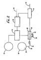
- Figure 2 shows a system on the invention comprising a pneumatic pressure supply 32 which is connected through a pressure modulator 44 to a pneumatic-to-hydraulic booster 26.
- the booster 26 comprises two coupled pistons 28 and 30 and a cylinder 34 containing liquid 39 which is forced from the booster by a pressure which is controlled by varying the pneumatic pressure applied to the piston 28.
- the gain of the booster is proportional to the ratio of the first piston area to the second piston area.
- the cylinder 34 can be refilled by withdrawing the second piston 30 and pulling fresh liquid from a liquid supply 38 through a liquid inlet 37 and a check valve 36.
- the flow rate of the liquid is measured by a flowmeter 14 and is input to a servo-loop controller 40.
- a desired flow rate is input to the servo-loop controller 40 through a set-point input 42.
- the servo-loop controller 40 then compares the measured flow rate to the desired flow rate and, if the measured flow rate does not equal the desired flow rate, instructs the pressure modulator 44 to adjust the pneumatic pressure to the first piston 28 of the booster 26 to achieve the desired liquid flow rate.
- the liquid source 38, the check valve 36, the pressure supply 32, the pressure modulator 44, and the pneumatic-to-hydraulic booster 26 can make up one of the variable pressure liquid supplies 12 of Fig. 1 .
- the servo-loop controller 40 and set-point input 42 can make up the controller 18 of Fig. 1 .
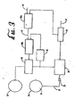
- Figure 3 shows a system similar to that shown in Figure 2 , but employing two nested servo loops as the controller.
- An outer servo-loop 40a compares the measured flow rate to the desired flow rate then outputs a pressure setpoint 43 to an inner servo-loop 40b.
- a gas pressure sensor 46 measures the pneumatic pressure applied to the first piston 28 of the booster 26. The measured pneumatic pressure is input to the inner servo-loop 40b controller as well as the pressure setpoint 43 from the outer servo-loop controller 40a. If the measured flow rate is not the desired flow rate, the inner servo-loop 40b instructs the pressure modulator 44 to adjust the pneumatic pressure applied to the first piston 28 of the booster 26.
- Figure 4 shows a system similar to that shown in Figure 3 in which one of the inner servo-loop 40b inputs is the measured liquid pressure from a liquid pressure sensor 48 located between the booster 26 and the flowmeter 14.
- Figure 5 shows a system similar to that shown in Figure 3 in which the flowmeter 14 comprises a capillary tube 50 and first and second pressure sensors 48a and 48b, located at either end of the tube.
- the flow rate is calculated using the measured pressure difference across the known flow conductance of the tube 50.
- the first pressure sensor 48a of the flowmeter 14 can provide input to the inner servo-loop 40b.
- two (or more) systems of the invention each of which may be as described in one of Figures 2-5 and which may be the same or different, can supply different liquids which are mixed before they reach the liquid outlet.
- the systems can, if appropriate, share one or more components. For example, when two systems as shown in Figure 5 are used, they can make use of a shared pressure sensor 48b.
- a system as shown in Figure 5 was prepared, and the setpoint was set to a constant value of 2700 nL/min over 50 minutes.
- the pressure modulator 44 was an electro-pneumatic controller Control Air 900-EHD
- the pneumatic-to-hydraulic booster 26 was Haskel MS-36
- the pump liquid was deionized water.
- Each of the pressure sensors 48a and 48b was an Entran EPX transducer. The transducers were at either end of a 10 cm length of a 10 ⁇ m ID capillary tube 50. The pressure drop across the capillary tube was about 690 kPa (100 psi).
- the flow rate was calculated by a microprocessor.
- the resulting metered flow of liquid was accurate within 0.02 %> of its setpoint over a period of 50 minutes, i.e. a flow rate accuracy of 0.56 nL/min RMS.
- a system was prepared using two systems as shown in Figure 5 connected to the same liquid outlet, and sharing a pressure sensor 48b.
- the flow profile was a 20 minute constant gradient delivery of the first and second liquids, which were water and acetonitrile, varying between 100 and 300 nL/min, with a 1 minute period of constant flow at the beginning and end of the test.
- the two liquids were mixed in concentrations ranging from 25% to 75% over the duration of the test, and at a total constant flow rate of 400 nL/min into the column.
- the measured flow rate from each controller indicated accuracy within 0.28 nL/min RMS of the setpoint over the full range of the test conditions.
Description
- The invention relates to systems in which liquids flow at low rates, in particular at rates of less than about 100 microliters/minute. There is increasing interest in such systems, because they reduce sample sizes, reduce waste, and improve compatibility with other systems, for example High Performance Liquid Chromatography ("HPLC") systems.
- Conventional pumping systems, which operate at relatively high flow rates, e.g. at least 0.1 ml/min, are described in for example J. Chrom. Sci., 12, 425, 432 (1974) by Mcnair et al, Rev. Sci. Instrum. 62, 1642-1646 (1991) by LeBlanc, and
U.S. Patent No. 5,777, 213 (Tsukazaki ). Such systems do not provide precise control at low flow rates, and respond slowly to adjustment of the flow rate. When such systems are used to produce low flow rates, the conventional procedure is to split off a small proportion of a much larger liquid flow (see for example Journal of Chromatography A, 856, 117-113 (1999) by Vissers). -
US 5294929 A discloses a liquid chromatography method and apparatus where liquid is pumped from a chamber to an outlet under pressure. The liquid pressure is monitored at the outlet and then compared with a set point pressure. This information is used to control the pressure of the liquid at the outlet. -
DE 19625648 A discloses a supercritical fluid chromatography system that employs a pneumatic amplifier pump, a pressure regulator and an electronic pressure control system. -
US 3917531 A discloses a conventional liquid chromatography system which employs a pneumatic amplifier pump, a pressure regulator and a pressure control system. - The invention is defined in claims 1 and 17, respectively. Particular embodiments are set out in the dependent claims.
- The present invention provides a method and an apparatus for delivering liquids at low flow rates, for example in the range of about 1 nanoliter/minute to about 100 microliters/minute, and, if desired, varying the flow rate in a controlled manner.
- This invention provides a method of supplying a liquid to a liquid outlet at a flow rate of less than about 100 microliters/minute, the method comprising
- 1) applying pressure from a first pressure source to a first liquid, thus causing the first liquid to flow through a first conduit;
- 2) detecting a first measured rate at which the first liquid is flowing through the first conduit;
- 3) comparing the first measured rate with a first desired rate of flow of the first liquid through the first conduit; and
- 4) using information obtained in step 3 to adjust the pressure applied to the first liquid by the first pressure source to adjust the rate at which the first liquid flows through the first conduit towards the first desired rate of flow;
- The method preferably having at least one of the following further characteristics:
- 5) applying pressure from a second pressure source to a second liquid, thus causing the second liquid to flow through a second conduit;
- 6) detecting a second measured rate at which the second liquid is flowing through the second conduit;
- 7) comparing the second measured rate with a second desired rate of flow of the second liquid through the second conduit;
- 8) using information obtained in step 7 to adjust the pressure applied to the second liquid by the second pressure source to adjust the rate at which the second liquid flows through the second conduit towards the second desired rate of flow;
- 9) mixing the first liquid from the first conduit with the second liquid from the second conduit; and
- 10) supplying the mixture obtained in step 9 to the liquid outlet.
- The invention further provides an apparatus suitable for use in the method of the invention, this term being used to include liquid-filled apparatus which is in use, apparatus which must be filled with one or more liquids before it can be used, and novel components which must be assembled with other components before such apparatus is obtained.
- The invention is illustrated in the accompanying schematic drawings, in which
- Figure 1
- shows a system whose liquid outlet is connected, through an injection valve, to a separation column; and
- Figure 2-5
- show different systems using different methods to control the flow of the liquid.
- Therein
Figures 1-2 serve for illustrating background of the invention andFigures 3-5 relate to embodiments of the invention. - In the Summary of the Invention above and in the Detailed Description of the Invention, the Examples, and the claims below, and in the accompanying drawings, reference is made to particular features of the invention. It is to be understood that the disclosure of the invention in this specification includes all appropriate combinations of such particular features. For example, where a particular feature is disclosed in the context of a particular aspect or embodiment of the invention, or a particular Figure, or a particular claim, that feature can also be used, to the extent appropriate, in combination with and/or in the context of other particular aspects and embodiments of the invention, and in the invention generally.
- The term "comprises", and grammatical equivalents thereof, are used herein to mean that other components, ingredients, steps etc. are optionally present in addition to the component(s), ingredient(s), step(s) specifically listed after the term "comprises". The term "at least" followed by a number is used herein to denote the start of a range beginning with that number (which may be a range having an upper limit or no upper limit, depending on the slope, or any of the other forms known in the separation arts. Flow controllers and servo loops can be combined to provide more complicated liquid composition variations.
- The delay volume of the system, i.e. the volume of the liquid or mixture of liquids after the desired conditions (e.g. a mixture containing the liquids in the desired ratio) have been established and before the liquid is discharged from the liquid outlet, is preferably small, so that desired changes in the discharged liquid take place with little delay. The delay volume may be for example less than 1 microliter or 100 nL.
- Any flow meter operating efficiently at the desired flow rates can be used to determine the rates at which the liquid is flowing through the conduit. Preferably the flowmeter provides a continuous signal over the whole range of desired flow rates, including liquid flow in both directions. Preferably the signal bandwidth of the flowmeter, i.e. the frequency corresponding to the minimum time between meaningful readings, is faster than 1 Hertz, particularly faster than 10 Hertz. Known flow meters include those disclosed in J. MEMS, 6, 119-125 (1997), by Enoksson et al.; thermal mass flow meters; thermal heat tracers as disclosed in
US Patent No. 6,386,050 ; optical flow meters, for example those disclosed in Appl. Opt., 33, 6073-6077 (1994) by Carvalho et al. - A preferred flowmeter comprises a capillary tube through which the liquid flows, and one or more pressure sensors which measure the pressure drop across the capillary tube, either directly or by measuring the pressures at the ends of the tube and subtracting one measurement from the other. A capillary tube has a high hydraulic resistance, but a very low liquid volume, allowing rapid response. The capillary tube can be part of the conduit through which the liquid flows. The pressure sensor can be a pressure transducer, preferably one having a volume of at most 5 microliters. Preferably, the length and diameter of the capillary tube are such that the pressure drop across it is at least one of (a) 345 kPa (50 psi) and (b) at least 5% of the pressure applied to the liquid by the pressure source. The diameter of the capillary tube can be for example 35 to 65 microns, for example about 50 microns. Flow rates can be calculated in known manner from knowledge of the dimensions of the capillary tube and the properties of the liquid. For example, when the liquid is water, a pressure drop of about 3100 kPa (450 psi) through a capillary tube having a length of 10 cm and an internal diameter of 10 microns, indicates a flow rate of about 500 nL/min.
- Any pressure source can be used to drive the liquid or liquids in the system of the invention. Suitable pressure sources include electrokinetic pumps (e.g. as disclosed in
US Patent No. 5,942,093 ), electrokinetic flow controllers (e.g. as disclosed inU.S. Patent application serial Nos. 09/942,884 and10/155,474 - Some embodiments of the invention make use of pressure sources comprising a pneumatic-to-hydraulic booster in liquid connection with the liquid supply. Any known booster can be used, including a liquid head that uses a dynamic seal on a moving solid rod that displaces liquid, the rod being coupled to the shaft of a conventional pneumatic piston. The gain of the booster is typically greater than 1, but may also be equal to 1 (direct transfer of pressure with no amplification) or less than 1 for lower pressure applications.
- There may be a check valve between the liquid supply and the booster so that liquid cannot flow from the booster to the liquid supply. There may be a pressure modulator between the primary power source, e.g. a pneumatic pressure source, and the booster. Any known pressure modulator can be used, including an electro-pneumatic controller in which an input current or voltage produces a command signal to one or more actuators within the controller. The actuator generally acts to increase or decrease the amount of air flow through the electro-pneumatic controller in order to maintain an output pressure proportional to the command signal. The system can include at least one servo-loop which is located between the flowmeter measuring the flow rate of the liquid and the pressure modulator, which compares the measured and desired flow rates, and which instructs the pressure modulator to adjust the pneumatic pressure supply so that the liquid flows at the desired rate.
- Preferably, any change in the rates at which the first liquid flows through the first conduit results only from a change in the pressure applied to the first liquid by the first pressure source, and does not involve any mechanical change of the system. This feature, in combination with the fact that the measured flow rate is used to control the pressure applied to the liquid, reduces variability introduced by factors (if present all) such as check valve leakage, pump seal leakage, flexing and creep of mechanical seals, thermal expansion of components, and compression of liquids. When there are two (or more) liquids, the pressure sources controlling the liquid flows can be the same or different. Preferably the pressure source is continuously variable, is capable of providing flow rates in the range of 1 nL/minute to 10 µl/minute or 100 µl/minute into, for example, back pressures from about 100 kPa (1 atmosphere) up to 34500 kPa (5000 psi) or higher, e.g. 69000 kPa (10000 psi), and has a response time of seconds or less, e.g. less than 1 second, thus allowing rapid changes in flow rates. In electrokinetic pumps and flow controllers, the hydraulic resistance is high, but the compressible volume is very low, resulting in very rapid changes. Pneumatic booster pressure supplies have larger volumes, but the pistons have very low resistance to volumetric changes, once again allowing very rapid changes.
- The measured and desired liquid flow rates can be compared in any operable way, and the results used to control the pressure source(s) in any operable way. Preferably, the liquid flow rates are adjusted to compensate for volumetric changes of the mixture which will affect the flow rate. For example, the system can make use of a controller which computes the physical properties of the liquid upon which the volume depends, such as composition, temperature and pressure. For example, the composition and mixing ratio of both liquids can be input to the controller; the flowmeter can measure the pressure; and a thermocouple in communication with the controller can take the temperature measurement. Alternatively, the system can be temperature-controlled and the temperature communicated to the controller.
- In some embodiments of the invention, at least one servo-loop controller (abbreviated herein to servo-loop) is used to control the liquid flows. The servo-loop can be of any type known in the art for example a PID loop, and can be constructed, for example, using discrete analog circuits, discrete digital circuits, dedicated microprocessors or a computer. In one class of such embodiments, the pressure source comprises a pneumatic pressure source, a pneumatic-to-hydraulic booster, and a pressure modulator which is located between the pneumatic pressure supply and the booster and which controls the amounts of pneumatic pressure supplied to the booster; the detection of the measured flow rate is carried out by a first flowmeter which measures the rate at which the liquid flows from the booster to the liquid outlet; and the comparison of the measured and desired rates of flow, and the use of the information obtained from that comparison to adjust the pressure applied to the liquid by the pressure source, are carried out by a servo-loop. In another class of such embodiments, the pressure source comprises a pneumatic pressure source, a pneumatic-to-hydraulic booster, a pressure modulator which is located between the pneumatic pressure supply and the booster and which controls the pneumatic pressure supplied to the booster, and a pressure sensor which is located between the pneumatic pressure supply and booster; the detection of the measured rate of liquid flow is carried out by a first flowmeter which measures the rate at which the liquid flows from the first booster to the liquid outlet; the comparison of the measured and desired flow rates is carried out by a combination of an inner servo-loop which communicates with the pressure sensor and the first pressure modulator, and an outer servo-loop which communicates with the flowmeter and the inner servo-loop, the outer servo-loop comparing the measured and desired flowrates and outputting a first pressure set point to the first inner servo-loop, and the inner servo-loop instructing the pressure modulator to adjust the pneumatic pressure supply.
- It is desirable that the system should have a rapid response time, i.e. should respond rapidly to pressure changes initiated by changes in the desired flow rate. The term "response time" is used herein to denote the time taken to reach a flow rate which is within 5% of the desired flow rate. Preferably, the system has a response time of less than 1 second, particularly less than 0.6 second, even when there is a substantial change in the desired flow rate, for example a change from a first desired flowrate to a second desired flow rate which is from 0.3 to 3 times, preferably from 0.2 to 5 times, the first desired flow rate.
- The time response of the system can be understood in terms of the hydraulic resistances and capacitances. As with an electronic circuit, the product of these two gives a characteristic time constant. The hydraulic capacitance in the disclosed systems is dominated by the volumes and compressibility of the liquid, but also includes contributions from sources such as the deflection of a diaphragm in a pressure transducer.
- The capillary flow meter described previously has a reasonably high hydraulic resistance, but a very low liquid volume, allowing rapid response. The compressible liquid volume (leading to capacitance) in the systems shown in the Figures is preferably on the order of 5 microliters and is due to the pressure transducer mounting.
- The liquid outlet of the systems of the invention can be connected to any further liquid flow system requiring a low- volume liquid supply. Such further systems include for example gradient HPLC systems, mass spectrometer systems, flow injection systems, analysis systems, drug delivery systems, and chemical reactor systems. Many suitable further systems include columns with diameters from 50 µm to 1 mm (often referred to as capillary columns). The output of the column can be supplied to a detector. The detector can be for example a laser-induced fluorescence detector, an optical absorption detector, a refractive index or electrochemical detector, a mass spectrometer, or NMR spectrometer, or any other detector known in the HPLC arts. The liquid flow rate in capillary systems typically ranges up from nanoliters per minute ("nL/min") to 100 microliters per minute ("µl/min") and may be less than 10 microliters per minute. Precise control of the flow rate in such systems is important, for example so that analyte retention times (and, therefore, analyte identification) can be reliably predicted, and so that false analyte signals can be avoided.
- Flow control is particularly important for gradient separations, in which the liquid composition is varied during the course of the separation. In gradient HPLC, the liquid outputs from two (or more) sources are combined to provide a desired flow rate of known and varying composition.
- Two or more systems of the invention can be run in parallel from common sources of liquids to perform multiple operations, for example separations, in parallel.
-
Figure 1 shows a system of the invention comprising two variable pressure liquid supplies 12, each supplying a liquid 39 (the liquids from the two supplies being different), and aflowmeter 14 for each liquid 39. After passing through the flow meters, the liquids are mixed together, and the mixture exits through aliquid outlet 16. Each of the flow meters sends signals to a controller 18, which adjusts the pressures of the liquid supplies 12 so that the mixture contains desired proportions of theliquids 39 and flows out of theliquid outlet 16 at a desired flow rate less than 100 microliters/minute, for example less than 10 microliters/minute. Theliquid outlet 16 is connected through an injection valve 20 to an HPLC separation column 22. -
Figure 2 shows a system on the invention comprising apneumatic pressure supply 32 which is connected through apressure modulator 44 to a pneumatic-to-hydraulic booster 26. Thebooster 26 comprises two coupledpistons cylinder 34 containingliquid 39 which is forced from the booster by a pressure which is controlled by varying the pneumatic pressure applied to thepiston 28. The gain of the booster is proportional to the ratio of the first piston area to the second piston area. Thecylinder 34 can be refilled by withdrawing thesecond piston 30 and pulling fresh liquid from aliquid supply 38 through aliquid inlet 37 and acheck valve 36. The flow rate of the liquid is measured by aflowmeter 14 and is input to a servo-loop controller 40. A desired flow rate is input to the servo-loop controller 40 through a set-point input 42. The servo-loop controller 40 then compares the measured flow rate to the desired flow rate and, if the measured flow rate does not equal the desired flow rate, instructs thepressure modulator 44 to adjust the pneumatic pressure to thefirst piston 28 of thebooster 26 to achieve the desired liquid flow rate. - The
liquid source 38, thecheck valve 36, thepressure supply 32, thepressure modulator 44, and the pneumatic-to-hydraulic booster 26 can make up one of the variable pressure liquid supplies 12 ofFig. 1 . The servo-loop controller 40 and set-point input 42 can make up the controller 18 ofFig. 1 . -
Figure 3 shows a system similar to that shown inFigure 2 , but employing two nested servo loops as the controller. An outer servo-loop 40a compares the measured flow rate to the desired flow rate then outputs apressure setpoint 43 to an inner servo-loop 40b. A gas pressure sensor 46 measures the pneumatic pressure applied to thefirst piston 28 of thebooster 26. The measured pneumatic pressure is input to the inner servo-loop 40b controller as well as thepressure setpoint 43 from the outer servo-loop controller 40a. If the measured flow rate is not the desired flow rate, the inner servo-loop 40b instructs thepressure modulator 44 to adjust the pneumatic pressure applied to thefirst piston 28 of thebooster 26. -
Figure 4 shows a system similar to that shown inFigure 3 in which one of the inner servo-loop 40b inputs is the measured liquid pressure from aliquid pressure sensor 48 located between thebooster 26 and theflowmeter 14. -
Figure 5 shows a system similar to that shown inFigure 3 in which theflowmeter 14 comprises a capillary tube 50 and first and second pressure sensors 48a and 48b, located at either end of the tube. The flow rate is calculated using the measured pressure difference across the known flow conductance of the tube 50. In another arrangement, the first pressure sensor 48a of theflowmeter 14 can provide input to the inner servo-loop 40b. - Wherein a controlled mixture of liquids is require, two (or more) systems of the invention, each of which may be as described in one of
Figures 2-5 and which may be the same or different, can supply different liquids which are mixed before they reach the liquid outlet. The systems can, if appropriate, share one or more components. For example, when two systems as shown inFigure 5 are used, they can make use of a shared pressure sensor 48b. - A system as shown in
Figure 5 was prepared, and the setpoint was set to a constant value of 2700 nL/min over 50 minutes. In this system, thepressure modulator 44 was an electro-pneumatic controller Control Air 900-EHD, the pneumatic-to-hydraulic booster 26 was Haskel MS-36, and the pump liquid was deionized water. Each of the pressure sensors 48a and 48b was an Entran EPX transducer. The transducers were at either end of a 10 cm length of a 10 µm ID capillary tube 50. The pressure drop across the capillary tube was about 690 kPa (100 psi). The flow rate was calculated by a microprocessor. The resulting metered flow of liquid was accurate within 0.02 %> of its setpoint over a period of 50 minutes, i.e. a flow rate accuracy of 0.56 nL/min RMS. - A system was prepared using two systems as shown in
Figure 5 connected to the same liquid outlet, and sharing a pressure sensor 48b. The flow profile was a 20 minute constant gradient delivery of the first and second liquids, which were water and acetonitrile, varying between 100 and 300 nL/min, with a 1 minute period of constant flow at the beginning and end of the test. Thus, the two liquids were mixed in concentrations ranging from 25% to 75% over the duration of the test, and at a total constant flow rate of 400 nL/min into the column. The measured flow rate from each controller indicated accuracy within 0.28 nL/min RMS of the setpoint over the full range of the test conditions.
wherein alternatively a liquid pressure sensor is located between the first booster and the first flowmeter, and the first inner servo loop communicates with the liquid pressure sensor and the first pressure modulator.
Claims (18)
- A method of supplying a liquid to a liquid outlet (16) at a flow rate of less than 100 micro liters/minute, the method comprising1) applying pressure from a first pressure source (12) to a first liquid (39), thus causing the first liquid to flow through a first conduit;2) detecting a first measured rate at which the first liquid is flowing through the first conduit;3) comparing the first measured rate with a first desired rate of flow of the first liquid through the first conduit; and4) using information obtained in step 3 to adjust the pressure applied to the first liquid by the first pressure source (12) to adjust the rate at which the first liquid flows through the first conduit towards the first desired rate of flow;wherein the first pressure source (12) comprises a first pneumatic-to-hydraulic booster (26), a first pneumatic pressure source (32) and a first pressure modulator (44) which is located between the first pneumatic pressure source (32) and the first booster (26) and which controls the amount of pneumatic pressure supplied to the first booster (26); and
wherein step 2 is carried out by a first flowmeter (14) which measures the rate at which the first liquid flows from the first booster (26) to the liquid outlet (16),
characterized in that
a gas pressure sensor (46) is located between the first pneumatic pressure source (32) and the first booster (26), or a liquid pressure sensor (48) is located between the first booster (26) and the flowmeter (14);
wherein steps 3 and 4 are carried out by a combination ofa first inner servo-loop (40b) which communicates with the gas pressure sensor (46) or the liquid pressure sensor (48) and with the first pressure modulator (44), anda first outer servo-loop (40a) which communicates with the first flowmeter (14) and the first inner servo-loop (40b),the first outer servo-loop (40a) comparing the first measured flowrate to the first desired flowrate and outputting a first pressure set point to the first inner servo-loop (40b), and the first inner servo-loop (40b) instructing the first pressure modulator (44) to adjust the first pneumatic pressure source (32). - A method according to claim 1, wherein the first conduit has a diameter of between 10 µm and 65 µm and the first liquid is supplied to the liquid outlet (16) at a flow rate of less than 100 micro liters/minute.
- A method according to claim 1 or 2, wherein the method includes:5) applying pressure from a second pressure source (12) to a second liquid (39), thus causing the second liquid to flow through a second conduit;6) detecting a second measured rate at which the second liquid is flowing through the second conduit;7) comparing the second measured rate with a second desired rate of flow of the second liquid through the second conduit;8) using Information obtained in step 7 to adjust the pressure applied to the second liquid by the second pressure source (12) to adjust the rate at which the second liquid flows through the second conduit towards the second desired rate of flow;9) mixing the first liquid from the first conduit with the second liquid from the second conduit; and10) supplying the mixture obtained in step 9 to the liquid outlet (16);
- A method according to any one of claims 1 to 3, wherein the system has a response time, when the desired rate changes from a first value equal to the first measured rate to a second value which is from 0.2 to 5 times the first measured rate, of less than 1 second.
- A method according to any one of claims 1 to 4, wherein step 2 is carried out using the flowmeter (14) comprising(i) a first capillary tube whose length and diameter are such that the pressure drop across the first capillary tube (50) is at least one of (a) 350kPa (50 psi) and (b) at least 5% of the pressure applied to the first liquid by the first pressure source (32), and(ii) first and second pressure sensors (48a-b) which measure the pressure drop across the first capillary tube (50).
- A method according to claim 5, wherein the capillary tube (50) is part of the first conduit.
- A method according to any of claims 1 to 6, wherein any change in the rate at which the first liquid flows through the first conduit (16) results solely from a change in the pressure applied to the first liquid by the first pressure source (32).
- A method according to any of claims 3 to 7, wherein the second pressure source (32) comprises e second pneumatic-to-hydraulic booster (26), and step 8 is carried out by a servo-loop (40) connected to the second booster (26).
- A method according to any of claims 3 to 7, wherein the second pressure source (12) comprises
a second pneumatic pressure source (32), a second pneumatic-to-hydraulic booster (26), and a second pressure modulator (44) which is located between the second pneumatic pressure source (32) and the second booster (26) and which controls the amounts of pneumatic pressure supplied to the second booster (26);
wherein step 6 is carried out by a second flowmeter (14) which measures the rate at which the second liquid flows from the second booster (26) to the liquid outlet (16); and
wherein steps 7 and 8 are carried out by a second inner servo-loop (40a) which instructs the second pressure modulator (44). - A method according to any of claims 3 to 7, wherein
the second pressure source (12) comprises a second pneumatic pressure source (32), a second pneumatic-to-hydraulic booster (26), a second pressure modulator (44) which is located between the second pneumatic pressure source (32) and the second booster (26) and which controls the pneumatic pressure supplied to the second booster (26), and a second pressure sensor (46) which is located between the second pneumatic pressure source (32) and the second booster (26);
wherein step 6 is carried out by a second flowmeter (14) which measures the rate at which the second liquid flows from the second booster (26) to the liquid outlet (16); and
wherein steps 7 and 8 are carried out by a combination of a second inner servo-loop (40b) which communicates with the second pressure sensor (46) and the second pressure modulator (44), and a second outer servo-loop (40a) which communicates with the second flowmeter (14) and the second inner servo-loop (40b), the second outer servo-loop (40a) comparing the second measured flowrate to the second desired flowrate and outputting a second pressure set point to the second inner servo-loop (40b), and the second inner servo-loop (40b) instructing the second pressure modulator (44) to adjust the second pneumatic pressure source (32). - A method according to any of claims 3 to 7, wherein the second pressure source (32) comprises pressure generated by an electrokinetic pump or an electrokinetic flow controller or both.
- A method according to any of claims 3 to 11, wherein the time taken to adjust the flow rate of the second liquid from the second measured rate to the second desired rate is less than 1 second.
- A method according to any of claims 3 to 12, wherein step 6 is carried out using the flowmeter (14) comprising(i) a second capillary tube (50) whose length and diameter are such that the pressure drop across the second capillary tube (50) is at least one of (a) 350kPa (50 psi) and (b) at least 5% of the pressure applied to the second liquid by the second pressure source, and(ii) first and second pressure sensors (48a-b) which measure the pressure drop across the second capillary tube (50).
- A method according to any of claims 3 to 13, wherein the first and second desired flow rates vary as a function of time, and the sum of the first and second desired flow rates remains substantially constant.
- A method according to any one of claims 1 to 14, wherein the liquid is supplied to the liquid outlet (16) at the flow rate of less than 10 microliters/minute.
- A method according to any one of claims 1 to 15, wherein the liquid outlet (16) is in fluid communication with a liquid chromatography column having a diameter of between 50 µm and 1 mm.
- An apparatus suitable for carrying out the method of any of claims 1 to 16, the apparatus comprising(a) first and second liquid inlets (37) of respective first and second liquid conduits;(b) a liquid outlet (16) in liquid communication with the first and second liquid inlets;(c) first and second pneumatic pressure sources (32);(d) a first pneumatic-to-hydraulic booster (26) located between the first liquid inlet (37) and the liquid outlet (16) and in operative communication with the first pneumatic pressure source (32), whereby the first pneumatic to hydraulic booster (26) forces liquid out through the liquid outlet (16);(e) a second pneumatic-to-hydraulic booster (26) located between the second liquid inlet (37) and the liquid outlet (16) and in operative communication with the second pneumatic pressure source (32), whereby the second pneumatic to hydraulic booster (26) forces liquid out through the liquid outlet (16);(f) a first pressure modulator (44) located between the first pneumatic pressure source (32) and the first pneumatic to hydraulic booster (26), wherein the first pressure modulator (44) controls the amount of pneumatic pressure supplied to the first pneumatic-to-hydraulic booster (26);(g) a second pressure modulator (44) located between the second pneumatic pressure source (32) and the second pneumatic to hydraulic booster (26), whereby the second pressure modulator (44) controls the amount of pneumatic pressure supplied to the second pneumatic to hydraulic booster (26);(h) a first flowmeter (14) which is located between the first pneumatic-to-hydraulic booster (26) and the liquid outlet (16) and which can measure the flow rate of a first liquid flowing from the first booster (26) to the liquid outlet (16);(i) a second flowmeter (14) which is located between the second pneumatic-to-hydraulic booster (26) and the liquid outlet (16) and which can measure the flow rate of a second liquid flowing from the second booster (26) to the liquid outlet (16);(j) a first outer servo-loop controller (40a) in communication with the first flowmeter (14) and the first pressure modulator (44), whereby the first outer servo-loop controller (40a) compares the measured flow rate of the first liquid to a first desired flow rate and instructs the first pressure modulator (44) to adjust the first pneumatic pressure source (32) so that the first liquid flows out of the liquid outlet (16) at the first desired flow rate;(k) a second outer servo-loop controller (40a) in communication with the second flowmeter (14) and the second pressure modulator (44), whereby the second outer servo- loop controller (40a) compares the measured flow rate of the second liquid to a second desired flow rate and instructs the second pressure modulator (44) to adjust the second pneumatic pressure source (32) so that the second liquid flows out of the liquid outlet (16) at the first desired flow rate;the apparatus further comprising:a gas pressure sensor (46) located between the first pneumatic pressure source (32) and the first pneumatic to hydraulic booster (26), or a liquid pressure sensor (48) located between the first booster (26) and the flowmeter (14), anda first inner servo-loop controller (40b) in communication with the first pressure sensor (46) or the liquid pressure sensor (48) and with the first pressure modulator (44),wherein the first outer servo-loop controller (40a) outputs to the first inner servo-loop controller (40b) a first pneumatic pressure set point based on a comparison of the measured flow rate of the first liquid with the first desired flow rate, and wherein the first inner servo-loop controller (40b) instructs the first pressure modulator (44) to adjust the first pneumatic pressure source (32) if the first measured flow rate is not the first desired flow rate;a gas pressure sensor (46) located between the second pneumatic pressure source (32) and the second pneumatic to hydraulic booster (26), or a liquid pressure sensor (48) is located between the first booster (26) and the flowmeter (14), anda second inner servo-loop controller (40b) in communication with the second pressure sensor (46) or the liquid pressure sensor (48) and with the second pressure modulator (44),wherein the second outer servo-loop controller (40a) outputs to the second inner servo-loop controller (40b) a second pneumatic pressure set point based on a comparison of the measured flow rate of the second liquid with the second desired flow rate, and wherein the second inner servo-loop controller (40b) instructs the second pressure modulator (44) to adjust the second pneumatic pressure source (32) if the second measured flow rate is not the second desired flow rate.
- An apparatus according to claim 17, wherein the liquid outlet (16) is in communication with a liquid chromatography column having a diameter between 50 µm and 1 mm.
Applications Claiming Priority (3)
| Application Number | Priority Date | Filing Date | Title |
|---|---|---|---|
| US246284 | 2002-09-17 | ||
| US10/246,284 US7465382B2 (en) | 2001-06-13 | 2002-09-17 | Precision flow control system |
| PCT/US2003/030008 WO2004027535A1 (en) | 2002-09-17 | 2003-09-17 | Flow control system |
Publications (2)
| Publication Number | Publication Date |
|---|---|
| EP1540437A1 EP1540437A1 (en) | 2005-06-15 |
| EP1540437B1 true EP1540437B1 (en) | 2013-11-06 |
Family
ID=32028952
Family Applications (1)
| Application Number | Title | Priority Date | Filing Date |
|---|---|---|---|
| EP03759457.9A Expired - Lifetime EP1540437B1 (en) | 2002-09-17 | 2003-09-17 | Flow control system |
Country Status (6)
| Country | Link |
|---|---|
| US (1) | US7465382B2 (en) |
| EP (1) | EP1540437B1 (en) |
| JP (1) | JP4854197B2 (en) |
| AU (1) | AU2003275188A1 (en) |
| CA (1) | CA2498034C (en) |
| WO (1) | WO2004027535A1 (en) |
Families Citing this family (46)
| Publication number | Priority date | Publication date | Assignee | Title |
|---|---|---|---|---|
| US20020189947A1 (en) * | 2001-06-13 | 2002-12-19 | Eksigent Technologies Llp | Electroosmotic flow controller |
| US20030098661A1 (en) * | 2001-11-29 | 2003-05-29 | Ken Stewart-Smith | Control system for vehicle seats |
| US7305925B2 (en) * | 2002-07-05 | 2007-12-11 | Gaspardo Seminatrici S.P.A. | Volumetric metering device for the metered delivery of granular and powdery materials particulary for machines for distributing such materials |
| US7517440B2 (en) * | 2002-07-17 | 2009-04-14 | Eksigent Technologies Llc | Electrokinetic delivery systems, devices and methods |
| US7235164B2 (en) * | 2002-10-18 | 2007-06-26 | Eksigent Technologies, Llc | Electrokinetic pump having capacitive electrodes |
| US7364647B2 (en) * | 2002-07-17 | 2008-04-29 | Eksigent Technologies Llc | Laminated flow device |
| US6962658B2 (en) * | 2003-05-20 | 2005-11-08 | Eksigent Technologies, Llc | Variable flow rate injector |
| US20060186028A1 (en) * | 2004-02-06 | 2006-08-24 | Micromass Uk Limited | Mass spectrometer |
| US7559356B2 (en) * | 2004-04-19 | 2009-07-14 | Eksident Technologies, Inc. | Electrokinetic pump driven heat transfer system |
| GB2429785B (en) | 2004-05-21 | 2009-11-18 | Waters Investments Ltd | Closed loop flow control of a hplc constant flow pump to enable low-flow operation |
| GB2454783B (en) * | 2004-05-21 | 2009-10-28 | Waters Investments Ltd | HPLC constant flow pump to enable low-flow operation, wherein thermal-based sensors are contained within an isothermal block |
| JP2008507033A (en) * | 2004-07-13 | 2008-03-06 | ウオーターズ・インベストメンツ・リミテツド | High pressure pump controller |
| US7670480B2 (en) * | 2005-03-31 | 2010-03-02 | Agilent Technologies, Inc. | Solvent supply with correction of piston movement |
| DE602005025974D1 (en) * | 2005-03-31 | 2011-03-03 | Agilent Technologies Inc | Apparatus and method for providing solvents with correction of piston movement |
| US7458520B2 (en) * | 2005-04-19 | 2008-12-02 | Masco Corporation Of Indiana | Electronic proportioning valve |
| US7475827B2 (en) * | 2005-04-19 | 2009-01-13 | Masco Corporation Of Indiana | Fluid mixer |
| US7448553B2 (en) * | 2005-04-19 | 2008-11-11 | Masco Corporation Of Indiana | Fluid mixer |
| WO2007030755A2 (en) * | 2005-09-09 | 2007-03-15 | Eksigent Technologies, Llc | Variable flow rate system for column chromatography |
| KR100697292B1 (en) * | 2005-10-04 | 2007-03-20 | 삼성전자주식회사 | Semiconductor device and method for forming thereof |
| EP1957793B1 (en) * | 2005-11-23 | 2013-01-16 | Eksigent Technologies, LLC | Electrokinetic pump designs and drug delivery systems |
| WO2007109157A2 (en) * | 2006-03-17 | 2007-09-27 | Waters Investments Limited | Solvent delivery system for liquid chromatography that maintains fluid integrity and pre-forms gradients |
| US7516658B2 (en) | 2006-09-29 | 2009-04-14 | Rosemount Inc. | Electro-kinetic pressure/flow sensor |
| US7867592B2 (en) | 2007-01-30 | 2011-01-11 | Eksigent Technologies, Inc. | Methods, compositions and devices, including electroosmotic pumps, comprising coated porous surfaces |
| WO2009076134A1 (en) * | 2007-12-11 | 2009-06-18 | Eksigent Technologies, Llc | Electrokinetic pump with fixed stroke volume |
| EP2249939B1 (en) | 2008-02-06 | 2017-05-10 | Proseon Biosystems A/S | Flow control in high performance liquid chromatography |
| US8794052B2 (en) * | 2009-04-16 | 2014-08-05 | Shimadzu Corporation | Liquid chromatograph |
| US8746270B2 (en) * | 2010-02-10 | 2014-06-10 | Brg Industries Incorporated | Precision low flow rate fluid delivery system and methods for controlling same |
| JP6014588B2 (en) | 2010-06-23 | 2016-10-25 | ジーイー・ヘルスケア・バイオサイエンス・アクチボラグ | Method for producing a liquid mixture |
| US8550794B2 (en) * | 2010-08-09 | 2013-10-08 | Foothill Land, Llc | Double acting fluid pump |
| US8729502B1 (en) | 2010-10-28 | 2014-05-20 | The Research Foundation For The State University Of New York | Simultaneous, single-detector fluorescence detection of multiple analytes with frequency-specific lock-in detection |
| WO2012151588A1 (en) * | 2011-05-05 | 2012-11-08 | Eksigent Technologies, Llc | Ganging electrokinetic pumps |
| CN103813814A (en) | 2011-05-05 | 2014-05-21 | 艾克西根特技术有限公司 | Gel coupling for electrokinetic delivery system |
| US9459239B2 (en) * | 2011-07-08 | 2016-10-04 | Agilent Technologies, Inc. | Intake monitoring for accurate proportioning |
| EP2626697B1 (en) | 2012-02-07 | 2018-10-31 | King Saud University | Liquid chromatography device |
| WO2015095590A1 (en) * | 2013-12-18 | 2015-06-25 | Eksigent Technologies Llc | System and method of control of a reciprocating electrokinetic pump |
| US9816971B2 (en) * | 2014-09-08 | 2017-11-14 | Waters Technologies Corporation | Controllable injector sample dilution for a liquid chromatography system |
| US9416777B2 (en) | 2014-09-26 | 2016-08-16 | Becton, Dickinson And Company | Control circuits for electrochemical pump with E-valves |
| US9664659B2 (en) * | 2014-11-05 | 2017-05-30 | Dresser, Inc. | Apparatus and method for testing gas meters |
| GB2538103B (en) * | 2015-05-08 | 2021-09-15 | Agilent Technologies Inc | Correcting sample metering inaccuracy due to thermally induced volume change in sample separation apparatus |
| US20170074256A1 (en) * | 2015-09-16 | 2017-03-16 | William Banko | Bi-Metallic Solar Water Filtration Pump |
| US10814062B2 (en) | 2017-08-31 | 2020-10-27 | Becton, Dickinson And Company | Reservoir with low volume sensor |
| JP6851953B2 (en) * | 2017-10-30 | 2021-03-31 | アークレイ株式会社 | Pump drive method |
| US11835975B2 (en) * | 2020-04-29 | 2023-12-05 | Univesal City Studios LLC | Multi-stage water effect system |
| CN113668019B (en) * | 2021-08-31 | 2022-05-13 | 广东嘉元科技股份有限公司 | Precise liquid preparation device of electrolytic copper foil equipment |
| WO2023062193A1 (en) * | 2021-10-14 | 2023-04-20 | Ovizio Imaging Systems NV/SA | Method for monitoring a liquid culture flow |
| CN116422222B (en) * | 2023-06-13 | 2023-09-01 | 福建德尔科技股份有限公司 | Flow control system for automatically mixing fluorine gas and nitrogen gas |
Citations (1)
| Publication number | Priority date | Publication date | Assignee | Title |
|---|---|---|---|---|
| US3917531A (en) * | 1974-02-11 | 1975-11-04 | Spectra Physics | Flow rate feedback control chromatograph |
Family Cites Families (103)
| Publication number | Priority date | Publication date | Assignee | Title |
|---|---|---|---|---|
| US2615940A (en) | 1949-10-25 | 1952-10-28 | Williams Milton | Electrokinetic transducing method and apparatus |
| US2644900A (en) | 1951-11-27 | 1953-07-07 | Jr Edward V Hardway | Electrokinetic device |
| US2644902A (en) | 1951-11-27 | 1953-07-07 | Jr Edward V Hardway | Electrokinetic device and electrode arrangement therefor |
| US2661430A (en) | 1951-11-27 | 1953-12-01 | Jr Edward V Hardway | Electrokinetic measuring instrument |
| US2995714A (en) | 1955-07-13 | 1961-08-08 | Kenneth W Hannah | Electrolytic oscillator |
| CA662714A (en) | 1958-11-28 | 1963-05-07 | Union Carbide Corporation | Electro-osmotic cell |
| CA692504A (en) | 1960-04-22 | 1964-08-11 | N. Estes Nelson | Electro-osmotic integrator |
| GB1122586A (en) | 1964-09-02 | 1968-08-07 | Mack Gordon | Electro-hydraulic transducer |
| US3544237A (en) | 1968-12-19 | 1970-12-01 | Dornier System Gmbh | Hydraulic regulating device |
| US3682239A (en) | 1971-02-25 | 1972-08-08 | Momtaz M Abu Romia | Electrokinetic heat pipe |
| JPS50116893A (en) * | 1974-02-28 | 1975-09-12 | ||
| US3923426A (en) | 1974-08-15 | 1975-12-02 | Alza Corp | Electroosmotic pump and fluid dispenser including same |
| US3921041A (en) | 1975-02-24 | 1975-11-18 | American Radionic | Dual capacitor |
| US4347131A (en) | 1981-04-28 | 1982-08-31 | Robert Brownlee | Liquid chromatographic pump module |
| US5040126A (en) | 1981-09-09 | 1991-08-13 | Isco, Inc. | Method for predicting steady-state conditions |
| US4638444A (en) | 1983-02-17 | 1987-01-20 | Chemical Data Systems, Inc. | Microprocessor-controlled back-pressure system for small volume chemical analysis applications |
| DE3577750D1 (en) | 1984-10-18 | 1990-06-21 | Hewlett Packard Gmbh | METHOD FOR TREATING A LIQUID IN A TUBE. |
| JPS61237717A (en) | 1985-04-15 | 1986-10-23 | Nippon Kokudo Kaihatsu Kk | Natural permeation work of chemical grout and plant therefor |
| US4684465A (en) | 1986-10-10 | 1987-08-04 | Combustion Engineering, Inc. | Supercritical fluid chromatograph with pneumatically controlled pump |
| US4681678A (en) | 1986-10-10 | 1987-07-21 | Combustion Engineering, Inc. | Sample dilution system for supercritical fluid chromatography |
| US4922852A (en) | 1986-10-30 | 1990-05-08 | Nordson Corporation | Apparatus for dispensing fluid materials |
| US4810392A (en) | 1987-04-17 | 1989-03-07 | W. R. Grace & Co. | Sample dispensing system for liquid chromatography |
| US4767279A (en) | 1987-06-02 | 1988-08-30 | Millipore Corporation | Fluid composition and volumetric delivery control |
| JPH063354B2 (en) | 1987-06-23 | 1994-01-12 | アクトロニクス株式会社 | Loop type thin tube heat pipe |
| JPH07119636B2 (en) * | 1987-08-26 | 1995-12-20 | 株式会社日立製作所 | Flowmeter |
| JPS6468503A (en) * | 1987-09-07 | 1989-03-14 | Uni Charm Corp | Disposable diaper |
| JPH0168503U (en) * | 1987-10-23 | 1989-05-02 | ||
| CA1303943C (en) | 1989-02-03 | 1992-06-23 | Robert A. Geiger | Catch flow restrictor |
| US5249929A (en) | 1989-08-11 | 1993-10-05 | The Dow Chemical Company | Liquid chromatographic pump |
| US5635070A (en) | 1990-07-13 | 1997-06-03 | Isco, Inc. | Apparatus and method for supercritical fluid extraction |
| US5219020A (en) | 1990-11-22 | 1993-06-15 | Actronics Kabushiki Kaisha | Structure of micro-heat pipe |
| JPH0529938A (en) | 1991-07-18 | 1993-02-05 | Sony Corp | Controller |
| JP3015521B2 (en) * | 1991-07-29 | 2000-03-06 | アサヒビール株式会社 | In-line mixing control device |
| US5312233A (en) | 1992-02-25 | 1994-05-17 | Ivek Corporation | Linear liquid dispensing pump for dispensing liquid in nanoliter volumes |
| US5664938A (en) | 1992-03-05 | 1997-09-09 | Yang; Frank Jiann-Fu | Mixing apparatus for microflow gradient pumping |
| US5630706A (en) | 1992-03-05 | 1997-05-20 | Yang; Frank J. | Multichannel pump apparatus with microflow rate capability |
| JPH0618964A (en) | 1992-06-30 | 1994-01-28 | Canon Inc | Photographing device, camera and fine adjustment mechanism |
| US5429728A (en) | 1992-08-31 | 1995-07-04 | Hewlett-Packard Company | Electroosmotic flow control using back pressure in capillary electrophoresis |
| US5302264A (en) | 1992-09-02 | 1994-04-12 | Scientronix, Inc. | Capillary eletrophoresis method and apparatus |
| US5482608A (en) | 1993-01-19 | 1996-01-09 | Hewlett Packard Company | Capillary electrophoresis flow control system |
| JPH0719201A (en) * | 1993-07-05 | 1995-01-20 | Shimadzu Corp | High hydraulic pressure generator |
| DE59307434D1 (en) | 1993-07-20 | 1997-10-30 | Sulzer Hexis Ag | Centrally symmetrical fuel cell battery |
| JP2824443B2 (en) | 1994-05-12 | 1998-11-11 | ティ・エフ・シィ株式会社 | Preparative liquid chromatography equipment |
| US5573651A (en) | 1995-04-17 | 1996-11-12 | The Dow Chemical Company | Apparatus and method for flow injection analysis |
| DE69528387T2 (en) | 1995-06-06 | 2003-02-13 | Orchid Biosciences Inc | MANUFACTURE OF ELECTRICAL CABLES THROUGH HOLES |
| DE19625648A1 (en) | 1995-07-28 | 1997-01-30 | Hewlett Packard Co | Pump system |
| FR2738613B1 (en) | 1995-09-08 | 1997-10-24 | Thomson Csf | METHOD FOR CONTROLLING A HYDRAULIC SERVOVALVE THAT CAN BE SERVED BY FLOW AND PRESSURE |
| US6045933A (en) | 1995-10-11 | 2000-04-04 | Honda Giken Kogyo Kabushiki Kaisha | Method of supplying fuel gas to a fuel cell |
| JPH09281077A (en) | 1996-04-16 | 1997-10-31 | Hitachi Ltd | Capillary electrophoretic apparatus |
| US6280967B1 (en) | 1996-08-02 | 2001-08-28 | Axiom Biotechnologies, Inc. | Cell flow apparatus and method for real-time of cellular responses |
| US5814742A (en) | 1996-10-11 | 1998-09-29 | L C Packings, Nederland B.V. | Fully automated micro-autosampler for micro, capillary and nano high performance liquid chromatography |
| US5797719A (en) | 1996-10-30 | 1998-08-25 | Supercritical Fluid Technologies, Inc. | Precision high pressure control assembly |
| US5888050A (en) | 1996-10-30 | 1999-03-30 | Supercritical Fluid Technologies, Inc. | Precision high pressure control assembly |
| US5670707A (en) | 1996-11-01 | 1997-09-23 | Varian Associates, Inc. | Calibration method for a chromatography column |
| US5961800A (en) | 1997-05-08 | 1999-10-05 | Sarnoff Corporation | Indirect electrode-based pumps |
| US6106685A (en) | 1997-05-13 | 2000-08-22 | Sarnoff Corporation | Electrode combinations for pumping fluids |
| US5942093A (en) | 1997-06-18 | 1999-08-24 | Sandia Corporation | Electro-osmotically driven liquid delivery method and apparatus |
| US6013164A (en) | 1997-06-25 | 2000-01-11 | Sandia Corporation | Electokinetic high pressure hydraulic system |
| US6277257B1 (en) | 1997-06-25 | 2001-08-21 | Sandia Corporation | Electrokinetic high pressure hydraulic system |
| US6019882A (en) | 1997-06-25 | 2000-02-01 | Sandia Corporation | Electrokinetic high pressure hydraulic system |
| US6001231A (en) * | 1997-07-15 | 1999-12-14 | Caliper Technologies Corp. | Methods and systems for monitoring and controlling fluid flow rates in microfluidic systems |
| CA2299284C (en) * | 1997-08-05 | 2008-07-08 | Mfic Corporation | Multiple stream high pressure mixer/reactor |
| US6004443A (en) | 1997-08-13 | 1999-12-21 | Rhodes; Percy H. | Chromatography-format fluid electrophoresis |
| JP3430879B2 (en) | 1997-09-19 | 2003-07-28 | トヨタ自動車株式会社 | Exhaust gas purification device for internal combustion engine |
| US6012902A (en) | 1997-09-25 | 2000-01-11 | Caliper Technologies Corp. | Micropump |
| US6139734A (en) | 1997-10-20 | 2000-10-31 | University Of Virginia Patent Foundation | Apparatus for structural characterization of biological moieties through HPLC separation |
| US6068243A (en) | 1998-01-05 | 2000-05-30 | A & B Plastics, Inc. | Self-locking, adjustable-width slat for chain link fences |
| US6167910B1 (en) | 1998-01-20 | 2001-01-02 | Caliper Technologies Corp. | Multi-layer microfluidic devices |
| US6224728B1 (en) | 1998-04-07 | 2001-05-01 | Sandia Corporation | Valve for fluid control |
| US5997746A (en) | 1998-05-29 | 1999-12-07 | New Objective Inc. | Evaporative packing of capillary columns |
| US6086243A (en) | 1998-10-01 | 2000-07-11 | Sandia Corporation | Electrokinetic micro-fluid mixer |
| US6068767A (en) | 1998-10-29 | 2000-05-30 | Sandia Corporation | Device to improve detection in electro-chromatography |
| CA2348864A1 (en) * | 1998-11-12 | 2000-05-18 | Mark A. Hayes | Practical device for controlling ultrasmall volume flow |
| US6416642B1 (en) | 1999-01-21 | 2002-07-09 | Caliper Technologies Corp. | Method and apparatus for continuous liquid flow in microscale channels using pressure injection, wicking, and electrokinetic injection |
| US6428666B1 (en) | 1999-02-22 | 2002-08-06 | Sandia National Laboratories | Electrokinetic concentration of charged molecules |
| US6477410B1 (en) | 2000-05-31 | 2002-11-05 | Biophoretic Therapeutic Systems, Llc | Electrokinetic delivery of medicaments |
| JP3623125B2 (en) * | 1999-04-06 | 2005-02-23 | アドバンス電気工業株式会社 | Flow rate measuring method and flow rate measuring device |
| US6846399B2 (en) | 1999-05-12 | 2005-01-25 | Sandia National Laboratories | Castable three-dimensional stationary phase for electric field-driven applications |
| US6406605B1 (en) | 1999-06-01 | 2002-06-18 | Ysi Incorporated | Electroosmotic flow controlled microfluidic devices |
| US6255551B1 (en) | 1999-06-04 | 2001-07-03 | General Electric Company | Method and system for treating contaminated media |
| US6287440B1 (en) | 1999-06-18 | 2001-09-11 | Sandia Corporation | Method for eliminating gas blocking in electrokinetic pumping systems |
| US6299767B1 (en) | 1999-10-29 | 2001-10-09 | Waters Investments Limited | High pressure capillary liquid chromatography solvent delivery system |
| US6386050B1 (en) | 1999-12-21 | 2002-05-14 | Agilent Technologies, Inc. | Non-invasive fluid flow sensing based on injected heat tracers and indirect temperature monitoring |
| JP2001183193A (en) * | 1999-12-27 | 2001-07-06 | Seiko Epson Corp | Flow-rate measuring apparatus and liquid-chemical feed device using it |
| US6824900B2 (en) | 2002-03-04 | 2004-11-30 | Mti Microfuel Cells Inc. | Method and apparatus for water management of a fuel cell system |
| US6290909B1 (en) | 2000-04-13 | 2001-09-18 | Sandia Corporation | Sample injector for high pressure liquid chromatography |
| US6460420B1 (en) | 2000-04-13 | 2002-10-08 | Sandia National Laboratories | Flowmeter for pressure-driven chromatography systems |
| EP1179369B1 (en) | 2000-06-13 | 2007-08-22 | Frank. B. Simpson | Wrap spring clutch syringe ram and frit mixer |
| US6289914B1 (en) | 2000-08-16 | 2001-09-18 | Novartis Ag | Microflow splitter |
| DE10040084A1 (en) | 2000-08-16 | 2002-03-07 | Siemens Ag | Process for mixing fuel in water, associated device and use of this device |
| CA2424571C (en) | 2000-10-03 | 2006-06-13 | Dionex Corporation | Method and system for peak parking in liquid chromatography-mass spectrometer (lc-ms) analysis |
| US6402946B1 (en) | 2000-10-26 | 2002-06-11 | Bruker Analytik Gmbh | Device for feeding a chromatography flow |
| WO2002055198A2 (en) * | 2000-11-06 | 2002-07-18 | Nanostream Inc | Microfluidic flow control devices |
| US6805783B2 (en) | 2000-12-13 | 2004-10-19 | Toyo Technologies, Inc. | Method for manipulating a solution using a ferroelectric electro-osmotic pump |
| US6497975B2 (en) | 2000-12-15 | 2002-12-24 | Motorola, Inc. | Direct methanol fuel cell including integrated flow field and method of fabrication |
| US7070681B2 (en) | 2001-01-24 | 2006-07-04 | The Board Of Trustees Of The Leland Stanford Junior University | Electrokinetic instability micromixer |
| US6404193B1 (en) | 2001-04-09 | 2002-06-11 | Waters Investments Limited | Solvent susceptibility compensation for coupled LC-NMR |
| US20020189947A1 (en) | 2001-06-13 | 2002-12-19 | Eksigent Technologies Llp | Electroosmotic flow controller |
| US6766817B2 (en) | 2001-07-25 | 2004-07-27 | Tubarc Technologies, Llc | Fluid conduction utilizing a reversible unsaturated siphon with tubarc porosity action |
| US6719535B2 (en) | 2002-01-31 | 2004-04-13 | Eksigent Technologies, Llc | Variable potential electrokinetic device |
| JP3637392B2 (en) | 2002-04-08 | 2005-04-13 | 独立行政法人産業技術総合研究所 | Fuel cell |
| US7364647B2 (en) | 2002-07-17 | 2008-04-29 | Eksigent Technologies Llc | Laminated flow device |
| US20040107996A1 (en) | 2002-12-09 | 2004-06-10 | Crocker Robert W. | Variable flow control apparatus |
-
2002
- 2002-09-17 US US10/246,284 patent/US7465382B2/en not_active Expired - Lifetime
-
2003
- 2003-09-17 EP EP03759457.9A patent/EP1540437B1/en not_active Expired - Lifetime
- 2003-09-17 WO PCT/US2003/030008 patent/WO2004027535A1/en active Application Filing
- 2003-09-17 CA CA2498034A patent/CA2498034C/en not_active Expired - Lifetime
- 2003-09-17 AU AU2003275188A patent/AU2003275188A1/en not_active Abandoned
- 2003-09-17 JP JP2004538456A patent/JP4854197B2/en not_active Expired - Fee Related
Patent Citations (1)
| Publication number | Priority date | Publication date | Assignee | Title |
|---|---|---|---|---|
| US3917531A (en) * | 1974-02-11 | 1975-11-04 | Spectra Physics | Flow rate feedback control chromatograph |
Also Published As
| Publication number | Publication date |
|---|---|
| JP2005539329A (en) | 2005-12-22 |
| EP1540437A1 (en) | 2005-06-15 |
| WO2004027535A1 (en) | 2004-04-01 |
| US7465382B2 (en) | 2008-12-16 |
| CA2498034C (en) | 2012-07-10 |
| US20030052007A1 (en) | 2003-03-20 |
| JP4854197B2 (en) | 2012-01-18 |
| AU2003275188A1 (en) | 2004-04-08 |
| CA2498034A1 (en) | 2004-04-01 |
Similar Documents
| Publication | Publication Date | Title |
|---|---|---|
| EP1540437B1 (en) | Flow control system | |
| US7927477B2 (en) | Precision flow control system | |
| US9393504B2 (en) | Closed loop flow control of a HPLC constant flow pump to enable low-flow operation | |
| US6962658B2 (en) | Variable flow rate injector | |
| US20210123891A1 (en) | Solvent delivery system for liquid chromatography that maintains fluid integrity and pre-forms gradients | |
| US6610201B2 (en) | High pressure capillary liquid chromatography solvent delivery system | |
| US7186336B2 (en) | Flow sensing apparatus | |
| US8679332B2 (en) | Flow sensing apparatus used to monitor/provide feedback system to a split flow pumping system | |
| US20080022765A1 (en) | Flow meter with a metering device and a control unit | |
| US20200088695A1 (en) | Method and apparatus for control of mass composition of mobile phase | |
| GB2454783A (en) | HPLC constant flow pump to enable low-flow operation, wherein thermal-based sensors are contained within an isothermal block | |
| EP1856518B1 (en) | Variable restrictor fluid controller | |
| JPS63313032A (en) | Measuring instrument for viscosity of liquid |
Legal Events
| Date | Code | Title | Description |
|---|---|---|---|
| PUAI | Public reference made under article 153(3) epc to a published international application that has entered the european phase |
Free format text: ORIGINAL CODE: 0009012 |
|
| 17P | Request for examination filed |
Effective date: 20050404 |
|
| AK | Designated contracting states |
Kind code of ref document: A1 Designated state(s): AT BE BG CH CY CZ DE DK EE ES FI FR GB GR HU IE IT LI LU MC NL PT RO SE SI SK TR |
|
| AX | Request for extension of the european patent |
Extension state: AL LT LV MK |
|
| DAX | Request for extension of the european patent (deleted) | ||
| TPAC | Observations filed by third parties |
Free format text: ORIGINAL CODE: EPIDOSNTIPA |
|
| RAP1 | Party data changed (applicant data changed or rights of an application transferred) |
Owner name: AB SCIEX LLC |
|
| REG | Reference to a national code |
Ref country code: DE Ref legal event code: R079 Ref document number: 60345244 Country of ref document: DE Free format text: PREVIOUS MAIN CLASS: G05D0007060000 Ipc: G01N0030340000 |
|
| GRAP | Despatch of communication of intention to grant a patent |
Free format text: ORIGINAL CODE: EPIDOSNIGR1 |
|
| RIC1 | Information provided on ipc code assigned before grant |
Ipc: G01N 30/32 20060101ALI20130418BHEP Ipc: G05D 11/13 20060101ALI20130418BHEP Ipc: G05D 7/06 20060101ALI20130418BHEP Ipc: G01N 30/34 20060101AFI20130418BHEP |
|
| INTG | Intention to grant announced |
Effective date: 20130523 |
|
| GRAS | Grant fee paid |
Free format text: ORIGINAL CODE: EPIDOSNIGR3 |
|
| GRAA | (expected) grant |
Free format text: ORIGINAL CODE: 0009210 |
|
| AK | Designated contracting states |
Kind code of ref document: B1 Designated state(s): AT BE BG CH CY CZ DE DK EE ES FI FR GB GR HU IE IT LI LU MC NL PT RO SE SI SK TR |
|
| REG | Reference to a national code |
Ref country code: GB Ref legal event code: FG4D |
|
| REG | Reference to a national code |
Ref country code: CH Ref legal event code: EP |
|
| REG | Reference to a national code |
Ref country code: AT Ref legal event code: REF Ref document number: 639812 Country of ref document: AT Kind code of ref document: T Effective date: 20131215 |
|
| REG | Reference to a national code |
Ref country code: IE Ref legal event code: FG4D |
|
| REG | Reference to a national code |
Ref country code: DE Ref legal event code: R096 Ref document number: 60345244 Country of ref document: DE Effective date: 20131224 |
|
| REG | Reference to a national code |
Ref country code: NL Ref legal event code: VDEP Effective date: 20131106 |
|
| REG | Reference to a national code |
Ref country code: AT Ref legal event code: MK05 Ref document number: 639812 Country of ref document: AT Kind code of ref document: T Effective date: 20131106 |
|
| PG25 | Lapsed in a contracting state [announced via postgrant information from national office to epo] |
Ref country code: NL Free format text: LAPSE BECAUSE OF FAILURE TO SUBMIT A TRANSLATION OF THE DESCRIPTION OR TO PAY THE FEE WITHIN THE PRESCRIBED TIME-LIMIT Effective date: 20131106 Ref country code: SE Free format text: LAPSE BECAUSE OF FAILURE TO SUBMIT A TRANSLATION OF THE DESCRIPTION OR TO PAY THE FEE WITHIN THE PRESCRIBED TIME-LIMIT Effective date: 20131106 Ref country code: FI Free format text: LAPSE BECAUSE OF FAILURE TO SUBMIT A TRANSLATION OF THE DESCRIPTION OR TO PAY THE FEE WITHIN THE PRESCRIBED TIME-LIMIT Effective date: 20131106 |
|
| PG25 | Lapsed in a contracting state [announced via postgrant information from national office to epo] |
Ref country code: BE Free format text: LAPSE BECAUSE OF FAILURE TO SUBMIT A TRANSLATION OF THE DESCRIPTION OR TO PAY THE FEE WITHIN THE PRESCRIBED TIME-LIMIT Effective date: 20131106 Ref country code: ES Free format text: LAPSE BECAUSE OF FAILURE TO SUBMIT A TRANSLATION OF THE DESCRIPTION OR TO PAY THE FEE WITHIN THE PRESCRIBED TIME-LIMIT Effective date: 20131106 Ref country code: AT Free format text: LAPSE BECAUSE OF FAILURE TO SUBMIT A TRANSLATION OF THE DESCRIPTION OR TO PAY THE FEE WITHIN THE PRESCRIBED TIME-LIMIT Effective date: 20131106 |
|
| PG25 | Lapsed in a contracting state [announced via postgrant information from national office to epo] |
Ref country code: PT Free format text: LAPSE BECAUSE OF FAILURE TO SUBMIT A TRANSLATION OF THE DESCRIPTION OR TO PAY THE FEE WITHIN THE PRESCRIBED TIME-LIMIT Effective date: 20140306 |
|
| PG25 | Lapsed in a contracting state [announced via postgrant information from national office to epo] |
Ref country code: EE Free format text: LAPSE BECAUSE OF FAILURE TO SUBMIT A TRANSLATION OF THE DESCRIPTION OR TO PAY THE FEE WITHIN THE PRESCRIBED TIME-LIMIT Effective date: 20131106 |
|
| REG | Reference to a national code |
Ref country code: DE Ref legal event code: R097 Ref document number: 60345244 Country of ref document: DE |
|
| PG25 | Lapsed in a contracting state [announced via postgrant information from national office to epo] |
Ref country code: IT Free format text: LAPSE BECAUSE OF FAILURE TO SUBMIT A TRANSLATION OF THE DESCRIPTION OR TO PAY THE FEE WITHIN THE PRESCRIBED TIME-LIMIT Effective date: 20131106 Ref country code: CZ Free format text: LAPSE BECAUSE OF FAILURE TO SUBMIT A TRANSLATION OF THE DESCRIPTION OR TO PAY THE FEE WITHIN THE PRESCRIBED TIME-LIMIT Effective date: 20131106 Ref country code: RO Free format text: LAPSE BECAUSE OF FAILURE TO SUBMIT A TRANSLATION OF THE DESCRIPTION OR TO PAY THE FEE WITHIN THE PRESCRIBED TIME-LIMIT Effective date: 20131106 Ref country code: SK Free format text: LAPSE BECAUSE OF FAILURE TO SUBMIT A TRANSLATION OF THE DESCRIPTION OR TO PAY THE FEE WITHIN THE PRESCRIBED TIME-LIMIT Effective date: 20131106 |
|
| PLBE | No opposition filed within time limit |
Free format text: ORIGINAL CODE: 0009261 |
|
| STAA | Information on the status of an ep patent application or granted ep patent |
Free format text: STATUS: NO OPPOSITION FILED WITHIN TIME LIMIT |
|
| PG25 | Lapsed in a contracting state [announced via postgrant information from national office to epo] |
Ref country code: DK Free format text: LAPSE BECAUSE OF FAILURE TO SUBMIT A TRANSLATION OF THE DESCRIPTION OR TO PAY THE FEE WITHIN THE PRESCRIBED TIME-LIMIT Effective date: 20131106 |
|
| 26N | No opposition filed |
Effective date: 20140807 |
|
| REG | Reference to a national code |
Ref country code: DE Ref legal event code: R097 Ref document number: 60345244 Country of ref document: DE Effective date: 20140807 |
|
| PG25 | Lapsed in a contracting state [announced via postgrant information from national office to epo] |
Ref country code: SI Free format text: LAPSE BECAUSE OF FAILURE TO SUBMIT A TRANSLATION OF THE DESCRIPTION OR TO PAY THE FEE WITHIN THE PRESCRIBED TIME-LIMIT Effective date: 20131106 |
|
| PG25 | Lapsed in a contracting state [announced via postgrant information from national office to epo] |
Ref country code: MC Free format text: LAPSE BECAUSE OF FAILURE TO SUBMIT A TRANSLATION OF THE DESCRIPTION OR TO PAY THE FEE WITHIN THE PRESCRIBED TIME-LIMIT Effective date: 20131106 Ref country code: LU Free format text: LAPSE BECAUSE OF FAILURE TO SUBMIT A TRANSLATION OF THE DESCRIPTION OR TO PAY THE FEE WITHIN THE PRESCRIBED TIME-LIMIT Effective date: 20140917 |
|
| REG | Reference to a national code |
Ref country code: CH Ref legal event code: PL |
|
| REG | Reference to a national code |
Ref country code: IE Ref legal event code: MM4A |
|
| PG25 | Lapsed in a contracting state [announced via postgrant information from national office to epo] |
Ref country code: CH Free format text: LAPSE BECAUSE OF NON-PAYMENT OF DUE FEES Effective date: 20140930 Ref country code: LI Free format text: LAPSE BECAUSE OF NON-PAYMENT OF DUE FEES Effective date: 20140930 |
|
| PG25 | Lapsed in a contracting state [announced via postgrant information from national office to epo] |
Ref country code: IE Free format text: LAPSE BECAUSE OF NON-PAYMENT OF DUE FEES Effective date: 20140917 |
|
| PG25 | Lapsed in a contracting state [announced via postgrant information from national office to epo] |
Ref country code: BG Free format text: LAPSE BECAUSE OF FAILURE TO SUBMIT A TRANSLATION OF THE DESCRIPTION OR TO PAY THE FEE WITHIN THE PRESCRIBED TIME-LIMIT Effective date: 20131106 |
|
| PG25 | Lapsed in a contracting state [announced via postgrant information from national office to epo] |
Ref country code: CY Free format text: LAPSE BECAUSE OF FAILURE TO SUBMIT A TRANSLATION OF THE DESCRIPTION OR TO PAY THE FEE WITHIN THE PRESCRIBED TIME-LIMIT Effective date: 20131106 Ref country code: GR Free format text: LAPSE BECAUSE OF FAILURE TO SUBMIT A TRANSLATION OF THE DESCRIPTION OR TO PAY THE FEE WITHIN THE PRESCRIBED TIME-LIMIT Effective date: 20140207 |
|
| PG25 | Lapsed in a contracting state [announced via postgrant information from national office to epo] |
Ref country code: HU Free format text: LAPSE BECAUSE OF FAILURE TO SUBMIT A TRANSLATION OF THE DESCRIPTION OR TO PAY THE FEE WITHIN THE PRESCRIBED TIME-LIMIT; INVALID AB INITIO Effective date: 20030917 Ref country code: TR Free format text: LAPSE BECAUSE OF FAILURE TO SUBMIT A TRANSLATION OF THE DESCRIPTION OR TO PAY THE FEE WITHIN THE PRESCRIBED TIME-LIMIT Effective date: 20131106 |
|
| REG | Reference to a national code |
Ref country code: FR Ref legal event code: PLFP Year of fee payment: 14 |
|
| REG | Reference to a national code |
Ref country code: FR Ref legal event code: PLFP Year of fee payment: 15 |
|
| REG | Reference to a national code |
Ref country code: FR Ref legal event code: PLFP Year of fee payment: 16 |
|
| PGFP | Annual fee paid to national office [announced via postgrant information from national office to epo] |
Ref country code: FR Payment date: 20210812 Year of fee payment: 19 |
|
| PGFP | Annual fee paid to national office [announced via postgrant information from national office to epo] |
Ref country code: DE Payment date: 20210810 Year of fee payment: 19 Ref country code: GB Payment date: 20210811 Year of fee payment: 19 |
|
| REG | Reference to a national code |
Ref country code: DE Ref legal event code: R119 Ref document number: 60345244 Country of ref document: DE |
|
| GBPC | Gb: european patent ceased through non-payment of renewal fee |
Effective date: 20220917 |
|
| PG25 | Lapsed in a contracting state [announced via postgrant information from national office to epo] |
Ref country code: FR Free format text: LAPSE BECAUSE OF NON-PAYMENT OF DUE FEES Effective date: 20220930 Ref country code: DE Free format text: LAPSE BECAUSE OF NON-PAYMENT OF DUE FEES Effective date: 20230401 |
|
| PG25 | Lapsed in a contracting state [announced via postgrant information from national office to epo] |
Ref country code: GB Free format text: LAPSE BECAUSE OF NON-PAYMENT OF DUE FEES Effective date: 20220917 |