EP1541998B1 - Sample analyzing method and sample analyzing device - Google Patents
Sample analyzing method and sample analyzing device Download PDFInfo
- Publication number
- EP1541998B1 EP1541998B1 EP03771296A EP03771296A EP1541998B1 EP 1541998 B1 EP1541998 B1 EP 1541998B1 EP 03771296 A EP03771296 A EP 03771296A EP 03771296 A EP03771296 A EP 03771296A EP 1541998 B1 EP1541998 B1 EP 1541998B1
- Authority
- EP
- European Patent Office
- Prior art keywords
- sample
- response
- reaction field
- electrodes
- analyzing
- Prior art date
- Legal status (The legal status is an assumption and is not a legal conclusion. Google has not performed a legal analysis and makes no representation as to the accuracy of the status listed.)
- Expired - Lifetime
Links
- 238000000034 method Methods 0.000 title claims abstract description 25
- 238000006243 chemical reaction Methods 0.000 claims abstract description 53
- 238000005259 measurement Methods 0.000 claims description 39
- 239000000758 substrate Substances 0.000 claims description 9
- 239000008280 blood Substances 0.000 description 54
- 210000004369 blood Anatomy 0.000 description 54
- 239000007788 liquid Substances 0.000 description 23
- WQZGKKKJIJFFOK-GASJEMHNSA-N Glucose Natural products OC[C@H]1OC(O)[C@H](O)[C@@H](O)[C@@H]1O WQZGKKKJIJFFOK-GASJEMHNSA-N 0.000 description 21
- 239000008103 glucose Substances 0.000 description 21
- 238000001514 detection method Methods 0.000 description 20
- 230000027756 respiratory electron transport chain Effects 0.000 description 15
- 239000000463 material Substances 0.000 description 12
- 238000004458 analytical method Methods 0.000 description 8
- 239000003638 chemical reducing agent Substances 0.000 description 8
- 239000003153 chemical reaction reagent Substances 0.000 description 7
- 102000004190 Enzymes Human genes 0.000 description 5
- 108090000790 Enzymes Proteins 0.000 description 5
- 230000033116 oxidation-reduction process Effects 0.000 description 5
- 239000007800 oxidant agent Substances 0.000 description 4
- 230000001590 oxidative effect Effects 0.000 description 4
- 230000036770 blood supply Effects 0.000 description 3
- 238000011088 calibration curve Methods 0.000 description 3
- 230000000052 comparative effect Effects 0.000 description 2
- 238000003869 coulometry Methods 0.000 description 2
- 230000003247 decreasing effect Effects 0.000 description 2
- 238000004082 amperometric method Methods 0.000 description 1
- 230000003197 catalytic effect Effects 0.000 description 1
- 230000001276 controlling effect Effects 0.000 description 1
- 230000002596 correlated effect Effects 0.000 description 1
- 230000007423 decrease Effects 0.000 description 1
- 238000010586 diagram Methods 0.000 description 1
- 238000010030 laminating Methods 0.000 description 1
- 239000004973 liquid crystal related substance Substances 0.000 description 1
- 230000003287 optical effect Effects 0.000 description 1
- 238000006479 redox reaction Methods 0.000 description 1
- 230000000717 retained effect Effects 0.000 description 1
- 239000007787 solid Substances 0.000 description 1
- 125000006850 spacer group Chemical group 0.000 description 1
- XLYOFNOQVPJJNP-UHFFFAOYSA-N water Substances O XLYOFNOQVPJJNP-UHFFFAOYSA-N 0.000 description 1
Images

Classifications
-
- G—PHYSICS
- G01—MEASURING; TESTING
- G01N—INVESTIGATING OR ANALYSING MATERIALS BY DETERMINING THEIR CHEMICAL OR PHYSICAL PROPERTIES
- G01N27/00—Investigating or analysing materials by the use of electric, electrochemical, or magnetic means
- G01N27/26—Investigating or analysing materials by the use of electric, electrochemical, or magnetic means by investigating electrochemical variables; by using electrolysis or electrophoresis
- G01N27/28—Electrolytic cell components
- G01N27/30—Electrodes, e.g. test electrodes; Half-cells
- G01N27/327—Biochemical electrodes, e.g. electrical or mechanical details for in vitro measurements
- G01N27/3271—Amperometric enzyme electrodes for analytes in body fluids, e.g. glucose in blood
- G01N27/3274—Corrective measures, e.g. error detection, compensation for temperature or hematocrit, calibration
Definitions
- the present invention relates to a technique for analyzing samples.
- an oxidation-reduction reaction is used as a common method for analyzing samples.
- An example is a quantitative procedure disclosed in JP-A 2001-330581 , which makes use of a biosensor that provides a liquid reaction field.
- the biosensor disclosed in the gazette makes use of a capillary which is formed by laminating a cover 92 onto a substrate 90 via a spacer 91, for measurement of blood sugar level.
- the substrate 90 has a surface formed with a working electrode W, a counter electrode C and a liquid junction sensing electrode S.
- a reagent region is provided so as to bridge at least an end of the working electrode w with an end of the counter electrode C.
- the reagent region includes an oxidation-reduction enzyme and an electron transfer material.
- a liquid reaction field which includes the oxidation-reduction enzyme, the electron transfer material and glucose, in the capillary.
- electron transfer takes place between glucose and the electron transfer material.
- the electron transfer material becomes a reductant (or an oxidant).
- a voltage is applied to the liquid reaction field via the working electrode W and the counter electrode C, electron transfer takes place between the working electrode W and the reductant (oxidant), which generates a response current necessary for analyzing the sample.
- the response current for detection is obtained simultaneously with the obtainment of the response current for analysis.
- a voltage is applied to the liquid reaction field simultaneously, for a different purpose than obtaining a response current for analysis, using the liquid junction sensing electrode S.
- part of glucose which is supposed to be used for the measurement of response current for analysis is used for the detection of sample supply.
- this causes non-uniformity in the concentration of glucose or reductant (oxidant) in there action field.
- the response current for analysis does not necessarily reflect the glucose concentration appropriately. Further, severity of non-uniformity is not always the same, which leads to a problem of decreased measuring accuracy.
- An object of the present invention is to make possible to detect whether or not a target amount of sample has been supplied to the reaction field, without sacrificing accuracy of the analysis.
- the invention provides a sample analyzing method based on a response obtained upon application of a voltage to a reaction field containing a sample, comprising:
- the first and the second responses are measured as electric currents.
- the first and the second responses may of course be measured in the form of voltage, electric capacitance, quantity of light, and so on.
- the sample analyzing method according to the present invention further includes a third step of determining whether or not the sample has moved in the reaction field while carrying out the first step.
- the first response is measured at a plurality of measuring points at every predetermined time interval.
- the determination in the third step on whether or not the sample has moved in the reaction field is made by checking a time course of the responses obtained from the measuring points to see whether or not a first peak which appears first is followed by a second peak
- the determination in e.g. the third step on whether or not the second peak has appeared is made as follows. Specifically, a response current measured at one of the measuring points is compared with a response current measured at another of the measuring points located right before that one measuring point in the time course, to see if the response current at that one measuring point exceeds the response current at that another measuring point by a predetermined or greater value.
- the determination on whether or not the sample has moved in the reaction field may be made by checking a time course of accumulated response values obtained from each measuring point to see whether or not there has appeared an inflexion point.
- a sample analyzing method based on a response obtained upon application of a voltage to a reaction field containing the sample.
- the method includes a step of measuring a response at a plurality of measuring points at every specific time interval for use in calculation necessary for analyzing the sample, and an additional step of determining whether or hot the sample has moved in the reaction field.
- the determination in the additional step on whether or not the sample has moved in the reaction field is made by checking a time course of the responses obtained from the measuring points to see whether or not a first peak which appears first is followed by a second peak.
- the response is measured e.g. as a response current at each of the measuring points.
- the determination in the additional step on whether or not the second peak has appeared is made as follows. Specifically, a response current measured at one of the measuring points is compared with a response current measured at another of the measuring points located right before that one measuring point in the time course, to see if the response current at that one measuring point exceeds the response current at that another measuring point by a predetermined or greater value.
- a sample analyzing method of analyzing a sample based on a response obtained upon application of a voltage to a reaction field containing the sample includes a step of measuring a response at a plurality of measuring points at every specific time interval for use in calculation necessary for analyzing the sample, and an additional step of determining whether or not the sample has moved in the reaction field.
- the determination in the additional step on whether or not the sample has moved in the reaction field is made by checking a time course of accumulated response values obtained from each measuring point to see whether or not there has appeared an inflexion point.
- the invention provides a sample analyzing system including a sample analyzer and an analyzing tool adapted to be attached to the sample analyzer, wherein the sample analyzer comprises:
- the selector includes e.g. a switch for individual selection for the three or more electrodes, of a state in which the electrode is electrically connected with the voltage applier or a state in which it is not.
- the sample analyzer preferably further includes an additional determiner for determining whether or not the sample has moved in the reaction field while measuring the first response.
- an additional determiner for determining whether or not the sample has moved in the reaction field while measuring the first response.
- the arithmetic operator recognizes an error if the determiner determines that there has not been a supply of a target amount of the sample, or if the additional determiner determines that there has been a movement of the sample, and yet, the arithmetic operator makes calculation necessary for analyzing the sample regardless of the error.
- the sample analyzer according to the present invention may further include a display for displaying a result of calculation made by the arithmetic operator and an error message.
- the display displays a content of the error upon recognition of the error by the arithmetic operator.
- the "movement of the sample in the reaction field” includes a case where there has been an additional supply of the sample to the reaction field, and a case where the sample which has once moved and stopped moves again spontaneously or due to external force.
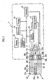
- Fig. 1 shows a sample analyzer 1 which measures a specific component in a sample, using a biosensor 2 attached thereto. inlet 25a and the hole 23.
- the biosensor 2 is able to supply a sample via the sample inlet 25a to the capillary 25, and the sample supplied from the sample inlet 25a is able to move by capillarity toward the hole 23 in the capillary 25.
- the first surface 20a of the substrate 20 is provided with measuring electrodes 26, 27, detection electrodes 28, 29, and a reagent region 30.
- the reagent region 30 is a porous solid for example, easily soluble in water, and interconnects ends 26a, 27a, 28a, 29a of the electrodes 26-29.
- the reagent region 30 includes e.g. an oxidation-reduction enzyme and an electron transfer material in the form of oxide.
- the reagent region 30 constructed as the above is dissolved by the sample as the sample is introduced from the sample inlet 25a and moves through the capillary 25. This establishes a liquid reaction field which makes contact with all of the electrodes 26-29, in the capillary 25.
- a specific component in e. g. the sample is oxidized and the electron transfer material is reduced.
- the electron transfer material releases electrons, to become an oxide, and the amount of released electrons can be measured as a response current, by using the electrodes 26-29.
- the sample analyzer 1 in Fig. 1 includes a terminal regions 10a-10d, a first through a fourth switches 11a-11d, a voltage applier 12, an electric current measurer 13, a detector 14, a controller 15, a storage 16, an arithmetic operator 17, and a display 18.
- the terminal regions 10a-10d make contact with ends 26b-29b of the electrodes 26-29 when the biosensor 2 is attached to the sample analyzer 1.
- the voltage applier 12 which applies a voltage to the liquid reaction field, is provided by a DC power source such as an ordinary dry battery or a rechargeable battery.
- the electric current value measurer 13 measures a response current when the voltage is applied to the liquid reaction field.
- the first through the fourth switches 11a-11d select the state of terminal regions 10a-10d, i.e. whether ornot they are connected with the voltage applier 12 and the electric current measurer 13.
- Each of the switches 11a-11d is turned on and off individually by the controller 15. Therefore, by selecting the ON or OFF state for each of the switches 11a-11d, it is possible to select a combination of electrodes from the electrodes 26-29, for application of a voltage to the liquid reaction field.
- the detector 14 detects whether ornot it is possible to perform an analysis by using the biosensor 2. Specifically, the detector 14 detects whether or not the biosensor 2 has been attached to the sample analyzer 1, whether or not the sample has been introduced into the capillary 25, whether or not the capillary 25 has been filled with the sample, and whether or not the sample has been moved after the sample is introduced into the capillary 25.
- the controller 15 controls the switches 11a-11d as described above, as well as the detector 14, the arithmetic operator 17 and so on.
- the storage 16 stores a variety of programs, calibration curve data and other data necessary for running the programs.
- the calibration curve data indicates a relationship between measured response current values (or voltage values obtained by converting the response current values, or accumulated quantity of electric charge obtained from the response current values) and the concentration of the specific component.
- the arithmetic operator 17 calculates the concentration of the specific component in the sample, based on the response current measured by the electric current measurer 13.
- the display 18 displays results of the calculation made by the arithmetic operator 17, error messages and so on.
- the display 18 is provided by a liquid crystal display device for example.
- each of the detector 14, the controller 15, the storage 16 and the arithmetic operator 17 can be provided by e.g. a CPU, a ROM, a RAM or combination thereof.
- description will cover how the biosensor 2 and the sample analyzer 1 may be used in an analyzing procedure.
- the description will take an amperometric method for a measurement of blood glucose level, with reference to Fig. 1 , Fig. 4 and Fig. 5 . Note that all of the first through the fourth switches 11a-11d are turned OFF before the analysis begins.
- a sensor such as an optical sensor or a pressure sensor, and the detector 14 makes the determination based on an output from the sensor.
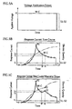
- the controller 15 turns on the first and the second switches 11a, 11d (S2). Under this state, a constant voltage v is applied between the measuring electrodes 26, 27 by the voltage applier 12 (See the solid line (W-C) in Fig. 5A ).
- the detector 14 determines if the blood has been introduced into the capillary 25 (S3).
- the determination whether or not the blood has been introduced is made by checking whether or not a response current measured via the measuring electrodes 26, 27 has exceeded a predetermined threshold value I, (See Fig. 5B ).
- the detection of the blood introduction into the capillary 25 is made by detecting electric conduction between the measuring electrodes 26, 27, i.e. by detecting whether or not the blood has reached a region where the electrodes 26, 27 are.
- Step S3 is repeated until the introduction of blood has been detected. However, if Step S3 has been repeated for a predetermined number of times, or if the blood introduction is not detected within a predetermined duration of time, then the determination at Step S3 may be stopped and the program may go to an error processing routine.
- the electric current measurer 13 measures a response current at a predetermined time interval (S4).
- the blood which is introduced dissolves the reagent region 30, and a liquid reaction field is formed in the capillary 25 which includes the oxidation-reduction enzyme, the electron transfer material and glucose.
- a liquid reaction field is formed in the capillary 25 which includes the oxidation-reduction enzyme, the electron transfer material and glucose.
- electrons are taken out of the glucose for example, and these electrons are supplied to the electron transfer material, causing the electron transfer material to become a reductant.
- the liquid reaction field is applied with a voltage which results from an electric potential difference between the measuring electrodes 26, 27.
- the reductant releases electrons to the measuring electrode 26, and becomes an oxidant again.
- a response current measured at the electric current measurer 13 is correlated with the amount of electrons released by the reductant, i. e. the amount of electrons taken out of the glucose, and thus the electric current reflects the glucose concentration.
- Step S5 determines that the predetermined amount of time has not been passed (S5: NO)
- the electric current measurer 13 repeats the measurement of a response current (S4) until the arithmetic operator 17 determines that the predetermined amount of time has passed (S5: YES).
- the time interval for the response current measurement is 0.02-0.2 sec. for example, and the measured response current values are stored in the storage 16, together with e.g. the time of measurement.
- the detector 14 determines if there has been a movement of blood in the capillary 25 (S7).
- the determination whether or not the blood has moved is made, for example, by checking a response current time course shown in Fig. 5B and Fig. 5C to see if the first peak P1 is followed by the second peak P2. If there is no blood movement, the response current decreases straightly with time, after reaching the first peak P1 as shown in Fig. 5B .
- glucose concentration distribution changes in the capillary 25, and the glucose concentration increases around the end 26a of the measuring electrode 26. For this reason, if there is a blood movement, the response current increases upon the blood movement, resulting in the second peak P2 as shown in Fig. 5C . Therefore, by checking whether or not the second peak P2 appears, it is possible to determine if the blood has moved or not.
- the blood movement phenomenon appears when, e.g. there has been an additional supply of blood to the capillary 25 after a blood introduction is detected in Step S3 (S3: YES), or when blood which has once stopped in movement resumes its movement spontaneously or due to application of external force such as vibration.
- Detection of the second peak P2 is made by e.g. comparing a response current I 2 at each point of measurement A with a response current I 3 at a comparative point of measurement B which is a point right before the given point of measurement A. More specifically, if a response current I 2 at a point of measurement A is greater than a response current I 3 by a predetermined value, it is determined that the second peak P2 has appeared. With this arrangement, the detector 14 determines that there has been a blood movement in the capillary 25 if the second peak P2 has appeared (See Fig. 5C ), while determining that there has not been a blood movement if the second peak has not appeared (See Fig. 5B ).
- a response current at a point of measurement A can be greater than a response current at the comparative measuring point B due to noise or measurement errors, even if there has not been a blood movement. Such a phenomenon appears more significantly when measurements are made in a small time interval. If this poses a problem, the above-described predetermined value is set to include the influence by noise and measurement errors.
- the detector 14 determines that there has been a blood movement (S7: YES), the detector 14 recognizes that there has been an error in measurement due to the blood movement (S8).
- the detector 14 determines that there has been no blood movement (S7: NO), or recognizes in Step S8 that there has been an error, the detector 14 checks if the capillary 25 has been supplied with a target amount of the blood (S9).
- Whether or not the target amount of blood has been supplied is determined by checking if the capillary 25 is filled with the sample. This determination is made by checking if a response current measured via the detection electrodes 28, 29 exceeds the threshold value I 1 (See Fig. 5B ). If the response current measured via the detection electrodes 28, 29 exceeds the threshold value I 1 (See Fig. 5B ), it is assumable that the blood has reached at least a region around the detection electrodes 28, 29, so the capillary 25 has been filled with the blood. Thus, measurement of the response current using the detection electrodes 28, 29 enables to determine if the capillary 25 has been supplied with the target amount of blood.
- Step S9 the measurement of a response current for the determination may be made only once in a predetermined period of time after the beginning of the voltage application in Step S6, or may be repeated for a predetermined period of time.
- the detector 14 determines that the capillary 25 has not been filled with the target amount of blood (S9: NO), the detector 14 recognizes that this is an error due to insufficient blood supply (S10).
- the arithmetic operator 17 calculates glucose concentration based on a response current upon the lapse of the predetermined period of time (S11). The calculation of the glucose concentration is made on the basis of e.g. a predetermined calibration curve or lookup table which relates the response current to the glucose concentration.
- a result of the calculation (blood sugar level) given by the arithmetic operator 17 is displayed on the display 18 (S12).
- the detector 14 recognizes an error (S8, S10) (S13: YES)
- an error message is displayed on the display 18 (S14).
- the error message may simply be that the measurement was not successful, or may include more detailed information (e.g. blood movement or insufficient supply of blood).
- the sample analyzer 1 ceases the concentration measuring operation if Step S1 finds that no biosensor 2 is attached (S1: NO), if the detector 14 recognizes no error (S8, S10) in Step S13 (S13: NO), or if an error message is displayed (S14).
- Steps S7 and S9 may be swapped with each other.
- a voltage application for obtaining a response current which is necessary for calculating blood glucose level is made first, and thereafter, a voltage application for obtaining a response current which is necessary for detecting if a target amount of blood has been supplied.
- no voltage application is made for obtaining a response current necessary for the detection, during the time when a response current for the calculation is being obtained. Therefore, during the voltage application for detecting blood supply, no consumption is made on the reductant of electron transfer material which reflects the glucose concentration and thus must be retained until a response current for calculation has been obtained.
- no disturbance is made to a uniform concentration of the reductant of electron transfer material when obtaining a response current for calculation. As a result, measuring accuracy is not decreased by the detection of blood supply.
- the detector 14 recognizes an error (S8, S10), blood sugar level is calculated (S11) and the calculation result is displayed (S12). Therefore, as compared with a case in which the measuring operation is simply ceased upon an error, the user can anyway obtain a result of measurement even if there has been an error during the measuring operation and the measurement result can only be useful as a reference data. As a result, it becomes possible to reduce meaningless use of the biosensors. Further, displaying an error message (S14) enables to make clear that the measuring result on the display 18 is a reference data, and further, displaying a detailed error message enables for the user to learn from the failure and not repeat the same mistake.
- the present invention is not limited to the form of embodiment thus far described.
- the electrodes formed in the biosensor 2 maybe three, i. e. one detection electrode, one working electrode and one counter electrode. In this case, detection of sample supply will be made by using the detection electrode and the working electrode (or the counter electrode) .
- a voltage application in order to obtain a response current for detecting sample introduction and a voltage application to obtain a response current for calculation may not necessarily be made continuously.
- the voltage application may be stopped upon detection of sample introduction, and then resumed in a predetermined period of time in order to obtain a response current for calculation.
- the present embodiment uses an amperometric technique in the measurement of blood glucose level, and the description was made accordingly.
- the present invention is also applicable to measurement of blood glucose level using a coulometric technique.
- measurement of response current is made for e.g. a predetermined period of time upon detection of blood introduction after a voltage application, and the blood glucose level is calculated from the electric quantity obtained by accumulating these response currents.
- additional application of voltage is made in order to obtain a response current for detecting if the sample has been introduced appropriately.
- whether the blood has moved or not is determined by checking the time course of electric quantity, to see if an inflexion point appears or not.
Abstract
Description
- The present invention relates to a technique for analyzing samples.
- As a common method for analyzing samples, an oxidation-reduction reaction is used. An example is a quantitative procedure disclosed in
JP-A 2001-330581 - As will be expected from
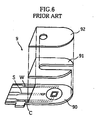
Fig. 6 of the present application, the biosensor disclosed in the gazette makes use of a capillary which is formed by laminating acover 92 onto asubstrate 90 via aspacer 91, for measurement of blood sugar level. Thesubstrate 90 has a surface formed with a working electrode W, a counter electrode C and a liquid junction sensing electrode S. Though not illustrated in the figure, a reagent region is provided so as to bridge at least an end of the working electrode w with an end of the counter electrode C. The reagent region includes an oxidation-reduction enzyme and an electron transfer material. - In this
biosensor 9, when blood is introduced into the capillary, a liquid reaction field is formed which includes the oxidation-reduction enzyme, the electron transfer material and glucose, in the capillary. In the liquid reaction field, electron transfer takes place between glucose and the electron transfer material. The electron transfer material becomes a reductant (or an oxidant). Then, when a voltage is applied to the liquid reaction field via the working electrode W and the counter electrode C, electron transfer takes place between the working electrode W and the reductant (oxidant), which generates a response current necessary for analyzing the sample. On the other hand, by applying a voltage to the liquid reaction field via the liquid junction sensing electrode S and the working electrode W (or the counter electrode C), it is possible to obtain a response current necessary for detecting whether or not the capillary has been filled with the sample. The voltage application via the liquid junction sensing electrode S and the working electrode W (or the counter electrode C) ceases if the response current for detection exceeds a predetermined value. Specifically, if a liquid junction is detected between the liquid junction sensing electrode S and the working electrode W (or the counter electrode C), blood has already reached the liquid junction sensing electrode S. So, detection of a liquid junction justifies an assumption that the capillary has been filled with the sample. - However, according to the quantitative procedure described above, the response current for detection is obtained simultaneously with the obtainment of the response current for analysis. In other words, a voltage is applied to the liquid reaction field simultaneously, for a different purpose than obtaining a response current for analysis, using the liquid junction sensing electrode S. During this process, part of glucose which is supposed to be used for the measurement of response current for analysis is used for the detection of sample supply. Further, this causes non-uniformity in the concentration of glucose or reductant (oxidant) in there action field. As a result, the response current for analysis does not necessarily reflect the glucose concentration appropriately. Further, severity of non-uniformity is not always the same, which leads to a problem of decreased measuring accuracy.
- An object of the present invention is to make possible to detect whether or not a target amount of sample has been supplied to the reaction field, without sacrificing accuracy of the analysis.
- According to a first aspect the invention provides a sample analyzing method based on a response obtained upon application of a voltage to a reaction field containing a sample, comprising:
- a first step for measuring a first response for use in calculation necessary for analyzing the sample, and
- a second step performed later than the first step for measuring a second response necessary to determine whether a target amount of the sample has been supplied to the reaction field;
- wherein the application of voltage to the reaction field in the first and the second steps is made by using two electrodes selected from three or more electrodes, and a combination of two electrodes selected in the first step differs from a combination of two electrodes selected in the second step,
- wherein use is made of an analyzing tool which includes a substrate provided with a capillary for moving the sample, the substrate being also provided with said three or more electrodes, each of the electrodes having a respective part lined up in the capillary in a direction of the sample movement, and
- wherein at least one of the two electrodes selected for measurement of the second response in the second step has its part disposed downstream of the sample flow from the two electrodes selected in the first step.
- Preferably, in the first and the second steps, the first and the second responses are measured as electric currents. The first and the second responses may of course be measured in the form of voltage, electric capacitance, quantity of light, and so on.
- Preferably, the sample analyzing method according to the present invention further includes a third step of determining whether or not the sample has moved in the reaction field while carrying out the first step.
- Preferably, in the first step, the first response is measured at a plurality of measuring points at every predetermined time interval. With this, the determination in the third step on whether or not the sample has moved in the reaction field is made by checking a time course of the responses obtained from the measuring points to see whether or not a first peak which appears first is followed by a second peak
- Preferably, if the first response is measured as a response current at each of the measuring points, the determination in e.g. the third step on whether or not the second peak has appeared is made as follows. Specifically, a response current measured at one of the measuring points is compared with a response current measured at another of the measuring points located right before that one measuring point in the time course, to see if the response current at that one measuring point exceeds the response current at that another measuring point by a predetermined or greater value.
- Alternatively, in the third step, the determination on whether or not the sample has moved in the reaction field may be made by checking a time course of accumulated response values obtained from each measuring point to see whether or not there has appeared an inflexion point.
- In a preferred embodiment, there is provided a sample analyzing method based on a response obtained upon application of a voltage to a reaction field containing the sample. The method includes a step of measuring a response at a plurality of measuring points at every specific time interval for use in calculation necessary for analyzing the sample, and an additional step of determining whether or hot the sample has moved in the reaction field. The determination in the additional step on whether or not the sample has moved in the reaction field is made by checking a time course of the responses obtained from the measuring points to see whether or not a first peak which appears first is followed by a second peak.
- The response is measured e.g. as a response current at each of the measuring points. In this case, the determination in the additional step on whether or not the second peak has appeared is made as follows. Specifically, a response current measured at one of the measuring points is compared with a response current measured at another of the measuring points located right before that one measuring point in the time course, to see if the response current at that one measuring point exceeds the response current at that another measuring point by a predetermined or greater value.
- In a preferred embodiment, there is provided a sample analyzing method of analyzing a sample based on a response obtained upon application of a voltage to a reaction field containing the sample. The method includes a step of measuring a response at a plurality of measuring points at every specific time interval for use in calculation necessary for analyzing the sample, and an additional step of determining whether or not the sample has moved in the reaction field. The determination in the additional step on whether or not the sample has moved in the reaction field is made by checking a time course of accumulated response values obtained from each measuring point to see whether or not there has appeared an inflexion point.
- According to a second aspect, the invention provides a sample analyzing system including a sample analyzer and an analyzing tool adapted to be attached to the sample analyzer,
wherein the sample analyzer comprises: - a voltage applier for application of a voltage to a reaction field including a sample;
- a response measurer for measurement of a response to the voltage applied to the reaction field;
- a selector for selecting a first voltage application state for measurement of a first response for use in calculation necessary for analyzing the sample, or a second voltage application state for measurement of a second response for use in determining whether or not the reaction field has been supplied with a target amount of the sample;
- an arithmetic operator for calculation necessary for analyzing the sample based on the first response;
- a determiner for determination based on the second response, on whether or not the reaction field has been supplied with the target amount of sample; and
- a controller for causing the selector to select the second voltage application state after causing the selector (11a-11d) to select the first voltage application state;
- wherein the analyzing tool comprises three or more electrodes for applying voltage to the reaction field,
- wherein the voltage applier applies the voltage to the reaction field via two electrodes selected from the three or more electrodes, and a combination of two electrodes selected for measurement of the first response differs from a combination of two electrodes selected for measurement of the second response, and
- wherein the analyzing tool includes a substrate on which the three or more electrodes are provided, and a capillary for moving the sample, part of each electrode being lined up in the capillary in a direction of the sample movement,
- the controller controlling the selector in selecting the two electrodes for measurement of the second response, to include at least one electrode having its part disposed downstream of the sample flow from the two electrodes selected for measurement of the first response. Preferably, the measurer measures e.g. the first and the second responses as electric currents in the first and the second steps.
- Preferably, the selector includes e.g. a switch for individual selection for the three or more electrodes, of a state in which the electrode is electrically connected with the voltage applier or a state in which it is not.
- The sample analyzer preferably further includes an additional determiner for determining whether or not the sample has moved in the reaction field while measuring the first response. In this case, it is preferable that the arithmetic operator recognizes an error if the determiner determines that there has not been a supply of a target amount of the sample, or if the additional determiner determines that there has been a movement of the sample, and yet, the arithmetic operator makes calculation necessary for analyzing the sample regardless of the error.
- The sample analyzer according to the present invention may further include a display for displaying a result of calculation made by the arithmetic operator and an error message. In this case, preferably, the display displays a content of the error upon recognition of the error by the arithmetic operator.
- It should be noted here that the "movement of the sample in the reaction field" includes a case where there has been an additional supply of the sample to the reaction field, and a case where the sample which has once moved and stopped moves again spontaneously or due to external force.
-
-
Fig. 1 shows a sample analyzer according to the present invention, mounted with a biosensor. The sample analyzer is shown in a block diagram whereas the biosensor is shown in a plan view. -
Fig. 2 is an overall perspective view of the biosensor inFig. 1 . -
Fig. 3 is an exploded perspective view of the biosensor inFig. 2 . -
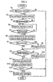
Fig. 4 is a flowchart for describing an operation in the sample analyzer. -
Fig. 5A is a graph showing a voltage application pattern in a sample analysis;Fig. 5B is a graph showing time courses of a response current and an accumulated quantity of electric charge with respect to the voltage application pattern inFig. 5A; and Fig. 5C is a graph showing time courses of a response current and an accumulated quantity of electric charge when there was an additional supply of sample. -
Fig. 6 is an exploded perspective view of a conventional biosensor. - A preferred embodiment of the present invention will now be described, by way of example only, and with reference to the drawings.
-
Fig. 1 shows a sample analyzer 1 which measures a specific component in a sample, using abiosensor 2 attached thereto.inlet 25a and thehole 23. In other words, thebiosensor 2 is able to supply a sample via thesample inlet 25a to the capillary 25, and the sample supplied from thesample inlet 25a is able to move by capillarity toward thehole 23 in the capillary 25. - The
first surface 20a of thesubstrate 20 is provided with measuringelectrodes detection electrodes reagent region 30. Thereagent region 30 is a porous solid for example, easily soluble in water, and interconnects ends 26a, 27a, 28a, 29a of the electrodes 26-29. Thereagent region 30 includes e.g. an oxidation-reduction enzyme and an electron transfer material in the form of oxide. - The
reagent region 30 constructed as the above is dissolved by the sample as the sample is introduced from thesample inlet 25a and moves through the capillary 25. This establishes a liquid reaction field which makes contact with all of the electrodes 26-29, in the capillary 25. In this liquid reaction field, due to catalytic activity by the oxidation-reduction enzyme, a specific component in e. g. the sample is oxidized and the electron transfer material is reduced. When a voltage is applied to the liquid reaction field via the electrodes 26-29, the electron transfer material releases electrons, to become an oxide, and the amount of released electrons can be measured as a response current, by using the electrodes 26-29. - The sample analyzer 1 in
Fig. 1 includes aterminal regions 10a-10d, a first through afourth switches 11a-11d, avoltage applier 12, an electriccurrent measurer 13, adetector 14, acontroller 15, astorage 16, anarithmetic operator 17, and adisplay 18. - The
terminal regions 10a-10d make contact with ends 26b-29b of the electrodes 26-29 when thebiosensor 2 is attached to the sample analyzer 1. - The
voltage applier 12, which applies a voltage to the liquid reaction field, is provided by a DC power source such as an ordinary dry battery or a rechargeable battery. - The electric
current value measurer 13 measures a response current when the voltage is applied to the liquid reaction field. - The first through the
fourth switches 11a-11d select the state ofterminal regions 10a-10d, i.e. whether ornot they are connected with thevoltage applier 12 and the electriccurrent measurer 13. Each of theswitches 11a-11d is turned on and off individually by thecontroller 15. Therefore, by selecting the ON or OFF state for each of theswitches 11a-11d, it is possible to select a combination of electrodes from the electrodes 26-29, for application of a voltage to the liquid reaction field. - The
detector 14 detects whether ornot it is possible to perform an analysis by using thebiosensor 2. Specifically, thedetector 14 detects whether or not thebiosensor 2 has been attached to the sample analyzer 1, whether or not the sample has been introduced into the capillary 25, whether or not the capillary 25 has been filled with the sample, and whether or not the sample has been moved after the sample is introduced into the capillary 25. - The
controller 15 controls theswitches 11a-11d as described above, as well as thedetector 14, thearithmetic operator 17 and so on. - The
storage 16 stores a variety of programs, calibration curve data and other data necessary for running the programs. The calibration curve data indicates a relationship between measured response current values (or voltage values obtained by converting the response current values, or accumulated quantity of electric charge obtained from the response current values) and the concentration of the specific component. - The
arithmetic operator 17 calculates the concentration of the specific component in the sample, based on the response current measured by the electriccurrent measurer 13. - The
display 18 displays results of the calculation made by thearithmetic operator 17, error messages and so on. Thedisplay 18 is provided by a liquid crystal display device for example. - It should be noted here that each of the
detector 14, thecontroller 15, thestorage 16 and thearithmetic operator 17 can be provided by e.g. a CPU, a ROM, a RAM or combination thereof. - Hereinafter, description will cover how the
biosensor 2 and the sample analyzer 1 may be used in an analyzing procedure. As an example, the description will take an amperometric method for a measurement of blood glucose level, with reference toFig. 1 ,Fig. 4 andFig. 5 . Note that all of the first through thefourth switches 11a-11d are turned OFF before the analysis begins. - In the sample analyzer 1, first, a determination is made if the
biosensor 2 is attached or not (S1). In the determination process, use is made of a sensor such as an optical sensor or a pressure sensor, and thedetector 14 makes the determination based on an output from the sensor. - When the
detector 14 determines that thebiosensor 2 is attached to the sample analyzer 1 (S1.: YES), thecontroller 15 turns on the first and thesecond switches 11a, 11d (S2). Under this state, a constant voltage v is applied between the measuringelectrodes Fig. 5A ). - Then, the
detector 14 determines if the blood has been introduced into the capillary 25 (S3). The determination whether or not the blood has been introduced is made by checking whether or not a response current measured via the measuringelectrodes Fig. 5B ). In other words, the detection of the blood introduction into the capillary 25 is made by detecting electric conduction between the measuringelectrodes electrodes - If the
detector 14 determines that the blood has not been introduced into the capillary 25 (S3: NO), Step S3 is repeated until the introduction of blood has been detected. However, if Step S3 has been repeated for a predetermined number of times, or if the blood introduction is not detected within a predetermined duration of time, then the determination at Step S3 may be stopped and the program may go to an error processing routine. - On the contrary, if the
detector 14 determines that the blood has been introduced into the capillary 25 (S3: YES), the electriccurrent measurer 13 measures a response current at a predetermined time interval (S4). - In the capillary 25, the blood which is introduced dissolves the
reagent region 30, and a liquid reaction field is formed in the capillary 25 which includes the oxidation-reduction enzyme, the electron transfer material and glucose. In this liquid reaction field, electrons are taken out of the glucose for example, and these electrons are supplied to the electron transfer material, causing the electron transfer material to become a reductant. - On the other hand, the liquid reaction field is applied with a voltage which results from an electric potential difference between the measuring
electrodes electrode 26, and becomes an oxidant again. In such an electron transfer, a response current measured at the electriccurrent measurer 13 is correlated with the amount of electrons released by the reductant, i. e. the amount of electrons taken out of the glucose, and thus the electric current reflects the glucose concentration. - If a response current has been measured (S4), the
arithmetic operator 17 checks (S5) if a predetermined amount of time has been lapsed since the detection of the blood introduction (S3: YES). If Step S5 determines that the predetermined amount of time has not been passed (S5: NO), the electriccurrent measurer 13 repeats the measurement of a response current (S4) until thearithmetic operator 17 determines that the predetermined amount of time has passed (S5: YES). - The time interval for the response current measurement is 0.02-0.2 sec. for example, and the measured response current values are stored in the
storage 16, together with e.g. the time of measurement. - When the
arithmetic operator 17 determines that the predetermined amount of time has passed (S5: YES), the first and thesecond switches 11a, 11d are turned off whereas the third and thefourth switches detection electrodes Fig. 5A ) - On the other hand, the
detector 14 determines if there has been a movement of blood in the capillary 25 (S7). The determination whether or not the blood has moved is made, for example, by checking a response current time course shown inFig. 5B and Fig. 5C to see if the first peak P1 is followed by the second peak P2. If there is no blood movement, the response current decreases straightly with time, after reaching the first peak P1 as shown inFig. 5B . On the contrary, if there is a blood movement, glucose concentration distribution changes in the capillary 25, and the glucose concentration increases around theend 26a of the measuringelectrode 26. For this reason, if there is a blood movement, the response current increases upon the blood movement, resulting in the second peak P2 as shown inFig. 5C . Therefore, by checking whether or not the second peak P2 appears, it is possible to determine if the blood has moved or not. - The blood movement phenomenon appears when, e.g. there has been an additional supply of blood to the capillary 25 after a blood introduction is detected in Step S3 (S3: YES), or when blood which has once stopped in movement resumes its movement spontaneously or due to application of external force such as vibration.
- Detection of the second peak P2 is made by e.g. comparing a response current I2 at each point of measurement A with a response current I3 at a comparative point of measurement B which is a point right before the given point of measurement A. More specifically, if a response current I2 at a point of measurement A is greater than a response current I3 by a predetermined value, it is determined that the second peak P2 has appeared. With this arrangement, the
detector 14 determines that there has been a blood movement in the capillary 25 if the second peak P2 has appeared (SeeFig. 5C ), while determining that there has not been a blood movement if the second peak has not appeared (SeeFig. 5B ). - It should be noted here that a response current at a point of measurement A can be greater than a response current at the comparative measuring point B due to noise or measurement errors, even if there has not been a blood movement. Such a phenomenon appears more significantly when measurements are made in a small time interval. If this poses a problem, the above-described predetermined value is set to include the influence by noise and measurement errors.
- If the
detector 14 determines that there has been a blood movement (S7: YES), thedetector 14 recognizes that there has been an error in measurement due to the blood movement (S8). - If the
detector 14 determines that there has been no blood movement (S7: NO), or recognizes in Step S8 that there has been an error, thedetector 14 checks if the capillary 25 has been supplied with a target amount of the blood (S9). - Whether or not the target amount of blood has been supplied is determined by checking if the capillary 25 is filled with the sample. This determination is made by checking if a response current measured via the
detection electrodes Fig. 5B ). If the response current measured via thedetection electrodes Fig. 5B ), it is assumable that the blood has reached at least a region around thedetection electrodes detection electrodes - In Step S9, the measurement of a response current for the determination may be made only once in a predetermined period of time after the beginning of the voltage application in Step S6, or may be repeated for a predetermined period of time.
- If the
detector 14 determines that the capillary 25 has not been filled with the target amount of blood (S9: NO), thedetector 14 recognizes that this is an error due to insufficient blood supply (S10). - If the
detector 14 determines that the capillary 25 has been filled with the target amount of blood (S9: YES), or thedetector 14 recognizes that there has been an error in Step S10, thearithmetic operator 17 calculates glucose concentration based on a response current upon the lapse of the predetermined period of time (S11). The calculation of the glucose concentration is made on the basis of e.g. a predetermined calibration curve or lookup table which relates the response current to the glucose concentration. - A result of the calculation (blood sugar level) given by the
arithmetic operator 17 is displayed on the display 18 (S12). On the other hand, if thedetector 14 recognizes an error (S8, S10) (S13: YES), an error message is displayed on the display 18 (S14). The error message may simply be that the measurement was not successful, or may include more detailed information (e.g. blood movement or insufficient supply of blood). - The sample analyzer 1 ceases the concentration measuring operation if Step S1 finds that no
biosensor 2 is attached (S1: NO), if thedetector 14 recognizes no error (S8, S10) in Step S13 (S13: NO), or if an error message is displayed (S14). - It should be noted here that the determination if the blood has been moved (S7) and the determination if the target amount of blood has been supplied (S9) may be made after the calculation of the glucose concentration (S11). Further, Steps S7 and S9 may be swapped with each other.
- According to the present embodiment, a voltage application for obtaining a response current which is necessary for calculating blood glucose level is made first, and thereafter, a voltage application for obtaining a response current which is necessary for detecting if a target amount of blood has been supplied. In other words, no voltage application is made for obtaining a response current necessary for the detection, during the time when a response current for the calculation is being obtained. Therefore, during the voltage application for detecting blood supply, no consumption is made on the reductant of electron transfer material which reflects the glucose concentration and thus must be retained until a response current for calculation has been obtained. Likewise, no disturbance is made to a uniform concentration of the reductant of electron transfer material when obtaining a response current for calculation. As a result, measuring accuracy is not decreased by the detection of blood supply.
- According to the present embodiment, further, even when the
detector 14 recognizes an error (S8, S10), blood sugar level is calculated (S11) and the calculation result is displayed (S12). Therefore, as compared with a case in which the measuring operation is simply ceased upon an error, the user can anyway obtain a result of measurement even if there has been an error during the measuring operation and the measurement result can only be useful as a reference data. As a result, it becomes possible to reduce meaningless use of the biosensors. Further, displaying an error message (S14) enables to make clear that the measuring result on thedisplay 18 is a reference data, and further, displaying a detailed error message enables for the user to learn from the failure and not repeat the same mistake. - Obviously, the present invention is not limited to the form of embodiment thus far described. For example, the electrodes formed in the
biosensor 2 maybe three, i. e. one detection electrode, one working electrode and one counter electrode. In this case, detection of sample supply will be made by using the detection electrode and the working electrode (or the counter electrode) . - A voltage application in order to obtain a response current for detecting sample introduction and a voltage application to obtain a response current for calculation may not necessarily be made continuously. In other words, the voltage application may be stopped upon detection of sample introduction, and then resumed in a predetermined period of time in order to obtain a response current for calculation.
- The present embodiment uses an amperometric technique in the measurement of blood glucose level, and the description was made accordingly. However, the present invention is also applicable to measurement of blood glucose level using a coulometric technique. When using a coulometric technique, measurement of response current is made for e.g. a predetermined period of time upon detection of blood introduction after a voltage application, and the blood glucose level is calculated from the electric quantity obtained by accumulating these response currents. After the obtainment of the response current values for calculation, additional application of voltage is made in order to obtain a response current for detecting if the sample has been introduced appropriately. On the other hand, whether the blood has moved or not is determined by checking the time course of electric quantity, to see if an inflexion point appears or not. Specifically, as shown in a long-dashed-double-short-dashed line in
Fig. 5B , the electric quantity increases straightly with time if there is no blood movement. On the other hand, as shown in a long-dashed-double-short-dashed line inFig. 5C , an inflexion point Q appears in the time graph of electric quantity if there is a blood movement. Therefore, it is possible to detect a blood movement by checking if there appears an inflexion point Q.
Claims (11)
- A sample analyzing method based on a response obtained upon application of a voltage to a reaction field containing a sample, comprising:a first step for measuring a first response for use in calculation necessary for analyzing the sample; anda second step performed later than the first step for measuring a second response necessary to determine whether a target amount of the sample has been supplied to the reaction field;wherein the application of voltage to the reaction field in the first and the second steps is made by using two electrodes selected from three or more electrodes (26-29), and a combination of two electrodes selected in the first step differs from a combination of two electrodes selected in the second step,wherein use is made of an analyzing tool (2) which includes a substrate (20) provided with a capillary (25) for moving the sample, the substrate (20) being also provided with said three or more electrodes (26-29), each of the electrodes (26-29) having a respective part lined up in the capillary (25) in a direction of the sample movement, andwherein at least one of the two electrodes selected for measurement of the second response in the second step has its part disposed downstream of the sample flow from the two electrodes selected in the first step.
- The sample analyzing method according to claim 1, wherein the first and the second responses are measured as electric currents in the first and the second steps.
- The sample analyzing method according to claim 1, further comprising a third step for determining whether or not the sample has moved in the reaction field while carrying out the first step, wherein the first response is measured at a plurality of measuring points at every predetermined time interval in the first step, and the determination in the third step on whether or not the sample has moved in the reaction field is made by checking a time course of the responses obtained from the measuring points to see whether or not a first peak which appears first is followed by a second peak.
- The sample analyzing method according to claim 3, wherein the first response is measured as a response current at each of the measuring points in the first step,
the determination in the third step on whether or not the second peak has appeared being made by comparing a response current measured at one of the measuring points with a response current measured at another of the measuring points located right before said one measuring point in the time course, and by checking if the response current at said one measuring point exceeds the response current at said another measuring point by a predetermined or greater value. - The sample analyzing method according to claim 3, wherein the first response is measured at a plurality of measuring points at every predetermined time interval in the first step,
the determination in the third step on whether or not the sample has moved in the reaction field being made by checking a time course of accumulated response values obtained from each measuring point to see whether or not there has appeared an inflexion point. - A sample analyzing system (1, 2) including a sample analyzer (1) and an analyzing tool (2) adapted to be attached to the sample analyzer (1),
wherein the sample analyzer (1) comprises:a voltage applier (12) for application of a voltage to a reaction field including a sample;a response measurer (13) for measurement of a response to the voltage applied to the reaction field;a selector (11a-11d) for selecting a first voltage application state for measurement of a first response for use in calculation necessary for analyzing the sample, or a second voltage application state for measurement of a second response for use in determining whether or not the reaction field has been supplied with a target amount of the sample;an arithmetic operator (17) for calculation necessary for analyzing the sample based on the first response;a determiner (14) for determination based on the second response, on whether or not the reaction field has been supplied with the target amount of sample; anda controller (15) for causing the selector (11a-11d) to select the second voltage application state after causing the selector (11a-11d) to select the first voltage application state;wherein the analyzing tool (2) comprises three or more electrodes (26-29) for applying voltage to the reaction field,wherein the voltage applier (12) applies the voltage to the reaction field via two electrodes selected from the three or more electrodes (26-29), and a combination of two electrodes selected for measurement of the first response differs from a combination of two electrodes selected for measurement of the second response, andwherein the analyzing tool (2) includes a substrate (20) on which the three or more electrodes (26-29) are provided, and a capillary (25) for moving the sample, part of each electrode being lined up in the capillary (25) in a direction of the sample movement, the controller (15) controlling the selector (11a-11d) in selecting the two electrodes for measurement of the second response, to include at least one electrode having its part disposed downstream of the sample flow from the two electrodes selected for measurement of the first response. - The sample analyzing system (1,2) according to claim 6, wherein the measurer (13) measures the first and the second responses as electric currents in the first and the second steps.
- The sample analyzing system (1, 2) according to claim 6, wherein the selector (11a-11d) includes a switch for individual selection for the three or more electrodes (26-29), of a state in which the electrode is electrically connected with the voltage applier (12) or a state in which it is not.
- The sample analyzing system (1, 2) according to claim 6, further comprising an additional determiner (14) for determining whether or not the sample has moved in the reaction field while measuring the first response,
the arithmetic operator (17) recognizing an error upon determination by the determiner (14) of not receiving a supply of a target amount of the sample or upon determination by the additional determiner (14) of a movement of the sample, the arithmetic operator (17) making calculation necessary for analyzing the sample regardless of the error. - The sample analyzing system (1, 2) according to claim 9, further comprising a display (18) for displaying a result of calculation made by the arithmetic operator (17) and an error message.
- The sample analyzing system (1, 2) according to claim 10, wherein the display (18) displays a content of the error upon recognition of the error by the arithmetic operator.
Priority Applications (1)
| Application Number | Priority Date | Filing Date | Title |
|---|---|---|---|
| EP09013026.1A EP2149792B1 (en) | 2002-07-25 | 2003-07-23 | Sample analyzing method |
Applications Claiming Priority (3)
| Application Number | Priority Date | Filing Date | Title |
|---|---|---|---|
| JP2002216314 | 2002-07-25 | ||
| JP2002216314 | 2002-07-25 | ||
| PCT/JP2003/009357 WO2004011921A1 (en) | 2002-07-25 | 2003-07-23 | Sample analyzing method and sample analyzing device |
Related Child Applications (2)
| Application Number | Title | Priority Date | Filing Date |
|---|---|---|---|
| EP09013026.1A Division EP2149792B1 (en) | 2002-07-25 | 2003-07-23 | Sample analyzing method |
| EP09013026.1 Division-Into | 2009-10-14 |
Publications (3)
| Publication Number | Publication Date |
|---|---|
| EP1541998A1 EP1541998A1 (en) | 2005-06-15 |
| EP1541998A4 EP1541998A4 (en) | 2009-01-07 |
| EP1541998B1 true EP1541998B1 (en) | 2011-05-18 |
Family
ID=31184574
Family Applications (2)
| Application Number | Title | Priority Date | Filing Date |
|---|---|---|---|
| EP09013026.1A Expired - Lifetime EP2149792B1 (en) | 2002-07-25 | 2003-07-23 | Sample analyzing method |
| EP03771296A Expired - Lifetime EP1541998B1 (en) | 2002-07-25 | 2003-07-23 | Sample analyzing method and sample analyzing device |
Family Applications Before (1)
| Application Number | Title | Priority Date | Filing Date |
|---|---|---|---|
| EP09013026.1A Expired - Lifetime EP2149792B1 (en) | 2002-07-25 | 2003-07-23 | Sample analyzing method |
Country Status (7)
| Country | Link |
|---|---|
| US (1) | US7537684B2 (en) |
| EP (2) | EP2149792B1 (en) |
| JP (1) | JP4217211B2 (en) |
| CN (2) | CN100504371C (en) |
| AT (1) | ATE510208T1 (en) |
| AU (1) | AU2003248095A1 (en) |
| WO (1) | WO2004011921A1 (en) |
Cited By (1)
| Publication number | Priority date | Publication date | Assignee | Title |
|---|---|---|---|---|
| RU2659345C2 (en) * | 2013-09-05 | 2018-06-29 | Лайфскэн Скотлэнд Лимитед | Method and system for the erroneous measurement signals determination during the test measurement sequence |
Families Citing this family (34)
| Publication number | Priority date | Publication date | Assignee | Title |
|---|---|---|---|---|
| EP1467206A1 (en) * | 2003-04-08 | 2004-10-13 | Roche Diagnostics GmbH | Biosensor system |
| EP1707953B1 (en) | 2003-12-04 | 2015-07-01 | Panasonic Healthcare Holdings Co., Ltd. | Method of measuring hematocrit (Hct) |
| CN100472210C (en) | 2003-12-04 | 2009-03-25 | 松下电器产业株式会社 | Blood component measuring method, sensor used therefor, and measuring instrument |
| CA2559297C (en) * | 2004-04-19 | 2012-05-22 | Matsushita Electric Industrial Co., Ltd. | Method for measuring blood components and biosensor and measuring instrument for use therein |
| US7547382B2 (en) | 2005-04-15 | 2009-06-16 | Agamatrix, Inc. | Determination of partial fill in electrochemical strips |
| CN103558284B (en) | 2005-07-20 | 2017-04-12 | 安晟信医疗科技控股公司 | Gated amperometry |
| US8430999B2 (en) | 2005-09-02 | 2013-04-30 | Arkray, Inc. | Method for detecting sample supply condition, and analyzer |
| JP4862195B2 (en) * | 2005-09-14 | 2012-01-25 | 住友電気工業株式会社 | Biosensor measuring machine, biosensor measuring system, and biosensor measuring method |
| US8066866B2 (en) * | 2005-10-17 | 2011-11-29 | Lifescan, Inc. | Methods for measuring physiological fluids |
| US7468125B2 (en) | 2005-10-17 | 2008-12-23 | Lifescan, Inc. | System and method of processing a current sample for calculating a glucose concentration |
| JP4856009B2 (en) * | 2007-05-31 | 2012-01-18 | グンゼ株式会社 | Biosensor |
| JP4856011B2 (en) * | 2007-06-05 | 2012-01-18 | グンゼ株式会社 | Biosensor |
| JP4873170B2 (en) * | 2007-06-06 | 2012-02-08 | グンゼ株式会社 | Measurement display to which a biosensor is connected |
| GB0711780D0 (en) * | 2007-06-18 | 2007-07-25 | Oxford Biosensors Ltd | Electrochemical data rejection methodology |
| JPWO2009057793A1 (en) * | 2007-10-31 | 2011-03-17 | アークレイ株式会社 | Analysis tool, analyzer, sample shortage detection method and sample analysis method |
| BRPI0820718A2 (en) * | 2007-12-10 | 2015-06-16 | Bayer Healthcare Llc | Quick read port amperometry |
| JP5073629B2 (en) * | 2008-09-26 | 2012-11-14 | グンゼ株式会社 | Measurement display device to which biosensor is attached and measurement method |
| WO2010133997A1 (en) * | 2009-05-20 | 2010-11-25 | Koninklijke Philips Electronics N. V. | Diagnostic device with sample application detector |
| CN103487476B (en) * | 2009-05-25 | 2015-09-09 | 利多(香港)有限公司 | Biology sensor |
| RU2583133C2 (en) * | 2009-11-10 | 2016-05-10 | БАЙЕР ХЕЛТКЭА ЭлЭлСи | Underfill recognition system for biosensor |
| US8529742B2 (en) | 2010-02-24 | 2013-09-10 | Matthew K. Musho | Electrochemical sensor with controlled variation of working electrode |
| RU2566382C2 (en) | 2010-06-07 | 2015-10-27 | БАЙЕР ХЕЛТКЭА ЭлЭлСи | Control system of insufficient filling for biosensor |
| CA3059188A1 (en) * | 2010-09-28 | 2012-04-05 | Lifescan Scotland Limited | Analyte measurement method and system with error trapping |
| EP2679992B1 (en) * | 2011-02-23 | 2019-10-23 | PHC Holdings Corporation | Biological sample measuring system |
| TWI513978B (en) * | 2012-06-08 | 2015-12-21 | Hmd Biomedical Inc | Test strip, detecting device and detection method |
| WO2014057625A1 (en) * | 2012-10-10 | 2014-04-17 | パナソニックヘルスケア株式会社 | Biological information measurement device |
| TWI493186B (en) * | 2013-02-08 | 2015-07-21 | Hmd Biomedical Inc | Test strip, detecting device and detection method |
| TWI477772B (en) * | 2013-02-25 | 2015-03-21 | Apex Biotechnology Corp | Electrode strip and sensor strip and system thereof |
| US9435764B2 (en) * | 2013-06-27 | 2016-09-06 | Lifescan Scotland Limited | Transient signal error trap for an analyte measurement determined from a specified sampling time derived from a sensed physical characteristic of the sample containing the analyte |
| US9459231B2 (en) * | 2013-08-29 | 2016-10-04 | Lifescan Scotland Limited | Method and system to determine erroneous measurement signals during a test measurement sequence |
| US9243276B2 (en) * | 2013-08-29 | 2016-01-26 | Lifescan Scotland Limited | Method and system to determine hematocrit-insensitive glucose values in a fluid sample |
| US9828621B2 (en) * | 2013-09-10 | 2017-11-28 | Lifescan Scotland Limited | Anomalous signal error trap for an analyte measurement determined from a specified sampling time derived from a sensed physical characteristic of the sample containing the analyte |
| TWI512287B (en) * | 2014-03-31 | 2015-12-11 | Taidoc Technology Corp | Electrochemical biosensing meter, system and measuring method for analyte measurement incorporating filled sample detection |
| US9423374B2 (en) * | 2015-01-26 | 2016-08-23 | Lifescan Scotland Limited | Reference electrode error trap determined from a specified sampling time and a pre-determined sampling time |
Family Cites Families (16)
| Publication number | Priority date | Publication date | Assignee | Title |
|---|---|---|---|---|
| US4549952A (en) * | 1982-11-22 | 1985-10-29 | Eastman Kodak Company | Capillary transport device having means for increasing the viscosity of the transported liquid |
| US5264103A (en) * | 1991-10-18 | 1993-11-23 | Matsushita Electric Industrial Co., Ltd. | Biosensor and a method for measuring a concentration of a substrate in a sample |
| JP2658769B2 (en) | 1991-10-21 | 1997-09-30 | 松下電器産業株式会社 | Biosensor |
| JP3189416B2 (en) | 1992-09-25 | 2001-07-16 | 松下電器産業株式会社 | Liquid component measuring device |
| US5352351A (en) * | 1993-06-08 | 1994-10-04 | Boehringer Mannheim Corporation | Biosensing meter with fail/safe procedures to prevent erroneous indications |
| JP3102627B2 (en) | 1995-03-17 | 2000-10-23 | 松下電器産業株式会社 | Biosensor, quantitative method and quantitative device using the same |
| US5582697A (en) * | 1995-03-17 | 1996-12-10 | Matsushita Electric Industrial Co., Ltd. | Biosensor, and a method and a device for quantifying a substrate in a sample liquid using the same |
| US5620579A (en) * | 1995-05-05 | 1997-04-15 | Bayer Corporation | Apparatus for reduction of bias in amperometric sensors |
| JP3859239B2 (en) * | 1997-07-22 | 2006-12-20 | アークレイ株式会社 | Concentration measuring device, test piece for the concentration measuring device, biosensor system, and terminal forming method for the test piece |
| JP2000162176A (en) * | 1998-09-22 | 2000-06-16 | Omron Corp | Measuring method and measuring device using biosensor |
| CA2305922C (en) | 1999-08-02 | 2005-09-20 | Bayer Corporation | Improved electrochemical sensor design |
| US6616819B1 (en) | 1999-11-04 | 2003-09-09 | Therasense, Inc. | Small volume in vitro analyte sensor and methods |
| IL151914A0 (en) * | 2000-03-31 | 2003-04-10 | Lifescan Inc | Electrically-conductive patterns for monitoring the filling of medical devices |
| JP2001330581A (en) * | 2000-05-19 | 2001-11-30 | Matsushita Electric Ind Co Ltd | Substrate concentration determination method |
| EP1256798A4 (en) * | 2000-11-30 | 2009-05-20 | Panasonic Corp | Biosensor, measuring instrument for biosensor, and method of quantifying substrate |
| WO2002057768A1 (en) * | 2001-01-17 | 2002-07-25 | Arkray, Inc. | Quantitative analyzing method and quantitative analyzer using sensor |
-
2003
- 2003-07-23 EP EP09013026.1A patent/EP2149792B1/en not_active Expired - Lifetime
- 2003-07-23 US US10/522,394 patent/US7537684B2/en active Active
- 2003-07-23 WO PCT/JP2003/009357 patent/WO2004011921A1/en active Application Filing
- 2003-07-23 AT AT03771296T patent/ATE510208T1/en not_active IP Right Cessation
- 2003-07-23 CN CNB038178176A patent/CN100504371C/en not_active Expired - Lifetime
- 2003-07-23 CN CN2008100988580A patent/CN101271106B/en not_active Expired - Lifetime
- 2003-07-23 JP JP2004524129A patent/JP4217211B2/en not_active Expired - Lifetime
- 2003-07-23 EP EP03771296A patent/EP1541998B1/en not_active Expired - Lifetime
- 2003-07-23 AU AU2003248095A patent/AU2003248095A1/en not_active Abandoned
Cited By (1)
| Publication number | Priority date | Publication date | Assignee | Title |
|---|---|---|---|---|
| RU2659345C2 (en) * | 2013-09-05 | 2018-06-29 | Лайфскэн Скотлэнд Лимитед | Method and system for the erroneous measurement signals determination during the test measurement sequence |
Also Published As
| Publication number | Publication date |
|---|---|
| CN101271106B (en) | 2012-07-04 |
| CN1672041A (en) | 2005-09-21 |
| EP1541998A4 (en) | 2009-01-07 |
| WO2004011921A1 (en) | 2004-02-05 |
| AU2003248095A1 (en) | 2004-02-16 |
| US20060224658A1 (en) | 2006-10-05 |
| EP2149792B1 (en) | 2017-01-25 |
| EP2149792A3 (en) | 2012-12-05 |
| CN101271106A (en) | 2008-09-24 |
| ATE510208T1 (en) | 2011-06-15 |
| US7537684B2 (en) | 2009-05-26 |
| JP4217211B2 (en) | 2009-01-28 |
| EP2149792A2 (en) | 2010-02-03 |
| CN100504371C (en) | 2009-06-24 |
| EP1541998A1 (en) | 2005-06-15 |
| JPWO2004011921A1 (en) | 2005-11-24 |
Similar Documents
| Publication | Publication Date | Title |
|---|---|---|
| EP1541998B1 (en) | Sample analyzing method and sample analyzing device | |
| US7491310B2 (en) | Concentration measuring method and concentration measuring apparatus | |
| EP1447660B1 (en) | Specific component concentration measuring method and concentration measuring instrument | |
| KR101929058B1 (en) | Underfill management system for a biosensor | |
| RU2594513C1 (en) | System and method for detecting used and dried sensors | |
| JP2651278B2 (en) | Biosensor system and method used therein | |
| TWI449905B (en) | Underfill detection system for a biosensor | |
| US20060099703A1 (en) | Device for quantitative analysis of biological materials | |
| KR101685234B1 (en) | Underfill recognition system for a biosensor | |
| US20110265548A1 (en) | Underfill Detection System For A Biosensor | |
| US10473609B2 (en) | Vital information measurement device | |
| JP5728568B2 (en) | Biological sample measuring device | |
| US7763468B2 (en) | Specimen analysis method and specimen analysis device | |
| US20080169799A1 (en) | Method for biosensor analysis | |
| CA2175501C (en) | Biosensing meter with fail/safe procedures to prevent erroneous indications | |
| MXPA06008846A (en) | Electrochemical biosensor | |
| MXPA00005876A (en) | Sample detection to initiate timing of an electrochemical assay |
Legal Events
| Date | Code | Title | Description |
|---|---|---|---|
| PUAI | Public reference made under article 153(3) epc to a published international application that has entered the european phase |
Free format text: ORIGINAL CODE: 0009012 |
|
| 17P | Request for examination filed |
Effective date: 20050207 |
|
| AK | Designated contracting states |
Kind code of ref document: A1 Designated state(s): AT BE BG CH CY CZ DE DK EE ES FI FR GB GR HU IE IT LI LU MC NL PT RO SE SI SK TR |
|
| AX | Request for extension of the european patent |
Extension state: AL LT LV MK |
|
| DAX | Request for extension of the european patent (deleted) | ||
| A4 | Supplementary search report drawn up and despatched |
Effective date: 20081210 |
|
| 17Q | First examination report despatched |
Effective date: 20090324 |
|
| GRAP | Despatch of communication of intention to grant a patent |
Free format text: ORIGINAL CODE: EPIDOSNIGR1 |
|
| GRAS | Grant fee paid |
Free format text: ORIGINAL CODE: EPIDOSNIGR3 |
|
| GRAA | (expected) grant |
Free format text: ORIGINAL CODE: 0009210 |
|
| AK | Designated contracting states |
Kind code of ref document: B1 Designated state(s): AT BE BG CH CY CZ DE DK EE ES FI FR GB GR HU IE IT LI LU MC NL PT RO SE SI SK TR |
|
| REG | Reference to a national code |
Ref country code: GB Ref legal event code: FG4D |
|
| REG | Reference to a national code |
Ref country code: CH Ref legal event code: EP |
|
| REG | Reference to a national code |
Ref country code: IE Ref legal event code: FG4D |
|
| REG | Reference to a national code |
Ref country code: DE Ref legal event code: R096 Ref document number: 60337175 Country of ref document: DE Effective date: 20110630 |
|
| REG | Reference to a national code |
Ref country code: NL Ref legal event code: VDEP Effective date: 20110518 |
|
| PG25 | Lapsed in a contracting state [announced via postgrant information from national office to epo] |
Ref country code: SE Free format text: LAPSE BECAUSE OF FAILURE TO SUBMIT A TRANSLATION OF THE DESCRIPTION OR TO PAY THE FEE WITHIN THE PRESCRIBED TIME-LIMIT Effective date: 20110518 Ref country code: PT Free format text: LAPSE BECAUSE OF FAILURE TO SUBMIT A TRANSLATION OF THE DESCRIPTION OR TO PAY THE FEE WITHIN THE PRESCRIBED TIME-LIMIT Effective date: 20110919 |
|
| PG25 | Lapsed in a contracting state [announced via postgrant information from national office to epo] |
Ref country code: AT Free format text: LAPSE BECAUSE OF FAILURE TO SUBMIT A TRANSLATION OF THE DESCRIPTION OR TO PAY THE FEE WITHIN THE PRESCRIBED TIME-LIMIT Effective date: 20110518 Ref country code: ES Free format text: LAPSE BECAUSE OF FAILURE TO SUBMIT A TRANSLATION OF THE DESCRIPTION OR TO PAY THE FEE WITHIN THE PRESCRIBED TIME-LIMIT Effective date: 20110829 Ref country code: FI Free format text: LAPSE BECAUSE OF FAILURE TO SUBMIT A TRANSLATION OF THE DESCRIPTION OR TO PAY THE FEE WITHIN THE PRESCRIBED TIME-LIMIT Effective date: 20110518 Ref country code: SI Free format text: LAPSE BECAUSE OF FAILURE TO SUBMIT A TRANSLATION OF THE DESCRIPTION OR TO PAY THE FEE WITHIN THE PRESCRIBED TIME-LIMIT Effective date: 20110518 Ref country code: GR Free format text: LAPSE BECAUSE OF FAILURE TO SUBMIT A TRANSLATION OF THE DESCRIPTION OR TO PAY THE FEE WITHIN THE PRESCRIBED TIME-LIMIT Effective date: 20110819 Ref country code: BE Free format text: LAPSE BECAUSE OF FAILURE TO SUBMIT A TRANSLATION OF THE DESCRIPTION OR TO PAY THE FEE WITHIN THE PRESCRIBED TIME-LIMIT Effective date: 20110518 Ref country code: CY Free format text: LAPSE BECAUSE OF FAILURE TO SUBMIT A TRANSLATION OF THE DESCRIPTION OR TO PAY THE FEE WITHIN THE PRESCRIBED TIME-LIMIT Effective date: 20110518 |
|
| PG25 | Lapsed in a contracting state [announced via postgrant information from national office to epo] |
Ref country code: NL Free format text: LAPSE BECAUSE OF FAILURE TO SUBMIT A TRANSLATION OF THE DESCRIPTION OR TO PAY THE FEE WITHIN THE PRESCRIBED TIME-LIMIT Effective date: 20110518 |
|
| PG25 | Lapsed in a contracting state [announced via postgrant information from national office to epo] |
Ref country code: EE Free format text: LAPSE BECAUSE OF FAILURE TO SUBMIT A TRANSLATION OF THE DESCRIPTION OR TO PAY THE FEE WITHIN THE PRESCRIBED TIME-LIMIT Effective date: 20110518 Ref country code: CZ Free format text: LAPSE BECAUSE OF FAILURE TO SUBMIT A TRANSLATION OF THE DESCRIPTION OR TO PAY THE FEE WITHIN THE PRESCRIBED TIME-LIMIT Effective date: 20110518 |
|
| PG25 | Lapsed in a contracting state [announced via postgrant information from national office to epo] |
Ref country code: DK Free format text: LAPSE BECAUSE OF FAILURE TO SUBMIT A TRANSLATION OF THE DESCRIPTION OR TO PAY THE FEE WITHIN THE PRESCRIBED TIME-LIMIT Effective date: 20110518 Ref country code: SK Free format text: LAPSE BECAUSE OF FAILURE TO SUBMIT A TRANSLATION OF THE DESCRIPTION OR TO PAY THE FEE WITHIN THE PRESCRIBED TIME-LIMIT Effective date: 20110518 Ref country code: MC Free format text: LAPSE BECAUSE OF NON-PAYMENT OF DUE FEES Effective date: 20110731 Ref country code: RO Free format text: LAPSE BECAUSE OF FAILURE TO SUBMIT A TRANSLATION OF THE DESCRIPTION OR TO PAY THE FEE WITHIN THE PRESCRIBED TIME-LIMIT Effective date: 20110518 |
|
| REG | Reference to a national code |
Ref country code: CH Ref legal event code: PL |
|
| PLBE | No opposition filed within time limit |
Free format text: ORIGINAL CODE: 0009261 |
|
| STAA | Information on the status of an ep patent application or granted ep patent |
Free format text: STATUS: NO OPPOSITION FILED WITHIN TIME LIMIT |
|
| 26N | No opposition filed |
Effective date: 20120221 |
|
| REG | Reference to a national code |
Ref country code: IE Ref legal event code: MM4A |
|
| PG25 | Lapsed in a contracting state [announced via postgrant information from national office to epo] |
Ref country code: CH Free format text: LAPSE BECAUSE OF NON-PAYMENT OF DUE FEES Effective date: 20110731 Ref country code: LI Free format text: LAPSE BECAUSE OF NON-PAYMENT OF DUE FEES Effective date: 20110731 |
|
| REG | Reference to a national code |
Ref country code: DE Ref legal event code: R097 Ref document number: 60337175 Country of ref document: DE Effective date: 20120221 |
|
| PG25 | Lapsed in a contracting state [announced via postgrant information from national office to epo] |
Ref country code: IE Free format text: LAPSE BECAUSE OF NON-PAYMENT OF DUE FEES Effective date: 20110723 |
|
| PG25 | Lapsed in a contracting state [announced via postgrant information from national office to epo] |
Ref country code: LU Free format text: LAPSE BECAUSE OF NON-PAYMENT OF DUE FEES Effective date: 20110723 |
|
| PG25 | Lapsed in a contracting state [announced via postgrant information from national office to epo] |
Ref country code: BG Free format text: LAPSE BECAUSE OF FAILURE TO SUBMIT A TRANSLATION OF THE DESCRIPTION OR TO PAY THE FEE WITHIN THE PRESCRIBED TIME-LIMIT Effective date: 20110818 |
|
| PG25 | Lapsed in a contracting state [announced via postgrant information from national office to epo] |
Ref country code: TR Free format text: LAPSE BECAUSE OF FAILURE TO SUBMIT A TRANSLATION OF THE DESCRIPTION OR TO PAY THE FEE WITHIN THE PRESCRIBED TIME-LIMIT Effective date: 20110518 |
|
| PG25 | Lapsed in a contracting state [announced via postgrant information from national office to epo] |
Ref country code: HU Free format text: LAPSE BECAUSE OF FAILURE TO SUBMIT A TRANSLATION OF THE DESCRIPTION OR TO PAY THE FEE WITHIN THE PRESCRIBED TIME-LIMIT Effective date: 20110518 |
|
| REG | Reference to a national code |
Ref country code: FR Ref legal event code: PLFP Year of fee payment: 14 |
|
| REG | Reference to a national code |
Ref country code: FR Ref legal event code: PLFP Year of fee payment: 15 |
|
| REG | Reference to a national code |
Ref country code: FR Ref legal event code: PLFP Year of fee payment: 16 |
|
| REG | Reference to a national code |
Ref country code: DE Ref legal event code: R082 Ref document number: 60337175 Country of ref document: DE Representative=s name: DEHNSGERMANY PARTNERSCHAFT VON PATENTANWAELTEN, DE |
|
| PGFP | Annual fee paid to national office [announced via postgrant information from national office to epo] |
Ref country code: IT Payment date: 20220726 Year of fee payment: 20 Ref country code: GB Payment date: 20220720 Year of fee payment: 20 Ref country code: DE Payment date: 20220620 Year of fee payment: 20 |
|
| PGFP | Annual fee paid to national office [announced via postgrant information from national office to epo] |
Ref country code: FR Payment date: 20220720 Year of fee payment: 20 |
|
| REG | Reference to a national code |
Ref country code: DE Ref legal event code: R071 Ref document number: 60337175 Country of ref document: DE |
|
| REG | Reference to a national code |
Ref country code: GB Ref legal event code: PE20 Expiry date: 20230722 |
|
| PG25 | Lapsed in a contracting state [announced via postgrant information from national office to epo] |
Ref country code: GB Free format text: LAPSE BECAUSE OF EXPIRATION OF PROTECTION Effective date: 20230722 |