EP1544410A1 - Turbine blade with trailing edge platform undercut - Google Patents
Turbine blade with trailing edge platform undercut Download PDFInfo
- Publication number
- EP1544410A1 EP1544410A1 EP04257869A EP04257869A EP1544410A1 EP 1544410 A1 EP1544410 A1 EP 1544410A1 EP 04257869 A EP04257869 A EP 04257869A EP 04257869 A EP04257869 A EP 04257869A EP 1544410 A1 EP1544410 A1 EP 1544410A1
- Authority
- EP
- European Patent Office
- Prior art keywords
- section
- platform
- undercut
- blade
- airfoil
- Prior art date
- Legal status (The legal status is an assumption and is not a legal conclusion. Google has not performed a legal analysis and makes no representation as to the accuracy of the status listed.)
- Granted
Links
Images

Classifications
-
- F—MECHANICAL ENGINEERING; LIGHTING; HEATING; WEAPONS; BLASTING
- F01—MACHINES OR ENGINES IN GENERAL; ENGINE PLANTS IN GENERAL; STEAM ENGINES
- F01D—NON-POSITIVE DISPLACEMENT MACHINES OR ENGINES, e.g. STEAM TURBINES
- F01D5/00—Blades; Blade-carrying members; Heating, heat-insulating, cooling or antivibration means on the blades or the members
- F01D5/12—Blades
- F01D5/14—Form or construction
- F01D5/147—Construction, i.e. structural features, e.g. of weight-saving hollow blades
-
- F—MECHANICAL ENGINEERING; LIGHTING; HEATING; WEAPONS; BLASTING
- F01—MACHINES OR ENGINES IN GENERAL; ENGINE PLANTS IN GENERAL; STEAM ENGINES
- F01D—NON-POSITIVE DISPLACEMENT MACHINES OR ENGINES, e.g. STEAM TURBINES
- F01D5/00—Blades; Blade-carrying members; Heating, heat-insulating, cooling or antivibration means on the blades or the members
- F01D5/12—Blades
- F01D5/14—Form or construction
- F01D5/141—Shape, i.e. outer, aerodynamic form
-
- F—MECHANICAL ENGINEERING; LIGHTING; HEATING; WEAPONS; BLASTING
- F05—INDEXING SCHEMES RELATING TO ENGINES OR PUMPS IN VARIOUS SUBCLASSES OF CLASSES F01-F04
- F05D—INDEXING SCHEME FOR ASPECTS RELATING TO NON-POSITIVE-DISPLACEMENT MACHINES OR ENGINES, GAS-TURBINES OR JET-PROPULSION PLANTS
- F05D2230/00—Manufacture
- F05D2230/80—Repairing, retrofitting or upgrading methods
-
- F—MECHANICAL ENGINEERING; LIGHTING; HEATING; WEAPONS; BLASTING
- F05—INDEXING SCHEMES RELATING TO ENGINES OR PUMPS IN VARIOUS SUBCLASSES OF CLASSES F01-F04
- F05D—INDEXING SCHEME FOR ASPECTS RELATING TO NON-POSITIVE-DISPLACEMENT MACHINES OR ENGINES, GAS-TURBINES OR JET-PROPULSION PLANTS
- F05D2240/00—Components
- F05D2240/80—Platforms for stationary or moving blades
-
- F—MECHANICAL ENGINEERING; LIGHTING; HEATING; WEAPONS; BLASTING
- F05—INDEXING SCHEMES RELATING TO ENGINES OR PUMPS IN VARIOUS SUBCLASSES OF CLASSES F01-F04
- F05D—INDEXING SCHEME FOR ASPECTS RELATING TO NON-POSITIVE-DISPLACEMENT MACHINES OR ENGINES, GAS-TURBINES OR JET-PROPULSION PLANTS
- F05D2250/00—Geometry
- F05D2250/70—Shape
- F05D2250/71—Shape curved
-
- Y—GENERAL TAGGING OF NEW TECHNOLOGICAL DEVELOPMENTS; GENERAL TAGGING OF CROSS-SECTIONAL TECHNOLOGIES SPANNING OVER SEVERAL SECTIONS OF THE IPC; TECHNICAL SUBJECTS COVERED BY FORMER USPC CROSS-REFERENCE ART COLLECTIONS [XRACs] AND DIGESTS
- Y02—TECHNOLOGIES OR APPLICATIONS FOR MITIGATION OR ADAPTATION AGAINST CLIMATE CHANGE
- Y02T—CLIMATE CHANGE MITIGATION TECHNOLOGIES RELATED TO TRANSPORTATION
- Y02T50/00—Aeronautics or air transport
- Y02T50/60—Efficient propulsion technologies, e.g. for aircraft
Definitions
- This invention relates to an undercut beneath the platform of a trailing edge of a turbine blade, wherein the undercut has a shape designed to move stress concentration away from the platform.
- Turbine blades typically include a platform, with an airfoil extending outwardly of the platform.
- the airfoil and platform are exposed to thermal stress, as they come into contact with heated gasses. The thermal stresses create design challenges for the platform.
- One method of reducing stress at the platform is the formation of an undercut at a trailing edge of the platform.
- the prior art undercut has generally been on a single radius. While the known undercut does reduce stress concentration, the single radius leaves a highly stressed area adjacent the portion of the radius merging into the platform.
- an undercut for a turbine blade platform is formed with a shape to move thermal stress away from the interface of the undercut to the platform.
- the shape of the undercut includes an upper fillet and a lower fillet, with an intermediate section having less curvature than either the upper or lower fillets.
- this intermediate section is essentially straight, and connects the two fillets.
- the straight section is preferably formed to be parallel to a principle stress field at the highest stress location in the platform. This moves a good deal of the stress to the lower fillet. This removal of the stress from the area where the undercut merges with the platform reduces the likelihood of stress corrosion, cracking and thermal mechanical fatigue.
- a gas turbine engine 10 such as a gas turbine used for power generation or propulsion, is circumferentially disposed about an engine centerline, or axial centerline axis 12.
- the engine 10 includes a fan 14, a compressor 16, a combustion section 18 and a turbine 11.
- air compressed in the compressor 16 is mixed with fuel which is burned in the combustion section 18 and expanded in turbine 11.
- the air compressed in the compressor and the fuel mixture expanded in the turbine 11 can both be referred to as a hot gas stream flow.
- the turbine 11 includes rotors 13 and 15 that, in response to the expansion, rotate, driving the compressor 16 and fan 14.
- the turbine 11 comprises alternating rows of rotary blades 20 and static airfoils or vanes 19.
- Figure 1 is a somewhat schematic representation, for illustrative purposes only, and is not a limitation of the instant invention that may be employed on gas turbines used for electrical power generation and aircraft.
- turbine blade 20 has an airfoil portion 21 extending from a leading edge 22 to a trailing edge 24.
- a platform 26 supports the airfoil 21.
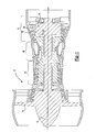
- An undercut 33 is shown beneath the platform 26 at the trailing edge 24.
- the prior art undercut 29 is shown in Figure 3 as having a single radius portion 25 connecting a lower surface 23 of the platform 26 and an upper surface 27 of a base for the blade 20.
- the purpose of the prior art undercut is to reduce thermal stress concentration in the platform.
- the area where the single radius 25 merges with the bottom surface 23 of the platform 26 remains a high thermal stress area, and may be the highest thermal stress area in this prior art blade.
- the undercut 29 does provide benefit in reducing heat stress at the platform, there is still the possibility of stress corrosion cracking and thermal mechanical fatigue.
- Figure 4 shows an inventive undercut 33.
- the undercut connecting the surfaces 23 and 27 includes three main areas.
- a first curve fillet 32 is formed at a first radius.
- a second, essentially flat or straight portion 34 is formed connecting the first fillet 32 to a second compound fillet 36.
- Compound fillet 36 begins at a point 37, and merges into surface 27.
- the compound fillet preferably extends along a transition radius.
- the surface 34 is preferably identically straight, some small deviation from straight would also be within the scope of this invention. In a broad sense, one could say that the surface 34 has less curvature than the fillets 32 or 36 and is positioned intermediate the two fillets.
- the radius for the fillet 32 is greater than the greatest radius of compound fillet 36.
- the straight surface 34 is formed at an angle X relative to a center line C of the undercut 33.
- Angle X is preferably defined parallel to a principal stress field of the platform. In one embodiment this angle was 47°.
- the radius of the fillet 32 is .115 inches (2.92mm), and the radius of the fillet 36 changes from .1 inches (2.54mm) at end 37 to .065 inches (1.65mm) adjacent the surface 27.
- the ratio between the radius of curvature for the fillet 32, and the radius of curvature for the fillet 36 at end 37 is preferably between 1 and 1.5.
- the ratio between the radius of curvature of fillet 32, and radius of curvature of fillet 36 adjacent to its opposed or bottom end is preferably 1.5 to 2.
- the angle X and the principal stress field will change dependent upon several features, including the depth of the undercut slot cut into the platform. As the undercut becomes deeper, the angle X will become shallower. On the other hand, a shallow slot will result in a steeper angle. It is expected that the range of angles will be between 40° and 60°. A ratio could be defined between the total length of the axial platform, and the depth of the undercut. An appropriate range for this ratio will be on the order of 7 to 12, with one exemplary undercut having a ratio of platform length to undercut depth of 8.8.
- the present invention moves the area of highest thermal stress away from the upper fillet 32, and moves it to be adjacent the point 37. Since this is a cooler area of the blade 20, the likelihood of stress corrosion, cracking or thermal mechanical fatigue is reduced.
- the present inventive undercut can also be utilized to refurbish airfoils having other type undercuts, or potentially even an airfoil with no undercut.
- the undercut will preferably be machined into the blade, and has a shape as shown in Figure 4.
- a computer controlled milling machine can be used. When machined in this fashion, it is possible the undercut would be flat into and out of a plane of Figure 4, which would be different than the typical undercut.
- the undercut as formed in a new blade would have some small curvature through the depth of the blade (i.e., into the plane of Figure 4). However, to simplify machining, it may well be that this curvature would be ignored when cutting an undercut.
- the method of refurbishing an air foil may incorporate an existing method wherein existing blades are cut back to blend out existing cracks. That is, when refurbishing a used blade, one may cut the inventive undercut into the blade along with a procedure for blending out any existing cracks.
- a method is generally described in U.S. Patent 6,490,791 entitled “Method for Repairing Cracks in a Turbine Blade Root Trailing Edge.”
Abstract
Description
- This invention relates to an undercut beneath the platform of a trailing edge of a turbine blade, wherein the undercut has a shape designed to move stress concentration away from the platform.
- Turbine blades typically include a platform, with an airfoil extending outwardly of the platform. The airfoil and platform are exposed to thermal stress, as they come into contact with heated gasses. The thermal stresses create design challenges for the platform.
- One method of reducing stress at the platform is the formation of an undercut at a trailing edge of the platform. The prior art undercut has generally been on a single radius. While the known undercut does reduce stress concentration, the single radius leaves a highly stressed area adjacent the portion of the radius merging into the platform.
- In a disclosed embodiment of this invention, an undercut for a turbine blade platform is formed with a shape to move thermal stress away from the interface of the undercut to the platform. In a more preferred embodiment, the shape of the undercut includes an upper fillet and a lower fillet, with an intermediate section having less curvature than either the upper or lower fillets. In a most preferred embodiment, this intermediate section is essentially straight, and connects the two fillets. The straight section is preferably formed to be parallel to a principle stress field at the highest stress location in the platform. This moves a good deal of the stress to the lower fillet. This removal of the stress from the area where the undercut merges with the platform reduces the likelihood of stress corrosion, cracking and thermal mechanical fatigue.
- These and other features of the present invention can be best understood from the following specification and drawings, the following of which is a brief description.
-
- Figure 1 shows a gas turbine engine.
- Figure 2 shows a turbine blade.
- Figure 3 shows a prior art undercut.
- Figure 4 shows the inventive undercut.
-
- As shown in Figure 1, a
gas turbine engine 10, such as a gas turbine used for power generation or propulsion, is circumferentially disposed about an engine centerline, oraxial centerline axis 12. Theengine 10 includes afan 14, acompressor 16, acombustion section 18 and aturbine 11. As is well known in the art, air compressed in thecompressor 16 is mixed with fuel which is burned in thecombustion section 18 and expanded inturbine 11. The air compressed in the compressor and the fuel mixture expanded in theturbine 11 can both be referred to as a hot gas stream flow. Theturbine 11 includesrotors 13 and 15 that, in response to the expansion, rotate, driving thecompressor 16 andfan 14. Theturbine 11 comprises alternating rows ofrotary blades 20 and static airfoils orvanes 19. Figure 1 is a somewhat schematic representation, for illustrative purposes only, and is not a limitation of the instant invention that may be employed on gas turbines used for electrical power generation and aircraft. - As shown in Figure 2,
turbine blade 20 has anairfoil portion 21 extending from a leadingedge 22 to atrailing edge 24. Aplatform 26 supports theairfoil 21. Anundercut 33 is shown beneath theplatform 26 at thetrailing edge 24. Theprior art undercut 29 is shown in Figure 3 as having asingle radius portion 25 connecting alower surface 23 of theplatform 26 and anupper surface 27 of a base for theblade 20. The purpose of the prior art undercut is to reduce thermal stress concentration in the platform. However, the area where thesingle radius 25 merges with thebottom surface 23 of theplatform 26 remains a high thermal stress area, and may be the highest thermal stress area in this prior art blade. Thus, although theundercut 29 does provide benefit in reducing heat stress at the platform, there is still the possibility of stress corrosion cracking and thermal mechanical fatigue. - Figure 4 shows an
inventive undercut 33. Here, the undercut connecting thesurfaces first curve fillet 32 is formed at a first radius. A second, essentially flat orstraight portion 34 is formed connecting thefirst fillet 32 to asecond compound fillet 36.Compound fillet 36 begins at a point 37, and merges intosurface 27. The compound fillet preferably extends along a transition radius. While thesurface 34 is preferably identically straight, some small deviation from straight would also be within the scope of this invention. In a broad sense, one could say that thesurface 34 has less curvature than thefillets - In a most preferred embodiment, the radius for the
fillet 32 is greater than the greatest radius ofcompound fillet 36. - The
straight surface 34 is formed at an angle X relative to a center line C of the undercut 33. Angle X is preferably defined parallel to a principal stress field of the platform. In one embodiment this angle was 47°. In this same embodiment, the radius of thefillet 32 is .115 inches (2.92mm), and the radius of thefillet 36 changes from .1 inches (2.54mm) at end 37 to .065 inches (1.65mm) adjacent thesurface 27. - The ratio between the radius of curvature for the
fillet 32, and the radius of curvature for thefillet 36 at end 37 is preferably between 1 and 1.5. The ratio between the radius of curvature offillet 32, and radius of curvature offillet 36 adjacent to its opposed or bottom end is preferably 1.5 to 2. - The angle X and the principal stress field will change dependent upon several features, including the depth of the undercut slot cut into the platform. As the undercut becomes deeper, the angle X will become shallower. On the other hand, a shallow slot will result in a steeper angle. It is expected that the range of angles will be between 40° and 60°. A ratio could be defined between the total length of the axial platform, and the depth of the undercut. An appropriate range for this ratio will be on the order of 7 to 12, with one exemplary undercut having a ratio of platform length to undercut depth of 8.8.
- The present invention, with its compound undercut shape, moves the area of highest thermal stress away from the
upper fillet 32, and moves it to be adjacent the point 37. Since this is a cooler area of theblade 20, the likelihood of stress corrosion, cracking or thermal mechanical fatigue is reduced. - The present inventive undercut can also be utilized to refurbish airfoils having other type undercuts, or potentially even an airfoil with no undercut. The undercut will preferably be machined into the blade, and has a shape as shown in Figure 4. A computer controlled milling machine can be used. When machined in this fashion, it is possible the undercut would be flat into and out of a plane of Figure 4, which would be different than the typical undercut. The undercut as formed in a new blade would have some small curvature through the depth of the blade (i.e., into the plane of Figure 4). However, to simplify machining, it may well be that this curvature would be ignored when cutting an undercut.
- The method of refurbishing an air foil may incorporate an existing method wherein existing blades are cut back to blend out existing cracks. That is, when refurbishing a used blade, one may cut the inventive undercut into the blade along with a procedure for blending out any existing cracks. A method is generally described in U.S. Patent 6,490,791 entitled "Method for Repairing Cracks in a Turbine Blade Root Trailing Edge."
- Although a preferred embodiment of this invention has been disclosed, a worker of ordinary skill in this art would recognize that certain modifications would come within the scope of this invention. For that reason, the following claims should be studied to determine the true scope and content of this invention.
Claims (15)
- A turbine blade (20) comprising:a platform (26), and an airfoil (21) extending outwardly of said platform (26), said airfoil (21) having a leading edge (22) and a trailing edge (24); andan undercut (33) formed on an underside of said platform (26), spaced away from said airfoil (21), said undercut (33) being on an end of said platform (26) adjacent said trailing edge (24) of said airfoil (21), and said undercut (33) connecting said underside of said platform (26) to a base of said blade (20), said undercut (33) having a shape with three distinct sections, a first section (32) adjacent said underside of said platform (26), a second section (34) connecting said first section (32) to a third section (36) adjacent said base, and said first and third sections (32,36) extending along a curve, and said second section (34) having less curvature than said first and third sections (32,36).
- A blade as set forth in claim 1, wherein said second section (34) is substantially straight.
- A blade as set forth in claim 2, wherein said second section (34) extends parallel to a principle stress field in said platform (26).
- A turbine blade (20) comprising:a platform (26), and an airfoil (21) extending outwardly of said platform (26), said airfoil (21) having a leading edge (22) and a trailing edge (24); andan undercut (33) formed on an underside of said platform (26), spaced away from said airfoil (21), said undercut (33) being on an end of said platform (26) adjacent said trailing edge (24) of said airfoil (21), and said undercut (33) connecting said underside of said platform (26) to a base of said blade (20), said undercut (33) having a shape with three distinct sections, a first section (32) adjacent said underside of said platform (26), a second section (34) connecting said first section (32) to a third section (36) adjacent said base, and said first and third sections (32,36) extending along a curve with a radius of curvature of said first section (32) being greater than a radius of curvature of said second section (34), and said second section (34) being straight and extending parallel to a principal stress field in said platform (26).
- A blade as set forth in claim 2, 3 or 4, wherein said second section (34) extends at an angle (x) of between 40° and 60°, when measured from a center line (C) of said undercut.
- A blade as set forth in any preceding claim, wherein said third section (36) is a compound curve with a changing radius.
- A blade as set forth in claim 6, wherein said changing radius transitions from a greater radius to a smaller radius from a point (37) connected to said second section (34), to a point that merges with said base.
- A blade as set forth in claim 7, wherein said first section (32) has a greater radius of curvature than said changing radii of said third section (36).
- A blade as set forth in claim 8, wherein a ratio of said radius of curvature of said first section (32) compared to said radius of curvature of said third section (36) at said point (37) connected to said second section (34) is between 1 and 1.25.
- A blade as set forth in claim 8 or 9, wherein a ratio of said radius of curvature of said first section (32) compared to said radius of curvature of said third section (36) at said point that merges into said base is between 1.5 and 2.0.
- A gas turbine engine (10) comprising:a fan (14);a compressor (16);a combustion section (18); anda turbine (11), said turbine including rotors (13,15) driving said compressor (16) and said fan (14), said rotors including blades (20), said blades being blades as set forth in any preceding claim.
- A method of refurbishing a turbine blade comprising:(1) obtaining a turbine blade (20) to be refurbished, said turbine blade having a platform (26) and an airfoil (21) extending outwardly of the platform (26), said airfoil (21) having a leading edge (22) and a trailing edge (24); and(2) forming an undercut (33) into an underside of said platform (26), spaced away from said airfoil (21), said undercut (33) being formed on an end of said platform (26) adjacent said trailing edge (24) of said airfoil (21), and said undercut (33) being formed to connect said underside of said platform (26) to a base of said blade (20), said undercut (33) being formed to have a shape with three distinct sections, a first section (32) being formed adjacent said underside of said platform (26), and a second section (34) formed to connect said first section (32) to a third section (36) formed adjacent said base, said first and third sections (32,36) being cut to extend along a curve with said second section (34) formed to have less curvature than said first and third sections (32,36).
- A method as set forth in claim 24, wherein said second section (34) is cut to be substantially straight.
- A method as set forth in claim 13, wherein said second section (34) is cut to be substantially parallel to a principal stress field in said platform (26).
- A method as set forth in claim 12, 13 or 14, wherein an undercut (33) exists in said blade prior to the forming of step (2).
Applications Claiming Priority (2)
| Application Number | Priority Date | Filing Date | Title |
|---|---|---|---|
| US10/738,288 US6951447B2 (en) | 2003-12-17 | 2003-12-17 | Turbine blade with trailing edge platform undercut |
| US738288 | 2003-12-17 |
Publications (2)
| Publication Number | Publication Date |
|---|---|
| EP1544410A1 true EP1544410A1 (en) | 2005-06-22 |
| EP1544410B1 EP1544410B1 (en) | 2009-03-11 |
Family
ID=34523167
Family Applications (1)
| Application Number | Title | Priority Date | Filing Date |
|---|---|---|---|
| EP04257869A Expired - Fee Related EP1544410B1 (en) | 2003-12-17 | 2004-12-16 | Turbine blade with trailing edge platform undercut |
Country Status (7)
| Country | Link |
|---|---|
| US (1) | US6951447B2 (en) |
| EP (1) | EP1544410B1 (en) |
| JP (1) | JP2005180431A (en) |
| KR (1) | KR20050061305A (en) |
| CN (1) | CN1629448A (en) |
| DE (1) | DE602004019872D1 (en) |
| RU (1) | RU2004137037A (en) |
Cited By (6)
| Publication number | Priority date | Publication date | Assignee | Title |
|---|---|---|---|---|
| EP1857636A1 (en) * | 2006-05-18 | 2007-11-21 | Siemens Aktiengesellschaft | Turbine blade and method for matching the platform stiffness with that of the airfoil portion |
| EP1798374A3 (en) * | 2005-12-15 | 2009-01-07 | United Technologies Corporation | Cooled turbine blade |
| EP2189662A3 (en) * | 2008-11-25 | 2012-06-27 | General Electric Company | Vane with reduced stress |
| WO2012135512A1 (en) * | 2011-04-01 | 2012-10-04 | Alstom Technology Ltd. | Turbine blade platform undercut |
| WO2014189888A1 (en) * | 2013-05-21 | 2014-11-27 | Siemens Energy, Inc. | Gas turbine engine blades and corresponding gas turbine engine |
| GB2547554A (en) * | 2016-02-19 | 2017-08-23 | Safran Aircraft Engines | Turbomachine blade, compromising a root with reduced stress concentrations |
Families Citing this family (34)
| Publication number | Priority date | Publication date | Assignee | Title |
|---|---|---|---|---|
| EP1525942A1 (en) * | 2003-10-23 | 2005-04-27 | Siemens Aktiengesellschaft | Gas turbine engine and moving blade for a turbomachine |
| US7549846B2 (en) * | 2005-08-03 | 2009-06-23 | United Technologies Corporation | Turbine blades |
| US20090208339A1 (en) * | 2008-02-15 | 2009-08-20 | United Technologies Corporation | Blade root stress relief |
| EP2093381A1 (en) | 2008-02-25 | 2009-08-26 | Siemens Aktiengesellschaft | Turbine blade or vane with cooled platform |
| EP2260181B1 (en) * | 2008-03-19 | 2016-08-17 | General Electric Technology GmbH | Guide blade having hooked fastener for a gas turbine |
| EP2265799B1 (en) * | 2008-03-19 | 2011-09-28 | Alstom Technology Ltd | Guide vane for a gas turbine |
| US8408874B2 (en) * | 2008-04-11 | 2013-04-02 | United Technologies Corporation | Platformless turbine blade |
| US8257045B2 (en) * | 2008-08-15 | 2012-09-04 | United Technologies Corp. | Platforms with curved side edges and gas turbine engine systems involving such platforms |
| US8435008B2 (en) * | 2008-10-17 | 2013-05-07 | United Technologies Corporation | Turbine blade including mistake proof feature |
| US8287241B2 (en) * | 2008-11-21 | 2012-10-16 | Alstom Technology Ltd | Turbine blade platform trailing edge undercut |
| US9840931B2 (en) * | 2008-11-25 | 2017-12-12 | Ansaldo Energia Ip Uk Limited | Axial retention of a platform seal |
| CH699998A1 (en) * | 2008-11-26 | 2010-05-31 | Alstom Technology Ltd | Guide vane for a gas turbine. |
| US8096757B2 (en) * | 2009-01-02 | 2012-01-17 | General Electric Company | Methods and apparatus for reducing nozzle stress |
| US8951013B2 (en) | 2011-10-24 | 2015-02-10 | United Technologies Corporation | Turbine blade rail damper |
| US9909425B2 (en) | 2011-10-31 | 2018-03-06 | Pratt & Whitney Canada Corporation | Blade for a gas turbine engine |
| US8689441B2 (en) | 2011-12-07 | 2014-04-08 | United Technologies Corporation | Method for machining a slot in a turbine engine rotor disk |
| US9359905B2 (en) | 2012-02-27 | 2016-06-07 | Solar Turbines Incorporated | Turbine engine rotor blade groove |
| US9017033B2 (en) | 2012-06-07 | 2015-04-28 | United Technologies Corporation | Fan blade platform |
| US10408066B2 (en) | 2012-08-15 | 2019-09-10 | United Technologies Corporation | Suction side turbine blade tip cooling |
| US9353629B2 (en) * | 2012-11-30 | 2016-05-31 | Solar Turbines Incorporated | Turbine blade apparatus |
| EP2781697A1 (en) * | 2013-03-20 | 2014-09-24 | Siemens Aktiengesellschaft | A turbomachine component with a stress relief cavity and method of forming such a cavity |
| FR3004227B1 (en) * | 2013-04-09 | 2016-10-21 | Snecma | BLOWER DISK FOR A TURBOJET ENGINE |
| EP2832952A1 (en) * | 2013-07-31 | 2015-02-04 | ALSTOM Technology Ltd | Turbine blade and turbine with improved sealing |
| US10260350B2 (en) * | 2014-09-05 | 2019-04-16 | United Technologies Corporation | Gas turbine engine airfoil structure |
| US10731484B2 (en) * | 2014-11-17 | 2020-08-04 | General Electric Company | BLISK rim face undercut |
| EP3034798B1 (en) * | 2014-12-18 | 2018-03-07 | Ansaldo Energia Switzerland AG | Gas turbine vane |
| US10167724B2 (en) * | 2014-12-26 | 2019-01-01 | Chromalloy Gas Turbine Llc | Turbine blade platform undercut with decreasing radii curve |
| US10066488B2 (en) | 2015-12-01 | 2018-09-04 | General Electric Company | Turbomachine blade with generally radial cooling conduit to wheel space |
| US10247009B2 (en) | 2016-05-24 | 2019-04-02 | General Electric Company | Cooling passage for gas turbine system rotor blade |
| CN107143381A (en) * | 2017-06-06 | 2017-09-08 | 哈尔滨汽轮机厂有限责任公司 | It is a kind of to reduce the gas turbine turbine first order movable vane piece of stress |
| KR102048874B1 (en) * | 2018-04-09 | 2019-11-26 | 두산중공업 주식회사 | Turbine vane having improved flexibility |
| US10968777B2 (en) * | 2019-04-24 | 2021-04-06 | Raytheon Technologies Corporation | Chordal seal |
| JP7284737B2 (en) * | 2020-08-06 | 2023-05-31 | 三菱重工業株式会社 | gas turbine vane |
| JP2023160018A (en) * | 2022-04-21 | 2023-11-02 | 三菱重工業株式会社 | Gas turbine rotor vane and gas turbine |
Citations (5)
| Publication number | Priority date | Publication date | Assignee | Title |
|---|---|---|---|---|
| GB1190771A (en) * | 1966-04-13 | 1970-05-06 | English Electric Co Ltd | Improvements in or relating to Turbine and Compressor Blades |
| US5387086A (en) * | 1993-07-19 | 1995-02-07 | General Electric Company | Gas turbine blade with improved cooling |
| EP0851097A2 (en) * | 1996-12-24 | 1998-07-01 | United Technologies Corporation | Turbine blade damper and seal |
| EP1128024A2 (en) * | 2000-02-23 | 2001-08-29 | Mitsubishi Heavy Industries, Ltd. | Gas turbine moving blade |
| US6390775B1 (en) * | 2000-12-27 | 2002-05-21 | General Electric Company | Gas turbine blade with platform undercut |
Family Cites Families (5)
| Publication number | Priority date | Publication date | Assignee | Title |
|---|---|---|---|---|
| US5688107A (en) * | 1992-12-28 | 1997-11-18 | United Technologies Corp. | Turbine blade passive clearance control |
| US6490791B1 (en) * | 2001-06-22 | 2002-12-10 | United Technologies Corporation | Method for repairing cracks in a turbine blade root trailing edge |
| US6607355B2 (en) * | 2001-10-09 | 2003-08-19 | United Technologies Corporation | Turbine airfoil with enhanced heat transfer |
| US20040213672A1 (en) * | 2003-04-25 | 2004-10-28 | Gautreau James Charles | Undercut leading edge for compressor blades and related method |
| US6761536B1 (en) * | 2003-01-31 | 2004-07-13 | Power Systems Mfg, Llc | Turbine blade platform trailing edge undercut |
-
2003
- 2003-12-17 US US10/738,288 patent/US6951447B2/en not_active Expired - Lifetime
-
2004
- 2004-12-03 KR KR1020040100813A patent/KR20050061305A/en active IP Right Grant
- 2004-12-13 JP JP2004360425A patent/JP2005180431A/en active Pending
- 2004-12-16 DE DE602004019872T patent/DE602004019872D1/en active Active
- 2004-12-16 EP EP04257869A patent/EP1544410B1/en not_active Expired - Fee Related
- 2004-12-16 CN CNA2004101020210A patent/CN1629448A/en active Pending
- 2004-12-17 RU RU2004137037/06A patent/RU2004137037A/en not_active Application Discontinuation
Patent Citations (5)
| Publication number | Priority date | Publication date | Assignee | Title |
|---|---|---|---|---|
| GB1190771A (en) * | 1966-04-13 | 1970-05-06 | English Electric Co Ltd | Improvements in or relating to Turbine and Compressor Blades |
| US5387086A (en) * | 1993-07-19 | 1995-02-07 | General Electric Company | Gas turbine blade with improved cooling |
| EP0851097A2 (en) * | 1996-12-24 | 1998-07-01 | United Technologies Corporation | Turbine blade damper and seal |
| EP1128024A2 (en) * | 2000-02-23 | 2001-08-29 | Mitsubishi Heavy Industries, Ltd. | Gas turbine moving blade |
| US6390775B1 (en) * | 2000-12-27 | 2002-05-21 | General Electric Company | Gas turbine blade with platform undercut |
Cited By (11)
| Publication number | Priority date | Publication date | Assignee | Title |
|---|---|---|---|---|
| EP1798374A3 (en) * | 2005-12-15 | 2009-01-07 | United Technologies Corporation | Cooled turbine blade |
| US7632071B2 (en) | 2005-12-15 | 2009-12-15 | United Technologies Corporation | Cooled turbine blade |
| EP1798374B1 (en) | 2005-12-15 | 2016-11-09 | United Technologies Corporation | Cooled turbine blade |
| EP1857636A1 (en) * | 2006-05-18 | 2007-11-21 | Siemens Aktiengesellschaft | Turbine blade and method for matching the platform stiffness with that of the airfoil portion |
| EP2189662A3 (en) * | 2008-11-25 | 2012-06-27 | General Electric Company | Vane with reduced stress |
| WO2012135512A1 (en) * | 2011-04-01 | 2012-10-04 | Alstom Technology Ltd. | Turbine blade platform undercut |
| US8550783B2 (en) | 2011-04-01 | 2013-10-08 | Alstom Technology Ltd. | Turbine blade platform undercut |
| WO2014189888A1 (en) * | 2013-05-21 | 2014-11-27 | Siemens Energy, Inc. | Gas turbine engine blades and corresponding gas turbine engine |
| GB2547554A (en) * | 2016-02-19 | 2017-08-23 | Safran Aircraft Engines | Turbomachine blade, compromising a root with reduced stress concentrations |
| US10858957B2 (en) | 2016-02-19 | 2020-12-08 | Safran Aircraft Engines | Turbomachine blade, comprising a root with reduced stress concentrations |
| GB2547554B (en) * | 2016-02-19 | 2021-03-24 | Safran Aircraft Engines | Turbomachine blade, compromising a root with reduced stress concentrations |
Also Published As
| Publication number | Publication date |
|---|---|
| EP1544410B1 (en) | 2009-03-11 |
| US20050135936A1 (en) | 2005-06-23 |
| CN1629448A (en) | 2005-06-22 |
| KR20050061305A (en) | 2005-06-22 |
| DE602004019872D1 (en) | 2009-04-23 |
| RU2004137037A (en) | 2006-05-27 |
| US6951447B2 (en) | 2005-10-04 |
| JP2005180431A (en) | 2005-07-07 |
Similar Documents
| Publication | Publication Date | Title |
|---|---|---|
| US6951447B2 (en) | Turbine blade with trailing edge platform undercut | |
| CA2535205C (en) | Crescentic ramp turbine stage | |
| EP3205820B1 (en) | End wall contour for an axial flow turbine stage | |
| AU2013201301B2 (en) | Scalloped surface turbine stage with purge trough | |
| EP1681438B1 (en) | Turbine stage with scalloped surface platform | |
| US8206115B2 (en) | Scalloped surface turbine stage with trailing edge ridges | |
| EP1270141B1 (en) | Method for repairing cracks in a turbine blade root trailing edge | |
| EP1669544A1 (en) | Turbine stage with film cooled fillet | |
| US20100158696A1 (en) | Curved platform turbine blade | |
| US10190423B2 (en) | Shrouded blade for a gas turbine engine | |
| JP2002213205A (en) | Gas turbine blade having platform with clearance groove | |
| US9297259B2 (en) | Compressor blade | |
| US20100129228A1 (en) | Turbine blade platform trailing edge undercut | |
| US10704392B2 (en) | Tip shroud fillets for turbine rotor blades | |
| CA3079182A1 (en) | Shroud interlock | |
| Lee et al. | Crescentic ramp turbine stage | |
| US20160186572A1 (en) | Turbine blade platform undercut with decreasing radii curve |
Legal Events
| Date | Code | Title | Description |
|---|---|---|---|
| PUAI | Public reference made under article 153(3) epc to a published international application that has entered the european phase |
Free format text: ORIGINAL CODE: 0009012 |
|
| AK | Designated contracting states |
Kind code of ref document: A1 Designated state(s): AT BE BG CH CY CZ DE DK EE ES FI FR GB GR HU IE IS IT LI LT LU MC NL PL PT RO SE SI SK TR |
|
| AX | Request for extension of the european patent |
Extension state: AL BA HR LV MK YU |
|
| 17P | Request for examination filed |
Effective date: 20050526 |
|
| AKX | Designation fees paid |
Designated state(s): DE FR GB |
|
| GRAP | Despatch of communication of intention to grant a patent |
Free format text: ORIGINAL CODE: EPIDOSNIGR1 |
|
| GRAS | Grant fee paid |
Free format text: ORIGINAL CODE: EPIDOSNIGR3 |
|
| GRAA | (expected) grant |
Free format text: ORIGINAL CODE: 0009210 |
|
| AK | Designated contracting states |
Kind code of ref document: B1 Designated state(s): DE FR GB |
|
| REG | Reference to a national code |
Ref country code: GB Ref legal event code: FG4D |
|
| REF | Corresponds to: |
Ref document number: 602004019872 Country of ref document: DE Date of ref document: 20090423 Kind code of ref document: P |
|
| PLBE | No opposition filed within time limit |
Free format text: ORIGINAL CODE: 0009261 |
|
| STAA | Information on the status of an ep patent application or granted ep patent |
Free format text: STATUS: NO OPPOSITION FILED WITHIN TIME LIMIT |
|
| 26N | No opposition filed |
Effective date: 20091214 |
|
| REG | Reference to a national code |
Ref country code: FR Ref legal event code: ST Effective date: 20100831 |
|
| PG25 | Lapsed in a contracting state [announced via postgrant information from national office to epo] |
Ref country code: FR Free format text: LAPSE BECAUSE OF NON-PAYMENT OF DUE FEES Effective date: 20091231 |
|
| PGFP | Annual fee paid to national office [announced via postgrant information from national office to epo] |
Ref country code: DE Payment date: 20121213 Year of fee payment: 9 |
|
| PGFP | Annual fee paid to national office [announced via postgrant information from national office to epo] |
Ref country code: GB Payment date: 20121212 Year of fee payment: 9 |
|
| REG | Reference to a national code |
Ref country code: DE Ref legal event code: R119 Ref document number: 602004019872 Country of ref document: DE |
|
| GBPC | Gb: european patent ceased through non-payment of renewal fee |
Effective date: 20131216 |
|
| REG | Reference to a national code |
Ref country code: DE Ref legal event code: R119 Ref document number: 602004019872 Country of ref document: DE Effective date: 20140701 |
|
| PG25 | Lapsed in a contracting state [announced via postgrant information from national office to epo] |
Ref country code: DE Free format text: LAPSE BECAUSE OF NON-PAYMENT OF DUE FEES Effective date: 20140701 |
|
| PG25 | Lapsed in a contracting state [announced via postgrant information from national office to epo] |
Ref country code: GB Free format text: LAPSE BECAUSE OF NON-PAYMENT OF DUE FEES Effective date: 20131216 |