EP1544725B1 - Recording apparatus and recording method - Google Patents
Recording apparatus and recording method Download PDFInfo
- Publication number
- EP1544725B1 EP1544725B1 EP04030020A EP04030020A EP1544725B1 EP 1544725 B1 EP1544725 B1 EP 1544725B1 EP 04030020 A EP04030020 A EP 04030020A EP 04030020 A EP04030020 A EP 04030020A EP 1544725 B1 EP1544725 B1 EP 1544725B1
- Authority
- EP
- European Patent Office
- Prior art keywords
- recording
- address
- addresses
- area
- inconsecutive
- Prior art date
- Legal status (The legal status is an assumption and is not a legal conclusion. Google has not performed a legal analysis and makes no representation as to the accuracy of the status listed.)
- Expired - Lifetime
Links
Images


Classifications
-
- G—PHYSICS
- G11—INFORMATION STORAGE
- G11B—INFORMATION STORAGE BASED ON RELATIVE MOVEMENT BETWEEN RECORD CARRIER AND TRANSDUCER
- G11B20/00—Signal processing not specific to the method of recording or reproducing; Circuits therefor
- G11B20/10—Digital recording or reproducing
-
- G—PHYSICS
- G11—INFORMATION STORAGE
- G11B—INFORMATION STORAGE BASED ON RELATIVE MOVEMENT BETWEEN RECORD CARRIER AND TRANSDUCER
- G11B19/00—Driving, starting, stopping record carriers not specifically of filamentary or web form, or of supports therefor; Control thereof; Control of operating function ; Driving both disc and head
- G11B19/02—Control of operating function, e.g. switching from recording to reproducing
- G11B19/04—Arrangements for preventing, inhibiting, or warning against double recording on the same blank or against other recording or reproducing malfunctions
-
- G—PHYSICS
- G11—INFORMATION STORAGE
- G11B—INFORMATION STORAGE BASED ON RELATIVE MOVEMENT BETWEEN RECORD CARRIER AND TRANSDUCER
- G11B20/00—Signal processing not specific to the method of recording or reproducing; Circuits therefor
- G11B20/10—Digital recording or reproducing
- G11B20/12—Formatting, e.g. arrangement of data block or words on the record carriers
- G11B20/1217—Formatting, e.g. arrangement of data block or words on the record carriers on discs
- G11B20/1258—Formatting, e.g. arrangement of data block or words on the record carriers on discs where blocks are arranged within multiple radial zones, e.g. Zone Bit Recording or Constant Density Recording discs, MCAV discs, MCLV discs
-
- G—PHYSICS
- G11—INFORMATION STORAGE
- G11B—INFORMATION STORAGE BASED ON RELATIVE MOVEMENT BETWEEN RECORD CARRIER AND TRANSDUCER
- G11B27/00—Editing; Indexing; Addressing; Timing or synchronising; Monitoring; Measuring tape travel
- G11B27/10—Indexing; Addressing; Timing or synchronising; Measuring tape travel
- G11B27/102—Programmed access in sequence to addressed parts of tracks of operating record carriers
- G11B27/105—Programmed access in sequence to addressed parts of tracks of operating record carriers of operating discs
-
- G—PHYSICS
- G11—INFORMATION STORAGE
- G11B—INFORMATION STORAGE BASED ON RELATIVE MOVEMENT BETWEEN RECORD CARRIER AND TRANSDUCER
- G11B27/00—Editing; Indexing; Addressing; Timing or synchronising; Monitoring; Measuring tape travel
- G11B27/10—Indexing; Addressing; Timing or synchronising; Measuring tape travel
- G11B27/19—Indexing; Addressing; Timing or synchronising; Measuring tape travel by using information detectable on the record carrier
- G11B27/24—Indexing; Addressing; Timing or synchronising; Measuring tape travel by using information detectable on the record carrier by sensing features on the record carrier other than the transducing track ; sensing signals or marks recorded by another method than the main recording
-
- G—PHYSICS
- G11—INFORMATION STORAGE
- G11B—INFORMATION STORAGE BASED ON RELATIVE MOVEMENT BETWEEN RECORD CARRIER AND TRANSDUCER
- G11B27/00—Editing; Indexing; Addressing; Timing or synchronising; Monitoring; Measuring tape travel
- G11B27/10—Indexing; Addressing; Timing or synchronising; Measuring tape travel
- G11B27/19—Indexing; Addressing; Timing or synchronising; Measuring tape travel by using information detectable on the record carrier
- G11B27/28—Indexing; Addressing; Timing or synchronising; Measuring tape travel by using information detectable on the record carrier by using information signals recorded by the same method as the main recording
- G11B27/30—Indexing; Addressing; Timing or synchronising; Measuring tape travel by using information detectable on the record carrier by using information signals recorded by the same method as the main recording on the same track as the main recording
- G11B27/3027—Indexing; Addressing; Timing or synchronising; Measuring tape travel by using information detectable on the record carrier by using information signals recorded by the same method as the main recording on the same track as the main recording used signal is digitally coded
-
- G—PHYSICS
- G11—INFORMATION STORAGE
- G11B—INFORMATION STORAGE BASED ON RELATIVE MOVEMENT BETWEEN RECORD CARRIER AND TRANSDUCER
- G11B27/00—Editing; Indexing; Addressing; Timing or synchronising; Monitoring; Measuring tape travel
- G11B27/36—Monitoring, i.e. supervising the progress of recording or reproducing
-
- G—PHYSICS
- G11—INFORMATION STORAGE
- G11B—INFORMATION STORAGE BASED ON RELATIVE MOVEMENT BETWEEN RECORD CARRIER AND TRANSDUCER
- G11B7/00—Recording or reproducing by optical means, e.g. recording using a thermal beam of optical radiation by modifying optical properties or the physical structure, reproducing using an optical beam at lower power by sensing optical properties; Record carriers therefor
- G11B7/004—Recording, reproducing or erasing methods; Read, write or erase circuits therefor
- G11B7/005—Reproducing
- G11B7/0053—Reproducing non-user data, e.g. wobbled address, prepits, BCA
-
- G—PHYSICS
- G11—INFORMATION STORAGE
- G11B—INFORMATION STORAGE BASED ON RELATIVE MOVEMENT BETWEEN RECORD CARRIER AND TRANSDUCER
- G11B7/00—Recording or reproducing by optical means, e.g. recording using a thermal beam of optical radiation by modifying optical properties or the physical structure, reproducing using an optical beam at lower power by sensing optical properties; Record carriers therefor
- G11B7/007—Arrangement of the information on the record carrier, e.g. form of tracks, actual track shape, e.g. wobbled, or cross-section, e.g. v-shaped; Sequential information structures, e.g. sectoring or header formats within a track
- G11B7/00745—Sectoring or header formats within a track
-
- G—PHYSICS
- G11—INFORMATION STORAGE
- G11B—INFORMATION STORAGE BASED ON RELATIVE MOVEMENT BETWEEN RECORD CARRIER AND TRANSDUCER
- G11B20/00—Signal processing not specific to the method of recording or reproducing; Circuits therefor
- G11B20/10—Digital recording or reproducing
- G11B2020/10935—Digital recording or reproducing wherein a time constraint must be met
- G11B2020/10981—Recording or reproducing data when the data rate or the relative speed between record carrier and transducer is variable
- G11B2020/1099—Recording or reproducing data when the data rate or the relative speed between record carrier and transducer is variable wherein a disc is spun at a variable speed
-
- G—PHYSICS
- G11—INFORMATION STORAGE
- G11B—INFORMATION STORAGE BASED ON RELATIVE MOVEMENT BETWEEN RECORD CARRIER AND TRANSDUCER
- G11B20/00—Signal processing not specific to the method of recording or reproducing; Circuits therefor
- G11B20/10—Digital recording or reproducing
- G11B20/12—Formatting, e.g. arrangement of data block or words on the record carriers
- G11B20/1217—Formatting, e.g. arrangement of data block or words on the record carriers on discs
- G11B2020/1218—Formatting, e.g. arrangement of data block or words on the record carriers on discs wherein the formatting concerns a specific area of the disc
- G11B2020/1232—Formatting, e.g. arrangement of data block or words on the record carriers on discs wherein the formatting concerns a specific area of the disc sector, i.e. the minimal addressable physical data unit
-
- G—PHYSICS
- G11—INFORMATION STORAGE
- G11B—INFORMATION STORAGE BASED ON RELATIVE MOVEMENT BETWEEN RECORD CARRIER AND TRANSDUCER
- G11B20/00—Signal processing not specific to the method of recording or reproducing; Circuits therefor
- G11B20/10—Digital recording or reproducing
- G11B20/12—Formatting, e.g. arrangement of data block or words on the record carriers
- G11B2020/1264—Formatting, e.g. arrangement of data block or words on the record carriers wherein the formatting concerns a specific kind of data
- G11B2020/1265—Control data, system data or management information, i.e. data used to access or process user data
- G11B2020/1267—Address data
- G11B2020/1269—Absolute time in pregroove [ATIP] information
-
- G—PHYSICS
- G11—INFORMATION STORAGE
- G11B—INFORMATION STORAGE BASED ON RELATIVE MOVEMENT BETWEEN RECORD CARRIER AND TRANSDUCER
- G11B20/00—Signal processing not specific to the method of recording or reproducing; Circuits therefor
- G11B20/10—Digital recording or reproducing
- G11B20/12—Formatting, e.g. arrangement of data block or words on the record carriers
- G11B2020/1264—Formatting, e.g. arrangement of data block or words on the record carriers wherein the formatting concerns a specific kind of data
- G11B2020/1265—Control data, system data or management information, i.e. data used to access or process user data
- G11B2020/1275—Calibration data, e.g. specific training patterns for adjusting equalizer settings or other recording or playback parameters
-
- G—PHYSICS
- G11—INFORMATION STORAGE
- G11B—INFORMATION STORAGE BASED ON RELATIVE MOVEMENT BETWEEN RECORD CARRIER AND TRANSDUCER
- G11B2220/00—Record carriers by type
- G11B2220/20—Disc-shaped record carriers
- G11B2220/21—Disc-shaped record carriers characterised in that the disc is of read-only, rewritable, or recordable type
- G11B2220/215—Recordable discs
- G11B2220/216—Rewritable discs
-
- G—PHYSICS
- G11—INFORMATION STORAGE
- G11B—INFORMATION STORAGE BASED ON RELATIVE MOVEMENT BETWEEN RECORD CARRIER AND TRANSDUCER
- G11B2220/00—Record carriers by type
- G11B2220/20—Disc-shaped record carriers
- G11B2220/21—Disc-shaped record carriers characterised in that the disc is of read-only, rewritable, or recordable type
- G11B2220/215—Recordable discs
- G11B2220/218—Write-once discs
-
- G—PHYSICS
- G11—INFORMATION STORAGE
- G11B—INFORMATION STORAGE BASED ON RELATIVE MOVEMENT BETWEEN RECORD CARRIER AND TRANSDUCER
- G11B2220/00—Record carriers by type
- G11B2220/20—Disc-shaped record carriers
- G11B2220/25—Disc-shaped record carriers characterised in that the disc is based on a specific recording technology
- G11B2220/2537—Optical discs
- G11B2220/2545—CDs
-
- G—PHYSICS
- G11—INFORMATION STORAGE
- G11B—INFORMATION STORAGE BASED ON RELATIVE MOVEMENT BETWEEN RECORD CARRIER AND TRANSDUCER
- G11B2220/00—Record carriers by type
- G11B2220/20—Disc-shaped record carriers
- G11B2220/25—Disc-shaped record carriers characterised in that the disc is based on a specific recording technology
- G11B2220/2537—Optical discs
- G11B2220/2562—DVDs [digital versatile discs]; Digital video discs; MMCDs; HDCDs
Definitions
- the present invention generally relates to an optical recording apparatus, a recording method and a recording apparatus for high-speed recording.
- optical information recording medium such as a write-once compact disk (CD-R), a rewriteable compact disk (CR-RW) or the like, to which a light beam is applied so that a material of a recording layer thereof is changed, and, thereby, information is recorded thereto.
- optical information recording media produced for recording at multiple speeds to which recording can be made at an arbitrary speed, and, for which it has been requested that a quality in recorded signal obtained from being recorded at a high speed is maintained, and, also, it has been requested that a quality in recorded signal obtained from being recorded at a low speed is satisfactory.
- optical information recording media which can be used only for high-speed recording result basically.
- a writing process may be forcibly performed on the recording medium after processes such as setting of a recording power through trial writing and so forth.
- US 5,862,112 discloses an optical disc and an optical disc recording reproduction device.
- the optical disc includes a first track having a spiral shape and a second track having a spiral shape.
- the first track joins the second track and information is recorded on or reproduced on the first track and the second track.
- the optical disc further includes an address region including the first address block formed so as to be on both the first track and the second track joining the first track on an inner periphery side; and a second address block formed so as to be on both the first track and the second track adjoining the first track on an outer periphery side.
- the object of US 5,862,112 is to increase the recording density on a disc.
- the addresses are consecutive and increase with each sector by 1 along a cycle.
- WO 01/27922 A1 discloses a method of hiding areas on a disc. This document is published after the filing date of the present application. According to this document, a next generation of high speed CD-RW discs for high-speed recording (4x-10x) need a new write strategy which is not suited for recording at lower speed (1x-4x). Existing CD-RW recorders may accept these discs and make recordings according to existing write strategies. This will result in readable discs. To prevent this, a power vibration area (PCA) and a program memory area (PMA), both needed for recording, are hidden for the existing recorders. As a result, the disc will be rejected. An ATIP time code jump is introduced in order to achieve the rejection.
- PCA power vibration area
- PMA program memory area
- JP 01319195 and the corresponding patent abstract of Japan disclose a time code recording and reproducing device.
- the purpose is to output a correct time code by simultaneously recording the same time code with a first head and a second head separately at plural frames. If a reading error is generated at the first head due to a dropout, the correct time code may be read by the second head since the time code has been written twice.
- This document relates to a video tape recorder or an audio tape recorder and is directed to the recording on a magnetic tape.
- US 4,360,841 is directed to a data correction circuit for correcting a digital time code reproduced from the timing track of a magnetic tape.
- Time code signals corresponding to the video signal are recorded concurrently with the video signal on the tape.
- a dropout may occur which results in a jump of the read time code.
- the object is to correct jumps which occur due to a dropout during reading but reflect jumps which have been recorded.
- the object of the invention is to provide a recording apparatus for recording information on an optical information recording medium which may comprise an inconsecutive portion of addresses. Furthermore, a corresponding method for recording information on such a recording medium shall be provided.
- a recordable optical information recording medium has addresses t for respective sectors and comprises:
- the inconsecutive part may have no sector range between an address t1' and an address t2' which are not consecutive, where t1 ⁇ t1', t2' ⁇ t2, and the starting address t1 of the area A1 may be set precedingly by the amount of (t2' - t1').
- the inconsecutive part may have a range of A1' in the direction of the physical arrangement of the sectors between addresses t1' and t2', the addresses from the address t1' to the address t2' are not consecutive, where t1 ⁇ t1', and t2' ⁇ t2, and arbitrary addresses tx may be set in the range A 1'.
- the inconsecutive part is provided, it is possible to set arbitrary addresses tx in the range of the inconsecutive part. Accordingly, it is possible to utilize the inconsecutive part by setting additional information therein.
- the inconsecutive part may have a range of A1' in the direction of the physical arrangement of the sectors between addresses t1' and t2', the addresses from the address t1' to the address t2' are not consecutive, where t1 ⁇ t1', and t2' ⁇ t2, and there may be no addresses set in the range A 1'.
- the recording medium may further comprise a pre-pit in the inconsecutive part.
- the addresses may be recorded in wobbles of a guide groove.
- the addresses are thus recorded in a form of wobbles of the guide grove of the recording medium, and a track signal is used, it is possible to specify the addresses separately from a recording signal.
- a recording apparatus comprises:
- the detecting part detects the inconsecutive part, and the correcting part performs address correction for the inconsecutivity of the addressees thereof.
- FIGS. 1 through 5 One embodiment of the present invention will now be described based on FIGS. 1 through 5. First, a sector and address structure of an advantageously used optical information recording medium I to which data recording at a high speed can be performed will now be described with reference to FIGS. 1 and 2.
- Sectors are previously formed in a recording area of the optical information recording medium 1 at least before information is recorded thereto, and an address is assigned to each sector.
- the addresses are ones which can specify the corresponding sectors, respectively.
- Information concerning these addresses are preferably recorded in a manner in which the information is modulated into wobbles of a guide groove of the optical information recording medium 1.
- ATIP Absolute Time In Pregroove
- ADIP Address In Pregroove
- the optical information recording medium 1 has at least three recordable areas A1, A2 and A3 as shown in FIG. 1.
- the area A1 is an area to which a recording apparatus accesses only at a time of recording operation (at a time of processing operation in prior to actual recording).
- An information management area for a recording apparatus or the like is one example thereof.
- an area for trial writing before recording for setting a recording power for a laser light of an optical pickup for recording (PCA (Power Calibration Area) in a CD-R disk, CD-RW disk, DVD+RW disk, or the like) corresponds to the area A1.
- This area A1 extends from a starting address t1 to an end address t2.
- the subsequent area A2 is an area to which a recording apparatus accesses at a time of recording operation and also accesses at a time of reproducing operation (at a time of processing operation in prior to actual reproducing). For example, this area is used as an area for managing recorded information in many cases.
- a PMA Program Memory Area
- This area A2 extends from a starting address t2 to an end address t3.
- the subsequent area A3 is an area to which a recording apparatus accesses at a time of recording (at a time of execution of actual recording processing) and at a time of reproducing (at a time of execution of actual reproducing processing), and an apparatus (only) for reproducing accesses at a time of reproducing.
- information (data) is actually recorded.
- a program area in a CD-R disk and a CD-RW disk corresponds to this area A3. This area A3 starts from a starting address t3.
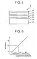
- addresses t are consecutively assigned and set according to a predetermined rule, according to a physical arrangement of sectors on the optical information recording medium. That is, a relationship between the physical arrangement of the sectors and addresses is, as shown in FIG. 6, such that, as the number of sectors increases (or decreases), the address increases, and, according to a rule particular to the recording medium, the address always changes consecutively.
- a recording apparatus detects an absolute position on the optical information recording medium from the address, and performs recording thereto.
- the sector and address structure shown in FIG. 6 is applied thereto, there is a possibility that even an apparatus produced only for recording at low speed can also perform recording thereto forcibly.
- the optical information recording medium 1 has the area A1 which is accessed only at a time of recording operation and is previously formatted so that at least one inconsecutive part at which the addresses t are not consecutive with respect to the physical arrangement of sectors is provided.
- This inconsecutive part is set between an address t1' through an address t2'.
- These addresses t1' and t2' are those such that t ⁇ t1' ⁇ t2' ⁇ t2 in the area A1.
- the addresses t1' and t2' of the inconsecutive part are determined based on a point at which a recording apparatus produced for recording at a low speed, for which recording thereto is to be prevented, accesses in the area A1. For example, when the recording apparatus produced for recording at a low speed accesses an address t0 in the area A1 at a time of recording operation, the addresses t1' and t2' are set so that the above-mentioned address t0 is in the inconsecutive part, that is, this address t0 is included between the address t1' through t2'.
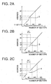
- FIGS. 2A ,2B and 2C show three typical examples in pattern of the form of the address-t inconsecutive part.
- FIG. 2A shows a pattern in which the inconsecutive part 2 has no sector range. In this example, no sectors exist between the addresses t1' and t2', as shown in FIG. 2A, and thereby the addresses are not consecutive at this inconsecutive part 2. In this case, in comparison to the address setting in the general related art shown in FIG. 6, the number of sectors included in the area A1 is smaller by the number corresponding to the addresses t1' through t2' of the inconsecutive part 2.
- the starting address t1 of the area A1 is set precedingly for this difference (reduction). Specifically, t1 - (t2' - t1') is set as the starting address of the area A1 in this case. According to this arrangement, it is possible to form the inconsecutive part 2 at which the addresses t are not consecutive without decreasing the number of useable sectors included in the area A1, and, also without providing any area in which the address t are not understandable/recognizable.
- FIG. 2B shows an example in which the inconsecutive part 3 at which the addresses t are not consecutive is formed having a range A1' in the direction of the physical arrangement of sectors.
- arbitrary addresses tx can be freely set in the range A1' of the inconsecutive part 3. Accordingly, by setting arbitrary addresses tx in the inconsecutive part 3, it is possible to cause the range A1' to have additional information using the addresses tx such as description of the type of recording medium, or the like in the inconsecutive part 3 at which the addresses t are not consecutive.
- FIG. 2C shows an example in which the inconsecutive part 4 is formed similar to the above-mentioned inconsecutive part 3 shown in FIG. 2B.
- the range A1' of the inconsecutive part 4 has no addresses t.
- the addresses are recorded through wobble modulation of a pregroove (guide groove), wobble modulation is not made, the wobbles themselves are not provided, or the pregroove itself is not provided therein.
- a pre-pit may be set in the area A1 so as to prevent track removal when the range A1' of the inconsecutive part 4 is long.
- a medium property of the optical information recording medium 1 in the embodiment of the present invention is improved so that recording thereto at a high speed can be rendered.
- a recording signal as shown in FIG. 3, a multi-pulse sequence including repetitions of heating pulses and cooling pulses, and, having the maximum mark length of 11 T.
- the recording power Pw is set arbitrarily, and, the erasing power Pe is set as 0.5Pw.
- the optical information recording medium 1 having the above-mentioned characteristics, it is possible to increase the degree of modulation at the maximum recording speed Vmax guaranteed for the recording medium, and to obtain stable characteristics of recorded signal when recording is performed at a high speed.
- a recording apparatus 5 in an embodiment of the present invention which can perform recording information to the optical information recording medium 1 to which recording can be performed at a high speed will now be described with reference to FIG. 4.
- a configuration for preventing the above-mentioned inconsecutive part 2, 3 or 4 from having any influence at a time of recording operation is provided.
- an optical pickup 7 including a laser light source, an objective lens, a photodetector and so forth for applying a light beam for recording or reproducing to the optical information recording medium I which is driven and rotated by a spindle motor 6, a read-signal processing part 8 which performs extraction of an address signal from a read signal detected by the photodetector of the optical pickup 7, an address-signal processing part 9 which performs demodulation processing on the address signal obtained from the read-signal processing part 8, an address-inconsecutivity detecting part 10 which detects whether or not address inconsecutivity exists, based on the output of the address-signal processing part 9, an address correcting part 11 which performs predetermined address correction when address inconsecutivity is detected by the address-inconsecutivity detecting part 10, and a recording-apparatus control part 12 provided for controlling the laser light source in the optical pickup 7.
- the light beam is condensed and applied to the optical information recording medium 1 which is driven and rotated by the optical pickup 7, the reflected light from the optical information recording medium 1 is received by the photodetector, and, thereby, a signal is read out from the optical information recording medium 1.
- Only an address signal is extracted from the thus-read sIgnal by the read-signal processing part 8.
- the thus-extracted address signal is demodulated by the address-sigNal processing p@rt 9, and, thereby, a point at Which the light beam is currentlx applied to the optical information recording medium 1 is specified.
- the address-inconsecutivity detecting part 10 and address correcting part 11 are provided, and address information concerning the inconsecutive part 2, 3 or 4 in the area A1 of the optical information recording medium 1 is previously recognized. Accordingly, when address inconsecutivity occurs at an access to the area A1, the address-inconsecutivity detecting part 10 recognizes that the address inconsecutivity has occurred due to the inconsecutive part 2, 3 or 4, and outputs this matter to the address correcting part 11.
- the address correcting part 11 performs address correction such that the addresses at the inconsecutive part 2, 3 or 4 are skipped, and then, outputs address information to the recording-apparatus control part 12.
- the address correcting part 11 performs address correction such that the addresses at the inconsecutive part 2, 3 or 4 are skipped, and then, outputs address information to the recording-apparatus control part 12.
- reproducing processing performed through a recording or reproducing apparatus whether it is produced for recording at a low speed or a high speed, no access to the area A1 is performed, and, access to the areas A2 and A3 in which the addresses t are set consecutively according to the physical arrangement of sectors is performed. Therefore, reproducing processing can be rendered without occurrence of any problems.
- At least the above-described processing performed by the address-inconsecutivity detecting part 10 and address correcting part 11 may be performed by a general-purpose computer as a result of instructions written in a software program including program code means for performing the processing to be executed thereby.
- the software program may be recorded in a carriable recording medium such as a CD-ROM, which is read therefrom through a CD-ROM drive, and is provided to the CPU of the computer. Then, the CPU performs the processing according to the program.
- a substrate for a CD-RW was prepared in which, on a transparent substrate made of polycarbonate, a continuous guide groove was formed spirally.
- address information (ATIP) to be recorded in the guide groove
- the inconsecutive part 2 of ATIP inconsecutivity in a form as shown in FIG. 2A was formed at the address t1' and t2' in the following manner:
- An area in which the above-mentioned inconsecutive part 2 was formed is a PCA, which is an area to which trial writing is performed with the power being changed, in order to determine the recording power Pw, at a time of recording operation, by a recording apparatus.
- the addresses t1' and t2' were determined in consideration of a position at which the recording apparatus accesses at a time of the recording operation.
- ATIP information which can be used for 1 through 4 times (1X through 4X) of a normal reproduction speed of a compact disk which is produced in accordance with the Orange Book, Part III, ver. 2.0, which is the specification of standards for CD-RW was recorded thereto.
- a lower dielectric layer 14 onto the thus-obtained transparent substrate 13, a lower dielectric layer 14, a recording layer 15, an upper dielectric layer 16, a metal reflection layer 17 and a protection layer 18 were formed.
- the optical information recording medium 1 was obtained.
- the lower and upper dielectric layers 14 and 16 were made of a mixture mainly containing ZnS and SiO 2
- the recording layer 15 was made of a phase-change material mainly containing AgInTeSb
- the metal reflection layer 17 was made of a material mainly containing A1.
- the lower and upper dielectric layers 14 and 16 were formed by RF spattering
- the recording layer 15 and metal reflection layer 17 were formed by DC spattering.
- the protection layer 18 was formed as a result of a film of a UV curing resin being deposited by spin coating, and then, UV light being applied thereto so as to cure it.
- the thus-obtained optical information recording medium 1 By initializing the thus-obtained optical information recording medium 1 through a CD-RW initializing apparatus, it was possible to obtain a not-yet-recorded CD-RW recording medium.
- Thus-obtained recording medium has the above-mentioned inconsecutive part 2 at which addresses are not consecutive formed in the PCA area.
- the above-mentioned recording apparatus was modified so as to additionally include the above-mentioned address-inconsecutivity detecting part 10 and address correcting part 11, and, then, the attempt was made to record information to the CD-RW recording medium (optical information recording medium 1) through this modified recording apparatus.
- the address correcting part 11 performed correction for the addresses for 00 : 30 : 00 in the inconsecutive part 2 which are not consecutive.
- recording operation such as trial writing and so forth was performed without occurring any problem, and, then, actual recording was started by the recording apparatus.
- the recording power Pw was determined by an OPC method which is in accordance with the Orange Book, Part III, ver. 2.0, which is the specification of standards for CD-RW.
- the optical information recording medium 1 in the embodiment of the present invention is a recording medium to which recording cannot be performed properly at a low speed such as 2X.
- the CD-RW recording medium was ejected by the recording apparatus before recording is made, similarly.
Description
- The present invention generally relates to an optical recording apparatus, a recording method and a recording apparatus for high-speed recording.
- Recently, high-speed recording has been rendered for an optical information recording medium such as a write-once compact disk (CD-R), a rewriteable compact disk (CR-RW) or the like, to which a light beam is applied so that a material of a recording layer thereof is changed, and, thereby, information is recorded thereto. Further, there are optical information recording media produced for recording at multiple speeds to which recording can be made at an arbitrary speed, and, for which it has been requested that a quality in recorded signal obtained from being recorded at a high speed is maintained, and, also, it has been requested that a quality in recorded signal obtained from being recorded at a low speed is satisfactory. Especially, according to the Part III of the Orange Book which is a specification of standards for rewriteable compact disks, high-speed recording at a speed four times through ten times, has been being standardized, in contrast to the related art in which recording is made at a speed once through four times. Further, for high-speed recording, it is difficult to apply a constant linear velocity (CLV) form to recording apparatuses in consideration of the apparatus performances. Accordingly, it is necessary to apply a constant angular velocity (CAV) form thereto. In order to apply the CAV recording form, a velocity margin approximately three times is needed for a general optical disk having a diameter of 120 mm.
- However, a margin in recording speed has reached a limit for optical information recording media. In particular, for phase-change-type optical information recording media, it has been difficult to widen the margin in recording speed in consideration of property of recording material. Accordingly, optical information recording media which can be used only for high-speed recording result basically. However, actually, when a conventional recording apparatus produced for recording at a low speed is used, and, a recording medium only for high-speed recording is inserted thereto by mistake, a writing process may be forcibly performed on the recording medium after processes such as setting of a recording power through trial writing and so forth. In such a case, due to a difference in material of optical information recording media between conventional ones for low-speed recording and new recent ones for high-speed recording, it is not possible to perform recording through the recording apparatus produced for recording at a low speed, satisfactorily. Accordingly, original data may be erroneously erased, or nonsense writing may be made.
- Accordingly, it is necessary that, even from such an optical information recording medium only for high-speed recording, reproducing of recorded data can be performed through a conventional recording apparatus or reproducing apparatus produced for recording/reproducing at a low speed in order that such a recording medium can be used generally and has a compatibility, but, to such a recording medium, recording cannot be performed through such a recording apparatus produced for recording at a low speed.
- US 5,862,112 discloses an optical disc and an optical disc recording reproduction device. The optical disc includes a first track having a spiral shape and a second track having a spiral shape. The first track joins the second track and information is recorded on or reproduced on the first track and the second track. The optical disc further includes an address region including the first address block formed so as to be on both the first track and the second track joining the first track on an inner periphery side; and a second address block formed so as to be on both the first track and the second track adjoining the first track on an outer periphery side. The object of US 5,862,112 is to increase the recording density on a disc. The addresses are consecutive and increase with each sector by 1 along a cycle.
- WO 01/27922 A1 discloses a method of hiding areas on a disc. This document is published after the filing date of the present application. According to this document, a next generation of high speed CD-RW discs for high-speed recording (4x-10x) need a new write strategy which is not suited for recording at lower speed (1x-4x). Existing CD-RW recorders may accept these discs and make recordings according to existing write strategies. This will result in readable discs. To prevent this, a power vibration area (PCA) and a program memory area (PMA), both needed for recording, are hidden for the existing recorders. As a result, the disc will be rejected. An ATIP time code jump is introduced in order to achieve the rejection.
- JP 01319195 and the corresponding patent abstract of Japan disclose a time code recording and reproducing device. The purpose is to output a correct time code by simultaneously recording the same time code with a first head and a second head separately at plural frames. If a reading error is generated at the first head due to a dropout, the correct time code may be read by the second head since the time code has been written twice. This document relates to a video tape recorder or an audio tape recorder and is directed to the recording on a magnetic tape.
- US 4,360,841 is directed to a data correction circuit for correcting a digital time code reproduced from the timing track of a magnetic tape. Time code signals corresponding to the video signal are recorded concurrently with the video signal on the tape. When reading the tape, a dropout may occur which results in a jump of the read time code. The object is to correct jumps which occur due to a dropout during reading but reflect jumps which have been recorded.
- The object of the invention is to provide a recording apparatus for recording information on an optical information recording medium which may comprise an inconsecutive portion of addresses. Furthermore, a corresponding method for recording information on such a recording medium shall be provided.
- The aforementioned object is solved by the subject matter of the
independent claims - In the following, advantages of an optical information recording media are described which may be used by the recording apparatus or recording method of the present invention:
- An optical information recording medium is produced for high-speed recording, from which reproducing recorded data can be performed through a conventional recording apparatus or reproducing apparatus produced for recording/reproducing at a low speed, but, to which recording cannot be performed by such a recording apparatus produced for recording at a low speed.
- A recordable optical information recording medium has addresses t for respective sectors and comprises:
- an area A1 starting from an address t1 to which access is made by a recording apparatus only at a time of recording operation;
- an area A2 starting from an address t2 to which access is made by the recording apparatus either at a time of recording operation or at a time of reproducing operation; and
- an area A3 starting from an address t3 to which access is made either by the recording apparatus or a reproducing apparatus either at a time of recording or at a time of reproducing, and
- wherein the addresses t are set consecutively with respect to a physical arrangement of the sectors in each of the areas A2 and A3, and the area A1 has at least one inconsecutive part at which the addresses t are not consecutive with respect to the physical arrangement of the sectors.
- In this configuration, because the addresses t are set consecutively with respect to the physical arrangement of the sectors for the areas A2 and A3 as in a normal manner, information can be reproduced even from the optical information recording medium produced for recording at a high speed through a conventional recording apparatus produced for recording at a low speed or by a reproducing apparatus. On the other hand, because the area A1 has at least one inconsecutive part at which the addresses t are not consecutive with respect to the physical arrangement of the sectors, an error occurs when the area A1 is accessed at the time of recording operation. Accordingly, it is possible to provide the optical information recording medium produced for recording at a high speed to which recording cannot be performed through a recording apparatus produced for recording at a low speed.
- The inconsecutive part may have no sector range between an address t1' and an address t2' which are not consecutive, where t1 < t1', t2' < t2, and the starting address t1 of the area A1 may be set precedingly by the amount of (t2' - t1').
- Accordingly, although the inconsecutive part is provided, no range in which the addresses are not understandable/recognizable exists, and also, it is possible to secure the area A1 equivalent to that in the case where this inconsecutive part is not provided.
- The inconsecutive part may have a range of A1' in the direction of the physical arrangement of the sectors between addresses t1' and t2', the addresses from the address t1' to the address t2' are not consecutive, where t1 < t1', and t2' < t2, and arbitrary addresses tx may be set in the range A 1'.
- Thereby, although the inconsecutive part is provided, it is possible to set arbitrary addresses tx in the range of the inconsecutive part. Accordingly, it is possible to utilize the inconsecutive part by setting additional information therein.
- The inconsecutive part may have a range of A1' in the direction of the physical arrangement of the sectors between addresses t1' and t2', the addresses from the address t1' to the address t2' are not consecutive, where t1 < t1', and t2' < t2, and there may be no addresses set in the range A 1'.
- Thereby, because no addresses exist in the inconsecutive part, it is possible to make an error positively occur at the inconsecutive part when an attempt is made to record information to the recording medium through a conventional recording apparatus produced for recording at a low speed, and, thus, to prevent writing thereto through this recording apparatus.
- The recording medium may further comprise a pre-pit in the inconsecutive part.
- Thereby, because the pre-pit is provided in the inconsecutive part, it is possible to add information in the inconsecutive part.
- The addresses may be recorded in wobbles of a guide groove.
- Because the addresses are thus recorded in a form of wobbles of the guide grove of the recording medium, and a track signal is used, it is possible to specify the addresses separately from a recording signal.
- The recording medium may be configured to have a characteristic such that, a degree of modulation is equal to or lower than 0.5 obtained when recording is made through the recording apparatus employing either an optical pickup for CD having a wavelength λ = 789 nm, and a numerical aperture of an objective lens NA = 0.50 or an optical pickup for DVD having a wavelength λ = 650 nm, and a numerical aperture of an objective lens NA = 0.60, at a relative speed V such that V = 0.5 Vmin where Vmin represents the lowest recordable relative speed between the optical pickup and the recording medium, with a recording signal of the largest mark length using a light-emitting waveform comprising a multi-pulse sequence.
- Accordingly, whether it is for CD or for DVD, the characteristic such that the degree of modulation is equal to or smaller than 0.5 is obtained when recording is made at the speed V = 0.5Vmin which is 1/2 of the lowest recording speed Vmin guaranteed for the recording medium. Therefore, recording to the recording medium cannot be performed properly through a conventional recording apparatus produced for recording at a low speed, consequently, and, as a result, an error occurs such that an OPC error is forwarded in recording of trial writing or the like. On the other hand, the recording characteristic can be improved for V ≥ Vmin for the recording medium.
- Advantageously, a recording apparatus, according to the present invention comprises:
- a detecting part which detects as to whether or not the inconsecutive part exists in the area A1 of the above-mentioned recording medium according to the present invention; and
- a correcting part which performs correction for the inconsecutive addresses thereof when the inconsecutive part is detected by the detecting part.
- In this configuration, when recording to the optical information recording medium having the inconsecutive part in the area A1 produced for recording at a high speed is performed, the detecting part detects the inconsecutive part, and the correcting part performs address correction for the inconsecutivity of the addressees thereof. Thereby, it is possible for the recording apparatus to access the area A1 without generating any problem, and to perform normal recording processing.
- Other objects and further features of the present invention will become more apparent from the following detailed description when read in conjunction with the accompanying drawings.
-
- FIG. 1 typically illustrates a sector and address structure of an optical information recording medium advantageously used by an embodiment of the present invention;
- FIGS. 2A, 2B and 2C illustrate three examples of relationship between the number of sectors and address in the advantageously used optical information recording medium;
- FIG. 3 illustrates a waveform of a recording signal used in experiments performed for the advantageously used optical information recording medium;
- FIG. 4 is a block diagram showing a general configuration of a recording apparatus in one embodiment of the present invention;
- FIG. 5 shows a side elevational sectional view of an example of the advantageously used optical information recording medium; and
- FIG. 6 shows an exmaple of relationship between the number of sectors and address in an optical information recording medium in the related general art.
- One embodiment of the present invention will now be described based on FIGS. 1 through 5. First, a sector and address structure of an advantageously used optical information recording medium I to which data recording at a high speed can be performed will now be described with reference to FIGS. 1 and 2.
- Sectors are previously formed in a recording area of the optical
information recording medium 1 at least before information is recorded thereto, and an address is assigned to each sector. The addresses are ones which can specify the corresponding sectors, respectively. Information concerning these addresses are preferably recorded in a manner in which the information is modulated into wobbles of a guide groove of the opticalinformation recording medium 1. For example, ATIP (Absolute Time In Pregroove) in CD-R disks or CD-RW disks, and ADIP (Address In Pregroove) in rewriteable DVD+RW disks are examples therefor. - The optical
information recording medium 1 has at least three recordable areas A1, A2 and A3 as shown in FIG. 1. The area A1 is an area to which a recording apparatus accesses only at a time of recording operation (at a time of processing operation in prior to actual recording). An information management area for a recording apparatus or the like is one example thereof. As an actual example, an area for trial writing before recording for setting a recording power for a laser light of an optical pickup for recording (PCA (Power Calibration Area) in a CD-R disk, CD-RW disk, DVD+RW disk, or the like) corresponds to the area A1. This area A1 extends from a starting address t1 to an end address t2. - The subsequent area A2 is an area to which a recording apparatus accesses at a time of recording operation and also accesses at a time of reproducing operation (at a time of processing operation in prior to actual reproducing). For example, this area is used as an area for managing recorded information in many cases. As an actual example, a PMA (Program Memory Area) in a CD-R disk and a CD-RW disk corresponds to this area A2. This area A2 extends from a starting address t2 to an end address t3.
- The subsequent area A3 is an area to which a recording apparatus accesses at a time of recording (at a time of execution of actual recording processing) and at a time of reproducing (at a time of execution of actual reproducing processing), and an apparatus (only) for reproducing accesses at a time of reproducing. To this area, information (data) is actually recorded. A program area in a CD-R disk and a CD-RW disk corresponds to this area A3. This area A3 starts from a starting address t3.
- For a conventional optical information recording medium produced for recording at a low speed, as shown in FIG. 6, addresses t are consecutively assigned and set according to a predetermined rule, according to a physical arrangement of sectors on the optical information recording medium. That is, a relationship between the physical arrangement of the sectors and addresses is, as shown in FIG. 6, such that, as the number of sectors increases (or decreases), the address increases, and, according to a rule particular to the recording medium, the address always changes consecutively. A recording apparatus detects an absolute position on the optical information recording medium from the address, and performs recording thereto. However, for an optical information recording medium produced for recording at a high speed, if the sector and address structure shown in FIG. 6 is applied thereto, there is a possibility that even an apparatus produced only for recording at low speed can also perform recording thereto forcibly.
- In this point, the optical
information recording medium 1 has the area A1 which is accessed only at a time of recording operation and is previously formatted so that at least one inconsecutive part at which the addresses t are not consecutive with respect to the physical arrangement of sectors is provided. This inconsecutive part is set between an address t1' through an address t2'. These addresses t1' and t2' are those such that t < t1' < t2' < t2 in the area A1. - The addresses t1' and t2' of the inconsecutive part are determined based on a point at which a recording apparatus produced for recording at a low speed, for which recording thereto is to be prevented, accesses in the area A1. For example, when the recording apparatus produced for recording at a low speed accesses an address t0 in the area A1 at a time of recording operation, the addresses t1' and t2' are set so that the above-mentioned address t0 is in the inconsecutive part, that is, this address t0 is included between the address t1' through t2'.
- A form of this address-t inconsecutive part may be set arbitrarily. FIGS. 2A ,2B and 2C show three typical examples in pattern of the form of the address-t inconsecutive part. FIG. 2A shows a pattern in which the
inconsecutive part 2 has no sector range. In this example, no sectors exist between the addresses t1' and t2', as shown in FIG. 2A, and thereby the addresses are not consecutive at thisinconsecutive part 2. In this case, in comparison to the address setting in the general related art shown in FIG. 6, the number of sectors included in the area A1 is smaller by the number corresponding to the addresses t1' through t2' of theinconsecutive part 2. Therefore, the starting address t1 of the area A1 is set precedingly for this difference (reduction). Specifically, t1 - (t2' - t1') is set as the starting address of the area A1 in this case. According to this arrangement, it is possible to form theinconsecutive part 2 at which the addresses t are not consecutive without decreasing the number of useable sectors included in the area A1, and, also without providing any area in which the address t are not understandable/recognizable. - FIG. 2B shows an example in which the
inconsecutive part 3 at which the addresses t are not consecutive is formed having a range A1' in the direction of the physical arrangement of sectors. In this case, arbitrary addresses tx can be freely set in the range A1' of theinconsecutive part 3. Accordingly, by setting arbitrary addresses tx in theinconsecutive part 3, it is possible to cause the range A1' to have additional information using the addresses tx such as description of the type of recording medium, or the like in theinconsecutive part 3 at which the addresses t are not consecutive. - FIG. 2C shows an example in which the
inconsecutive part 4 is formed similar to the above-mentionedinconsecutive part 3 shown in FIG. 2B. However, the range A1' of theinconsecutive part 4 has no addresses t. For example, in order to cause theinconsecutive part 4 to have no addresses, in a case where the addresses are recorded through wobble modulation of a pregroove (guide groove), wobble modulation is not made, the wobbles themselves are not provided, or the pregroove itself is not provided therein. When the pregroove itself is not provided therein, a pre-pit may be set in the area A1 so as to prevent track removal when the range A1' of theinconsecutive part 4 is long. In this case, it is possible to arbitrarily set information to be recorded in the pre-pit. By providing theinconsecutive part 4 having no addresses, it is possible that an error is positively caused to occur when an attempt of recording to the opticalinformation recording medium 1 is made through a recording apparatus produced for recording at a low speed, as described later. - A medium property of the optical
information recording medium 1 in the embodiment of the present invention is improved so that recording thereto at a high speed can be rendered. However, it is preferable that the following setting is made such that recording through a recording apparatus produced for recording at a low speed can be positively prevented. That is, when an optical pickup for CD of wavelength λ = 789 nm and numerical aperture of objective lens NA = 0.50 or an optical pickup for DVD of wavelength λ = 650 nm and numerical aperture of objective lens NA = 0.60 is used, it is preferable that characteristics obtained when recording is performed at a relative speed which is 1/2 of the lowest speed Vmin guaranteed for the recording medium (lowest recordable relative speed) between the pickup and recording medium, that is, V = 0.5Vmin, are as follows. In this case, as a recording signal, as shown in FIG. 3, a multi-pulse sequence including repetitions of heating pulses and cooling pulses, and, having the maximum mark length of 11 T. The recording power Pw is set arbitrarily, and, the erasing power Pe is set as 0.5Pw. In this condition, the degree of modulation m11 (= I11/Rtop, where Rtop represents the maximum reflectance for a portion at which information is not written, and I11 represents the reflectance for a portion at which the maximum mark length 11T is recorded) is measured when the signal recorded to the opticalinformation recording medium 1 is reproduced by using the optical pickup used in the recording, and the degree of modulation m11 is such that m11 ≤ 0.5. In the opticalinformation recording medium 1 having the above-mentioned characteristics, it is possible to increase the degree of modulation at the maximum recording speed Vmax guaranteed for the recording medium, and to obtain stable characteristics of recorded signal when recording is performed at a high speed. - A
recording apparatus 5 in an embodiment of the present invention which can perform recording information to the opticalinformation recording medium 1 to which recording can be performed at a high speed will now be described with reference to FIG. 4. Basically, a configuration for preventing the above-mentionedinconsecutive part recording apparatus 5, although details are omitted, anoptical pickup 7 including a laser light source, an objective lens, a photodetector and so forth for applying a light beam for recording or reproducing to the optical information recording medium I which is driven and rotated by aspindle motor 6, a read-signal processing part 8 which performs extraction of an address signal from a read signal detected by the photodetector of theoptical pickup 7, an address-signal processing part 9 which performs demodulation processing on the address signal obtained from the read-signal processing part 8, an address-inconsecutivity detecting part 10 which detects whether or not address inconsecutivity exists, based on the output of the address-signal processing part 9, anaddress correcting part 11 which performs predetermined address correction when address inconsecutivity is detected by the address-inconsecutivity detecting part 10, and a recording-apparatus control part 12 provided for controlling the laser light source in theoptical pickup 7. - In the above-mentioned configuration of the
recording apparatus 5, the light beam is condensed and applied to the opticalinformation recording medium 1 which is driven and rotated by theoptical pickup 7, the reflected light from the opticalinformation recording medium 1 is received by the photodetector, and, thereby, a signal is read out from the opticalinformation recording medium 1. Only an address signal is extracted from the thus-read sIgnal by the read-signal processing part 8. The thus-extracted address signal is demodulated by the address-sigNal processing p@rt 9, and, thereby, a point at Which the light beam is currentlx applied to the opticalinformation recording medium 1 is specified. At this time, in a recording apparatus produced for recording at a low speed in thegener 1 related art which does not have the address-inconsecutivity detecting part 10, when address inconsecutivity occurs as a result of theinconsebutive part apparatus control part 12. Accordingly, it is not possible that subsequent processing, that is, trial writing and recording processing which is to be performed in a normal state, cannot be performed. Thereby, writing of information to the opticalinformation recording medium 1 is prevented from being performed by the recording apparatus produced for recording at a low speed. - In contrast to this, in the
recording apparatus 5 in the embodiment of the present invention described with reference FIG. 4, the address-inconsecutivity detecting part 10 andaddress correcting part 11 are provided, and address information concerning theinconsecutive part information recording medium 1 is previously recognized. Accordingly, when address inconsecutivity occurs at an access to the area A1, the address-inconsecutivity detecting part 10 recognizes that the address inconsecutivity has occurred due to theinconsecutive part address correcting part 11. As a result, theaddress correcting part 11 performs address correction such that the addresses at theinconsecutive part apparatus control part 12. Thus, without being affected by the address inconsecutivity due to theinconsecutive part apparatus control part 12 or the like, trial-writing processing by accessing the area A1 (setting of the recording power Pw) and so forth is performed. Thereby, it is possible to perform recording processing to the area A3 or the like, which is to be performed in the normal state. - With regard to reproducing processing performed through a recording or reproducing apparatus, whether it is produced for recording at a low speed or a high speed, no access to the area A1 is performed, and, access to the areas A2 and A3 in which the addresses t are set consecutively according to the physical arrangement of sectors is performed. Therefore, reproducing processing can be rendered without occurrence of any problems.
- At least the above-described processing performed by the address-
inconsecutivity detecting part 10 andaddress correcting part 11 may be performed by a general-purpose computer as a result of instructions written in a software program including program code means for performing the processing to be executed thereby. The software program may be recorded in a carriable recording medium such as a CD-ROM, which is read therefrom through a CD-ROM drive, and is provided to the CPU of the computer. Then, the CPU performs the processing according to the program. - Actual examples of the above-described of the optical
information recording medium 1 described above will now be described. - A substrate for a CD-RW was prepared in which, on a transparent substrate made of polycarbonate, a continuous guide groove was formed spirally. For address information (ATIP) to be recorded in the guide groove, the
inconsecutive part 2 of ATIP inconsecutivity in a form as shown in FIG. 2A was formed at the address t1' and t2' in the following manner: - t1=96:25:10
- t1'=96:41:49
- t2'=97:11:50
- t2 = 97 : 23 : 50
- t3 = 97 : 27 : 00
- An area in which the above-mentioned
inconsecutive part 2 was formed is a PCA, which is an area to which trial writing is performed with the power being changed, in order to determine the recording power Pw, at a time of recording operation, by a recording apparatus. The addresses t1' and t2' were determined in consideration of a position at which the recording apparatus accesses at a time of the recording operation. - Further, for the area other than the
inconsecutive part 2, ATIP information which can be used for 1 through 4 times (1X through 4X) of a normal reproduction speed of a compact disk which is produced in accordance with the Orange Book, Part III, ver. 2.0, which is the specification of standards for CD-RW was recorded thereto. - Then, as shown in FIG. 5, onto the thus-obtained
transparent substrate 13, a lowerdielectric layer 14, arecording layer 15, anupper dielectric layer 16, ametal reflection layer 17 and aprotection layer 18 were formed. Thus, the opticalinformation recording medium 1 was obtained. Each of the lower and upper dielectric layers 14 and 16 were made of a mixture mainly containing ZnS and SiO2, therecording layer 15 was made of a phase-change material mainly containing AgInTeSb, and themetal reflection layer 17 was made of a material mainly containing A1. Further, the lower and upper dielectric layers 14 and 16 were formed by RF spattering, and therecording layer 15 andmetal reflection layer 17 were formed by DC spattering. Theprotection layer 18 was formed as a result of a film of a UV curing resin being deposited by spin coating, and then, UV light being applied thereto so as to cure it. - By initializing the thus-obtained optical
information recording medium 1 through a CD-RW initializing apparatus, it was possible to obtain a not-yet-recorded CD-RW recording medium. Thus-obtained recording medium has the above-mentionedinconsecutive part 2 at which addresses are not consecutive formed in the PCA area. - An experiment was performed so as to determine whether or not recording can be made to this CD-RW recording medium having the
inconsecutive part 2 at which addresses are not consecutive in the PCA area as mentioned above, through a recording apparatus (produced for recording at a low speed) available at stores. The recording apparatus used is a CD-R/RW drive MP-7060A made by Ricoh Company Ltd. When an attempt was made to record information to the CD-RW recording medium through this recording apparatus, an error occurred at an initial stage of recording operation, and the recording medium was ejected by the apparatus. - On the other hand, the above-mentioned recording apparatus was modified so as to additionally include the above-mentioned address-
inconsecutivity detecting part 10 andaddress correcting part 11, and, then, the attempt was made to record information to the CD-RW recording medium (optical information recording medium 1) through this modified recording apparatus. As a result, although inconsecutivity of ATIP exists in the PCA area due to theinconsecutive part 2, theaddress correcting part 11 performed correction for the addresses for 00 : 30 : 00 in theinconsecutive part 2 which are not consecutive. Thereby, recording operation such as trial writing and so forth was performed without occurring any problem, and, then, actual recording was started by the recording apparatus. Thus, it was confirmed that, while recording can be performed to the opticalinformation recording medium 1 through therecording apparatus 5 in the embodiment of the present invention, recording cannot be performed to the same opticalinformation recording medium 1 through the original (not modified) recording apparatus produced for recording at a low speed. - A CD-RW recording medium was produced in a manner similar to that in the case of the above-described first example. However, the composition ratio of the material of the recording layer thereof was changed so that recording at a high speed such as 4X through 8X can be performed thereon. Then, a CD-RW disk evaluating apparatus DDU1000 (λ = 789 nm, NA = 0.50) was used, and recording was performed on the thus-produced CD-RW recording medium at speeds of 8X (V = 9.6 m/s), 4X (V = 4.8 m/s) and 2X (V = 2.4 m/s) with the recording signal of multi-pulse waveform shown in FIG. 3. The recording power Pw was determined by an OPC method which is in accordance with the Orange Book, Part III, ver. 2.0, which is the specification of standards for CD-RW.
- The thus-recorded signals were read at a reproduction speed of 1X, and the above-mentioned degree of modulation m11 for each recording speed was measured. As a result, the following results were obtained:
- 8X: I11/Rtop = 0.65
- 4X: I11/Rtop = 0.56
- 2X: I11/Rtop = 0.45
- Thus, the sufficient degrees of modulation were obtained for the recording signals for the recording speeds of 8X and 4X. However, the degree of modulation was low for a low speed such as 2X in a conventional manner, and is lower than 0.55 which is the lowest standard value for CD-RW. Accordingly, the optical
information recording medium 1 in the embodiment of the present invention is a recording medium to which recording cannot be performed properly at a low speed such as 2X. - Then, when an attempt was made to write information to the above-mentioned CD-RW recording medium through the above-mentioned conventional recording apparatus which was not modified and thus does not have the address-
inconsecutivity detecting part 10 and so forth and was used for the above-mentioned first example, the CD-RW recording medium was ejected by the recording apparatus before recording is made, similarly.
Claims (7)
- A recording apparatus for recording information on an optical information recording medium which is a disk, comprising:a detecting part (10) which detects as to whether or not an inconsecutive part (2; 3; 4) for addresses t exists in an area A1 of a recording medium said area A1 being an area to which access is made by the recording apparatus only at the time of recording operation; anda correcting part (11) which performs address correction for the inconsecutive addresses thereof such that the addresses at the inconsecutive part are skipped, when the inconsecutive part is detected by said detecting part, the addresses in the inconsecutive part being inconsecutive with respect to the physical arrangement of sectors.
- A recording method for recording information on an optical information recording medium which is a disk comprising the steps of:a) detecting as to whether or not an inconsecutive part (2; 3; 4) for addresses t exists in an area A1 of the recording medium said area A1 being an area to which access is made by the recording apparatus only at the time of recording operation; andb) performing correction for the inconsecutive addresses thereof such that the addresses at the inconsecutive part are skipped, when the inconsecutive part is detected in said step a), the addresses in the inconsecutive part being inconsecutive with respect to the physical arrangement of sectors.
- The recording apparatus of claim 1 or the recording method of claim 2, wherein the recordable optical information recording medium has the addresses t for respective sectors and comprises:the area A1 starting from an address t1 to which access is made by a recording apparatus only at a time of recording operation;an area A2 starting from an address t2 to which access is made by the recording apparatus either at a time of recording operation or at a time of reproducing operation; andan area A3 starting from an address t3 to which access is made either by the recording apparatus or by a reproducing apparatus either at a time of recording or at a time of reproducing, andwherein the addresses t are set consecutively with respect to a physical arrangement of the sectors in each of said areas A2 and A3, and said area A1 has at least one inconsecutive part (2; 3; 4) at which the addresses t are not consecutive with respect to the physical arrangement of the sectors.
- The recording apparatus or recording method as claimed in one of claims 1 to 3, wherein the starting address of the area A1 is set such that the area A1 is equivalent to that in the case where the inconsecutive part is not provided.
- The recording apparatus or recording method as claimed in claim 4, wherein the inconsecutive part is between an address t1' and an address t2' which are not consecutive and wherein the starting address t1 of the area A1 is set preceedingly by the amount of (t2'-t1') with respect to the case where the inconsecutive part is not provided.
- The recording apparatus or the recording method as claimed in one of claims 1 to 5, wherein information concerning the addresses are recorded in a manner in which the information is modulated into wobbles of a guide groove before information is recorded on the information recording medium and wherein, before correcting is performed by the correcting part (1), an address information concerning the inconsecutive part is recognized by the detecting part.
- The recording apparatus or the recording method as claimed in claim 6 wherein the information concerning the addresses is ATIP information.
Applications Claiming Priority (3)
| Application Number | Priority Date | Filing Date | Title |
|---|---|---|---|
| JP2000058081 | 2000-03-03 | ||
| JP2000058081A JP3989665B2 (en) | 2000-03-03 | 2000-03-03 | Optical information recording medium |
| EP01103690A EP1130507B1 (en) | 2000-03-03 | 2001-02-23 | Prevention of low speed recording on an optical recording medium |
Related Parent Applications (2)
| Application Number | Title | Priority Date | Filing Date |
|---|---|---|---|
| EP01103690.2 Division | 2001-02-23 | ||
| EP01103690A Division EP1130507B1 (en) | 2000-03-03 | 2001-02-23 | Prevention of low speed recording on an optical recording medium |
Publications (2)
| Publication Number | Publication Date |
|---|---|
| EP1544725A1 EP1544725A1 (en) | 2005-06-22 |
| EP1544725B1 true EP1544725B1 (en) | 2006-11-02 |
Family
ID=18578729
Family Applications (5)
| Application Number | Title | Priority Date | Filing Date |
|---|---|---|---|
| EP04030020A Expired - Lifetime EP1544725B1 (en) | 2000-03-03 | 2001-02-23 | Recording apparatus and recording method |
| EP03027375A Expired - Lifetime EP1398771B1 (en) | 2000-03-03 | 2001-02-23 | Optical recording apparatus and recording method |
| EP03027376A Expired - Lifetime EP1398772B1 (en) | 2000-03-03 | 2001-02-23 | Optical information recording medium and recording apparatus |
| EP01103690A Expired - Lifetime EP1130507B1 (en) | 2000-03-03 | 2001-02-23 | Prevention of low speed recording on an optical recording medium |
| EP05022211A Expired - Lifetime EP1615120B1 (en) | 2000-03-03 | 2001-02-23 | Recording apparatus |
Family Applications After (4)
| Application Number | Title | Priority Date | Filing Date |
|---|---|---|---|
| EP03027375A Expired - Lifetime EP1398771B1 (en) | 2000-03-03 | 2001-02-23 | Optical recording apparatus and recording method |
| EP03027376A Expired - Lifetime EP1398772B1 (en) | 2000-03-03 | 2001-02-23 | Optical information recording medium and recording apparatus |
| EP01103690A Expired - Lifetime EP1130507B1 (en) | 2000-03-03 | 2001-02-23 | Prevention of low speed recording on an optical recording medium |
| EP05022211A Expired - Lifetime EP1615120B1 (en) | 2000-03-03 | 2001-02-23 | Recording apparatus |
Country Status (5)
| Country | Link |
|---|---|
| US (6) | US7068581B2 (en) |
| EP (5) | EP1544725B1 (en) |
| JP (1) | JP3989665B2 (en) |
| DE (5) | DE60118452T2 (en) |
| ES (5) | ES2275170T3 (en) |
Families Citing this family (17)
| Publication number | Priority date | Publication date | Assignee | Title |
|---|---|---|---|---|
| US6600725B1 (en) * | 1998-12-16 | 2003-07-29 | At&T Corp. | Apparatus and method for providing multimedia conferencing services with selective information services |
| JP3989665B2 (en) * | 2000-03-03 | 2007-10-10 | 株式会社リコー | Optical information recording medium |
| US7027382B2 (en) | 2001-06-26 | 2006-04-11 | Ricoh Company, Ltd. | Optical recording medium having relation between reflection layer and pit lengths |
| JP3812674B2 (en) * | 2001-09-28 | 2006-08-23 | ティアック株式会社 | Data storage disk playback device |
| US20040199780A1 (en) * | 2002-03-22 | 2004-10-07 | Heung-Chan Seung | Copy-protected optical recording medium, a method for driving therefor and a method of manufacturing thereof |
| JP3820181B2 (en) * | 2002-05-10 | 2006-09-13 | 株式会社リコー | Recording strategy generation method and optical information recording medium |
| US7106680B2 (en) * | 2002-05-10 | 2006-09-12 | Ricoh Company, Ltd. | Device and method for recording data to optical disk using multi-pulse to enhance power pulse |
| JP2004046966A (en) * | 2002-07-11 | 2004-02-12 | Ricoh Co Ltd | Optical information recording medium, recording condition deciding method, optical information recording device and information processor |
| US7351516B2 (en) * | 2002-11-06 | 2008-04-01 | Ricoh Company, Ltd. | Optical information recording medium |
| JP2004206739A (en) * | 2002-11-06 | 2004-07-22 | Ricoh Co Ltd | Method and apparatus for recording information |
| EP1439532A3 (en) * | 2003-01-17 | 2005-02-09 | Ricoh Company | Method of initializing phase change optical recording medium |
| JP2005044491A (en) * | 2003-07-10 | 2005-02-17 | Ricoh Co Ltd | Optical recording medium and its manufacturing method |
| EP1515315B1 (en) * | 2003-08-26 | 2007-07-25 | Ricoh Company, Ltd. | Information recording method, information recording device, optical information recording medium, program for recording information and storage medium |
| US7767284B2 (en) * | 2004-04-28 | 2010-08-03 | Ricoh Company, Ltd. | Optical recording medium, and, method for manufacturing the same, and method and apparatus for optical recording and reproducing thereof |
| JP4382646B2 (en) * | 2004-05-17 | 2009-12-16 | 株式会社リコー | Optical recording medium and manufacturing method thereof |
| US20060174256A1 (en) * | 2005-02-03 | 2006-08-03 | Tohru Yashiro | Optical recording medium, production method thereof, and, method and apparatus for recording and reproducing optical recording medium |
| JP3895354B2 (en) * | 2005-05-26 | 2007-03-22 | 株式会社リコー | Recording method and optical disc apparatus |
Family Cites Families (81)
| Publication number | Priority date | Publication date | Assignee | Title |
|---|---|---|---|---|
| US4041249A (en) * | 1974-12-27 | 1977-08-09 | Dictaphone Corporation | Central dictation system with privacy signal used for transcribing scanning |
| US4000510A (en) * | 1975-06-02 | 1976-12-28 | Ampex Corporation | System for storage and retrieval of video information on a cyclical storage device |
| US4301525A (en) * | 1977-03-30 | 1981-11-17 | Lanier Business Products, Inc. | Central control system for dictation |
| JPS5693159A (en) * | 1979-12-25 | 1981-07-28 | Sony Corp | Error correcting system for advance data |
| JPS5736476A (en) * | 1980-08-08 | 1982-02-27 | Sony Corp | Pcm signal recorder and reproducer |
| US4658097A (en) * | 1983-05-18 | 1987-04-14 | Dictaphone Corporation | Remote terminal for use with central dictation apparatus |
| JPH01319195A (en) * | 1988-06-20 | 1989-12-25 | Matsushita Electric Ind Co Ltd | Time code recording and reproducing device |
| US5146439A (en) * | 1989-01-04 | 1992-09-08 | Pitney Bowes Inc. | Records management system having dictation/transcription capability |
| JP2602314B2 (en) * | 1989-02-17 | 1997-04-23 | 株式会社日立製作所 | Laser beam overwriting method for phase change optical disk and apparatus for phase change optical disk using the same |
| JPH03104056A (en) | 1989-09-19 | 1991-05-01 | Hitachi Ltd | Information recording and reproducing method for rotary type information recording and reproducing device |
| JPH03161826A (en) | 1989-11-20 | 1991-07-11 | Sharp Corp | Disk type recording and reproducing device |
| US5140592A (en) * | 1990-03-02 | 1992-08-18 | Sf2 Corporation | Disk array system |
| US5166939A (en) * | 1990-03-02 | 1992-11-24 | Micro Technology, Inc. | Data storage apparatus and method |
| JP3050336B2 (en) * | 1991-07-05 | 2000-06-12 | パイオニア株式会社 | Recording method on write-once optical disc and optical disc recording apparatus |
| JPH0541046A (en) | 1991-08-02 | 1993-02-19 | Canon Inc | Information recording and reproducing device |
| EP0552985B1 (en) * | 1992-01-24 | 1998-07-08 | Pioneer Electronic Corporation | Method and apparatus for reproducing information |
| JP2860202B2 (en) | 1992-01-30 | 1999-02-24 | 株式会社ケンウッド | Recording method for rewritable optical disk |
| US5418852A (en) * | 1992-03-18 | 1995-05-23 | Fujitsu Limited | Unauthorized use prevention method for optical disks, optical disk having unauthorized use prevention function, and optical disk apparatus |
| JP3187519B2 (en) | 1992-03-19 | 2001-07-11 | 株式会社大和化成研究所 | Method for producing naphthaldehydes |
| JPH05274819A (en) | 1992-03-30 | 1993-10-22 | Sanyo Electric Co Ltd | Storage or storage reading control circuit for voice data |
| US5398220A (en) * | 1992-04-06 | 1995-03-14 | Barker; Bruce J. | Portable dictation recording device having a mechanism for transmitting recorded dictation to a remote device |
| US5818800A (en) * | 1992-04-06 | 1998-10-06 | Barker; Bruce J. | Voice recording device having portable and local modes of operation |
| US5548566A (en) * | 1992-04-06 | 1996-08-20 | Barker; Bruce J. | Dictation recording device having means for rapidly transmitting recorded dictation to a receiving device |
| JPH0638219A (en) * | 1992-07-20 | 1994-02-10 | Olympus Optical Co Ltd | Video display device |
| JP3078686B2 (en) * | 1992-10-05 | 2000-08-21 | 三菱電機株式会社 | Optical disk, optical disk drive, and optical disk write / read method |
| JP3431030B2 (en) * | 1992-11-12 | 2003-07-28 | ソニー株式会社 | Reproduction device and reproduction method |
| JPH0824522B2 (en) | 1992-11-26 | 1996-03-13 | 株式会社ケスジャン | Insecticide cartridge and insecticide device |
| JP3287648B2 (en) | 1993-06-07 | 2002-06-04 | 株式会社リコー | Simultaneous recording verification method for phase change type information recording medium and phase change type information recording drive device |
| US5535187A (en) * | 1993-12-15 | 1996-07-09 | Intenational Business Machines Corporation | High capacity run-length-limited coding system employing asymmetric and even-spaced codes |
| JP3319105B2 (en) * | 1993-12-15 | 2002-08-26 | 富士通株式会社 | Synchronous memory |
| JP3729421B2 (en) * | 1994-03-18 | 2005-12-21 | 富士通株式会社 | Unauthorized use prevention method and unauthorized use prevention system |
| JP2990011B2 (en) * | 1994-03-29 | 1999-12-13 | ティーディーケイ株式会社 | Optical recording medium |
| JP2999916B2 (en) * | 1994-03-31 | 2000-01-17 | ティーディーケイ株式会社 | Optical recording method and optical recording medium |
| US5491774A (en) * | 1994-04-19 | 1996-02-13 | Comp General Corporation | Handheld record and playback device with flash memory |
| US5898916A (en) * | 1994-06-30 | 1999-04-27 | Dictaphone Corporation | Cordless telephone for use with dictation system |
| US5477511A (en) * | 1994-07-13 | 1995-12-19 | Englehardt; C. Duane | Portable documentation system |
| US5661848A (en) * | 1994-09-08 | 1997-08-26 | Western Digital Corp | Multi-drive controller with encoder circuitry that generates ECC check bytes using the finite field for optical data for appending to data flowing to HDA |
| JP3380626B2 (en) | 1994-10-14 | 2003-02-24 | パイオニア株式会社 | Information reproducing method and apparatus |
| JP3112625B2 (en) | 1994-10-14 | 2000-11-27 | 株式会社日立製作所 | Disc recording method and reproducing apparatus |
| JP3065499B2 (en) | 1994-12-28 | 2000-07-17 | 株式会社ケンウッド | Write-once optical disc recording / reproducing device |
| US5872767A (en) * | 1995-02-17 | 1999-02-16 | Matsushita Electric Industrial Co., Ltd. | Optical disk and an optical disk recording/reproduction device having address blocks located on boundary lines between adjoining tracks |
| JP3626240B2 (en) | 1995-04-21 | 2005-03-02 | ソニー株式会社 | Dubbing equipment |
| JP2809206B2 (en) | 1995-06-26 | 1998-10-08 | 松下電器産業株式会社 | Optical disc recording / reproducing method and optical disc apparatus |
| JP3367807B2 (en) * | 1995-10-27 | 2003-01-20 | 株式会社東芝 | Optical disc playback device |
| EP0813189B1 (en) * | 1996-06-14 | 2006-05-31 | Mitsubishi Kagaku Media Co., Ltd. | Optical phase-change disc |
| JP3279182B2 (en) | 1996-06-14 | 2002-04-30 | 三菱化学株式会社 | Optical information recording medium and optical information recording method |
| ES2281101T3 (en) * | 1996-07-24 | 2007-09-16 | Koninklijke Philips Electronics N.V. | IMPROVEMENTS IN AND IN RELATION TO OPTICALLY LEGIBLE DISCS AND DISC RECORDING DEVICE. |
| JPH1092101A (en) | 1996-09-18 | 1998-04-10 | Nec Corp | Magnetic disc apparatus and its driving method |
| KR100235326B1 (en) | 1996-10-19 | 2000-01-15 | 구자홍 | Multi-rate optical disc recording method and device |
| US6022605A (en) * | 1997-02-28 | 2000-02-08 | Kao Corporation | Optical recording medium and recording/erasing method therefor |
| US5913231A (en) * | 1997-03-31 | 1999-06-15 | International Business Machines Corporation | Method and system for high speed memory address forwarding mechanism |
| JP4499193B2 (en) * | 1997-04-07 | 2010-07-07 | ソニー株式会社 | Recording / reproducing apparatus and recording / reproducing method |
| JPH1186341A (en) | 1997-09-10 | 1999-03-30 | Ricoh Co Ltd | Optical recording medium |
| JP3941185B2 (en) * | 1997-10-14 | 2007-07-04 | 松下電器産業株式会社 | Information recording / reproducing apparatus and recording gate control method |
| KR100268486B1 (en) * | 1997-11-01 | 2000-10-16 | 윤종용 | Method and apparatus for recording information on optical disc with characteristic of wavelength and reproducing from the optical disc |
| US6038199A (en) * | 1997-11-21 | 2000-03-14 | Dictaphone Corporation | Portable digital audio recorder with adaptive control configurations |
| JP4088992B2 (en) * | 1998-01-23 | 2008-05-21 | セイコーエプソン株式会社 | optical disk |
| US6310848B1 (en) * | 1998-02-10 | 2001-10-30 | Victor Company Of Japan, Ltd. | Power saving system for optical disc recording/reproducing apparatus |
| WO1999048092A2 (en) * | 1998-03-16 | 1999-09-23 | Koninklijke Philips Electronics N.V. | Optical record carrier |
| US6301211B1 (en) * | 1998-04-14 | 2001-10-09 | Hitachi, Ltd. | Information recording/reproducing apparatus |
| JP3559836B2 (en) | 1998-04-22 | 2004-09-02 | 株式会社ケンウッド | Data reading device for optical disk |
| JPH11321094A (en) | 1998-05-13 | 1999-11-24 | Ricoh Co Ltd | Phase change optical recording medium |
| JP3973318B2 (en) | 1998-05-13 | 2007-09-12 | 株式会社リコー | Optical information recording medium |
| US6049505A (en) * | 1998-05-22 | 2000-04-11 | Micron Technology, Inc. | Method and apparatus for generating memory addresses for testing memory devices |
| JP2000043418A (en) | 1998-07-31 | 2000-02-15 | Ricoh Co Ltd | Phase change type optical recording medium |
| FR2783986B1 (en) * | 1998-09-30 | 2000-12-15 | St Microelectronics Sa | METHOD AND DEVICE FOR GENERATING A CLOCK SIGNAL |
| DE69922611T2 (en) * | 1998-10-21 | 2005-11-03 | Mitsubishi Chemical Corp. | Optical recording medium and optical recording method |
| JP2000137928A (en) | 1998-10-30 | 2000-05-16 | Ricoh Co Ltd | Optical recording medium and optical recording method |
| US6282154B1 (en) * | 1998-11-02 | 2001-08-28 | Howarlene S. Webb | Portable hands-free digital voice recording and transcription device |
| JP2000251405A (en) * | 1999-02-26 | 2000-09-14 | Sanyo Electric Co Ltd | Disk recording device |
| JP4164192B2 (en) * | 1999-05-12 | 2008-10-08 | 株式会社ルネサステクノロジ | Memory device equipped with semiconductor device |
| US6470461B1 (en) * | 1999-06-07 | 2002-10-22 | Qlogic Corporation | Disk drive controller circuit and method for skipping defective and/or undesired sectors |
| US6259657B1 (en) * | 1999-06-28 | 2001-07-10 | Robert S. Swinney | Dictation system capable of processing audio information at a remote location |
| TW468162B (en) * | 1999-10-13 | 2001-12-11 | Koninkl Philips Electronics Nv | Method of hiding areas on a disc like recording of the optically rewritable type |
| US6502178B1 (en) * | 2000-02-14 | 2002-12-31 | International Business Machines Corporation | Method, system, and program for mapping logical addresses to high performance zones on a storage medium |
| JP4277452B2 (en) * | 2000-02-25 | 2009-06-10 | ソニー株式会社 | Recording device, playback device |
| JP3989665B2 (en) * | 2000-03-03 | 2007-10-10 | 株式会社リコー | Optical information recording medium |
| AU2001249797A1 (en) * | 2000-04-04 | 2001-10-15 | Contact Technology Systems, Inc. | Arc fault current interrupter testing device |
| US6553457B1 (en) * | 2000-04-19 | 2003-04-22 | Western Digital Technologies, Inc. | Tag memory disk cache architecture |
| US7038982B2 (en) * | 2001-09-27 | 2006-05-02 | Koninklijke Philips Electronics N.V. | Method and recording device for selecting an optimized write strategy and recording medium for use by the method |
| TWI220985B (en) * | 2003-07-09 | 2004-09-11 | Liteon It Corp | A control method of recording speed in optical disk drives |
-
2000
- 2000-03-03 JP JP2000058081A patent/JP3989665B2/en not_active Expired - Fee Related
-
2001
- 2001-02-23 DE DE60118452T patent/DE60118452T2/en not_active Expired - Lifetime
- 2001-02-23 ES ES04030020T patent/ES2275170T3/en not_active Expired - Lifetime
- 2001-02-23 ES ES05022211T patent/ES2271931T3/en not_active Expired - Lifetime
- 2001-02-23 EP EP04030020A patent/EP1544725B1/en not_active Expired - Lifetime
- 2001-02-23 ES ES01103690T patent/ES2261282T3/en not_active Expired - Lifetime
- 2001-02-23 EP EP03027375A patent/EP1398771B1/en not_active Expired - Lifetime
- 2001-02-23 EP EP03027376A patent/EP1398772B1/en not_active Expired - Lifetime
- 2001-02-23 ES ES03027376T patent/ES2261855T3/en not_active Expired - Lifetime
- 2001-02-23 EP EP01103690A patent/EP1130507B1/en not_active Expired - Lifetime
- 2001-02-23 ES ES03027375T patent/ES2271459T3/en not_active Expired - Lifetime
- 2001-02-23 DE DE60119587T patent/DE60119587T2/en not_active Expired - Lifetime
- 2001-02-23 DE DE60124325T patent/DE60124325T2/en not_active Expired - Lifetime
- 2001-02-23 EP EP05022211A patent/EP1615120B1/en not_active Expired - Lifetime
- 2001-02-23 DE DE60122215T patent/DE60122215T2/en not_active Expired - Lifetime
- 2001-02-23 DE DE60124327T patent/DE60124327T2/en not_active Expired - Lifetime
- 2001-02-27 US US09/793,131 patent/US7068581B2/en not_active Expired - Lifetime
-
2003
- 2003-07-17 US US10/620,692 patent/US6996041B2/en not_active Expired - Fee Related
- 2003-07-17 US US10/620,351 patent/US7072258B2/en not_active Expired - Lifetime
-
2005
- 2005-04-14 US US11/105,411 patent/US7440380B2/en not_active Expired - Fee Related
-
2006
- 2006-05-09 US US11/430,186 patent/US7539098B2/en not_active Expired - Fee Related
- 2006-05-23 US US11/438,218 patent/US7336583B2/en not_active Expired - Fee Related
Also Published As
Similar Documents
| Publication | Publication Date | Title |
|---|---|---|
| US7336583B2 (en) | Optical information recording medium and recording apparatus | |
| US7082089B2 (en) | Data recording apparatus, data recording method, and optical recording medium including pseudo-erasing features | |
| BG64405B1 (en) | Method of hiding areas on a disc like recording of the optically rewritable type | |
| US20080192598A1 (en) | Recording System For Setting Write Strategy | |
| US6765851B2 (en) | Optical disc, data-recording apparatus and data-recording method | |
| US6594214B1 (en) | Drive apparatus and method for recording and/or reproducing data and for detecting a boundary between a recorded region and a recordable region on a recording medium | |
| KR20020006427A (en) | Recording apparatus, recording medium, reproducing apparatus and discriminating method of recording medium | |
| JP3717921B2 (en) | Recording device | |
| JP2004213897A (en) | Optical information recording medium | |
| JP2007172834A (en) | Recorder and recording method | |
| JP2004030900A (en) | Recording apparatus and recording method | |
| JP2003338036A (en) | Optical information recording medium | |
| ZA200104781B (en) | Method of hiding areas of a disc like recording of the optically rewritable type. | |
| JP2005182856A (en) | Recording method of optical disk drive |
Legal Events
| Date | Code | Title | Description |
|---|---|---|---|
| PUAI | Public reference made under article 153(3) epc to a published international application that has entered the european phase |
Free format text: ORIGINAL CODE: 0009012 |
|
| 17P | Request for examination filed |
Effective date: 20041217 |
|
| AC | Divisional application: reference to earlier application |
Ref document number: 1130507 Country of ref document: EP Kind code of ref document: P |
|
| AK | Designated contracting states |
Kind code of ref document: A1 Designated state(s): DE ES FR GB IT NL |
|
| RIN1 | Information on inventor provided before grant (corrected) |
Inventor name: KATO, MASAKI Inventor name: NAKAMURA, YUKI Inventor name: YAMADA, KATSUYUKI |
|
| RTI1 | Title (correction) |
Free format text: OPTICAL RECORDING APPARATUS AND RECORDING METHOD |
|
| AKX | Designation fees paid |
Designated state(s): DE ES FR GB IT NL |
|
| RTI1 | Title (correction) |
Free format text: RECORDING APPARATUS AND RECORDING METHOD |
|
| GRAP | Despatch of communication of intention to grant a patent |
Free format text: ORIGINAL CODE: EPIDOSNIGR1 |
|
| RIN1 | Information on inventor provided before grant (corrected) |
Inventor name: NAKAMURA, YUKI Inventor name: KATO, MASAKI Inventor name: YAMADA, KATSUYUKI |
|
| GRAS | Grant fee paid |
Free format text: ORIGINAL CODE: EPIDOSNIGR3 |
|
| GRAA | (expected) grant |
Free format text: ORIGINAL CODE: 0009210 |
|
| AC | Divisional application: reference to earlier application |
Ref document number: 1130507 Country of ref document: EP Kind code of ref document: P |
|
| AK | Designated contracting states |
Kind code of ref document: B1 Designated state(s): DE ES FR GB IT NL |
|
| PG25 | Lapsed in a contracting state [announced via postgrant information from national office to epo] |
Ref country code: IT Free format text: LAPSE BECAUSE OF FAILURE TO SUBMIT A TRANSLATION OF THE DESCRIPTION OR TO PAY THE FEE WITHIN THE PRESCRIBED TIME-LIMIT;WARNING: LAPSES OF ITALIAN PATENTS WITH EFFECTIVE DATE BEFORE 2007 MAY HAVE OCCURRED AT ANY TIME BEFORE 2007. THE CORRECT EFFECTIVE DATE MAY BE DIFFERENT FROM THE ONE RECORDED. Effective date: 20061102 |
|
| REG | Reference to a national code |
Ref country code: GB Ref legal event code: FG4D |
|
| REF | Corresponds to: |
Ref document number: 60124325 Country of ref document: DE Date of ref document: 20061214 Kind code of ref document: P |
|
| ET | Fr: translation filed | ||
| REG | Reference to a national code |
Ref country code: ES Ref legal event code: FG2A Ref document number: 2275170 Country of ref document: ES Kind code of ref document: T3 |
|
| PLBE | No opposition filed within time limit |
Free format text: ORIGINAL CODE: 0009261 |
|
| STAA | Information on the status of an ep patent application or granted ep patent |
Free format text: STATUS: NO OPPOSITION FILED WITHIN TIME LIMIT |
|
| 26N | No opposition filed |
Effective date: 20070803 |
|
| PGFP | Annual fee paid to national office [announced via postgrant information from national office to epo] |
Ref country code: ES Payment date: 20140219 Year of fee payment: 14 Ref country code: IT Payment date: 20140227 Year of fee payment: 14 |
|
| PG25 | Lapsed in a contracting state [announced via postgrant information from national office to epo] |
Ref country code: IT Free format text: LAPSE BECAUSE OF NON-PAYMENT OF DUE FEES Effective date: 20150223 |
|
| REG | Reference to a national code |
Ref country code: FR Ref legal event code: PLFP Year of fee payment: 16 |
|
| REG | Reference to a national code |
Ref country code: ES Ref legal event code: FD2A Effective date: 20160329 |
|
| PG25 | Lapsed in a contracting state [announced via postgrant information from national office to epo] |
Ref country code: ES Free format text: LAPSE BECAUSE OF NON-PAYMENT OF DUE FEES Effective date: 20150224 |
|
| REG | Reference to a national code |
Ref country code: FR Ref legal event code: PLFP Year of fee payment: 17 |
|
| REG | Reference to a national code |
Ref country code: FR Ref legal event code: PLFP Year of fee payment: 18 |
|
| PGFP | Annual fee paid to national office [announced via postgrant information from national office to epo] |
Ref country code: NL Payment date: 20190218 Year of fee payment: 19 |
|
| PGFP | Annual fee paid to national office [announced via postgrant information from national office to epo] |
Ref country code: GB Payment date: 20190218 Year of fee payment: 19 Ref country code: DE Payment date: 20190219 Year of fee payment: 19 |
|
| PGFP | Annual fee paid to national office [announced via postgrant information from national office to epo] |
Ref country code: FR Payment date: 20190219 Year of fee payment: 19 |
|
| REG | Reference to a national code |
Ref country code: DE Ref legal event code: R119 Ref document number: 60124325 Country of ref document: DE |
|
| REG | Reference to a national code |
Ref country code: NL Ref legal event code: MM Effective date: 20200301 |
|
| GBPC | Gb: european patent ceased through non-payment of renewal fee |
Effective date: 20200223 |
|
| PG25 | Lapsed in a contracting state [announced via postgrant information from national office to epo] |
Ref country code: NL Free format text: LAPSE BECAUSE OF NON-PAYMENT OF DUE FEES Effective date: 20200301 |
|
| PG25 | Lapsed in a contracting state [announced via postgrant information from national office to epo] |
Ref country code: DE Free format text: LAPSE BECAUSE OF NON-PAYMENT OF DUE FEES Effective date: 20200901 Ref country code: FR Free format text: LAPSE BECAUSE OF NON-PAYMENT OF DUE FEES Effective date: 20200229 Ref country code: GB Free format text: LAPSE BECAUSE OF NON-PAYMENT OF DUE FEES Effective date: 20200223 |