EP1545353B1 - Pedicle screw connector apparatus - Google Patents
Pedicle screw connector apparatus Download PDFInfo
- Publication number
- EP1545353B1 EP1545353B1 EP03733832A EP03733832A EP1545353B1 EP 1545353 B1 EP1545353 B1 EP 1545353B1 EP 03733832 A EP03733832 A EP 03733832A EP 03733832 A EP03733832 A EP 03733832A EP 1545353 B1 EP1545353 B1 EP 1545353B1
- Authority
- EP
- European Patent Office
- Prior art keywords
- connector
- rod
- conical surface
- band
- rods
- Prior art date
- Legal status (The legal status is an assumption and is not a legal conclusion. Google has not performed a legal analysis and makes no representation as to the accuracy of the status listed.)
- Expired - Lifetime
Links
Images


Classifications
-
- A—HUMAN NECESSITIES
- A61—MEDICAL OR VETERINARY SCIENCE; HYGIENE
- A61B—DIAGNOSIS; SURGERY; IDENTIFICATION
- A61B17/00—Surgical instruments, devices or methods, e.g. tourniquets
- A61B17/56—Surgical instruments or methods for treatment of bones or joints; Devices specially adapted therefor
- A61B17/58—Surgical instruments or methods for treatment of bones or joints; Devices specially adapted therefor for osteosynthesis, e.g. bone plates, screws, setting implements or the like
- A61B17/68—Internal fixation devices, including fasteners and spinal fixators, even if a part thereof projects from the skin
- A61B17/70—Spinal positioners or stabilisers ; Bone stabilisers comprising fluid filler in an implant
- A61B17/7001—Screws or hooks combined with longitudinal elements which do not contact vertebrae
- A61B17/7035—Screws or hooks, wherein a rod-clamping part and a bone-anchoring part can pivot relative to each other
- A61B17/7038—Screws or hooks, wherein a rod-clamping part and a bone-anchoring part can pivot relative to each other to a different extent in different directions, e.g. within one plane only
Landscapes
- Health & Medical Sciences (AREA)
- Orthopedic Medicine & Surgery (AREA)
- Life Sciences & Earth Sciences (AREA)
- Neurology (AREA)
- Surgery (AREA)
- Heart & Thoracic Surgery (AREA)
- Engineering & Computer Science (AREA)
- Biomedical Technology (AREA)
- Nuclear Medicine, Radiotherapy & Molecular Imaging (AREA)
- Medical Informatics (AREA)
- Molecular Biology (AREA)
- Animal Behavior & Ethology (AREA)
- General Health & Medical Sciences (AREA)
- Public Health (AREA)
- Veterinary Medicine (AREA)
- Surgical Instruments (AREA)
- Dowels (AREA)
- Joining Of Building Structures In Genera (AREA)
Abstract
Description
- This invention relates generally to securement devices and, more particularly, to a coupling and locking mechanism that is used to secure two rods together, or to secure a rod to one or more pedicle screws.
- Spinal fusion surgery is a method of placing bone graft material between two mobile segments of the spine to knit them together as one unit and eliminate motion between the segments. Fusion surgery can be performed with or without the use of spinal instrumentation for internal fixation. Internal fixation instruments are used to provide stability to decrease motion between segments of the spine and to allow the bone fusion to knit together. They act as an internal splint. Internal fixation devices may be attached with hooks, wires or bone screws. When bone screws or pedicle screws are employed they are screwed into the pedicles of a vertebra and connected to rods or plates to stabilize movement between the vertebrae to which they are connected. Thus, pedicle screws are implants used in the thoracic and lumbar spine to help surgeons stabilize the spine. "Headless" pedicle screws are used for several reasons, including the fact that headless screw design has been known to make it easier for surgeons to implant pedicle screws while avoiding the facet joint. In addition, pedicle screws can be implanted at each spinal level.
- One such headless pedicle screw is the screw associated with TSRH-3D™ manufactured by Medtronic Sofamor Danek. More particularly, the present invention is capable of working in conjunction with "bolt 88" disclosed in
U.S. Pat. Nos. 5,643,263 and5,885,285 to Simonson . The present invention is a replacement for the clamp found inU.S. Pat. Nos. 5,643,263 and5,885,285 to Simonson . Details of the TSRH spinal implant system are disclosed in the "Surgical Technique Manual" provided by Danek Medical, Inc., published in 1990. - The use of fixation devices for the treatment of vertebrae deformities and injuries is well known in the art. Various fixation devices are used in medical treatment to correct curvatures and deformities, treat trauma and remedy various abnormal spinal conditions. Treatment of these conditions generally requires the implantation of various component pieces such as support rods, crosslinks, caudal facing hooks, cranial facing hooks and like components, which form a spinal implant system.
- It is necessary in spinal implant systems to properly anchor the system to bone to provide necessary support of the implant. Bone screws are commonly used for anchoring spinal implant systems. There are, however, several problems with the use of fixed screws for anchoring spinal implants. The exact final position of a bone screw is difficult, if not impossible, to predict prior to the exposure of the patient's bone. This unpredictability results from the uncertainty of exact bone formation and shape within an individual patient. Additionally, it can be difficult to predetermine the structure of the bone, i.e. whether the bone is soft or even osteoporotic. Even if the final position of the screw can be predetermined, the necessary shape and position of a spinal rod implant may create unwanted stress upon the bone screw or the bone itself. This is especially true where a plurality of screws is required along the spinal column for securement of an implant. The alignment of the rod with several screws along the vertebrae compounds this problem and makes undesired stress much more probable. Moreover, this misalignment may influence the extent and speed of correction of the spinal defect.
- With regard to the size of a bone screw and connector, a low profile arrangement provides less disruption of the tissues in the vicinity of the spine. Nonetheless, it is common in the insertion of spinal implants to necessarily remove portions of vertebral bone to allow proper insertion of a bone screw. Moreover, current systems in use may result in long-term muscular displacement that may lead to a patient's pain or discomfort. Thus, a low profile bone screw and connector offers advantages, including less post-operative pain and discomfort for the patient.
- Increased complexity of the installation procedure is undesirable because it increases a patient's time in surgery. Increased operating time is known to increase the risk of many complications associated with surgery. The additional time necessary to remove, or even temporarily dislocate, bone or muscular tissue also increases operating time, and thus the risk of complications.
- In view of the above, there is a long felt but unsolved need for a system that avoids the above-mentioned deficiencies of the prior art and that provides an effective system that is relatively simple to employ and requires minimal displacement or removal of bodily tissue.
-
US-A-5 997 539 (the preamble ofclaim 1 is based on this document) discloses a polyaxial orthopedic device for use with rod implant apparatus including a screw having a curvate ball top, a polyaxial head member having a socket into which the head of the screw is initially polyaxially nested, a vertical slot which renders the socket compressible, and a horizontal through hole having a tapered portion on one side of the vertical slot. A rod gripping cross-bar member, which is mounted through the through hole includes an axial split which permits the first end thereof to grip a rod, and then to be clamped onto the rod when the axial slot is narrowed. A nut is provided on the end of the cross-bar member which extend out from the through hole on the opposite end from the rod gripping mechanism. The advancement of the nut causes the cross-bar member to be compressed by the taper of the front portion of the through hole, thereby locking the rod in the gripping end thereof, and further provides the compression force necessary to compression lock the interior socket of the head against the ball top of the screw. -
US-A-5 746 741 discloses an external fixator system comprising a clamp adapted to couple a fixator pin to a connecting rod. The clamp includes a slot for transversely receiving the body of the connecting rod. The slot preferably includes a region of reduced width, providing interference between the clamp and the connecting rod as it is inserted. This causes the clamp to snap onto the rod. A bolt is inserted through a hole passing through both sides of the slot. The bolt includes a head at one end formed in the shape of a hook adapted to hook the shaft of a fixator pin, and a thread at the opposite end. The bolt is rotatably mountable in the hole such that the fixator pin can be retained at a range of angles relative to the connecting rod. The clamp is attachable to a fixator pin and a connecting bar between two previously-installed clamps without disassembly of the system. - In accordance with the present invention, a low-profile connector device is provided for attaching two cylindrical objects or rods together, such as a spinal rod implant and the shaft of a pedicle screw used in spinal stabilization surgeries. The present invention is a variable angle connector that allows single point clamping. More particularly, after the rods are inserted into the receptacles of the connector, they may be moved longitudinally within the receptacles, and they may be rotated within the receptacles. Subsequently, a single tightening screw is advanced within the connector to secure all degrees of freedom. The action of the tightening screw on the connector creates forces within the connector that secure and fixedly interconnect both of the rods within the connector, thus setting the connector and the rods in an interlocked final position.
- In a first aspect of the invention, a connector is presented for securing two rods. The connector comprises a body including a first substantially conical surface having a slit and opposing joining sections adjacent the slit. In addition, the connector includes first and second receptacles for receiving first and second rods, respectively. The connector also includes a second substantially conical surface that is operatively associated with the first substantially conical surface. Finally, the connector includes means for urging the joining sections toward each other. Tension force is created within the connector upon urging the opposing joining sections in closer proximity because narrowing the slit reduces the diameter of the first substantially conical surface, which in turn pushes down on the second substantially conical surface. The tension force causes the two rods to be secured within the connector's receptacles because the receptacles create constricting or compressive forces around the rods. As an example of use in spinal surgery, one rod may take the form of a shaft of a pedicle screw, while the other rod is a stabilization rod that bridges a problematic spinal disc. The connector may be of unitary or one-piece construction, or it may be formed of a plurality of parts, such as two-part construction. In a preferred embodiment, the receptacles are formed of bands that are interconnected.
- In a second aspect of the invention, a two-member connector is presented for securing two rods. Here, the connector includes a first member having a first receptacle for one of the rods, a first substantially conical surface having a slit and opposing joining sections adjacent the slit. The connector also has a second member that includes a second receptacle for a second rod, and a second conical surface for contacting the first conical surface. Finally, the connector includes means for forcing the joining sections toward each other, wherein the two rods are secured within the connector upon forcing the joining sections toward each other.
- In yet a separate aspect of the invention, a connector for securing two rods is presented. The connector includes a first member having an interior substantially conical surface having a slit and adjacent opposing joining sections. The first member also has a first rod band at least partially disposed through a center opening in the first member. In addition, the connector has a second member including an exterior substantially conical surface and a second rod band that is also at least partially disposed through a central opening in the second member. Means for interconnecting the first rod band to the second rod band are provided, such as by threading the two bands together. In addition, means for forcing the opposing joining sections toward each other are also provided, such as by using a threaded tightening screw.
- In yet a separate aspect of the invention, an end connector is provided that utilizes an end position on the end of a rod to form at least a portion of the connector of the present invention. The end connector includes two substantially conical surface members where one of the conical surfaces is formed as an integral part of the end of the rod. Among other things, this aspect of the invention allows for further controlling the eccentricity of the connector, as well as reducing the size of the connector because a second receptacle or rod band is not necessary given that the rod is already connected to the end connector. The end connector functions in a manner similar to the other connectors described herein. More particularly, a slit along the first substantially conical surface is narrowed by using a tightening screw to pull the two opposing joining sections of the slit toward each other. This ultimately results in creating a compression force around the rod band that holds the pedicle screw, thereby securing the pedicle screw to the rod.
- In yet a separate aspect of the invention, a connector is provided that includes a plurality of pieces, and more particularly, a connector having four pieces is described. The four- piece connector includes first and second rod receiving members, and first and second substantially conical surface members. One of the conical surface members includes a slit and opposing joining sections adjacent the slit. Means for urging the joining sections toward each other is also provided, such as a tightening screw. The rod receiving members force the rods inserted therein to impinge upon the conical surface members, thereby securing the rods within the connector.
- In a separate aspect of the invention, a projection or surface texturing may be provided within a receptacle or rod band of the connector, and also potentially provided on the shaft of the screw or the rod to provide additional stability to the assembly.
- Based on the foregoing summary, a number of worthwhile aspects of the present invention can be readily identified. The minimal size of the connector device allows attachment of the device to human bone without significant displacement of human tissue. Therefore, the complexity of surgery and the following pain and discomfort of the patient may be minimized. The nature of the device, combined with its small size and profile, may allow a surgeon to attach the securement device to a secure portion of the human body without the need to remove bony processes which may be necessary to accommodate a larger attachment device. The simplicity of the elements, and the assembly process thereof reduces the training and experience or surgeons necessary to achieve desired results, and, may reduce the patient's time in surgery, thus reducing the risk and probability of surgical complications. Finally, a number of embodiments of the present invention may be used in combination to allow a surgeon great latitude in the selection of materials used. The surgeon may select from different embodiments of the connector to best fit the surgical implant parameters. With these choices, the surgeon may then best determine which embodiments of which elements to select to minimize removal or displacement of bodily tissue or bone, and thereby reduce both the patient's risk of surgical complications and post-surgical pain and discomfort.
- A significant feature of the present invention is the ability to provide a construct used to stabilize the spine or a portion thereof. This is a very low profile configuration (as compared to existing devices) that minimizes the length of the incision that is necessary to perform the surgery. Furthermore, a mechanical advantage is gained by the interaction of the components as previously described. Specifically, strength of the final connection is not simply attributable to the tightening of the tightening screw, but is also attributable, in part, to the placement of the spinal rod or screw shaft within the receptacles of the connector, and the wedge like interaction of the conical surfaces of the connector.
- Additional advantages of the present invention will become readily apparent from the following discussion, particularly when taken together with the accompanying drawings.
-
-
Fig. 1 is a side elevation view of a first embodiment of the present invention; -
Fig. 2A is a is a top view of a first member of a two-piece connector; -
Fig. 2B is a bottom view of the first member shown inFig. 2A ; -
Fig. 2C is a side elevation view of the first member shown inFig. 2A ; -
Fig. 2D is a second side elevation view of the first member shown inFig. 2A ; -
Fig. 3A is a side elevation view of a second member of a two-piece connector; -
Fig. 3B is a bottom view of the second member shown inFig. 3A ; -
Fig. 3C is a second side elevation view of the second member shown inFig. 3A ; -
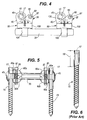
Fig. 4 is a plan view of two connectors used to connect pedicle screws to a stabilizing rod; -
Fig. 5 is a side view of the apparatus depicted inFig. 4 ; -
Fig. 6 is a pedicle screw known in the prior art; -
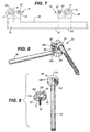
Fig. 7 is a plan view of two connectors, including an end connector formed as an integral part of a rod, wherein the connectors are used to connect pedicle screws to a stabilizing rod; -
Fig. 8 is a perspective view of an end connector formed as an integral part of a rod; -
Fig. 9 is a perspective view of a two-piece end connector formed as an integral part of a rod; -
Fig. 10 is a different a perspective view than that ofFig. 9 of a two-piece end connector formed as an integral part of a rod; -
Fig. 11 is a different perspective view than that ofFig. 8 of an end connector formed as an integral part of a rod; -
Fig. 12 is a different perspective view than that ofFigs. 8 or11 of an end connector formed as an integral part of a rod; -
Fig. 13 is a side elevation view of two connectors of the present invention used to bridge a problematic vertebral disc; -
Fig. 14 is a plan view of an incision showing implantation of two connectors and a rod; -
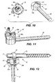
Fig. 15 is an elevation view of an exploded four-piece connector of the present invention; -
Fig. 16 is a top view of a component of the four-piece connector shown inFig. 15 ; -
Fig. 17A is a bottom view of a separate component of the four-piece connector shown inFig. 15 ; -
Fig. 17B is a top view of the component shown inFig. 17A ; -
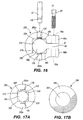
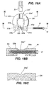
Fig. 18A is a top view component of a separate embodiment of a multi-piece connector; -
Fig. 18B is a cross-section alongline 18B-18B as shown inFig. 18A ; -
Fig. 18C is second cross-section alongline 18C-18C as shown inFig. 18A ; - Referring to
Fig. 1 , a first embodiment of the connector of the present invention is shown. Theconnector 10 includes afirst rod band 45 and asecond rod band 105. In addition, the connector includes substantially conical surfaces within the interior of the connector. Finally, the connector includes a slit and a means for drawing together the adjacent joining sections of the slit, thereby decreasing the diameter of the upper conical surface that in turn forces the lower conical surface downwards, thereby tightening thebands - Referring now to
Figs. 2A-3C , a first embodiment of theconnector 10 of the present invention is shown, wherein the connector is formed of two pieces. However it is to be understood that the present invention may be of unitary construction, or it may be constructed of a plurality of pieces, such as three or four pieces, as will be discussed below. - In a first embodiment,
connector 10 utilizes two-piece construction, wherein the first piece isfirst member 35.First member 35 shown inFigs. 2A-2D includes afirst body 40,first rod band 45, first band fitting 50, slit 55, opposing joiningsections openings conical surface 70, andcenter body opening 75.First body 40 is preferably circular, although its exterior surface may be other shapes, such as square, rectangular, or a multi-side polyhedron. One end offirst rod band 45 is connected tofirst body 40.First rod band 45 forms a loop along its length, thereby creating an opening or afirst rod position 80. Asfirst rod band 45 curves, it is disposed throughcenter body opening 75 and extends below interior substantiallyconical surface 70. At the end of the portion offirst rod band 45 that is disposed through center body opening 75 is first band fitting 50. First band fitting 50 is preferably an interconnection device that allowsfirst member 35 to be interconnected to the second piece ofconnector 10, as will be discussed below. First band fitting 50 includes interconnection means, such as threads, a hook, or a socket, that receives, or is received in, the second piece ofconnector 10. Joiningsections section 60a toward joiningsection 60b. Preferably, joiningsections openings screw 85. Whenconnector 10 is installed, as will be discussed below, tighteningscrew 85 is placed throughopenings section 60a closer to joiningsection 60b. More particularly, due to the presence ofslit 55 infirst body 40 between joiningsections screw 85 is used to pull joiningsection 60a toward joiningsection 60b. - Referring now to
Figs. 3A through 3C , thesecond member 90 ofconnector 10 is illustrated.Second member 90 includes asecond body 100,second rod band 105, second rod band fitting 110, exterior substantiallyconical surface 115, and secondcentral body opening 120.Second body 100 is preferably circular, although its exterior surface may be other shapes, such as square, rectangular, or a multi-side polyhedron, as long as the upper exterior surface is substantially conical, that is, exterior substantiallyconical surface 115. One end ofsecond rod band 105 is interconnected tobody 100.Second rod band 105 forms a loop along its length, thereby creating an opening or asecond rod position 125. Assecond rod band 105 curves, it is disposed through or in the vicinity ofcenter body opening 120. At the end ofsecond rod band 105 is second band fitting 110. Similar to first band fitting 50, second band fitting 110 is preferably an interconnection device that allowsfirst member 35 to be interconnected tosecond member 90. More particularly,first rod band 45 is connected tosecond rod band 105. Accordingly, second band fitting 110 must mate with first band fitting 50. Preferably, the interconnection means includes threads, a hook, or a socket, an expansion fitting or some type of connection that interconnects first band fitting 50 with second band fitting 110. For example, preferably first band fitting 50 may be fitted with male threads and second band fitting 110 with matching female threads. Alternately, first band fitting 50 may be fitted with a T-shaped interlocking fitting (not shown) that can be pushed into an opening in second band fitting 110 and turned 90 degrees to lock the two pieces together. Rotational freedom between rods is provided when using a threaded connection between thefirst rod band 45 andsecond rod band 105 because the threads can be partially released with the rods situated within the connector to adjust the connector to accommodate the position of the first rod (or pedicle screw shaft) relative to the second rod (or spinal stabilization rod). At least approximately 60 degrees of rotational freedom exists for moving and adjusting the rods/screw connector 10 and rods/screw screw 85 can be used to interlock the rods/screws 20, 15 within theconnector 10. If properly configured, this rotational adjustability would also be available if a socket type of fitting were used to make the connection between first band fitting 50 and second band fitting 110. - Referring now to
Fig. 2D , the dimensions offirst member 35 may be reduced, and therefore optimized, by reducing the size of its various components. For example, rounded corners may be incorporated intofirst body 40 to further reduce its size. In addition, the height of dimension "d1" may be adjusted to reduce the overall size offirst body 40, and therefore, offirst member 35. The typical diameter of apedicle screw 15 is 5mm, and the distance betweenpedicle screw 15 and tighteningscrew 85 is about 4mm, although this dimension will vary depending upon the size and the configuration of the connector used. The angle θ of interior substantiallyconical surface 70 is preferably between 15 and 75 degrees, and more preferably, between 20 and 60 degrees, and more preferably yet, between 25 and 50 degrees, and still more preferably yet, between about 30 to 45 degrees, with one preferred embodiment having an angle θ of about 30 degrees. Exterior substantiallyconical surface 115 is formed at an angle θ similar to that of interior substantiallyconical surface 70.Slit 55 is preferably formed by an open arc φ in the substantially conical surface in which it is disposed. The open arc φ is preferably between about 5 to 50 degrees, and more preferably, between about 10 to 40 degrees, and more preferably yet, between about 15 to 35 degrees, with one preferred embodiment having an angle φ of about 30 degrees. - Similarly, the dimensions of
second member 90 may also be reduced, and therefore optimized, by reducing the size of its various components. For example, the height of dimension "d2" ofsecond body 100 may be adjusted to reduce the overall size ofsecond member 90. Rounded corners may be incorporated intosecond body 100 to further reduce its size. In addition, exterior substantiallyconical surface 115 may be reduced in size by reducing its height "d3" depending upon the specific application. Thus, a separate aspect of the present invention is the ability to optimize the dimensions of the connector's components, by considering the specific application at hand. Optimization techniques are applied, such as finite element analysis, to calculate the anticipated stress and strain on the various structures of the connector. Thereafter, the size of the connector can be reduced to provide the minimum profile necessary to withstand the anticipated stresses, while still maintaining a satisfactory factor of safety against structural failure for the given mode of use. -
Connector 10 is assembled by operatively associatingfirst member 35 withsecond member 90. Depending on the type of interconnection used betweenfirst member 35 andsecond member 90, and also depending upon the spacial constraints of the patient's particular surgical condition,first member 35 may be joined tosecond member 90 either before or after each member is attached to a rod or screw. In the first embodiment depicted inFigs. 2A-3C , first band fitting 50 possesses male threads and second band fitting 110 possesses female threads. As such, first band fitting 50 is threaded into second band fitting 110, thereby connectingfirst member 35 tosecond member 90 to formconnector 10. Since the threading action is not possible after insertion of apedicle screw 15 into the patient's bone and insertion of the shank of thepedicle screw 15 intofirst member 35,first member 35 is preferably threaded to thesecond member 90 prior to inserting the shank of thepedicle screw 15 intoconnector 10. However, as noted above,connector 10 may be formed of one piece. - Unitary or one-piece connector construction is possible by manufacturing
connector 10 such thatfirst member 35 is interlocked withsecond member 90. For example, a one-piece connector 10 may be formed by weldingfirst rod band 45 offirst member 35 tosecond rod band 105 ofsecond member 90. Other means for interconnectingfirst member 35 tosecond member 90 to formconnector 10 are considered within the scope of the invention, such as by chemically bonding the components together, casting them as one unit, or otherwise providing a structural mechanism for interlocking the pieces together. A unitary construction would limit rotational freedom between rods, although each rod may be rotated within each receptacle or rod band before securing the rods using the tightening screw or other similar means for creating the interlocking tension and constricting forces within the connector. Alternately, a unitary construction could be used that provides rotational adjustability, such as by utilizing a permanently interlocked rotatable socket type of fitting (not shown) that is engaged during manufacture of the device. - Referring now to
Fig 2C , in a separate aspect of the invention, projections or surface texturing 130 may be added to a portion of the interior surface offirst rod band 45. Similarly, as shown inFig. 3C , projections or surface texturing 130 may be added to a portion of the interior surface ofsecond rod band 105. Preferably, surface texturing may take the form of ridges and grooves or arcuate shaped projections. Such a configuration of texturing allowsfirst rod band 45 andsecond rod band 105 to tighten aroundrods 20 orscrews 15 held within their respective interior regions, namelyfirst rod position 80 andsecond rod position 125. These ridges and grooves are preferably positioned to provide a mating surface with the exterior surface of arod 20 orscrew 15, which may also have surface texturing 130, and which is placed withinfirst rod position 80 andsecond rod position 125.Surface texturing 130, therefore, would tend to aid in preventing longitudinal motion of arod 20 or screw 15 withinfirst rod position 80 and/orsecond rod position 125.Surface texturing 130, however, is considered optional, and is not necessary for the proper functioning ofconnector 10. - Referring now to
Figs. 4 and 5 , in a separate aspect of the invention, a plurality ofconnectors 10 may be used along a length ofrod 20. The adjustable nature of theconnector 10 allows the connector to be moved along the length ofrod 20 prior to advancing tighteningscrew 85 and interlocking theconnector 10 to therod 20. As shown inFig. 6 , a pedicle screw of the prior art is illustrated. Such a pedicle screw includes a smooth shaft or shankedportion 19 that can easily be grasped by theconnector 10 of the present invention. - In a separate aspect of the present invention, a connector having two conical surfaces may be adapted to the end of a
rod 20, as shown inFigs. 7-12 . More particularly,rod 20 is manufactured with a conical surface forming an end ofrod 20. For example, in the case of the embodiment referred to asconnector 10,rod 20 may be manufactured with second member 90' pre-formed at the end ofrod 20. Referring toFig. 7 , a connector 10' is shown at theend 25 ofrod 20. In addition, asecond connector 10 is shown at aninterior rod location 30. Thus, the connector of the present invention may be formed as an integral part ofrod 20, that is,connecter 10, or it may be a separate device that is adjustable along the length of therod 20, as in the case ofconnector 10. - Referring now to
Figs. 8-12 , the separate embodiment of the connector 10' formed as an integral part ofrod 20 is illustrated. In this embodiment,rod 20 is continuous with end connector 10'. In an illustrative example of end connector 10', a two-piece connector 10' is shown that includes afirst member 35 that is consistent in characteristics to thefirst member 35 of previously discussed forconnector 10. However, connector 10' features a second member 90' that is formed at the end ofrod 20. Here,rod 20 includes an exterior substantiallyconical surface 115. When assembled by threading or otherwise connectingfirst member 35 to second member 90', the exteriorconical surface 115 of second member 90' comes in close proximity of interior substantiallyconical surface 70 offirst member 35. - In use, the present embodiment functions similarly to the other embodiments described herein in terms of how the conical surfaces of the connector create interlocking forces. In the present embodiment,
first member 35 is interlocked withrod 20 at second member 90', such as by threading. After apedicle screw 15 is inserted into a vertebra,first rod band 45 offirst member 35 is slipped over the exterior ofpedicle screw 45. If necessary, the threads between thefirst member 35 and second member 90' can be partially released (or not fully tightened) to provide rotational adjustability to the connector 10' to accommodate the location ofpedicle screw 15 androd 20. Tighteningscrew 85 is then tightened to urge joiningsection 60a toward joiningsection 60b offirst member 35. This action decreases the diameter of interior substantiallyconical surface 70, forcing exterior conical surface member 90' to move longitudinally from a first position to a second position relative tofirst member 35, thereby placing thefirst rod band 45 in a state of compression aroundpedicle screw 15, and therefore, interlocking therod 20 to thepedicle screw 15. - Referring now to
Fig. 13 , an example of use in spinal surgery is illustrated. Here, a problematic spinal disc D is initially identified by a physician. During surgery, an incision is made through the skin and muscle overlying the implant location of the spine. Then a first pedicle screw is inserted in vertebra V1 and a second pedicle screw is inserted into vertebra V2. The surgeon then uses an adjustable connector, such asconnector 10 and/or arod 20 having an end connector 10'. If not of unitary construction, and if not already assembled,connector 10 is assembled by connectingfirst member 35 tosecond member 90. Specifically, for a two-piece connector,first member 35 is connected tosecond member 90 by preferably threading first band fitting 50 into second band fitting 110. Subsequently, the smooth shankedportion 19 ofpedicle screw 15, as depicted inFig. 6 , is inserted throughfirst rod position 80 offirst rod band 45, as depicted inFig. 2 . Ifconnector 10 is used (as opposed to end connector 10'), arod 20 is then inserted throughsecond rod position 125 ofsecond rod band 105. After inserting the rod and shankedportion 19 of pedicle screws 15 into the connectors, tighteningscrew 85 is then threaded throughopenings sections screw 85 is advanced withinopenings rod 20 andconnectors 10 and/or 10' are then interlocked together by urging joiningsections sections sections section 60a toward joiningsection 60b reduces the diameter of interior substantiallyconical surface 70. This reduction in diameter progressively forces exterior substantiallyconical surface 115 to move away from interior substantiallyconical surface 70. That is, the reduction in diameter of the interior substantiallyconical surface 70 tends to longitudinally drive exterior surface member 90' from a first position to a second position relative tofirst member 35. Sincefirst rod band 45 is joined tosecond rod band 105 at first band fitting 50 and second band fitting 110, tension is created infirst rod band 45 andsecond rod band 105, thereby tighteningfirst rod band 45 around thepedicle screw 15 held withinfirst rod position 80, and also tighteningsecond rod band 105 around therod 20 held withinsecond rod position 125. The tension created infirst rod band 45 andsecond rod band 105 creates a compression force around the shaft ofpedicle screw 15 and the circumference ofrod 20. Continued advancement of tighteningscrew 85 is performed until a sufficient tension is developed infirst rod band 45 andsecond rod band 105 to securely hold and lock inplace connector 10 with thescrew 15 held infirst rod position 80 androd 20 held in thesecond rod position 125. This procedure is repeated for attaching a different connector to the other end ofrod 20. - Now referring to
Fig. 14 , an incision is shown with theconnector 10, 10' or 200 (as discussed below) used at either end ofrod 20. As can be seen, both the top of thepedicle screw 15 and the top of the tighteningscrew 85 are accessible from the top of the incision. Therefore, using the present invention, a surgeon can make an incision that is only slightly longer than the rod to be implanted. This provides access to the surgical site for installation of the pedicle screws 15,connectors rod 20. Given that both the top of thepedicle screw 15, and the top of the tightening screws 85 are accessible, the surgeon can perform the installation of thescrews 15,rod 20, andconnectors connectors rod 20 to be assembled above the top of the incision; and then slipped over the flexible leaders onto the smooth shankedportion 19 of pedicle screws 15, at which point the tightening screws 85 may be adjusted to secure theconnectors rod 20. Thereafter, the flexible leaders may be removed and the incision closed. - In a separate embodiment, the connector is formed using more than two pieces. More particularly, the connector may be formed of three pieces, or alternately, of four pieces. Referring now to
Figs. 15-17B ,connector 200, comprising four pieces, is presented.Fig. 15 shows an exploded view of a four-piece connector having conical surfaces.Connector 200 is comprised of two rod receiving members and two conical surface members. Firstrod receiving member 205 is shown at the top ofFig. 15 . Firstrod receiving member 205 includes means for interconnecting firstrod receiving member 205 to a secondrod receiving member 230. Preferably, the means for connecting these two components comprises threads, although a hook or socket-type of interlocking means is also within the scope of the invention, as is any means for connecting the two members together. Using threaded connections to connect firstrod receiving member 205 to secondrod receiving member 230 provides rotational adjustability toconnector 200 to accommodate the position of the two rods, such aspedicle screw 15 androd 20. Adjustability is attained by partially releasing the tightened threads. As shown inFig. 15 , firstrod receiving member 205 includes first interlockingportion 210 and firstrod receiving portion 215. First interlockingportion 210 is preferably circular in cross section, and includesmale threads 220. Firstrod receiving portion 215 is preferably rectangular or square in cross section, and includesfirst rod opening 225.First rod opening 225 is sized to receive arod 20 or thesmooth shaft 19 of apedicle screw 15. - Still referring to
Fig. 15 , secondrod receiving member 230 is shown at the bottom of the figure. Secondrod receiving member 230 includes asecond interlocking portion 235 and a secondrod receiving portion 240. Second interlockingportion 235 is preferably circular in cross section, and includesfemale threads 245 that interlock withmale threads 220 of firstrod receiving member 205. Secondrod receiving portion 240 is preferably rectangular or square in cross section, and includessecond rod opening 250.Second rod opening 250 is sized to receive arod 20 or thesmooth shaft 19 of apedicle screw 15.First rod opening 225 and second rod opening 250 are depicted in the figures to be circular; however, within this embodiment, rods of alternate shapes may be used, such as multiple-sided rods (not shown), or semicircular shafts that also have one flat side (also not shown). - The third and fourth components of
connector 200 include two conical surface members. Referring now toFigs. 15-17B , firstconical surface member 255 is depicted in top and side elevation views, respectively. Firstconical surface member 255 includes a firstcentral opening 260, opposing joiningsections grooves central opening 260 receivingly accepts firstrod receiving member 205. More particularly, firstcentral opening 260 includes a firstcircular opening 270 that passes through firstconical surface member 255 at a position interior to slit 55. In addition, a recessed rectangular or square shapedrecess 275 withflange 280 is cutout within the central area of firstconical surface member 255. As such, first interlockingportion 210 of firstrod receiving member 205 passes through firstcircular opening 270 whenconnector 200 is assembled. However,flange 280 ofrecess 275 prevents firstrod receiving portion 215 of firstrod receiving member 205 from passing through firstcentral opening 260. Rather,flange 280 ofrecess 275 retains firstrod receiving portion 215 of firstrod receiving member 205. In addition,optional grooves rod 20 when it is inserted into first rod opening 225 of firstrod receiving member 205. Preferably, joiningsections openings screw 85. Firstconical surface member 255 also includes an interior substantiallyconical surface 285 located on the underside of firstconical surface member 255, or situated on the surface of firstconical surface member 255 opposite the location ofgrooves conical surface 285 of firstconical surface member 255 contacts the secondconical surface member 290, as described below. - Still referring to
Figs. 15-17B , secondconical surface member 290 includes exteriorconical surface 295, secondcentral opening 300, andgrooves central opening 300 includes a secondcircular opening 310 that passes through secondconical surface member 290. A recessed rectangular or square shapedrecess 315 withflange 320 is cutout within the central area of secondconical surface member 290. As such, second interlockingportion 235 of secondrod receiving member 230 passes through secondcircular opening 310 of secondcentral opening 300 whenconnector 200 is assembled. However,flange 320 ofrecess 315 prevents secondrod receiving portion 240 of secondrod receiving member 230 from passing through secondcentral opening 300. Rather,flange 320 ofrecess 315 retains secondrod receiving portion 240 of secondrod receiving member 230. In addition,optional grooves rod 20 when it is inserted into second rod opening 250 of secondrod receiving member 230. -
Connector 200 is assembled by passing firstrod receiving member 205 through firstconical surface member 255, and by passing secondrod receiving member 230 through secondconical surface member 290, and subsequently interconnectingmale threads 220 of firstrod receiving member 205 withfemale threads 245 of secondrod receiving member 230. Firstconical surface member 255 is aligned with secondconical surface member 290 such that interior substantiallyconical surface 285 of firstconical surface member 255 contacts exterior substantiallyconical surface 295 of secondconical surface member 290. Following assembly ofconnector 200, arod 20 orpedicle screw 15 is passed through first rod opening 225 of firstrod receiving member 205, and through second rod opening 250 of secondrod receiving member 230. Tighteningscrew 85 is then placed withinopenings sections connector 10 of a previously discussed embodiment, the action of advancing tighteningscrew 85 forces together joiningsection 60a with joiningsection 60b of firstconical surface member 255. The movement of advancing joiningsection 60a toward joiningsection 60b reduces the diameter of interior substantiallyconical surface 285. This reduction in diameter progressively forces exterior substantiallyconical surface 295, and therefore, secondconical surface member 290, to shift relative to interior substantiallyconical surface 285 of firstconical surface member 255. Force is then applied torods 20 orpedicle screw 15 bygrooves conical surface member 255 and secondconical surface member 290, respectively. Tighteningscrew 85 is advanced as necessary to develop sufficient force onrod 20 orpedicle screw 15 to secure and interlock therod 20 orpedicle screw 15 in a desired final position. Referring now toFig. 16 and 17A , in a separate aspect of the invention, surface texturing 130 may be added to a portion ofoptional grooves 265a and/or 265b. Similarly, as shown in Fig. 8a, surface texturing 130 may be added to a portion ofoptional grooves 305a and/or 305b. Preferably, surface texturing may take the form of ridges and grooves, with the ridges and valleys of the grooves preferably aligned perpendicular to the longitudinal axis ofgrooves texturing 130 are preferably positioned to provide a mating surface with the exterior surface of arod 20 orscrew 15, which may also havetexturing 130, and which is placed in contact withgrooves Surface texturing 130, therefore, would tend to aid in preventing longitudinal motion of arod 20 or screw 15 afterconnector 200 is tightened using tighteningscrew 85.Surface texturing 130, however, is considered optional, and is not necessary for the proper functioning ofconnector 200. - Referring now to
Figs. 18A-18C , in still a separate embodiment, a connector may be configured such that tighteningscrew 85 is aligned perpendicular toipsilateral rod 20. More particularly,Fig. 18A depicts a top view of first conical surface member 255'. However, unlike firstconical surface member 255 ofconnector 200, first conical surface member 255' is configured such that the longitudinal axis of tighteningscrew 85 is perpendicular torod 20. First conical surface member 255' includes afirst body 505, a first central opening 260',body joining sections section openings grooves 265a' and 265b'. First central opening 260' receivingly accepts firstrod receiving member 205, in a manner similar to that previously described forconnector 200. Tighteningscrew 85 is inserted intosection openings screw 85,body joining section 510a is drawn towardbody section 510b. The interaction of the conical surfaces tighten and secure the connector in a manner similar to that described above. In addition,groove 265b' is formed bycradle wings body joining sections screw 85 relative to the rod(s) 20 and/orpedicle screw 15. - In yet a separate embodiment, a connector is formed using three portions. As described in detail above, a two piece connector,
connector 10, may be formed using afirst member 35 operatively associated with asecond member 90. Alternately, a four piece connector,connector 200, is formed using tworod receiving members conical surface members connector 10 with portions ofconnector 200. In one separate aspect of this embodiment, a connector is formed by combiningfirst member 35 in combination with secondrod receiving member 230 and secondconical surface member 290. Alternately, in a second and separate aspect of this embodiment, a connector is formed by combining firstrod receiving member 205 with firstconical surface member 255, in combination withsecond member 90. Unitary connectors, two-piece connectors, three-piece connectors, and four-piece or more connectors allow a surgeon to customize the assembly to suit the particular patient's needs. As withconnectors smooth shaft 19 of thepedicle crew 15 and therod 20 by utilizing a tighteningscrew 85 to draw joiningsections pedicle screw 15 androd 20 together via the connector. - The various embodiments of the present invention use substantially conical surfaces within the connector devices. The conical surfaces may include coatings to alter the frictional characteristics of the conical surfaces. In addition, the conical surfaces may include structural modifications such as projections to reduce friction. For example, one or both of the conical surfaces may include elongated projections that run from the center of the conical surfaces to the edge of the conical surfaces. Such features would reduce the surface area that is in contact between the two conical surfaces and thereby reduce the friction created when advancing the tightening screw or the means for bringing the opposing joining sections closer to one another. Accordingly, the conical surfaces are operatively associated with each other, but are not necessarily fully in contact with each other. Indeed, a conical surface can essentially be formed by a discontinuous ridge pattern, taking the analogous form of the ribs of an umbrella or an inverted umbrella, with or without a recessed surface between the ribs. In various embodiments, spherical surfaces or spherical-like surfaces may be used within the connector. For example, the conical surfaces noted herein may be substituted with surfaces similar to that of a ball. Alternately, the conical surfaces noted herein may be substituted with undulating surfaces similar to that of a golf ball, with the individual dimpled surfaces projected outward, inward, or both.
- In yet a separate aspect of the invention, the
connector - In a separate aspect of the invention, pedicle screws 15 may be equipped with the same
size head opening 17 as the head opening 87 of tighteningscrew 85. More particularly, as previously discussed, in a preferred embodiment, headless pedicle screws are used, such as those associated with the TSRH-3d™ spinal instrumentation manufactured by Sofamor Danek. These headless screws utilize amulti-faceted opening 17 in the head of thescrew 15 to receive the tip of a tool to drive thescrew 15 into the bone. Thehead opening 87 of tighteningscrew 85 can be sized to exactly match the head opening 17 of thepedicle screw 15. This offers the surgeon the ability to utilize the same tool to installpedicle screw 15 and tighten tighteningscrew 85. - In yet a further aspect of the invention, the head opening 17 of
pedicle screw 15 may be color coded (not shown) to indicate that it is apedicle screw 15 as opposed to the tighteningscrew 85. For example, head opening 17 ofpedicle screw 15 may be the color white, while the head opening 87 of tighteningscrew 85 may be the color green. Obviously, any variation of colors could be used. - In yet a separate aspect of the present invention, different size openings may preferably be used in the head opening 17 of
pedicle screw 15 and the head opening 87 of tighteningscrew 85. More particularly, the use of different size or shaped openings inhead openings 17 of pedicle screws 15 as compared tohead openings 87 in tighteningscrews 85 may aid in preventing confusion during surgery. That is,head openings 87 of tighteningscrews 85 that require a different tool to tighten than thepedicle screw 15 may assist the surgeon in not over-tightening one screw when he or she believes they are tightening the other. - Further structural aids or devices may also be employed to assist with installation of the various aspects of the present invention. For example, a torque wrench (not shown) may be used to provide the proper torque to tightening
screw 85 to ensure it is not over-tightened during installation. Alternately, the head opening 87 of tighteningscrew 85, or head opening 17 ofpedicle screw 15 may be designed to slip or create an audible clicking noise once a specified torque is reached, thereby preventing over-tightening. - The present invention has the distinct advantage of offering a very low profile device for securing two rods together, or one rod and one screw, such as a stabilizing rod and the shank of a pedicle screw. Given that the present invention offers the advantage of being very low profile, a surgeon is able to implant a stabilizing device for the spine with minimal disruption to neighboring tissue. As a result, the patient undergoes less pain and less recovery time, and medical costs are consequently also reduced.
- The structures of the present invention are made from one or more materials that possesses the appropriate strength characteristics necessary to withstand loading from the human body when used in medical applications. Preferably, materials include ceramics, plastics, metals, or carbon fiber composites. More preferably, the materials are made from titanium or stainless steel.
- Devices disclosed herein can also be made of thermal memory materials or materials that possess different elastic properties at varying temperatures. In this aspect of the invention, the subject component(s) may be heated or cooled to a desired temperature, implanted, then subsequently allowed to cool or warm to the temperature of the ambient conditions that will exist during the usage period for the subject device, namely, normal body temperature.
- It is to be understood that the present invention has application to medical devices other than spinal implants. For example, the present invention can be used in external fixator systems. Specifically, connectors are used to secure rods to screws that project outside of the skin surface. The present invention offers a low-profile system of connecting two rods, or a rod to the shaft of a screw. In addition, the present invention may be used to secure various orthodontic appliances. For example, it may be used to secure arch wires to brackets. Alternately, it may be used in various orthodontic headgear apparatus.
- Furthermore, it is understood that the present invention has application outside the medical field. The securing mechanism of the present invention is not limited to medical implants. The present invention could be used to secure any two wires, screws, rods, or a combination of these such devices, such as in linking mechanisms, and has application to any type of mechanical device with static or moving parts. Other applications, by no means exhaustive, may include connecting legs of a tripod to a base and mounting track lighting fixtures. One of skill in various of the construction arts will appreciate how to make and use the present invention in view of the guidance provided herein (with respect to a surgical application) and in view of the Figures set forth herein.
- While various embodiments of the present invention have been described in detail, it is apparent that modifications and adaptations of those embodiments will occur to those skilled in the art. However, it is to be expressly understood that such modifications and adaptations are within the scope of the present invention, as set forth in the following claims.
Claims (13)
- A connector (10; 10') for securing together two rods (15, 20), comprising:- a first substantially conical surface (70);- a second substantially conical surface (115) operatively associated with said first substantially conical surface (70);- a first receptacle (45) for receiving a first (15) of said two rods (15, 20); and- a second receptacle (105) for receiving a second (20) of said two rods (15, 20);
characterized in that- said first receptacle consists of a rod band (45); and- said first substantially conical surface (70) has a slit (55) separating opposing joining sections (60a, 60b) thereof and means (85) for urging said opposing joining sections (60a, 60b) toward each other, thereby causing the first rod band (45) to tighten around the first rod (15) to interlock the second rod (20) and the first rod (15). - A connector (10; 10') as claimed in claim 1, wherein said connector (10') is of unitary construction.
- A connector (10; 10') as claimed in claim 1, wherein said connector (10) is of two-piece construction (35, 90; 90').
- A connector (10') according to claim 1, wherein the second rod (20) is integrally connected to the second substantially conical surface (115).
- A connector (10; 10') as claimed in claim 1, wherein said means for forcing comprises a tightening screw.
- A connector (10) according to claim 1, wherein said second receptacle comprises a rod band (105).
- A connector (10; 10') as claimed in claim 1, wherein said first rod band (45) comprises a first rod band fitting (50).
- A connector (10; 10') as claimed in claim 6, wherein said second rod band (105) comprises a second rod band fitting (110).
- A connector (10; 10') as claimed in claim 1, wherein said first rod band (45) is adapted for receiving a shank (19) of a pedicle screw (15).
- A connector (10; 10') as claimed in claim 6, wherein said second rod band (105) is adapted for receiving a spinal stabilizing rod (20).
- A connector (10; 10') as claimed in claim 6, wherein said first rod band (45) is threaded to said second rod band (105).
- A connector (10; 10') as claimed in claim 1, wherein said first rod band (45) further comprises surface texturing.
- A connector (10; 10') as claimed in claim 6, wherein said second rod band (105) further comprises surface texturing.
Applications Claiming Priority (3)
| Application Number | Priority Date | Filing Date | Title |
|---|---|---|---|
| US35924602P | 2002-02-20 | 2002-02-20 | |
| US359246P | 2002-02-20 | ||
| PCT/US2003/005086 WO2003073908A2 (en) | 2002-02-20 | 2003-02-20 | Pedicle screw connector apparatus and method |
Publications (3)
| Publication Number | Publication Date |
|---|---|
| EP1545353A2 EP1545353A2 (en) | 2005-06-29 |
| EP1545353A4 EP1545353A4 (en) | 2009-06-24 |
| EP1545353B1 true EP1545353B1 (en) | 2010-08-11 |
Family
ID=27788961
Family Applications (1)
| Application Number | Title | Priority Date | Filing Date |
|---|---|---|---|
| EP03733832A Expired - Lifetime EP1545353B1 (en) | 2002-02-20 | 2003-02-20 | Pedicle screw connector apparatus |
Country Status (8)
| Country | Link |
|---|---|
| US (2) | US7763047B2 (en) |
| EP (1) | EP1545353B1 (en) |
| JP (1) | JP4408703B2 (en) |
| AT (1) | ATE476930T1 (en) |
| AU (1) | AU2003239118B2 (en) |
| CA (1) | CA2475200C (en) |
| DE (1) | DE60333764D1 (en) |
| WO (1) | WO2003073908A2 (en) |
Families Citing this family (57)
| Publication number | Priority date | Publication date | Assignee | Title |
|---|---|---|---|---|
| JP2004516040A (en) | 2000-06-30 | 2004-06-03 | リトラン、スティーブン | Multi-shaft coupling device and method |
| US7166073B2 (en) | 2000-09-29 | 2007-01-23 | Stephen Ritland | Method and device for microsurgical intermuscular spinal surgery |
| ATE495709T1 (en) | 2001-09-28 | 2011-02-15 | Stephen Ritland | CONNECTING ROD FOR A POLYAXIAL SYSTEM WITH SCREW OR HOOK |
| WO2003073908A2 (en) | 2002-02-20 | 2003-09-12 | Stephen Ritland | Pedicle screw connector apparatus and method |
| US6966910B2 (en) | 2002-04-05 | 2005-11-22 | Stephen Ritland | Dynamic fixation device and method of use |
| WO2003094699A2 (en) | 2002-05-08 | 2003-11-20 | Stephen Ritland | Dynamic fixation device and method of use |
| EP1596738A4 (en) | 2003-02-25 | 2010-01-20 | Stephen Ritland | Adjustable rod and connector device and method of use |
| WO2004110247A2 (en) | 2003-05-22 | 2004-12-23 | Stephen Ritland | Intermuscular guide for retractor insertion and method of use |
| US7678137B2 (en) | 2004-01-13 | 2010-03-16 | Life Spine, Inc. | Pedicle screw constructs for spine fixation systems |
| US7909852B2 (en) * | 2004-03-31 | 2011-03-22 | Depuy Spine Sarl | Adjustable-angle spinal fixation element |
| US7938848B2 (en) | 2004-06-09 | 2011-05-10 | Life Spine, Inc. | Spinal fixation system |
| US8021398B2 (en) | 2004-06-09 | 2011-09-20 | Life Spine, Inc. | Spinal fixation system |
| US7744635B2 (en) * | 2004-06-09 | 2010-06-29 | Spinal Generations, Llc | Spinal fixation system |
| US7959653B2 (en) | 2004-09-03 | 2011-06-14 | Lanx, Inc. | Spinal rod cross connector |
| US20060085076A1 (en) | 2004-10-15 | 2006-04-20 | Manoj Krishna | Posterior spinal arthroplasty-development of a new posteriorly inserted artificial disc and an artificial facet joint |
| US20070225712A1 (en) * | 2004-10-20 | 2007-09-27 | Moti Altarac | Systems and methods for posterior dynamic stabilization of the spine |
| WO2006058221A2 (en) | 2004-11-24 | 2006-06-01 | Abdou Samy M | Devices and methods for inter-vertebral orthopedic device placement |
| EP1906885B2 (en) | 2005-07-19 | 2019-01-16 | Warsaw Orthopedic, Inc. | Rod extension for extending fusion construct |
| EP1971282A2 (en) | 2006-01-10 | 2008-09-24 | Life Spine, Inc. | Pedicle screw constructs and spinal rod attachment assemblies |
| US7789897B2 (en) * | 2006-04-11 | 2010-09-07 | Warsaw Orthopedic, Inc. | Pedicle screw spinal rod connector arrangement |
| WO2007121271A2 (en) | 2006-04-11 | 2007-10-25 | Synthes (U.S.A) | Minimally invasive fixation system |
| US7959564B2 (en) | 2006-07-08 | 2011-06-14 | Stephen Ritland | Pedicle seeker and retractor, and methods of use |
| US8388660B1 (en) | 2006-08-01 | 2013-03-05 | Samy Abdou | Devices and methods for superior fixation of orthopedic devices onto the vertebral column |
| EP2120749B1 (en) * | 2006-12-07 | 2020-05-20 | AlpineSpine LLC | Press-on pedicle screw assembly |
| US8308801B2 (en) * | 2007-02-12 | 2012-11-13 | Brigham Young University | Spinal implant |
| US9314346B2 (en) * | 2007-02-12 | 2016-04-19 | Brigham Young University | Spinal implant |
| BRPI0814609A2 (en) * | 2007-07-19 | 2015-01-27 | Synthes Gmbh | CLAMP TO FIX A BONE ANCHOR TO A ROD, AND A HOLDER TO MOUNT ON A VERTEB. |
| CA2743721A1 (en) | 2009-02-19 | 2010-08-26 | Anton E. Bowden | Compliant dynamic spinal implant |
| WO2010096829A2 (en) | 2009-02-23 | 2010-08-26 | Crocker Spinal, L.L.C. | Press-on link for surgical screws |
| US8998961B1 (en) | 2009-02-26 | 2015-04-07 | Lanx, Inc. | Spinal rod connector and methods |
| US8091305B2 (en) * | 2009-02-27 | 2012-01-10 | Skeeter Jane A | Recycled glass structural and decorative barrier or building, lighting and furniture component |
| WO2010135537A2 (en) | 2009-05-20 | 2010-11-25 | Synthes Usa, Llc | Patient-mounted retraction |
| US20110009906A1 (en) * | 2009-07-13 | 2011-01-13 | Zimmer Spine, Inc. | Vertebral stabilization transition connector |
| US8657856B2 (en) * | 2009-08-28 | 2014-02-25 | Pioneer Surgical Technology, Inc. | Size transition spinal rod |
| US9157497B1 (en) | 2009-10-30 | 2015-10-13 | Brigham Young University | Lamina emergent torsional joint and related methods |
| US8764806B2 (en) | 2009-12-07 | 2014-07-01 | Samy Abdou | Devices and methods for minimally invasive spinal stabilization and instrumentation |
| US9050138B2 (en) | 2010-01-28 | 2015-06-09 | Warsaw Orthopedic, Inc. | Vertebral rod connector and methods of use |
| US8535318B2 (en) | 2010-04-23 | 2013-09-17 | DePuy Synthes Products, LLC | Minimally invasive instrument set, devices and related methods |
| US9387013B1 (en) | 2011-03-01 | 2016-07-12 | Nuvasive, Inc. | Posterior cervical fixation system |
| EP2517660B1 (en) | 2011-04-25 | 2018-03-07 | Nexus Spine, L.L.C. | Coupling system to connect two or more surgical screws |
| JP6072012B2 (en) | 2011-05-27 | 2017-02-01 | シンセス・ゲーエムベーハーSynthes GmbH | Minimally invasive spinal fixation system including vertebra alignment features |
| EP2717807A2 (en) | 2011-06-07 | 2014-04-16 | Brigham Young University | Serpentine spinal stability device and associated methods |
| US9005249B2 (en) | 2011-07-11 | 2015-04-14 | Life Spine, Inc. | Spinal rod connector assembly |
| US8845728B1 (en) | 2011-09-23 | 2014-09-30 | Samy Abdou | Spinal fixation devices and methods of use |
| US20130226240A1 (en) | 2012-02-22 | 2013-08-29 | Samy Abdou | Spinous process fixation devices and methods of use |
| WO2013177314A1 (en) | 2012-05-22 | 2013-11-28 | The Regents Of The University Of California | A method and device for restabilization with axial rotation of the atlantoaxial junction |
| US9198767B2 (en) | 2012-08-28 | 2015-12-01 | Samy Abdou | Devices and methods for spinal stabilization and instrumentation |
| US9320617B2 (en) | 2012-10-22 | 2016-04-26 | Cogent Spine, LLC | Devices and methods for spinal stabilization and instrumentation |
| EP3038552B1 (en) | 2013-09-01 | 2020-08-12 | Carbofix In Orthopedics LLC | Composite material spinal implant |
| US20150250464A1 (en) | 2014-03-07 | 2015-09-10 | John Song | Spinal Compressor and Distractor |
| WO2015191884A1 (en) | 2014-06-12 | 2015-12-17 | Brigham Young University | Inverted serpentine spinal stability device and associated methods |
| US10857003B1 (en) | 2015-10-14 | 2020-12-08 | Samy Abdou | Devices and methods for vertebral stabilization |
| WO2017139782A1 (en) | 2016-02-12 | 2017-08-17 | Nuvasive, Inc. | Post-operatively adjustable angled rod |
| US11446063B2 (en) | 2016-02-12 | 2022-09-20 | Nuvasive, Inc. | Post-operatively adjustable angled rod |
| US10973648B1 (en) | 2016-10-25 | 2021-04-13 | Samy Abdou | Devices and methods for vertebral bone realignment |
| US10744000B1 (en) | 2016-10-25 | 2020-08-18 | Samy Abdou | Devices and methods for vertebral bone realignment |
| US11179248B2 (en) | 2018-10-02 | 2021-11-23 | Samy Abdou | Devices and methods for spinal implantation |
Family Cites Families (359)
| Publication number | Priority date | Publication date | Assignee | Title |
|---|---|---|---|---|
| US605652A (en) | 1898-06-14 | Endoscopic instrument | ||
| US2191A (en) | 1841-07-23 | Constructing the surgical instrument denominated the | ||
| US569839A (en) | 1896-10-20 | John t | ||
| US1090746A (en) * | 1913-04-26 | 1914-03-17 | Frank P Nourse | Speculum. |
| US1097978A (en) * | 1913-06-14 | 1914-05-26 | Hardwick Jackson J | Combined dilator and catheter. |
| US3470872A (en) | 1966-11-25 | 1969-10-07 | Herman R Grieshaber | Pivoted retractor with shielded spacer teeth |
| US3467079A (en) | 1967-04-14 | 1969-09-16 | David Charles James | Gall bladder and common duct retractor |
| SE7316352L (en) | 1973-12-04 | 1975-05-05 | ||
| US3875595A (en) * | 1974-04-15 | 1975-04-08 | Edward C Froning | Intervertebral disc prosthesis and instruments for locating same |
| GB1551706A (en) | 1975-04-28 | 1979-08-30 | Downs Surgical Ltd | Surgical implant |
| US4232660A (en) | 1979-03-26 | 1980-11-11 | Coles Robert L | Winged irrigating surgical retractor |
| US4481947A (en) | 1980-02-14 | 1984-11-13 | Chester Martin H | Endotracheal tube retractor |
| US4440168A (en) * | 1981-08-31 | 1984-04-03 | Warren Mark G | Surgical device |
| US4617922A (en) | 1982-01-18 | 1986-10-21 | Richards Medical Company | Compression screw assembly |
| US4545374A (en) | 1982-09-03 | 1985-10-08 | Jacobson Robert E | Method and instruments for performing a percutaneous lumbar diskectomy |
| US4573448A (en) * | 1983-10-05 | 1986-03-04 | Pilling Co. | Method for decompressing herniated intervertebral discs |
| US4736738A (en) * | 1984-07-09 | 1988-04-12 | Matej Lipovsek | Instrument kit and procedure for performing posterior lumbar interbody fusion |
| CH671873A5 (en) * | 1985-10-03 | 1989-10-13 | Synthes Ag | |
| US4743260A (en) | 1985-06-10 | 1988-05-10 | Burton Charles V | Method for a flexible stabilization system for a vertebral column |
| US4620460A (en) | 1985-07-01 | 1986-11-04 | Gonzales Jr Frank | Socket set |
| DE3614101C1 (en) | 1986-04-25 | 1987-10-22 | Juergen Prof Dr Med Harms | Pedicle screw |
| US4686972A (en) | 1986-04-30 | 1987-08-18 | Kurland Kenneth Z | Surgical deflector and drilling guide |
| US4747394A (en) * | 1986-10-08 | 1988-05-31 | Watanabe Orthopedic Systems, Inc. | Spinal retractor |
| US4889112A (en) | 1987-01-23 | 1989-12-26 | Waltap Ltd. | Apparatus for performing a tracheostomy operation |
| US4798111A (en) * | 1987-08-03 | 1989-01-17 | Cheeseman Charles D | Socket-wrench hand tool |
| US4817587A (en) * | 1987-08-31 | 1989-04-04 | Janese Woodrow W | Ring para-spinal retractor |
| GB2209673B (en) | 1987-09-15 | 1991-06-12 | Wallace Ltd H G | Catheter and cannula assembly |
| DE3736066C1 (en) | 1987-10-24 | 1988-11-10 | Aesculap Werke Ag | Retractor |
| US4862891A (en) | 1988-03-14 | 1989-09-05 | Canyon Medical Products | Device for sequential percutaneous dilation |
| US4995875A (en) * | 1988-05-27 | 1991-02-26 | Cecil Coes | Femoral elevating tool |
| DE8807485U1 (en) | 1988-06-06 | 1989-08-10 | Mecron Medizinische Produkte Gmbh, 1000 Berlin, De | |
| US6123705A (en) | 1988-06-13 | 2000-09-26 | Sdgi Holdings, Inc. | Interbody spinal fusion implants |
| CN1128944A (en) | 1988-06-13 | 1996-08-14 | 卡林技术公司 | Apparatus and method of inserting spinal implants |
| US5052373A (en) | 1988-07-29 | 1991-10-01 | Michelson Gary K | Spinal retractor |
| US4961740B1 (en) | 1988-10-17 | 1997-01-14 | Surgical Dynamics Inc | V-thread fusion cage and method of fusing a bone joint |
| US4882958A (en) | 1988-12-05 | 1989-11-28 | Mcneeley Richard L | Stacking socket wrench set |
| US5024213A (en) | 1989-02-08 | 1991-06-18 | Acromed Corporation | Connector for a corrective device |
| DE3918431C1 (en) | 1989-06-06 | 1990-07-26 | B. Braun Melsungen Ag, 3508 Melsungen, De | |
| US5048379A (en) | 1989-06-16 | 1991-09-17 | Gramera Robert E | Multi-functional double-ended socket wrenches |
| US5030223A (en) | 1989-06-30 | 1991-07-09 | Iowa State University Research Foundation, Inc. | Head mounted stereotaxic apparatus |
| US5458638A (en) | 1989-07-06 | 1995-10-17 | Spine-Tech, Inc. | Non-threaded spinal implant |
| DE3922406C1 (en) * | 1989-07-07 | 1990-10-11 | B. Braun Melsungen Ag, 3508 Melsungen, De | |
| US5002542A (en) * | 1989-10-30 | 1991-03-26 | Synthes U.S.A. | Pedicle screw clamp |
| US5055104A (en) | 1989-11-06 | 1991-10-08 | Surgical Dynamics, Inc. | Surgically implanting threaded fusion cages between adjacent low-back vertebrae by an anterior approach |
| US5084043A (en) * | 1990-01-12 | 1992-01-28 | Laserscope | Method for performing a percutaneous diskectomy using a laser |
| US5018507A (en) * | 1990-01-26 | 1991-05-28 | Montaldi David H | One-piece disposable speculum |
| US5030220A (en) | 1990-03-29 | 1991-07-09 | Advanced Spine Fixation Systems Incorporated | Spine fixation system |
| US5360431A (en) | 1990-04-26 | 1994-11-01 | Cross Medical Products | Transpedicular screw system and method of use |
| DE9004960U1 (en) | 1990-05-02 | 1991-08-29 | Pfeil, Joachim, Dr.Med. | |
| US5133720A (en) | 1990-07-13 | 1992-07-28 | Greenberg Alex M | Surgical drill guide and retractor |
| US5129900B1 (en) | 1990-07-24 | 1998-12-29 | Acromed Corp | Spinal column retaining method and apparatus |
| US6224608B1 (en) * | 1990-08-10 | 2001-05-01 | United States Surgical Corporation | Tissue holding device and method |
| FR2666981B1 (en) | 1990-09-21 | 1993-06-25 | Commarmond Jacques | SYNTHETIC LIGAMENT VERTEBRAL. |
| US5165306A (en) | 1990-10-04 | 1992-11-24 | Maclean-Fogg Company | Vehicle stabilizer bar end link |
| US5158543A (en) | 1990-10-30 | 1992-10-27 | Lazarus Harrison M | Laparoscopic surgical system and method |
| CA2096651A1 (en) * | 1990-11-20 | 1992-05-21 | Robert S. Behl | Tension guide and dilator |
| US5098435A (en) * | 1990-11-21 | 1992-03-24 | Alphatec Manufacturing Inc. | Cannula |
| FR2672202B1 (en) | 1991-02-05 | 1993-07-30 | Safir | BONE SURGICAL IMPLANT, ESPECIALLY FOR INTERVERTEBRAL STABILIZER. |
| US5129899A (en) | 1991-03-27 | 1992-07-14 | Smith & Nephew Richards Inc. | Bone fixation apparatus |
| US5217007A (en) | 1991-04-26 | 1993-06-08 | Cook Incorporated | Speculum for forming an ostomy in a trachea |
| GB9110778D0 (en) * | 1991-05-18 | 1991-07-10 | Middleton Jeffrey K | Apparatus for use in surgery |
| US5148724A (en) | 1991-06-13 | 1992-09-22 | Rexford Gary R | Ratchet wrench and socket apparatus |
| US5269797A (en) | 1991-09-12 | 1993-12-14 | Meditron Devices, Inc. | Cervical discectomy instruments |
| US5330474A (en) | 1991-09-23 | 1994-07-19 | Lin Chih I | Vertebral locking and retrieving system |
| US5489274A (en) * | 1992-10-09 | 1996-02-06 | Boston Scientific Corporation | Rotatable medical valve closure |
| US5195541A (en) * | 1991-10-18 | 1993-03-23 | Obenchain Theodore G | Method of performing laparoscopic lumbar discectomy |
| FR2683712B1 (en) | 1991-11-18 | 1995-12-29 | Hades | PROTECTIVE CAP FOR AN OSTEOSYNTHESIS SPINDLE AND ASSEMBLY COMPRISING THIS CAP AS WELL AS AN ORGAN FOR FIXING IT TO THE SPINDLE. |
| US5766221A (en) | 1991-12-03 | 1998-06-16 | Boston Scientific Technology, Inc. | Bone anchor implantation device |
| DE9202745U1 (en) | 1992-03-02 | 1992-04-30 | Howmedica Gmbh, 2314 Schoenkirchen, De | |
| US5306309A (en) | 1992-05-04 | 1994-04-26 | Calcitek, Inc. | Spinal disk implant and implantation kit |
| FR2691069B1 (en) * | 1992-05-14 | 1999-08-20 | Vygon | SURGICAL INSTRUMENT FOR PERIDURAL ANESTHESIA OPERATION. |
| US5250055A (en) | 1992-06-08 | 1993-10-05 | Orthopedic Systems Inc. | Method and apparatus for tying suture to bone |
| US5810817A (en) * | 1992-06-19 | 1998-09-22 | Roussouly; Pierre | Spinal therapy apparatus |
| DE59208301D1 (en) * | 1992-06-25 | 1997-05-07 | Synthes Ag | OSTEOSYNTHETIC FIXATION DEVICE |
| US5279567A (en) * | 1992-07-02 | 1994-01-18 | Conmed Corporation | Trocar and tube with pressure signal |
| US5312405A (en) * | 1992-07-06 | 1994-05-17 | Zimmer, Inc. | Spinal rod coupler |
| US5275600A (en) * | 1992-10-05 | 1994-01-04 | Zimmer, Inc. | Telescoping rod to rod coupler for a spinal system |
| ZA937672B (en) | 1992-10-22 | 1994-05-16 | Danek Medical Inc | Spinal rod transverse connector for supporting vertebral fixation elements |
| US5484440A (en) * | 1992-11-03 | 1996-01-16 | Zimmer, Inc. | Bone screw and screwdriver |
| DE69320593T2 (en) | 1992-11-25 | 1999-03-04 | Codman & Shurtleff | Bone plate system |
| US5306275A (en) * | 1992-12-31 | 1994-04-26 | Bryan Donald W | Lumbar spine fixation apparatus and method |
| US5498262A (en) * | 1992-12-31 | 1996-03-12 | Bryan; Donald W. | Spinal fixation apparatus and method |
| US5947965A (en) * | 1992-12-31 | 1999-09-07 | Bryan; Donald W. | Spinal fixation apparatus and method |
| US5292309A (en) * | 1993-01-22 | 1994-03-08 | Schneider (Usa) Inc. | Surgical depth measuring instrument and method |
| US5431651A (en) | 1993-02-08 | 1995-07-11 | Goble; E. Marlowe | Cross pin and set screw femoral and tibial fixation method |
| US5303694A (en) * | 1993-02-09 | 1994-04-19 | Mikhail Michael W E | Method for performing hip surgery and retractor for use therein |
| FR2701650B1 (en) | 1993-02-17 | 1995-05-24 | Psi | Double shock absorber for intervertebral stabilization. |
| US5330473A (en) * | 1993-03-04 | 1994-07-19 | Advanced Spine Fixation Systems, Inc. | Branch connector for spinal fixation systems |
| US5439464A (en) | 1993-03-09 | 1995-08-08 | Shapiro Partners Limited | Method and instruments for performing arthroscopic spinal surgery |
| US5356413A (en) | 1993-03-12 | 1994-10-18 | Mitek Surgical Products, Inc. | Surgical anchor and method for deploying the same |
| US5415661A (en) | 1993-03-24 | 1995-05-16 | University Of Miami | Implantable spinal assist device |
| US5565502A (en) | 1993-03-24 | 1996-10-15 | Children's Medical Center Corporation | Isolation of the calcium-phosphate crystals of bone |
| US5304179A (en) | 1993-06-17 | 1994-04-19 | Amei Technologies Inc. | System and method for installing a spinal fixation system at variable angles |
| US5363841A (en) | 1993-07-02 | 1994-11-15 | Coker Wesley L | Retractor for spinal surgery |
| US5584831A (en) | 1993-07-09 | 1996-12-17 | September 28, Inc. | Spinal fixation device and method |
| US5423816A (en) | 1993-07-29 | 1995-06-13 | Lin; Chih I. | Intervertebral locking device |
| FR2708461B1 (en) | 1993-08-06 | 1995-09-29 | Advanced Technical Fabrication | Interbody implant for spine. |
| US5431639A (en) | 1993-08-12 | 1995-07-11 | Boston Scientific Corporation | Treating wounds caused by medical procedures |
| US5466238A (en) | 1993-08-27 | 1995-11-14 | Lin; Chih-I | Vertebral locking and retrieving system having a fixation crossbar |
| CN1156255C (en) | 1993-10-01 | 2004-07-07 | 美商-艾克罗米德公司 | Spinal implant |
| WO1995010238A1 (en) | 1993-10-08 | 1995-04-20 | Chaim Rogozinski | Spinal treatment apparatus and method including multi-directional attachment member |
| US5512038A (en) * | 1993-11-15 | 1996-04-30 | O'neal; Darrell D. | Spinal retractor apparatus having a curved blade |
| JPH07163580A (en) | 1993-12-15 | 1995-06-27 | Mizuho Ika Kogyo Kk | Forward correcting device for scoliosis |
| US5628740A (en) * | 1993-12-23 | 1997-05-13 | Mullane; Thomas S. | Articulating toggle bolt bone screw |
| US5499983A (en) * | 1994-02-23 | 1996-03-19 | Smith & Nephew Richards, Inc. | Variable angle spinal screw |
| USD361381S (en) | 1994-03-17 | 1995-08-15 | Tibor Koros | Combined spine and sternum retractor frame |
| FR2718944B1 (en) * | 1994-04-20 | 1996-08-30 | Pierre Roussouly | Orthopedic anchoring stabilization device. |
| FR2718945B1 (en) * | 1994-04-25 | 1996-07-05 | Soprane Sa | Device for retaining a connecting rod of a spine fixator on a pedicle screw. |
| ES2081766B1 (en) | 1994-05-13 | 1996-10-01 | Bilbao Ortiz De Zarate Jose Ra | POSTERIOR CERVICAL VERTEBRAL FIXATION SYSTEM. |
| US6162236A (en) | 1994-07-11 | 2000-12-19 | Terumo Kabushiki Kaisha | Trocar needle and expandable trocar tube |
| US5545166A (en) | 1994-07-14 | 1996-08-13 | Advanced Spine Fixation Systems, Incorporated | Spinal segmental reduction derotational fixation system |
| FR2722980B1 (en) | 1994-07-26 | 1996-09-27 | Samani Jacques | INTERTEPINOUS VERTEBRAL IMPLANT |
| US5695993A (en) | 1994-08-12 | 1997-12-09 | Oklahoma Medical Research Foundation | Cloning and regulation of an endothelial cell protein C/activated protein C receptor |
| JP2802244B2 (en) | 1994-08-29 | 1998-09-24 | オリンパス光学工業株式会社 | Endoscope sheath |
| US5558622A (en) | 1994-09-02 | 1996-09-24 | Greenberg Surgical Technologies, Llc | Mandibular border retractor and method for fixating a fractured mandible |
| US5885299A (en) * | 1994-09-15 | 1999-03-23 | Surgical Dynamics, Inc. | Apparatus and method for implant insertion |
| ES2171193T3 (en) | 1994-09-15 | 2002-09-01 | Surgical Dynamics Inc | CONICA FORM PREVIOUS FUSION BOX. |
| US6004322A (en) * | 1994-10-25 | 1999-12-21 | Sdgi Holdings, Inc. | Modular pedicle screw system |
| US6176861B1 (en) * | 1994-10-25 | 2001-01-23 | Sdgi Holdings, Inc. | Modular spinal system |
| US5601550A (en) * | 1994-10-25 | 1997-02-11 | Esser; Rene D. | Pelvic pin guide system for insertion of pins into iliac bone |
| US5683389A (en) | 1994-12-05 | 1997-11-04 | Smith & Nephew, Inc. | External fixator for distal radius fractures |
| WO1996018363A1 (en) * | 1994-12-08 | 1996-06-20 | Vanderbilt University | Low profile intraosseous anterior spinal fusion system and method |
| CN1134810A (en) | 1995-02-17 | 1996-11-06 | 索发默达纳集团股份有限公司 | Improved interbody spinal fusion implants |
| ATE173145T1 (en) * | 1995-02-17 | 1998-11-15 | Sulzer Orthopaedie Ag | CONNECTION SYSTEM FOR PEDICLE SCREWS |
| FR2731344B1 (en) | 1995-03-06 | 1997-08-22 | Dimso Sa | SPINAL INSTRUMENTATION ESPECIALLY FOR A ROD |
| US5591235A (en) * | 1995-03-15 | 1997-01-07 | Kuslich; Stephen D. | Spinal fixation device |
| US6206922B1 (en) | 1995-03-27 | 2001-03-27 | Sdgi Holdings, Inc. | Methods and instruments for interbody fusion |
| US5591166A (en) | 1995-03-27 | 1997-01-07 | Smith & Nephew Richards, Inc. | Multi angle bone bolt |
| US6245072B1 (en) | 1995-03-27 | 2001-06-12 | Sdgi Holdings, Inc. | Methods and instruments for interbody fusion |
| US5716355A (en) * | 1995-04-10 | 1998-02-10 | Sofamor Danek Group, Inc. | Transverse connection for spinal rods |
| SE504379C2 (en) * | 1995-04-10 | 1997-01-27 | Sven Olerud | Locking device for fixing two intersecting rod-shaped implants for position adjustment of vertebrae |
| US5569300A (en) | 1995-04-12 | 1996-10-29 | Redmon; Henry A. | Dilating surgical forceps having illumination means on blade inner surface |
| US5613968A (en) | 1995-05-01 | 1997-03-25 | Lin; Chih-I | Universal pad fixation device for orthopedic surgery |
| US5630816A (en) | 1995-05-01 | 1997-05-20 | Kambin; Parviz | Double barrel spinal fixation system and method |
| US5562663A (en) | 1995-06-07 | 1996-10-08 | Danek Medical, Inc. | Implant interconnection mechanism |
| FR2735351B1 (en) | 1995-06-13 | 1997-09-12 | Sofamor | IMPLANT FOR THE SURGICAL TREATMENT OF A VERTEBRAL ISTHMIC FRACTURE |
| US5643263A (en) | 1995-08-14 | 1997-07-01 | Simonson; Peter Melott | Spinal implant connection assembly |
| US5643264A (en) | 1995-09-13 | 1997-07-01 | Danek Medical, Inc. | Iliac screw |
| US5645544A (en) | 1995-09-13 | 1997-07-08 | Danek Medical, Inc. | Variable angle extension rod |
| CA2158890C (en) | 1995-09-22 | 2002-01-22 | John Runciman | Spherical washer for use with a bone screw |
| US6273914B1 (en) * | 1995-09-28 | 2001-08-14 | Sparta, Inc. | Spinal implant |
| US5683392A (en) | 1995-10-17 | 1997-11-04 | Wright Medical Technology, Inc. | Multi-planar locking mechanism for bone fixation |
| US5746720A (en) * | 1995-10-18 | 1998-05-05 | Stouder, Jr.; Albert E. | Method and apparatus for insertion of a cannula and trocar |
| US5882344A (en) * | 1995-10-18 | 1999-03-16 | Stouder, Jr.; Albert E. | Adjustable length cannula and trocar |
| US5690632A (en) | 1995-11-30 | 1997-11-25 | Schwartz; Paul Steven | Osteosynthesis screw fastener having angularly adjustable threads and methods of use therefor |
| EP0865258B1 (en) * | 1995-12-01 | 2000-06-21 | David A. Walker | Telescopic bone plate for use in bone lengthening by distraction osteogenesis |
| US5687739A (en) | 1995-12-06 | 1997-11-18 | Interventional Concepts, Inc. | Biopsy specimen cutter |
| US6425901B1 (en) | 1995-12-07 | 2002-07-30 | Loma Linda University Medical Center | Vascular wound closure system |
| US5816257A (en) | 1995-12-20 | 1998-10-06 | Origin Medsystems, Inc. | Gasless retroperitoneal surgical procedure |
| WO1997023170A1 (en) | 1995-12-22 | 1997-07-03 | Ohio Medical Instrument Company, Inc. | Spinal fixation device with laterally attachable connectors |
| US5766253A (en) | 1996-01-16 | 1998-06-16 | Surgical Dynamics, Inc. | Spinal fusion device |
| CA2199462C (en) | 1996-03-14 | 2006-01-03 | Charles J. Winslow | Method and instrumentation for implant insertion |
| US5792044A (en) * | 1996-03-22 | 1998-08-11 | Danek Medical, Inc. | Devices and methods for percutaneous surgery |
| US6679833B2 (en) * | 1996-03-22 | 2004-01-20 | Sdgi Holdings, Inc. | Devices and methods for percutaneous surgery |
| ES2224228T3 (en) * | 1996-03-22 | 2005-03-01 | Sdgi Holdings, Inc. | DEVICE FOR PERCUTANEOUS SURGERY. |
| JP3819962B2 (en) * | 1996-04-01 | 2006-09-13 | ペンタックス株式会社 | Interbody fusion implant guide device |
| US5785712A (en) | 1996-04-16 | 1998-07-28 | Terray Corporation | Reconstruction bone plate |
| US5746741A (en) * | 1996-05-06 | 1998-05-05 | Tufts University | External fixator system |
| DE69735146T2 (en) | 1996-05-09 | 2006-09-28 | Olympus Corporation | Surgical tool for holding a cavity |
| JP2960688B2 (en) | 1996-06-07 | 1999-10-12 | 株式会社ロバート・リード商会 | Bone fixation screw |
| US5741261A (en) * | 1996-06-25 | 1998-04-21 | Sdgi Holdings, Inc. | Minimally invasive spinal surgical methods and instruments |
| US5702455A (en) | 1996-07-03 | 1997-12-30 | Saggar; Rahul | Expandable prosthesis for spinal fusion |
| FR2751202B1 (en) | 1996-07-22 | 2001-03-16 | Zacouto Fred | SKELETAL IMPLANT |
| FR2751864B1 (en) | 1996-08-01 | 1999-04-30 | Graf Henry | DEVICE FOR MECHANICALLY CONNECTING AND ASSISTING VERTEBRES BETWEEN THEM |
| US5743853A (en) * | 1996-09-09 | 1998-04-28 | Lauderdale; Robert A. | Serrated S-retractor |
| US5741266A (en) * | 1996-09-19 | 1998-04-21 | Biomet, Inc. | Pin placement guide and method of making a bone entry hole for implantation of an intramedullary nail |
| US5782832A (en) | 1996-10-01 | 1998-07-21 | Surgical Dynamics, Inc. | Spinal fusion implant and method of insertion thereof |
| US5800435A (en) | 1996-10-09 | 1998-09-01 | Techsys, Llc | Modular spinal plate for use with modular polyaxial locking pedicle screws |
| US5785648A (en) | 1996-10-09 | 1998-07-28 | David Min, M.D., Inc. | Speculum |
| US5725528A (en) * | 1997-02-12 | 1998-03-10 | Third Millennium Engineering, Llc | Modular polyaxial locking pedicle screw |
| US5735851A (en) | 1996-10-09 | 1998-04-07 | Third Millennium Engineering, Llc | Modular polyaxial locking pedicle screw |
| US5968098A (en) | 1996-10-22 | 1999-10-19 | Surgical Dynamics, Inc. | Apparatus for fusing adjacent bone structures |
| US6063088A (en) | 1997-03-24 | 2000-05-16 | United States Surgical Corporation | Method and instrumentation for implant insertion |
| US6416515B1 (en) | 1996-10-24 | 2002-07-09 | Spinal Concepts, Inc. | Spinal fixation system |
| TW375522B (en) | 1996-10-24 | 1999-12-01 | Danek Medical Inc | Devices for percutaneous surgery under direct visualization and through an elongated cannula |
| US6190414B1 (en) | 1996-10-31 | 2001-02-20 | Surgical Dynamics Inc. | Apparatus for fusion of adjacent bone structures |
| FR2755844B1 (en) | 1996-11-15 | 1999-01-29 | Stryker France Sa | OSTEOSYNTHESIS SYSTEM WITH ELASTIC DEFORMATION FOR SPINE |
| US5827328A (en) | 1996-11-22 | 1998-10-27 | Buttermann; Glenn R. | Intervertebral prosthetic device |
| US5860977A (en) | 1997-01-02 | 1999-01-19 | Saint Francis Medical Technologies, Llc | Spine distraction implant and method |
| US5836948A (en) | 1997-01-02 | 1998-11-17 | Saint Francis Medical Technologies, Llc | Spine distraction implant and method |
| US6156038A (en) | 1997-01-02 | 2000-12-05 | St. Francis Medical Technologies, Inc. | Spine distraction implant and method |
| US6068630A (en) | 1997-01-02 | 2000-05-30 | St. Francis Medical Technologies, Inc. | Spine distraction implant |
| US5931838A (en) | 1997-01-28 | 1999-08-03 | Vito; Raymond P. | Fixation assembly for orthopedic applications |
| US5752957A (en) * | 1997-02-12 | 1998-05-19 | Third Millennium Engineering, Llc | Polyaxial mechanism for use with orthopaedic implant devices |
| US6120506A (en) | 1997-03-06 | 2000-09-19 | Sulzer Spine-Tech Inc. | Lordotic spinal implant |
| US6013011A (en) | 1997-03-31 | 2000-01-11 | Precor Incorporated | Suspension system for exercise apparatus |
| FR2761256B1 (en) * | 1997-04-01 | 1999-06-11 | Daniel Chopin | RACHIDIAN OSTEOSYNTHESIS INSTRUMENTATION WITH CONNECTING CONNECTOR BETWEEN A VERTEBRAL ROD AND BONE ANCHORING ORGANS |
| FR2761590B1 (en) * | 1997-04-04 | 1999-08-20 | Stryker France Sa | DEVICE FOR OSTEOSYNTHESIS OF THE RACHIS WITH ATTACHMENT OF DEAXED INTERVERTEBRAL ROD |
| US5772582A (en) | 1997-04-08 | 1998-06-30 | Bionix Development Corp. | Nasal speculum |
| US6045579A (en) | 1997-05-01 | 2000-04-04 | Spinal Concepts, Inc. | Adjustable height fusion device |
| US5810819A (en) * | 1997-05-15 | 1998-09-22 | Spinal Concepts, Inc. | Polyaxial pedicle screw having a compression locking rod gripping mechanism |
| US5913818A (en) | 1997-06-02 | 1999-06-22 | General Surgical Innovations, Inc. | Vascular retractor |
| IES970411A2 (en) * | 1997-06-03 | 1997-12-03 | Tecos Holdings Inc | Pluridirectional and modulable vertebral osteosynthesis device of small overall size |
| US5971920A (en) | 1997-06-18 | 1999-10-26 | Nagel; Gunther Peter | Surgical retractor |
| US5851207A (en) | 1997-07-01 | 1998-12-22 | Synthes (U.S.A.) | Freely separable surgical drill guide and plate |
| US5976146A (en) | 1997-07-11 | 1999-11-02 | Olympus Optical Co., Ltd. | Surgical operation system and method of securing working space for surgical operation in body |
| JP2001511388A (en) | 1997-07-31 | 2001-08-14 | プルス エンドプロシェティク アーゲー | Device for reinforcing and / or correcting the spine, etc. |
| FR2767669B1 (en) | 1997-08-27 | 1999-12-03 | Materiel Orthopedique En Abreg | RACHIDIAN OSTEOSYNTHESIS INSTRUMENT HAVING TWO TO TWO ARTICULATED MODULES |
| US5865848A (en) | 1997-09-12 | 1999-02-02 | Artifex, Ltd. | Dynamic intervertebral spacer and method of use |
| US5891018A (en) | 1997-09-19 | 1999-04-06 | Genzyme Corporation | Ball joint retractor |
| US5944658A (en) | 1997-09-23 | 1999-08-31 | Koros; Tibor B. | Lumbar spinal fusion retractor and distractor system |
| FR2768609B1 (en) * | 1997-09-23 | 2000-01-14 | Dimso Sa | SCREW AND PLATE SYSTEM FOR OSTEOSYNTHESIS OF THE RACHIS |
| US5967970A (en) | 1997-09-26 | 1999-10-19 | Cowan; Michael A. | System and method for balloon-assisted retraction tube |
| JP3342021B2 (en) | 1997-10-17 | 2002-11-05 | サーコン コーポレーション | Medical device system that penetrates tissue |
| WO1999021501A1 (en) | 1997-10-27 | 1999-05-06 | Saint Francis Medical Technologies, Llc | Spine distraction implant |
| USD399955S (en) | 1997-11-14 | 1998-10-20 | Koros Tibor B | Combined spine/sternum retractor frame and blades |
| KR20010024669A (en) | 1997-11-28 | 2001-03-26 | 야마카와 마사히코 | Working tool |
| US5996447A (en) | 1997-12-08 | 1999-12-07 | Bayouth; David | Sink wrench |
| FR2771918B1 (en) | 1997-12-09 | 2000-04-21 | Dimso Sa | CONNECTOR FOR SPINAL OSTEOSYNTHESIS DEVICE |
| US6197002B1 (en) * | 1997-12-10 | 2001-03-06 | Phillips Plastics Corporation | Laparoscopic tool and method |
| US6348058B1 (en) * | 1997-12-12 | 2002-02-19 | Surgical Navigation Technologies, Inc. | Image guided spinal surgery guide, system, and method for use thereof |
| EP0923908B1 (en) * | 1997-12-17 | 2003-04-23 | Robert Lange | Apparatus for stabilizing certain vertebrae of the spine |
| US5976135A (en) * | 1997-12-18 | 1999-11-02 | Sdgi Holdings, Inc. | Lateral connector assembly |
| US6206826B1 (en) * | 1997-12-18 | 2001-03-27 | Sdgi Holdings, Inc. | Devices and methods for percutaneous surgery |
| EP0933065A1 (en) * | 1998-02-02 | 1999-08-04 | Sulzer Orthopädie AG | Pivotable attachment system for a bone screw |
| FR2774581B1 (en) | 1998-02-10 | 2000-08-11 | Dimso Sa | INTEREPINOUS STABILIZER TO BE ATTACHED TO SPINOUS APOPHYSIS OF TWO VERTEBRES |
| US6179838B1 (en) * | 1998-02-24 | 2001-01-30 | Daniel Fiz | Bone fixation arrangements and method |
| US5895352A (en) * | 1998-03-17 | 1999-04-20 | Kleiner; Jeffrey B. | Surgical retractor |
| US6224631B1 (en) | 1998-03-20 | 2001-05-01 | Sulzer Spine-Tech Inc. | Intervertebral implant with reduced contact area and method |
| JP3756197B2 (en) | 1998-03-27 | 2006-03-15 | 寛治 井上 | Transplant instrument |
| DE19818765A1 (en) | 1998-04-07 | 1999-10-14 | Schaefer Micomed Gmbh | Synthetic bone device for fixing bone fractures |
| US6241729B1 (en) | 1998-04-09 | 2001-06-05 | Sdgi Holdings, Inc. | Method and instrumentation for posterior interbody fusion |
| US6206885B1 (en) * | 1998-04-14 | 2001-03-27 | Fathali Ghahremani | Catheter guide and drill guide apparatus and method for perpendicular insertion into a cranium orifice |
| US5954671A (en) | 1998-04-20 | 1999-09-21 | O'neill; Michael J. | Bone harvesting method and apparatus |
| US6083226A (en) | 1998-04-22 | 2000-07-04 | Fiz; Daniel | Bone fixation device and transverse linking bridge |
| US5928139A (en) | 1998-04-24 | 1999-07-27 | Koros; Tibor B. | Retractor with adjustable length blades and light pipe guides |
| DE1075224T1 (en) * | 1998-04-29 | 2001-10-11 | Dimso Sa | SPINE OSTEOSYNTHESIS SYSTEM WITH TENSIONING DEVICE, IN PARTICULAR FOR FRONT FIXING |
| US6010520A (en) * | 1998-05-01 | 2000-01-04 | Pattison; C. Phillip | Double tapered esophageal dilator |
| US6081741A (en) | 1998-06-05 | 2000-06-27 | Vector Medical, Inc. | Infrared surgical site locating device and method |
| US6214004B1 (en) * | 1998-06-09 | 2001-04-10 | Wesley L. Coker | Vertebral triplaner alignment facilitator |
| FR2780631B1 (en) * | 1998-07-06 | 2000-09-29 | Dimso Sa | SPINAL OSTEOSYNTHESIS DEVICE FOR ANTERIOR FIXATION WITH PLATE |
| US6264658B1 (en) | 1998-07-06 | 2001-07-24 | Solco Surgical Instruments Co., Ltd. | Spine fixing apparatus |
| US6361541B1 (en) * | 1998-07-17 | 2002-03-26 | The University Of Iowa Research Foundation | Surgical instrument for extracting tissue ingrowth from a permeable member of an implanted catheter |
| US6017342A (en) | 1998-08-05 | 2000-01-25 | Beere Precision Medical Instrumnets, Inc. | Compression and distraction instrument |
| WO2000010642A1 (en) * | 1998-08-20 | 2000-03-02 | Vaughan Thomas F | Portal acquisition tool |
| US6530926B1 (en) * | 2000-08-01 | 2003-03-11 | Endius Incorporated | Method of securing vertebrae |
| US6231575B1 (en) * | 1998-08-27 | 2001-05-15 | Martin H. Krag | Spinal column retainer |
| AU751174B2 (en) * | 1998-09-11 | 2002-08-08 | Synthes Gmbh | Variable angle spinal fixation system |
| US6117174A (en) | 1998-09-16 | 2000-09-12 | Nolan; Wesley A. | Spinal implant device |
| US6355038B1 (en) * | 1998-09-25 | 2002-03-12 | Perumala Corporation | Multi-axis internal spinal fixation |
| US5984924A (en) | 1998-10-07 | 1999-11-16 | Isola Implants, Inc. | Bone alignment system having variable orientation bone anchors |
| US6652527B2 (en) | 1998-10-20 | 2003-11-25 | St. Francis Medical Technologies, Inc. | Supplemental spine fixation device and method |
| US6174311B1 (en) * | 1998-10-28 | 2001-01-16 | Sdgi Holdings, Inc. | Interbody fusion grafts and instrumentation |
| ATE293411T1 (en) | 1998-10-30 | 2005-05-15 | Michelson Gary K | SELF-REAVING, ROTATABLE, INSERTABLE SPONDYLOSUS IMPLANT |
| US6206923B1 (en) | 1999-01-08 | 2001-03-27 | Sdgi Holdings, Inc. | Flexible implant using partially demineralized bone |
| USD436513S1 (en) * | 1999-01-11 | 2001-01-23 | Sangadensetsukogyo Co., Ltd. | Socket for screwdriver |
| USD433296S (en) | 1999-01-11 | 2000-11-07 | Sangadensetsukogyo Co., Ltd. | Socket for manual tool |
| US6050997A (en) * | 1999-01-25 | 2000-04-18 | Mullane; Thomas S. | Spinal fixation system |
| FR2789886B1 (en) | 1999-02-18 | 2001-07-06 | Dimso Sa | DISTRACTION / CONTRACTION DEVICE FOR A SPINAL OSTEOSYNTHESIS SYSTEM |
| US6368350B1 (en) | 1999-03-11 | 2002-04-09 | Sulzer Spine-Tech Inc. | Intervertebral disc prosthesis and method |
| US6159179A (en) | 1999-03-12 | 2000-12-12 | Simonson; Robert E. | Cannula and sizing and insertion method |
| US6423069B1 (en) | 1999-03-23 | 2002-07-23 | Synthes (Usa) | Orthopedic system having detachable bone anchors |
| US6113602A (en) | 1999-03-26 | 2000-09-05 | Sulzer Spine-Tech Inc. | Posterior spinal instrument guide and method |
| DE19914232B4 (en) * | 1999-03-29 | 2012-08-30 | Signus Medizintechnik Gmbh | Device for stabilizing vertebral bodies of a spinal column |
| EP1743585B1 (en) * | 1999-03-30 | 2007-12-05 | Howmedica Osteonics Corp. | Apparatus for spinal stabilization |
| US6267763B1 (en) | 1999-03-31 | 2001-07-31 | Surgical Dynamics, Inc. | Method and apparatus for spinal implant insertion |
| JP2003523784A (en) | 1999-04-05 | 2003-08-12 | サージカル ダイナミックス インコーポレイテッド | Artificial spinal ligament |
| JP2000287915A (en) | 1999-04-08 | 2000-10-17 | Machida Endscope Co Ltd | Guide tube device for surgery |
| US6210413B1 (en) * | 1999-04-23 | 2001-04-03 | Sdgi Holdings, Inc. | Connecting apparatus using shape-memory technology |
| US6196696B1 (en) | 1999-05-07 | 2001-03-06 | Hsuan-Sen Shiao | Driving tool with illuminating capability |
| US6196969B1 (en) | 1999-05-21 | 2001-03-06 | Lab Engineering & Manufacturing, Inc. | Tissue retractor adapted for the attachment of an auxiliary element |
| US6283966B1 (en) | 1999-07-07 | 2001-09-04 | Sulzer Spine-Tech Inc. | Spinal surgery tools and positioning method |
| FR2796546B1 (en) * | 1999-07-23 | 2001-11-30 | Eurosurgical | POLYAXIAL CONNECTOR FOR SPINAL IMPLANT |
| FR2796828B1 (en) | 1999-07-27 | 2001-10-19 | Dev Sed Soc Et | IMPLANTABLE INTERVERTEBRAL CONNECTION DEVICE |
| USD438074S1 (en) * | 1999-09-24 | 2001-02-27 | Donald E Marr | Tap socket |
| FR2799949B1 (en) | 1999-10-22 | 2002-06-28 | Abder Benazza | SPINAL OSTETHOSYNTHESIS DEVICE |
| US6461359B1 (en) | 1999-11-10 | 2002-10-08 | Clifford Tribus | Spine stabilization device |
| US6287313B1 (en) | 1999-11-23 | 2001-09-11 | Sdgi Holdings, Inc. | Screw delivery system and method |
| FR2804314B1 (en) | 2000-01-27 | 2003-01-31 | Scientx | INTERVERTEBRAL CONNECTION DEVICE WITH A CONNECTION BAR FOR FIXING A CONNECTING ROD |
| US6443953B1 (en) | 2000-02-08 | 2002-09-03 | Cross Medical Products, Inc. | Self-aligning cap nut for use with a spinal rod anchor |
| US7662173B2 (en) | 2000-02-16 | 2010-02-16 | Transl, Inc. | Spinal mobility preservation apparatus |
| US6610062B2 (en) * | 2000-02-16 | 2003-08-26 | Ebi, L.P. | Method and system for spinal fixation |
| US6248106B1 (en) | 2000-02-25 | 2001-06-19 | Bret Ferree | Cross-coupled vertebral stabilizers |
| US6293949B1 (en) | 2000-03-01 | 2001-09-25 | Sdgi Holdings, Inc. | Superelastic spinal stabilization system and method |
| US6312432B1 (en) | 2000-03-02 | 2001-11-06 | Nemco Medical, Inc. | Bone drill |
| US6309391B1 (en) * | 2000-03-15 | 2001-10-30 | Sdgi Holding, Inc. | Multidirectional pivoting bone screw and fixation system |
| US6371959B1 (en) * | 2000-04-05 | 2002-04-16 | Michael E. Trice | Radiolucent position locating device and drill guide |
| US6395033B1 (en) | 2000-04-10 | 2002-05-28 | Tyco Healthcare Group Lp | Dynamic fusion mechanostat devices |
| US6296609B1 (en) | 2000-04-14 | 2001-10-02 | Salvador A. Brau | Surgical retractor and related surgical approach to access the anterior lumbar region |
| US6671725B1 (en) | 2000-04-18 | 2003-12-30 | International Business Machines Corporation | Server cluster interconnection using network processor |
| US6342057B1 (en) * | 2000-04-28 | 2002-01-29 | Synthes (Usa) | Remotely aligned surgical drill guide |
| US6851430B2 (en) | 2000-05-01 | 2005-02-08 | Paul M. Tsou | Method and apparatus for endoscopic spinal surgery |
| JP2002000611A (en) | 2000-05-12 | 2002-01-08 | Sulzer Orthopedics Ltd | Bone screw to be joined with the bone plate |
| US6258097B1 (en) | 2000-06-02 | 2001-07-10 | Bristol-Myers Squibb Co | Head center instrument and method of using the same |
| US20020011135A1 (en) * | 2000-06-19 | 2002-01-31 | Wayne Hall | Reversible socket wrench set |
| US6749614B2 (en) | 2000-06-23 | 2004-06-15 | Vertelink Corporation | Formable orthopedic fixation system with cross linking |
| JP2004516040A (en) | 2000-06-30 | 2004-06-03 | リトラン、スティーブン | Multi-shaft coupling device and method |
| US6874480B1 (en) | 2000-07-03 | 2005-04-05 | Combustion Dynamics Corp. | Flow meter |
| FR2812185B1 (en) | 2000-07-25 | 2003-02-28 | Spine Next Sa | SEMI-RIGID CONNECTION PIECE FOR RACHIS STABILIZATION |
| US6428472B1 (en) | 2000-08-08 | 2002-08-06 | Kent Haas | Surgical retractor having a malleable support |
| US20020029082A1 (en) | 2000-08-29 | 2002-03-07 | Muhanna Nabil L. | Vertebral spacer and method of use |
| US6554831B1 (en) * | 2000-09-01 | 2003-04-29 | Hopital Sainte-Justine | Mobile dynamic system for treating spinal disorder |
| US6279501B1 (en) | 2000-09-28 | 2001-08-28 | Mentor Subsea Technology Services, Inc. | Umbilical constraint mechanism |
| US7166073B2 (en) | 2000-09-29 | 2007-01-23 | Stephen Ritland | Method and device for microsurgical intermuscular spinal surgery |
| US6692434B2 (en) | 2000-09-29 | 2004-02-17 | Stephen Ritland | Method and device for retractor for microsurgical intermuscular lumbar arthrodesis |
| US20020058948A1 (en) | 2000-10-12 | 2002-05-16 | Yvan Arlettaz | Targeting system and method for distal locking of intramedullary nails |
| US6685705B1 (en) * | 2000-10-23 | 2004-02-03 | Sdgi Holdings, Inc. | Six-axis and seven-axis adjustable connector |
| US6626906B1 (en) * | 2000-10-23 | 2003-09-30 | Sdgi Holdings, Inc. | Multi-planar adjustable connector |
| US6551320B2 (en) * | 2000-11-08 | 2003-04-22 | The Cleveland Clinic Foundation | Method and apparatus for correcting spinal deformity |
| US6354176B1 (en) * | 2000-11-10 | 2002-03-12 | Greenlee Textron, Inc. | Universal deep socket and adapter |
| US6443989B1 (en) | 2000-12-04 | 2002-09-03 | Roger P. Jackson | Posterior expandable fusion cage |
| US6440170B1 (en) | 2000-12-04 | 2002-08-27 | Roger P. Jackson | Threaded interbody device |
| US6743257B2 (en) | 2000-12-19 | 2004-06-01 | Cortek, Inc. | Dynamic implanted intervertebral spacer |
| US6524238B2 (en) * | 2000-12-20 | 2003-02-25 | Synthes Usa | Universal handle and method for use |
| DE10065232C2 (en) | 2000-12-27 | 2002-11-14 | Ulrich Gmbh & Co Kg | Implant for insertion between the vertebral body and surgical instrument for handling the implant |
| US6302842B1 (en) | 2001-01-11 | 2001-10-16 | Innovative Surgical Design Llc | Episiotomy retractor |
| FR2819711B1 (en) * | 2001-01-23 | 2003-08-01 | Stryker Spine Sa | POSITION ADJUSTMENT SYSTEM FOR A SPINAL SURGERY INSTRUMENT |
| JP2005506098A (en) | 2001-01-29 | 2005-03-03 | デピュイ スパイン、インコーポレイテッド | Spinal pedicle screw placement retractor and method |
| US6929606B2 (en) | 2001-01-29 | 2005-08-16 | Depuy Spine, Inc. | Retractor and method for spinal pedicle screw placement |
| US6576017B2 (en) | 2001-02-06 | 2003-06-10 | Sdgi Holdings, Inc. | Spinal implant with attached ligament and methods |
| US6562073B2 (en) | 2001-02-06 | 2003-05-13 | Sdgi Holding, Inc. | Spinal bone implant |
| US6602253B2 (en) | 2001-02-12 | 2003-08-05 | Marc Richelsoph | Rod to rod connector |
| USD455766S1 (en) | 2001-02-20 | 2002-04-16 | Mid-West Screw Products, Inc. | Collet head |
| US7229441B2 (en) | 2001-02-28 | 2007-06-12 | Warsaw Orthopedic, Inc. | Flexible systems for spinal stabilization and fixation |
| US7008421B2 (en) | 2002-08-21 | 2006-03-07 | Resect Medical, Inc. | Apparatus and method for tissue resection |
| US6802844B2 (en) | 2001-03-26 | 2004-10-12 | Nuvasive, Inc | Spinal alignment apparatus and methods |
| US6368351B1 (en) | 2001-03-27 | 2002-04-09 | Bradley J. Glenn | Intervertebral space implant for use in spinal fusion procedures |
| US6530880B2 (en) | 2001-03-29 | 2003-03-11 | Endius Incorporated | Apparatus for supporting an endoscope |
| US7344539B2 (en) | 2001-03-30 | 2008-03-18 | Depuy Acromed, Inc. | Intervertebral connection system |
| US6974480B2 (en) | 2001-05-03 | 2005-12-13 | Synthes (Usa) | Intervertebral implant for transforaminal posterior lumbar interbody fusion procedure |
| US6478798B1 (en) * | 2001-05-17 | 2002-11-12 | Robert S. Howland | Spinal fixation apparatus and methods for use |
| US6475219B1 (en) | 2001-06-07 | 2002-11-05 | Alexis P. Shelokov | Anterior vertebral protection method and device |
| US6579292B2 (en) * | 2001-06-18 | 2003-06-17 | Sdgi Holdings, Inc. | Connection assembly for spinal implant systems |
| JP4755781B2 (en) | 2001-08-01 | 2011-08-24 | 昭和医科工業株式会社 | Jointing member for osteosynthesis |
| USD466766S1 (en) | 2001-08-08 | 2002-12-10 | Masco Corporation Of Indiana | Wrench |
| US20030045874A1 (en) | 2001-08-31 | 2003-03-06 | Thomas James C. | Transverse connector assembly for spine fixation system |
| ATE495709T1 (en) | 2001-09-28 | 2011-02-15 | Stephen Ritland | CONNECTING ROD FOR A POLYAXIAL SYSTEM WITH SCREW OR HOOK |
| US7008431B2 (en) | 2001-10-30 | 2006-03-07 | Depuy Spine, Inc. | Configured and sized cannula |
| US6916330B2 (en) | 2001-10-30 | 2005-07-12 | Depuy Spine, Inc. | Non cannulated dilators |
| US20030139812A1 (en) | 2001-11-09 | 2003-07-24 | Javier Garcia | Spinal implant |
| US6648887B2 (en) * | 2002-01-23 | 2003-11-18 | Richard B. Ashman | Variable angle spinal implant connection assembly |
| US7004943B2 (en) | 2002-02-04 | 2006-02-28 | Smith & Nephew, Inc. | Devices, systems, and methods for placing and positioning fixation elements in external fixation systems |
| WO2003073908A2 (en) | 2002-02-20 | 2003-09-12 | Stephen Ritland | Pedicle screw connector apparatus and method |
| EP1348383B1 (en) | 2002-03-21 | 2005-05-04 | BrainLAB AG | Retractor navigation device |
| US6682532B2 (en) | 2002-03-22 | 2004-01-27 | Depuy Acromed, Inc. | Coupling system and method for extending spinal instrumentation |
| US20030187431A1 (en) | 2002-03-29 | 2003-10-02 | Simonson Robert E. | Apparatus and method for targeting for surgical procedures |
| US6966910B2 (en) | 2002-04-05 | 2005-11-22 | Stephen Ritland | Dynamic fixation device and method of use |
| WO2003094699A2 (en) | 2002-05-08 | 2003-11-20 | Stephen Ritland | Dynamic fixation device and method of use |
| US7758582B2 (en) | 2002-06-14 | 2010-07-20 | Smith & Nephew, Inc. | Device and methods for placing external fixation elements |
| US6955678B2 (en) | 2002-06-28 | 2005-10-18 | Smith & Nephew, Inc. | Soft tissue repair tool |
| FR2845587B1 (en) | 2002-10-14 | 2005-01-21 | Scient X | DYNAMIC DEVICE FOR INTERVERTEBRAL CONNECTION WITH MULTIDIRECTIONALLY CONTROLLED DEBATMENT |
| US20040106997A1 (en) | 2002-11-01 | 2004-06-03 | Lieberson Robert E. | Apparatus and method for creating a surgical channel |
| WO2004052218A1 (en) | 2002-12-06 | 2004-06-24 | Synthes Ag Chur | Device for stabilising bones |
| EP1596738A4 (en) | 2003-02-25 | 2010-01-20 | Stephen Ritland | Adjustable rod and connector device and method of use |
| EP1613225B1 (en) * | 2003-04-15 | 2008-09-10 | Synthes GmbH | Bone fixation device |
| WO2004110247A2 (en) | 2003-05-22 | 2004-12-23 | Stephen Ritland | Intermuscular guide for retractor insertion and method of use |
| WO2004105577A2 (en) * | 2003-05-23 | 2004-12-09 | Globus Medical, Inc. | Spine stabilization system |
| US7753910B2 (en) * | 2003-07-21 | 2010-07-13 | Stephen Ritland | Surgical image tracker mounting base apparatus and method of use |
| US7806932B2 (en) * | 2003-08-01 | 2010-10-05 | Zimmer Spine, Inc. | Spinal implant |
| US20050203513A1 (en) | 2003-09-24 | 2005-09-15 | Tae-Ahn Jahng | Spinal stabilization device |
| US7753937B2 (en) | 2003-12-10 | 2010-07-13 | Facet Solutions Inc. | Linked bilateral spinal facet implants and methods of use |
| US20050143737A1 (en) | 2003-12-31 | 2005-06-30 | John Pafford | Dynamic spinal stabilization system |
| DE102004011685A1 (en) | 2004-03-09 | 2005-09-29 | Biedermann Motech Gmbh | Spine supporting element, comprising spiraled grooves at outer surface and three plain areas |
| US20050209694A1 (en) | 2004-03-12 | 2005-09-22 | Loeb Marvin P | Artificial spinal joints and method of use |
| WO2006033503A1 (en) * | 2004-09-22 | 2006-03-30 | Kyung-Woo Park | Bio-flexible spinal fixation apparatus with shape memory alloy |
| US20060265074A1 (en) | 2004-10-21 | 2006-11-23 | Manoj Krishna | Posterior spinal arthroplasty-development of a new posteriorly inserted artificial disc, a new anteriorly inserted artifical disc and an artificial facet joint |
| DE102004055454A1 (en) | 2004-11-17 | 2006-05-24 | Biedermann Motech Gmbh | Flexible element for setting of bones e.g. spinal cord has loop-shaped staff which runs along the connecting axle from one end to another end on two opposite sides of axle |
| US7927357B2 (en) | 2005-02-02 | 2011-04-19 | Depuy Spine, Inc. | Adjustable length implant |
| US20070233090A1 (en) | 2006-02-23 | 2007-10-04 | Naifeh Bill R | Aligning cross-connector |
-
2003
- 2003-02-20 WO PCT/US2003/005086 patent/WO2003073908A2/en active Application Filing
- 2003-02-20 DE DE60333764T patent/DE60333764D1/en not_active Expired - Lifetime
- 2003-02-20 CA CA2475200A patent/CA2475200C/en not_active Expired - Fee Related
- 2003-02-20 US US10/371,317 patent/US7763047B2/en not_active Expired - Fee Related
- 2003-02-20 EP EP03733832A patent/EP1545353B1/en not_active Expired - Lifetime
- 2003-02-20 JP JP2003572434A patent/JP4408703B2/en not_active Expired - Fee Related
- 2003-02-20 AU AU2003239118A patent/AU2003239118B2/en not_active Ceased
- 2003-02-20 AT AT03733832T patent/ATE476930T1/en not_active IP Right Cessation
-
2010
- 2010-07-26 US US12/843,776 patent/US8221459B2/en not_active Expired - Fee Related
Also Published As
| Publication number | Publication date |
|---|---|
| JP4408703B2 (en) | 2010-02-03 |
| WO2003073908A2 (en) | 2003-09-12 |
| US20110022094A1 (en) | 2011-01-27 |
| JP2005525157A (en) | 2005-08-25 |
| ATE476930T1 (en) | 2010-08-15 |
| CA2475200A1 (en) | 2003-09-12 |
| WO2003073908A3 (en) | 2005-04-28 |
| US20030171751A1 (en) | 2003-09-11 |
| EP1545353A4 (en) | 2009-06-24 |
| US7763047B2 (en) | 2010-07-27 |
| AU2003239118B2 (en) | 2007-09-20 |
| CA2475200C (en) | 2011-02-15 |
| DE60333764D1 (en) | 2010-09-23 |
| EP1545353A2 (en) | 2005-06-29 |
| US8221459B2 (en) | 2012-07-17 |
| AU2003239118A1 (en) | 2003-09-16 |
Similar Documents
| Publication | Publication Date | Title |
|---|---|---|
| EP1545353B1 (en) | Pedicle screw connector apparatus | |
| US10869695B2 (en) | Tandem rod connectors and related methods | |
| US11154332B2 (en) | Multipoint fixation implants | |
| CA2460183C (en) | Connection rod for screw or hook polyaxial system and method of use | |
| US7819902B2 (en) | Medialised rod pedicle screw assembly | |
| EP1572015B1 (en) | Multi-axial, cross-link connector system for spinal implants | |
| US9649137B2 (en) | Spinal stabilization system | |
| JP2009512466A (en) | Multi-axis screw | |
| AU2002327801A1 (en) | Connection rod for screw or hook polyaxial system and method of use | |
| US11717327B2 (en) | Multipoint fixation implants and related methods |
Legal Events
| Date | Code | Title | Description |
|---|---|---|---|
| PUAI | Public reference made under article 153(3) epc to a published international application that has entered the european phase |
Free format text: ORIGINAL CODE: 0009012 |
|
| 17P | Request for examination filed |
Effective date: 20040803 |
|
| AK | Designated contracting states |
Kind code of ref document: A2 Designated state(s): AT BE BG CH CY CZ DE DK EE ES FI FR GB GR HU IE IT LI LU MC NL PT SE SI SK TR |
|
| AX | Request for extension of the european patent |
Extension state: AL LT LV MK RO |
|
| A4 | Supplementary search report drawn up and despatched |
Effective date: 20090525 |
|
| 17Q | First examination report despatched |
Effective date: 20090922 |
|
| GRAP | Despatch of communication of intention to grant a patent |
Free format text: ORIGINAL CODE: EPIDOSNIGR1 |
|
| RTI1 | Title (correction) |
Free format text: PEDICLE SCREW CONNECTOR APPARATUS |
|
| DAX | Request for extension of the european patent (deleted) | ||
| GRAS | Grant fee paid |
Free format text: ORIGINAL CODE: EPIDOSNIGR3 |
|
| GRAA | (expected) grant |
Free format text: ORIGINAL CODE: 0009210 |
|
| AK | Designated contracting states |
Kind code of ref document: B1 Designated state(s): AT BE BG CH CY CZ DE DK EE ES FI FR GB GR HU IE IT LI LU MC NL PT SE SI SK TR |
|
| REG | Reference to a national code |
Ref country code: GB Ref legal event code: FG4D |
|
| REG | Reference to a national code |
Ref country code: CH Ref legal event code: EP |
|
| REG | Reference to a national code |
Ref country code: IE Ref legal event code: FG4D |
|
| REF | Corresponds to: |
Ref document number: 60333764 Country of ref document: DE Date of ref document: 20100923 Kind code of ref document: P |
|
| REG | Reference to a national code |
Ref country code: NL Ref legal event code: VDEP Effective date: 20100811 |
|
| PG25 | Lapsed in a contracting state [announced via postgrant information from national office to epo] |
Ref country code: NL Free format text: LAPSE BECAUSE OF FAILURE TO SUBMIT A TRANSLATION OF THE DESCRIPTION OR TO PAY THE FEE WITHIN THE PRESCRIBED TIME-LIMIT Effective date: 20100811 Ref country code: AT Free format text: LAPSE BECAUSE OF FAILURE TO SUBMIT A TRANSLATION OF THE DESCRIPTION OR TO PAY THE FEE WITHIN THE PRESCRIBED TIME-LIMIT Effective date: 20100811 Ref country code: FI Free format text: LAPSE BECAUSE OF FAILURE TO SUBMIT A TRANSLATION OF THE DESCRIPTION OR TO PAY THE FEE WITHIN THE PRESCRIBED TIME-LIMIT Effective date: 20100811 |
|
| PG25 | Lapsed in a contracting state [announced via postgrant information from national office to epo] |
Ref country code: BG Free format text: LAPSE BECAUSE OF FAILURE TO SUBMIT A TRANSLATION OF THE DESCRIPTION OR TO PAY THE FEE WITHIN THE PRESCRIBED TIME-LIMIT Effective date: 20101111 Ref country code: PT Free format text: LAPSE BECAUSE OF FAILURE TO SUBMIT A TRANSLATION OF THE DESCRIPTION OR TO PAY THE FEE WITHIN THE PRESCRIBED TIME-LIMIT Effective date: 20101213 Ref country code: CY Free format text: LAPSE BECAUSE OF FAILURE TO SUBMIT A TRANSLATION OF THE DESCRIPTION OR TO PAY THE FEE WITHIN THE PRESCRIBED TIME-LIMIT Effective date: 20100811 Ref country code: SI Free format text: LAPSE BECAUSE OF FAILURE TO SUBMIT A TRANSLATION OF THE DESCRIPTION OR TO PAY THE FEE WITHIN THE PRESCRIBED TIME-LIMIT Effective date: 20100811 |
|
| PG25 | Lapsed in a contracting state [announced via postgrant information from national office to epo] |
Ref country code: BE Free format text: LAPSE BECAUSE OF FAILURE TO SUBMIT A TRANSLATION OF THE DESCRIPTION OR TO PAY THE FEE WITHIN THE PRESCRIBED TIME-LIMIT Effective date: 20100811 Ref country code: GR Free format text: LAPSE BECAUSE OF FAILURE TO SUBMIT A TRANSLATION OF THE DESCRIPTION OR TO PAY THE FEE WITHIN THE PRESCRIBED TIME-LIMIT Effective date: 20101112 Ref country code: SE Free format text: LAPSE BECAUSE OF FAILURE TO SUBMIT A TRANSLATION OF THE DESCRIPTION OR TO PAY THE FEE WITHIN THE PRESCRIBED TIME-LIMIT Effective date: 20100811 |
|
| PG25 | Lapsed in a contracting state [announced via postgrant information from national office to epo] |
Ref country code: DK Free format text: LAPSE BECAUSE OF FAILURE TO SUBMIT A TRANSLATION OF THE DESCRIPTION OR TO PAY THE FEE WITHIN THE PRESCRIBED TIME-LIMIT Effective date: 20100811 |
|
| PG25 | Lapsed in a contracting state [announced via postgrant information from national office to epo] |
Ref country code: SK Free format text: LAPSE BECAUSE OF FAILURE TO SUBMIT A TRANSLATION OF THE DESCRIPTION OR TO PAY THE FEE WITHIN THE PRESCRIBED TIME-LIMIT Effective date: 20100811 Ref country code: CZ Free format text: LAPSE BECAUSE OF FAILURE TO SUBMIT A TRANSLATION OF THE DESCRIPTION OR TO PAY THE FEE WITHIN THE PRESCRIBED TIME-LIMIT Effective date: 20100811 Ref country code: IT Free format text: LAPSE BECAUSE OF FAILURE TO SUBMIT A TRANSLATION OF THE DESCRIPTION OR TO PAY THE FEE WITHIN THE PRESCRIBED TIME-LIMIT Effective date: 20100811 Ref country code: EE Free format text: LAPSE BECAUSE OF FAILURE TO SUBMIT A TRANSLATION OF THE DESCRIPTION OR TO PAY THE FEE WITHIN THE PRESCRIBED TIME-LIMIT Effective date: 20100811 |
|
| PLBE | No opposition filed within time limit |
Free format text: ORIGINAL CODE: 0009261 |
|
| STAA | Information on the status of an ep patent application or granted ep patent |
Free format text: STATUS: NO OPPOSITION FILED WITHIN TIME LIMIT |
|
| PG25 | Lapsed in a contracting state [announced via postgrant information from national office to epo] |
Ref country code: ES Free format text: LAPSE BECAUSE OF FAILURE TO SUBMIT A TRANSLATION OF THE DESCRIPTION OR TO PAY THE FEE WITHIN THE PRESCRIBED TIME-LIMIT Effective date: 20101122 |
|
| 26N | No opposition filed |
Effective date: 20110512 |
|
| REG | Reference to a national code |
Ref country code: DE Ref legal event code: R097 Ref document number: 60333764 Country of ref document: DE Effective date: 20110512 |
|
| PG25 | Lapsed in a contracting state [announced via postgrant information from national office to epo] |
Ref country code: MC Free format text: LAPSE BECAUSE OF NON-PAYMENT OF DUE FEES Effective date: 20110228 |
|
| REG | Reference to a national code |
Ref country code: CH Ref legal event code: PL |
|
| PG25 | Lapsed in a contracting state [announced via postgrant information from national office to epo] |
Ref country code: CH Free format text: LAPSE BECAUSE OF NON-PAYMENT OF DUE FEES Effective date: 20110228 Ref country code: LI Free format text: LAPSE BECAUSE OF NON-PAYMENT OF DUE FEES Effective date: 20110228 |
|
| REG | Reference to a national code |
Ref country code: IE Ref legal event code: MM4A |
|
| PG25 | Lapsed in a contracting state [announced via postgrant information from national office to epo] |
Ref country code: IE Free format text: LAPSE BECAUSE OF NON-PAYMENT OF DUE FEES Effective date: 20110220 |
|
| PGFP | Annual fee paid to national office [announced via postgrant information from national office to epo] |
Ref country code: FR Payment date: 20120316 Year of fee payment: 10 |
|
| PGFP | Annual fee paid to national office [announced via postgrant information from national office to epo] |
Ref country code: DE Payment date: 20120229 Year of fee payment: 10 |
|
| PGFP | Annual fee paid to national office [announced via postgrant information from national office to epo] |
Ref country code: GB Payment date: 20120222 Year of fee payment: 10 |
|
| PG25 | Lapsed in a contracting state [announced via postgrant information from national office to epo] |
Ref country code: LU Free format text: LAPSE BECAUSE OF NON-PAYMENT OF DUE FEES Effective date: 20110220 |
|
| PG25 | Lapsed in a contracting state [announced via postgrant information from national office to epo] |
Ref country code: TR Free format text: LAPSE BECAUSE OF FAILURE TO SUBMIT A TRANSLATION OF THE DESCRIPTION OR TO PAY THE FEE WITHIN THE PRESCRIBED TIME-LIMIT Effective date: 20100811 |
|
| GBPC | Gb: european patent ceased through non-payment of renewal fee |
Effective date: 20130220 |
|
| PG25 | Lapsed in a contracting state [announced via postgrant information from national office to epo] |
Ref country code: HU Free format text: LAPSE BECAUSE OF FAILURE TO SUBMIT A TRANSLATION OF THE DESCRIPTION OR TO PAY THE FEE WITHIN THE PRESCRIBED TIME-LIMIT Effective date: 20100811 |
|
| REG | Reference to a national code |
Ref country code: FR Ref legal event code: ST Effective date: 20131031 |
|
| REG | Reference to a national code |
Ref country code: DE Ref legal event code: R119 Ref document number: 60333764 Country of ref document: DE Effective date: 20130903 |
|
| PG25 | Lapsed in a contracting state [announced via postgrant information from national office to epo] |
Ref country code: FR Free format text: LAPSE BECAUSE OF NON-PAYMENT OF DUE FEES Effective date: 20130228 Ref country code: DE Free format text: LAPSE BECAUSE OF NON-PAYMENT OF DUE FEES Effective date: 20130903 Ref country code: GB Free format text: LAPSE BECAUSE OF NON-PAYMENT OF DUE FEES Effective date: 20130220 |