EP1546722B1 - Automated immunoassay cassette, apparatus and method - Google Patents
Automated immunoassay cassette, apparatus and method Download PDFInfo
- Publication number
- EP1546722B1 EP1546722B1 EP03757364A EP03757364A EP1546722B1 EP 1546722 B1 EP1546722 B1 EP 1546722B1 EP 03757364 A EP03757364 A EP 03757364A EP 03757364 A EP03757364 A EP 03757364A EP 1546722 B1 EP1546722 B1 EP 1546722B1
- Authority
- EP
- European Patent Office
- Prior art keywords
- sample
- analyte
- reagent
- reservoir
- cassette
- Prior art date
- Legal status (The legal status is an assumption and is not a legal conclusion. Google has not performed a legal analysis and makes no representation as to the accuracy of the status listed.)
- Expired - Lifetime
Links
- 238000000034 method Methods 0.000 title claims abstract description 21
- 238000003018 immunoassay Methods 0.000 title claims abstract description 12
- 239000003153 chemical reaction reagent Substances 0.000 claims abstract description 151
- 239000012491 analyte Substances 0.000 claims abstract description 99
- 238000012546 transfer Methods 0.000 claims abstract description 96
- 238000001514 detection method Methods 0.000 claims abstract description 71
- 238000003556 assay Methods 0.000 claims abstract description 50
- 239000000203 mixture Substances 0.000 claims abstract description 34
- 239000007788 liquid Substances 0.000 claims abstract description 32
- 210000001124 body fluid Anatomy 0.000 claims abstract description 23
- 239000010839 body fluid Substances 0.000 claims abstract description 23
- 230000001419 dependent effect Effects 0.000 claims abstract description 20
- 238000006243 chemical reaction Methods 0.000 claims description 31
- 108010074051 C-Reactive Protein Proteins 0.000 claims description 23
- 102100032752 C-reactive protein Human genes 0.000 claims description 23
- 239000012530 fluid Substances 0.000 claims description 13
- 239000002250 absorbent Substances 0.000 claims description 12
- 230000002745 absorbent Effects 0.000 claims description 12
- 210000004369 blood Anatomy 0.000 claims description 11
- 239000008280 blood Substances 0.000 claims description 11
- 239000002245 particle Substances 0.000 claims description 11
- 230000008859 change Effects 0.000 claims description 10
- 238000011534 incubation Methods 0.000 claims description 8
- 229920000642 polymer Polymers 0.000 claims description 7
- 239000002923 metal particle Substances 0.000 claims description 5
- 125000006853 reporter group Chemical group 0.000 claims description 5
- 230000003287 optical effect Effects 0.000 claims description 4
- 101100379080 Emericella variicolor andB gene Proteins 0.000 claims 1
- 239000000523 sample Substances 0.000 description 104
- 239000000463 material Substances 0.000 description 10
- 239000000047 product Substances 0.000 description 6
- 230000007480 spreading Effects 0.000 description 6
- 238000003892 spreading Methods 0.000 description 6
- 239000000758 substrate Substances 0.000 description 6
- 102000004190 Enzymes Human genes 0.000 description 5
- 108090000790 Enzymes Proteins 0.000 description 5
- 239000003365 glass fiber Substances 0.000 description 5
- PCHJSUWPFVWCPO-UHFFFAOYSA-N gold Chemical compound [Au] PCHJSUWPFVWCPO-UHFFFAOYSA-N 0.000 description 5
- 239000000020 Nitrocellulose Substances 0.000 description 4
- 239000000853 adhesive Substances 0.000 description 4
- 230000001070 adhesive effect Effects 0.000 description 4
- 239000007795 chemical reaction product Substances 0.000 description 4
- 239000003795 chemical substances by application Substances 0.000 description 4
- 239000002657 fibrous material Substances 0.000 description 4
- 229920001220 nitrocellulos Polymers 0.000 description 4
- 238000010521 absorption reaction Methods 0.000 description 3
- 239000011230 binding agent Substances 0.000 description 3
- 150000001875 compounds Chemical class 0.000 description 3
- 239000011521 glass Substances 0.000 description 3
- 210000002966 serum Anatomy 0.000 description 3
- 238000012360 testing method Methods 0.000 description 3
- 238000011144 upstream manufacturing Methods 0.000 description 3
- 102000004316 Oxidoreductases Human genes 0.000 description 2
- 108090000854 Oxidoreductases Proteins 0.000 description 2
- 102000003992 Peroxidases Human genes 0.000 description 2
- 239000011324 bead Substances 0.000 description 2
- 229920002678 cellulose Polymers 0.000 description 2
- 239000001913 cellulose Substances 0.000 description 2
- 238000010276 construction Methods 0.000 description 2
- 238000001035 drying Methods 0.000 description 2
- 230000000694 effects Effects 0.000 description 2
- 239000010931 gold Substances 0.000 description 2
- 229910052737 gold Inorganic materials 0.000 description 2
- 229940127121 immunoconjugate Drugs 0.000 description 2
- 238000002372 labelling Methods 0.000 description 2
- 239000004816 latex Substances 0.000 description 2
- 229920000126 latex Polymers 0.000 description 2
- 238000011068 loading method Methods 0.000 description 2
- 108040007629 peroxidase activity proteins Proteins 0.000 description 2
- 239000004033 plastic Substances 0.000 description 2
- 229920003023 plastic Polymers 0.000 description 2
- -1 polypropylene Polymers 0.000 description 2
- 239000002244 precipitate Substances 0.000 description 2
- 102000004169 proteins and genes Human genes 0.000 description 2
- 108090000623 proteins and genes Proteins 0.000 description 2
- 230000035484 reaction time Effects 0.000 description 2
- 238000002310 reflectometry Methods 0.000 description 2
- 238000009736 wetting Methods 0.000 description 2
- 229920002799 BoPET Polymers 0.000 description 1
- 229920003043 Cellulose fiber Polymers 0.000 description 1
- 108010093096 Immobilized Enzymes Proteins 0.000 description 1
- 102000004895 Lipoproteins Human genes 0.000 description 1
- 108090001030 Lipoproteins Proteins 0.000 description 1
- 239000005041 Mylar™ Substances 0.000 description 1
- 239000004677 Nylon Substances 0.000 description 1
- 239000004743 Polypropylene Substances 0.000 description 1
- 208000006011 Stroke Diseases 0.000 description 1
- 239000004809 Teflon Substances 0.000 description 1
- 238000002835 absorbance Methods 0.000 description 1
- 238000009825 accumulation Methods 0.000 description 1
- 239000002253 acid Substances 0.000 description 1
- 230000003213 activating effect Effects 0.000 description 1
- 125000003172 aldehyde group Chemical group 0.000 description 1
- 150000001412 amines Chemical group 0.000 description 1
- 239000000427 antigen Substances 0.000 description 1
- 102000036639 antigens Human genes 0.000 description 1
- 108091007433 antigens Proteins 0.000 description 1
- 238000013459 approach Methods 0.000 description 1
- 239000012736 aqueous medium Substances 0.000 description 1
- 238000002820 assay format Methods 0.000 description 1
- 230000001588 bifunctional effect Effects 0.000 description 1
- 210000000601 blood cell Anatomy 0.000 description 1
- 125000003178 carboxy group Chemical group [H]OC(*)=O 0.000 description 1
- 210000004027 cell Anatomy 0.000 description 1
- 229920002301 cellulose acetate Polymers 0.000 description 1
- 230000002490 cerebral effect Effects 0.000 description 1
- 238000010382 chemical cross-linking Methods 0.000 description 1
- 239000003638 chemical reducing agent Substances 0.000 description 1
- 230000006835 compression Effects 0.000 description 1
- 238000007906 compression Methods 0.000 description 1
- 230000001268 conjugating effect Effects 0.000 description 1
- 230000021615 conjugation Effects 0.000 description 1
- 230000008878 coupling Effects 0.000 description 1
- 239000007822 coupling agent Substances 0.000 description 1
- 238000010168 coupling process Methods 0.000 description 1
- 238000005859 coupling reaction Methods 0.000 description 1
- 229960000633 dextran sulfate Drugs 0.000 description 1
- 229910003460 diamond Inorganic materials 0.000 description 1
- 239000010432 diamond Substances 0.000 description 1
- 208000037265 diseases, disorders, signs and symptoms Diseases 0.000 description 1
- 238000009826 distribution Methods 0.000 description 1
- 238000005516 engineering process Methods 0.000 description 1
- 230000002708 enhancing effect Effects 0.000 description 1
- 210000003743 erythrocyte Anatomy 0.000 description 1
- 230000005284 excitation Effects 0.000 description 1
- 239000000835 fiber Substances 0.000 description 1
- 230000004927 fusion Effects 0.000 description 1
- 230000002209 hydrophobic effect Effects 0.000 description 1
- 230000003993 interaction Effects 0.000 description 1
- 208000028867 ischemia Diseases 0.000 description 1
- 230000031700 light absorption Effects 0.000 description 1
- 238000003754 machining Methods 0.000 description 1
- 239000011159 matrix material Substances 0.000 description 1
- 238000005259 measurement Methods 0.000 description 1
- 239000012528 membrane Substances 0.000 description 1
- 239000011859 microparticle Substances 0.000 description 1
- 238000013508 migration Methods 0.000 description 1
- 230000005012 migration Effects 0.000 description 1
- 238000000465 moulding Methods 0.000 description 1
- 208000031225 myocardial ischemia Diseases 0.000 description 1
- 229920001778 nylon Polymers 0.000 description 1
- 239000007800 oxidant agent Substances 0.000 description 1
- 238000012856 packing Methods 0.000 description 1
- 230000037361 pathway Effects 0.000 description 1
- 239000003504 photosensitizing agent Substances 0.000 description 1
- 229920002492 poly(sulfone) Polymers 0.000 description 1
- 229920005597 polymer membrane Polymers 0.000 description 1
- 229920001155 polypropylene Polymers 0.000 description 1
- 239000004800 polyvinyl chloride Substances 0.000 description 1
- 229920000915 polyvinyl chloride Polymers 0.000 description 1
- 239000011148 porous material Substances 0.000 description 1
- 230000001376 precipitating effect Effects 0.000 description 1
- 238000001556 precipitation Methods 0.000 description 1
- 238000003825 pressing Methods 0.000 description 1
- 230000001737 promoting effect Effects 0.000 description 1
- 230000004044 response Effects 0.000 description 1
- 230000000717 retained effect Effects 0.000 description 1
- 229920006395 saturated elastomer Polymers 0.000 description 1
- 238000002791 soaking Methods 0.000 description 1
- 238000010561 standard procedure Methods 0.000 description 1
- 208000023516 stroke disease Diseases 0.000 description 1
- 125000003396 thiol group Chemical group [H]S* 0.000 description 1
- 238000012549 training Methods 0.000 description 1
- 238000007039 two-step reaction Methods 0.000 description 1
- 230000002792 vascular Effects 0.000 description 1
- 239000012905 visible particle Substances 0.000 description 1
- 238000005406 washing Methods 0.000 description 1
Images


Classifications
-
- B—PERFORMING OPERATIONS; TRANSPORTING
- B01—PHYSICAL OR CHEMICAL PROCESSES OR APPARATUS IN GENERAL
- B01L—CHEMICAL OR PHYSICAL LABORATORY APPARATUS FOR GENERAL USE
- B01L9/00—Supporting devices; Holding devices
- B01L9/52—Supports specially adapted for flat sample carriers, e.g. for plates, slides, chips
-
- G—PHYSICS
- G01—MEASURING; TESTING
- G01N—INVESTIGATING OR ANALYSING MATERIALS BY DETERMINING THEIR CHEMICAL OR PHYSICAL PROPERTIES
- G01N33/00—Investigating or analysing materials by specific methods not covered by groups G01N1/00 - G01N31/00
- G01N33/48—Biological material, e.g. blood, urine; Haemocytometers
- G01N33/50—Chemical analysis of biological material, e.g. blood, urine; Testing involving biospecific ligand binding methods; Immunological testing
- G01N33/53—Immunoassay; Biospecific binding assay; Materials therefor
- G01N33/543—Immunoassay; Biospecific binding assay; Materials therefor with an insoluble carrier for immobilising immunochemicals
-
- B—PERFORMING OPERATIONS; TRANSPORTING
- B01—PHYSICAL OR CHEMICAL PROCESSES OR APPARATUS IN GENERAL
- B01L—CHEMICAL OR PHYSICAL LABORATORY APPARATUS FOR GENERAL USE
- B01L3/00—Containers or dishes for laboratory use, e.g. laboratory glassware; Droppers
- B01L3/50—Containers for the purpose of retaining a material to be analysed, e.g. test tubes
- B01L3/502—Containers for the purpose of retaining a material to be analysed, e.g. test tubes with fluid transport, e.g. in multi-compartment structures
- B01L3/5023—Containers for the purpose of retaining a material to be analysed, e.g. test tubes with fluid transport, e.g. in multi-compartment structures with a sample being transported to, and subsequently stored in an absorbent for analysis
-
- C—CHEMISTRY; METALLURGY
- C12—BIOCHEMISTRY; BEER; SPIRITS; WINE; VINEGAR; MICROBIOLOGY; ENZYMOLOGY; MUTATION OR GENETIC ENGINEERING
- C12M—APPARATUS FOR ENZYMOLOGY OR MICROBIOLOGY; APPARATUS FOR CULTURING MICROORGANISMS FOR PRODUCING BIOMASS, FOR GROWING CELLS OR FOR OBTAINING FERMENTATION OR METABOLIC PRODUCTS, i.e. BIOREACTORS OR FERMENTERS
- C12M1/00—Apparatus for enzymology or microbiology
- C12M1/34—Measuring or testing with condition measuring or sensing means, e.g. colony counters
-
- G—PHYSICS
- G01—MEASURING; TESTING
- G01N—INVESTIGATING OR ANALYSING MATERIALS BY DETERMINING THEIR CHEMICAL OR PHYSICAL PROPERTIES
- G01N33/00—Investigating or analysing materials by specific methods not covered by groups G01N1/00 - G01N31/00
- G01N33/48—Biological material, e.g. blood, urine; Haemocytometers
- G01N33/50—Chemical analysis of biological material, e.g. blood, urine; Testing involving biospecific ligand binding methods; Immunological testing
- G01N33/53—Immunoassay; Biospecific binding assay; Materials therefor
- G01N33/5302—Apparatus specially adapted for immunological test procedures
- G01N33/5304—Reaction vessels, e.g. agglutination plates
-
- G—PHYSICS
- G01—MEASURING; TESTING
- G01N—INVESTIGATING OR ANALYSING MATERIALS BY DETERMINING THEIR CHEMICAL OR PHYSICAL PROPERTIES
- G01N33/00—Investigating or analysing materials by specific methods not covered by groups G01N1/00 - G01N31/00
- G01N33/48—Biological material, e.g. blood, urine; Haemocytometers
- G01N33/50—Chemical analysis of biological material, e.g. blood, urine; Testing involving biospecific ligand binding methods; Immunological testing
- G01N33/53—Immunoassay; Biospecific binding assay; Materials therefor
- G01N33/543—Immunoassay; Biospecific binding assay; Materials therefor with an insoluble carrier for immobilising immunochemicals
- G01N33/54306—Solid-phase reaction mechanisms
-
- G—PHYSICS
- G01—MEASURING; TESTING
- G01N—INVESTIGATING OR ANALYSING MATERIALS BY DETERMINING THEIR CHEMICAL OR PHYSICAL PROPERTIES
- G01N33/00—Investigating or analysing materials by specific methods not covered by groups G01N1/00 - G01N31/00
- G01N33/48—Biological material, e.g. blood, urine; Haemocytometers
- G01N33/50—Chemical analysis of biological material, e.g. blood, urine; Testing involving biospecific ligand binding methods; Immunological testing
- G01N33/53—Immunoassay; Biospecific binding assay; Materials therefor
- G01N33/543—Immunoassay; Biospecific binding assay; Materials therefor with an insoluble carrier for immobilising immunochemicals
- G01N33/54366—Apparatus specially adapted for solid-phase testing
- G01N33/54386—Analytical elements
-
- B—PERFORMING OPERATIONS; TRANSPORTING
- B01—PHYSICAL OR CHEMICAL PROCESSES OR APPARATUS IN GENERAL
- B01L—CHEMICAL OR PHYSICAL LABORATORY APPARATUS FOR GENERAL USE
- B01L2300/00—Additional constructional details
- B01L2300/08—Geometry, shape and general structure
- B01L2300/0809—Geometry, shape and general structure rectangular shaped
- B01L2300/0825—Test strips
-
- B—PERFORMING OPERATIONS; TRANSPORTING
- B01—PHYSICAL OR CHEMICAL PROCESSES OR APPARATUS IN GENERAL
- B01L—CHEMICAL OR PHYSICAL LABORATORY APPARATUS FOR GENERAL USE
- B01L2300/00—Additional constructional details
- B01L2300/08—Geometry, shape and general structure
- B01L2300/0887—Laminated structure
-
- B—PERFORMING OPERATIONS; TRANSPORTING
- B01—PHYSICAL OR CHEMICAL PROCESSES OR APPARATUS IN GENERAL
- B01L—CHEMICAL OR PHYSICAL LABORATORY APPARATUS FOR GENERAL USE
- B01L2400/00—Moving or stopping fluids
- B01L2400/04—Moving fluids with specific forces or mechanical means
- B01L2400/0403—Moving fluids with specific forces or mechanical means specific forces
- B01L2400/0406—Moving fluids with specific forces or mechanical means specific forces capillary forces
-
- B—PERFORMING OPERATIONS; TRANSPORTING
- B01—PHYSICAL OR CHEMICAL PROCESSES OR APPARATUS IN GENERAL
- B01L—CHEMICAL OR PHYSICAL LABORATORY APPARATUS FOR GENERAL USE
- B01L2400/00—Moving or stopping fluids
- B01L2400/06—Valves, specific forms thereof
- B01L2400/0633—Valves, specific forms thereof with moving parts
-
- Y—GENERAL TAGGING OF NEW TECHNOLOGICAL DEVELOPMENTS; GENERAL TAGGING OF CROSS-SECTIONAL TECHNOLOGIES SPANNING OVER SEVERAL SECTIONS OF THE IPC; TECHNICAL SUBJECTS COVERED BY FORMER USPC CROSS-REFERENCE ART COLLECTIONS [XRACs] AND DIGESTS
- Y10—TECHNICAL SUBJECTS COVERED BY FORMER USPC
- Y10S—TECHNICAL SUBJECTS COVERED BY FORMER USPC CROSS-REFERENCE ART COLLECTIONS [XRACs] AND DIGESTS
- Y10S435/00—Chemistry: molecular biology and microbiology
- Y10S435/805—Test papers
-
- Y—GENERAL TAGGING OF NEW TECHNOLOGICAL DEVELOPMENTS; GENERAL TAGGING OF CROSS-SECTIONAL TECHNOLOGIES SPANNING OVER SEVERAL SECTIONS OF THE IPC; TECHNICAL SUBJECTS COVERED BY FORMER USPC CROSS-REFERENCE ART COLLECTIONS [XRACs] AND DIGESTS
- Y10—TECHNICAL SUBJECTS COVERED BY FORMER USPC
- Y10S—TECHNICAL SUBJECTS COVERED BY FORMER USPC CROSS-REFERENCE ART COLLECTIONS [XRACs] AND DIGESTS
- Y10S435/00—Chemistry: molecular biology and microbiology
- Y10S435/81—Packaged device or kit
-
- Y—GENERAL TAGGING OF NEW TECHNOLOGICAL DEVELOPMENTS; GENERAL TAGGING OF CROSS-SECTIONAL TECHNOLOGIES SPANNING OVER SEVERAL SECTIONS OF THE IPC; TECHNICAL SUBJECTS COVERED BY FORMER USPC CROSS-REFERENCE ART COLLECTIONS [XRACs] AND DIGESTS
- Y10—TECHNICAL SUBJECTS COVERED BY FORMER USPC
- Y10S—TECHNICAL SUBJECTS COVERED BY FORMER USPC CROSS-REFERENCE ART COLLECTIONS [XRACs] AND DIGESTS
- Y10S435/00—Chemistry: molecular biology and microbiology
- Y10S435/97—Test strip or test slide
-
- Y—GENERAL TAGGING OF NEW TECHNOLOGICAL DEVELOPMENTS; GENERAL TAGGING OF CROSS-SECTIONAL TECHNOLOGIES SPANNING OVER SEVERAL SECTIONS OF THE IPC; TECHNICAL SUBJECTS COVERED BY FORMER USPC CROSS-REFERENCE ART COLLECTIONS [XRACs] AND DIGESTS
- Y10—TECHNICAL SUBJECTS COVERED BY FORMER USPC
- Y10S—TECHNICAL SUBJECTS COVERED BY FORMER USPC CROSS-REFERENCE ART COLLECTIONS [XRACs] AND DIGESTS
- Y10S436/00—Chemistry: analytical and immunological testing
- Y10S436/807—Apparatus included in process claim, e.g. physical support structures
- Y10S436/81—Tube, bottle, or dipstick
Definitions
- the present invention is directed to a cassette, apparatus and method for use in assaying a body fluid sample for a selected analyte, and particularly for use in automated multi-stage assays.
- Assays for detecting the presence and level of a variety of analytes in body fluid samples are known. Such assays are often designed for simplicity of use so that they can be reliably conducted in a doctors office or other clinical setting where personnel may have little training in clinical assay procedure or in interpreting assay results. In order to minimize the need for operator involvement, it is preferable that the assay be carried out in an automated or self-contained manner.
- Such self-contained assays have typically been limited, for the sake of simplicity of operation, to one-step assay procedures.
- a number of useful assays are multistage in nature, requiring more than one reacting or binding step. Further, one or more of the steps may be rate limiting, or affected by localized reagent concentrations.
- multistage assays are less readily automated and generally require more input from the user, thus increasing the possibility of error.
- the WO 00/42434 shows a method and an assay strip with at least two test pads for the differential determination of a quantity of at least one analyte in a liquid sample.
- the WO 98/37416 discloses an automated immunoassay cassette wherein two different solutions, namely sample fluid and wash fluid, are transferred sequentially to the same reaction strip and subsequently to a common detection zone. Therefore, the cassette switches from a first reacting phase of an assay to a second phase, such as a washing phase in an automated self-contained manner, without the necessity of addition of solutions or other operator input.
- the EP-A2-0 249 851 discloses a multizone test device which may comprise a reflective layer.
- the invention includes an immunoassay cassette for use in detecting an analyte in a liquid body-fluid sample.
- the cassette provides a cassette body having a sample well for receiving the sample, a support mounted on the body, for movement toward and away from a transfer position, and a reagent reservoir and a reagent strip carried on the body and support, respectively.
- the reagent reservoir contains a first reagent composition effective to react with one or more sample components to form a modified sample, as sample migrates from the sample well into the reservoir.
- the reagent strip contains a second reagent composition effective to react with the modified sample to form a detectable analyte-dependent product.
- the reagent strip has a transfer zone that is brought into contact with the reservoir, when the support is moved to its transfer position, and a detection zone located downstream of the transfer zone.
- the first reagent composition in the reagent reservoir may include a non-immobilized conjugate of an anti-analyte antibody and a detectable reporter group, where the reaction to form a modified sample includes binding of the conjugate to sample analyte, to form an analyte-conjugate complex.
- the second reagent composition in the reagent strip may include an anti-analyte antibody immobilized at a detection region in the reagent strip located downstream of the strip's sample-transfer region, where the reaction to form a detectable analyte-dependent product includes binding of complex to the immobilized antibody, to localize the detectable reporter in the complex at the detection zone.
- the nonimmobilized conjugate in this embodiment may be a conjugate of an anti-analyte-antibody and a visible reporter, such as metal particles, particles labeled with colored or fluorescent moieties, polymers labeled with colored or fluorescent moieties, particles, or colored or fluorescent molecules.
- the anti-analyte antibody in the non-immobilized conjugate in the reagent reservoir, and the immobilized anti-analyte antibody in the reagent strip may be antibodies specific against a common epitope in C-reactive protein.
- the two antibodies may be directed against different C-reactive protein epitopes.
- the support includes a window through which binding of the complex at the detection zone in the reagent strip can be viewed.
- the detection zone in the reagent strip is covered by a reflective film at the strip surface facing away from the window.
- the cassette may further include an absorbent reservoir carried on the support, downstream of said detection zone, for receiving sample liquid transferred through the reagent strip.
- the invention includes apparatus for use in detecting an analyte in a liquid body-fluid sample.
- the apparatus includes a cassette of the type described above, and a cassette-handling instrument.
- the instrument has (a) a cassette holder into which the cassette is removably placed, during a sample assay, (b) an actuator operable to move the support in the cassette toward and away from its sample-transfer position, (c) a detector operable to detect an analyte-specific reaction at the detection zone in the reagent strip, and (d) a processor operably connected to the actuator, for controlling the volume timing and rate of movement of sample material from the reagent reservoir to the reagent strip.
- the detection zone in the reagent strip in the cassette is covered by a reflective film at the strip's surface facing away from said window, such that flow of sample liquid through the detection zone produces a first change in reflectance measurable through the window, and the presence of analyte-dependent reaction at the detection zone produces a second change in reflectance measurable through the window.
- the detector may be operable to detect liquid flow through the detection zone, by a first change in measured optical reflectance, and is operable to measure a subsequent analyte-dependent reaction at the detection zone, by a second change in measured optical reflectance.
- the control unit may be operable to control the volume and rate of sample transfer from the reagent reservoir to the reagent strip by controlling one or more of (i) the cycle frequency with which the actuator moves the support toward and away from its transfer position, (ii) the time of contact that the support is held in its transfer position, during each cycle, and (iii) the total number of transfer cycles.
- the unit is operable to control the volume and rate of sample transfer from said reservoir to the reagent strip by controlling (i) the cycle frequency with which the actuator moves the support toward and away from its transfer position and (ii) the time of contact that the support is held in its transfer position, during each cycle.
- the invention includes a method of conducting an assay for a body-fluid analyte, by the steps of: (a) introducing a body fluid containing the analyte into a absorbent reservoir containing a first reagent composition effective to react with one or more sample components to form a modified sample, (b) repeatedly contacting the reservoir, with such containing an absorbed body-fluid sample, with an absorbent reagent pad containing a second reagent composition effective to react with the modified sample formed in the reservoir to produce a detectable analyte-dependent product, and (c)controlling the frequency and duration of said contacting, thereby to control the volume and rate of transfer of sample fluid from the reservoir to the pad.
- the reagent pad is an elongate reagent strip having a sample-transfer zone at which the reservoir makes contact with the strip, and a detection zone located downstream of the transfer zone.
- the first reagent composition in the reagent reservoir may include a non-immobilized conjugate of an anti-analyte antibody and a detectable reporter group, and the reagent composition in the reagent strip, an anti-analyte antibody immobilized at a detection region in the reagent strip.
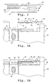
- Figs. 1A and 1B show an immunoassay cassette 10 constructed according to one embodiment of the invention.
- the cassette contains two platelike members, a base member or body 12 and a support or support member 14, which may be produced by standard molding or machining methods.
- the support is mounted on the body for movement in a vertical direction in the figures from an at-rest position seen in Fig. 1A to a sample-transfer position shown in Fig. 1B . More particularly, the support is mounted for movement toward and away from a sample transfer position.
- the structure mounting the support on the body may be compressible blocks, such as elastomeric blocks, as shown at 16, which support opposite ends of the support. These blocks become compressed as the support is moved from its at-rest position, where the blocks are substantially uncompressed, to the sample-transfer position, where the blocks are maximally compressed. It will be appreciated that a variety of compressible structures, such as springs or magnets, could be to mount the support on the cassette body for biased movement toward and away from the sample-transfer position.
- a sample well 18 for receiving the body fluid sample to be analyzed.
- the well is designed to receive a body-fluid sample, such as a blood or serum sample, typically having a volume between about 20 and about 60 ⁇ l.
- the sample well transfers sample to a center pad 20.
- the center pad communicates through a capillary wick 22, also referred to herein as a spreading layer, with a reagent pad or reservoir 24 containing a first reagent or reagent composition, to be described.
- a capillary wick 22 also referred to herein as a spreading layer
- reagent pad or reservoir 24 containing a first reagent or reagent composition
- one of more of the elements in the flow path between the sample well and the reservoir, and typically the center pad and/or the spreading layer, may be effective to remove or retard the flow of red blood cells, so that the sample material reaching the reservoir has been freed of blood cells or other particulate components.
- Glass fiber and other matrix material suitable for this purpose are well known.
- one or more of the elements in the flow path may be effective to remove undesired sample components through the use of immobilized binding agents, e.g. , antibodies, specific against the unwanted components.
- Undesired sample components can also be removed by exposing the sample to a precipitating agent in the flow path effective to selectively precipitate the undesired sample components.
- a precipitating agent for example, dextran sulfate may be used to selectively precipitate certain lipoproteins in a blood sample. The precipitated particles are either blocked from migration through the flow path, or retarded in flow.
- the center pad, sample transfer strip, and reservoir are preferably formed of bibulous, fibrous material capable of drawing fluid via capillary flow.
- a variety of fibrous materials such as are commonly used in fibrous-mat filters, including cellulose, cellulose acetate, and glass fibrous matrices, are suitable materials for the transfer strip.
- the fibers may be crosslinked, if desired, by chemical crosslinking, heat fusion, or the like.
- porous substrates such as sintered glass, fused polymer beads, and the like, whose wettability and dimension of interstices are such as to promote movement of an aqueous medium into the strip by surface wetting.
- One exemplary material is a glass fiber filter having a packing density of about 0.2 - 0.5 gm/cm 3 .
- the center glass, spreading layer and reservoir may be mounted on the body directly on the body or through a backing made of plastic or other inert support material.
- the cassette embodiment shown is designed for a single assay, at the right side of the cassette in the figures, it will be appreciated that the cassette could be adapted for additional assay(s) at the left side of the cassette.
- the additional assay may have the same fluid-flow format, or may have a different format, e.g. , the center pad may communicate with an elongate reaction strip extending along the upper left edge region of the cassette body.
- a pair of elastomeric blocks 26 on either side of the center pad serve to cushion and limit the movement of the support as it is moved toward its sample-transfer position.
- Support 14 has a pair of elongate reaction bars, such as bar 28, extending outwardly from the center of the support, as seen in Figs. 1A and 1B .
- An elongate reagent strip 30 is affixed to and extends along the lower, inward-facing surface of the support, as shown.
- the strip has an upstream sample-transfer zone 32 and a downstream detection zone 34 located directly below a window 36 formed in the support bar.
- FIG. 1B movement of the support to its sample-transfer position, with compression of blocks 16, brings the sample-transfer zone into contact with the reagent reservoir on the cassette body, promoting capillary fluid flow from the reservoir to the reagent strip.
- the reagent strip is formed of a material porous or fibrous material which promotes capillary flow therethrough.
- Preferred materials include porous, fused polymer or microporous polymer membranes, such as polysulfone, polypropylene, nylon, nitrocellulose, Teflon TM , or polyvinylchloride microporous membranes.
- nitrocellulose such as is available from Sartorius, is particularly preferred, with such having length, width, and thickness dimensions between 5-20 mm, 1-5 mm, and 0.1-0.5 mm, respectively.
- the downstream end of strip 30 is in contact with an absorbent pad 38 which functions as a reservoir to draw sample liquid supplied to the strip at the sample-transfer zone, and flowing in a downstream direction (to the right in the figures) into and through the detection zone.
- the pad is formed of a suitable absorbent material such as fibrous glass or cellulose.
- the absorbance volume of the pad is preferably at least half of the volume of the sample added, e.g. , 10 to 30 ⁇ l.
- reagents Disposed within the fluid pathway defined by the reagent strip are reagents, described further below, effective to produce a detectable, analyte-dependent reaction product which is detected at the detection zone.
- reagents described further below, effective to produce a detectable, analyte-dependent reaction product which is detected at the detection zone.
- Various assays may therefore be carried out using the cassette, as described below.
- the outer-facing surface of the reagent strip, downstream of the sample-transfer zone, is covered by an impermeable reflective film 39, such as a Mylar film.
- the film extends over the detection zone in the reagent strip, which is sandwiched between the support window and the reflective film.
- the purpose of the reflective strip is to enhance the reflectivity of the reagent strip, as viewed through the support window, and in particular, to enhance the change in reflectivity observed when the strip is wetted, and in response to an analyte-specific reaction occurring in the detection zone, as will be discussed further below.
- Fig. 2 The construction of the various layers on the support is illustrated in exploded view in Fig. 2 . Shown here are support bar 28 having window 36 located therein, and reagent strip 30 having upstream sample-transfer zone 32 and detection zone 34.
- the strip is attached to the support bar with a double-side adhesive strip 44 initially covered with a removable backing 45. As shown, the adhesive strip is separated by a space corresponding to the support window and detection zone.
- Absorbent pad 38 is positioned to overlap with the downstream end of reagent strip 30, and the reflective film is positioned to extend from a point just downstream of the sample-transfer region in strip 30 to a point beyond the absorbent pad.
- the components above are arranged as shown, and attached to the support bar and to one another by removing adhesive backing 44 and pressing the adhesive side of the assembly firmly against the support bar.
- the cassette is designed particularly for an analyte assay in which (i) sample components, which typically include the analyte itself, react with one or more reagents in the reservoir to form a modified sample, and (ii) the modified sample, typically modified analyte, reacts with a second reagent composition to produce a detectable, analyte-dependent product. That is, both the reagent reservoir and the reagent strip in this preferred embodiment contain one or more reagents for carrying out these reactions.
- the one or more reagents in the reservoir and strip are also referred to herein as a first and second reagent compositions, respectively, and may include one or more enzymes, antibodies, labeled antibodies, or enzyme substrates, binding agents, and/or precipitation agents, as discussed further below.
- the reagent composition in the reservoir includes a non-immobilized analyte-specific antibody labeled, e.g. , covalently with a detectable reporter, e.g. , metal particles, fluorescent or colored molecules, branched polymers containing attached colored or fluorescent moieties, and coated particles, e.g ., fluorescent-coated latex particles.
- a detectable reporter e.g. , metal particles, fluorescent or colored molecules, branched polymers containing attached colored or fluorescent moieties, and coated particles, e.g ., fluorescent-coated latex particles.
- non-immobilized is meant that the reagent is freely mobile within the reservoir.
- the reagent compositions may be immobilized or non-immobilized, depending on whether the reagent must comigrate with the analyte and/or whether the reagent would be expected to interfere with the final analyte determination.
- Methods of labeling a binding agent are known in the art, including the use of radiolabels, fluorescent labels, or linked enzymes which convert a separate substrate to a detectable species.
- a variety of reporter-labeled antibodies such as enzyme-labeled antibodies, are commercially available or may be readily prepared according to known methods (see, e.g ., Harlow, pp. 319-358).
- Optically detectable labeling methods are preferred for use with the present immunoassay cassette. Enzymes which react with a substrate to produce a visible reaction product are widely used for this purpose.
- a particularly preferred labeled reagent is an analyte-specific antibody conjugated to a visible particle such as a colored latex bead or colloidal gold. Such conjugates are described in U.S. Patent No. 4,313,734 (Leuvering) and may also be obtained from manufacturers such as BB International (Cardiff, UK) and NanoProbes (Stony Brook, NY).
- the reagent composition in the reagent strip which may include one or more reagents, may be distributed throughout the strip, or localized on the strip, for example, at the sample-transfer zone, just downstream of the transfer zone, or in the detection zone, in immobilized or non-immobilized form.
- the second reagent composition includes an anti-analyte antibody immobilized at the detection zone.
- labeled analyte-antibody complex transferred from the reservoir to the reagent strip migrates in a downstream direction in the strip, where it is captured in the detection zone.
- the step of forming a detectable reaction product includes capturing a detectable complex at the detection zone.
- the second reagent composition may include immobilized or non-immobilized enzymes, substrates, labeled binding reagents, photosensitizer agents, reducing or oxidizing agents, and/or acid or base groups that that can donate protein and hydroxyl ions as part of an analyte-detection reaction, according to known, two-step reaction procedures, where, in the present invention, one of the steps is to be carried out in the reagent reservoir, and the second in the reagent strip.
- the detection zone may contain reagents effective to produce a detectable reaction product with unlabeled antibody-analyte complex.
- the detection zone may contain an oxidase, a peroxidase, and a compound oxidizable to a detectable species such as a dye.
- the analyte-antibody complex includes a substrate for the oxidase
- the H 2 O 2 generated in the resulting reaction reacts with the oxidizable compound, catalyzed by the peroxidase, to generate the detectable dye.
- assays are described, for example, in Hewett et al.
- the reagents may be incorporated into the reservoir and strip by soaking the reservoir or strip material in a solution of the reagents, followed by drying, or adding a solution of the reagent material to the entire or a localized region of the strip, followed by drying.
- the reservoir or strip region may naturally provide, or be chemically modified according to known methods to have surface reactive groups, such as amine, carboxyl, sulfhydryl, or aldehyde groups, allowing covalent coupling by the use of activating agents or bifunctional coupling agents.
- the cassette is designed for detection of C-reactive protein, typically measured in a blood or serum sample.
- the reagent composition in the reservoir is a non-immobilized monoclonal antibody specific against a C-reactive protein epitope, i.e. , an epitope on one of the 5 identical subunits in C-reactive protein.
- a C-reactive protein epitope i.e. , an epitope on one of the 5 identical subunits in C-reactive protein.
- One exemplary anti-C-reactive protein antibody is a monoclonal antibody produced by cell line identified by clone number CC002, and available from Scripps Laboratories (San Diego, CA). The antibody is labeled by conjugation to gold microparticles, according standard methods, e.g.
- the second reagent is an antibody specific against C-reactive protein and immobilized at the detection zone.
- An exemplary antibody is the same as that employed in the first (reservoir) antibody reagent. Details of the assay are given in Example 1.
- Figs. 3A and 3B illustrate the flow of sample liquid into and through the fluid-flow elements of the cassette during cassette operation.
- liquid sample applied to sample well 18 is drawn by capillarity into center pad 20, and from here, through the spreading layer into reservoir 24.
- the sample may be held for a desired incubation time, in the presence of the first reagent. Typical incubation times may vary from a few seconds up to ten minutes or more.
- sample liquid flows by capillarity into the strip transfer zone when the latter is brought into contact with the reservoir. From the transfer zone, the sample liquid migrates in a downstream direction into and through the detection zone and ultimately into absorbent pad 38.
- the cassette can be operated to control the period of sample incubation before sample is first transferred from the reservoir to the reagent strip.
- the rate of liquid transfer, and the total sample volume transferred can be controlled by controlling (i) the cycle frequency with which the actuator moves the support toward and away from its transfer position, (ii) the time of contact that the support is held in its transfer position, during each cycle, and (iii) the total number of transfer cycles.
- this control is conveniently provided by a cassette-handling instrument in an assay apparatus constructed in accordance with another aspect of the invention.
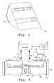
- Fig. 4 is a perspective view of a cassette-handling instrument 48 constructed in accordance with the invention
- Fig. 5 shows key functional elements of the instrument in diagrammatic form.
- the instrument includes a cassette holder, represented by arms 50, adapted to receive and hold the cassette in an operative condition when a sample liquid has been added to the cassette.
- arms 50 are biased to engage guide notches, such as notches 52, in the cassette body to anchor the cassette in the holder at a desired position.
- the instrument further includes an actuator 53 having solenoid-activated pistons or pushers, indicated at 54 operable to engage the cassette support and move the support from its relaxed-state to its sample-transfer position, upon actuation from a control unit 55 in the instrument.
- the control unit may be programmed or user-adjusted to control the one or more of the following actuator variables:
- control unit can be preprogrammed to control liquid transfer in the assay in an optimized manner for any selected type of assay chemistry.
- Various liquid transfer profiles that can be achieved with the invention will be considered below.
- the cassette-handling instrument includes a photo-detector 56, operable to detect changes in the reflectance of the detection zone, as observed through window 36.
- the photo-detector in this case may be a simple device for measuring the light intensity of reflectance at the window, when the detection window is illuminated by a light source, e.g ., an LED, also forming part of the detector.
- the detector may include a selected-wavelength fluorescence excitation beam and emitted-light detector, or a selected-wavelength visible light source and photo-detector for measuring light absorption at the detection surface.
- the reflective film is effective to enhance, i.e ., amplify the reflectance intensity, and thus improve resolution and accuracy.
- the enhanced reflectance also allows the detection zone to serve as a "control" to monitor fluid flow through the reagent strip.
- one feature is the ability to control the rate and volume of fluid flow from one reaction area to another, and thus the kinetics of the reactions and the total assay volume. This feature is important where one or more of the assay reactions are rate-limiting or where it is desired to assay a kinetic end point. The feature is also important in controlling the total amount of sample liquid that flows into and through the detection zone, for quantitating the concentration of analyte in the zone.
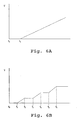
- Figs. 6A and 6B illustrate two sample transfer curves that illustrate the different sample transfer characteristics that can be achieved in the invention.
- sample is added to the cassette at time t 0 , and allowed to incubate in the reagent reservoir until a time t 1 , when the support bar in the cassette is brought into contact with the reservoir. If the support bar is held in contact with the reservoir over an extended period, sample transfer into the strip, expressed as sample volume as a function of time, increases linearly until a time t f when both strip and pad are fully saturated (ignoring sample evaporative effects).
- Fig. 6B the sample incubation time, from t 0 to t 1 , is the same as in Fig. 6A , but sample transfer is effected by three discrete transfer events, interspersed with intervals in which the support is move out of contact with the reservoir and volume accumulation over time is flat.
- the latter approach allows a more controlled, and typically slower rate of volume transfer than when sample transfer occurs as an unbroken event.
- Fig. 7 shows an exemplary reflectance curve for an assay in which C-reactive protein analyte reacts first with labeled anti-analyte antibody in the cassette reservoir, to form a detectable analyte-antibody complex, and the complex is then transferred to the reagent strip, where it is captured by an immobilized anti-analyte antibody in the detection zone.
- the initial reflectance in the first few seconds after sample transfer to the support, corresponds to a dry strip reflectance.
- the precipitous drop in reflectance occurs when the leading edge of the transferred sample passes through the detection zone.
- the drop in reflectance is due both to the wetting of the strip in the detection zone and the presence of colloidal gold labeled antibodies, either in complexes or non-complexed form.
- the level of reflectance begins to change over time, depending on the relative concentrations of complexed and non-complexed antibody conjugate, i.e., depending on the sample analyte concentration.
- the reflectance begins to increase over time as more and more of the conjugate is carried out of the detection zone by sample transfer through the zone. This is seen in the "diamond" plot in Fig. 7 .
- progressively more conjugate is captured in the detection zone, with sample flow through the zone, acting to decrease reflectance over time, as indicated for the "triangle" plot in the same figure.
- the analyte concentration is measured by comparing the measured reflectance at a selected end point, e.g ., 4 minutes, with standard reflectance measurements from known analyte concentrations.
- the measured reflectance may be expressed, for example, as a ratio of the final percent reflectance to initial percent reflectance. As seen in the plot shown in Fig. 8 , a plot of this ratio shows an analyte-dependent curve over a C-reactive protein concentration of 0 to 8 ⁇ g/ml.
- the cassette provides a dry-strip assay format in which successive analyte-dependent reactions can be carried out in a controlled manner, by controlling volume and rate transfer from one reaction region to another.
- the cassette is designed to allow controlled and measured volumes of sample through the detection zone, for more quantitative determination of analyte concentration.
- the cassette format is amenable to multiple assays in the same cassette, and fed from the same sample.
- the reflector strip in the support bar acts to enhance reflectance changes, enhancing the reliability and resolution of an assay.
- the cassette of the invention is supplied with solutions and reagents preloaded and is thus entirely self-contained, not requiring operator loading of solutions.
- the reader containing the cassette may be programmed to adjust the cassette to its different operational positions at designated times.
- a multiple-stage assay may thus be carried out with the cassette contained within a cassette reader, requiring no outside operator input.
- a blood sample was analyzed for levels of C-reactive protein. Altered levels of this compound have been shown to be diagnostic of disorders characterized by risk factors for cerebral vascular ischemia and stroke, and ischemic heart disease and stroke (see, for example, De Maat, Grau, Kuller, Liuzzo, Mendall, Thompson, and Tracy).
- the cassette for the assay was prepared as follows:
- the center pad was a glass fiber pad capable of absorbing about 20 ⁇ l of liquid.
- the spreading layer was also glass fiber.
- the reservoir was a porous plastic material having a total absorption volume of about 6 ⁇ l.
- the reservoir was initially soaked with 6 ⁇ l of a 20 O.D. solution of antibody conjugate formed by conjugating colloidal gold with antibody specific against C-reactive protein, obtained from BBlnternational (Cardiff, UK). The reservoir was then dried.
- the reagent strip in the cassette was an 11 mm by 3 mm nitrocellulose strip, obtained from Sartorius (Goettingen, GmbH), having a thickness of less than 10 mils (0.25 mm).
- the antibody against C-reactive protein was attached to the detection region through hydrophobic interaction with the nitrocellulose.
- the detection region was located about 6 mm from the sample-transfer region.
- the absorption pad at the downstream end of the strip was a cellulose fiber material, having a total absorption volume of about 25 ⁇ l.
- a 50 ⁇ l human blood sample was applied to the sample well in the cassette. After an incubation period of 3 minutes, the support was moved to its sample-transfer position for 4 minutes. During flow of sample liquid onto the strip, the reflectance at the support-bar window was monitored. At about 4 minutes, a stable end point was reached ( Fig. 8 ). The signal ratio of end-point reflectance to initial reflectance was determined and used to calculate analyte concentration from a standard curve generated by samples with known amounts of C-reactive protein.
- a cassette is prepared substantially as described in Example 1.
- the cassette is removably placed in a cassette holder during the sample assay.
- the cassette is moved toward and away from the sample-transfer position by an actuator to effect incubation of the reagents.
- the analyte-specific reaction in the detection zone of the reagent strip is detected by a detector.
- the volume and rate of sample transfer from said reagent reservoir to the reagent strip during the assay procedure is controlled by a control unit connected to the actuator.
- a body fluid suspected of containing the analyte of interest is introduced into an absorbent reservoir containing a reagent composition effective to react with one or more sample components to form a modified sample.
- the absorbent reservoir containing the absorbed body-fluid sample is repeatedly contacted with a reagent strip containing a second reagent composition effective to react with the modified sample formed in the reservoir to produce a detectable analyte-dependent product.
- the frequency and duration of the repeated contact are controlled to control the volume and rate of transfer of sample fluid from the reservoir to the reagent strip.
- the analyte-dependent product is detected by any known means.
Abstract
Description
- The present invention is directed to a cassette, apparatus and method for use in assaying a body fluid sample for a selected analyte, and particularly for use in automated multi-stage assays.
-
- De Maat, M.P.M. et al., Fibrinolysis 8(Suppl 2):50-52 (1994).
- Grau, A.J. et al., "Clinical and Biochemical Analysis in Infection-Associated Stroke." Stroke 26(9):1520-1526 (1995).
- Harlow, E. et al., "Antibodies: A Laboratory Manual", Cold Spring Harbor Lab (1988).
-
Hewett, G.E., U.S. Patent No. 5,110,724 (1992 ). -
Hewett, G.E. et al., U.S. Patent No. 5,171,688 (1992 ). - Kuller, L.H. et al., Am J Epidemiol. 144:537-5547 (1996).
-
Leuvering et al., U.S. Patent No. 4,313,734 (1982 ). - Liuzzo G, M.D. et al., N Engl J Med 331(7):417-424 (1994).
- Mendall, M.A. et al., British Med. J. 312:1061-1065 (1996).
- Thompson, S.G. et al., N Engl J Med 332:635-641 (1995).
- Tracy, R.P. et al., Circulation, 93(3):8 (1996).
-
WO 00/42 434 WO 98/37 416 EP-A2-0 249 851 . - Assays for detecting the presence and level of a variety of analytes in body fluid samples are known. Such assays are often designed for simplicity of use so that they can be reliably conducted in a doctors office or other clinical setting where personnel may have little training in clinical assay procedure or in interpreting assay results. In order to minimize the need for operator involvement, it is preferable that the assay be carried out in an automated or self-contained manner.
- Such self-contained assays have typically been limited, for the sake of simplicity of operation, to one-step assay procedures. A number of useful assays, however, are multistage in nature, requiring more than one reacting or binding step. Further, one or more of the steps may be rate limiting, or affected by localized reagent concentrations. Typically, multistage assays are less readily automated and generally require more input from the user, thus increasing the possibility of error.
- The
WO 00/42434 - The
WO 98/37416 - The
EP-A2-0 249 851 discloses a multizone test device which may comprise a reflective layer. - It is therefore desirable to provide an automated, self-contained assay device which is able to perform multistage assays, in particular those containing multiple reacting or binding steps in which one or more of the steps is rate limiting or the final assay result is affected by localized reagent of analyte concentrations.
- In one aspect, the invention includes an immunoassay cassette for use in detecting an analyte in a liquid body-fluid sample is disclosed. The cassette provides a cassette body having a sample well for receiving the sample, a support mounted on the body, for movement toward and away from a transfer position, and a reagent reservoir and a reagent strip carried on the body and support, respectively. The reagent reservoir contains a first reagent composition effective to react with one or more sample components to form a modified sample, as sample migrates from the sample well into the reservoir. The reagent strip contains a second reagent composition effective to react with the modified sample to form a detectable analyte-dependent product. The reagent strip has a transfer zone that is brought into contact with the reservoir, when the support is moved to its transfer position, and a detection zone located downstream of the transfer zone. By controlling the movement of the support toward and away from its transfer position, the volume and rate of sample flow from the reservoir to the strip can be controlled to optimize and/or standardize sample-transfer conditions in the assay.
- For use in detecting a multivalent analyte in a liquid body-fluid sample, the first reagent composition in the reagent reservoir may include a non-immobilized conjugate of an anti-analyte antibody and a detectable reporter group, where the reaction to form a modified sample includes binding of the conjugate to sample analyte, to form an analyte-conjugate complex. The second reagent composition in the reagent strip may include an anti-analyte antibody immobilized at a detection region in the reagent strip located downstream of the strip's sample-transfer region, where the reaction to form a detectable analyte-dependent product includes binding of complex to the immobilized antibody, to localize the detectable reporter in the complex at the detection zone. The nonimmobilized conjugate in this embodiment may be a conjugate of an anti-analyte-antibody and a visible reporter, such as metal particles, particles labeled with colored or fluorescent moieties, polymers labeled with colored or fluorescent moieties, particles, or colored or fluorescent molecules.
- For use in detecting C-reactive protein analyte in a blood sample, the anti-analyte antibody in the non-immobilized conjugate in the reagent reservoir, and the immobilized anti-analyte antibody in the reagent strip may be antibodies specific against a common epitope in C-reactive protein. Alternatively, the two antibodies may be directed against different C-reactive protein epitopes.
- The support includes a window through which binding of the complex at the detection zone in the reagent strip can be viewed. In addition, the detection zone in the reagent strip is covered by a reflective film at the strip surface facing away from the window.
- The cassette may further include an absorbent reservoir carried on the support, downstream of said detection zone, for receiving sample liquid transferred through the reagent strip.
- In another aspect, the invention includes apparatus for use in detecting an analyte in a liquid body-fluid sample. The apparatus includes a cassette of the type described above, and a cassette-handling instrument. The instrument has (a) a cassette holder into which the cassette is removably placed, during a sample assay, (b) an actuator operable to move the support in the cassette toward and away from its sample-transfer position, (c) a detector operable to detect an analyte-specific reaction at the detection zone in the reagent strip, and (d) a processor operably connected to the actuator, for controlling the volume timing and rate of movement of sample material from the reagent reservoir to the reagent strip.
- The detection zone in the reagent strip in the cassette is covered by a reflective film at the strip's surface facing away from said window, such that flow of sample liquid through the detection zone produces a first change in reflectance measurable through the window, and the presence of analyte-dependent reaction at the detection zone produces a second change in reflectance measurable through the window. The detector may be operable to detect liquid flow through the detection zone, by a first change in measured optical reflectance, and is operable to measure a subsequent analyte-dependent reaction at the detection zone, by a second change in measured optical reflectance.
- The control unit may be operable to control the volume and rate of sample transfer from the reagent reservoir to the reagent strip by controlling one or more of (i) the cycle frequency with which the actuator moves the support toward and away from its transfer position, (ii) the time of contact that the support is held in its transfer position, during each cycle, and (iii) the total number of transfer cycles. Preferably, the unit is operable to control the volume and rate of sample transfer from said reservoir to the reagent strip by controlling (i) the cycle frequency with which the actuator moves the support toward and away from its transfer position and (ii) the time of contact that the support is held in its transfer position, during each cycle.
- In still another aspect, the invention includes a method of conducting an assay for a body-fluid analyte, by the steps of: (a) introducing a body fluid containing the analyte into a absorbent reservoir containing a first reagent composition effective to react with one or more sample components to form a modified sample, (b) repeatedly contacting the reservoir, with such containing an absorbed body-fluid sample, with an absorbent reagent pad containing a second reagent composition effective to react with the modified sample formed in the reservoir to produce a detectable analyte-dependent product, and (c)controlling the frequency and duration of said contacting, thereby to control the volume and rate of transfer of sample fluid from the reservoir to the pad.
- In one general embodiment, the reagent pad is an elongate reagent strip having a sample-transfer zone at which the reservoir makes contact with the strip, and a detection zone located downstream of the transfer zone.
- For detecting a multivalent analyte in a liquid body-fluid sample, such as C-reactive protein in a blood or serum sample, the first reagent composition in the reagent reservoir may include a non-immobilized conjugate of an anti-analyte antibody and a detectable reporter group, and the reagent composition in the reagent strip, an anti-analyte antibody immobilized at a detection region in the reagent strip.
- These and other objects and features of the invention will become more fully apparent when the following detailed description of the invention is read in conjunction with the accompanying drawings.
-
-
Figs. 1A and 1B are plan views of an immunoassay cassette constructed in accordance with one embodiment of the invention, with the cassette in an initial sample loading position (Fig. 1A ), and a sample-transfer position (Fig. 1B ); -
Fig. 2 is an enlarged section view of the cassette support in the region of the detection zone; -
Figs. 3A and 3B illustrate the distribution of sample fluid prior to (Fig. 3A ), and following (Fig. 3B ) sample-fluid transfer in the cassette; -
Fig. 4 is a perspective view of a cassette-handling instrument constructed according to one embodiment of the invention; -
Fig. 5 illustrates various functional components of the cassette-handling instrument in relationship to an immunoassay cassette of the invention; -
Figs. 6A and 6B illustrate different sample-volume transfer profiles achievable by the invention; -
Fig. 7 illustrates reflectance profiles for a C-reactive protein analyte at three different concentrations, during an assay procedure in accordance with one embodiment of the invention; and -
Fig. 8 is a plot of measured reflectance as a function of C-reactive protein analyte concentration, generated in accordance with.the invention. - For convenience, similar element numbering is retained in all the figures to identify like structural features.
-
Figs. 1A and 1B show animmunoassay cassette 10 constructed according to one embodiment of the invention. The cassette contains two platelike members, a base member orbody 12 and a support orsupport member 14, which may be produced by standard molding or machining methods. The support is mounted on the body for movement in a vertical direction in the figures from an at-rest position seen inFig. 1A to a sample-transfer position shown inFig. 1B . More particularly, the support is mounted for movement toward and away from a sample transfer position. - The structure mounting the support on the body may be compressible blocks, such as elastomeric blocks, as shown at 16, which support opposite ends of the support. These blocks become compressed as the support is moved from its at-rest position, where the blocks are substantially uncompressed, to the sample-transfer position, where the blocks are maximally compressed. It will be appreciated that a variety of compressible structures, such as springs or magnets, could be to mount the support on the cassette body for biased movement toward and away from the sample-transfer position.
- Provided within
body 12 is a sample well 18 for receiving the body fluid sample to be analyzed. The well is designed to receive a body-fluid sample, such as a blood or serum sample, typically having a volume between about 20 and about 60 µl. The sample well transfers sample to acenter pad 20. The center pad, in turn, communicates through acapillary wick 22, also referred to herein as a spreading layer, with a reagent pad orreservoir 24 containing a first reagent or reagent composition, to be described. When sample liquid is placed in well 18, it migrates by capillarity through the center pad, and from the center pad, through the spreading layer to thereservoir 24. Where the sample being analyzed is a blood sample, one of more of the elements in the flow path between the sample well and the reservoir, and typically the center pad and/or the spreading layer, may be effective to remove or retard the flow of red blood cells, so that the sample material reaching the reservoir has been freed of blood cells or other particulate components. Glass fiber and other matrix material suitable for this purpose are well known. - Alternatively, or in addition, one or more of the elements in the flow path may be effective to remove undesired sample components through the use of immobilized binding agents, e.g., antibodies, specific against the unwanted components. Undesired sample components can also be removed by exposing the sample to a precipitating agent in the flow path effective to selectively precipitate the undesired sample components. For example, dextran sulfate may be used to selectively precipitate certain lipoproteins in a blood sample. The precipitated particles are either blocked from migration through the flow path, or retarded in flow. The center pad, sample transfer strip, and reservoir are preferably formed of bibulous, fibrous material capable of drawing fluid via capillary flow. A variety of fibrous materials, such as are commonly used in fibrous-mat filters, including cellulose, cellulose acetate, and glass fibrous matrices, are suitable materials for the transfer strip. The fibers may be crosslinked, if desired, by chemical crosslinking, heat fusion, or the like. Also suitable are porous substrates, such as sintered glass, fused polymer beads, and the like, whose wettability and dimension of interstices are such as to promote movement of an aqueous medium into the strip by surface wetting. One exemplary material is a glass fiber filter having a packing density of about 0.2 - 0.5 gm/cm3. The center glass, spreading layer and reservoir may be mounted on the body directly on the body or through a backing made of plastic or other inert support material.
- Although the cassette embodiment shown is designed for a single assay, at the right side of the cassette in the figures, it will be appreciated that the cassette could be adapted for additional assay(s) at the left side of the cassette. Further, the additional assay may have the same fluid-flow format, or may have a different format, e.g., the center pad may communicate with an elongate reaction strip extending along the upper left edge region of the cassette body.
- Completing the description of the cassette body, a pair of
elastomeric blocks 26 on either side of the center pad serve to cushion and limit the movement of the support as it is moved toward its sample-transfer position. -
Support 14 has a pair of elongate reaction bars, such asbar 28, extending outwardly from the center of the support, as seen inFigs. 1A and 1B . Anelongate reagent strip 30 is affixed to and extends along the lower, inward-facing surface of the support, as shown. The strip has an upstream sample-transfer zone 32 and adownstream detection zone 34 located directly below awindow 36 formed in the support bar. As seen inFig. 1B , movement of the support to its sample-transfer position, with compression ofblocks 16, brings the sample-transfer zone into contact with the reagent reservoir on the cassette body, promoting capillary fluid flow from the reservoir to the reagent strip. - The reagent strip is formed of a material porous or fibrous material which promotes capillary flow therethrough. Preferred materials include porous, fused polymer or microporous polymer membranes, such as polysulfone, polypropylene, nylon, nitrocellulose, Teflon™, or polyvinylchloride microporous membranes. In the present case, nitrocellulose, such as is available from Sartorius, is particularly preferred, with such having length, width, and thickness dimensions between 5-20 mm, 1-5 mm, and 0.1-0.5 mm, respectively.
- The downstream end of
strip 30 is in contact with anabsorbent pad 38 which functions as a reservoir to draw sample liquid supplied to the strip at the sample-transfer zone, and flowing in a downstream direction (to the right in the figures) into and through the detection zone. The pad is formed of a suitable absorbent material such as fibrous glass or cellulose. The absorbance volume of the pad is preferably at least half of the volume of the sample added, e.g., 10 to 30 µl. - Disposed within the fluid pathway defined by the reagent strip are reagents, described further below, effective to produce a detectable, analyte-dependent reaction product which is detected at the detection zone. Various assays may therefore be carried out using the cassette, as described below.
- The outer-facing surface of the reagent strip, downstream of the sample-transfer zone, is covered by an impermeable
reflective film 39, such as a Mylar film. In particular, the film extends over the detection zone in the reagent strip, which is sandwiched between the support window and the reflective film. The purpose of the reflective strip is to enhance the reflectivity of the reagent strip, as viewed through the support window, and in particular, to enhance the change in reflectivity observed when the strip is wetted, and in response to an analyte-specific reaction occurring in the detection zone, as will be discussed further below. - The construction of the various layers on the support is illustrated in exploded view in
Fig. 2 . Shown here aresupport bar 28 havingwindow 36 located therein, andreagent strip 30 having upstream sample-transfer zone 32 anddetection zone 34. The strip is attached to the support bar with a double-sideadhesive strip 44 initially covered with aremovable backing 45. As shown, the adhesive strip is separated by a space corresponding to the support window and detection zone.Absorbent pad 38 is positioned to overlap with the downstream end ofreagent strip 30, and the reflective film is positioned to extend from a point just downstream of the sample-transfer region instrip 30 to a point beyond the absorbent pad. In construction, the components above are arranged as shown, and attached to the support bar and to one another by removingadhesive backing 44 and pressing the adhesive side of the assembly firmly against the support bar. - The cassette is designed particularly for an analyte assay in which (i) sample components, which typically include the analyte itself, react with one or more reagents in the reservoir to form a modified sample, and (ii) the modified sample, typically modified analyte, reacts with a second reagent composition to produce a detectable, analyte-dependent product. That is, both the reagent reservoir and the reagent strip in this preferred embodiment contain one or more reagents for carrying out these reactions. The one or more reagents in the reservoir and strip are also referred to herein as a first and second reagent compositions, respectively, and may include one or more enzymes, antibodies, labeled antibodies, or enzyme substrates, binding agents, and/or precipitation agents, as discussed further below.
- In one exemplary cassette, for detection of a multi-valent antigen analyte, the reagent composition in the reservoir includes a non-immobilized analyte-specific antibody labeled, e.g., covalently with a detectable reporter, e.g., metal particles, fluorescent or colored molecules, branched polymers containing attached colored or fluorescent moieties, and coated particles, e.g., fluorescent-coated latex particles. By "non-immobilized" is meant that the reagent is freely mobile within the reservoir. Thus, when analyte is added to the reservoir, it reacts specifically with the antibody reagent to form a mobile, labeled analyte-antibody complex. In other embodiments, the reagent compositions may be immobilized or non-immobilized, depending on whether the reagent must comigrate with the analyte and/or whether the reagent would be expected to interfere with the final analyte determination.
- Methods of labeling a binding agent, such as labeled antibodies, are known in the art, including the use of radiolabels, fluorescent labels, or linked enzymes which convert a separate substrate to a detectable species. A variety of reporter-labeled antibodies, such as enzyme-labeled antibodies, are commercially available or may be readily prepared according to known methods (see, e.g., Harlow, pp. 319-358). Optically detectable labeling methods are preferred for use with the present immunoassay cassette. Enzymes which react with a substrate to produce a visible reaction product are widely used for this purpose. A particularly preferred labeled reagent is an analyte-specific antibody conjugated to a visible particle such as a colored latex bead or colloidal gold. Such conjugates are described in
U.S. Patent No. 4,313,734 (Leuvering) and may also be obtained from manufacturers such as BB International (Cardiff, UK) and NanoProbes (Stony Brook, NY). - The reagent composition in the reagent strip, which may include one or more reagents, may be distributed throughout the strip, or localized on the strip, for example, at the sample-transfer zone, just downstream of the transfer zone, or in the detection zone, in immobilized or non-immobilized form. In the embodiment described above, for detection of a multivalent analyte, the second reagent composition includes an anti-analyte antibody immobilized at the detection zone. In this format, labeled analyte-antibody complex transferred from the reservoir to the reagent strip migrates in a downstream direction in the strip, where it is captured in the detection zone. The step of forming a detectable reaction product includes capturing a detectable complex at the detection zone.
- In other embodiments, the second reagent composition may include immobilized or non-immobilized enzymes, substrates, labeled binding reagents, photosensitizer agents, reducing or oxidizing agents, and/or acid or base groups that that can donate protein and hydroxyl ions as part of an analyte-detection reaction, according to known, two-step reaction procedures, where, in the present invention, one of the steps is to be carried out in the reagent reservoir, and the second in the reagent strip.
- More specifically, the detection zone may contain reagents effective to produce a detectable reaction product with unlabeled antibody-analyte complex. For example, the detection zone may contain an oxidase, a peroxidase, and a compound oxidizable to a detectable species such as a dye. When the analyte-antibody complex includes a substrate for the oxidase, the H2O2 generated in the resulting reaction reacts with the oxidizable compound, catalyzed by the peroxidase, to generate the detectable dye. Such assays are described, for example, in Hewett et al.
- The reagents may be incorporated into the reservoir and strip by soaking the reservoir or strip material in a solution of the reagents, followed by drying, or adding a solution of the reagent material to the entire or a localized region of the strip, followed by drying. Where the reagent is immobilized, the reservoir or strip region may naturally provide, or be chemically modified according to known methods to have surface reactive groups, such as amine, carboxyl, sulfhydryl, or aldehyde groups, allowing covalent coupling by the use of activating agents or bifunctional coupling agents.
- In one particular embodiment, the cassette is designed for detection of C-reactive protein, typically measured in a blood or serum sample. In this embodiment, the reagent composition in the reservoir is a non-immobilized monoclonal antibody specific against a C-reactive protein epitope, i.e., an epitope on one of the 5 identical subunits in C-reactive protein. One exemplary anti-C-reactive protein antibody is a monoclonal antibody produced by cell line identified by clone number CC002, and available from Scripps Laboratories (San Diego, CA). The antibody is labeled by conjugation to gold microparticles, according standard methods, e.g., as described in, Chandler, et al., The place of gold in rapid tests, IVD Technology, 6(2)37-49 (2000). The second reagent is an antibody specific against C-reactive protein and immobilized at the detection zone. An exemplary antibody is the same as that employed in the first (reservoir) antibody reagent. Details of the assay are given in Example 1.
-
Figs. 3A and 3B illustrate the flow of sample liquid into and through the fluid-flow elements of the cassette during cassette operation. As seen inFig. 3A , liquid sample applied to sample well 18 is drawn by capillarity intocenter pad 20, and from here, through the spreading layer intoreservoir 24. Here the sample may be held for a desired incubation time, in the presence of the first reagent. Typical incubation times may vary from a few seconds up to ten minutes or more. - When the support in the cassette is moved to its sample-transfer position, shown in
Fig. 3B , sample liquid flows by capillarity into the strip transfer zone when the latter is brought into contact with the reservoir. From the transfer zone, the sample liquid migrates in a downstream direction into and through the detection zone and ultimately intoabsorbent pad 38. By controlling the delay between addition of sample material to the cassette sample well and initial movement of the support to its sample-transfer position, the cassette can be operated to control the period of sample incubation before sample is first transferred from the reservoir to the reagent strip. - In addition the rate of liquid transfer, and the total sample volume transferred can be controlled by controlling (i) the cycle frequency with which the actuator moves the support toward and away from its transfer position, (ii) the time of contact that the support is held in its transfer position, during each cycle, and (iii) the total number of transfer cycles. As discussed in the next section, this control is conveniently provided by a cassette-handling instrument in an assay apparatus constructed in accordance with another aspect of the invention.
-
Fig. 4 is a perspective view of a cassette-handlinginstrument 48 constructed in accordance with the invention, andFig. 5 shows key functional elements of the instrument in diagrammatic form. The instrument includes a cassette holder, represented byarms 50, adapted to receive and hold the cassette in an operative condition when a sample liquid has been added to the cassette. In particular,arms 50 are biased to engage guide notches, such asnotches 52, in the cassette body to anchor the cassette in the holder at a desired position. - The instrument further includes an
actuator 53 having solenoid-activated pistons or pushers, indicated at 54 operable to engage the cassette support and move the support from its relaxed-state to its sample-transfer position, upon actuation from acontrol unit 55 in the instrument. In particular, the control unit may be programmed or user-adjusted to control the one or more of the following actuator variables: - (i) the period between sample addition to the cassette sample transfer to the strip. This time corresponds roughly to the incubation period of sample liquid exposure to and reaction with the first reagent composition, and may vary from several seconds up to 10 minutes or longer, depending on the nature of the first sample reaction.
- (ii) the cycle frequency with which the actuator moves the support toward and away from its transfer position. The frequency may be varied between one per assay, to a few per minute to one per second.
- (iii) the time of contact that the support is held in its transfer position, during each cycle. Together with frequency, this variable determines the total rate at which sample fluid is transferred to the reagent strip. This rate can be optimized for different types of assay chemistries. For example, it may be desirable to regulate the flow of material from the sample well through the reagent reservoir, to ensure sufficient reaction time in the reagent reservoir, or to meter the flow rate through the reagent strip, to ensure adequate reaction time in the strip.
- (iv) the total number of transfer cycles, which, together with contact time in each cycle, will determine the total volume transferred from the cassette body to the strip. By controlling the total volume transferred, a more quantitative measure of analyte concentration, expressed as amount of analyte/volume of sample can be determined. In particular, the volume that passes through the detection zone will be the total amount transferred less a predetermined quantity remaining in the portion of the strip upstream of the detection zone.
- It will be appreciated that the control unit can be preprogrammed to control liquid transfer in the assay in an optimized manner for any selected type of assay chemistry. Various liquid transfer profiles that can be achieved with the invention will be considered below.
- Also as shown in
Fig. 5 , the cassette-handling instrument includes a photo-detector 56, operable to detect changes in the reflectance of the detection zone, as observed throughwindow 36. The photo-detector in this case may be a simple device for measuring the light intensity of reflectance at the window, when the detection window is illuminated by a light source, e.g., an LED, also forming part of the detector. In other embodiments, the detector may include a selected-wavelength fluorescence excitation beam and emitted-light detector, or a selected-wavelength visible light source and photo-detector for measuring light absorption at the detection surface. - Particularly where the light detector is designed to measure reflectance from the reagent strip surface in the detection zone, the reflective film is effective to enhance, i.e., amplify the reflectance intensity, and thus improve resolution and accuracy. As will be seen in the next section, the enhanced reflectance also allows the detection zone to serve as a "control" to monitor fluid flow through the reagent strip.
- As noted above, one feature is the ability to control the rate and volume of fluid flow from one reaction area to another, and thus the kinetics of the reactions and the total assay volume. This feature is important where one or more of the assay reactions are rate-limiting or where it is desired to assay a kinetic end point. The feature is also important in controlling the total amount of sample liquid that flows into and through the detection zone, for quantitating the concentration of analyte in the zone.
-
Figs. 6A and 6B illustrate two sample transfer curves that illustrate the different sample transfer characteristics that can be achieved in the invention. In the first case, illustrated inFig. 6A , sample is added to the cassette at time t0, and allowed to incubate in the reagent reservoir until a time t1, when the support bar in the cassette is brought into contact with the reservoir. If the support bar is held in contact with the reservoir over an extended period, sample transfer into the strip, expressed as sample volume as a function of time, increases linearly until a time tf when both strip and pad are fully saturated (ignoring sample evaporative effects). - In
Fig. 6B , the sample incubation time, from t0 to t1, is the same as inFig. 6A , but sample transfer is effected by three discrete transfer events, interspersed with intervals in which the support is move out of contact with the reservoir and volume accumulation over time is flat. As can be appreciated, the latter approach allows a more controlled, and typically slower rate of volume transfer than when sample transfer occurs as an unbroken event. -
Fig. 7 shows an exemplary reflectance curve for an assay in which C-reactive protein analyte reacts first with labeled anti-analyte antibody in the cassette reservoir, to form a detectable analyte-antibody complex, and the complex is then transferred to the reagent strip, where it is captured by an immobilized anti-analyte antibody in the detection zone. The initial reflectance, in the first few seconds after sample transfer to the support, corresponds to a dry strip reflectance. The precipitous drop in reflectance occurs when the leading edge of the transferred sample passes through the detection zone. The drop in reflectance is due both to the wetting of the strip in the detection zone and the presence of colloidal gold labeled antibodies, either in complexes or non-complexed form. - With continued flow of sample material through the detection zone, the level of reflectance begins to change over time, depending on the relative concentrations of complexed and non-complexed antibody conjugate, i.e., depending on the sample analyte concentration. At lower analyte concentration, where relatively more of the conjugate is in non-complexed form, and relatively less of the conjugate is captured at the detection zone, the reflectance begins to increase over time as more and more of the conjugate is carried out of the detection zone by sample transfer through the zone. This is seen in the "diamond" plot in
Fig. 7 . Conversely, at higher analyte concentrations, progressively more conjugate is captured in the detection zone, with sample flow through the zone, acting to decrease reflectance over time, as indicated for the "triangle" plot in the same figure. - The analyte concentration is measured by comparing the measured reflectance at a selected end point, e.g., 4 minutes, with standard reflectance measurements from known analyte concentrations. The measured reflectance may be expressed, for example, as a ratio of the final percent reflectance to initial percent reflectance. As seen in the plot shown in
Fig. 8 , a plot of this ratio shows an analyte-dependent curve over a C-reactive protein concentration of 0 to 8 µg/ml. - From the foregoing, it can be appreciated how various objects and features of the invention are achieved. The cassette provides a dry-strip assay format in which successive analyte-dependent reactions can be carried out in a controlled manner, by controlling volume and rate transfer from one reaction region to another. In addition, the cassette is designed to allow controlled and measured volumes of sample through the detection zone, for more quantitative determination of analyte concentration. The cassette format is amenable to multiple assays in the same cassette, and fed from the same sample. Finally, the reflector strip in the support bar acts to enhance reflectance changes, enhancing the reliability and resolution of an assay.
- Preferably, the cassette of the invention is supplied with solutions and reagents preloaded and is thus entirely self-contained, not requiring operator loading of solutions. The reader containing the cassette may be programmed to adjust the cassette to its different operational positions at designated times. A multiple-stage assay may thus be carried out with the cassette contained within a cassette reader, requiring no outside operator input.
- In a specific application of the present device, a blood sample was analyzed for levels of C-reactive protein. Altered levels of this compound have been shown to be diagnostic of disorders characterized by risk factors for cerebral vascular ischemia and stroke, and ischemic heart disease and stroke (see, for example, De Maat, Grau, Kuller, Liuzzo, Mendall, Thompson, and Tracy).
- The cassette for the assay was prepared as follows: The center pad was a glass fiber pad capable of absorbing about 20 µl of liquid. The spreading layer was also glass fiber. The reservoir was a porous plastic material having a total absorption volume of about 6 µl. The reservoir was initially soaked with 6 µl of a 20 O.D. solution of antibody conjugate formed by conjugating colloidal gold with antibody specific against C-reactive protein, obtained from BBlnternational (Cardiff, UK). The reservoir was then dried.
- The reagent strip in the cassette was an 11 mm by 3 mm nitrocellulose strip, obtained from Sartorius (Goettingen, GmbH), having a thickness of less than 10 mils (0.25 mm). The antibody against C-reactive protein was attached to the detection region through hydrophobic interaction with the nitrocellulose. The detection region was located about 6 mm from the sample-transfer region. The absorption pad at the downstream end of the strip was a cellulose fiber material, having a total absorption volume of about 25 µl.
- In the assay method, a 50 µl human blood sample was applied to the sample well in the cassette. After an incubation period of 3 minutes, the support was moved to its sample-transfer position for 4 minutes. During flow of sample liquid onto the strip, the reflectance at the support-bar window was monitored. At about 4 minutes, a stable end point was reached (
Fig. 8 ). The signal ratio of end-point reflectance to initial reflectance was determined and used to calculate analyte concentration from a standard curve generated by samples with known amounts of C-reactive protein. - A cassette is prepared substantially as described in Example 1. The cassette is removably placed in a cassette holder during the sample assay. The cassette is moved toward and away from the sample-transfer position by an actuator to effect incubation of the reagents. The analyte-specific reaction in the detection zone of the reagent strip is detected by a detector. The volume and rate of sample transfer from said reagent reservoir to the reagent strip during the assay procedure is controlled by a control unit connected to the actuator.
- A body fluid suspected of containing the analyte of interest is introduced into an absorbent reservoir containing a reagent composition effective to react with one or more sample components to form a modified sample. The absorbent reservoir containing the absorbed body-fluid sample is repeatedly contacted with a reagent strip containing a second reagent composition effective to react with the modified sample formed in the reservoir to produce a detectable analyte-dependent product. The frequency and duration of the repeated contact are controlled to control the volume and rate of transfer of sample fluid from the reservoir to the reagent strip. The analyte-dependent product is detected by any known means.
Claims (18)
- An immunoassay cassette (10) for use in detecting an analyte in a liquid body fluid sample, comprising(a) a cassette body (12) having a sample well (18) for receiving said sample;(b) carried on said body (12), (i) a reservoir (24) containing a first reagent composition effective to react with one or more sample components to form a modified sample, when sample migrates from the sample well into the reservoir;(c) a support (14) mounted on said body (12), for movement toward and away from a transfer position; and(d) carried on said support (14), a reagent strip (30) containing a second reagent composition effective to react with the modified sample formed in said reservoir (24) to form a detectable analyte-dependent product, said strip (30) having a transfer zone (32) which is brought into contact with said reagent reservoir (24), when the support (14) is moved to its sample-transfer position, and a detection zone (34) located downstream of the transfer zone (32); and(e) said support (14) includes a window (36) through which a detectable reaction at the reaction zone in the reagent strip (30) can be viewed;characterized in that the detection zone in the reagent strip (30) is covered by a reflective film (39) at the strip's surface facing away from said window (36) effective to enhance the reflectance intensity, such that flow of sample liquid through the detection zone produces a first change in reflectance measurable through the window, and the presence of analyte-dependent reaction at the detection zone produces a second change in reflectance measurable through the window..
- The cassette of claim 1, for detecting a multivalent analyte in a liquid body-fluid sample, wherein the first reagent composition in the reagent reservoir (24) includes a non-immobilized conjugate of an anti-analyte antibody and a detectable reporter group, the reaction to form a modified sample includes binding of the conjugate to sample analyte, to form an analyte-conjugate complex, the reagent composition in the reagent strip (30) includes an anti-analyte antibody immobilized at a detection region (34) in the reagent strip, and the reaction to form a detectable analyte-dependent product includes binding of complex to the immobilized antibody, to localize the detectable reporter in the complex at the detection zone.
- The cassette of claim 2, wherein said non-immobilized conjugate is a conjugate of an anti-analyte antibody and a detectable reporter selected from the group consisting of metal particles, particles labeled with colored or fluorescent moieties, polymers labeled with colored of fluorescent moieties, particles, and colored or fluorescent molecules.
- The cassette of claim 3, for use in detecting C-reactive protein analyte in a blood sample, wherein the anti-analyte antibody in the non-immobilized conjugate in the reagent reservoir, and the immobilized anti-analyte antibody in the reagent strip (30) are antibodies specific against a common epitope in C-reactive protein.
- The cassette of any preceding claim, which further includes an absorbent reservoir (38) carried on said support (14), downstream of said detection zone, and in fluid-flow communication with said strip (30), for receiving sample liquid transferred onto the reagent strip.
- An apparatus for use in detecting an analyte in a liquid body-fluid sample, comprisingA) a cassette (10) according to claim 1 andB) a cassette handling instrument (48) having(a) a cassette holder (50) into which the cassette is removably placed, during a sample assay,(b) an actuator (53) operable to move the support (14) in the cassette toward and away from its sample-transfer position,(c) a detector (56) operable to detect an analyte-specific reaction at the detection zone in the reagent strip (30), and(d) a control unit (55) operably connected to the actuator, for controlling the volume and rate of sample transfer from said reagent reservoir to the reagent strip during an assay procedure.
- The apparatus of claim 6, for detecting a multivalent analyte in a liquid body-fluid sample, wherein the first reagent composition in the reagent reservoir includes a non-immobilized conjugate of an anti-analyte antibody and a detectable reporter group, the reaction to form a modified sample includes binding of the conjugate to sample analyte, to form an analyte-conjugate complex, the reagent composition in the reagent strip includes an anti-analyte antibody immobilized at a detection region in the reagent strip, and the reaction to form a detectable analyte-dependent product includes binding of complex to the immobilized antibody, to localize the detectable reporter in the complex at the detection zone.
- The apparatus of claim 7, wherein said non-immobilized conjugate is a conjugate of an anti-analyte antibody and a detectable reporter selected from the group consisting of metal particles, particles labeled with colored or fluorescent moieties, polymers labeled with colored of fluorescent moieties, particles, and colored or fluorescent molecules.
- The apparatus of claim 8, for use in detecting C-reactive protein analyte in a blood sample, wherein the anti-analyte antibody in the non-immobilized conjugate in the reagent reservoir (24), and the immobilized anti-analyte antibody in the reagent strip are antibodies specific against a common epitope in C-reactive protein.
- The apparatus of claim 6, wherein said detector (56) is operable to detect liquid flow through the detection zone, by a first change in measured optical reflectance, and is operable to measure a subsequent analyte-dependent reaction at the detection zone, by a second change in measured optical reflectance.
- The apparatus of any one of claims 6 to 10, wherein said control unit (55) is operable to control the volume and rate of sample transfer from the reagent reservoir (24) to the reagent strip (30) by controlling one or more of (i) the cycle frequency with which the actuator moves the support toward and away from its transfer position, (ii) the time of contact that the support is held in its transfer position, during each cycle, and (iii) the total number of transfer cycles.
- The apparatus of any one of claims 6 to 11, wherein said control unit (55) is operable to control the period of sample incubation before sample is first transferred from the reservoir to the reagent strip.
- The apparatus of claim 11 or 12, wherein the control unit (55) is operable to control the rate of sample transfer from said reservoir to the reagent strip by controlling (i) the cycle frequency with which the actuator moves the support toward and away from its transfer position and (ii) the time of contact that the support is held in its transfer position, during each cycle.
- A method of conducting an assay for a body-fluid analyte comprisingproviding an immunoassay cassette (10) according to claim 1;introducing a body fluid containing the analyte into an absorbent reservoir (24) of the cassette (10) containing a first reagent composition effective to react with one or more sample components to form a modified sample;repeatedly contacting the reservoir (24), containing an absorbed body-fluid sample, with a reagent strip (30) containing a second reagent composition effective to react with the modified sample formed in said reservoir (24) to produce a detectable analyte-dependent product; andcontrolling the frequency and duration of said repeated contacting, thereby to control the volume and rate of transfer of sample fluid from the reservoir (24) to the reagent strip (30).
- The method of claim 14, wherein said reagent strip (30) is an elongate reagent strip (30) having a sample-transfer zone (32) at which the reservoir (24) makes contact with the strip (30), and a detection zone (34) located downstream of the transfer zone (32).
- The method of claim 15, for detecting a multivalent analyte in a liquid body-fluid sample, wherein the first reagent composition in the reagent reservoir includes a non-immobilized conjugate of an anti-analyte antibody and a detectable reporter group, the reaction to form a modified sample includes binding of the conjugate to sample analyte, to form an analyte-conjugate complex, the reagent composition in the reagent strip includes an anti-analyte antibody immobilized at a detection region in the reagent strip, and the reaction to form a detectable analyte-dependent product includes binding of complex to the immobilized antibody, to localize the detectable reporter in the complex at the detection zone.
- The method of claim 16, wherein said non-immobilized conjugate is a conjugate of an anti-analyte antibody and a detectable reporter selected from the group consisting of metal particles, particles labeled with colored or fluorescent moieties, polymers labeled with colored of fluorescent moieties, particles, and colored or fluorescent molecules.
- The method of claim 17, for use in detecting C-reactive protein analyte in a blood sample, wherein the anti-analyte antibody in the non-immobilized conjugate in the reagent reservoir, and the immobilized antianalyte antibody in the reagent strip are antibodies specific against a common epitope in C-reactive protein.
Applications Claiming Priority (3)
| Application Number | Priority Date | Filing Date | Title |
|---|---|---|---|
| US38728702P | 2002-06-07 | 2002-06-07 | |
| US387287P | 2002-06-07 | ||
| PCT/US2003/017792 WO2003104764A2 (en) | 2002-06-07 | 2003-06-06 | Automated immunoassay cassette, apparatus and mehtod |
Publications (3)
| Publication Number | Publication Date |
|---|---|
| EP1546722A2 EP1546722A2 (en) | 2005-06-29 |
| EP1546722A4 EP1546722A4 (en) | 2005-11-02 |
| EP1546722B1 true EP1546722B1 (en) | 2008-10-15 |
Family
ID=29550216
Family Applications (2)
| Application Number | Title | Priority Date | Filing Date |
|---|---|---|---|
| EP02022910A Expired - Lifetime EP1369473B1 (en) | 2002-06-07 | 2002-10-10 | Automated cassete module for an apparatus for conducting immunoassays and use thereof |
| EP03757364A Expired - Lifetime EP1546722B1 (en) | 2002-06-07 | 2003-06-06 | Automated immunoassay cassette, apparatus and method |
Family Applications Before (1)
| Application Number | Title | Priority Date | Filing Date |
|---|---|---|---|
| EP02022910A Expired - Lifetime EP1369473B1 (en) | 2002-06-07 | 2002-10-10 | Automated cassete module for an apparatus for conducting immunoassays and use thereof |
Country Status (12)
| Country | Link |
|---|---|
| US (1) | US7220595B2 (en) |
| EP (2) | EP1369473B1 (en) |
| JP (1) | JP4532266B2 (en) |
| KR (1) | KR101045227B1 (en) |
| AT (2) | ATE421570T1 (en) |
| AU (1) | AU2003251406B2 (en) |
| CA (1) | CA2486515C (en) |
| DE (2) | DE60230966D1 (en) |
| ES (2) | ES2321696T3 (en) |
| HK (2) | HK1061043A1 (en) |
| TW (1) | TWI313298B (en) |
| WO (1) | WO2003104764A2 (en) |
Families Citing this family (22)
| Publication number | Priority date | Publication date | Assignee | Title |
|---|---|---|---|---|
| DE60207196T2 (en) * | 2002-04-09 | 2006-07-20 | Cholestech Corp., Hayward | Method and apparatus for quantification of high density lipoprotein cholesterol |
| US7238519B2 (en) * | 2002-06-07 | 2007-07-03 | Cholestech Corporation | Automated immunoassay cassette, apparatus and method |
| FI20040205A (en) | 2004-02-11 | 2005-08-12 | Reagena Ltd Oy | Method and apparatus for producing a rapid test |
| GB2427271A (en) * | 2005-06-16 | 2006-12-20 | Porvair Filtration Group Ltd | Diagnostic device |
| US7816122B2 (en) * | 2005-10-18 | 2010-10-19 | Idexx Laboratories, Inc. | Lateral flow device with onboard reagents |
| US7615075B2 (en) * | 2005-11-04 | 2009-11-10 | Rush University Medical Center | Plastic implant impregnated with a degradation protector |
| ATE483165T1 (en) * | 2007-01-09 | 2010-10-15 | Cholestech Corp | DEVICE AND METHOD FOR MEASURING LDL-ASSOCIATED CHOLESTEROL |
| WO2008095940A1 (en) * | 2007-02-05 | 2008-08-14 | Dublin City University | Flow analysis apparatus and method |
| US8247235B2 (en) * | 2007-06-08 | 2012-08-21 | Quest Diagnostics Investments Incorporated | Lipoprotein analysis by differential charged-particle mobility |
| MX2010011176A (en) * | 2008-04-09 | 2011-02-24 | Becton Dickinson Co | Sensitive immunoassays using coated nanoparticles. |
| US9354200B1 (en) | 2008-08-07 | 2016-05-31 | Quest Diagnostics Investments Incorporated | Detection apparatus for differential-charged particle mobility analyzer |
| EP2547279A1 (en) | 2010-03-18 | 2013-01-23 | Smith&Nephew, Inc. | A device for use during ligament reconstruction surgery |
| US9250211B2 (en) | 2010-12-30 | 2016-02-02 | Quest Diagnostics Investments Incorporated | Magnetic separation of lipoproteins using dextran sulfate |
| CN104411406B (en) | 2012-03-16 | 2017-05-31 | 统计诊断与创新有限公司 | Testing cassete with integrated delivery module |
| US10634602B2 (en) | 2015-06-12 | 2020-04-28 | Cytochip Inc. | Fluidic cartridge for cytometry and additional analysis |
| CN108025904B (en) | 2015-06-12 | 2021-10-15 | 芯易诊有限公司 | Fluid cell and fluid cartridge for multi-analyte analysis |
| WO2017011554A1 (en) | 2015-07-14 | 2017-01-19 | Cytochip Inc. | Volume sensing in fluidic cartridge |
| CN106841650A (en) * | 2017-03-28 | 2017-06-13 | 苏州翊讯生物科技有限公司 | Chemical illumination immunity analysis instrument multi-channel testing device |
| US10293340B2 (en) | 2017-10-11 | 2019-05-21 | Fitbit, Inc. | Microfluidic metering and delivery system |
| WO2019083844A1 (en) | 2017-10-23 | 2019-05-02 | Cytochip Inc. | Devices and methods for measuring analytes and target particles |
| KR102245892B1 (en) * | 2019-10-11 | 2021-04-29 | 한국과학기술원 | Method for determining the concentration of subject based on fraction bound measurement |
| CN112964888A (en) * | 2021-04-28 | 2021-06-15 | 深圳市亚辉龙生物科技股份有限公司 | Reagent transfer device and immunodiagnostic apparatus |
Family Cites Families (34)
| Publication number | Priority date | Publication date | Assignee | Title |
|---|---|---|---|---|
| US5622871A (en) | 1987-04-27 | 1997-04-22 | Unilever Patent Holdings B.V. | Capillary immunoassay and device therefor comprising mobilizable particulate labelled reagents |
| NL7807532A (en) | 1978-07-13 | 1980-01-15 | Akzo Nv | METAL IMMUNO TEST. |
| US6406920B1 (en) | 1980-06-20 | 2002-06-18 | Inverness Medical Switzerland Gmbh | Processes and apparatus for carrying out specific binding assays |
| US4816224A (en) | 1980-08-05 | 1989-03-28 | Boehringer Mannheim Gmbh | Device for separating plasma or serum from whole blood and analyzing the same |
| US5073484A (en) | 1982-03-09 | 1991-12-17 | Bio-Metric Systems, Inc. | Quantitative analysis apparatus and method |
| US4552839A (en) | 1983-08-01 | 1985-11-12 | Syntex (U.S.A.) Inc. | Determination of analytes in particle-containing medium |
| US4743560A (en) | 1984-03-26 | 1988-05-10 | Becton Dickinson And Company | Solid phase assay |
| US4756828A (en) | 1984-04-12 | 1988-07-12 | Syntex (U.S.A.) Inc. | Chromatographic strip having non-compressed edges |
| US4632901A (en) | 1984-05-11 | 1986-12-30 | Hybritech Incorporated | Method and apparatus for immunoassays |
| US4999285A (en) | 1984-11-15 | 1991-03-12 | Syntex (U.S.A.) Inc. | Chromatographic cassette |
| DE3445816C1 (en) | 1984-12-15 | 1986-06-12 | Behringwerke Ag, 3550 Marburg | Flat diagnostic agent |
| CA1289872C (en) * | 1986-06-18 | 1991-10-01 | David L. Woodrum | Reversible immobilization of assay reagents in a multizone test device |
| US4963468A (en) | 1986-09-05 | 1990-10-16 | Syntex (U.S.A.) Inc. | Immunoseparating strip |
| US4920046A (en) | 1987-02-20 | 1990-04-24 | Becton, Dickinson And Company | Process, test device, and test kit for a rapid assay having a visible readout |
| CA1303983C (en) | 1987-03-27 | 1992-06-23 | Robert W. Rosenstein | Solid phase assay |
| US5137808A (en) * | 1987-04-07 | 1992-08-11 | Syntex (U.S.A.) Inc. | Immunoassay device |
| US4956275A (en) * | 1987-04-14 | 1990-09-11 | Molecular Devices Corporation | Migratory detection immunoassay |
| DE291194T1 (en) | 1987-04-27 | 1992-03-19 | Unilever N.V., Rotterdam, Nl | IMMUNOASSAYS AND DEVICES FOR THIS. |
| US4943522A (en) | 1987-06-01 | 1990-07-24 | Quidel | Lateral flow, non-bibulous membrane assay protocols |
| US4959324A (en) * | 1989-03-16 | 1990-09-25 | Chemtrak, Inc. | Sample pad assay initiation device and method of making |
| US4981786A (en) | 1987-09-04 | 1991-01-01 | Syntex (U.S.A.) Inc. | Multiple port assay device |
| AU2684488A (en) | 1988-06-27 | 1990-01-04 | Carter-Wallace, Inc. | Test device and method for colored particle immunoassay |
| US5171688A (en) | 1988-08-30 | 1992-12-15 | Cholestech Corporation | Self-corrected assay device |
| US6352862B1 (en) | 1989-02-17 | 2002-03-05 | Unilever Patent Holdings B.V. | Analytical test device for imuno assays and methods of using same |
| US5260221A (en) * | 1989-03-16 | 1993-11-09 | Ramel Urs A | Sample pad assay initiation device |
| US5075078A (en) | 1989-10-05 | 1991-12-24 | Abbott Laboratories | Self-performing immunochromatographic device |
| US5135873A (en) * | 1989-11-27 | 1992-08-04 | Syntex (U.S.A.) Inc. | Device and method for completing a fluidic circuit which employs a liquid expandable piece of bibulous material |
| US5252496A (en) | 1989-12-18 | 1993-10-12 | Princeton Biomeditech Corporation | Carbon black immunochemical label |
| US5110724A (en) * | 1990-04-02 | 1992-05-05 | Cholestech Corporation | Multi-analyte assay device |
| US5591646A (en) | 1992-09-02 | 1997-01-07 | Arris Pharmaceutical | Method and apparatus for peptide synthesis and screening |
| ATE154979T1 (en) * | 1993-03-17 | 1997-07-15 | Akzo Nobel Nv | DEVICE FOR DETERMINING A SPECIFIC REACTING SUBSTANCE |
| US5744096A (en) * | 1997-02-21 | 1998-04-28 | Cholestech Corporation | Automated immunoassay cassette |
| KR100292182B1 (en) | 1997-09-18 | 2001-11-26 | 모리시타 요이찌 | Immunochromatography Devices |
| AU2288200A (en) | 1999-01-09 | 2000-08-01 | Bernd Pevec | Method and device for determining an analyte |
-
2002
- 2002-10-10 ES ES02022910T patent/ES2321696T3/en not_active Expired - Lifetime
- 2002-10-10 EP EP02022910A patent/EP1369473B1/en not_active Expired - Lifetime
- 2002-10-10 DE DE60230966T patent/DE60230966D1/en not_active Expired - Lifetime
- 2002-10-10 AT AT02022910T patent/ATE421570T1/en not_active IP Right Cessation
-
2003
- 2003-06-03 TW TW092115028A patent/TWI313298B/en not_active IP Right Cessation
- 2003-06-06 ES ES03757364T patent/ES2316806T3/en not_active Expired - Lifetime
- 2003-06-06 AT AT03757364T patent/ATE411377T1/en not_active IP Right Cessation
- 2003-06-06 AU AU2003251406A patent/AU2003251406B2/en not_active Ceased
- 2003-06-06 US US10/456,230 patent/US7220595B2/en active Active
- 2003-06-06 JP JP2004511788A patent/JP4532266B2/en not_active Expired - Fee Related
- 2003-06-06 WO PCT/US2003/017792 patent/WO2003104764A2/en active Application Filing
- 2003-06-06 CA CA2486515A patent/CA2486515C/en not_active Expired - Fee Related
- 2003-06-06 KR KR1020047019916A patent/KR101045227B1/en active IP Right Grant
- 2003-06-06 DE DE60324169T patent/DE60324169D1/en not_active Expired - Lifetime
- 2003-06-06 EP EP03757364A patent/EP1546722B1/en not_active Expired - Lifetime
-
2004
- 2004-06-03 HK HK04104006.0A patent/HK1061043A1/en not_active IP Right Cessation
-
2005
- 2005-09-30 HK HK05108732.1A patent/HK1076864A1/en not_active IP Right Cessation
Also Published As
| Publication number | Publication date |
|---|---|
| EP1546722A2 (en) | 2005-06-29 |
| US7220595B2 (en) | 2007-05-22 |
| TWI313298B (en) | 2009-08-11 |
| TW200404096A (en) | 2004-03-16 |
| EP1546722A4 (en) | 2005-11-02 |
| AU2003251406A1 (en) | 2003-12-22 |
| DE60324169D1 (en) | 2008-11-27 |
| CA2486515A1 (en) | 2003-12-18 |
| HK1076864A1 (en) | 2006-01-27 |
| HK1061043A1 (en) | 2004-09-03 |
| ES2316806T3 (en) | 2009-04-16 |
| EP1369473A3 (en) | 2004-01-14 |
| WO2003104764A2 (en) | 2003-12-18 |
| ATE421570T1 (en) | 2009-02-15 |
| ES2321696T3 (en) | 2009-06-10 |
| KR20050010510A (en) | 2005-01-27 |
| ATE411377T1 (en) | 2008-10-15 |
| AU2003251406B2 (en) | 2009-05-28 |
| JP4532266B2 (en) | 2010-08-25 |
| CA2486515C (en) | 2011-04-12 |
| EP1369473A2 (en) | 2003-12-10 |
| JP2005529325A (en) | 2005-09-29 |
| US20040029293A1 (en) | 2004-02-12 |
| EP1369473B1 (en) | 2009-01-21 |
| WO2003104764A3 (en) | 2004-04-08 |
| DE60230966D1 (en) | 2009-03-12 |
| KR101045227B1 (en) | 2011-06-30 |
Similar Documents
| Publication | Publication Date | Title |
|---|---|---|
| EP1546722B1 (en) | Automated immunoassay cassette, apparatus and method | |
| AU2005316581B2 (en) | Automated immunoassay cassette, apparatus and method | |
| JP3727952B2 (en) | Automated immunoassay cassette | |
| EP0306772B1 (en) | Lateral flow chromatographic binding assay device | |
| US4956302A (en) | Lateral flow chromatographic binding assay device | |
| JP2702498B2 (en) | Immunoassay devices, methods, and kits | |
| CA2651958C (en) | Directed-flow assay device | |
| US6180417B1 (en) | Immunochromatographic assay | |
| US9671398B2 (en) | Apparatus and method for identifying a hook effect and expanding the dynamic range in point of care immunoassays | |
| US5622870A (en) | Device and method for completing a fluidic circuit | |
| JP3640354B2 (en) | Specific binding analysis method and device used therefor |
Legal Events
| Date | Code | Title | Description |
|---|---|---|---|
| PUAI | Public reference made under article 153(3) epc to a published international application that has entered the european phase |
Free format text: ORIGINAL CODE: 0009012 |
|
| 17P | Request for examination filed |
Effective date: 20050418 |
|
| AK | Designated contracting states |
Kind code of ref document: A2 Designated state(s): AT BE BG CH CY CZ DE DK EE ES FI FR GB GR HU IE IT LI LU MC NL PT RO SE SI SK TR |
|
| AX | Request for extension of the european patent |
Extension state: AL LT LV MK |
|
| DAX | Request for extension of the european patent (deleted) | ||
| A4 | Supplementary search report drawn up and despatched |
Effective date: 20050916 |
|
| RIC1 | Information provided on ipc code assigned before grant |
Ipc: 7G 01N 33/53 B Ipc: 7C 12M 1/40 B Ipc: 7B 01L 3/00 B Ipc: 7G 01N 33/543 B Ipc: 7C 12M 1/34 A Ipc: 7B 01L 9/00 B Ipc: 7G 01N 35/00 B |
|
| REG | Reference to a national code |
Ref country code: HK Ref legal event code: DE Ref document number: 1076864 Country of ref document: HK |
|
| 17Q | First examination report despatched |
Effective date: 20060707 |
|
| 17Q | First examination report despatched |
Effective date: 20060707 |
|
| RTI1 | Title (correction) |
Free format text: AUTOMATED IMMUNOASSAY CASSETTE, APPARATUS AND METHOD |
|
| GRAP | Despatch of communication of intention to grant a patent |
Free format text: ORIGINAL CODE: EPIDOSNIGR1 |
|
| GRAS | Grant fee paid |
Free format text: ORIGINAL CODE: EPIDOSNIGR3 |
|
| GRAA | (expected) grant |
Free format text: ORIGINAL CODE: 0009210 |
|
| AK | Designated contracting states |
Kind code of ref document: B1 Designated state(s): AT BE BG CH CY CZ DE DK EE ES FI FR GB GR HU IE IT LI LU MC NL PT RO SE SI SK TR |
|
| REG | Reference to a national code |
Ref country code: CH Ref legal event code: EP Ref country code: GB Ref legal event code: FG4D |
|
| REG | Reference to a national code |
Ref country code: IE Ref legal event code: FG4D |
|
| REF | Corresponds to: |
Ref document number: 60324169 Country of ref document: DE Date of ref document: 20081127 Kind code of ref document: P |
|
| NLV1 | Nl: lapsed or annulled due to failure to fulfill the requirements of art. 29p and 29m of the patents act | ||
| REG | Reference to a national code |
Ref country code: ES Ref legal event code: FG2A Ref document number: 2316806 Country of ref document: ES Kind code of ref document: T3 |
|
| PG25 | Lapsed in a contracting state [announced via postgrant information from national office to epo] |
Ref country code: BG Free format text: LAPSE BECAUSE OF FAILURE TO SUBMIT A TRANSLATION OF THE DESCRIPTION OR TO PAY THE FEE WITHIN THE PRESCRIBED TIME-LIMIT Effective date: 20090115 Ref country code: AT Free format text: LAPSE BECAUSE OF FAILURE TO SUBMIT A TRANSLATION OF THE DESCRIPTION OR TO PAY THE FEE WITHIN THE PRESCRIBED TIME-LIMIT Effective date: 20081015 |
|
| REG | Reference to a national code |
Ref country code: HK Ref legal event code: GR Ref document number: 1076864 Country of ref document: HK |
|
| PG25 | Lapsed in a contracting state [announced via postgrant information from national office to epo] |
Ref country code: FI Free format text: LAPSE BECAUSE OF FAILURE TO SUBMIT A TRANSLATION OF THE DESCRIPTION OR TO PAY THE FEE WITHIN THE PRESCRIBED TIME-LIMIT Effective date: 20081015 Ref country code: SI Free format text: LAPSE BECAUSE OF FAILURE TO SUBMIT A TRANSLATION OF THE DESCRIPTION OR TO PAY THE FEE WITHIN THE PRESCRIBED TIME-LIMIT Effective date: 20081015 Ref country code: PT Free format text: LAPSE BECAUSE OF FAILURE TO SUBMIT A TRANSLATION OF THE DESCRIPTION OR TO PAY THE FEE WITHIN THE PRESCRIBED TIME-LIMIT Effective date: 20090316 Ref country code: NL Free format text: LAPSE BECAUSE OF FAILURE TO SUBMIT A TRANSLATION OF THE DESCRIPTION OR TO PAY THE FEE WITHIN THE PRESCRIBED TIME-LIMIT Effective date: 20081015 |
|
| PG25 | Lapsed in a contracting state [announced via postgrant information from national office to epo] |
Ref country code: BE Free format text: LAPSE BECAUSE OF FAILURE TO SUBMIT A TRANSLATION OF THE DESCRIPTION OR TO PAY THE FEE WITHIN THE PRESCRIBED TIME-LIMIT Effective date: 20081015 Ref country code: EE Free format text: LAPSE BECAUSE OF FAILURE TO SUBMIT A TRANSLATION OF THE DESCRIPTION OR TO PAY THE FEE WITHIN THE PRESCRIBED TIME-LIMIT Effective date: 20081015 Ref country code: DK Free format text: LAPSE BECAUSE OF FAILURE TO SUBMIT A TRANSLATION OF THE DESCRIPTION OR TO PAY THE FEE WITHIN THE PRESCRIBED TIME-LIMIT Effective date: 20081015 Ref country code: RO Free format text: LAPSE BECAUSE OF FAILURE TO SUBMIT A TRANSLATION OF THE DESCRIPTION OR TO PAY THE FEE WITHIN THE PRESCRIBED TIME-LIMIT Effective date: 20081015 |
|
| PGFP | Annual fee paid to national office [announced via postgrant information from national office to epo] |
Ref country code: IE Payment date: 20090618 Year of fee payment: 7 Ref country code: MC Payment date: 20090529 Year of fee payment: 7 |
|
| PLBE | No opposition filed within time limit |
Free format text: ORIGINAL CODE: 0009261 |
|
| STAA | Information on the status of an ep patent application or granted ep patent |
Free format text: STATUS: NO OPPOSITION FILED WITHIN TIME LIMIT |
|
| PG25 | Lapsed in a contracting state [announced via postgrant information from national office to epo] |
Ref country code: SE Free format text: LAPSE BECAUSE OF FAILURE TO SUBMIT A TRANSLATION OF THE DESCRIPTION OR TO PAY THE FEE WITHIN THE PRESCRIBED TIME-LIMIT Effective date: 20090115 Ref country code: CZ Free format text: LAPSE BECAUSE OF FAILURE TO SUBMIT A TRANSLATION OF THE DESCRIPTION OR TO PAY THE FEE WITHIN THE PRESCRIBED TIME-LIMIT Effective date: 20081015 |
|
| PGFP | Annual fee paid to national office [announced via postgrant information from national office to epo] |
Ref country code: LU Payment date: 20090624 Year of fee payment: 7 |
|
| 26N | No opposition filed |
Effective date: 20090716 |
|
| PG25 | Lapsed in a contracting state [announced via postgrant information from national office to epo] |
Ref country code: SK Free format text: LAPSE BECAUSE OF FAILURE TO SUBMIT A TRANSLATION OF THE DESCRIPTION OR TO PAY THE FEE WITHIN THE PRESCRIBED TIME-LIMIT Effective date: 20081015 |
|
| PGFP | Annual fee paid to national office [announced via postgrant information from national office to epo] |
Ref country code: CH Payment date: 20090615 Year of fee payment: 7 |
|
| PGFP | Annual fee paid to national office [announced via postgrant information from national office to epo] |
Ref country code: IT Payment date: 20100615 Year of fee payment: 8 |
|
| PG25 | Lapsed in a contracting state [announced via postgrant information from national office to epo] |
Ref country code: GR Free format text: LAPSE BECAUSE OF FAILURE TO SUBMIT A TRANSLATION OF THE DESCRIPTION OR TO PAY THE FEE WITHIN THE PRESCRIBED TIME-LIMIT Effective date: 20090116 |
|
| PGFP | Annual fee paid to national office [announced via postgrant information from national office to epo] |
Ref country code: ES Payment date: 20100713 Year of fee payment: 8 |
|
| PG25 | Lapsed in a contracting state [announced via postgrant information from national office to epo] |
Ref country code: MC Free format text: LAPSE BECAUSE OF NON-PAYMENT OF DUE FEES Effective date: 20100630 |
|
| REG | Reference to a national code |
Ref country code: CH Ref legal event code: PL |
|
| PG25 | Lapsed in a contracting state [announced via postgrant information from national office to epo] |
Ref country code: CH Free format text: LAPSE BECAUSE OF NON-PAYMENT OF DUE FEES Effective date: 20100630 Ref country code: IE Free format text: LAPSE BECAUSE OF NON-PAYMENT OF DUE FEES Effective date: 20100607 Ref country code: LI Free format text: LAPSE BECAUSE OF NON-PAYMENT OF DUE FEES Effective date: 20100630 |
|
| PG25 | Lapsed in a contracting state [announced via postgrant information from national office to epo] |
Ref country code: HU Free format text: LAPSE BECAUSE OF FAILURE TO SUBMIT A TRANSLATION OF THE DESCRIPTION OR TO PAY THE FEE WITHIN THE PRESCRIBED TIME-LIMIT Effective date: 20090416 |
|
| PG25 | Lapsed in a contracting state [announced via postgrant information from national office to epo] |
Ref country code: TR Free format text: LAPSE BECAUSE OF FAILURE TO SUBMIT A TRANSLATION OF THE DESCRIPTION OR TO PAY THE FEE WITHIN THE PRESCRIBED TIME-LIMIT Effective date: 20081015 |
|
| PG25 | Lapsed in a contracting state [announced via postgrant information from national office to epo] |
Ref country code: CY Free format text: LAPSE BECAUSE OF FAILURE TO SUBMIT A TRANSLATION OF THE DESCRIPTION OR TO PAY THE FEE WITHIN THE PRESCRIBED TIME-LIMIT Effective date: 20081015 |
|
| PG25 | Lapsed in a contracting state [announced via postgrant information from national office to epo] |
Ref country code: IT Free format text: LAPSE BECAUSE OF NON-PAYMENT OF DUE FEES Effective date: 20110606 |
|
| REG | Reference to a national code |
Ref country code: GB Ref legal event code: 732E Free format text: REGISTERED BETWEEN 20120712 AND 20120718 |
|
| REG | Reference to a national code |
Ref country code: FR Ref legal event code: TP Owner name: ALERE SAN DIEGO, INC., US Effective date: 20120719 |
|
| PG25 | Lapsed in a contracting state [announced via postgrant information from national office to epo] |
Ref country code: LU Free format text: LAPSE BECAUSE OF NON-PAYMENT OF DUE FEES Effective date: 20100606 |
|
| REG | Reference to a national code |
Ref country code: DE Ref legal event code: R082 Ref document number: 60324169 Country of ref document: DE Representative=s name: BARDEHLE PAGENBERG PARTNERSCHAFT PATENTANWAELT, DE |
|
| REG | Reference to a national code |
Ref country code: ES Ref legal event code: FD2A Effective date: 20121116 |
|
| REG | Reference to a national code |
Ref country code: DE Ref legal event code: R081 Ref document number: 60324169 Country of ref document: DE Owner name: ALERE SAN DIEGO, INC., US Free format text: FORMER OWNER: CHOLESTECH CORP., HAYWARD, US Effective date: 20121016 Ref country code: DE Ref legal event code: R082 Ref document number: 60324169 Country of ref document: DE Representative=s name: BARDEHLE PAGENBERG PARTNERSCHAFT PATENTANWAELT, DE Effective date: 20121016 Ref country code: DE Ref legal event code: R081 Ref document number: 60324169 Country of ref document: DE Owner name: ALERE SAN DIEGO, INC., SAN DIEGO, US Free format text: FORMER OWNER: CHOLESTECH CORP., HAYWARD, CALIF., US Effective date: 20121016 Ref country code: DE Ref legal event code: R082 Ref document number: 60324169 Country of ref document: DE Representative=s name: BARDEHLE PAGENBERG PARTNERSCHAFT MBB PATENTANW, DE Effective date: 20121016 |
|
| PG25 | Lapsed in a contracting state [announced via postgrant information from national office to epo] |
Ref country code: ES Free format text: LAPSE BECAUSE OF NON-PAYMENT OF DUE FEES Effective date: 20110607 |
|
| REG | Reference to a national code |
Ref country code: FR Ref legal event code: GC Effective date: 20130705 |
|
| REG | Reference to a national code |
Ref country code: FR Ref legal event code: PLFP Year of fee payment: 14 |
|
| REG | Reference to a national code |
Ref country code: FR Ref legal event code: PLFP Year of fee payment: 15 |
|
| REG | Reference to a national code |
Ref country code: FR Ref legal event code: PLFP Year of fee payment: 16 |
|
| PGFP | Annual fee paid to national office [announced via postgrant information from national office to epo] |
Ref country code: DE Payment date: 20190515 Year of fee payment: 17 |
|
| PGFP | Annual fee paid to national office [announced via postgrant information from national office to epo] |
Ref country code: FR Payment date: 20190522 Year of fee payment: 17 |
|
| PGFP | Annual fee paid to national office [announced via postgrant information from national office to epo] |
Ref country code: GB Payment date: 20190524 Year of fee payment: 17 |
|
| REG | Reference to a national code |
Ref country code: DE Ref legal event code: R119 Ref document number: 60324169 Country of ref document: DE |
|
| GBPC | Gb: european patent ceased through non-payment of renewal fee |
Effective date: 20200606 |
|
| PG25 | Lapsed in a contracting state [announced via postgrant information from national office to epo] |
Ref country code: FR Free format text: LAPSE BECAUSE OF NON-PAYMENT OF DUE FEES Effective date: 20200630 Ref country code: GB Free format text: LAPSE BECAUSE OF NON-PAYMENT OF DUE FEES Effective date: 20200606 |
|
| PG25 | Lapsed in a contracting state [announced via postgrant information from national office to epo] |
Ref country code: DE Free format text: LAPSE BECAUSE OF NON-PAYMENT OF DUE FEES Effective date: 20210101 |