EP1549064B1 - Signaling valid entry points in a video stream - Google Patents
Signaling valid entry points in a video stream Download PDFInfo
- Publication number
- EP1549064B1 EP1549064B1 EP04026473.1A EP04026473A EP1549064B1 EP 1549064 B1 EP1549064 B1 EP 1549064B1 EP 04026473 A EP04026473 A EP 04026473A EP 1549064 B1 EP1549064 B1 EP 1549064B1
- Authority
- EP
- European Patent Office
- Prior art keywords
- frame
- field
- entry point
- interlaced
- header
- Prior art date
- Legal status (The legal status is an assumption and is not a legal conclusion. Google has not performed a legal analysis and makes no representation as to the accuracy of the status listed.)
- Active
Links
- 230000011664 signaling Effects 0.000 title description 13
- 238000000034 method Methods 0.000 claims description 84
- 239000000872 buffer Substances 0.000 claims description 32
- 230000000750 progressive effect Effects 0.000 claims description 25
- 238000004891 communication Methods 0.000 claims description 9
- 238000003780 insertion Methods 0.000 claims description 6
- 230000037431 insertion Effects 0.000 claims description 6
- 230000006835 compression Effects 0.000 description 25
- 238000007906 compression Methods 0.000 description 25
- 238000010586 diagram Methods 0.000 description 13
- 238000012545 processing Methods 0.000 description 8
- 230000006837 decompression Effects 0.000 description 7
- 230000007704 transition Effects 0.000 description 7
- 230000008901 benefit Effects 0.000 description 4
- 230000005540 biological transmission Effects 0.000 description 4
- 238000001514 detection method Methods 0.000 description 4
- 238000013139 quantization Methods 0.000 description 4
- 230000008859 change Effects 0.000 description 3
- 230000007423 decrease Effects 0.000 description 3
- 230000008569 process Effects 0.000 description 3
- 230000003595 spectral effect Effects 0.000 description 3
- 230000002123 temporal effect Effects 0.000 description 3
- 230000003044 adaptive effect Effects 0.000 description 2
- 230000003139 buffering effect Effects 0.000 description 2
- 238000012937 correction Methods 0.000 description 2
- 230000000694 effects Effects 0.000 description 2
- 238000011010 flushing procedure Methods 0.000 description 2
- 230000001788 irregular Effects 0.000 description 2
- 230000007246 mechanism Effects 0.000 description 2
- 239000013598 vector Substances 0.000 description 2
- 238000010420 art technique Methods 0.000 description 1
- 238000013475 authorization Methods 0.000 description 1
- 230000001419 dependent effect Effects 0.000 description 1
- 238000013461 design Methods 0.000 description 1
- 238000001914 filtration Methods 0.000 description 1
- 230000006870 function Effects 0.000 description 1
- 238000004519 manufacturing process Methods 0.000 description 1
- 239000000463 material Substances 0.000 description 1
- 230000003287 optical effect Effects 0.000 description 1
- 230000002265 prevention Effects 0.000 description 1
- 230000008707 rearrangement Effects 0.000 description 1
- 230000009467 reduction Effects 0.000 description 1
- 230000003068 static effect Effects 0.000 description 1
- 230000000153 supplemental effect Effects 0.000 description 1
Images


Classifications
-
- H—ELECTRICITY
- H04—ELECTRIC COMMUNICATION TECHNIQUE
- H04N—PICTORIAL COMMUNICATION, e.g. TELEVISION
- H04N21/00—Selective content distribution, e.g. interactive television or video on demand [VOD]
- H04N21/20—Servers specifically adapted for the distribution of content, e.g. VOD servers; Operations thereof
- H04N21/23—Processing of content or additional data; Elementary server operations; Server middleware
- H04N21/234—Processing of video elementary streams, e.g. splicing of video streams, manipulating MPEG-4 scene graphs
-
- H—ELECTRICITY
- H04—ELECTRIC COMMUNICATION TECHNIQUE
- H04N—PICTORIAL COMMUNICATION, e.g. TELEVISION
- H04N21/00—Selective content distribution, e.g. interactive television or video on demand [VOD]
- H04N21/80—Generation or processing of content or additional data by content creator independently of the distribution process; Content per se
- H04N21/83—Generation or processing of protective or descriptive data associated with content; Content structuring
- H04N21/845—Structuring of content, e.g. decomposing content into time segments
- H04N21/8455—Structuring of content, e.g. decomposing content into time segments involving pointers to the content, e.g. pointers to the I-frames of the video stream
-
- H—ELECTRICITY
- H04—ELECTRIC COMMUNICATION TECHNIQUE
- H04N—PICTORIAL COMMUNICATION, e.g. TELEVISION
- H04N21/00—Selective content distribution, e.g. interactive television or video on demand [VOD]
- H04N21/40—Client devices specifically adapted for the reception of or interaction with content, e.g. set-top-box [STB]; Operations thereof
- H04N21/43—Processing of content or additional data, e.g. demultiplexing additional data from a digital video stream; Elementary client operations, e.g. monitoring of home network or synchronising decoder's clock; Client middleware
- H04N21/44—Processing of video elementary streams, e.g. splicing a video clip retrieved from local storage with an incoming video stream, rendering scenes according to MPEG-4 scene graphs
- H04N21/44016—Processing of video elementary streams, e.g. splicing a video clip retrieved from local storage with an incoming video stream, rendering scenes according to MPEG-4 scene graphs involving splicing one content stream with another content stream, e.g. for substituting a video clip
-
- H—ELECTRICITY
- H04—ELECTRIC COMMUNICATION TECHNIQUE
- H04N—PICTORIAL COMMUNICATION, e.g. TELEVISION
- H04N21/00—Selective content distribution, e.g. interactive television or video on demand [VOD]
- H04N21/20—Servers specifically adapted for the distribution of content, e.g. VOD servers; Operations thereof
- H04N21/23—Processing of content or additional data; Elementary server operations; Server middleware
- H04N21/234—Processing of video elementary streams, e.g. splicing of video streams, manipulating MPEG-4 scene graphs
- H04N21/23424—Processing of video elementary streams, e.g. splicing of video streams, manipulating MPEG-4 scene graphs involving splicing one content stream with another content stream, e.g. for inserting or substituting an advertisement
Definitions
- a video encoder uses described techniques and tools for defining and signaling valid entry points in a video stream.
- a typical raw digital video sequence includes 15 or 30 frames per second. Each frame can include tens or hundreds of thousands of pixels (also called pels). Each pixel represents a tiny element of the picture. In raw form, a computer commonly represents a pixel as a set of three samples totaling 24 bits. Thus, the number of bits per second, or bit rate, of a typical raw digital video sequence can be 5 million bits/second or more.
- compression also called coding or encoding
- Compression decreases the cost of storing and transmitting video by converting the video into a lower bit rate form.
- Decompression also called decoding
- a "codec” is an encoder/decoder system. Compression can be lossless, in which quality of the video does not suffer but decreases in bit rate are limited by the inherent amount of variability (sometimes called entropy) of the video data. Or, compression can be lossy, in which quality of the video suffers but achievable decreases in bit rate are more dramatic. Lossy compression is often used in conjunction with lossless compression - in a system design in which the lossy compression establishes an approximation of information and lossless compression techniques are applied to represent the approximation.
- video compression techniques include "intra-picture” compression and "inter-picture” compression, where a picture is, for example, a progressively scanned video frame.
- intra-frame compression techniques compress individual frames (typically called I-frames or key frames).
- Interframe compression techniques compress frames (typically called predicted frames, P-frames, or B-frames for bi-directional prediction) with reference to preceding and/or following frames (typically called reference or anchor frames).
- a typical interlaced video frame consists of two fields scanned starting at different times.
- an interlaced video frame includes a top field and a bottom field.
- the even-numbered lines (top field) are scanned starting at one time (e.g., time t ) and the odd-numbered lines (bottom field) are scanned starting at a different (typically later) time (e.g., time t + 1).
- This timing can create jagged tooth-like features in regions of an interlaced video frame where motion is present because the two fields are scanned starting at different times.
- interlaced video frames can be rearranged for coding according to a field structure, with the odd lines grouped together for coding as one field, and the even lines grouped together for coding as another field.
- Fields in different field-coded interlaced frames can be coded differently .
- a field in a field-coded interlaced frame can be intra-coded (e.g., an interlaced I-field) or inter-coded (e.g., an interlaced P-field or interlaced B-field).
- frame coding is often used in stationary or low-motion interlaced video frames, in which the original altemating field line arrangement is preserved.
- Different frame-coded interlaced frames also can be coded differently .
- such frames can be intra-coded (e.g., an interlaced I-frame) or inter-coded (e.g., an interlaced P-frame or interlaced B-frame).
- a typical progressive video frame consists of one frame of content with non-alternating lines. In contrast to interlaced video, progressive video does not divide video frames into separate fields, and an entire frame is scanned left to right, top to bottom starting at a single time.
- Progressive frames can be intra-coded (e.g., a progressive I-frame) or inter-coded (e.g., a progressive P-frame or progressive B-frame).
- the MPEG 2/H.262 standard describes intra-coded pictures (e.g., coded I-frames) and group-of-pictures (GOP) headers.
- intra-coded pictures are coded without reference to other pictures and provide access points to the coded sequence where decoding can begin.
- Intra-coded pictures can be used at different places in a video sequence. For example, intra-coded pictures can be inserted periodically or can be used in places such as scene changes or where motion compensation is otherwise ineffective.
- a coded I-frame is an I-frame picture or a pair of field pictures, where the first field picture is an I-picture and the second field picture is an I-picture or a P-picture.
- the MPEG 2 standard does not allow a coded I-frame in which the first field picture is a P-picture and the second field picture is an I-picture.
- a GOP header is a construct in the MPEG 2 bitstream that signals the beginning of a group of pictures. Groups of pictures are typically used to signal the boundary of a set of video frames/fields all encoded with reference to the same I-frame.
- a GOP header is an optional header that may be signaled immediately before a coded I-frame to indicate if the first consecutive B-pictures (if any) immediately following the coded I-frame in the bitstream (but typically preceding the coded I-frame in display order) can be reconstructed properly in the case of a random access.
- the GOP header thus indicates how the decoder can perform decoding from the GOP header, even if the GOP header is in the middle of a video sequence.
- the GOP header includes a start code called group_start_code.
- the GOP header start code includes a 24-bit start code prefix (23 0s followed by a 1) followed by the GOP header start code value (B8 in hexadecimal). Start codes in MPEG 2 are byte-aligned; 0s are to be inserted before the beginning of the start code prefix to ensure byte alignment. For additional information, see the H.262 standard.
- the MPEG 4 standard describes intra-coded video object planes (I-VOPs) and group of video object plane (VOP) headers.
- An I-VOP is a VOP coded using information only from itself. Non-intra-coded VOPs may be derived from progressive or interlaced frames.
- I-VOPs are coded without reference to other pictures and provide access points to the coded sequence where decoding can begin.
- a group of VOP header is an optional header that can be used immediately before a coded I-VOP to indicate to the decoder if the first consecutive B-VOPs immediately following the coded I-frame can be reconstructed properly in the case of a random access.
- a group of VOP header must be followed by a coded I-VOP.
- a group of VOPs start code includes a 24-bit start code prefix (23 0s followed by a 1) followed by the group of VOPs start code value (B3 in hexadecimal).
- Start codes in MPEG 4 are byte-aligned and the standard provides for bit-stuffing to achieve byte alignment. For example, for stuffing from one to eight bits, a 0 followed by from one to seven 1s are inserted prior to the start code, so long as the previous code was not a start code. For additional information, see the MPEG 4 standard.
- NAL network abstraction layer
- SEI supplemental enhancement information
- SEI NAL unit is a type of NAL unit.
- An SEI NAL unit contains one or more SEI messages. Each SEI message consists of SEI header and SEI payload. The type and size of the SEI payload are coded using an extensible syntax.
- the SEI payload may have a SEI payload header. For example, a payload header may indicate to which picture the particular data belongs.
- Annex C of draft JVT-d157 establishes rules for dealing with hypothetical reference decoder ("HRD") buffers. For example, at each decoder refresh point a buffering period SEI message shall follow the last NAL unit of the last picture before a decoder refresh and precede the first NAL unit of the first picture after the decoder refresh. An HRD picture SEI message must follow the last NAL unit of each picture and precede the first NAL unit of the next picture. Each of these SEI messages pertains to the picture that follows it.
- HRD hypothetical reference decoder
- Annex D of the draft JVT-d157 describes a syntax for a random access point SEI message.
- a random access point SEI message contains an indicator of a random access entry point for a decoder. The entry point is indicated as a count relative to the position of the SEI message in units of coded frame numbers prior to the frame number of the current picture.
- Annex D states that a buffering period SEI message should be transmitted at the location of the random access entry point indicated in the random access point SEI message in order to establish initialization of the HRD buffer model.
- the first coded frame after a GOP header must be a "coded I-frame" -- an intra-coded frame picture or a pair of field pictures where the first field picture is an I-picture and the second field picture is either an I-picture or a P-picture.
- GOP headers are not allowed to precede any other frame type.
- a group of VOP header must be followed by a coded I-VOP.
- splicing is one of the important functionalities of codec and JVT codec should support it.
- WANG "Signaling of Shot Changes", ITU STUDY GROUP 16 - Video Coding Experts Group - ISO/IEC MPEG & ITU-T VCEG (ISO/IEC JTC1/SC29/WG11 and ITU-T SG16 Q6), XX, XX, no. JVT-D099, 26 July 2002 relates to signaling of shot changes in the JVT bitstream. Shot changes are embodied by scene transitions in video contents. For the purposes of shot detection and error concealment, two kinds of information are needed: 1) in which frames the shot change starts and ends; 2) the type of the scene transition.
- An encoder should generate scene information SEI messages.
- the following guidelines are recommended: an encoder should create a scene information SEI message for each scene cut in gradual transition. For each scene cut picture, there should be an associated scene information SEI message that is preferably repeated later for error resilience. For each gradual scene transition, there should be a scene information SEI message associated with the first transition picture. For each gradual scene transition, there should also be a scene information SEI message associated with the first picture after the last transition picture.
- described embodiments include techniques and tools for determining and signaling entry points in video streams.
- Video compression typically relies on temporal correlation across video fields or video frames to compress video content efficiently. As a result, compression of video fields/frames introduces temporal dependence across these fields and frames.
- Techniques and tools described herein are used to embed entry point indicator information in the bitstream that receivers, editing systems or insertion systems can use to detect valid entry points in compressed video.
- the embedded information can be used, for example, in implementation of "trick" modes (e.g., fast forward, fast rewind, etc.) by allowing a video decoder to jump from one entry point or key frame to another.
- the various techniques and tools can be used in combination or independently.
- the present application relates to techniques and tools for determining and signaling valid entry points in compressed video.
- determining can mean, for example, detecting whether a video frame is a valid entry point in the bitstream once it has been compressed, or enforcing rules or policies to guarantee production of valid entry points at compression time.
- a bitstream format or syntax includes flags and other codes to incorporate the techniques.
- the bitstream format comprises different layers or levels (e.g., sequence level, frame/picture/image level, macroblock level, and/or block level).
- Described techniques and tools introduce conditions for a video frame or a video field to be a valid entry point in a bitstream. These conditions represent policies that a video encoder enforces during encoding of a video sequence to produce entry points in bitstreams (in order to enable "trick" modes, for example).
- the policies can produce entry points in the bitstream at different locations. For example, policies can direct entry points to be provided when a scene change occurs or to indicate where a commercial can be inserted to facilitate activities such as video summarization and splicing, respectively.
- the policies governing the insertion of entry points in the bitstream can also be designed such that entry points are provided at regular intervals and at specific time intervals (for example, to minimize latency upon tuning to the service). Described techniques and tools are also directed to the mechanisms by which entry points can be signaled unambiguously in an elementary stream. This can be achieved by a special start code followed by an entry header.
- FIG. 1 illustrates a generalized example of a suitable computing environment 100 in which several of the described embodiments may be implemented.
- the computing environment 100 is not intended to suggest any limitation as to scope of use or functionality, as the techniques and tools may be implemented in diverse general-purpose or special-purpose computing environments.
- the computing environment 100 includes at least one processing unit 110 and memory 120.
- the processing unit 110 executes computer-executable instructions and may be a real or a virtual processor. In a multi-processing system, multiple processing units execute computer-executable instructions to increase processing power.
- the memory 120 may be volatile memory (e.g., registers, cache, RAM), non-volatile memory (e.g., ROM, EEPROM, flash memory, etc.), or some combination of the two.
- the memory 120 stores software 180 implementing a video encoder or decoder with entry point processing.
- a computing environment may have additional features.
- the computing environment 100 includes storage 140, one or more input devices 150, one or more output devices 160, and one or more communication connections 170.
- An interconnection mechanism such as a bus, controller, or network interconnects the components of the computing environment 100.
- operating system software provides an operating environment for other software executing in the computing environment 100, and coordinates activities of the components of the computing environment 100.
- the storage 140 may be removable or non-removable, and includes magnetic disks, magnetic tapes or cassettes, CD-ROMs, DVDs, or any other medium which can be used to store information and which can be accessed within the computing environment 100.
- the storage 140 stores instructions for the software 180 implementing the video encoder or decoder.
- the input device(s) 150 may be a touch input device such as a keyboard, mouse, pen, or trackball, a voice input device, a scanning device, or another device that provides input to the computing environment 100.
- the input device(s) 150 may be a sound card, video card, TV tuner card, or similar device that accepts audio or video input in analog or digital form, or a CD-ROM or CD-RW that reads audio or video samples into the computing environment 100.
- the output device(s) 160 may be a display, printer, speaker, CD-writer, or another device that provides output from the computing environment 100.
- the communication connection(s) 170 enable communication over a communication medium to another computing entity.
- the communication medium conveys information such as computer-executable instructions, audio or video input or output, or other data in a modulated data signal.
- a modulated data signal is a signal that has one or more of its characteristics set or changed in such a manner as to encode information in the signal.
- communication media include wired or wireless techniques implemented with an electrical, optical, RF, infrared, acoustic, or other carrier.
- Computer-readable media are any available media that can be accessed within a computing environment.
- Computer-readable media include memory 120, storage 140, communication media, and combinations of any of the above.
- program modules include routines, programs, libraries, objects, classes, components, data structures, etc. that perform particular tasks or implement particular abstract data types.
- the functionality of the program modules may be combined or split between program modules as desired in various embodiments.
- Computer-executable instructions for program modules may be executed within a local or distributed computing environment.
- Figure 2 is a block diagram of a generalized video encoder 200 and Figure 3 is a block diagram of a generalized video decoder 300.
- FIG. 2 and 3 generally do not show side information indicating the encoder settings, modes, tables, etc. used for a video sequence, frame, macroblock, block, etc. Such side information is sent in the output bitstream, typically after entropy encoding of the side information.
- the format of the output bitstream can be a Windows Media Video format or another format.
- the encoder 200 and decoder 300 are block-based and use a 4:2:0 macroblock format. Alternatively, the encoder 200 and decoder 300 are object-based or use a different macroblock or block format.
- modules of the encoder or decoder can be added, omitted, split into multiple modules, combined with other modules, and/or replaced with like modules.
- encoder or decoders with different modules and/or other configurations of modules perform one or more of the described techniques.
- Figure 2 is a block diagram of a general video encoder system 200.
- the encoder system 200 receives a sequence of video frames including a current frame 205, and produces compressed video information 295 as output.
- Particular embodiments of video encoders typically use a variation or supplemented version of the generalized encoder 200.
- the encoder system 200 compresses predicted frames and key frames.
- Figure 2 shows a path for key frames through the encoder system 200 and a path for predicted frames.
- Many of the components of the encoder system 200 are used for compressing both key frames and predicted frames. The exact operations performed by those components can vary depending on the type of information being compressed.
- a predicted frame (also called P-frame, B-frame for bi-directional prediction, or inter-coded frame) is represented in terms of prediction (or difference) from one or more reference (or anchor) frames.
- a prediction residual is the difference between what was predicted and the original frame.
- a key frame also called I-frame, intra-coded frame
- Intra-coded frames include progressive I-frames, interlaced I-frames (frame interlaced mode), and I/I frames (field interlaced mode). Parts of other frames also can be compressed without reference to other frames.
- the I-fields of I/P-frames and P/I frames are compressed without reference to other frames and are described in detail below.
- the P-fields of I/P frames are compressed without reference to other frames, as described in detail below.
- a motion estimator 210 estimates motion of macroblocks or other sets of pixels of the current frame 205 with respect to a reference frame, which is the reconstructed previous frame 225 buffered in a frame store (e.g., frame store 220). If the current frame 205 is a bi-directionally-predicted frame (a B-frame), a motion estimator 210 estimates motion in the current frame 205 with respect to two reconstructed reference frames. Typically, a motion estimator estimates motion in a B-frame with respect to a temporally previous reference frame and a temporally future reference frame.
- the motion estimator 210 outputs as side information motion information 215 such as motion vectors.
- a motion compensator 230 applies the motion information 215 to the reconstructed frame(s) 225 to form a motion-compensated current frame 235.
- the prediction is rarely perfect, however, and the difference between the motion-compensated current frame 235 and the original current frame 205 is the prediction residual 245.
- a motion estimator and motion compensator apply another type of motion estimation/compensation.
- a frequency transformer 260 converts the spatial domain video information into frequency domain (i.e., spectral) data.
- a quantizer 270 then quantizes the blocks of spectral data coefficients.
- the encoder 200 can use frame dropping, adaptive filtering, or other techniques for rate control.
- an inverse quantizer 276 When a reconstructed current frame is needed for subsequent motion estimation/compensation, an inverse quantizer 276 performs inverse quantization on the quantized spectral data coefficients. An inverse frequency transformer 266 then performs the inverse of the operations of the frequency transformer 260, producing a reconstructed prediction residual (for a predicted frame) or a reconstructed key frame. If the current frame 205 was a key frame, the reconstructed key frame is taken as the reconstructed current frame (not shown). If the current frame 205 was a predicted frame, the reconstructed prediction residual is added to the motion-compensated current frame 235 to form the reconstructed current frame. A frame store (e.g., frame store 220) buffers the reconstructed current frame for use in predicting another frame.
- a frame store e.g., frame store 220 buffers the reconstructed current frame for use in predicting another frame.
- the entropy coder 280 compresses the output of the quantizer 270 as well as certain side information (e.g., motion information 215, quantization step size).
- Typical entropy coding techniques include arithmetic coding, differential coding, Huffman coding, run length coding, LZ coding, dictionary coding, and combinations of the above.
- the entropy coder 280 puts compressed video information 295 in the buffer 290.
- a buffer level indicator is fed back to bit rate adaptive modules.
- the compressed video information 295 is depleted from the buffer 290 at a constant or relatively constant bit rate and stored for subsequent streaming at that bit rate. Therefore, the level of the buffer 290 is primarily a function of the entropy of the filtered, quantized video information, which affects the efficiency of the entropy coding.
- the encoder system 200 streams compressed video information immediately following compression, and the level of the buffer 290 also depends on the rate at which information is depleted from the buffer 290 for transmission.
- the compressed video information 295 can be channel coded for transmission over the network.
- the channel coding can apply error detection and correction data to the compressed video information 295.
- Figure 3 is a block diagram of a general video decoder system 300.
- the decoder system 300 receives information 395 for a compressed sequence of video frames and produces output including a reconstructed frame 305.
- Particular embodiments of video decoders typically use a variation or supplemented version of the generalized decoder 300.
- the decoder system 300 decompresses predicted frames and key frames.
- Figure 3 shows a path for key frames through the decoder system 300 and a path for predicted frames.
- Many of the components of the decoder system 300 are used for decompressing both key frames and predicted frames. The exact operations performed by those components can vary depending on the type of information being decompressed.
- a buffer 390 receives the information 395 for the compressed video sequence and makes the received information available to the entropy decoder 380.
- the buffer 390 typically receives the information at a rate that is fairly constant over time, and includes a jitter buffer to smooth short-term variations in bandwidth or transmission.
- the buffer 390 can include a playback buffer and other buffers as well. Alternatively, the buffer 390 receives information at a varying rate.
- the compressed video information can be channel decoded and processed for error detection and correction.
- the entropy decoder 380 entropy decodes entropy-coded quantized data as well as entropy-coded side information (e.g., motion information 315, quantization step size), typically applying the inverse of the entropy encoding performed in the encoder.
- entropy-coded side information e.g., motion information 315, quantization step size
- a motion compensator 330 applies motion information 315 to one or more reference frames 325 to form a prediction 335 of the frame 305 being reconstructed.
- the motion compensator 330 uses a macroblock motion vector to find a macroblock in a reference frame 325.
- a frame buffer e.g., frame buffer 320
- B-frames have more than one reference frame (e.g., a temporally previous reference frame and a temporally future reference frame).
- the prediction by the motion compensator is rarely perfect, so the decoder 300 also reconstructs prediction residuals.
- a frame buffer (e.g., frame buffer 320) buffers the reconstructed frame for use in predicting another frame.
- An inverse quantizer 370 inverse quantizes entropy-decoded data.
- An inverse frequency transformer 360 converts the quantized, frequency domain data into spatial domain video information.
- Valid entry points in a bitstream are locations in an elementary bitstream from which a system (e.g., a receiver, a video splicer, a commercial insertion tool, a video editor, a summarization engine, etc.) can decode or process the bitstream without the need of any preceding information (bits) in the bitstream.
- a system e.g., a receiver, a video splicer, a commercial insertion tool, a video editor, a summarization engine, etc.
- Frames that can be decoded without reference to preceding frames are typically referred to as "key" frames.
- An entry point is signaled in a bitstream by an entry point indicator.
- the purpose of an entry point indicator is to signal the presence of a special location in a bitstream to begin or resume decoding (e.g., where there is no dependency on past decoded video fields or frames to decode the video frame following immediately the entry point indicator).
- Entry point indicators can be inserted at regular or irregular intervals in a bitstream. Therefore, an encoder can adopt different policies to govern the insertion of entry point indicators in a bitstream.
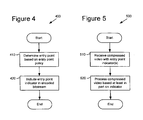
- Figure 4 is a flow chart showing a technique 400 for determining and indicating entry points in a bitstream.
- an entry point is determined in a bitstream based on an entry point policy.
- an entry point indicator is included in an encoded bitstream.
- Figure 5 is a flow chart showing a technique 500 for processing (e.g., in a video decoder) a compressed video bitstream having entry point indicators.
- compressed video with one or more entry point indicators is received (e.g., by a video decoder, video editor, splicer, etc.).
- the compressed video is processed based at least in part on the one or more entry point indicators.
- an entry point indicator can comprise an entry point start code and an entry point header.
- entry point start codes signal entry points in the bitstream.
- Entry point start codes can consist of a special 32-bit code that is not emulated anywhere else in the bitstream.
- entry point start codes can take the form of a unique sequence of 32 bits, where the first three bytes are 0x000001 and the last byte identifies the start code the entry start code.
- the entry point start code can be an abbreviated start code (e.g., one byte or a few bits) sufficient to distinguish the entry point start code from other kinds of start codes in the video stream.
- an entry point start code is located after the last of a video frame and before the beginning of the next video frame.
- Entry point start codes can be used along with other start codes in a bitstream, such as sequence start codes, frame start code, field start codes, slice start codes, and user data start codes.
- Each type of start code can be a 32-bit field.
- the various types of start codes can have different last bytes that identify the start code as a sequence start code, frame start code, field start code, slice start code, user data start code, etc.
- a start code may be preceded by an arbitrary number of "0"-valued bits, themselves preceded by a "1"-valued bit.
- the purpose of using a "10 ... 0" flushing bits sequence between the last of the previous structure and the beginning of a start code is to allow consecutive start codes to be separated by an integer number of bytes, thereby facilitating parsing of start codes by receivers.
- an entry point start code is followed immediately by an entry point header. If there is a need to insert an entry point start code and an entry point header in a position in the bitstream where there are already a sequence start code and sequence header between two consecutive video frames, the entry point start code and the entry point header follow the sequence start code and sequence header.
- an encoder can adopt different policies to govern the insertion of entry point start codes and associated headers.
- an entry point start code and associated header signal a valid entry point in the bitstream.
- the entry point start code and/or header signals the presence of a special location in a bitstream where there is no dependency on decoded video fields or frames prior to (in time order) the key frame after the entry point start code and header to decode the video frame(s) following immediately (in time order) the key frame after the entry point start code and header.
- frames that can follow entry point key frames include both frames which can themselves be entry point frames (e.g., progressive I-frames, frame interlaced I-frames, field interlaced I/I frames, field interlaced I/P frames, field interlaced P/I frames, etc.) and predicted frames, subject to certain conditions described below. The conditions for achieving this are listed in the examples below with reference to Figures 6-10 . Video frames and/or fields must satisfy certain conditions, depending on the type of picture. These conditions are only examples. Other conditions could be used.
- the type of the first frame following an entry point start code header is I if picture coding type is set to progressive or frame interlace. If the picture coding type is set to field interlace, the type of the first two fields following an entry point start code and header is I/P (I and P), P/I (P and I), or I/I (I and I).
- FIGS 6-10 reference certain bitstream constructs, definitions of which can be found in the following list:
- the reference frame for a progressive P-frame is the first I- or P-frame preceding the frame
- the reference frame(s) for a progressive B-frame may further include the first I- or P-frame following the frame.
- Similar rules apply for frame interlaced mode P-frames and B-frames.
- the reference field(s) for a P-field are, for example, one or both of the first I- or P-fields preceding the field.
- the reference field(s) for a B-field are, for example, the two temporally preceding fields and two temporally subsequent fields.
- Figure 6 illustrates how an entry point start code and header can be present before an I-frame when the picture coding type (FCM field) is set to the binary value "0" (progressive mode).
- Figure 6 also shows a sequence start code and a sequence header before the entry point start code, but this is not a requirement. An entry point start code need not always be preceded by such structures.
- the entry point applies to the I-frame that follows the entry point start code and header. It does not apply to any B-frame data or B-field data that follow that I-frame in the bitstream and for which the presentation time is earlier than the presentation time for that I-frame.
- Figure 7 illustrates how an entry point start code and header can be present before an I/P-frame when the picture coding type (FCM field) is set to the binary value "10" (field interlace mode).
- Figure 7 does not show a sequence start code and a sequence header before the entry point start code, but it may be the case that such structures precede the entry point start code.
- the entry point applies to the I/P-frame that follows the entry point start code and header but it does not apply to any B-frame data or B-field data that follow that I/P-frame in the bitstream and for which the presentation time comes earlier than the presentation time for that I/P-frame.
- Figure 8 illustrates how an entry point start code and header can be present before a P/I-frame when the picture coding type (FCM field) is set to the binary value "10" (field interlace mode).
- Figure 8 does not show a sequence start code and a sequence header before the entry point start code, but it may be the case that such structures precede the entry point start code.
- the entry point applies to the I-field that follows the entry point start code and header but it does not apply to any B-frame data that follows that I-field in the bitstream and for which the presentation time is earlier than the presentation time for that I-field. Furthermore, the entry point does not apply to the P-field data located between the entry point start code and the following I-field of the entry P/I frame.
- Figure 9 illustrates how an entry point start code and header can be present before an I/I-frame when the picture coding type (FCM field) is set to the binary value "10" (field interlace mode).
- Figure 9 does not show a sequence start code and a sequence header before the entry point start code, but it may be the case that such structures precede the entry start code.
- the entry point applies to the I/I-frame that follows the entry point start code and header, but it does not apply to any B-frame data or B-field data that follows that I/I-frame in the bitstream and for which the presentation times come earlier than the presentation time for that I/I-frame.
- Figure 10 illustrates how an entry point start code and header can be present before an I-frame when the picture coding type (FCM field) is set to the binary value "11" (frame interlace mode).
- Figure 10 also shows a sequence start code and a sequence header before the entry point start code, but it is not a requirement that an entry start code be always preceded by such structures.
- the entry point applies to the I-frame that follows the entry point start code and header, but it does not apply to any B-frame data or B-field data that follows that I-frame in the bitstream and for which the presentation times come earlier than the presentation time for that I-frame.
- the encoder and decoder may operate as follows.
- An encoder can use a policy that defines scene changes as valid entry points (and therefore ensures that the compression engine yields one of the constraints described above).
- scene changes can be detected by means of a scene change detector component that can interface (communicate) with the encoder in real time.
- Encoders can additionally use policies for generating I-frames or I-fields at particular time intervals.
- An encoder can also monitor the type and properties of the compressed video it produces and detect the points in the bitstream that verify one of the conditions such as those described in the examples for I-, I/P-, P/I- and I/I-frames stated above. Upon detecting such an event, the encoder can insert an entry point start code and an entry point header in the final bitstream.
- a video decoder could search for and render entry point frames by searching for entry point start codes.
- Entry points can be utilized by an application to produce and display a summarized version (thumbnails) of a video sequence directly from the compressed bitstream.
- Such an application can be a video editing application or a digital television electronic program guide.
- a video splicer could search for entry points to find scene changes at which splicing would be appropriate.
- the entry point header can contain information on buffer status. This information indicates buffer status that needs to be achieved to avoid buffer underflow or overflow.
- the buffer status information is stored in a field in the entry header. For example, putting buffer fullness requirement information into the entry header lets the decoder know what the minimum fullness of the buffer should be achieved before decoding can begin.
- an entry point does not apply to B-frame or B-field data that follow the entry I-frame or I-field in the bitstream and for which the presentation time is earlier than the presentation time for the I-frame or I-field.
- the entry point does apply to such B-frame or B-field data if the B-frame or B-field data is intra coded or predicted only from the entry point I-frame or I-field.
Description
- This application claims the benefit of
U.S. Provisional Patent Application Serial No. 60/520,543, filed November 13, 2003 - A portion of the disclosure of this patent document contains material which is subject to copyright protection. The copyright owner has no objection to the facsimile reproduction by any one of the patent disclosure, as it appears in the Patent and Trademark Office patent files or records, but otherwise reserves all copyright rights whatsoever.
- Techniques and tools for coding/decoding digital video are described. For example, a video encoder uses described techniques and tools for defining and signaling valid entry points in a video stream.
- Digital video consumes large amounts of storage and transmission capacity. A typical raw digital video sequence includes 15 or 30 frames per second. Each frame can include tens or hundreds of thousands of pixels (also called pels). Each pixel represents a tiny element of the picture. In raw form, a computer commonly represents a pixel as a set of three samples totaling 24 bits. Thus, the number of bits per second, or bit rate, of a typical raw digital video sequence can be 5 million bits/second or more.
- Many computers and computer networks lack the resources to process raw digital video. For this reason, engineers use compression (also called coding or encoding) to reduce the bit rate of digital video. Compression decreases the cost of storing and transmitting video by converting the video into a lower bit rate form. Decompression (also called decoding) reconstructs a version of the original video from the compressed form. A "codec" is an encoder/decoder system. Compression can be lossless, in which quality of the video does not suffer but decreases in bit rate are limited by the inherent amount of variability (sometimes called entropy) of the video data. Or, compression can be lossy, in which quality of the video suffers but achievable decreases in bit rate are more dramatic. Lossy compression is often used in conjunction with lossless compression - in a system design in which the lossy compression establishes an approximation of information and lossless compression techniques are applied to represent the approximation.
- In general, video compression techniques include "intra-picture" compression and "inter-picture" compression, where a picture is, for example, a progressively scanned video frame. For progressive video frames, intra-frame compression techniques compress individual frames (typically called I-frames or key frames). Interframe compression techniques compress frames (typically called predicted frames, P-frames, or B-frames for bi-directional prediction) with reference to preceding and/or following frames (typically called reference or anchor frames).
- A typical interlaced video frame consists of two fields scanned starting at different times. For example, an interlaced video frame includes a top field and a bottom field. Typically, the even-numbered lines (top field) are scanned starting at one time (e.g., time t) and the odd-numbered lines (bottom field) are scanned starting at a different (typically later) time (e.g., time t + 1). This timing can create jagged tooth-like features in regions of an interlaced video frame where motion is present because the two fields are scanned starting at different times. For this reason, interlaced video frames can be rearranged for coding according to a field structure, with the odd lines grouped together for coding as one field, and the even lines grouped together for coding as another field. This arrangement, known as field coding, is useful in high-motion pictures for reduction of such jagged edge artifacts. Fields in different field-coded interlaced frames can be coded differently . For example, a field in a field-coded interlaced frame can be intra-coded (e.g., an interlaced I-field) or inter-coded (e.g., an interlaced P-field or interlaced B-field).
- On the other hand, in stationary regions, image detail in the interlaced video frame may be more efficiently preserved without such a coding rearrangement. Accordingly, frame coding is often used in stationary or low-motion interlaced video frames, in which the original altemating field line arrangement is preserved. Different frame-coded interlaced frames also can be coded differently . For example, such frames can be intra-coded (e.g., an interlaced I-frame) or inter-coded (e.g., an interlaced P-frame or interlaced B-frame).
- A typical progressive video frame consists of one frame of content with non-alternating lines. In contrast to interlaced video, progressive video does not divide video frames into separate fields, and an entire frame is scanned left to right, top to bottom starting at a single time. Progressive frames can be intra-coded (e.g., a progressive I-frame) or inter-coded (e.g., a progressive P-frame or progressive B-frame).
- Several international standards relate to video compression and decompression. These standards include the Motion Picture Experts Group ["MPEG"] 1, 2, and 4 standards and the H.261, H.262 (another title for MPEG 2), H.263 and H.264 (also called JVT/AVC) standards from the international Telecommunication Union ["ITU"]. These standards specify aspects of video decoders and formats for compressed video information. Directly or by implication, they also specify certain encoder details, but other encoder details are not specified. These standards use (or support the use of) different combinations of intraframe and interframe decompression and compression. In particular, they use or support the use of different "access points" for decoders and/or editors.
- The MPEG 2/H.262 standard describes intra-coded pictures (e.g., coded I-frames) and group-of-pictures (GOP) headers. In MPEG 2, intra-coded pictures are coded without reference to other pictures and provide access points to the coded sequence where decoding can begin. Intra-coded pictures can be used at different places in a video sequence. For example, intra-coded pictures can be inserted periodically or can be used in places such as scene changes or where motion compensation is otherwise ineffective. A coded I-frame is an I-frame picture or a pair of field pictures, where the first field picture is an I-picture and the second field picture is an I-picture or a P-picture. The MPEG 2 standard does not allow a coded I-frame in which the first field picture is a P-picture and the second field picture is an I-picture.
- A GOP header is a construct in the MPEG 2 bitstream that signals the beginning of a group of pictures. Groups of pictures are typically used to signal the boundary of a set of video frames/fields all encoded with reference to the same I-frame. A GOP header is an optional header that may be signaled immediately before a coded I-frame to indicate if the first consecutive B-pictures (if any) immediately following the coded I-frame in the bitstream (but typically preceding the coded I-frame in display order) can be reconstructed properly in the case of a random access. For such B-pictures, if a reference picture before the current coded I-frame is not available, the B-pictures cannot be reconstructed properly unless they only use backward prediction from the current coded I-frame or intra coding. A decoder may use this information to avoid displaying B-pictures that cannot be correctly decoded. For a decoder, the GOP header thus indicates how the decoder can perform decoding from the GOP header, even if the GOP header is in the middle of a video sequence. The GOP header includes a start code called group_start_code. The GOP header start code includes a 24-bit start code prefix (23 0s followed by a 1) followed by the GOP header start code value (B8 in hexadecimal). Start codes in MPEG 2 are byte-aligned; 0s are to be inserted before the beginning of the start code prefix to ensure byte alignment. For additional information, see the H.262 standard.
- The MPEG 4 standard describes intra-coded video object planes (I-VOPs) and group of video object plane (VOP) headers. An I-VOP is a VOP coded using information only from itself. Non-intra-coded VOPs may be derived from progressive or interlaced frames. In MPEG 4, I-VOPs are coded without reference to other pictures and provide access points to the coded sequence where decoding can begin. A group of VOP header is an optional header that can be used immediately before a coded I-VOP to indicate to the decoder if the first consecutive B-VOPs immediately following the coded I-frame can be reconstructed properly in the case of a random access. A group of VOP header must be followed by a coded I-VOP. A group of VOPs start code includes a 24-bit start code prefix (23 0s followed by a 1) followed by the group of VOPs start code value (B3 in hexadecimal). Start codes in MPEG 4 are byte-aligned and the standard provides for bit-stuffing to achieve byte alignment. For example, for stuffing from one to eight bits, a 0 followed by from one to seven 1s are inserted prior to the start code, so long as the previous code was not a start code. For additional information, see the MPEG 4 standard.
- According to draft JVT-d157 of the JVT/AVC video standard, I-pictures provide access points to a coded sequence where decoding can begin, and various information used in decoding is signaled in network abstraction layer ("NAL") units. A NAL unit indicates what type of data to expect in the NAL unit, followed by the data itself, interspersed with emulation prevention data. A supplemental enhancement information ("SEI") NAL unit is a type of NAL unit. An SEI NAL unit contains one or more SEI messages. Each SEI message consists of SEI header and SEI payload. The type and size of the SEI payload are coded using an extensible syntax. The SEI payload may have a SEI payload header. For example, a payload header may indicate to which picture the particular data belongs.
- Annex C of draft JVT-d157 establishes rules for dealing with hypothetical reference decoder ("HRD") buffers. For example, at each decoder refresh point a buffering period SEI message shall follow the last NAL unit of the last picture before a decoder refresh and precede the first NAL unit of the first picture after the decoder refresh. An HRD picture SEI message must follow the last NAL unit of each picture and precede the first NAL unit of the next picture. Each of these SEI messages pertains to the picture that follows it.
- Annex D of the draft JVT-d157 describes a syntax for a random access point SEI message. A random access point SEI message contains an indicator of a random access entry point for a decoder. The entry point is indicated as a count relative to the position of the SEI message in units of coded frame numbers prior to the frame number of the current picture. Annex D states that a buffering period SEI message should be transmitted at the location of the random access entry point indicated in the random access point SEI message in order to establish initialization of the HRD buffer model.
- These international standards are limited in several important ways. For example, in MPEG 2, the first coded frame after a GOP header must be a "coded I-frame" -- an intra-coded frame picture or a pair of field pictures where the first field picture is an I-picture and the second field picture is either an I-picture or a P-picture. GOP headers are not allowed to precede any other frame type. In MPEG 4, a group of VOP header must be followed by a coded I-VOP.
- Given the critical importance of video compression and decompression to digital video, it is not surprising that video compression and decompression are richly developed fields. Whatever the benefits of previous video compression and decompression techniques, however, they do not have the advantages of the following techniques and tools.
- Suzuki, Yagasati: "Study of Random Access for JVT", ITU Study Group 16 - Video Coding Experts Group - ISO/IEC MPEG & ITU-T VCEG (ISO/IEC JTC1/SC29/WG11 and ITU-T SG16 Q6), XX, XX, no. JVT-C054, 10 May 2002 relates to studies on random access for JVT. It is stated that splicing is one of the important functionalities of codec and JVT codec should support it. There are two types of splicing: seamless splicing and non-seamless splicing. Seamless splicing allows clean instantaneous switching of streams. Non-seamless splicing avoids decoder buffer overflow by inserting short dead time between two. The splice point should be a random access point and new stream follows random access point header.
- WANG: "Signaling of Shot Changes", ITU STUDY GROUP 16 - Video Coding Experts Group - ISO/IEC MPEG & ITU-T VCEG (ISO/IEC JTC1/SC29/WG11 and ITU-T SG16 Q6), XX, XX, no. JVT-D099, 26 July 2002 relates to signaling of shot changes in the JVT bitstream. Shot changes are embodied by scene transitions in video contents. For the purposes of shot detection and error concealment, two kinds of information are needed: 1) in which frames the shot change starts and ends; 2) the type of the scene transition. Since the information is not necessary for correct decoding of the video coding layer data, it is proposed to signal the information as supplemented enhancement information (SEI). An encoder should generate scene information SEI messages. The following guidelines are recommended: an encoder should create a scene information SEI message for each scene cut in gradual transition. For each scene cut picture, there should be an associated scene information SEI message that is preferably repeated later for error resilience. For each gradual scene transition, there should be a scene information SEI message associated with the first transition picture. For each gradual scene transition, there should also be a scene information SEI message associated with the first picture after the last transition picture.
- Miska M Hannuksela et al: "Random Access and Time Information", ITU Study Group 16 - Video Coding Experts Group - ISO/IEC MPEG & ITU-T VCEG (ISO/IEC JTC1/SC29/WG11 and ITU-T SG16 Q6), XX, XX, no. JVT-B109, 1 February 2002 relates to syntax and semantics for random access and for timing information. A dedicated NAL packet type is reserved for instantaneous random access positions in order to enable its detection easily.
- It is the object of the present invention to simplify prior art techniques. This object is solved by the subject matter of the independent claims. Preferred embodiments are defined by the dependent claims.
- In summary, the detailed description is directed to various techniques and tools for coding/decoding of digital video. In particular, described embodiments include techniques and tools for determining and signaling entry points in video streams.
- Video compression typically relies on temporal correlation across video fields or video frames to compress video content efficiently. As a result, compression of video fields/frames introduces temporal dependence across these fields and frames. Techniques and tools described herein are used to embed entry point indicator information in the bitstream that receivers, editing systems or insertion systems can use to detect valid entry points in compressed video. The embedded information can be used, for example, in implementation of "trick" modes (e.g., fast forward, fast rewind, etc.) by allowing a video decoder to jump from one entry point or key frame to another. The various techniques and tools can be used in combination or independently.
- Additional features and advantages will be made apparent from the following detailed description of different embodiments that proceeds with reference to the accompanying drawings.
-
-
Figure 1 is a block diagram of a suitable computing environment in which several described embodiments may be implemented. -
Figure 2 is a block diagram of a generalized video encoder system used in several described embodiments. -
Figure 3 is a block diagram of a generalized video decoder system used in several described embodiments. -
Figure 4 is a flow chart showing a technique for determining and indicating entry points in a bitstream. -
Figure 5 is a flow chart showing a technique for processing a compressed video bitstream having entry point indicators. -
Figure 6 is a diagram showing a bitstream syntax for signaling an entry point before a progressive I frame. -
Figure 7 is a diagram showing a bitstream syntax for signaling an entry point before an I/P frame. -
Figure 8 is a diagram showing a bitstream syntax for signaling an entry point before a P/I frame. -
Figure 9 is a diagram showing a bitstream syntax for signaling an entry point before an I/I frame. -
Figure 10 is a diagram showing a bitstream syntax for signaling an entry point before an interlace I frame. - The present application relates to techniques and tools for determining and signaling valid entry points in compressed video. In this context, "determining" can mean, for example, detecting whether a video frame is a valid entry point in the bitstream once it has been compressed, or enforcing rules or policies to guarantee production of valid entry points at compression time. A bitstream format or syntax includes flags and other codes to incorporate the techniques. The bitstream format comprises different layers or levels (e.g., sequence level, frame/picture/image level, macroblock level, and/or block level).
- Described techniques and tools introduce conditions for a video frame or a video field to be a valid entry point in a bitstream. These conditions represent policies that a video encoder enforces during encoding of a video sequence to produce entry points in bitstreams (in order to enable "trick" modes, for example). The policies can produce entry points in the bitstream at different locations. For example, policies can direct entry points to be provided when a scene change occurs or to indicate where a commercial can be inserted to facilitate activities such as video summarization and splicing, respectively. The policies governing the insertion of entry points in the bitstream can also be designed such that entry points are provided at regular intervals and at specific time intervals (for example, to minimize latency upon tuning to the service). Described techniques and tools are also directed to the mechanisms by which entry points can be signaled unambiguously in an elementary stream. This can be achieved by a special start code followed by an entry header.
- The various techniques and tools can be used in combination or independently. Different embodiments implement one or more of the described techniques and tools.
-
Figure 1 illustrates a generalized example of asuitable computing environment 100 in which several of the described embodiments may be implemented. Thecomputing environment 100 is not intended to suggest any limitation as to scope of use or functionality, as the techniques and tools may be implemented in diverse general-purpose or special-purpose computing environments. - With reference to
Figure 1 , thecomputing environment 100 includes at least oneprocessing unit 110 andmemory 120. InFigure 1 , this mostbasic configuration 130 is included within a dashed line. Theprocessing unit 110 executes computer-executable instructions and may be a real or a virtual processor. In a multi-processing system, multiple processing units execute computer-executable instructions to increase processing power. Thememory 120 may be volatile memory (e.g., registers, cache, RAM), non-volatile memory (e.g., ROM, EEPROM, flash memory, etc.), or some combination of the two. Thememory 120stores software 180 implementing a video encoder or decoder with entry point processing. - A computing environment may have additional features. For example, the
computing environment 100 includesstorage 140, one ormore input devices 150, one ormore output devices 160, and one ormore communication connections 170. An interconnection mechanism (not shown) such as a bus, controller, or network interconnects the components of thecomputing environment 100. Typically, operating system software (not shown) provides an operating environment for other software executing in thecomputing environment 100, and coordinates activities of the components of thecomputing environment 100. - The
storage 140 may be removable or non-removable, and includes magnetic disks, magnetic tapes or cassettes, CD-ROMs, DVDs, or any other medium which can be used to store information and which can be accessed within thecomputing environment 100. Thestorage 140 stores instructions for thesoftware 180 implementing the video encoder or decoder. - The input device(s) 150 may be a touch input device such as a keyboard, mouse, pen, or trackball, a voice input device, a scanning device, or another device that provides input to the
computing environment 100. For audio or video encoding, the input device(s) 150 may be a sound card, video card, TV tuner card, or similar device that accepts audio or video input in analog or digital form, or a CD-ROM or CD-RW that reads audio or video samples into thecomputing environment 100. The output device(s) 160 may be a display, printer, speaker, CD-writer, or another device that provides output from thecomputing environment 100. - The communication connection(s) 170 enable communication over a communication medium to another computing entity. The communication medium conveys information such as computer-executable instructions, audio or video input or output, or other data in a modulated data signal. A modulated data signal is a signal that has one or more of its characteristics set or changed in such a manner as to encode information in the signal. By way of example, and not limitation, communication media include wired or wireless techniques implemented with an electrical, optical, RF, infrared, acoustic, or other carrier.
- The techniques and tools can be described in the general context of computer-readable media. Computer-readable media are any available media that can be accessed within a computing environment. By way of example, and not limitation, within the
computing environment 100, computer-readable media includememory 120,storage 140, communication media, and combinations of any of the above. - The techniques and tools can be described in the general context of computer-executable instructions, such as those included in program modules, being executed in a computing environment on a target real or virtual processor. Generally, program modules include routines, programs, libraries, objects, classes, components, data structures, etc. that perform particular tasks or implement particular abstract data types. The functionality of the program modules may be combined or split between program modules as desired in various embodiments. Computer-executable instructions for program modules may be executed within a local or distributed computing environment.
- For the sake of presentation, the detailed description uses terms like "determine," "enforce," and "provide" to describe computer operations in a computing environment. These terms are high-level abstractions for operations performed by a computer, and should not be confused with acts performed by a human being. The actual computer operations corresponding to these terms vary depending on implementation.
-
Figure 2 is a block diagram of ageneralized video encoder 200 andFigure 3 is a block diagram of ageneralized video decoder 300. - The relationships shown between modules within the encoder and decoder indicate the main flow of information in the encoder and decoder, other relationships are not shown for the sake of simplicity. In particular,
Figures 2 and3 generally do not show side information indicating the encoder settings, modes, tables, etc. used for a video sequence, frame, macroblock, block, etc. Such side information is sent in the output bitstream, typically after entropy encoding of the side information. The format of the output bitstream can be a Windows Media Video format or another format. - The
encoder 200 anddecoder 300 are block-based and use a 4:2:0 macroblock format. Alternatively, theencoder 200 anddecoder 300 are object-based or use a different macroblock or block format. - Depending on implementation and the type of compression desired, modules of the encoder or decoder can be added, omitted, split into multiple modules, combined with other modules, and/or replaced with like modules. In alternative embodiments, encoder or decoders with different modules and/or other configurations of modules perform one or more of the described techniques.
-
Figure 2 is a block diagram of a generalvideo encoder system 200. Theencoder system 200 receives a sequence of video frames including acurrent frame 205, and produces compressedvideo information 295 as output. Particular embodiments of video encoders typically use a variation or supplemented version of thegeneralized encoder 200. - The
encoder system 200 compresses predicted frames and key frames. For the sake of presentation,Figure 2 shows a path for key frames through theencoder system 200 and a path for predicted frames. Many of the components of theencoder system 200 are used for compressing both key frames and predicted frames. The exact operations performed by those components can vary depending on the type of information being compressed. - A predicted frame (also called P-frame, B-frame for bi-directional prediction, or inter-coded frame) is represented in terms of prediction (or difference) from one or more reference (or anchor) frames. A prediction residual is the difference between what was predicted and the original frame. In contrast, a key frame (also called I-frame, intra-coded frame) is compressed without reference to other frames. Intra-coded frames include progressive I-frames, interlaced I-frames (frame interlaced mode), and I/I frames (field interlaced mode). Parts of other frames also can be compressed without reference to other frames. For example, the I-fields of I/P-frames and P/I frames are compressed without reference to other frames and are described in detail below. In some cases, the P-fields of I/P frames are compressed without reference to other frames, as described in detail below.
- If the
current frame 205 is a forward-predicted frame, amotion estimator 210 estimates motion of macroblocks or other sets of pixels of thecurrent frame 205 with respect to a reference frame, which is the reconstructedprevious frame 225 buffered in a frame store (e.g., frame store 220). If thecurrent frame 205 is a bi-directionally-predicted frame (a B-frame), amotion estimator 210 estimates motion in thecurrent frame 205 with respect to two reconstructed reference frames. Typically, a motion estimator estimates motion in a B-frame with respect to a temporally previous reference frame and a temporally future reference frame. - The
motion estimator 210 outputs as sideinformation motion information 215 such as motion vectors. Amotion compensator 230 applies themotion information 215 to the reconstructed frame(s) 225 to form a motion-compensatedcurrent frame 235. The prediction is rarely perfect, however, and the difference between the motion-compensatedcurrent frame 235 and the originalcurrent frame 205 is the prediction residual 245. Alternatively, a motion estimator and motion compensator apply another type of motion estimation/compensation. - A
frequency transformer 260 converts the spatial domain video information into frequency domain (i.e., spectral) data. Aquantizer 270 then quantizes the blocks of spectral data coefficients. In addition to quantization, theencoder 200 can use frame dropping, adaptive filtering, or other techniques for rate control. - When a reconstructed current frame is needed for subsequent motion estimation/compensation, an
inverse quantizer 276 performs inverse quantization on the quantized spectral data coefficients. Aninverse frequency transformer 266 then performs the inverse of the operations of thefrequency transformer 260, producing a reconstructed prediction residual (for a predicted frame) or a reconstructed key frame. If thecurrent frame 205 was a key frame, the reconstructed key frame is taken as the reconstructed current frame (not shown). If thecurrent frame 205 was a predicted frame, the reconstructed prediction residual is added to the motion-compensatedcurrent frame 235 to form the reconstructed current frame. A frame store (e.g., frame store 220) buffers the reconstructed current frame for use in predicting another frame. - The
entropy coder 280 compresses the output of thequantizer 270 as well as certain side information (e.g.,motion information 215, quantization step size). Typical entropy coding techniques include arithmetic coding, differential coding, Huffman coding, run length coding, LZ coding, dictionary coding, and combinations of the above. - The
entropy coder 280 puts compressedvideo information 295 in thebuffer 290. A buffer level indicator is fed back to bit rate adaptive modules. Thecompressed video information 295 is depleted from thebuffer 290 at a constant or relatively constant bit rate and stored for subsequent streaming at that bit rate. Therefore, the level of thebuffer 290 is primarily a function of the entropy of the filtered, quantized video information, which affects the efficiency of the entropy coding. Alternatively, theencoder system 200 streams compressed video information immediately following compression, and the level of thebuffer 290 also depends on the rate at which information is depleted from thebuffer 290 for transmission. - Before or after the
buffer 290, thecompressed video information 295 can be channel coded for transmission over the network. The channel coding can apply error detection and correction data to thecompressed video information 295. -
Figure 3 is a block diagram of a generalvideo decoder system 300. Thedecoder system 300 receivesinformation 395 for a compressed sequence of video frames and produces output including a reconstructedframe 305. Particular embodiments of video decoders typically use a variation or supplemented version of thegeneralized decoder 300. - The
decoder system 300 decompresses predicted frames and key frames. For the sake of presentation,Figure 3 shows a path for key frames through thedecoder system 300 and a path for predicted frames. Many of the components of thedecoder system 300 are used for decompressing both key frames and predicted frames. The exact operations performed by those components can vary depending on the type of information being decompressed. - A
buffer 390 receives theinformation 395 for the compressed video sequence and makes the received information available to theentropy decoder 380. Thebuffer 390 typically receives the information at a rate that is fairly constant over time, and includes a jitter buffer to smooth short-term variations in bandwidth or transmission. Thebuffer 390 can include a playback buffer and other buffers as well. Alternatively, thebuffer 390 receives information at a varying rate. Before or after thebuffer 390, the compressed video information can be channel decoded and processed for error detection and correction. - The
entropy decoder 380 entropy decodes entropy-coded quantized data as well as entropy-coded side information (e.g.,motion information 315, quantization step size), typically applying the inverse of the entropy encoding performed in the encoder. - A
motion compensator 330 appliesmotion information 315 to one ormore reference frames 325 to form aprediction 335 of theframe 305 being reconstructed. For example, themotion compensator 330 uses a macroblock motion vector to find a macroblock in areference frame 325. A frame buffer (e.g., frame buffer 320) stores previously reconstructed frames for use as reference frames. Typically, B-frames have more than one reference frame (e.g., a temporally previous reference frame and a temporally future reference frame). The prediction by the motion compensator is rarely perfect, so thedecoder 300 also reconstructs prediction residuals. - When the decoder needs a reconstructed frame for subsequent motion compensation, a frame buffer (e.g., frame buffer 320) buffers the reconstructed frame for use in predicting another frame.
- An
inverse quantizer 370 inverse quantizes entropy-decoded data. Aninverse frequency transformer 360 converts the quantized, frequency domain data into spatial domain video information. - Valid entry points in a bitstream are locations in an elementary bitstream from which a system (e.g., a receiver, a video splicer, a commercial insertion tool, a video editor, a summarization engine, etc.) can decode or process the bitstream without the need of any preceding information (bits) in the bitstream. Frames that can be decoded without reference to preceding frames are typically referred to as "key" frames.
- An entry point is signaled in a bitstream by an entry point indicator. The purpose of an entry point indicator is to signal the presence of a special location in a bitstream to begin or resume decoding (e.g., where there is no dependency on past decoded video fields or frames to decode the video frame following immediately the entry point indicator). Entry point indicators can be inserted at regular or irregular intervals in a bitstream. Therefore, an encoder can adopt different policies to govern the insertion of entry point indicators in a bitstream.
-
Figure 4 is a flow chart showing atechnique 400 for determining and indicating entry points in a bitstream. At 410, an entry point is determined in a bitstream based on an entry point policy. Then, at 420, an entry point indicator is included in an encoded bitstream.Figure 5 is a flow chart showing atechnique 500 for processing (e.g., in a video decoder) a compressed video bitstream having entry point indicators. At 510, compressed video with one or more entry point indicators is received (e.g., by a video decoder, video editor, splicer, etc.). Then, at 520, the compressed video is processed based at least in part on the one or more entry point indicators. - As an example, an entry point indicator can comprise an entry point start code and an entry point header.
- In some implementations, entry point start codes signal entry points in the bitstream. Entry point start codes can consist of a special 32-bit code that is not emulated anywhere else in the bitstream. For example, entry point start codes can take the form of a unique sequence of 32 bits, where the first three bytes are 0x000001 and the last byte identifies the start code the entry start code. However, more compact representations of the start code are allowed if the underlying transport includes enough signaling to provide similar information. For example, the entry point start code can be an abbreviated start code (e.g., one byte or a few bits) sufficient to distinguish the entry point start code from other kinds of start codes in the video stream. In some implementations, an entry point start code is located after the last of a video frame and before the beginning of the next video frame.
- Entry point start codes can be used along with other start codes in a bitstream, such as sequence start codes, frame start code, field start codes, slice start codes, and user data start codes. Each type of start code can be a 32-bit field. The various types of start codes can have different last bytes that identify the start code as a sequence start code, frame start code, field start code, slice start code, user data start code, etc.
- A start code may be preceded by an arbitrary number of "0"-valued bits, themselves preceded by a "1"-valued bit. The purpose of using a "10 ... 0" flushing bits sequence between the last of the previous structure and the beginning of a start code is to allow consecutive start codes to be separated by an integer number of bytes, thereby facilitating parsing of start codes by receivers. Before the start code and after the last '0'-valued flushing bit, it is also possible to add an arbitrary number of 0x00-valued bytes.
- In some implementations, an entry point start code is followed immediately by an entry point header. If there is a need to insert an entry point start code and an entry point header in a position in the bitstream where there are already a sequence start code and sequence header between two consecutive video frames, the entry point start code and the entry point header follow the sequence start code and sequence header.
- Since an entry point start code and an entry point header may be inserted at regular or irregular intervals in a bitstream, an encoder can adopt different policies to govern the insertion of entry point start codes and associated headers.
- In some implementations, an entry point start code and associated header signal a valid entry point in the bitstream. Put differently, the entry point start code and/or header signals the presence of a special location in a bitstream where there is no dependency on decoded video fields or frames prior to (in time order) the key frame after the entry point start code and header to decode the video frame(s) following immediately (in time order) the key frame after the entry point start code and header. Thus, frames that can follow entry point key frames include both frames which can themselves be entry point frames (e.g., progressive I-frames, frame interlaced I-frames, field interlaced I/I frames, field interlaced I/P frames, field interlaced P/I frames, etc.) and predicted frames, subject to certain conditions described below. The conditions for achieving this are listed in the examples below with reference to
Figures 6-10 . Video frames and/or fields must satisfy certain conditions, depending on the type of picture. These conditions are only examples. Other conditions could be used. - These conditions depend on the type of the first frames/fields after the entry point. In these examples, the type of the first frame following an entry point start code header is I if picture coding type is set to progressive or frame interlace. If the picture coding type is set to field interlace, the type of the first two fields following an entry point start code and header is I/P (I and P), P/I (P and I), or I/I (I and I).
-
Figures 6-10 reference certain bitstream constructs, definitions of which can be found in the following list: - SEQ_SC: Sequence Start Code
- SEQ_HDR: Sequence Header
- ENTRY_SC: Entry Point Start Code
- ENTRY_HDR: Entry Point Header
- FRAME_SC: Frame Start Code
- FRAME_HDR: Frame Header
- FIELD_SC: Field Start Code
- FIELD_HDR: Field Header
- UD_SC: User Data Start Code
- UD_BYT: User Data Bytes
- The following diagrams and discussion incorporate certain rules for positions of reference fields and frames. In general, the reference frame for a progressive P-frame is the first I- or P-frame preceding the frame, and the reference frame(s) for a progressive B-frame may further include the first I- or P-frame following the frame. Similar rules apply for frame interlaced mode P-frames and B-frames. For field interlaced frames, the reference field(s) for a P-field are, for example, one or both of the first I- or P-fields preceding the field. The reference field(s) for a B-field are, for example, the two temporally preceding fields and two temporally subsequent fields.
-
Figure 6 illustrates how an entry point start code and header can be present before an I-frame when the picture coding type (FCM field) is set to the binary value "0" (progressive mode).Figure 6 also shows a sequence start code and a sequence header before the entry point start code, but this is not a requirement. An entry point start code need not always be preceded by such structures. - Since the frame is intra-coded, no additional condition is needed to make this I-frame a valid entry point in a bitstream. The entry point applies to the I-frame that follows the entry point start code and header. It does not apply to any B-frame data or B-field data that follow that I-frame in the bitstream and for which the presentation time is earlier than the presentation time for that I-frame.
-
Figure 7 illustrates how an entry point start code and header can be present before an I/P-frame when the picture coding type (FCM field) is set to the binary value "10" (field interlace mode).Figure 7 does not show a sequence start code and a sequence header before the entry point start code, but it may be the case that such structures precede the entry point start code. - Since the frame is made of an I-field followed by a P-field, the following conditions shall be met to make this I/P frame a valid entry point in a bitstream:
- The value of the "numref' field in the field header of the P-field of the entry I/P-frame shall be the binary value "0".
- The value of the "reffield" field in the field header of the P-field of the entry I/P-frame shall be the binary value "0".
- The entry point applies to the I/P-frame that follows the entry point start code and header but it does not apply to any B-frame data or B-field data that follow that I/P-frame in the bitstream and for which the presentation time comes earlier than the presentation time for that I/P-frame.
-
Figure 8 illustrates how an entry point start code and header can be present before a P/I-frame when the picture coding type (FCM field) is set to the binary value "10" (field interlace mode).Figure 8 does not show a sequence start code and a sequence header before the entry point start code, but it may be the case that such structures precede the entry point start code. - Since the frame is made of a P-field followed by an I-field, the following conditions shall be met to make this P/I-frame a valid entry point in a bitstream:
- Following the entry I-field of the P/I frame, a P/P-frame in field interlace mode shall be present in the bitstream before any occurrence of P-frames in progressive or frame interlaced modes.
- The value of the "numref" field in the field header of the first P-field following the entry P/I-frame shall be the binary value "0".
- The value of the "reffield" field in the field header of the first P-field following the entry P/I-frame shall be the binary value "0".
- Any B-frames following the entry P/I-frame in the bitstream and for which the presentation time comes later than the presentation times for that entry P/I-frame shall not be encoded as depending on the P/I-frame.
- The first (in temporal order) B-field of any B/B-frames following the entry P/I-frame in the bitstream and for which the presentation time comes later than the presentation times of that P/I-frame shall not be encoded as depending on the P-field of the entry P/I-frame.
- The entry point applies to the I-field that follows the entry point start code and header but it does not apply to any B-frame data that follows that I-field in the bitstream and for which the presentation time is earlier than the presentation time for that I-field. Furthermore, the entry point does not apply to the P-field data located between the entry point start code and the following I-field of the entry P/I frame.
-
Figure 9 illustrates how an entry point start code and header can be present before an I/I-frame when the picture coding type (FCM field) is set to the binary value "10" (field interlace mode).Figure 9 does not show a sequence start code and a sequence header before the entry point start code, but it may be the case that such structures precede the entry start code. - Since the I/I-frame is made of two I-fields, no additional condition is needed to make this frame a valid entry point in a bitstream.
- The entry point applies to the I/I-frame that follows the entry point start code and header, but it does not apply to any B-frame data or B-field data that follows that I/I-frame in the bitstream and for which the presentation times come earlier than the presentation time for that I/I-frame.
-
Figure 10 illustrates how an entry point start code and header can be present before an I-frame when the picture coding type (FCM field) is set to the binary value "11" (frame interlace mode).Figure 10 also shows a sequence start code and a sequence header before the entry point start code, but it is not a requirement that an entry start code be always preceded by such structures. - Since the frame is intra-coded, no additional condition is needed to make this I-frame a valid entry point in a bitstream. The entry point applies to the I-frame that follows the entry point start code and header, but it does not apply to any B-frame data or B-field data that follows that I-frame in the bitstream and for which the presentation times come earlier than the presentation time for that I-frame.
- In conjunction with or in addition to the various alternatives described above, the encoder and decoder may operate as follows.
- Policies assess whether a point in a bitstream is a valid entry point. An encoder can use a policy that defines scene changes as valid entry points (and therefore ensures that the compression engine yields one of the constraints described above). In this case, scene changes can be detected by means of a scene change detector component that can interface (communicate) with the encoder in real time. Encoders can additionally use policies for generating I-frames or I-fields at particular time intervals.
- An encoder can also monitor the type and properties of the compressed video it produces and detect the points in the bitstream that verify one of the conditions such as those described in the examples for I-, I/P-, P/I- and I/I-frames stated above. Upon detecting such an event, the encoder can insert an entry point start code and an entry point header in the final bitstream.
- In modes such as fast-forward or fast-rewind, a video decoder could search for and render entry point frames by searching for entry point start codes.
- Entry points can be utilized by an application to produce and display a summarized version (thumbnails) of a video sequence directly from the compressed bitstream. Such an application can be a video editing application or a digital television electronic program guide.
- For performing video splicing, a video splicer could search for entry points to find scene changes at which splicing would be appropriate.
- The entry point header can contain information on buffer status. This information indicates buffer status that needs to be achieved to avoid buffer underflow or overflow. The buffer status information is stored in a field in the entry header. For example, putting buffer fullness requirement information into the entry header lets the decoder know what the minimum fullness of the buffer should be achieved before decoding can begin.
- In several examples above, an entry point does not apply to B-frame or B-field data that follow the entry I-frame or I-field in the bitstream and for which the presentation time is earlier than the presentation time for the I-frame or I-field. Altematively, the entry point does apply to such B-frame or B-field data if the B-frame or B-field data is intra coded or predicted only from the entry point I-frame or I-field.
- Having described and illustrated the principles of our invention with reference to various embodiments, it will be recognized that the various embodiments can be modified in arrangement and detail without departing from such principles. It should be understood that the programs, processes, or methods described herein are not related or limited to any particular type of computing environment, unless indicated otherwise. Various types of general purpose or specialized computing environments may be used with or perform operations in accordance with the teachings described herein. Elements of embodiments shown in software may be implemented in hardware and vice versa.
- In view of the many possible embodiments to which the principles of our invention may be applied, we claim as our invention all such embodiments as may come within the scope of the following claims and equivalents thereto.
Claims (51)
- A method comprising:determining (410) one or more entry points for a sequence comprising plural video frames based at least in part on an entry point policy, wherein the entry point policy comprises one or more conditions for entry point indicator positioning; andinserting (420) in a bitstream an entry point indicator that indicates a first frame of the plural frames is one of the one or more entry points, wherein the entry point indicator comprises an entry point header and wherein the first frame has a type selected from a set of types comprising field interlaced P/I frame,characterized in thatthe entry point indicator comprises an entry point start code, the entry point start code is followed immediately by the entry point header, wherein the entry point start code and the entry point header signal the one of the one or more entry points; andafter the entry point indicator the bitstream includes a frame start code and a frame header, wherein the frame start code immediately follows the entry point header and the frame header immediately follows the frame start code, and wherein the frame header comprises a field indicating the type of the first frame.
- The method of claim 1 wherein the set of types further comprises: frame interlaced I-frame, field interlaced I/P-frame, field interlaced I/I-frame, and progressive I-frame.
- The method of claim 1 wherein the one or more entry points comprises plural entry points positioned at different intervals.
- The method of claim 1 wherein the entry point header includes buffer fullness information.
- The method of claim 1 wherein the entry point start code is an abbreviated start code sufficient to distinguish the entry point start code from other start codes in the bitstream.
- The method of claim 1 wherein the bitstream has plural syntax levels, and
wherein the entry point indicator is included at a syntax level below sequence level. - The method of claim 6 wherein the syntax level below sequence level is entry point level.
- The method of claim 1 wherein the entry point indicator immediately follows a sequence header in the bitstream.
- The method of claim 1 wherein the entry point indicator indicates a commercial insertion point to facilitate video splicing.
- The method of claim 1 wherein the first frame is a field interlaced P/I-frame, wherein the field interlaced P/I-frame contains an interlaced P-field followed by an interlaced I-field, the P-field and the I-field being arranged in the bitstream for decoding as individual fields, wherein a second frame immediately follows the field interlaced P/I-frame in presentation time, wherein the second frame is a predicted frame, wherein according to the entry point policy the video encoder makes coding decisions for the second frame to remove any motion compensation dependencies prior to the I-field of the field interlaced P/I-frame, and wherein the entry point policy comprises conditions that include:after the field interlaced P/I-frame, at least one field interlaced P/P-frame is present in the bitstream before a progressive P-frame or frame interlaced P-frame;after the field interlaced P/I-frame, a next P-field in the bitstream references the I-field of the field interlaced P/I-frame but not the P-field of the field interlaced P/I-frame;after the field interlaced P/I-frame, a progressive B-frame or frame interlaced B-frame in the bitstream that has a later presentation time than the field interlaced P/I-frame is not encoded depending on the field interlaced P/I-frame; andafter the field interlaced P/I-frame, a next B-field in the bitstream that has a later presentation time than the field interlaced P/I-frame is not encoded depending on the P-field of the field interlaced P/I-frame.
- The method of claim 1 wherein, according to the entry point policy, entry point indicators are inserted in the bitstream at regular intervals.
- The method of claim 1 wherein, according to the entry point policy, entry point indicators are inserted in the bitstream at scene changes.
- The method of claim 1, further comprising:inserting a commercial at the entry point.
- The method of claim 1 wherein the field indicating the type of the first frame indicates a combination of field types for a pair of interlaced video fields of the first frame.
- The method of claim 1 wherein the first frame is a frame interlaced I-frame, the one or more conditions further comprising no other restrictions.
- The method of claim 1 wherein the first frame is a progressive I-frame, the one or more conditions further comprising no other restrictions.
- The method of claim 1 wherein the first frame is a field interlaced I/I-frame, the conditions further comprising no other restrictions.
- The method of claim 1 wherein the first frame is a field interlaced I/P-frame, wherein the field interlaced I/P-frame contains an interlaced I-field followed by an interlaced P-field, the one or more conditions further comprising:the interlaced P-field is only predicted from the interlaced I-field.
- The method of claim 18 wherein a numref field in a field header for the interlaced P-field is set to 0, and wherein a reffield field in the field header for the interlaced P-field is set to 0.
- The method of claim 1 wherein the first frame is a field interfaced P/I-frame, and wherein the field interlaced P/I-frame contains an interlaced P-field followed by an interlaced I-field, the one or more conditions further comprising:a P-field of a field interlaced P/P-frame following the field interlaced P/I-frame is not predicted from the interlaced P-field of the field interlaced P/I frame.
- The method of claim 1 wherein the first frame is a field interlaced P/I-frame, and wherein the field interfaced P/I frame contains an interlaced P-field followed by an interlaced I-field, the one or more conditions further comprising:a B-field of a field interlaced B/B-frame following the field interlaced P/I frame is not predicted from the interlaced P-field of the field interlaced P/I frame.
- The method of claim 1 wherein the first frame is a field interlaced P/I-frame, and wherein the field interlaced P/I-frame contains an interlaced P-field followed by an interlaced I-field, the one or more conditions further comprising:a frame interlaced B-frame following the field interlaced P/I-frame is not predicted from the field interlaced P/I-frame.
- The method of claim 1 wherein the first frame is a field interlaced P/I-frame, and wherein the field interlaced P/I frame contains an interlaced P-field followed by an interlaced I-field, the one or more conditions further comprising:a frame interlaced P-frame following the field interlaced P/I-frame is not predicted from the field interlaced P/I-frame.
- The method of claim 1 wherein the first frame is a field interlaced P/I-frame, wherein the field interlaced P/I-frame contains an interlaced P-field followed by an interlaced I-field, and wherein a frame following the field interlaced P/I-frame is a frame selected from the set comprising: frame interfaced I-frame, field interlaced I/P-frame, field interlaced I/I-frame, progressive I-frame and field interlaced P/I-frame.
- The method of claim 1 wherein the bitstream further includes, after the frame header, a first field header for a first interlaced video field of the first frame, first feld data for the first interlaced video field, a field start code, a second field header for a second interlaced video field of the first frame, and second field data for the second interlaced video field.
- A computer-readable medium storing computer-executable instructions for causing the computer system to perform the method of claim 1 during video encoding.
- A method comprising:receiving (510) a bitstream for a sequence comprising plural video frames;detecting an entry point indicator in the bitstream, wherein the entry point indicator comprises an entry point header and wherein the entry point indicator marks a first frame of the plural frames as an entry point for decoding; anddecoding (520) starting from the entry point marked by the entry point indicator,characterized in thatthe entry point indicator comprises an entry point start code, the entry point start code is followed immediately by the entry point header, wherein the entry point start code and the entry point header signal the entry point; andafter the entry point indicator the bitstream includes a frame start code and a frame header, wherein the frame start code immediately follows the entry point header and the frame header immediately follows the frame start code, and wherein the frame header comprises a field indicating a type of picture coding used for the first frame or combination of field types used for a pair of interlaced video fields of the first frame.
- The method of claim 27 wherein the bitstream comprises plural syntax levels, and wherein the entry point indicator is at a syntax level below sequence level.
- The method of claim 28 wherein the syntax level below sequence level is entry point level.
- The method of claim 27 further comprising producing a summarized version of the sequence based at least in part on the entry point.
- The method of claim 30 wherein the producing a summarized version is performed via a video editing application.
- The method of claim 27 wherein the decoding is performed in a trick mode.
- The method of claim 32 wherein the trick mode is fast rewind mode.
- The method of claim 32 wherein the trick mode is fast forward mode.
- The method of claim 27, wherein the entry point is a field interlaced P/I frame.
- The method of claim 35 wherein the detecting the entry point comprises detecting the entry point start code.
- The method of claim 35 wherein the detecting the entry point comprises detecting the entry point indicator comprising the entry point start code and rhe entry point header.
- The method of claim 27 or 37 wherein the entry point header comprises buffer fullness information.
- The method of claim 27, wherein the first frame is a field interlaced frame, and wherein, after the frame header, the bitstream further includes a first field header for a first interlaced video field of the first frame, first field data for the first interlaced video field, a field start code, a second field header for a second interlaced video field of the first frame, and second field data for the second interlaced video field.
- The method of claim 38 wherein the first field data is for an I-field and the second field data is for a P-field.
- The method of claim 38 wherein the first field data is for an I-field and the second field data is for an I-field.
- The method of claim 38 wherein the first field data is for a P-field and the second field data is for an I-field.
- The method of claim 27, wherein the entry point is a field interlaced I/P frame, and wherein the I-field of the field interlaced I/P frame is signaled in the bitstream to be the single reference field for the P-field of the field interlaced I/P frame.
- The method of claim 43 wherein the detecting the entry point comprises detecting the entry point start code.
- The method of claim 43 wherein the detecting the entry point comprises detecting the entry point indicator comprising the entry point start code and the entry point header.
- The method of claim 43 wherein a numref field in a field header for the P-field is set to 0, and wherein a reffield field in the field header for the P-field is set to 0.
- The method of claim 27 further comprising:inserting a commercial at the entry point.
- The method of claim 27 further comprising, as part of a fast forward mode or fast rewind mode, searching for entry point start codes.
- A computer-readable medium storing computer-executable instructions for causing the computer system to perform the method of claim 27 during video decoding.
- A computing device comprising a processor, memory, storage, a display, a speaker and a wireless communication connection, the computing device adapted to perform a method comprising:determining (410) one or more entry points for a sequence comprising plural video frames based at least in part on an entry point policy, wherein the entry point policy comprises one or more conditions for entry point indicator positioning; andinserting (420) in a bitstream an entry point indicator that indicates a first frame of the plural frames is one of the one or more entry points, wherein the entry point indicator comprises an entry point header and wherein the first frame has a type selected from a set of types comprising field interlaced P/I frame,characterized in thatthe entry point indicator comprises an entry point start code, the entry point start code is followed immediately by the entry point header, wherein the entry point start code and the entry point header signal the one of the one or more entry points; andafter the entry point indicator the bitstream includes a frame start code and a frame header, wherein the frame start code immediately follows the entry point header and the frame header immediately follows the frame start code, wherein the frame header comprises a field indicating the type of the first frame, and wherein, according to the entry point policy, entry point indicators are inserted in the bitstream at regular intervals.
- A computing device comprising a processor, memory, storage, a display, a speaker and a wireless communication connection, the computing device adapted to perform a method comprising:receiving (510) a bitstream for a sequence comprising plural video frames;as part of a fast forward mode or fast rewind mode, searching for entry point start codes;detecting an entry point indicator in the bitstream, the entry point indicator comprising an entry point header, wherein the entry point indicator marks a first frame of the plural frames as an entry point for decoding; anddecoding (520) starting from the entry point marked by the entry point indicator,characterized in thatthe entry point indicator comprises an entry point start code, the entry point start code is followed immediately by the entry point header, wherein the entry point start code and the entry point header signal the entry point; andafter the entry point indicator the bitstream includes a frame start code and a frame header, wherein the frame start code immediately follows the entry point header and the frame header immediately follows the frame start code, and wherein the frame header comprises a field indicating a type of picture coding used for the first frame or combination of field types used for a pair of interlaced video fields of the first frame.
Applications Claiming Priority (4)
| Application Number | Priority Date | Filing Date | Title |
|---|---|---|---|
| US52054303P | 2003-11-13 | 2003-11-13 | |
| US520543P | 2003-11-13 | ||
| US882739 | 2004-06-30 | ||
| US10/882,739 US7839930B2 (en) | 2003-11-13 | 2004-06-30 | Signaling valid entry points in a video stream |
Publications (3)
| Publication Number | Publication Date |
|---|---|
| EP1549064A2 EP1549064A2 (en) | 2005-06-29 |
| EP1549064A3 EP1549064A3 (en) | 2011-06-08 |
| EP1549064B1 true EP1549064B1 (en) | 2014-06-25 |
Family
ID=34556570
Family Applications (1)
| Application Number | Title | Priority Date | Filing Date |
|---|---|---|---|
| EP04026473.1A Active EP1549064B1 (en) | 2003-11-13 | 2004-11-08 | Signaling valid entry points in a video stream |
Country Status (5)
| Country | Link |
|---|---|
| US (1) | US7839930B2 (en) |
| EP (1) | EP1549064B1 (en) |
| JP (1) | JP4928726B2 (en) |
| KR (1) | KR101122898B1 (en) |
| CN (1) | CN100568970C (en) |
Families Citing this family (26)
| Publication number | Priority date | Publication date | Assignee | Title |
|---|---|---|---|---|
| US7924921B2 (en) * | 2003-09-07 | 2011-04-12 | Microsoft Corporation | Signaling coding and display options in entry point headers |
| US8213779B2 (en) * | 2003-09-07 | 2012-07-03 | Microsoft Corporation | Trick mode elementary stream and receiver system |
| US7852919B2 (en) * | 2003-09-07 | 2010-12-14 | Microsoft Corporation | Field start code for entry point frames with predicted first field |
| US7609762B2 (en) * | 2003-09-07 | 2009-10-27 | Microsoft Corporation | Signaling for entry point frames with predicted first field |
| US20050169376A1 (en) * | 2004-01-30 | 2005-08-04 | Pai Ramadas L. | Motion vector address computer error detection |
| US9208824B2 (en) | 2004-05-18 | 2015-12-08 | Broadcom Corporation | Index table generation in PVR applications for AVC video streams |
| US8150232B2 (en) * | 2004-09-03 | 2012-04-03 | Panasonic Corporation | Recording medium, recording device, program, and recording method |
| FR2888424A1 (en) * | 2005-07-07 | 2007-01-12 | Thomson Licensing Sas | DEVICE AND METHOD FOR ENCODING AND DECODING VIDEO DATA AND DATA TRAIN |
| US20070014346A1 (en) * | 2005-07-13 | 2007-01-18 | Nokia Corporation | Coding dependency indication in scalable video coding |
| KR100723507B1 (en) * | 2005-10-12 | 2007-05-30 | 삼성전자주식회사 | Adaptive quantization controller of moving picture encoder using I-frame motion prediction and method thereof |
| JP4871598B2 (en) * | 2006-01-19 | 2012-02-08 | キヤノン株式会社 | Image processing apparatus, image processing apparatus activation method, and program |
| US8094997B2 (en) * | 2006-06-28 | 2012-01-10 | Cyberlink Corp. | Systems and method for embedding scene processing information in a multimedia source using an importance value |
| JP4997243B2 (en) * | 2006-08-08 | 2012-08-08 | パナソニック株式会社 | Image coding apparatus, method thereof and integrated circuit thereof |
| US20080240227A1 (en) * | 2007-03-30 | 2008-10-02 | Wan Wade K | Bitstream processing using marker codes with offset values |
| WO2008129500A2 (en) * | 2007-04-24 | 2008-10-30 | Nokia Corporation | System and method for implementing fast tune-in with intra-coded redundant pictures |
| JPWO2010092740A1 (en) * | 2009-02-10 | 2012-08-16 | パナソニック株式会社 | Image processing apparatus, image processing method, program, and integrated circuit |
| WO2011138900A1 (en) | 2010-05-06 | 2011-11-10 | 日本電信電話株式会社 | Video encoding control method and apparatus |
| EP2568705B1 (en) * | 2010-05-07 | 2018-09-26 | Nippon Telegraph And Telephone Corporation | Moving image encoding control method, moving image encoding apparatus and moving image encoding program |
| CN102870415B (en) | 2010-05-12 | 2015-08-26 | 日本电信电话株式会社 | Moving picture control method, moving picture encoder and moving picture program |
| CN107197300B (en) | 2011-02-09 | 2020-03-06 | Lg 电子株式会社 | Method of encoding and decoding image and apparatus using the same |
| CN107483930B (en) | 2011-10-17 | 2020-03-06 | 株式会社Kt | Method for decoding video signal using decoding apparatus |
| KR102417101B1 (en) | 2011-12-29 | 2022-07-05 | 엘지전자 주식회사 | Video encoding and decoding method and apparatus using same |
| US9621909B2 (en) | 2012-07-02 | 2017-04-11 | Lg Electronics Inc. | Method for decoding image and apparatus using same |
| JP5891975B2 (en) | 2012-07-02 | 2016-03-23 | 富士通株式会社 | Moving picture encoding apparatus, moving picture decoding apparatus, moving picture encoding method, and moving picture decoding method |
| US10187680B2 (en) * | 2014-11-11 | 2019-01-22 | Cisco Technology, Inc. | Adaptive bit rate system architectures using named domain networking |
| CN104754332A (en) * | 2015-03-24 | 2015-07-01 | 深圳第一蓝筹科技有限公司 | Smart wearing device video image transmitting method |
Family Cites Families (102)
| Publication number | Priority date | Publication date | Assignee | Title |
|---|---|---|---|---|
| DE3437182A1 (en) * | 1984-10-10 | 1986-04-10 | Telefunken Fernseh Und Rundfunk Gmbh, 3000 Hannover | METHOD FOR RECORDING AND / OR PLAYING BACK DIGITALLY ENCODED SIGNALS |
| US4847877A (en) * | 1986-11-28 | 1989-07-11 | International Business Machines Corporation | Method and apparatus for detecting a predetermined bit pattern within a serial bit stream |
| EP0359334B1 (en) * | 1988-09-16 | 1995-12-06 | Koninklijke Philips Electronics N.V. | High-definition television system |
| US5023727A (en) * | 1989-10-12 | 1991-06-11 | Ian A. R. Boyd | Method and device for producing a substantially continuous composite video signal |
| DE69033782T2 (en) | 1989-10-14 | 2002-06-20 | Sony Corp | Method and arrangement for encoding / decoding a video signal |
| JP2969782B2 (en) * | 1990-05-09 | 1999-11-02 | ソニー株式会社 | Encoded data editing method and encoded data editing device |
| CA2335403C (en) * | 1990-06-05 | 2002-03-19 | Koninklijke Philips Electronics N.V. | Optical readable disc storing full-motion video scene |
| EP0484140B1 (en) * | 1990-10-31 | 1996-12-18 | Victor Company Of Japan, Ltd. | Compression method of interlace moving image signals |
| US5621578A (en) * | 1992-02-06 | 1997-04-15 | Matsushita Electric Industrial Co., Ltd. | Method of transmitting digital video and audio signals between bit rate reduction encoded signal recording and reproducing systems |
| US5168356A (en) * | 1991-02-27 | 1992-12-01 | General Electric Company | Apparatus for segmenting encoded video signal for transmission |
| JP3119888B2 (en) * | 1991-04-18 | 2000-12-25 | 松下電器産業株式会社 | Signal processing method and recording / reproducing device |
| US5212549A (en) * | 1991-04-29 | 1993-05-18 | Rca Thomson Licensing Corporation | Error concealment apparatus for a compressed video signal processing system |
| US5428396A (en) * | 1991-08-03 | 1995-06-27 | Sony Corporation | Variable length coding/decoding method for motion vectors |
| JP2803693B2 (en) * | 1991-10-16 | 1998-09-24 | インターナショナル・ビジネス・マシーンズ・コーポレイション | Actuator fixing release method and device |
| US6188428B1 (en) * | 1992-02-11 | 2001-02-13 | Mark Koz | Transcoding video file server and methods for its use |
| US5293229A (en) * | 1992-03-27 | 1994-03-08 | Matsushita Electric Corporation Of America | Apparatus and method for processing groups of fields in a video data compression system |
| US5325126A (en) * | 1992-04-01 | 1994-06-28 | Intel Corporation | Method and apparatus for real time compression and decompression of a digital motion video signal |
| US6226327B1 (en) | 1992-06-29 | 2001-05-01 | Sony Corporation | Video coding method and apparatus which select between frame-based and field-based predictive modes |
| US5365552A (en) * | 1992-11-16 | 1994-11-15 | Intel Corporation | Buffer fullness indicator |
| JP3358835B2 (en) * | 1992-12-14 | 2002-12-24 | ソニー株式会社 | Image coding method and apparatus |
| JP3240017B2 (en) * | 1993-01-11 | 2001-12-17 | ソニー株式会社 | MPEG signal recording method and MPEG signal reproducing method |
| US5477397A (en) * | 1993-02-23 | 1995-12-19 | Matsushita Electric Corporation Of America | Digital high definition television receiver with features that facilitate trick-play modes on a digital VCR |
| WO1995008823A1 (en) * | 1993-09-21 | 1995-03-30 | Sony Corporation | Method and device for transmitting data, data decoder, and data recording medium |
| EP0656729B1 (en) * | 1993-12-01 | 2000-02-09 | Matsushita Electric Industrial Co., Ltd. | Method and apparatus for editing or mixing compressed pictures |
| US5586200A (en) * | 1994-01-07 | 1996-12-17 | Panasonic Technologies, Inc. | Segmentation based image compression system |
| US5864368A (en) * | 1995-02-28 | 1999-01-26 | Sony Corporation | Picture signal editing and encoding method and apparatus, signal recording medium and picture signal decoding method and apparatus |
| EP0817480B1 (en) * | 1995-03-20 | 1999-08-04 | Matsushita Electric Industrial Co., Ltd. | Device and method for recording picture information |
| MY120755A (en) * | 1995-09-29 | 2005-11-30 | Matsushita Electric Ind Co Ltd | A method and an apparatus for interleaving bitstream to record thereof on a recording medium, and reproducing the interleaved bitstream therefrom |
| US5949919A (en) * | 1995-10-05 | 1999-09-07 | Microsoft Corporation | Precompression extrapolation method |
| US6018765A (en) * | 1996-01-23 | 2000-01-25 | Storage Concepts, Inc. | Multi-channel multimedia data server |
| US6957350B1 (en) * | 1996-01-30 | 2005-10-18 | Dolby Laboratories Licensing Corporation | Encrypted and watermarked temporal and resolution layering in advanced television |
| US5838823A (en) * | 1996-02-29 | 1998-11-17 | Electronic Arts, Inc. | Video image compression and decompression |
| CN100593294C (en) | 1996-03-18 | 2010-03-03 | 株式会社东芝 | Coding device and coding method |
| US5870444A (en) * | 1996-04-23 | 1999-02-09 | Scientific-Atlanta, Inc. | Method and apparatus for performing very fast message synchronization |
| US5835636A (en) * | 1996-05-28 | 1998-11-10 | Lsi Logic Corporation | Method and apparatus for reducing the memory required for decoding bidirectionally predictive-coded frames during pull-down |
| JPH1070717A (en) | 1996-06-19 | 1998-03-10 | Matsushita Electric Ind Co Ltd | Image encoding device and image decoding device |
| US5661665A (en) * | 1996-06-26 | 1997-08-26 | Microsoft Corporation | Multi-media synchronization |
| USRE38875E1 (en) * | 1996-07-05 | 2005-11-15 | Matsushita Electric Industrial Co., Ltd. | Method for display time stamping and synchronization of multiple video objects planes |
| JPH1066036A (en) * | 1996-08-15 | 1998-03-06 | Oki Electric Ind Co Ltd | Tv system converter |
| US5898897A (en) * | 1996-10-18 | 1999-04-27 | Samsung Electronics Company, Ltd. | Bit stream signal feature detection in a signal processing system |
| JP4013286B2 (en) * | 1997-01-22 | 2007-11-28 | 松下電器産業株式会社 | Image encoding device and image decoding device |
| US6201927B1 (en) * | 1997-02-18 | 2001-03-13 | Mary Lafuze Comer | Trick play reproduction of MPEG encoded signals |
| US6442604B2 (en) * | 1997-03-25 | 2002-08-27 | Koninklijke Philips Electronics N.V. | Incremental archiving and restoring of data in a multimedia server |
| US5955977A (en) * | 1997-03-31 | 1999-09-21 | Sharp Laboratories Of America, Inc. | System for avoiding start code emulation and long carry-over propagation |
| US6092107A (en) | 1997-04-07 | 2000-07-18 | At&T Corp | System and method for interfacing MPEG-coded audiovisual objects permitting adaptive control |
| US6735253B1 (en) * | 1997-05-16 | 2004-05-11 | The Trustees Of Columbia University In The City Of New York | Methods and architecture for indexing and editing compressed video over the world wide web |
| US6061399A (en) * | 1997-05-28 | 2000-05-09 | Sarnoff Corporation | Method and apparatus for information stream frame synchronization |
| US6169573B1 (en) * | 1997-07-03 | 2001-01-02 | Hotv, Inc. | Hypervideo system and method with object tracking in a compressed digital video environment |
| EP1445773A1 (en) * | 1997-07-25 | 2004-08-11 | Sony Corporation | Encoding device and encoding method |
| JPH11110915A (en) * | 1997-09-30 | 1999-04-23 | Sony Corp | Signal recording and reproducing device and method |
| JP3665456B2 (en) * | 1997-11-19 | 2005-06-29 | 株式会社東芝 | Video information recording / reproducing system and video editing method applied to the system |
| US6154496A (en) * | 1997-11-25 | 2000-11-28 | Philips Electronics N.A. Corp. | Video buffer for seamless splicing of MPEG streams |
| US5973743A (en) * | 1997-12-02 | 1999-10-26 | Daewoo Electronics Co., Ltd. | Mode coding method and apparatus for use in an interlaced shape coder |
| US6301428B1 (en) * | 1997-12-09 | 2001-10-09 | Lsi Logic Corporation | Compressed video editor with transition buffer matcher |
| US6198773B1 (en) | 1997-12-18 | 2001-03-06 | Zoran Corporation | Video memory management for MPEG video decode and display system |
| US5946043A (en) * | 1997-12-31 | 1999-08-31 | Microsoft Corporation | Video coding using adaptive coding of block parameters for coded/uncoded blocks |
| US6414998B1 (en) * | 1998-01-27 | 2002-07-02 | Sony Corporation | Method and apparatus for inserting an image material |
| US6611624B1 (en) * | 1998-03-13 | 2003-08-26 | Cisco Systems, Inc. | System and method for frame accurate splicing of compressed bitstreams |
| GB9807208D0 (en) | 1998-04-03 | 1998-06-03 | Nds Ltd | Method and apparatus for detecting a sequence in a bitstream |
| WO1999056472A1 (en) | 1998-04-24 | 1999-11-04 | Rockwell Science Center, Llc | N-bit video coder and method of extending an 8-bit mpeg video coder |
| AU758253B2 (en) * | 1998-05-08 | 2003-03-20 | Koninklijke Philips Electronics N.V. | Method for storing compressed digital audio and video |
| BR9906523A (en) | 1998-06-11 | 2000-07-25 | Koninkl Philips Electonics N V | Apparatus and process for recording a digital video information signal on a recording carrier, and, recording carrier |
| GB9813831D0 (en) * | 1998-06-27 | 1998-08-26 | Philips Electronics Nv | Frame-accurate editing of encoded A/V sequences |
| AU4944699A (en) * | 1998-06-29 | 2000-01-17 | Limt Technology Ab | Method and apparatus for splicing data streams |
| US6415326B1 (en) * | 1998-09-15 | 2002-07-02 | Microsoft Corporation | Timeline correlation between multiple timeline-altered media streams |
| US6912251B1 (en) * | 1998-09-25 | 2005-06-28 | Sarnoff Corporation | Frame-accurate seamless splicing of information streams |
| FR2784845B1 (en) * | 1998-10-14 | 2001-02-23 | France Telecom | METHOD FOR SWITCHING OVER THE VIDEO COMPONENT (S) OF A FIRST AUDIOVISUAL PROGRAM ONTO THE VIDEO COMPONENT (S) OF A SECOND DIGITAL AUDIOVISUAL PROGRAM |
| KR100345235B1 (en) * | 1998-11-08 | 2005-07-29 | 엘지전자 주식회사 | Method and apparatus for re-cording digital data streams |
| US6380991B1 (en) * | 1998-11-19 | 2002-04-30 | Tektronix, Inc. | Method for splicing MPEG-2 transport streams |
| US6434195B1 (en) * | 1998-11-20 | 2002-08-13 | General Instrument Corporaiton | Splicing of video data in progressively refreshed video streams |
| EP1018840A3 (en) | 1998-12-08 | 2005-12-21 | Canon Kabushiki Kaisha | Digital receiving apparatus and method |
| WO2000046995A1 (en) | 1999-02-05 | 2000-08-10 | Sony Corporation | Encoding system, encoding method, decoding system, decoding method, multiplexing device, multiplexing method, display system and display method |
| US6499060B1 (en) * | 1999-03-12 | 2002-12-24 | Microsoft Corporation | Media coding for loss recovery with remotely predicted data units |
| JP4292654B2 (en) | 1999-03-19 | 2009-07-08 | ソニー株式会社 | Recording apparatus and method, reproducing apparatus and method, and recording medium |
| EP1276331A3 (en) | 1999-04-01 | 2005-06-01 | Ravisent Technologies, Inc. | Method for preventing dual-step half-pixel motion compensation accumulation errors in prediction-rich MPEG-2 sequences |
| GB2353653B (en) | 1999-08-26 | 2003-12-31 | Sony Uk Ltd | Signal processor |
| GB2353655B (en) * | 1999-08-26 | 2003-07-23 | Sony Uk Ltd | Signal processor |
| MXPA02004752A (en) | 1999-11-10 | 2002-08-30 | Thomson Licensing Sa | Commercial skip and chapter delineation feature on recordable media. |
| US6985188B1 (en) * | 1999-11-30 | 2006-01-10 | Thomson Licensing | Video decoding and channel acquisition system |
| JP3694888B2 (en) | 1999-12-03 | 2005-09-14 | ソニー株式会社 | Decoding device and method, encoding device and method, information processing device and method, and recording medium |
| GB9930788D0 (en) * | 1999-12-30 | 2000-02-16 | Koninkl Philips Electronics Nv | Method and apparatus for converting data streams |
| US7164844B1 (en) * | 2000-03-02 | 2007-01-16 | The Directv Group, Inc. | Method and apparatus for facilitating reverse playback |
| KR100698106B1 (en) * | 2000-03-07 | 2007-03-26 | 엘지전자 주식회사 | A hierarchical hybrid shot change detection method for mpeg-compressed video |
| GB2365647A (en) | 2000-08-04 | 2002-02-20 | Snell & Wilcox Ltd | Deriving parameters for post-processing from an encoded signal |
| US6453115B1 (en) * | 2000-08-31 | 2002-09-17 | Keen Personal Media, Inc. | Digital video recording system which generates an index data structure for displaying a video stream in trickplay mode |
| AU2002239237A1 (en) * | 2000-10-10 | 2002-06-03 | Broadcom Corporation | System and method for special reproduction modes of a digitally encoded video data stream |
| US6765963B2 (en) * | 2001-01-03 | 2004-07-20 | Nokia Corporation | Video decoder architecture and method for using same |
| US6920175B2 (en) * | 2001-01-03 | 2005-07-19 | Nokia Corporation | Video coding architecture and methods for using same |
| US7143353B2 (en) * | 2001-03-30 | 2006-11-28 | Koninklijke Philips Electronics, N.V. | Streaming video bookmarks |
| US6593392B2 (en) * | 2001-06-22 | 2003-07-15 | Corning Incorporated | Curable halogenated compositions |
| US7646816B2 (en) | 2001-09-19 | 2010-01-12 | Microsoft Corporation | Generalized reference decoder for image or video processing |
| JP2004007379A (en) * | 2002-04-10 | 2004-01-08 | Toshiba Corp | Method for encoding moving image and method for decoding moving image |
| US7149247B2 (en) | 2002-01-22 | 2006-12-12 | Microsoft Corporation | Methods and systems for encoding and decoding video data to enable random access and splicing |
| US7116831B2 (en) * | 2002-04-10 | 2006-10-03 | Microsoft Corporation | Chrominance motion vector rounding |
| US7289663B2 (en) * | 2002-07-24 | 2007-10-30 | Eastman Kodak Company | Producing an extended color gamut luminance-chrominance digital image from a captured image |
| US7970056B2 (en) * | 2003-06-26 | 2011-06-28 | Lsi Corporation | Method and/or apparatus for decoding an intra-only MPEG-2 stream composed of two separate fields encoded as a special frame picture |
| US7609762B2 (en) * | 2003-09-07 | 2009-10-27 | Microsoft Corporation | Signaling for entry point frames with predicted first field |
| US7924921B2 (en) * | 2003-09-07 | 2011-04-12 | Microsoft Corporation | Signaling coding and display options in entry point headers |
| US8085844B2 (en) * | 2003-09-07 | 2011-12-27 | Microsoft Corporation | Signaling reference frame distances |
| US7852919B2 (en) * | 2003-09-07 | 2010-12-14 | Microsoft Corporation | Field start code for entry point frames with predicted first field |
| US8213779B2 (en) * | 2003-09-07 | 2012-07-03 | Microsoft Corporation | Trick mode elementary stream and receiver system |
| US8600217B2 (en) * | 2004-07-14 | 2013-12-03 | Arturo A. Rodriguez | System and method for improving quality of displayed picture during trick modes |
-
2004
- 2004-06-30 US US10/882,739 patent/US7839930B2/en active Active
- 2004-11-08 EP EP04026473.1A patent/EP1549064B1/en active Active
- 2004-11-12 KR KR1020040092527A patent/KR101122898B1/en active IP Right Grant
- 2004-11-12 JP JP2004329653A patent/JP4928726B2/en active Active
- 2004-11-12 CN CNB200410095789XA patent/CN100568970C/en active Active
Non-Patent Citations (2)
| Title |
|---|
| JVT: "Text of Joint FCD for Joint Video Specification", 4. JVT MEETING; 61. MPEG MEETING; 22-07-2002 - 26-07-2002; KLAGENFURT,AT; (JOINT VIDEO TEAM OF ISO/IEC JTC1/SC29/WG11 AND ITU-T SG.16 ),, no. JVT-D157, 26 July 2002 (2002-07-26), XP030005420, ISSN: 0000-0439 * |
| SAM NARASIMHAN ET AL: "Contributions to carriage of AVC in MPEG-2", 64. MPEG MEETING; 10-03-2003 - 14-03-2003; PATTAYA; (MOTION PICTUREEXPERT GROUP OR ISO/IEC JTC1/SC29/WG11),, no. M9448, 28 February 2003 (2003-02-28), XP030038364, ISSN: 0000-0267 * |
Also Published As
| Publication number | Publication date |
|---|---|
| JP2005151570A (en) | 2005-06-09 |
| KR101122898B1 (en) | 2012-03-20 |
| CN1617593A (en) | 2005-05-18 |
| CN100568970C (en) | 2009-12-09 |
| US20050105883A1 (en) | 2005-05-19 |
| KR20050046623A (en) | 2005-05-18 |
| EP1549064A3 (en) | 2011-06-08 |
| US7839930B2 (en) | 2010-11-23 |
| JP4928726B2 (en) | 2012-05-09 |
| EP1549064A2 (en) | 2005-06-29 |
Similar Documents
| Publication | Publication Date | Title |
|---|---|---|
| EP1549064B1 (en) | Signaling valid entry points in a video stream | |
| US7609762B2 (en) | Signaling for entry point frames with predicted first field | |
| US7924921B2 (en) | Signaling coding and display options in entry point headers | |
| US7852919B2 (en) | Field start code for entry point frames with predicted first field | |
| US8213779B2 (en) | Trick mode elementary stream and receiver system | |
| Puri et al. | Video coding using the H. 264/MPEG-4 AVC compression standard | |
| JP5007322B2 (en) | Video encoding method | |
| KR100991409B1 (en) | Video processing with scalability | |
| US7961786B2 (en) | Signaling field type information | |
| KR100698938B1 (en) | Grouping of image frames in video coding | |
| KR100959573B1 (en) | Grouping of image frames in video coding | |
| US10075726B2 (en) | Video decoding method/device of detecting a missing video frame | |
| US20030067637A1 (en) | Video coding | |
| KR20150105431A (en) | Syntax and semantics for buffering information to simplify video splicing | |
| KR100967731B1 (en) | Channel switch frame | |
| KR101713692B1 (en) | Dynamic image predictive encoding and decoding device, method, and program | |
| Pettersson et al. | Dependent random access point pictures in HEVC | |
| Shen | Fast fade-out operation on MPEG video | |
| KR20040077765A (en) | Methods and systems for encoding and decoding video data to enable random access and splicing | |
| Murugan | Multiplexing H. 264 video with AAC audio bit streams, demultiplexing and achieving lip synchronization during playback | |
| Haskell et al. | MPEG-2 Video Coding and Compression |
Legal Events
| Date | Code | Title | Description |
|---|---|---|---|
| PUAI | Public reference made under article 153(3) epc to a published international application that has entered the european phase |
Free format text: ORIGINAL CODE: 0009012 |
|
| AK | Designated contracting states |
Kind code of ref document: A2 Designated state(s): AT BE BG CH CY CZ DE DK EE ES FI FR GB GR HU IE IS IT LI LU MC NL PL PT RO SE SI SK TR |
|
| AX | Request for extension of the european patent |
Extension state: AL HR LT LV MK YU |
|
| PUAL | Search report despatched |
Free format text: ORIGINAL CODE: 0009013 |
|
| AK | Designated contracting states |
Kind code of ref document: A3 Designated state(s): AT BE BG CH CY CZ DE DK EE ES FI FR GB GR HU IE IS IT LI LU MC NL PL PT RO SE SI SK TR |
|
| AX | Request for extension of the european patent |
Extension state: AL HR LT LV MK YU |
|
| 17P | Request for examination filed |
Effective date: 20111208 |
|
| AKX | Designation fees paid |
Designated state(s): AT BE BG CH CY CZ DE DK EE ES FI FR GB GR HU IE IS IT LI LU MC NL PL PT RO SE SI SK TR |
|
| 17Q | First examination report despatched |
Effective date: 20120328 |
|
| REG | Reference to a national code |
Ref country code: DE Ref legal event code: R079 Ref document number: 602004045328 Country of ref document: DE Free format text: PREVIOUS MAIN CLASS: H04N0007000000 Ipc: H04N0021440000 |
|
| GRAP | Despatch of communication of intention to grant a patent |
Free format text: ORIGINAL CODE: EPIDOSNIGR1 |
|
| RIC1 | Information provided on ipc code assigned before grant |
Ipc: H04N 21/845 20110101ALI20140120BHEP Ipc: H04N 21/44 20110101AFI20140120BHEP Ipc: H04N 21/234 20110101ALN20140120BHEP |
|
| INTG | Intention to grant announced |
Effective date: 20140204 |
|
| GRAS | Grant fee paid |
Free format text: ORIGINAL CODE: EPIDOSNIGR3 |
|
| GRAA | (expected) grant |
Free format text: ORIGINAL CODE: 0009210 |
|
| AK | Designated contracting states |
Kind code of ref document: B1 Designated state(s): AT BE BG CH CY CZ DE DK EE ES FI FR GB GR HU IE IS IT LI LU MC NL PL PT RO SE SI SK TR |
|
| REG | Reference to a national code |
Ref country code: GB Ref legal event code: FG4D |
|
| REG | Reference to a national code |
Ref country code: CH Ref legal event code: EP |
|
| REG | Reference to a national code |
Ref country code: AT Ref legal event code: REF Ref document number: 675302 Country of ref document: AT Kind code of ref document: T Effective date: 20140715 |
|
| REG | Reference to a national code |
Ref country code: IE Ref legal event code: FG4D |
|
| REG | Reference to a national code |
Ref country code: DE Ref legal event code: R096 Ref document number: 602004045328 Country of ref document: DE Effective date: 20140731 |
|
| PG25 | Lapsed in a contracting state [announced via postgrant information from national office to epo] |
Ref country code: FI Free format text: LAPSE BECAUSE OF FAILURE TO SUBMIT A TRANSLATION OF THE DESCRIPTION OR TO PAY THE FEE WITHIN THE PRESCRIBED TIME-LIMIT Effective date: 20140625 Ref country code: GR Free format text: LAPSE BECAUSE OF FAILURE TO SUBMIT A TRANSLATION OF THE DESCRIPTION OR TO PAY THE FEE WITHIN THE PRESCRIBED TIME-LIMIT Effective date: 20140926 Ref country code: CY Free format text: LAPSE BECAUSE OF FAILURE TO SUBMIT A TRANSLATION OF THE DESCRIPTION OR TO PAY THE FEE WITHIN THE PRESCRIBED TIME-LIMIT Effective date: 20140625 |
|
| REG | Reference to a national code |
Ref country code: AT Ref legal event code: MK05 Ref document number: 675302 Country of ref document: AT Kind code of ref document: T Effective date: 20140625 |
|
| REG | Reference to a national code |
Ref country code: NL Ref legal event code: VDEP Effective date: 20140625 |
|
| PG25 | Lapsed in a contracting state [announced via postgrant information from national office to epo] |
Ref country code: SE Free format text: LAPSE BECAUSE OF FAILURE TO SUBMIT A TRANSLATION OF THE DESCRIPTION OR TO PAY THE FEE WITHIN THE PRESCRIBED TIME-LIMIT Effective date: 20140625 |
|
| PG25 | Lapsed in a contracting state [announced via postgrant information from national office to epo] |
Ref country code: ES Free format text: LAPSE BECAUSE OF FAILURE TO SUBMIT A TRANSLATION OF THE DESCRIPTION OR TO PAY THE FEE WITHIN THE PRESCRIBED TIME-LIMIT Effective date: 20140625 Ref country code: EE Free format text: LAPSE BECAUSE OF FAILURE TO SUBMIT A TRANSLATION OF THE DESCRIPTION OR TO PAY THE FEE WITHIN THE PRESCRIBED TIME-LIMIT Effective date: 20140625 Ref country code: SK Free format text: LAPSE BECAUSE OF FAILURE TO SUBMIT A TRANSLATION OF THE DESCRIPTION OR TO PAY THE FEE WITHIN THE PRESCRIBED TIME-LIMIT Effective date: 20140625 Ref country code: CZ Free format text: LAPSE BECAUSE OF FAILURE TO SUBMIT A TRANSLATION OF THE DESCRIPTION OR TO PAY THE FEE WITHIN THE PRESCRIBED TIME-LIMIT Effective date: 20140625 Ref country code: RO Free format text: LAPSE BECAUSE OF FAILURE TO SUBMIT A TRANSLATION OF THE DESCRIPTION OR TO PAY THE FEE WITHIN THE PRESCRIBED TIME-LIMIT Effective date: 20140625 Ref country code: PT Free format text: LAPSE BECAUSE OF FAILURE TO SUBMIT A TRANSLATION OF THE DESCRIPTION OR TO PAY THE FEE WITHIN THE PRESCRIBED TIME-LIMIT Effective date: 20141027 |
|
| PG25 | Lapsed in a contracting state [announced via postgrant information from national office to epo] |
Ref country code: NL Free format text: LAPSE BECAUSE OF FAILURE TO SUBMIT A TRANSLATION OF THE DESCRIPTION OR TO PAY THE FEE WITHIN THE PRESCRIBED TIME-LIMIT Effective date: 20140625 Ref country code: IS Free format text: LAPSE BECAUSE OF FAILURE TO SUBMIT A TRANSLATION OF THE DESCRIPTION OR TO PAY THE FEE WITHIN THE PRESCRIBED TIME-LIMIT Effective date: 20141025 Ref country code: PL Free format text: LAPSE BECAUSE OF FAILURE TO SUBMIT A TRANSLATION OF THE DESCRIPTION OR TO PAY THE FEE WITHIN THE PRESCRIBED TIME-LIMIT Effective date: 20140625 Ref country code: AT Free format text: LAPSE BECAUSE OF FAILURE TO SUBMIT A TRANSLATION OF THE DESCRIPTION OR TO PAY THE FEE WITHIN THE PRESCRIBED TIME-LIMIT Effective date: 20140625 |
|
| REG | Reference to a national code |
Ref country code: DE Ref legal event code: R082 Ref document number: 602004045328 Country of ref document: DE Representative=s name: GRUENECKER PATENT- UND RECHTSANWAELTE PARTG MB, DE |
|
| REG | Reference to a national code |
Ref country code: DE Ref legal event code: R097 Ref document number: 602004045328 Country of ref document: DE |
|
| REG | Reference to a national code |
Ref country code: CH Ref legal event code: PUE Owner name: MICROSOFT TECHNOLOGY LICENSING, LLC, US Free format text: FORMER OWNER: MICROSOFT CORPORATION, US |
|
| REG | Reference to a national code |
Ref country code: GB Ref legal event code: 732E Free format text: REGISTERED BETWEEN 20150319 AND 20150325 |
|
| REG | Reference to a national code |
Ref country code: DE Ref legal event code: R082 Ref document number: 602004045328 Country of ref document: DE Representative=s name: GRUENECKER PATENT- UND RECHTSANWAELTE PARTG MB, DE Effective date: 20150310 Ref country code: DE Ref legal event code: R081 Ref document number: 602004045328 Country of ref document: DE Owner name: MICROSOFT TECHNOLOGY LICENSING, LLC, REDMOND, US Free format text: FORMER OWNER: MICROSOFT CORP., REDMOND, WASH., US Effective date: 20140625 Ref country code: DE Ref legal event code: R081 Ref document number: 602004045328 Country of ref document: DE Owner name: MICROSOFT TECHNOLOGY LICENSING, LLC, REDMOND, US Free format text: FORMER OWNER: MICROSOFT CORP., REDMOND, WASH., US Effective date: 20150310 |
|
| RAP2 | Party data changed (patent owner data changed or rights of a patent transferred) |
Owner name: MICROSOFT TECHNOLOGY LICENSING, LLC |
|
| PG25 | Lapsed in a contracting state [announced via postgrant information from national office to epo] |
Ref country code: IT Free format text: LAPSE BECAUSE OF FAILURE TO SUBMIT A TRANSLATION OF THE DESCRIPTION OR TO PAY THE FEE WITHIN THE PRESCRIBED TIME-LIMIT Effective date: 20140625 Ref country code: DK Free format text: LAPSE BECAUSE OF FAILURE TO SUBMIT A TRANSLATION OF THE DESCRIPTION OR TO PAY THE FEE WITHIN THE PRESCRIBED TIME-LIMIT Effective date: 20140625 |
|
| PLBE | No opposition filed within time limit |
Free format text: ORIGINAL CODE: 0009261 |
|
| STAA | Information on the status of an ep patent application or granted ep patent |
Free format text: STATUS: NO OPPOSITION FILED WITHIN TIME LIMIT |
|
| REG | Reference to a national code |
Ref country code: FR Ref legal event code: TP Owner name: MICROSOFT TECHNOLOGY LICENSING, LLC, US Effective date: 20150429 |
|
| 26N | No opposition filed |
Effective date: 20150326 |
|
| PG25 | Lapsed in a contracting state [announced via postgrant information from national office to epo] |
Ref country code: LU Free format text: LAPSE BECAUSE OF FAILURE TO SUBMIT A TRANSLATION OF THE DESCRIPTION OR TO PAY THE FEE WITHIN THE PRESCRIBED TIME-LIMIT Effective date: 20141108 Ref country code: MC Free format text: LAPSE BECAUSE OF FAILURE TO SUBMIT A TRANSLATION OF THE DESCRIPTION OR TO PAY THE FEE WITHIN THE PRESCRIBED TIME-LIMIT Effective date: 20140625 |
|
| REG | Reference to a national code |
Ref country code: CH Ref legal event code: PL |
|
| PG25 | Lapsed in a contracting state [announced via postgrant information from national office to epo] |
Ref country code: CH Free format text: LAPSE BECAUSE OF NON-PAYMENT OF DUE FEES Effective date: 20141130 Ref country code: LI Free format text: LAPSE BECAUSE OF NON-PAYMENT OF DUE FEES Effective date: 20141130 |
|
| REG | Reference to a national code |
Ref country code: IE Ref legal event code: MM4A |
|
| REG | Reference to a national code |
Ref country code: FR Ref legal event code: PLFP Year of fee payment: 12 |
|
| PG25 | Lapsed in a contracting state [announced via postgrant information from national office to epo] |
Ref country code: IE Free format text: LAPSE BECAUSE OF NON-PAYMENT OF DUE FEES Effective date: 20141108 |
|
| PG25 | Lapsed in a contracting state [announced via postgrant information from national office to epo] |
Ref country code: SI Free format text: LAPSE BECAUSE OF FAILURE TO SUBMIT A TRANSLATION OF THE DESCRIPTION OR TO PAY THE FEE WITHIN THE PRESCRIBED TIME-LIMIT Effective date: 20140625 |
|
| PG25 | Lapsed in a contracting state [announced via postgrant information from national office to epo] |
Ref country code: BG Free format text: LAPSE BECAUSE OF FAILURE TO SUBMIT A TRANSLATION OF THE DESCRIPTION OR TO PAY THE FEE WITHIN THE PRESCRIBED TIME-LIMIT Effective date: 20140625 |
|
| PG25 | Lapsed in a contracting state [announced via postgrant information from national office to epo] |
Ref country code: BE Free format text: LAPSE BECAUSE OF FAILURE TO SUBMIT A TRANSLATION OF THE DESCRIPTION OR TO PAY THE FEE WITHIN THE PRESCRIBED TIME-LIMIT Effective date: 20140625 Ref country code: TR Free format text: LAPSE BECAUSE OF FAILURE TO SUBMIT A TRANSLATION OF THE DESCRIPTION OR TO PAY THE FEE WITHIN THE PRESCRIBED TIME-LIMIT Effective date: 20140625 Ref country code: HU Free format text: LAPSE BECAUSE OF FAILURE TO SUBMIT A TRANSLATION OF THE DESCRIPTION OR TO PAY THE FEE WITHIN THE PRESCRIBED TIME-LIMIT; INVALID AB INITIO Effective date: 20041108 |
|
| REG | Reference to a national code |
Ref country code: FR Ref legal event code: PLFP Year of fee payment: 13 |
|
| REG | Reference to a national code |
Ref country code: FR Ref legal event code: PLFP Year of fee payment: 14 |
|
| REG | Reference to a national code |
Ref country code: FR Ref legal event code: PLFP Year of fee payment: 15 |
|
| P01 | Opt-out of the competence of the unified patent court (upc) registered |
Effective date: 20230505 |
|
| PGFP | Annual fee paid to national office [announced via postgrant information from national office to epo] |
Ref country code: GB Payment date: 20231019 Year of fee payment: 20 |
|
| PGFP | Annual fee paid to national office [announced via postgrant information from national office to epo] |
Ref country code: FR Payment date: 20231019 Year of fee payment: 20 Ref country code: DE Payment date: 20231019 Year of fee payment: 20 |