EP1552688B1 - Display retract mechanism - Google Patents
Display retract mechanism Download PDFInfo
- Publication number
- EP1552688B1 EP1552688B1 EP03774812A EP03774812A EP1552688B1 EP 1552688 B1 EP1552688 B1 EP 1552688B1 EP 03774812 A EP03774812 A EP 03774812A EP 03774812 A EP03774812 A EP 03774812A EP 1552688 B1 EP1552688 B1 EP 1552688B1
- Authority
- EP
- European Patent Office
- Prior art keywords
- display
- pivot shaft
- retracted position
- retract mechanism
- shaft
- Prior art date
- Legal status (The legal status is an assumption and is not a legal conclusion. Google has not performed a legal analysis and makes no representation as to the accuracy of the status listed.)
- Expired - Lifetime
Links
- 230000007246 mechanism Effects 0.000 title claims abstract description 81
- 238000000034 method Methods 0.000 claims description 14
- RYGMFSIKBFXOCR-UHFFFAOYSA-N Copper Chemical compound [Cu] RYGMFSIKBFXOCR-UHFFFAOYSA-N 0.000 claims description 7
- 229910052802 copper Inorganic materials 0.000 claims description 7
- 239000010949 copper Substances 0.000 claims description 7
- 239000003822 epoxy resin Substances 0.000 claims description 5
- 229920000647 polyepoxide Polymers 0.000 claims description 5
- 239000000463 material Substances 0.000 claims description 4
- 239000004697 Polyetherimide Substances 0.000 claims description 2
- 229920000491 Polyphenylsulfone Polymers 0.000 claims description 2
- 230000000903 blocking effect Effects 0.000 claims description 2
- 229920006162 poly(etherimide sulfone) Polymers 0.000 claims description 2
- 238000012545 processing Methods 0.000 claims description 2
- 230000004044 response Effects 0.000 claims description 2
- 238000000418 atomic force spectrum Methods 0.000 abstract description 2
- 239000004973 liquid crystal related substance Substances 0.000 abstract 1
- 239000003981 vehicle Substances 0.000 description 7
- 239000004593 Epoxy Substances 0.000 description 5
- 230000008901 benefit Effects 0.000 description 3
- 239000004033 plastic Substances 0.000 description 3
- 229920003023 plastic Polymers 0.000 description 3
- 238000009434 installation Methods 0.000 description 2
- 239000004005 microsphere Substances 0.000 description 2
- 239000000203 mixture Substances 0.000 description 2
- 235000010730 Ulex europaeus Nutrition 0.000 description 1
- 240000003864 Ulex europaeus Species 0.000 description 1
- 238000013459 approach Methods 0.000 description 1
- 230000004888 barrier function Effects 0.000 description 1
- 238000004891 communication Methods 0.000 description 1
- 238000013016 damping Methods 0.000 description 1
- 238000010586 diagram Methods 0.000 description 1
- 230000000694 effects Effects 0.000 description 1
- 230000006870 function Effects 0.000 description 1
- 231100000053 low toxicity Toxicity 0.000 description 1
- 238000012986 modification Methods 0.000 description 1
- 230000004048 modification Effects 0.000 description 1
- 230000001681 protective effect Effects 0.000 description 1
Images


Classifications
-
- B—PERFORMING OPERATIONS; TRANSPORTING
- B64—AIRCRAFT; AVIATION; COSMONAUTICS
- B64D—EQUIPMENT FOR FITTING IN OR TO AIRCRAFT; FLIGHT SUITS; PARACHUTES; ARRANGEMENTS OR MOUNTING OF POWER PLANTS OR PROPULSION TRANSMISSIONS IN AIRCRAFT
- B64D11/00—Passenger or crew accommodation; Flight-deck installations not otherwise provided for
- B64D11/0015—Arrangements for entertainment or communications, e.g. radio, television
- B64D11/00153—Monitors mounted on or in the seat other than the seat back
-
- B—PERFORMING OPERATIONS; TRANSPORTING
- B60—VEHICLES IN GENERAL
- B60R—VEHICLES, VEHICLE FITTINGS, OR VEHICLE PARTS, NOT OTHERWISE PROVIDED FOR
- B60R11/00—Arrangements for holding or mounting articles, not otherwise provided for
- B60R11/02—Arrangements for holding or mounting articles, not otherwise provided for for radio sets, television sets, telephones, or the like; Arrangement of controls thereof
- B60R11/0229—Arrangements for holding or mounting articles, not otherwise provided for for radio sets, television sets, telephones, or the like; Arrangement of controls thereof for displays, e.g. cathodic tubes
- B60R11/0235—Arrangements for holding or mounting articles, not otherwise provided for for radio sets, television sets, telephones, or the like; Arrangement of controls thereof for displays, e.g. cathodic tubes of flat type, e.g. LCD
-
- B—PERFORMING OPERATIONS; TRANSPORTING
- B64—AIRCRAFT; AVIATION; COSMONAUTICS
- B64D—EQUIPMENT FOR FITTING IN OR TO AIRCRAFT; FLIGHT SUITS; PARACHUTES; ARRANGEMENTS OR MOUNTING OF POWER PLANTS OR PROPULSION TRANSMISSIONS IN AIRCRAFT
- B64D11/00—Passenger or crew accommodation; Flight-deck installations not otherwise provided for
- B64D11/0015—Arrangements for entertainment or communications, e.g. radio, television
-
- G—PHYSICS
- G06—COMPUTING; CALCULATING OR COUNTING
- G06F—ELECTRIC DIGITAL DATA PROCESSING
- G06F1/00—Details not covered by groups G06F3/00 - G06F13/00 and G06F21/00
- G06F1/16—Constructional details or arrangements
- G06F1/1601—Constructional details related to the housing of computer displays, e.g. of CRT monitors, of flat displays
-
- B—PERFORMING OPERATIONS; TRANSPORTING
- B60—VEHICLES IN GENERAL
- B60R—VEHICLES, VEHICLE FITTINGS, OR VEHICLE PARTS, NOT OTHERWISE PROVIDED FOR
- B60R11/00—Arrangements for holding or mounting articles, not otherwise provided for
- B60R2011/0042—Arrangements for holding or mounting articles, not otherwise provided for characterised by mounting means
- B60R2011/008—Adjustable or movable supports
- B60R2011/0082—Adjustable or movable supports collapsible, e.g. for storing after use
-
- B—PERFORMING OPERATIONS; TRANSPORTING
- B60—VEHICLES IN GENERAL
- B60R—VEHICLES, VEHICLE FITTINGS, OR VEHICLE PARTS, NOT OTHERWISE PROVIDED FOR
- B60R11/00—Arrangements for holding or mounting articles, not otherwise provided for
- B60R2011/0042—Arrangements for holding or mounting articles, not otherwise provided for characterised by mounting means
- B60R2011/008—Adjustable or movable supports
- B60R2011/0085—Adjustable or movable supports with adjustment by rotation in their operational position
-
- G—PHYSICS
- G06—COMPUTING; CALCULATING OR COUNTING
- G06F—ELECTRIC DIGITAL DATA PROCESSING
- G06F2200/00—Indexing scheme relating to G06F1/04 - G06F1/32
- G06F2200/16—Indexing scheme relating to G06F1/16 - G06F1/18
- G06F2200/163—Indexing scheme relating to constructional details of the computer
- G06F2200/1631—Panel PC, e.g. single housing hosting PC and display panel
Definitions
- the invention pertains to mechanical devices for use in moving an overhead display. Specifically, the invention is a mechanism for deploying and retracting an overhead display. Document US-B1-6,256,078 discloses such a mechanism.
- a display such as a video display
- a mechanical device is necessary for deploying and retracting the display.
- the mechanical device may also be subject to additional constraints such as size, weight, and power constraints.
- additional constraints such as size, weight, and power constraints.
- Displays have been deployed and retracted by mechanisms linking the motor to the monitor by gears.
- the gear and motor linkage approach wears at the pivot points and the monitor vibrates during transportation making viewing difficult. Vibrations in the display during transport may be reduced with tighter tolerance gears, but tighter tolerance gears would be ineffective from both weight and cost perspectives, and gear tolerance will be lost with time and use.
- Vibrations in the display have also been reduced by using a brake and by driving a motor in reverse.
- the brake damps the vibrations transmitted to a display from a motor while the display is deploying, and maintains the display in a deployed position.
- the display is moved from the deployed to a retracted position by first releasing the brake. Vibrations are damped while the display is retracting by driving the motor in reverse.
- the energy necessary to move the display from the deployed to the retracted position is generally stored in a spring. Since driving the motor in reverse increases resistance to the movement of the display, a larger spring is required when this technique is used for damping vibrations. Often, larger springs create noisy whines when they are wound and unwound in this way.
- the electromagnetic interference (“EMI”) generated by a display may also be an issue.
- Power and video distribution systems use single stranded wires or combinations of flex and single stranded wires to distribute power. The power is distributed between the video board in the monitor assembly and the main chassis. The length of the wires, and the high frequencies of the video signals being transmitted through them, together act like an antenna.
- any mechanical device designed for deploying and retracting an overhead display must attempt to mitigate the effects of EMI on the video signal transmitted to the display.
- the invention provides a display retract mechanism for moving a display from a deployed position to a retracted position.
- the display retract mechanism includes a frame adapted for holding a display, a pivot shaft, a lever arm fixed to the pivot shaft, a gas spring, and a drive mechanism.
- the pivot shaft is attached to the frame along a pivot axis, and the pivot shaft rotates around the pivot axis from the retracted position to the deployed position and back.
- the frame which is adapted for holding the display, is attached to the pivot shaft along the pivot axis so that as the pivot shaft rotates around the pivot axis the frame, which holds the display, moves from the retracted position to the deployed position.
- the gas spring is hingedly connected to the lever arm, which is in turn fixed to the pivot shaft. The arrangement allows for the display to be retracted when power to the drive mechanism is off.
- the present invention also provides a facility for detecting when the monitor is in a retracted position.
- an infrared transmitter for supplying an infrared signal.
- the detector of the present invention could be any one of a variety of such transducers.
- the infrared signal is received by an infrared sensor, which produces a status signal when the infrared signal is received.
- a pin mounted on the frame blocks the infrared signal, preventing the infrared signal from reaching the infrared sensor.
- the status signal produced by the infrared signal is supplied to a printed circuit board, where it is useful for producing a control signal.
- the printed circuit board is optionally connected with power and video connectors.
- the EMI with video signals sent between the printed circuit board and the display is advantageously reduced through the use of a cross-hatched slip past cable.
- the drive mechanism includes a motor for driving a motor shaft; a drive shaft; a mechanical coupler for joining the motor shaft to the drive shaft; a first gear on the drive shaft; a second gear on a gear shaft, the first gear in mechanical contact with the second gear; a first sprocket attached to the gear shaft; a second sprocket attached to the pivot shaft; a chain mounted on both the first sprocket and the second sprocket, whereby the torque from the gear shaft is transmitted to the pivot shaft; a motor controller card for producing a motor drive signal in response to the control signal from the printed circuit board; and a power supply for supplying a power to the display retract mechanism.
- an electromechanical clutch mechanism may be provided to the drive mechanism for selectively engaging and disengaging the drive mechanism.
- a solenoid latch optionally may be provided to the display retract mechanism for locking the frame into the retracted position.
- the gear ratio of the first gear to the second gear is about 200 to 1.
- the relatively low gear ratio is an advantage of the present invention.
- the display retract mechanism may optionally provide a housing, to which the pivot shaft may be mounted.
- the housing is adaptable for receiving the frame when the display is in the retracted position.
- the housing is not necessary to the present invention; rather, it is a convenience allowing for simpler installation and de-installation of the device, providing a single mechanical structure to which some parts of the device may be attached. It will be understood by those of skill in the art that the housing is not necessary to the function of the present invention.
- the frame and the housing are fabricated from a material that is mechanically strong, heat resistant, and burns with low toxicity.
- the frame and the housing may be fabricated from a material selected from the group consisting of polyetherimide or polyphenylsulfone.
- the housing may be coated with a copper epoxy resin, which includes a mixture of copper micro-spheres. EMI produced by the display retract mechanism is advantageously reduced through the use of the copper epoxy resin.
- the present invention provides a method for moving a display from a deployed position to a retracted position.
- the method includes the following steps: holding the display in a frame; rotating a pivot shaft around a pivot axis, the frame attached to the pivot shaft along the pivot axis; fixing a lever arm to the pivot shaft, the lever arm compressing a gas spring as the pivot shaft is rotated around the pivot axis from the retracted position to the deployed position; and supplying torque to the pivot shaft for rotating the pivot shaft from the retracted to the deployed position with the drive mechanism.
- the method may optionally include the further steps of generating an infrared signal; receiving the infrared signal in order to produce a status signal; blocking the infrared signal with a pin in order to prevent the receiving of the infrared signal; and processing the status signal in order to produce a controlled signal.
- the pivot shaft may be attached to a housing, the housing adapted for receiving the frame when the display is the retracted position.
- the power and video distribution system of the present invention may combine all power and video cables to the LCD in a cross-hatched, slip-past, flexible cable.
- the cable is chosen for its ability to withstand multiple flex cycles, and for its ability to shield from EMI.
- the display retract mechanism also uses a gas spring to retract the monitor.
- the gas spring provides a near linear force curve for the range of actuation, requiring less power from the drive mechanism, and allowing for smoother operation of the display retract mechanism as a whole.
- the combination of the clutch, motor, and gas spring of the present invention provides a quieter display retract mechanism than has been conventionally available.
- FIG. 1 is a perspective view of a housing for a display retract mechanism in accordance with an embodiment of the present invention
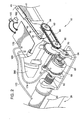
- FIG. 2 is a perspective view of the drive mechanism in accordance with an embodiment of the present invention.
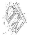
- FIG. 3 is an exploded view of a display retract mechanism in accordance with an embodiment of the present invention.
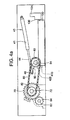
- FIG. 4a is a side view of a display retract mechanism with the display in a retracted position in accordance with an embodiment of the present invention
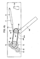
- FIG. 4b is a side view of a display retract mechanism with the display in a partially deployed position in accordance with an embodiment of the present invention
- FIG. 4c is a side view of a display retract mechanism with the display in a deployed position in accordance with an embodiment of the present invention
- FIG. 5 is a perspective view of a display in a deployed position in accordance with an embodiment of the present invention.
- FIG. 6 is an exploded view of a frame for a display for use with a display retract mechanism in accordance with an embodiment of the present invention
- FIG. 7 is a detail of the frame assembly shown in FIG. 6 in accordance with an embodiment of the present invention.
- FIG. 8 is a state diagram showing the logical states of a display retract mechanism in accordance with an embodiment of the present invention.
- a passenger vehicle such as an aircraft
- the underside of an overhead bag bin is preferable to the ceiling of an aisle because many displays are best viewed at close proximity, from a viewing angle perpendicular to the plane of the display.
- a display mounted on the underside of an overhead bag bin may create an obstruction to passengers, for example, by hindering a passenger from entrance to or exit from a seat.
- a device it is desirable for a device to be provided that serves to stow a display in a retracted position when not in use.
- the present invention provides a display retraction mechanism for rotating an overhead display, such as might be mounted underneath a bag bin on an aircraft, between a retracted and a deployed position.
- FIG. 1 An embodiment of a housing for a display retract mechanism is shown in FIG. 1 .
- the housing 10 is comprised of a base 20 and a back cover plate 30.
- the back cover plate 30 is secured to the base 20 by fasteners 32.
- the base 20 comprises a base front 22, a base plate 23, and a base back 26 (the base bay 24 is hidden beneath the back cover plate 30 in FIG. 1 ).
- a gas spring 40 on a gas spring mount 42 is shown.
- Standard video signal connectors (as are recognized by those of skill in the art), including a power connector 160 and a video connector 162 are also shown in FIG. 1 .
- the primary source of energy for rotating the display from a retracted position to a deployed position is provided by the drive mechanism shown, in an embodiment, in FIG. 2 .
- the gas spring 40 comprises a gas spring barrel 41 and a gas spring rod 44.
- the end of the gas spring rod 44 is hingedly connected to a lever arm 90 by its forked end 46.
- the lever arm 90 which serves to transmit force from the gas spring 40 to the pivot shaft 84, is fixed to the pivot shaft 84 by a suitable fixing means, such as a screw, bolt, or epoxy. Other fixing means, such as a weld, are suitable also.
- the lever arm 90 heed not have the specific shape shown in FIG. 2 .
- lever arm 90 for connecting the gas spring to the pivot shaft, thereby transmitting the bias force from the gas spring to the pivot shaft.
- the pivot shield 200 and the base 20 are cut-away in FIG. 2 so that the interior of the housing 10 is visible, including the printed circuit board 170, the cables 172 and 174, and the power connector 160 and video connector 162.
- the energy required to oppose the force of the gas spring is generated by the motor 50 which receives power and control signals from the printed circuit board 170 through a cable 172.
- the motor shaft (hidden behind the mechanical coupler 52 in FIG. 2 ) for the motor 50 is connected to drive shaft 62 through the mechanical coupler 52.
- An electromechanical clutch 60 is provided with power and control signals from the printed circuit board 170 through a cable 174.
- the drive shaft 62 is connected to a first gear 64, and the teeth of the first gear mesh with the teeth of a second gear 70 on a gear shaft 72.
- Also mounted on the gear shaft 72 is a first sprocket 82.
- the first sprocket 82 has teeth provided for holding a chain 80.
- the chain 80 transmits rotational momentum from the gear shaft 72 to the pivot shaft 84, on which a second sprocket 83 is mounted, also having teeth provided for holding the chain 80.
- FIG. 2 Also shown in FIG. 2 is the slip past cable 180 by which the printed circuit board 182 is connected to the display (not shown in FIG. 2 ). Power and data are supplied to the printed circuit board 170 through a power connector 160 and a video connector 162.
- the various components of the display retract mechanism are shown disassembled in FIG. 3 .
- the base 20, which is part of the housing 10, comprises four parts, including a base front 22, a base plate 23, a base bay 24, and a base back 26. All or some of these parts may be coated with a copper epoxy resin, which includes a mixture of copper micro-spheres.
- the copper epoxy resin provides additional EMI shielding by providing a strongly conducting layer between the electronics within the housing 10 and the rest of the passenger vehicle in which the present invention is mounted.
- the base front 22 provides shielding from EMI, as well as a mechanical barrier between the drive mechanism and another device that might exist in a passenger vehicle in which the present invention is mounted.
- the base front 22 is fixed to the base plate 23 with a suitable mechanical device for attachment, such as a screw, bolt, or epoxy.
- the base bay 24 is part of the same physical material as the base plate 23, and constitutes a recess shielded from EMI in which the printed circuit board 182 may be mounted and to which the back cover plate 30 may be partially fixed.
- the gas spring mount 42 is attached beside the base bay 24, fixed directly to the base plate 23 with a suitable mechanical device for attachment, such as a screw, bolt, or epoxy.
- the base back 26 provides a mount for the power connector 160 and video connector 162, and is also fixed to the base plate 23 with a screw, bolt, or epoxy.
- the base back 26 also provides part of the support for the back cover plate 30.
- the pivot shield 200 is also fixed to the base plate 23 with a suitable mechanism for fixing, such as a screw, bolt, or-epoxy, and serves to provide shielding from EMI and prevents interference from another mechanical device with the drive mechanism.
- the drive mechanism including the motor 50, mechanical coupler 52, electromechanical clutch 60, second gear 70, gear shaft 72, and chain 80 are also shown in FIG. 3 .
- the front cover 250 is shown in the retracted position in FIG. 3 .
- FIGS. 4a-c show an embodiment of how the present invention moves a display from the retracted position ( FIG. 4a ) to the deployed position ( FIG. 4c ), with a partially deployed/retracted position in between ( FIG. 4b ).
- first gear 64 On the drive shaft 62 is mounted a first gear 64, with teeth interleaving the teeth of a second gear 70.
- the first gear 64 is fixed to the drive shaft 62, so that, when the motor 50 (not shown in FIG. 4a ) rotates the motor shaft (not shown in FIG. 4a ), the angular momentum of the motor shaft is transmitted through the mechanical coupler 52 (not shown in FIG. 4a ) to the drive shaft 62, turning the first gear 64 in a counter-cloclcwise direction.
- the second gear 70 As the first gear 64 rotates counter-clockwise, the second gear 70 is driven clockwise (in the direction of the arrow shown).
- the second gear 70 is fixed to the gear shaft 72 so that when the second gear 70 turns, it transmits its angular momentum through the gear shaft 72 to the first sprocket 82, which is also fixed to the gear shaft 72.
- a chain 80 Around the teeth of the first sprocket 82 is mounted a chain 80.
- the chain 80 serves to transmit the angular momentum of the clockwise rotating first sprocket 82 to the second sprocket 83, which is mounted on the pivot shaft 84.
- the drive mechanism supplies a torque to the pivot shaft that opposes the force generated by the gas spring 40, which is biased toward the retracted position.
- gearing ratio is about 200:1 (substantially less than the 1000:1 ratios familiar in previous retract mechanisms).
- a solenoid latch 134 with a spike 130 extending toward the frame 100.
- a recess (not shown) in the frame 100 is provided, into which the spike 130 extends.
- the spike 130 when expended into the recess, is capable of maintaining the display in the retracted position.
- the display is moved finally into a fully deployed position, shown in FIG. 4c .
- the latch 134 has withdrawn the spike (130 in FIG. 4a ), which is necessary for the display to be deployed.
- the pivot axis 708 is not expressly shown in FIGS. 4a-c , but is shown as a line passing through the center of the pivot shaft 84, which is perpendicular to the plane of the second sprocket 83 in FIG. 7 .).
- the plastic pin 410 blocks an infrared signal, produced by an infrared transmitter, from hitting an infrared photo sensor 400 when the display first reaches the deployed position.
- the infrared photo sensor 400 begins sending a status control signal to the printed circuit board 182 that indicates to the printed circuit board that the display 120 is now in the deployed position. If, during movement, the display 120 meets a threshold level of force, the motor 50 or the clutch 60 will disengage, and the display 120 will return (using the energy stored in the gas spring 40) to the retracted position. During normal operation, the clutch 60 is engaged while the motor 50 is moving the display 120 from the retracted position to the deployed position. The clutch 60 is also engaged while the display 120 is held in the deployed position.
- FIG. 5 A perspective view of the display 120 as it might appear deployed in a passenger vehicle is shown in FIG. 5 .
- the front cover 250 keeps the display 120 with the frame 100.
- the under side of the housing 10 is also shown in FIG. 5 .
- the FAA has set an additional requirement, colloquially referred to as the "headstrike" requirement, which demands that a display retract when a force surpassing a given threshold force is applied to a display, for example, when the head of a passenger strikes the display upon entrance to or exit from a seat.
- the facility of the present invention for handling this requirement is provided by the electromechanical clutch 60 (shown in FIG. 2 ).
- the present invention is capable of sensing when the threshold force (as specified by the FAA) has been applied to the display, and the display is moved from the deployed position to the retracted position when that force has been applied. Further details on this state of operation are provided in FIG. 8 , and in the description therefor below.
- the same facility is also effected for retracting the display in the event that it should encounter an obstruction while deploying.
- FIG. 6 illustrates the assembly surrounding the display 120 and the frame 100.
- the display 120 and the frame 100 are situated between a back cover 270 and a front cover 250, with a protective screen 260 fixed between the display 120 and the front cover 250.
- FIG. 7 A more detailed view of one corner of the frame 100 is shown in FIG. 7 .
- the frame 100 provides a mechanical support for the cross-hatched cable 180 to interface with the display 120 (not shown in FIG. 7 ).
- the lever ann 90 is fixed with screws 702 to the frame 100.
- the frame 100 is physically connected along the pivot axis (shown as the dotted line 708) to the pivot shaft 84.
- the second sprocket 83, a bolt 710, and a washer 706 are also shown in FIG. 7
- a control circuit including, for example, a microprocessor with memory, is used to keep track of the logical state of the display retract mechanism, and to control its operation.
- the control circuit is provided as part of the printed circuit board 182.
- the logical state of the display retract mechanism is defined by keeping track of the current and previous states of the various components of the system, including the motor 50, the electromechanical clutch 60, the solenoid latch 134, the infrared photo sensor 400, and a clock and increment counter in the control circuit of the printed circuit board 182.
- the control circuitry of the printed circuit board 182 may program the control circuitry of the printed circuit board 182 to maintain the display retract mechanism in the following well-defined logical states.
- the retracted state 800 corresponds to a logical state in which the display is in the retracted position, with the electromechanical clutch 60 disengaged, and the solenoid latch 134 closed (with the spike 130 providing mechanical support for the weight of the frame 100, as shown in FIG. 41).
- the power to the motor 50 and clutch 60 may be off, although power may still be provided to the control circuit on the printed circuit board 182.
- a deploy signal which may be self-generated by the control circuit on the printed circuit board 182, or, alternatively, may be received from an external source in communication with the printed circuit board 170 through the power connector 160 or the video connector 162, the control circuit starts operating the display retract mechanism in the deploying state 810.
- a clock on the printed circuit board 182 begins counting up, and an increment counter on the printed circuit board 182 is initializes to one.
- the solenoid latch 134 is released, retracting the spike 130, the electromechanical clutch 60 is engaged, and the motor 50 is powered.
- the display retract mechanism might appear as shown in FIG. 4b .
- One of several error states may occur in sequence after the deploying state 810.
- the control circuit keeps track of how long the display has been in the deploying state 810. While deploying, the infrared photo sensor 400 will remain open (as shown by the box labeled 815). If the infrared photo sensor 400 does not close before a preset length of time, then the deploy is timed out 845. An obstruction is preventing the device from deploying in a normal length of time.
- the clutch 60 allows the motor 50 to rotate even when the display 120 is prevented from deploying because of an obstruction.
- the display retract mechanism When the deploy is timed out 845, the display retract mechanism will automatically begin retracting.
- the retracting state due to obstruction 840 occurs only when the normal deploying state 810 does not result in a normal deployed state 820, for example, for a reason already discussed, i.e., when the deploy is timed out 845.
- the increment counter is incremented by one. For example, if the display was in the deploying state 810 for the first time since it was in the retracted state 800, then the increment counter will be incremented from one to two when it is put into the retracting due to obstruction state 840. In addition, the clock is reset.
- the display retract mechanism may proceed from the retracting due to obstruction state 840 back to the deploying state 810.
- the increment counter is less than three, and the deploy had timed out 845 on its last deploy attempt, then the display retract mechanism re-enters the deploying state 810.
- the override switch 855 which is provided on the exterior of the device, is activated, then the device re-enters the deploying state 810.
- the override switch 855 allows a human to retake control should the device end up in an ill-defined state.
- the display retract mechanism proceeds directly to the retracted state 800.
- the third case results when the deploying state 810 has timed out for a second time, so that the increment counter now registers three, which results in a retract time out 860. Having returned to the retracted state 800 from the retracting due to obstruction state 840, the display retract mechanism will not begin deploying again until it receives another deploy signal.
- the photo sensor will remain open 815, allowing a control signal to be sent back to the printed circuit board 182, that indicates that the display retract mechanism must remain in the deploying state 810.
- a plastic pin 410 mounted on the front cover 250 in an embodiment of the present invention blocks an infrared signal from an infrared transmitter from being received by the infrared photo sensor 400, i.e., the photo sensor is closed.
- the deployed state 820 is characterized by a state in which the motor 50 is stopped, but the clutch 60 remains engaged, holding the display 100 in the deployed position except in the event of power loss, at which time the display 100 will smoothly retract (using the energy stored in the gas spring 40) into the retracted position.
- the printed circuit board 182 receives a retract signal in the same way that it receives a deploy signal.
- the clutch 60 is disengaged, and the display 100 smoothly retracts in the retracted position (in substantially the same way that it would were the power to the display retract mechanism turned off. Having returned to the retracted position 800, the device is ready to begin the cycle again with another deploy signal.
Landscapes
- Engineering & Computer Science (AREA)
- General Engineering & Computer Science (AREA)
- Theoretical Computer Science (AREA)
- Aviation & Aerospace Engineering (AREA)
- Mechanical Engineering (AREA)
- Computer Hardware Design (AREA)
- Human Computer Interaction (AREA)
- Physics & Mathematics (AREA)
- General Physics & Mathematics (AREA)
- Devices For Indicating Variable Information By Combining Individual Elements (AREA)
- Fittings On The Vehicle Exterior For Carrying Loads, And Devices For Holding Or Mounting Articles (AREA)
- Mobile Radio Communication Systems (AREA)
Abstract
Description
- The invention pertains to mechanical devices for use in moving an overhead display. Specifically, the invention is a mechanism for deploying and retracting an overhead display. Document
US-B1-6,256,078 discloses such a mechanism. - In a passenger vehicle it may be desirable for a display, such as a video display, to be hidden when not in use. A mechanical device is necessary for deploying and retracting the display. In most environments, the mechanical device may also be subject to additional constraints such as size, weight, and power constraints. In some environments there may be additional constraints. For example, in an aircraft environment a mechanical device used for deploying and retracting an overhead display must automatically retract in the event of power loss to the cabin, or in the event that the head of a passenger strikes the display.
- Traditional methods for deploying and retracting displays in passenger vehicles include the use of linkage arms extending from a motor to a monitor to rotate the monitor to a pre-set viewing position. A slip clutch between the monitor and the motor allows for the display to retract when struck from a certain direction. A mechanical spring stores the energy for automatic retract of the monitor in an emergency situation resulting in the loss of power.
- Displays have been deployed and retracted by mechanisms linking the motor to the monitor by gears. The gear and motor linkage approach wears at the pivot points and the monitor vibrates during transportation making viewing difficult. Vibrations in the display during transport may be reduced with tighter tolerance gears, but tighter tolerance gears would be ineffective from both weight and cost perspectives, and gear tolerance will be lost with time and use.
- Vibrations in the display have also been reduced by using a brake and by driving a motor in reverse. The brake damps the vibrations transmitted to a display from a motor while the display is deploying, and maintains the display in a deployed position. The display is moved from the deployed to a retracted position by first releasing the brake. Vibrations are damped while the display is retracting by driving the motor in reverse. The energy necessary to move the display from the deployed to the retracted position is generally stored in a spring. Since driving the motor in reverse increases resistance to the movement of the display, a larger spring is required when this technique is used for damping vibrations. Often, larger springs create noisy whines when they are wound and unwound in this way.
- In some passenger vehicles, the electromagnetic interference ("EMI") generated by a display may also be an issue. Power and video distribution systems use single stranded wires or combinations of flex and single stranded wires to distribute power. The power is distributed between the video board in the monitor assembly and the main chassis. The length of the wires, and the high frequencies of the video signals being transmitted through them, together act like an antenna. In general, any mechanical device designed for deploying and retracting an overhead display must attempt to mitigate the effects of EMI on the video signal transmitted to the display.
- The invention provides a display retract mechanism for moving a display from a deployed position to a retracted position. The display retract mechanism includes a frame adapted for holding a display, a pivot shaft, a lever arm fixed to the pivot shaft, a gas spring, and a drive mechanism. The pivot shaft is attached to the frame along a pivot axis, and the pivot shaft rotates around the pivot axis from the retracted position to the deployed position and back. The frame, which is adapted for holding the display, is attached to the pivot shaft along the pivot axis so that as the pivot shaft rotates around the pivot axis the frame, which holds the display, moves from the retracted position to the deployed position. The gas spring is hingedly connected to the lever arm, which is in turn fixed to the pivot shaft. The arrangement allows for the display to be retracted when power to the drive mechanism is off.
- The present invention also provides a facility for detecting when the monitor is in a retracted position. In an embodiment, there is provided an infrared transmitter for supplying an infrared signal. As will be recognized by those of skill in the art, other types of transducers, including ultrasonic, electro-optic, or electromechanical are also possible. The detector of the present invention could be any one of a variety of such transducers. The infrared signal is received by an infrared sensor, which produces a status signal when the infrared signal is received. When the display is in the retracted position, a pin mounted on the frame blocks the infrared signal, preventing the infrared signal from reaching the infrared sensor. The status signal produced by the infrared signal is supplied to a printed circuit board, where it is useful for producing a control signal. The printed circuit board is optionally connected with power and video connectors. The EMI with video signals sent between the printed circuit board and the display is advantageously reduced through the use of a cross-hatched slip past cable.
- In an embodiment of the present invention, the drive mechanism includes a motor for driving a motor shaft; a drive shaft; a mechanical coupler for joining the motor shaft to the drive shaft; a first gear on the drive shaft; a second gear on a gear shaft, the first gear in mechanical contact with the second gear; a first sprocket attached to the gear shaft; a second sprocket attached to the pivot shaft; a chain mounted on both the first sprocket and the second sprocket, whereby the torque from the gear shaft is transmitted to the pivot shaft; a motor controller card for producing a motor drive signal in response to the control signal from the printed circuit board; and a power supply for supplying a power to the display retract mechanism. Optionally, an electromechanical clutch mechanism may be provided to the drive mechanism for selectively engaging and disengaging the drive mechanism. In addition, a solenoid latch optionally may be provided to the display retract mechanism for locking the frame into the retracted position. The gear ratio of the first gear to the second gear is about 200 to 1. The relatively low gear ratio is an advantage of the present invention.
- The display retract mechanism may optionally provide a housing, to which the pivot shaft may be mounted. The housing is adaptable for receiving the frame when the display is in the retracted position. The housing is not necessary to the present invention; rather, it is a convenience allowing for simpler installation and de-installation of the device, providing a single mechanical structure to which some parts of the device may be attached. It will be understood by those of skill in the art that the housing is not necessary to the function of the present invention.
- In a preferred embodiment of the present invention, the frame and the housing are fabricated from a material that is mechanically strong, heat resistant, and burns with low toxicity. The frame and the housing may be fabricated from a material selected from the group consisting of polyetherimide or polyphenylsulfone. In addition, the housing may be coated with a copper epoxy resin, which includes a mixture of copper micro-spheres. EMI produced by the display retract mechanism is advantageously reduced through the use of the copper epoxy resin.
- In addition, the present invention provides a method for moving a display from a deployed position to a retracted position. The method includes the following steps: holding the display in a frame; rotating a pivot shaft around a pivot axis, the frame attached to the pivot shaft along the pivot axis; fixing a lever arm to the pivot shaft, the lever arm compressing a gas spring as the pivot shaft is rotated around the pivot axis from the retracted position to the deployed position; and supplying torque to the pivot shaft for rotating the pivot shaft from the retracted to the deployed position with the drive mechanism. The method may optionally include the further steps of generating an infrared signal; receiving the infrared signal in order to produce a status signal; blocking the infrared signal with a pin in order to prevent the receiving of the infrared signal; and processing the status signal in order to produce a controlled signal. In an optional final step, the pivot shaft may be attached to a housing, the housing adapted for receiving the frame when the display is the retracted position.
- The power and video distribution system of the present invention may combine all power and video cables to the LCD in a cross-hatched, slip-past, flexible cable. The cable is chosen for its ability to withstand multiple flex cycles, and for its ability to shield from EMI.
- The display retract mechanism also uses a gas spring to retract the monitor. The gas spring provides a near linear force curve for the range of actuation, requiring less power from the drive mechanism, and allowing for smoother operation of the display retract mechanism as a whole. The combination of the clutch, motor, and gas spring of the present invention provides a quieter display retract mechanism than has been conventionally available.
- The foregoing and other objects, advantages, and features of the present invention will be apparent from the following detailed description and the accompanying drawings, in which:
-
FIG. 1 is a perspective view of a housing for a display retract mechanism in accordance with an embodiment of the present invention; -
FIG. 2 is a perspective view of the drive mechanism in accordance with an embodiment of the present invention; -
FIG. 3 is an exploded view of a display retract mechanism in accordance with an embodiment of the present invention; -
FIG. 4a is a side view of a display retract mechanism with the display in a retracted position in accordance with an embodiment of the present invention; -
FIG. 4b is a side view of a display retract mechanism with the display in a partially deployed position in accordance with an embodiment of the present invention; -
FIG. 4c is a side view of a display retract mechanism with the display in a deployed position in accordance with an embodiment of the present invention; -
FIG. 5 is a perspective view of a display in a deployed position in accordance with an embodiment of the present invention; -
FIG. 6 is an exploded view of a frame for a display for use with a display retract mechanism in accordance with an embodiment of the present invention; -
FIG. 7 is a detail of the frame assembly shown inFIG. 6 in accordance with an embodiment of the present invention; and -
FIG. 8 is a state diagram showing the logical states of a display retract mechanism in accordance with an embodiment of the present invention. - In a passenger vehicle, such as an aircraft, it is desirable for overhead displays to be mounted in close proximity to a passenger. The underside of an overhead bag bin is preferable to the ceiling of an aisle because many displays are best viewed at close proximity, from a viewing angle perpendicular to the plane of the display. However, a display mounted on the underside of an overhead bag bin may create an obstruction to passengers, for example, by hindering a passenger from entrance to or exit from a seat. Hence, it is desirable for a device to be provided that serves to stow a display in a retracted position when not in use. The present invention provides a display retraction mechanism for rotating an overhead display, such as might be mounted underneath a bag bin on an aircraft, between a retracted and a deployed position.
- The advantages of the present invention are obtained in part through the use of a chain drive with a low gearing ratio, a gas spring for biasing the display towards the retracted position, an infrared transmit and receive sensor, an electromagnetic clutch, and a housing and cables designed to minimize EMI.
- Although it is not necessary to the method or system of the present invention, it is desirable for a
housing 10 to be provided to the present invention. An embodiment of a housing for a display retract mechanism is shown inFIG. 1 . Thehousing 10 is comprised of abase 20 and aback cover plate 30. Theback cover plate 30 is secured to thebase 20 byfasteners 32. Thebase 20 comprises abase front 22, abase plate 23, and a base back 26 (thebase bay 24 is hidden beneath theback cover plate 30 inFIG. 1 ). Agas spring 40 on agas spring mount 42 is shown. Standard video signal connectors (as are recognized by those of skill in the art), including apower connector 160 and avideo connector 162 are also shown inFIG. 1 . - The primary source of energy for rotating the display from a retracted position to a deployed position is provided by the drive mechanism shown, in an embodiment, in
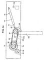
FIG. 2 . Thegas spring 40 comprises agas spring barrel 41 and agas spring rod 44. The end of thegas spring rod 44 is hingedly connected to alever arm 90 by its forkedend 46. Thelever arm 90, which serves to transmit force from thegas spring 40 to thepivot shaft 84, is fixed to thepivot shaft 84 by a suitable fixing means, such as a screw, bolt, or epoxy. Other fixing means, such as a weld, are suitable also. As will be understood by those of ordinary skill in the art, thelever arm 90 heed not have the specific shape shown inFIG. 2 . Other mechanical means, for example, a lever arm of different shape, a linkage arm, or a hook, may be used as alever arm 90 for connecting the gas spring to the pivot shaft, thereby transmitting the bias force from the gas spring to the pivot shaft. Thepivot shield 200 and the base 20 are cut-away inFIG. 2 so that the interior of thehousing 10 is visible, including the printedcircuit board 170, thecables power connector 160 andvideo connector 162. - The energy required to oppose the force of the gas spring is generated by the
motor 50 which receives power and control signals from the printedcircuit board 170 through acable 172. The motor shaft (hidden behind themechanical coupler 52 inFIG. 2 ) for themotor 50 is connected to driveshaft 62 through themechanical coupler 52. An electromechanical clutch 60 is provided with power and control signals from the printedcircuit board 170 through acable 174. Thedrive shaft 62 is connected to afirst gear 64, and the teeth of the first gear mesh with the teeth of asecond gear 70 on agear shaft 72. Also mounted on thegear shaft 72 is afirst sprocket 82. Thefirst sprocket 82 has teeth provided for holding achain 80. Thechain 80 transmits rotational momentum from thegear shaft 72 to thepivot shaft 84, on which asecond sprocket 83 is mounted, also having teeth provided for holding thechain 80. - Also shown in
FIG. 2 is the slip pastcable 180 by which the printedcircuit board 182 is connected to the display (not shown inFIG. 2 ). Power and data are supplied to the printedcircuit board 170 through apower connector 160 and avideo connector 162. - The various components of the display retract mechanism, according to an embodiment of the present invention, are shown disassembled in
FIG. 3 . Thebase 20, which is part of thehousing 10, comprises four parts, including abase front 22, abase plate 23, abase bay 24, and a base back 26. All or some of these parts may be coated with a copper epoxy resin, which includes a mixture of copper micro-spheres. The copper epoxy resin provides additional EMI shielding by providing a strongly conducting layer between the electronics within thehousing 10 and the rest of the passenger vehicle in which the present invention is mounted. - The
base front 22 provides shielding from EMI, as well as a mechanical barrier between the drive mechanism and another device that might exist in a passenger vehicle in which the present invention is mounted. Thebase front 22 is fixed to thebase plate 23 with a suitable mechanical device for attachment, such as a screw, bolt, or epoxy. - The
base bay 24 is part of the same physical material as thebase plate 23, and constitutes a recess shielded from EMI in which the printedcircuit board 182 may be mounted and to which theback cover plate 30 may be partially fixed. In the embodiment of the invention shown inFIG. 3 , thegas spring mount 42 is attached beside thebase bay 24, fixed directly to thebase plate 23 with a suitable mechanical device for attachment, such as a screw, bolt, or epoxy. The base back 26 provides a mount for thepower connector 160 andvideo connector 162, and is also fixed to thebase plate 23 with a screw, bolt, or epoxy. The base back 26 also provides part of the support for theback cover plate 30. - The
pivot shield 200 is also fixed to thebase plate 23 with a suitable mechanism for fixing, such as a screw, bolt, or-epoxy, and serves to provide shielding from EMI and prevents interference from another mechanical device with the drive mechanism. The drive mechanism, including themotor 50,mechanical coupler 52, electromechanical clutch 60,second gear 70,gear shaft 72, andchain 80 are also shown inFIG. 3 . Finally, thefront cover 250 is shown in the retracted position inFIG. 3 . - The series of
FIGS. 4a-c show an embodiment of how the present invention moves a display from the retracted position (FIG. 4a ) to the deployed position (FIG. 4c ), with a partially deployed/retracted position in between (FIG. 4b ). - On the
drive shaft 62 is mounted afirst gear 64, with teeth interleaving the teeth of asecond gear 70. Thefirst gear 64, is fixed to thedrive shaft 62, so that, when the motor 50 (not shown inFIG. 4a ) rotates the motor shaft (not shown inFIG. 4a ), the angular momentum of the motor shaft is transmitted through the mechanical coupler 52 (not shown inFIG. 4a ) to thedrive shaft 62, turning thefirst gear 64 in a counter-cloclcwise direction. As thefirst gear 64 rotates counter-clockwise, thesecond gear 70 is driven clockwise (in the direction of the arrow shown). Thesecond gear 70 is fixed to thegear shaft 72 so that when thesecond gear 70 turns, it transmits its angular momentum through thegear shaft 72 to thefirst sprocket 82, which is also fixed to thegear shaft 72. Around the teeth of thefirst sprocket 82 is mounted achain 80. Thechain 80 serves to transmit the angular momentum of the clockwise rotatingfirst sprocket 82 to thesecond sprocket 83, which is mounted on thepivot shaft 84. Hence, the drive mechanism supplies a torque to the pivot shaft that opposes the force generated by thegas spring 40, which is biased toward the retracted position. The choice ofmotor 50,first gear 64, andsecond gear 70 must be made considering the strength of the force generated by thegas spring 40, which will vary with embodiments of the present invention. Such a choice could be made readily by one of ordinary skill in the art. In the presently preferred embodiment of the invention, the gearing ratio is about 200:1 (substantially less than the 1000:1 ratios familiar in previous retract mechanisms). - Also shown in
Figure 4a is asolenoid latch 134, with aspike 130 extending toward theframe 100. A recess (not shown) in theframe 100 is provided, into which thespike 130 extends. Thespike 130, when expended into the recess, is capable of maintaining the display in the retracted position. - As the
pivot shaft 84 is rotated by the drive mechanism in the clockwise direction, thelever arm 90, which is attached to the pivot shaft either directly or indirectly, through thesecond sprocket 83, is rotated. When thelever arm 90 rotates, the gas spring rod 44 (hingedly connected to thelever arm 90 by its forked end 46) is pushed into thegas spring barrel 42. Hence, theframe 100, which is fixed to the other end of thelever arm 90, moves into a partially deployed position, as shown inFIG. 4b . Note that the main differences betweenFIG. 4a andFIG. 4b are the shown length of the gas spring rod 44 (shorter inFIG. 4b because thegas spring rod 44 has been pushed into the gas spring barrel 42) and the position of theframe 100. As the same motion continues, the display is moved finally into a fully deployed position, shown inFIG. 4c . Note also that inFIG. 4b and4c thelatch 134 has withdrawn the spike (130 inFIG. 4a ), which is necessary for the display to be deployed. - A
plastic pin 410 disposed on thefront cover 250 of the frame 100 (shown inFIGS. 4a-c ) on an edge of theframe 100 near thepivot axis 708. (Thepivot axis 708 is not expressly shown inFIGS. 4a-c , but is shown as a line passing through the center of thepivot shaft 84, which is perpendicular to the plane of thesecond sprocket 83 inFIG. 7 .). Theplastic pin 410 blocks an infrared signal, produced by an infrared transmitter, from hitting aninfrared photo sensor 400 when the display first reaches the deployed position. Theinfrared photo sensor 400, not receiving the infrared signal anymore, begins sending a status control signal to the printedcircuit board 182 that indicates to the printed circuit board that thedisplay 120 is now in the deployed position. If, during movement, thedisplay 120 meets a threshold level of force, themotor 50 or the clutch 60 will disengage, and thedisplay 120 will return (using the energy stored in the gas spring 40) to the retracted position. During normal operation, the clutch 60 is engaged while themotor 50 is moving thedisplay 120 from the retracted position to the deployed position. The clutch 60 is also engaged while thedisplay 120 is held in the deployed position. - A perspective view of the
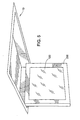
display 120 as it might appear deployed in a passenger vehicle is shown inFIG. 5 . Thefront cover 250 keeps thedisplay 120 with theframe 100. The under side of thehousing 10 is also shown inFIG. 5 . - In some environments, for example, in aircraft environments, there are constraints on the manner in which a display retract mechanism may operate. In the United States of America, the Federal Aviation Administration (FAA) requires that all under-bag-bin displays retract automatically in the event of power loss to the cabin during flight. As would be obvious to one of ordinary skill in the art, this requirement is naturally met by the device as disclosed and explained in connection with
FIGS. 1-5 . When power is no longer supplied to the present invention, the clutch 60 de-energizes and decouples themotor 50 from thegas spring 40, thegas spring 40 then smoothly retracts the display into a retracted position. - The FAA has set an additional requirement, colloquially referred to as the "headstrike" requirement, which demands that a display retract when a force surpassing a given threshold force is applied to a display, for example, when the head of a passenger strikes the display upon entrance to or exit from a seat. The facility of the present invention for handling this requirement is provided by the electromechanical clutch 60 (shown in
FIG. 2 ). In combination with the printed circuit board 182 (to which theelectromechanical clutch 60 is connected by a bundled power and data cable 174), the present invention is capable of sensing when the threshold force (as specified by the FAA) has been applied to the display, and the display is moved from the deployed position to the retracted position when that force has been applied. Further details on this state of operation are provided inFIG. 8 , and in the description therefor below. The same facility is also effected for retracting the display in the event that it should encounter an obstruction while deploying. -
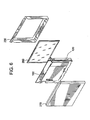
FIG. 6 illustrates the assembly surrounding thedisplay 120 and theframe 100. Thedisplay 120 and theframe 100 are situated between aback cover 270 and afront cover 250, with aprotective screen 260 fixed between thedisplay 120 and thefront cover 250. - A more detailed view of one corner of the
frame 100 is shown inFIG. 7 . Theframe 100 provides a mechanical support for thecross-hatched cable 180 to interface with the display 120 (not shown inFIG. 7 ). In addition, thelever ann 90 is fixed withscrews 702 to theframe 100. Ahinge 704, withseveral washers 706, hingedly connects the forkedend 46 of the gas spring 40 (not shown inFIG. 7 ) to thelever arm 90. In addition, theframe 100 is physically connected along the pivot axis (shown as the dotted line 708) to thepivot shaft 84. Thesecond sprocket 83, abolt 710, and awasher 706 are also shown inFIG. 7 - A control circuit, including, for example, a microprocessor with memory, is used to keep track of the logical state of the display retract mechanism, and to control its operation. In the present invention, the control circuit is provided as part of the printed
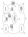
circuit board 182. The logical state of the display retract mechanism is defined by keeping track of the current and previous states of the various components of the system, including themotor 50, the electromechanical clutch 60, thesolenoid latch 134, theinfrared photo sensor 400, and a clock and increment counter in the control circuit of the printedcircuit board 182. Using the feedback and control provided by the foregoing, one of ordinary skill in the art may program the control circuitry of the printedcircuit board 182 to maintain the display retract mechanism in the following well-defined logical states. - The retracted
state 800 corresponds to a logical state in which the display is in the retracted position, with the electromechanical clutch 60 disengaged, and thesolenoid latch 134 closed (with thespike 130 providing mechanical support for the weight of theframe 100, as shown in FIG. 41). The power to themotor 50 and clutch 60 may be off, although power may still be provided to the control circuit on the printedcircuit board 182. - On receiving a deploy signal, which may be self-generated by the control circuit on the printed
circuit board 182, or, alternatively, may be received from an external source in communication with the printedcircuit board 170 through thepower connector 160 or thevideo connector 162, the control circuit starts operating the display retract mechanism in the deployingstate 810. In the deployingstate 810, a clock on the printedcircuit board 182 begins counting up, and an increment counter on the printedcircuit board 182 is initializes to one. Thesolenoid latch 134 is released, retracting thespike 130, theelectromechanical clutch 60 is engaged, and themotor 50 is powered. In the deployingstate 810, the display retract mechanism might appear as shown inFIG. 4b . - One of several error states may occur in sequence after the deploying
state 810. Using the clock on the printedcircuit board 182, the control circuit keeps track of how long the display has been in the deployingstate 810. While deploying, theinfrared photo sensor 400 will remain open (as shown by the box labeled 815). If theinfrared photo sensor 400 does not close before a preset length of time, then the deploy is timed out 845. An obstruction is preventing the device from deploying in a normal length of time. The clutch 60 allows themotor 50 to rotate even when thedisplay 120 is prevented from deploying because of an obstruction. - When the deploy is timed out 845, the display retract mechanism will automatically begin retracting. The retracting state due to
obstruction 840 occurs only when the normal deployingstate 810 does not result in a normal deployedstate 820, for example, for a reason already discussed, i.e., when the deploy is timed out 845. - When the deploying
state 810 moves into the retracting due toobstruction state 840, the increment counter is incremented by one. For example, if the display was in the deployingstate 810 for the first time since it was in the retractedstate 800, then the increment counter will be incremented from one to two when it is put into the retracting due toobstruction state 840. In addition, the clock is reset. - Three different cases are possible for what logical state will follow the retracting due to obstruction state. In two cases, the display retract mechanism may proceed from the retracting due to
obstruction state 840 back to the deployingstate 810. In the first case, if the increment counter is less than three, and the deploy had timed out 845 on its last deploy attempt, then the display retract mechanism re-enters the deployingstate 810. In the second case, if theoverride switch 855, which is provided on the exterior of the device, is activated, then the device re-enters the deployingstate 810. Theoverride switch 855 allows a human to retake control should the device end up in an ill-defined state. In the third case, the display retract mechanism proceeds directly to the retractedstate 800. The third case results when the deployingstate 810 has timed out for a second time, so that the increment counter now registers three, which results in a retract time out 860. Having returned to the retractedstate 800 from the retracting due toobstruction state 840, the display retract mechanism will not begin deploying again until it receives another deploy signal. - Returning to a description of the normal states of operation, there is shown in
FIG. 8 how the display retract mechanism may progress from a deployingstate 810 to a deployed (photo sensor = closed) state 220. During the deploying, the photo sensor will remain open 815, allowing a control signal to be sent back to the printedcircuit board 182, that indicates that the display retract mechanism must remain in the deployingstate 810. After thedisplay 100 has reached the deployed position, a plastic pin 410 (mounted on thefront cover 250 in an embodiment of the present invention) blocks an infrared signal from an infrared transmitter from being received by theinfrared photo sensor 400, i.e., the photo sensor is closed. Hence, the control signal sent to the printedcircuit board 182 now indicates that thedisplay 100 is in the deployed position. The deployedstate 820 is characterized by a state in which themotor 50 is stopped, but the clutch 60 remains engaged, holding thedisplay 100 in the deployed position except in the event of power loss, at which time thedisplay 100 will smoothly retract (using the energy stored in the gas spring 40) into the retracted position. - In an embodiment, the printed
circuit board 182 receives a retract signal in the same way that it receives a deploy signal. Upon receipt of a retract signal, the clutch 60 is disengaged, and thedisplay 100 smoothly retracts in the retracted position (in substantially the same way that it would were the power to the display retract mechanism turned off. Having returned to the retractedposition 800, the device is ready to begin the cycle again with another deploy signal. - The use of the terms "a" and "an" and "the" and similar referents in the context of describing the invention (especially in the context of the following claims) are to be construed to cover both the singular and the plural, unless otherwise indicated herein or clearly contradicted by context. Recitation of ranges of values herein are merely intended to serve as a shorthand method of referring individually to each separate value falling within the range, unless otherwise indicated herein, and each separate value is incorporated into the specification as if it were individually recited herein. All methods described herein can be performed in any suitable order unless otherwise indicated herein or otherwise clearly contradicted by context. The use of any and all examples, or exemplary language (e.g., "such as") provided herein, is intended merely to better illuminate the invention and does not pose a limitation on the scope of the invention unless otherwise claimed. No language in the specification should be construed as indicating any non-claimed element as essential to the practice of the invention.
- Preferred embodiments of this invention are described herein, including the best mode known to the inventors for carrying out the invention. Of course, variations of those preferred embodiments will become apparent to those of ordinary skill in the art upon reading the foregoing description. The inventors expect skilled artisans to employ such variations as appropriate, and the inventors intend for the invention to be practiced otherwise than as specifically described herein. Accordingly, this invention includes all modifications and equivalents of the subject matter recited in the claims appended hereto as permitted by applicable law. Moreover, any combination of the above-described elements in all possible variations thereof is encompassed by the invention unless otherwise indicated herein or otherwise clearly contradicted by context.
Claims (21)
- A display retract mechanism for moving a display from a deployed position to a retracted position, comprising:a frame (100) adapted for holding a display;a pivot shaft (84) defining a pivot axis, the pivot shaft rotatable around the pivot axis from the retracted position to the deployed position;a lever arm (90) fixed to the pivot shaft;a gas spring (40) biased toward the retracted position, the gas spring hingedly connected to the lever arm; anda drive mechanism for rotating the pivot shaft around the pivot axis from the retracted to the deployed position.
- The display retract mechanism of claim 1, further comprising:a detector for determining when the frame is in the retracted position.
- The display retract mechanism of claim 1 or 2, wherein a cross-hatched slip past cable connects the display to a printed circuit board.
- The display retract mechanism of claim 2 3, wherein the printed circuit board is connected to a power connector.
- The display retract mechanism of claim 3 or 4, wherein the printed circuit board is connected to a video connector.
- The display retract mechanism as claimed in any one of the preceding claims, the drive mechanism comprising:a motor for driving a motor shaft;a drive shaft;a mechanical coupler for joining the motor shaft to the drive shaft;a first gear on the drive shaft;a second gear on a gear shaft, the first gear in mechanical contact with the second gear;a first sprocket attached to the gear shaft;a second sprocket attached to the pivot shaft;a chain mounted on both the first sprocket and the second sprocket, whereby the torque from the gear shaft is transmitted to the pivot shaft;a motor controller card for producing a motor drive signal in response to the control signal from the printed circuit board; anda power supply for supplying power to the display retract mechanism.
- The display retract mechanism as claimed in any one of the preceding claims, further comprising:a clutch mechanism for selectively engaging and disengaging the drive mechanism.
- The display retract mechanism as claimed in any one of the preceding claims, further comprising:a latch for locking the frame into the retracted position.
- The display retract mechanism of claim 6, wherein the gear ratio of the first gear to the second gear is about 200:1.
- The display retract mechanism as claimed in any one of the preceding claims, further comprising:a housing to which the pivot shaft is mounted, the housing adaptable for receiving the frame in the retracted position.
- The display retract mechanism of claim 10, wherein the frame and the housing are fabricated from a material selected from the group consisting of polyetherimide or polyphenylsulfone.
- The display retract mechanism of claim 10 or 11, wherein the housing is coated with a copper epoxy resin.
- The display retract mechanism as claimed in any one of claims 10 to 12,
wherein a motor controller card, a power supply, and a printed circuit board are mounted to the housing. - The display retract mechanism as claimed in any one of the preceding claims, further comprising:detector means for detecting when the display is in the retracted position,wherein the frame is attached to the pivot shaft along the pivot axis, and the drive means supplies torque to the pivot shaft, in order to rotate the frame around the pivot axis from the retracted position to the deployed position.
- The display retract mechanism of claim 7, wherein the clutch mechanism includes an electromechanical clutch.
- The display retract mechanism as claimed in any one of the preceding claims, wherein the gas spring substantially freely moves the pivot shaft from the deployed position toward the retracted position when the drive mechanism releases the pivot shaft.
- A method for moving a display from a deployed position to a retracted position, the method comprising the steps of:holding the display in a frame (100);rotating a pivot shaft (84) around a pivot axis, the frame attached to the pivot shaft along the pivot axis;fixing a lever arm (90) to the pivot shaft, the lever arm compressing a gas spring (40) as the pivot shaft is rotated around the pivot axis from the retracted position to the deployed position; andsupplying torque to the pivot shaft for rotating the pivot shaft from the retracted to the deployed position with a drive mechanism.
- The method of claim 17, further comprising the steps of:generating a detector signal;receiving the detector signal in order to produce a status signal;blocking the detector signal with a pin in order to prevent the receiving of the detector signal; andprocessing the status signal in order to produce a control signal.
- The method of claim 18, further comprising the step of:attaching the pivot shaft to a housing, the housing adapted for receiving the frame when the display is in the retracted position.
- The method as claimed in any one of claims 17 to 19, further comprising the step of:using an electromechanical clutch to hold the display in place.
- The method as claimed in any one of claims 17 to 20, further comprising the step of:allowing the gas spring to substantially freely move the pivot shaft from the deployed position to the retracted position when the drive mechanism releases the pivot shaft.
Priority Applications (1)
| Application Number | Priority Date | Filing Date | Title |
|---|---|---|---|
| EP11175321A EP2392498A3 (en) | 2002-10-17 | 2003-10-14 | Display retract mechanism |
Applications Claiming Priority (3)
| Application Number | Priority Date | Filing Date | Title |
|---|---|---|---|
| US10/273,237 US7042528B2 (en) | 2002-10-17 | 2002-10-17 | Display retract mechanism |
| US273237 | 2002-10-17 | ||
| PCT/US2003/032443 WO2004036531A2 (en) | 2002-10-17 | 2003-10-14 | Display retract mechanism |
Publications (3)
| Publication Number | Publication Date |
|---|---|
| EP1552688A2 EP1552688A2 (en) | 2005-07-13 |
| EP1552688A4 EP1552688A4 (en) | 2006-12-13 |
| EP1552688B1 true EP1552688B1 (en) | 2011-07-27 |
Family
ID=32092755
Family Applications (2)
| Application Number | Title | Priority Date | Filing Date |
|---|---|---|---|
| EP03774812A Expired - Lifetime EP1552688B1 (en) | 2002-10-17 | 2003-10-14 | Display retract mechanism |
| EP11175321A Withdrawn EP2392498A3 (en) | 2002-10-17 | 2003-10-14 | Display retract mechanism |
Family Applications After (1)
| Application Number | Title | Priority Date | Filing Date |
|---|---|---|---|
| EP11175321A Withdrawn EP2392498A3 (en) | 2002-10-17 | 2003-10-14 | Display retract mechanism |
Country Status (7)
| Country | Link |
|---|---|
| US (3) | US7042528B2 (en) |
| EP (2) | EP1552688B1 (en) |
| JP (2) | JP2006507172A (en) |
| AT (1) | ATE517785T1 (en) |
| AU (1) | AU2003282811A1 (en) |
| CA (1) | CA2501531A1 (en) |
| WO (1) | WO2004036531A2 (en) |
Families Citing this family (54)
| Publication number | Priority date | Publication date | Assignee | Title |
|---|---|---|---|---|
| US7042528B2 (en) * | 2002-10-17 | 2006-05-09 | Thales Avionics, Inc. | Display retract mechanism |
| US7296774B2 (en) * | 2004-01-02 | 2007-11-20 | Clo Systems, Llc | Viewing angle adjustment system for a monitor |
| DE102004024996A1 (en) * | 2004-05-21 | 2005-12-08 | Robert Bosch Gmbh | Fold-out monitor |
| US7425889B2 (en) * | 2005-05-06 | 2008-09-16 | Delphi Technologies, Inc. | Vehicle turning assist system and method |
| DE112006000764B4 (en) * | 2005-05-26 | 2012-03-01 | Mitsubishi Electric Corp. | display device |
| EP1890055B1 (en) * | 2005-05-27 | 2011-03-30 | Panasonic Corporation | Power transmission device, and display device and display panel pedestal that have the power transmission device |
| US7333009B2 (en) * | 2005-06-10 | 2008-02-19 | Audiovox Corporation | Overhead display device for a vehicle |
| US20070028262A1 (en) * | 2005-07-29 | 2007-02-01 | Zermatt Systems, Inc. | Virtual discovery of content available to a device |
| US20070097893A1 (en) * | 2005-11-03 | 2007-05-03 | International Business Machines Corporation | Method of delivering personalized streaming content via satellite radio |
| US7467001B2 (en) * | 2005-12-30 | 2008-12-16 | Inventec Corporation | Handheld electronic device having a replaceable glass cover for LCD thereof |
| KR100801251B1 (en) * | 2006-04-13 | 2008-02-04 | 삼성전기주식회사 | Extension apparatus of display |
| KR100815316B1 (en) * | 2006-05-15 | 2008-03-19 | 삼성전기주식회사 | Opening and closing device for a note book computer |
| US8184974B2 (en) | 2006-09-11 | 2012-05-22 | Lumexis Corporation | Fiber-to-the-seat (FTTS) fiber distribution system |
| US20080159556A1 (en) * | 2006-12-29 | 2008-07-03 | Aaron Ambrose | Method to control entertainment display device |
| DE102007001578B4 (en) * | 2007-01-10 | 2018-10-11 | Diehl Aviation Laupheim Gmbh | Backlit aircraft interior component |
| US8363170B2 (en) * | 2007-06-14 | 2013-01-29 | Panasonic Automotive Systems Company Of America, Division Of Panasonic Corporation Of North America | Dual display multi-modal vehicle infotainment system |
| DE102007041342A1 (en) * | 2007-08-31 | 2009-03-05 | Continental Automotive Gmbh | driving means |
| US7661642B2 (en) * | 2007-10-11 | 2010-02-16 | Clo Systems | Motorized mount to pivot a monitor |
| DE102007050788A1 (en) * | 2007-10-24 | 2009-04-30 | Fischer Automotive Systems Gmbh & Co. Kg | Screen holding device and driving motor arrangement, has translation element intended to transfer force from driving motor to drive element, where force produced from driving motor is transferable to drive element |
| US20090109352A1 (en) * | 2007-10-29 | 2009-04-30 | Lewis Brian E | Apparatus, system and method for mounting a display screen in a vehicular compartment |
| FR2929202B1 (en) * | 2008-03-31 | 2015-01-02 | Vision Systems Aeronautics | DEVICE FOR DISSEMINATING VISUAL INFORMATION OR AUDIOVISUAL CONTENT. |
| JP2010032316A (en) * | 2008-07-28 | 2010-02-12 | Pioneer Electronic Corp | Device, method, and program for controlling display means |
| ES2715850T3 (en) | 2009-08-06 | 2019-06-06 | Global Eagle Entertainment Inc | In-flight system of interconnection in series fiber network to the seat |
| JPWO2011016093A1 (en) * | 2009-08-07 | 2013-01-10 | 三菱電機株式会社 | In-vehicle display device |
| US8424045B2 (en) | 2009-08-14 | 2013-04-16 | Lumexis Corporation | Video display unit docking assembly for fiber-to-the-screen inflight entertainment system |
| US8416698B2 (en) | 2009-08-20 | 2013-04-09 | Lumexis Corporation | Serial networking fiber optic inflight entertainment system network configuration |
| US8636182B1 (en) * | 2009-11-09 | 2014-01-28 | Joel Gordon | Pickup truck storage device |
| DE102009057017B4 (en) * | 2009-12-04 | 2014-08-07 | Airbus Operations Gmbh | Display for an aircraft |
| DE102010011893A1 (en) * | 2010-03-18 | 2011-11-17 | Brose Fahrzeugteile Gmbh & Co. Kommanditgesellschaft, Coburg | Picture screen adjustment device for motor car, has positioning mechanism with rigid link which is moved to displace screen and carrier between operational and parking positions relative to bay under displacement by drive unit |
| US20110248128A1 (en) * | 2010-04-11 | 2011-10-13 | Oh Sung I | Low Profile Motorize Tilt Mount |
| EP2563661B1 (en) * | 2010-04-27 | 2014-12-10 | Panasonic Avionics Corporation | Deployment system and method for user interface devices |
| US8360878B2 (en) | 2010-10-19 | 2013-01-29 | Petri Keith A | Bifurcated electronic display gaming system, apparatus, and method for displaying a primary game when closed and for displaying a secondary game when opened |
| US8929278B2 (en) * | 2012-02-06 | 2015-01-06 | Maxlinear, Inc. | Method and apparatus for content protection and billing for mobile delivery of satellite content |
| US8876079B2 (en) * | 2012-05-30 | 2014-11-04 | Ncr Corporation | Display location |
| JP5955138B2 (en) * | 2012-07-06 | 2016-07-20 | アルパイン株式会社 | In-vehicle display device |
| CN103016927B (en) | 2012-12-12 | 2014-12-24 | 中电科航空电子有限公司 | Device for unfolding and recycling liquid crystal display device and control method thereof |
| JP6416457B2 (en) * | 2012-12-28 | 2018-10-31 | 株式会社東海理化電機製作所 | Mirror device for vehicle |
| US9758256B1 (en) * | 2013-08-06 | 2017-09-12 | The Boeing Company | Pilot-configurable information on a display unit |
| DE202014101544U1 (en) * | 2014-04-01 | 2014-05-19 | Zim Flugsitz Gmbh | Holding device for a display and / or operating unit for attachment in an aircraft and display and operating device with a holding device |
| US9862494B2 (en) * | 2014-09-25 | 2018-01-09 | Hamilton Sundstrand Corporation | Flight deck tap off for mixer |
| US9535495B2 (en) * | 2014-09-26 | 2017-01-03 | International Business Machines Corporation | Interacting with a display positioning system |
| US9896210B2 (en) * | 2015-01-29 | 2018-02-20 | Panasonic Intellectual Property Management Co., Ltd. | Display unit |
| US9989991B1 (en) * | 2015-04-08 | 2018-06-05 | Rockwell Collins, Inc. | Work surface expansion with emmissive displays |
| DE102015111616B4 (en) * | 2015-07-17 | 2020-11-19 | Valeo Schalter Und Sensoren Gmbh | Display device for a motor vehicle with a detection device for detecting an overload and a motor vehicle |
| DE102015111618B4 (en) * | 2015-07-17 | 2020-11-26 | Valeo Schalter Und Sensoren Gmbh | Display device for a motor vehicle with overload protection and a motor vehicle |
| US9743769B2 (en) * | 2015-10-09 | 2017-08-29 | Panasonic Avionics Corporation | Entertainment display mount |
| JP6677582B2 (en) * | 2016-06-15 | 2020-04-08 | ケイテック株式会社 | Rotary member opening and closing device |
| CN106151827B (en) * | 2016-08-08 | 2020-01-10 | 中电科泰雷兹航空电子有限公司 | Detachable screen type display |
| FR3067690B1 (en) * | 2017-06-14 | 2019-07-12 | Peugeot Citroen Automobiles Sa | MOTOR VEHICLE EQUIPPED WITH CENTRAL CONSOLE CONTAINING ELECTRONIC HOUSINGS |
| CN110154920B (en) * | 2018-02-11 | 2022-11-11 | 比亚迪股份有限公司 | Actuating mechanism for adjusting display terminal and vehicle |
| CN109017571A (en) * | 2018-06-25 | 2018-12-18 | 刘志坤 | A kind of vehicle display device with backsight monitoring function |
| US10748456B2 (en) * | 2018-07-30 | 2020-08-18 | Lg Electronics Inc. | Display device |
| US11365008B2 (en) | 2019-12-12 | 2022-06-21 | B/E Aerospace, Inc. | Stowage mechanisms for display devices of aircraft passenger compartment suites |
| CN112744008B (en) * | 2021-02-06 | 2021-12-31 | 郑州科技学院 | University student's innovation entrepreneurship process guides and consulting service recorder |
Family Cites Families (33)
| Publication number | Priority date | Publication date | Assignee | Title |
|---|---|---|---|---|
| US4639106A (en) * | 1985-04-26 | 1987-01-27 | Sundstrand Data Control, Inc. | Aircraft video projection system |
| US5257438A (en) * | 1990-02-14 | 1993-11-02 | Maschinenfabrik Rieter Ag | Dosing method and apparatus for the delivery of predeterminate quantities of fiber flocks per unit of time |
| US5076524A (en) * | 1990-12-27 | 1991-12-31 | Sony Trans Com, Inc. | TV/LCD pop-up stowage retraction means |
| US5222780A (en) * | 1990-12-27 | 1993-06-29 | Sony Trans Com Inc. | TV/LCD pop-up stowage retraction means |
| US5181771A (en) * | 1991-03-01 | 1993-01-26 | Sony Trans Com Inc. | Triple spring torque motor |
| US5847685A (en) * | 1992-08-19 | 1998-12-08 | Alpine Electronics, Inc. | Vehicle-mounted display mechanism |
| US5583735A (en) | 1994-01-18 | 1996-12-10 | Hollingsead International, Inc. | Aircraft video monitor deployment and retraction apparatus |
| US5467106A (en) * | 1994-02-10 | 1995-11-14 | Hughes-Avicom International, Inc. | Retractable face-up LCD monitor with off-monitor power supply and back-EMF braking |
| US5743487A (en) * | 1996-04-12 | 1998-04-28 | Hollingsead International, Inc. | Aircraft video monitor deployment and retraction apparatus |
| GB2322105B (en) * | 1997-02-06 | 1999-08-18 | Nissan Motor | Vehicle display layout structure |
| US6259891B1 (en) * | 1997-09-04 | 2001-07-10 | Hughes Electronics Corporation | Adapter and method for use in a portable communication signal receiver system |
| US6097595A (en) * | 1997-12-10 | 2000-08-01 | International Business Machines Corporation | Mechanism for automatic deployment of legs for portable personal computer for enhanced cooling |
| US6191886B1 (en) * | 1998-08-24 | 2001-02-20 | Vutec Corp. | Video projection screen assembly |
| US6314094B1 (en) | 1998-10-29 | 2001-11-06 | Central Coast Patent Agency Inc | Mobile wireless internet portable radio |
| JP3353141B2 (en) * | 1998-11-24 | 2002-12-03 | ミネベア株式会社 | Storage device for video monitor for vehicles |
| WO2000035192A1 (en) * | 1998-12-04 | 2000-06-15 | Transdigital Communications Corporation | Video display positioning system |
| US6430233B1 (en) * | 1999-08-30 | 2002-08-06 | Hughes Electronics Corporation | Single-LNB satellite data receiver |
| US6352226B1 (en) * | 1999-10-18 | 2002-03-05 | Rosen Products, Llc | Monitor lift apparatus |
| US6618585B1 (en) * | 1999-12-14 | 2003-09-09 | Nortel Networks Limited | Internet-enable broadcast receiving apparatus |
| US6633286B1 (en) * | 2000-09-01 | 2003-10-14 | Rockwell Collins, Inc. | Method and apparatus for providing a monitor deployment |
| US6445573B1 (en) * | 2000-09-01 | 2002-09-03 | Rockwell Collins, Inc. | Spring cam mechanism for stowing a monitor |
| WO2002041064A1 (en) * | 2000-11-17 | 2002-05-23 | Universal Imaging Corporation | Rapidly changing dichroic beamsplitter |
| US6484993B2 (en) * | 2000-12-14 | 2002-11-26 | Safety Lock & Lift, Ltd. | Pivotal arm lift for television display |
| US6585214B1 (en) * | 2001-03-28 | 2003-07-01 | Chief Manufacturing Incorporated | Extended travel lift mechanism for a flat panel display |
| US20020163776A1 (en) * | 2001-05-01 | 2002-11-07 | Thompson Andrew A. | Multi-supplier LCD monitor support and housing |
| US7042528B2 (en) * | 2002-10-17 | 2006-05-09 | Thales Avionics, Inc. | Display retract mechanism |
| US7558525B2 (en) * | 2002-12-10 | 2009-07-07 | Onlive, Inc. | Mass storage repository for a wireless network |
| US7415243B2 (en) * | 2003-03-27 | 2008-08-19 | Honda Giken Kogyo Kabushiki Kaisha | System, method and computer program product for receiving data from a satellite radio network |
| US20050201360A1 (en) | 2004-03-09 | 2005-09-15 | Redstone Douglas E. | Network radio-device and system for audio listening and broadcasting using a real-time transmission |
| US7400610B2 (en) * | 2004-03-26 | 2008-07-15 | Agere Systems Inc. | Broadcast retransmitter, method of retransmitting a broadcast and system employing the same |
| US8032132B2 (en) * | 2004-09-21 | 2011-10-04 | Agere Systems Inc. | Remote management and analysis techniques in cellular and satellite radio networks |
| US20060094349A1 (en) * | 2004-10-20 | 2006-05-04 | Visteon Global Technologies, Inc. | Dockable portable satellite receiver |
| US8090309B2 (en) * | 2004-10-27 | 2012-01-03 | Chestnut Hill Sound, Inc. | Entertainment system with unified content selection |
-
2002
- 2002-10-17 US US10/273,237 patent/US7042528B2/en not_active Expired - Lifetime
-
2003
- 2003-10-14 AU AU2003282811A patent/AU2003282811A1/en not_active Abandoned
- 2003-10-14 AT AT03774812T patent/ATE517785T1/en not_active IP Right Cessation
- 2003-10-14 EP EP03774812A patent/EP1552688B1/en not_active Expired - Lifetime
- 2003-10-14 WO PCT/US2003/032443 patent/WO2004036531A2/en active Application Filing
- 2003-10-14 CA CA002501531A patent/CA2501531A1/en not_active Abandoned
- 2003-10-14 JP JP2004544868A patent/JP2006507172A/en active Pending
- 2003-10-14 EP EP11175321A patent/EP2392498A3/en not_active Withdrawn
-
2006
- 2006-04-28 US US11/413,364 patent/US7405773B2/en not_active Expired - Lifetime
- 2006-04-29 US US11/413,664 patent/US7567777B2/en not_active Expired - Fee Related
-
2009
- 2009-06-22 JP JP2009147160A patent/JP2009214882A/en not_active Withdrawn
Also Published As
| Publication number | Publication date |
|---|---|
| ATE517785T1 (en) | 2011-08-15 |
| AU2003282811A8 (en) | 2004-05-04 |
| US20040075639A1 (en) | 2004-04-22 |
| US7042528B2 (en) | 2006-05-09 |
| US20080036924A9 (en) | 2008-02-14 |
| EP2392498A2 (en) | 2011-12-07 |
| WO2004036531A2 (en) | 2004-04-29 |
| US20060203135A1 (en) | 2006-09-14 |
| WO2004036531A3 (en) | 2004-11-04 |
| CA2501531A1 (en) | 2004-04-29 |
| US7567777B2 (en) | 2009-07-28 |
| US7405773B2 (en) | 2008-07-29 |
| US20060199529A1 (en) | 2006-09-07 |
| AU2003282811A1 (en) | 2004-05-04 |
| EP2392498A3 (en) | 2011-12-21 |
| JP2006507172A (en) | 2006-03-02 |
| EP1552688A2 (en) | 2005-07-13 |
| EP1552688A4 (en) | 2006-12-13 |
| JP2009214882A (en) | 2009-09-24 |
Similar Documents
| Publication | Publication Date | Title |
|---|---|---|
| EP1552688B1 (en) | Display retract mechanism | |
| US5467106A (en) | Retractable face-up LCD monitor with off-monitor power supply and back-EMF braking | |
| JP3353141B2 (en) | Storage device for video monitor for vehicles | |
| US5743487A (en) | Aircraft video monitor deployment and retraction apparatus | |
| US8690204B2 (en) | Flush door handle assembly with normal deployment | |
| US6424386B1 (en) | Liquid crystal display device | |
| KR20170084180A (en) | Vehicle door system with infinite door check | |
| EP1495962B1 (en) | Latch device | |
| JP2009166582A (en) | Openable display device | |
| WO2012150670A1 (en) | Electric retractor and seatbelt device | |
| EP3924220B1 (en) | Rotatable box step | |
| CA2802319A1 (en) | Avionic media systems including actuated media docking stations and over-center locking mechanisms suitable for usage therein | |
| US6445573B1 (en) | Spring cam mechanism for stowing a monitor | |
| US20050029398A1 (en) | Flying craft camera and sensor mechanized lift platform | |
| US6476879B1 (en) | Direct drive LCD retractor | |
| US20050029399A1 (en) | Fyling craft camera and sensor mechanism lift platform using tubular linear guides | |
| US4445604A (en) | Clutch drive for power belt system | |
| US10099629B2 (en) | Deployable sensor assembly | |
| JP2002200941A (en) | On-vehicle av device | |
| US20080151400A1 (en) | Adjustable Blind-Spot and Security/Privacy Mirrors | |
| KR101790775B1 (en) | Monitor assembly for vehicle | |
| JP3004103B2 (en) | In-vehicle display device | |
| JP2014202809A (en) | Monitor storing arrangement | |
| CN217598468U (en) | Gesture adjustment assembly, vehicle-mounted display terminal and vehicle | |
| JP2002204409A (en) | Hold mechanism for on-vehicle av device |
Legal Events
| Date | Code | Title | Description |
|---|---|---|---|
| PUAI | Public reference made under article 153(3) epc to a published international application that has entered the european phase |
Free format text: ORIGINAL CODE: 0009012 |
|
| 17P | Request for examination filed |
Effective date: 20050411 |
|
| AK | Designated contracting states |
Kind code of ref document: A2 Designated state(s): AT BE BG CH CY CZ DE DK EE ES FI FR GB GR HU IE IT LI LU MC NL PT RO SE SI SK TR |
|
| AX | Request for extension of the european patent |
Extension state: AL LT LV MK |
|
| DAX | Request for extension of the european patent (deleted) | ||
| A4 | Supplementary search report drawn up and despatched |
Effective date: 20061115 |
|
| RIC1 | Information provided on ipc code assigned before grant |
Ipc: B60R 11/02 20060101AFI20061109BHEP |
|
| GRAP | Despatch of communication of intention to grant a patent |
Free format text: ORIGINAL CODE: EPIDOSNIGR1 |
|
| GRAS | Grant fee paid |
Free format text: ORIGINAL CODE: EPIDOSNIGR3 |
|
| GRAA | (expected) grant |
Free format text: ORIGINAL CODE: 0009210 |
|
| AK | Designated contracting states |
Kind code of ref document: B1 Designated state(s): AT BE BG CH CY CZ DE DK EE ES FI FR GB GR HU IE IT LI LU MC NL PT RO SE SI SK TR |
|
| REG | Reference to a national code |
Ref country code: GB Ref legal event code: FG4D |
|
| REG | Reference to a national code |
Ref country code: CH Ref legal event code: EP |
|
| RIN2 | Information on inventor provided after grant (corrected) |
Inventor name: LESTER, GERALD, E. Inventor name: FOREMAN, BRADLEY Inventor name: MIRAND, MAURICIO, J. Inventor name: MCQUAID, DORIS |
|
| REG | Reference to a national code |
Ref country code: DE Ref legal event code: R096 Ref document number: 60337846 Country of ref document: DE Effective date: 20110915 |
|
| REG | Reference to a national code |
Ref country code: NL Ref legal event code: VDEP Effective date: 20110727 |
|
| REG | Reference to a national code |
Ref country code: AT Ref legal event code: MK05 Ref document number: 517785 Country of ref document: AT Kind code of ref document: T Effective date: 20110727 |
|
| PG25 | Lapsed in a contracting state [announced via postgrant information from national office to epo] |
Ref country code: NL Free format text: LAPSE BECAUSE OF FAILURE TO SUBMIT A TRANSLATION OF THE DESCRIPTION OR TO PAY THE FEE WITHIN THE PRESCRIBED TIME-LIMIT Effective date: 20110727 Ref country code: BE Free format text: LAPSE BECAUSE OF FAILURE TO SUBMIT A TRANSLATION OF THE DESCRIPTION OR TO PAY THE FEE WITHIN THE PRESCRIBED TIME-LIMIT Effective date: 20110727 Ref country code: SE Free format text: LAPSE BECAUSE OF FAILURE TO SUBMIT A TRANSLATION OF THE DESCRIPTION OR TO PAY THE FEE WITHIN THE PRESCRIBED TIME-LIMIT Effective date: 20110727 Ref country code: FI Free format text: LAPSE BECAUSE OF FAILURE TO SUBMIT A TRANSLATION OF THE DESCRIPTION OR TO PAY THE FEE WITHIN THE PRESCRIBED TIME-LIMIT Effective date: 20110727 Ref country code: PT Free format text: LAPSE BECAUSE OF FAILURE TO SUBMIT A TRANSLATION OF THE DESCRIPTION OR TO PAY THE FEE WITHIN THE PRESCRIBED TIME-LIMIT Effective date: 20111128 |
|
| PG25 | Lapsed in a contracting state [announced via postgrant information from national office to epo] |
Ref country code: GR Free format text: LAPSE BECAUSE OF FAILURE TO SUBMIT A TRANSLATION OF THE DESCRIPTION OR TO PAY THE FEE WITHIN THE PRESCRIBED TIME-LIMIT Effective date: 20111028 Ref country code: SI Free format text: LAPSE BECAUSE OF FAILURE TO SUBMIT A TRANSLATION OF THE DESCRIPTION OR TO PAY THE FEE WITHIN THE PRESCRIBED TIME-LIMIT Effective date: 20110727 Ref country code: CY Free format text: LAPSE BECAUSE OF FAILURE TO SUBMIT A TRANSLATION OF THE DESCRIPTION OR TO PAY THE FEE WITHIN THE PRESCRIBED TIME-LIMIT Effective date: 20110727 Ref country code: AT Free format text: LAPSE BECAUSE OF FAILURE TO SUBMIT A TRANSLATION OF THE DESCRIPTION OR TO PAY THE FEE WITHIN THE PRESCRIBED TIME-LIMIT Effective date: 20110727 |
|
| PG25 | Lapsed in a contracting state [announced via postgrant information from national office to epo] |
Ref country code: CZ Free format text: LAPSE BECAUSE OF FAILURE TO SUBMIT A TRANSLATION OF THE DESCRIPTION OR TO PAY THE FEE WITHIN THE PRESCRIBED TIME-LIMIT Effective date: 20110727 Ref country code: SK Free format text: LAPSE BECAUSE OF FAILURE TO SUBMIT A TRANSLATION OF THE DESCRIPTION OR TO PAY THE FEE WITHIN THE PRESCRIBED TIME-LIMIT Effective date: 20110727 |
|
| PG25 | Lapsed in a contracting state [announced via postgrant information from national office to epo] |
Ref country code: RO Free format text: LAPSE BECAUSE OF FAILURE TO SUBMIT A TRANSLATION OF THE DESCRIPTION OR TO PAY THE FEE WITHIN THE PRESCRIBED TIME-LIMIT Effective date: 20110727 Ref country code: EE Free format text: LAPSE BECAUSE OF FAILURE TO SUBMIT A TRANSLATION OF THE DESCRIPTION OR TO PAY THE FEE WITHIN THE PRESCRIBED TIME-LIMIT Effective date: 20110727 Ref country code: MC Free format text: LAPSE BECAUSE OF NON-PAYMENT OF DUE FEES Effective date: 20111031 Ref country code: IT Free format text: LAPSE BECAUSE OF FAILURE TO SUBMIT A TRANSLATION OF THE DESCRIPTION OR TO PAY THE FEE WITHIN THE PRESCRIBED TIME-LIMIT Effective date: 20110727 |
|
| REG | Reference to a national code |
Ref country code: CH Ref legal event code: PL |
|
| PLBE | No opposition filed within time limit |
Free format text: ORIGINAL CODE: 0009261 |
|
| STAA | Information on the status of an ep patent application or granted ep patent |
Free format text: STATUS: NO OPPOSITION FILED WITHIN TIME LIMIT |
|
| PG25 | Lapsed in a contracting state [announced via postgrant information from national office to epo] |
Ref country code: DK Free format text: LAPSE BECAUSE OF FAILURE TO SUBMIT A TRANSLATION OF THE DESCRIPTION OR TO PAY THE FEE WITHIN THE PRESCRIBED TIME-LIMIT Effective date: 20110727 |
|
| 26N | No opposition filed |
Effective date: 20120502 |
|
| PG25 | Lapsed in a contracting state [announced via postgrant information from national office to epo] |
Ref country code: LI Free format text: LAPSE BECAUSE OF NON-PAYMENT OF DUE FEES Effective date: 20111031 Ref country code: CH Free format text: LAPSE BECAUSE OF NON-PAYMENT OF DUE FEES Effective date: 20111031 |
|
| REG | Reference to a national code |
Ref country code: IE Ref legal event code: MM4A |
|
| REG | Reference to a national code |
Ref country code: DE Ref legal event code: R097 Ref document number: 60337846 Country of ref document: DE Effective date: 20120502 |
|
| PG25 | Lapsed in a contracting state [announced via postgrant information from national office to epo] |
Ref country code: IE Free format text: LAPSE BECAUSE OF NON-PAYMENT OF DUE FEES Effective date: 20111014 |
|
| PG25 | Lapsed in a contracting state [announced via postgrant information from national office to epo] |
Ref country code: ES Free format text: LAPSE BECAUSE OF FAILURE TO SUBMIT A TRANSLATION OF THE DESCRIPTION OR TO PAY THE FEE WITHIN THE PRESCRIBED TIME-LIMIT Effective date: 20111107 |
|
| PG25 | Lapsed in a contracting state [announced via postgrant information from national office to epo] |
Ref country code: LU Free format text: LAPSE BECAUSE OF NON-PAYMENT OF DUE FEES Effective date: 20111014 |
|
| PG25 | Lapsed in a contracting state [announced via postgrant information from national office to epo] |
Ref country code: BG Free format text: LAPSE BECAUSE OF FAILURE TO SUBMIT A TRANSLATION OF THE DESCRIPTION OR TO PAY THE FEE WITHIN THE PRESCRIBED TIME-LIMIT Effective date: 20111027 |
|
| PG25 | Lapsed in a contracting state [announced via postgrant information from national office to epo] |
Ref country code: TR Free format text: LAPSE BECAUSE OF FAILURE TO SUBMIT A TRANSLATION OF THE DESCRIPTION OR TO PAY THE FEE WITHIN THE PRESCRIBED TIME-LIMIT Effective date: 20110727 |
|
| PG25 | Lapsed in a contracting state [announced via postgrant information from national office to epo] |
Ref country code: HU Free format text: LAPSE BECAUSE OF FAILURE TO SUBMIT A TRANSLATION OF THE DESCRIPTION OR TO PAY THE FEE WITHIN THE PRESCRIBED TIME-LIMIT Effective date: 20110727 |
|
| PGFP | Annual fee paid to national office [announced via postgrant information from national office to epo] |
Ref country code: GB Payment date: 20131028 Year of fee payment: 11 Ref country code: DE Payment date: 20131029 Year of fee payment: 11 Ref country code: FR Payment date: 20131017 Year of fee payment: 11 |
|
| REG | Reference to a national code |
Ref country code: DE Ref legal event code: R119 Ref document number: 60337846 Country of ref document: DE |
|
| GBPC | Gb: european patent ceased through non-payment of renewal fee |
Effective date: 20141014 |
|
| PG25 | Lapsed in a contracting state [announced via postgrant information from national office to epo] |
Ref country code: DE Free format text: LAPSE BECAUSE OF NON-PAYMENT OF DUE FEES Effective date: 20150501 Ref country code: GB Free format text: LAPSE BECAUSE OF NON-PAYMENT OF DUE FEES Effective date: 20141014 |
|
| REG | Reference to a national code |
Ref country code: FR Ref legal event code: ST Effective date: 20150630 |
|
| PG25 | Lapsed in a contracting state [announced via postgrant information from national office to epo] |
Ref country code: FR Free format text: LAPSE BECAUSE OF NON-PAYMENT OF DUE FEES Effective date: 20141031 |