EP1555417B1 - Injection controller for internal combustion engine - Google Patents
Injection controller for internal combustion engine Download PDFInfo
- Publication number
- EP1555417B1 EP1555417B1 EP05000424A EP05000424A EP1555417B1 EP 1555417 B1 EP1555417 B1 EP 1555417B1 EP 05000424 A EP05000424 A EP 05000424A EP 05000424 A EP05000424 A EP 05000424A EP 1555417 B1 EP1555417 B1 EP 1555417B1
- Authority
- EP
- European Patent Office
- Prior art keywords
- fuel
- fuel injection
- injection mode
- mode
- direct injection
- Prior art date
- Legal status (The legal status is an assumption and is not a legal conclusion. Google has not performed a legal analysis and makes no representation as to the accuracy of the status listed.)
- Active
Links
- 238000002347 injection Methods 0.000 title claims description 394
- 239000007924 injection Substances 0.000 title claims description 394
- 238000002485 combustion reaction Methods 0.000 title claims description 50
- 239000000446 fuel Substances 0.000 claims description 239
- 238000000034 method Methods 0.000 claims description 33
- 238000009825 accumulation Methods 0.000 claims description 26
- 239000002826 coolant Substances 0.000 claims description 11
- 230000008569 process Effects 0.000 description 23
- 230000000875 corresponding effect Effects 0.000 description 20
- 230000002265 prevention Effects 0.000 description 15
- 238000001514 detection method Methods 0.000 description 13
- 230000002411 adverse Effects 0.000 description 9
- 230000000694 effects Effects 0.000 description 9
- 230000001133 acceleration Effects 0.000 description 4
- 230000008859 change Effects 0.000 description 4
- 230000001276 controlling effect Effects 0.000 description 4
- 230000009467 reduction Effects 0.000 description 4
- OKTJSMMVPCPJKN-UHFFFAOYSA-N Carbon Chemical compound [C] OKTJSMMVPCPJKN-UHFFFAOYSA-N 0.000 description 3
- 238000005422 blasting Methods 0.000 description 3
- 229910052799 carbon Inorganic materials 0.000 description 3
- 239000000463 material Substances 0.000 description 3
- 239000003595 mist Substances 0.000 description 3
- 239000000203 mixture Substances 0.000 description 3
- 230000004048 modification Effects 0.000 description 3
- 238000012986 modification Methods 0.000 description 3
- 239000007787 solid Substances 0.000 description 3
- 238000009834 vaporization Methods 0.000 description 3
- 230000008016 vaporization Effects 0.000 description 3
- 239000000567 combustion gas Substances 0.000 description 2
- 230000007423 decrease Effects 0.000 description 2
- 238000010586 diagram Methods 0.000 description 2
- 239000002828 fuel tank Substances 0.000 description 2
- 230000001105 regulatory effect Effects 0.000 description 2
- 239000007858 starting material Substances 0.000 description 2
- 230000015572 biosynthetic process Effects 0.000 description 1
- 238000006243 chemical reaction Methods 0.000 description 1
- 238000001816 cooling Methods 0.000 description 1
- 230000002596 correlated effect Effects 0.000 description 1
- 238000003379 elimination reaction Methods 0.000 description 1
- 238000002474 experimental method Methods 0.000 description 1
- 239000007789 gas Substances 0.000 description 1
- 238000000265 homogenisation Methods 0.000 description 1
- 239000002245 particle Substances 0.000 description 1
- 230000000737 periodic effect Effects 0.000 description 1
- 230000002269 spontaneous effect Effects 0.000 description 1
- 230000001360 synchronised effect Effects 0.000 description 1
- 238000011144 upstream manufacturing Methods 0.000 description 1
- XLYOFNOQVPJJNP-UHFFFAOYSA-N water Substances O XLYOFNOQVPJJNP-UHFFFAOYSA-N 0.000 description 1
Images


Classifications
-
- F—MECHANICAL ENGINEERING; LIGHTING; HEATING; WEAPONS; BLASTING
- F02—COMBUSTION ENGINES; HOT-GAS OR COMBUSTION-PRODUCT ENGINE PLANTS
- F02D—CONTROLLING COMBUSTION ENGINES
- F02D41/00—Electrical control of supply of combustible mixture or its constituents
- F02D41/30—Controlling fuel injection
- F02D41/38—Controlling fuel injection of the high pressure type
- F02D41/40—Controlling fuel injection of the high pressure type with means for controlling injection timing or duration
-
- F—MECHANICAL ENGINEERING; LIGHTING; HEATING; WEAPONS; BLASTING
- F02—COMBUSTION ENGINES; HOT-GAS OR COMBUSTION-PRODUCT ENGINE PLANTS
- F02D—CONTROLLING COMBUSTION ENGINES
- F02D41/00—Electrical control of supply of combustible mixture or its constituents
- F02D41/30—Controlling fuel injection
- F02D41/3011—Controlling fuel injection according to or using specific or several modes of combustion
- F02D41/3017—Controlling fuel injection according to or using specific or several modes of combustion characterised by the mode(s) being used
- F02D41/3023—Controlling fuel injection according to or using specific or several modes of combustion characterised by the mode(s) being used a mode being the stratified charge spark-ignited mode
- F02D41/3029—Controlling fuel injection according to or using specific or several modes of combustion characterised by the mode(s) being used a mode being the stratified charge spark-ignited mode further comprising a homogeneous charge spark-ignited mode
-
- F—MECHANICAL ENGINEERING; LIGHTING; HEATING; WEAPONS; BLASTING
- F02—COMBUSTION ENGINES; HOT-GAS OR COMBUSTION-PRODUCT ENGINE PLANTS
- F02D—CONTROLLING COMBUSTION ENGINES
- F02D41/00—Electrical control of supply of combustible mixture or its constituents
- F02D41/30—Controlling fuel injection
- F02D41/3094—Controlling fuel injection the fuel injection being effected by at least two different injectors, e.g. one in the intake manifold and one in the cylinder
-
- F—MECHANICAL ENGINEERING; LIGHTING; HEATING; WEAPONS; BLASTING
- F02—COMBUSTION ENGINES; HOT-GAS OR COMBUSTION-PRODUCT ENGINE PLANTS
- F02D—CONTROLLING COMBUSTION ENGINES
- F02D41/00—Electrical control of supply of combustible mixture or its constituents
- F02D41/30—Controlling fuel injection
- F02D41/38—Controlling fuel injection of the high pressure type
- F02D2041/389—Controlling fuel injection of the high pressure type for injecting directly into the cylinder
-
- F—MECHANICAL ENGINEERING; LIGHTING; HEATING; WEAPONS; BLASTING
- F02—COMBUSTION ENGINES; HOT-GAS OR COMBUSTION-PRODUCT ENGINE PLANTS
- F02D—CONTROLLING COMBUSTION ENGINES
- F02D41/00—Electrical control of supply of combustible mixture or its constituents
- F02D41/02—Circuit arrangements for generating control signals
- F02D41/04—Introducing corrections for particular operating conditions
- F02D41/042—Introducing corrections for particular operating conditions for stopping the engine
-
- Y—GENERAL TAGGING OF NEW TECHNOLOGICAL DEVELOPMENTS; GENERAL TAGGING OF CROSS-SECTIONAL TECHNOLOGIES SPANNING OVER SEVERAL SECTIONS OF THE IPC; TECHNICAL SUBJECTS COVERED BY FORMER USPC CROSS-REFERENCE ART COLLECTIONS [XRACs] AND DIGESTS
- Y02—TECHNOLOGIES OR APPLICATIONS FOR MITIGATION OR ADAPTATION AGAINST CLIMATE CHANGE
- Y02T—CLIMATE CHANGE MITIGATION TECHNOLOGIES RELATED TO TRANSPORTATION
- Y02T10/00—Road transport of goods or passengers
- Y02T10/10—Internal combustion engine [ICE] based vehicles
- Y02T10/40—Engine management systems
Definitions
- the present invention relates to an injection controller for an internal combustion engine, and more specifically, relates to an injection controller for an internal combustion engine provided with a direct fuel injection valve, which injects fuel directly into the cylinder, and an intake passage fuel injection valve, which injects fuel into an intake passage.
- certain internal combustion engines are provided with a direct injection valve (in-cylinder injection valve) for injecting fuel directly into the cylinder in addition to a port injection valve for injecting fuel into an intake port of an intake passage (for example, refer to Japanese Laid-Open Patent Publication No. 2002-364409 ).
- the fuel injection is flexibly switchable in accordance with the engine operation conditions such that fuel injection is performed by only the port injection valve, fuel injection is performed by only the direct injection valve, and fuel injection is performed by both valves.
- the direct injection valve includes a nozzle hole for injecting fuel. Since the direct injection valve is exposed to high-temperature combustion gas in the combustion chamber, deposits tend to adhere to the nozzle hole of the direct injection valve. When the direct injection valve is injecting fuel, the nozzle hole is cooled by vaporized fuel. However, when the direct injection valve is not injecting fuel, the nozzle hole is not cooled by vaporized fuel and the temperature of the nozzle hole increases such that deposits accumulate on the nozzle hole. Such deposits obstruct the injection of fuel from the nozzle hole of the direct injection valve. As a result, the shape of fuel mist may change (particle diameter increases) or the amount of injected fuel may decreases so as to be less than the amount required. There is concern in this case that misfire and unsatisfactory combustion may occur.
- the direct injection valve cannot inject fuel normally. In this case, there is concern that misfire and unsatisfactory combustion may occur.
- a fuel injection system for GDI internal combustion engines and a method for operating this fuel injection system are further known from US 2003/051707 A1 .
- This fuel injection system has a second injection valve in the intake tube. By injecting fuel into the intake tube at intervals by means of the second injection valve, the formation of deposits in the intake tube and on the inlet valve, which are produced due to the recirculation of exhaust gas through the exhaust recirculation tube, can be prevented and possibly existing deposits can be broken down.
- document EP 1 249 600 A2 discloses a control for injecting fuel is performed both through a first nozzle hole and a second nozzle hole by setting a needle valve at a high-lift position in a fuel injector.
- the fuel injection is performed only through the first nozzle hole, not through the second nozzle hole by setting the needle valve at a low-lift position of the fuel injector.
- control for injecting the fuel through the nozzle hole is performed.
- One embodiment of the present invention is a controller for controlling the injection of fuel in an internal combustion engine including a cylinder and an intake passage connected to the cylinder.
- the controller includes a direct injection valve for injecting fuel into the cylinder.
- An intake passage injection valve injects fuel into the intake passage.
- a switching means connected to the direct injection valve and the intake passage injection valve, executes a first fuel injection mode with the direct injection valve and a second fuel injection mode with the intake passage injection valve.
- the switching means switches injection modes from the second fuel injection mode to the first fuel injection mode for a predetermined period when fuel is to be injected in the second fuel injection mode.
- Another embodiment of the present invention is a method for controlling fuel injection in an internal combustion engine including a cylinder and an intake passage connected to the cylinder.
- the method includes executing a first fuel injection mode for injecting fuel into a cylinder with a direct injection valve, executing a second fuel injection mode for injecting fuel into the intake passage with an intake passage injection valve, and switching fuel injection modes from the second fuel injection mode to the first fuel injection mode for a predetermined period when fuel is to be injected in the second fuel injection mode.
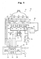
- Fig. 1 is a schematic diagram showing the injection controller 50 of the first embodiment.
- the injection controller 50 is provided with a fuel supply system 20 for supplying fuel to the internal combustion engine 10, a control system 30 for controlling fuel injection with the fuel supply system 20, and a detection system 40 having various types of sensors for providing the control system 30 with detection signals (some of the control data).
- the internal combustion engine 10 has four cylinders #1 through #4.
- Each of the cylinders #1 through #4 includes a combustion chamber 11 connected to an intake passage 12.
- the intake passage 12 includes four intake ports 12a, each of which is connected to a corresponding one of the combustion chambers 11, and a surge tank 12b connected to the intake ports 12a.
- the fuel supply system 20 is provided with four direct injection valves 21, arranged in correspondence with the cylinders #1 through #4 to directly inject fuel into the combustion chambers 11 of the cylinders #1 through #4, and four intake passage injection valves 22 arranged in correspondence with the cylinders #1 through #4 to inject fuel into the intake passage 12.
- the intake passage injection valve 22 in the first embodiment is a port injection valve for injecting fuel into the corresponding intake port 12a.
- the intake passage injection valve 22 may inject fuel into the surge tank 12b (generally referred to as cold start injector).
- the intake passage injection valve 22 is referred to as the "port injection valve 22.”
- Fuel stored in a fuel tank 23 is allocated to the direct injection valves 21 and the port injection valves 22. That is, the fuel in the fuel tank 23 is supplied to the port injection valves 22 by a feed pump 24. Some of the fuel pumped by the feed pump 24 is also supplied to the direct injection valves 21 through a delivery pipe 26 after being pressurized to a high pressure by a supply pump 25.
- the direct injection valves 21 and the port injection valves 22 are each provided with an electromagnetic solenoid (not shown), which is connected to the control system 30.
- the control system 30 provides drive signals to each solenoid for setting the amount of fuel injection and time of fuel injection of the associated injection valve 21 and 22.
- the internal combustion engine 10 is provided with a spark plug 13 for each of the cylinders #1 through #4.
- the spark plug 13 is connected to an igniter 14, provided with a built-in ignition coil (not shown), which is connected to the control system 30.
- the control system 30 provides an ignition signal to the igniter 14 to set the ignition timing of the ignition coil.
- a throttle valve 15 for regulating the amount of intake air drawn into each combustion chamber 11 through the intake passage 12 is provided in the intake passage 12 upstream of the surge tank 12b.
- a throttle motor 16, which is mounted on the throttle valve 15, is controlled by the control system 30. The opening of the throttle valve 15 is regulated by the throttle motor 16.
- the control system 30 which is provided with an electronic control unit (hereinafter referred to as an "ECU") 31 for performing each type of operation control in the internal combustion engine 10, controls the electromagnetic solenoids of the direct injection valves 21 and the port injection valves 22, the igniters 14, and the throttle motor 16 with the ECU 31.
- ECU electronice control unit
- the ECU 31 includes a calculation section 32 for executing arithmetic processes, a storage section 33 for storing various kinds of control programs and data referred to when executing the programs, an output section 34 for outputting drive signals to the injection valves 21 and 22 (electromagnetic solenoids) and the like, and an input section 35 for inputting detection signals from the various types of sensors.
- a starter 17 for driving a crankshaft (not shown) of the internal combustion engine 10 during an engine starting operation until the internal combustion engine 10 is capable of spontaneous operation.
- the starter 17 begins the starting operation (cranking) when an ignition switch 19 connected to the ECU 31 is turned to the starting position.
- the detection system 40 is provided with an acceleration sensor 41, a coolant temperature sensor 42, throttle sensor 43, a speed sensor 44, and a cylinder discrimination sensor 45.
- the acceleration sensor 41 is provided near the accelerator pedal 18, and detects the amount of depression (accelerator opening) of the accelerator pedal.
- the coolant temperature sensor 42 which is located in a water jacket (not shown) of the internal combustion engine 10, detects the temperature of the engine coolant (engine coolant temperature).
- the throttle sensor 43 detects the opening of the throttle valve 15 (throttle opening). The detection signals of these sensors 41 through 43 are provided to the calculation section 32 after the signals are subjected to proper A/D (analog/digital) conversion in the input section 35.
- the speed sensor 44 which is located near the crankshaft (not shown), generates a detection signal corresponding to the number of rotations of the crankshaft, and provides the detection signal to the input section 35.
- the cylinder discrimination sensor 45 which is located near a camshaft (not shown), generates detection signals corresponding to the rotation of the camshaft, and provides the detection signal to the input section 35.
- the input section 35 adjusts the waveform of the detection signals of the sensors 44 and 45 and generates pulse signals synchronized with the rotation of the crankshaft or camshaft. These pulse signals are sent to the calculation section 32.
- the calculation section 32 calculates the rotation speed (engine speed) and rotation phase angle (crank angle) of the crankshaft based on these pulse signals.
- the ECU 31 detects the operating condition of the internal combustion engine 10 based on the detection signals from the acceleration sensor 41 and the speed sensor 44.
- the ECU 31 switches the fuel injection mode of the injection valves 21 and 22 in accordance with the engine operation conditions by driving at least either one of the direct injection valves 21 and the port injection valves 22. More specifically, the ECU 31 executes a first fuel injection mode with the direct injection valves 21 and a second fuel injection mode with the port injection valve 22. Furthermore, the ECU 31 is capable of injecting fuel using both the direct injection valves 21 and the port injection valves 22.
- fuel is only injected from the port injection valves 22 in the low coolant temperature range (cool time), in which it is difficult to vaporize the fuel mist, or in the low speed range (particularly the idling range), in which the piston speed is low.
- the direct injection valves 21 inject fuel while the engine is operating in the low coolant temperature range or the low speed range, the fuel mist configuration is adversely affected, such that combustion is more sluggish and the combustion state deteriorates more compared to when fuel is injected by the port injection valve 22.
- the direct injection valve 21 Since the direct injection valve 21 is exposed to the high temperature combustion gas in the combustion chamber 11, deposits readily adhere to the nozzle hole 21a of each injection valve 21. The accumulation of deposits at the nozzle hole occurs more markedly particularly when fuel is injected only by the port injection valve 22. These deposits block fuel injection from the nozzle hole and reduce the amount of fuel injected by the direct injection valve 21. When the amount of fuel injected by the direct injection valve 21 is less than a proper value (required value), misfire and unsatisfactory combustion may occur.
- the ECU 31 forcibly switches the fuel injection mode such that only the direct injection valve 21 injects fuel for a predetermined period based on predetermined conditions during the operating period in which fuel is injected by the port injection valve 22. Accordingly, accumulation of deposits on the nozzle hole 21a is suppressed, and accumulated deposits are eliminated.
- the forcible switching of the fuel injection mode specifically refers to switching the injection valve that is used to the direct injection valves 21.
- the ECU 31 executes a control routine corresponding to the first processing mode to switch the fuel injection mode.
- This control routine is stored in the storage section 33 of the ECU 31.
- Fig. 2 is a flowchart showing the control routine of the first processing mode.
- the first processing mode is designed for deposit prevention. In this mode, after the ignition switch 19 is turned ON, that is, after the engine starts, deposit prevention is accomplished by forcibly switching the injection valve for a predetermined period from the port injection valves 22 to the direct injection valves 21.
- This control routine is executed by the ECU 31 as, for example, an angle interrupt process at a predetermined crank angle.
- the ECU 31 clears the mode control flag exinjdp (exinjdp ⁇ "0") as an initialization process in the control of the first processing mode.
- the ECU 31 first determines whether or not the mode control flag exinjdp is set at "0" (step S110). When the flag exinjdp is determined to be set at "1" at this time, the ECU 31 ends this process.
- step S110: YES the ECU 31 detects the fuel injection amount QINJST (actual fuel injection amount) of the direct injection valves 21 at this time, and determines whether or not the fuel injection amount QINJST has reached a target value (target injection amount), that is, whether or not the injection amount QINJST is low (step S120).
- target injection amount target injection amount
- the ECU 31 detects the injection amount QINJST by, for example, detecting the change in the air-fuel ratio (A/F) learned value of the air-fuel mixture within the combustion chamber 11 (specifically, the corrected value of the fuel injection amount in the feedback control).
- step S120 YES
- the ECU 31 ends this process after setting the mode control flag exinjdp (exinjdp ⁇ "1") (step S130).
- step S120: NO When it is determined that the fuel injection amount QINJST has not reached the target value (step S120: NO), that is, when it is determined that deposits have reduced the injection amount QINJST, the ECU 31 forcibly switches the injection valves from the port injection valves 22 to the direct injection valves 21. Then, fuel is injected from the direct injection valves 21 for a predetermined period (step S140).
- the ECU 31 switches the fuel injection mode such that the direct injection valves 21 corresponding to the cylinders #1 to #4 inject fuel for a predetermined cycle (for example, one cycle).
- a predetermined cycle for example, one cycle.
- deposits which accumulate at the nozzle hole 21a that is, adhesion material such as carbon and the like which cause deposits (non-solids of deposits) may be blasted away by the force of the injection.
- the fuel injection amount QINJST of the direct injection valve 21 is restored to the target value.
- the ECU 31 temporarily ends the process after the direct injection valves 21 perform fuel injection.
- the ECU 31 determines whether or not the mode control flag exinjdp is set at "0" in step S110. When it is determined that the flag is set at "0" in step S110, the ECU 31 determines whether or not the fuel injection amount QINJST matches the target value in step S120. When the ECU 31 determines that the fuel injection amount QINJST does not match the target value, the injection valve is forcibly switched from the port injection valves 22 to the direct injection valves 21, which perform fuel injection for a predetermined period, in the same manner as described above.
- the ECU 31 forcibly switches the injection valves to the direct injection valves 21. Accordingly, deposits that have accumulated at the nozzle hole 21a are blasted away and removed by the force of the injection. Furthermore, when the direct injection valve 21 performs fuel injection, the heat of fuel vaporization is expelled from the nozzle hole 21a, and the nozzle hole 21a is cooled. As a result, fresh accumulation of deposits at the nozzle hole 21a is prevented.
- the temperature of the nozzle hole 21a of the direct injection valve 21 and the temperature of the fuel injected from the direct injection valve 21 is lower than during normal engine operation. It has been confirmed through experiments that the deposit blasting effect is increased when the temperature of the nozzle hole 21a and fuel temperature are low (when the engine is cold). Accordingly, it is preferred that deposit prevention be performed when starting the engine during which the temperature of the nozzle hole 21a and the fuel temperature are low.
- the injection controller 50 of the first embodiment has the advantages described below.
- the first embodiment may be variously modified as described below.
- the ECU 31 detects the fuel injection amount QINJST of the direct injection valve 21 by detecting the change in an air-fuel ratio learned value.
- the ECU 31 performs the switching control to the direct injection valves 21 until the fuel injection amount QINJST recovers to the target value.
- the switching control also may be performed under the conditions described below.
- the deposit blasting effect is high when the temperature of the nozzle hole 21a and the fuel temperature are low as described above.
- the ECU 31 also may perform switching control when these temperatures are less than predetermined temperatures based on detection signals from sensors detecting the fuel temperature and the temperature of the nozzle hole 21a. In this case, deposit prevention is achieved during the time in which the blasting effect is high.
- sensors for directly detecting the nozzle hole temperature and fuel temperature may be used.
- the nozzle hole temperature and the fuel temperature may be estimated based on the coolant temperature detection result using the coolant temperature sensor 42.
- a fuel injection controller 50 of an internal combustion engine 10 according to a second embodiment of the present invention will now be described with reference to Figs. 3 and 4 focusing on parts differing from the first embodiment.
- the ECU 31 executes a control routine corresponding to a second processing mode in addition to the control routine corresponding to the first processing mode of the first embodiment in order to switch the fuel injection mode.
- These control routines are stored in the storage section 33 of the ECU 31.
- Fig. 3 is a flowchart showing the control routine of the second processing mode.
- the second processing mode is designed for deposit prevention by forcibly switching the injection valve from the port injection valve 22 to the direct injection valve 21 until the engine stops after the ignition switch 19 is turned OFF based on the mode control flag exinjdp of the first processing mode.
- This control routine is executed through the ECU 31 as, for example, an angle interrupt process at a predetermined crank angle when the ignition switch 19 is turned OFF.
- the ECU 31 first determines whether or not the mode control flag exinjdp is set at "1" (step S210). When it is determined that the mode control flag exinjdp is set at "1" (step S210: YES), the ECU 31 ends this process. That is, the ECU 31 has performed the deposit elimination process through the first processing mode when the mode control flag exirijdp is set at "1". In other words, the determination is that the fuel injection amount QINJST (actual fuel injection amount) has recovered to the target value (target injection amount). Then, the ECU 31 ends this process since deposit prevention through the second processing mode is unnecessary.
- step S210 NO
- the ECU 31 forcibly switches the injection valves from the port injection valves 22 to the direct injection valves 21, and the direct injection valves 21 performs fuel injection for a predetermined period (step S220). That is, when the mode control flag exinjdp is set at "0", the ECU 31 determines that there is a possibility that deposits have accumulated and thus performs fuel injection with the direct injection valves 21.
- the ECU 31 switches the fuel injection mode so that fuel is injected by the direct injection valves 21 corresponding to the cylinders #1 through #4 for one cycle.
- deposits which accumulate at the nozzle hole 21a that is, adhesion material such as carbon and the like which cause deposits (non-solids of deposits) can be blasted away by the force of the injection.
- the fuel injection amount QINJST of the direct injection valve 21 is restored to the target value.
- the ECU 31 sets the mode control flag exinjdp to "1", and ends the process (step S230).
- the ECU 31 forcibly switches the injection valves to the direct injection valves 21. Accordingly, the deposits accumulated at each nozzle hole 21a of the direct injection valve 21 are removed. Furthermore, when the direct injection valve 21 performs fuel injection, the heat of fuel vaporization is expelled from the nozzle hole 21a, and the nozzle hole 21a is cooled. As a result, the accumulation of new deposits at the nozzle hole 21a is prevented.
- Fig. 4 is a graph showing the relationship between the engine operation time and injection amount reduction rate of the direct injection valves 21 when executing controls to switch the fuel injection modes in the first processing mode and the second processing mode.
- the injection amount reduction rate of the direct injection valve 21 gradually rises as the engine operation time becomes longer.
- the ECU 31 executes the second processing mode.
- the ECU 31 restores the injection amount reduction rate by forcibly switching the injection valves to the direct injection valves 21 until the engine stops.
- the first processing mode is executed, and the injection valve is forcibly switched to the direct injection valve 21.
- deposits accumulated at the nozzle hole 21a of the direct injection valve 21 are removed, thereby restoring the injection amount reduction rate.
- the injection controller 50 of the second embodiment has the advantages described below.
- the second embodiment may be modified as described below.
- the process of the second processing mode is linked to the mode control flag exinjdp of the first processing mode.
- the ECU 31 also may execute the switching control of the second processing mode regardless of the value of the flag exinjdp. Deposit prevention is performed when the engine is stopped and adverse combustion is negligible.
- a fuel injection controller 50 of an internal combustion engine 10 according to a third embodiment of the present invention will now be described with reference to Fig. 5 focusing on parts differing from the first and second embodiments.
- the ECU 31 executes a control routine corresponding to a third processing mode to switch the fuel injection mode.
- This control routine is stored in the storage section 33 of the ECU 31.
- Fig. 5 is a flowchart showing the control routine of the third processing mode.
- the ECU 31 estimates the amount of deposits accumulated on the nozzle hole 21a of each direct injection valve 21 when the engine is operating with fuel continuously injected from the port injection valves 22.
- the ECU 31 performs deposit prevention by forcibly switching the injection valves from the port injection valves 22 to the direct injection valves 21 for a predetermined interval based on this estimation.
- This control routine is executed by the ECU 31 as an angle interrupt process, for example, at predetermined crank angles.
- the ECU 31 estimates the deposit accumulation amount based on operation condition parameters (engine operating state) of the internal combustion engine 10 that is correlated with the deposit accumulation amount.
- the ECU 31 obtains the operation condition parameter of the internal combustion engine 10 and estimates the amount of adhered deposits per unit time collected on the nozzle hole 21a based on this calculated operation condition parameter. The ECU 31 then adds the estimated deposit adhesion amount with a counter (not shown) and records the sum as the deposit accumulation amount.
- the operation condition parameter used for the estimation of the deposit accumulation amount is a quantity correlating to the temperature of the nozzle hole 21a and the engine operating combustion conditions.
- parameters usable as the operation condition parameter include engine speed detected by the speed sensor 44, engine load detected by the acceleration sensor 41 or speed sensor 44, coolant temperature detected by the coolant temperature sensor 42, and the like.
- the ECU 31 performs the switching control to the direct injection valve 21 based on the estimation value of the deposit accumulation amount.
- the ECU 31 determines whether or not the deposit accumulation amount estimated as described above, that is, the count value ecinjdp of the counter, exceeds a predetermined threshold value pl (step S310).
- step S310 When it is determined that the count value ecinjdp exceeds the threshold value pl, that is, the condition ecinjdp > pl is satisfied (step S310: YES), the ECU 31 forcibly switches the injection valves from the port injection valves 22 to the direct injection valves 21 to perform fuel injection with the direct injection valves 21 (step S320).
- the ECU 31 switches the fuel injection mode such that the direct injection valves 21 corresponding to the cylinders #1 through #4 inject fuel for a predetermined cycle (for example, one cycle).
- a predetermined cycle for example, one cycle.
- the deposits accumulated on each nozzle hole 21a and adhesion material, such as carbon and the like which cause deposits (non-solids such as deposits), are blasted away by the force of the injection by starting fuel injection with the direct injection valves 21 as described above. In this way, the fuel injection amount QINJST of the direct injection valve 21 recovers to the target value.
- the ECU 31 detects the fuel injection amount QINJST of the injection valve 21 to determine whether or not the injection amount QINJST has recovered to the target value (step S330).
- the ECU 31 detects the injection amount QINJST by detecting, for example, the change in the air-fuel ratio learned value of the air-fuel mixture formed in the combustion chamber 11.
- step S310 NO
- the ECU 31 again obtains the count value ecinjdp of the counter based on the operation condition parameters of the internal combustion engine 10. Specifically, the adhesion amount of accumulated deposit on the nozzle hole 21a is estimated based on the operation condition parameter to determine an additional value eicinjdp (step S350). Then, the ECU 31 calculates a new count value ecinjdp by adding the additional value eicinjdp to the present count value ecinjdp (step S360). Thereafter, the ECU 31 temporarily ends this process.
- the ECU 31 determines whether or not the count value ecinjdp calculated in step S360 exceeds the threshold value pl in step S310.
- the injection valve is forcibly switched to the direct injection valves 21 to perform fuel injection with the direct injection valves 21 as described above.
- the injection valves are forcibly switched from the port injection valves 22 to the direct injection valves 21. Accordingly, deposits accumulating on the nozzle hole 21a of each direct injection valve 21 are blasted away by the force of the injection. Furthermore, the heat of fuel vaporization is expelled from the nozzle hole 21a, and the nozzle hole 21a is cooled when the direct injection valve 21 performs fuel injection. As a result, accumulation of new deposits at the nozzle hole 21a is prevented.
- the injection controller 50 of the third embodiment has the advantages described below.
- the ECU 31 controls the fuel injection of the direct injection valves 21 corresponding to the cylinders #1 through #4 for one cycle.
- the direct injection valves 21 corresponding to the cylinders #1 through #4 also may perform fuel injection for two cycles.
- the fuel injection may be performed for more than two cycles insofar as adverse combustion does not occur.
- Fuel injection by the direct injection valves 21 may be performed over a fixed period.
- the injection controller of the present invention requires only at least one of the control routines corresponding to the first through third processing modes.
Description
- The present invention relates to an injection controller for an internal combustion engine, and more specifically, relates to an injection controller for an internal combustion engine provided with a direct fuel injection valve, which injects fuel directly into the cylinder, and an intake passage fuel injection valve, which injects fuel into an intake passage.
- Conventionally, certain internal combustion engines are provided with a direct injection valve (in-cylinder injection valve) for injecting fuel directly into the cylinder in addition to a port injection valve for injecting fuel into an intake port of an intake passage (for example, refer to
Japanese Laid-Open Patent Publication No. 2002-364409 - The direct injection valve includes a nozzle hole for injecting fuel. Since the direct injection valve is exposed to high-temperature combustion gas in the combustion chamber, deposits tend to adhere to the nozzle hole of the direct injection valve. When the direct injection valve is injecting fuel, the nozzle hole is cooled by vaporized fuel. However, when the direct injection valve is not injecting fuel, the nozzle hole is not cooled by vaporized fuel and the temperature of the nozzle hole increases such that deposits accumulate on the nozzle hole. Such deposits obstruct the injection of fuel from the nozzle hole of the direct injection valve. As a result, the shape of fuel mist may change (particle diameter increases) or the amount of injected fuel may decreases so as to be less than the amount required. There is concern in this case that misfire and unsatisfactory combustion may occur.
- In the apparatus described in
Japanese Laid-Open Patent Publication No. 2002-364409 - In the method for allocating some of the injected fuel of the port injection valve to the direct injection valve described above, when the required amount of injected fuel is relatively low, the portion of the injected fuel allocated to the direct injection valve is also relatively small. Therefore, an adequate cooling effect is not obtained, and the accumulation of deposits is not sufficiently prevented.
- When a small amount of injected fuel is required and the fuel allocated to the direct injection valve falls below the appropriate minimum amount (minimum value ensuring linearity of the injected amount relative to valve open time of the injection valve), the direct injection valve cannot inject fuel normally. In this case, there is concern that misfire and unsatisfactory combustion may occur.
- A fuel injection system for GDI internal combustion engines and a method for operating this fuel injection system are further known from
US 2003/051707 A1 . This fuel injection system has a second injection valve in the intake tube. By injecting fuel into the intake tube at intervals by means of the second injection valve, the formation of deposits in the intake tube and on the inlet valve, which are produced due to the recirculation of exhaust gas through the exhaust recirculation tube, can be prevented and possibly existing deposits can be broken down. - Moreover,
document EP 1 249 600 A2 discloses a control for injecting fuel is performed both through a first nozzle hole and a second nozzle hole by setting a needle valve at a high-lift position in a fuel injector. The fuel injection is performed only through the first nozzle hole, not through the second nozzle hole by setting the needle valve at a low-lift position of the fuel injector. When operation of an internal combustion engine continues for a predetermined period of time under conditions requiring the needle valve to be set in the low-lift position, control for injecting the fuel through the nozzle hole is performed. - It is an object of the present invention to provide an injection controller for internal combustion engines which ideally suppresses the accumulation of deposits on the nozzle hole of the direct injection valve.
- One embodiment of the present invention is a controller for controlling the injection of fuel in an internal combustion engine including a cylinder and an intake passage connected to the cylinder. The controller includes a direct injection valve for injecting fuel into the cylinder. An intake passage injection valve injects fuel into the intake passage. A switching means, connected to the direct injection valve and the intake passage injection valve, executes a first fuel injection mode with the direct injection valve and a second fuel injection mode with the intake passage injection valve. The switching means switches injection modes from the second fuel injection mode to the first fuel injection mode for a predetermined period when fuel is to be injected in the second fuel injection mode.
- Another embodiment of the present invention is a method for controlling fuel injection in an internal combustion engine including a cylinder and an intake passage connected to the cylinder. The method includes executing a first fuel injection mode for injecting fuel into a cylinder with a direct injection valve, executing a second fuel injection mode for injecting fuel into the intake passage with an intake passage injection valve, and switching fuel injection modes from the second fuel injection mode to the first fuel injection mode for a predetermined period when fuel is to be injected in the second fuel injection mode.
- Other embodiments and advantages of the present invention will become apparent from the following description, taken in conjunction with the accompanying drawings, illustrating by way of example the principles of the invention.
- The invention, and preferred objects and advantages thereof, may best be understood by reference to the following description of the certain exemplifying embodiments together with the accompanying drawings in which:
-
Fig. 1 is a schematic diagram showing an injection controller for an internal combustion engine according to a first embodiment of the present invention; -
Fig. 2 is a flowchart showing a control routine in a first processing mode of the first embodiment; -
Fig. 3 is a flowchart showing a control routine in a second processing mode of a second embodiment; -
Fig. 4 is a graph showing the relationship between the engine operation time and the injection amount decrease rate of the direct injection valve; and -
Fig. 5 is a flowchart showing the control routine in a third processing mode of a third embodiment. - An
injection controller 50 for aninternal combustion engine 10 according to a first embodiment of the present invention will now be described with reference toFigs. 1 and2 . -
Fig. 1 is a schematic diagram showing theinjection controller 50 of the first embodiment. - The
injection controller 50 is provided with afuel supply system 20 for supplying fuel to theinternal combustion engine 10, acontrol system 30 for controlling fuel injection with thefuel supply system 20, and adetection system 40 having various types of sensors for providing thecontrol system 30 with detection signals (some of the control data). - In the first embodiment, the
internal combustion engine 10 has fourcylinders # 1 through #4. Each of thecylinders # 1 through #4 includes acombustion chamber 11 connected to anintake passage 12. Specifically, theintake passage 12 includes fourintake ports 12a, each of which is connected to a corresponding one of thecombustion chambers 11, and asurge tank 12b connected to theintake ports 12a. - The
fuel supply system 20 is provided with fourdirect injection valves 21, arranged in correspondence with thecylinders # 1 through #4 to directly inject fuel into thecombustion chambers 11 of thecylinders # 1 through #4, and four intakepassage injection valves 22 arranged in correspondence with thecylinders # 1 through #4 to inject fuel into theintake passage 12. The intakepassage injection valve 22 in the first embodiment is a port injection valve for injecting fuel into thecorresponding intake port 12a. Alternatively, the intakepassage injection valve 22 may inject fuel into thesurge tank 12b (generally referred to as cold start injector). Hereinafter, the intakepassage injection valve 22 is referred to as the "port injection valve 22." - Fuel stored in a
fuel tank 23 is allocated to thedirect injection valves 21 and theport injection valves 22. That is, the fuel in thefuel tank 23 is supplied to theport injection valves 22 by afeed pump 24. Some of the fuel pumped by thefeed pump 24 is also supplied to thedirect injection valves 21 through adelivery pipe 26 after being pressurized to a high pressure by asupply pump 25. - The
direct injection valves 21 and theport injection valves 22 are each provided with an electromagnetic solenoid (not shown), which is connected to thecontrol system 30. Thecontrol system 30 provides drive signals to each solenoid for setting the amount of fuel injection and time of fuel injection of the associatedinjection valve - The
internal combustion engine 10 is provided with aspark plug 13 for each of thecylinders # 1 through #4. Thespark plug 13 is connected to anigniter 14, provided with a built-in ignition coil (not shown), which is connected to thecontrol system 30. Thecontrol system 30 provides an ignition signal to theigniter 14 to set the ignition timing of the ignition coil. - A
throttle valve 15 for regulating the amount of intake air drawn into eachcombustion chamber 11 through theintake passage 12 is provided in theintake passage 12 upstream of thesurge tank 12b. Athrottle motor 16, which is mounted on thethrottle valve 15, is controlled by thecontrol system 30. The opening of thethrottle valve 15 is regulated by thethrottle motor 16. - The
control system 30, which is provided with an electronic control unit (hereinafter referred to as an "ECU") 31 for performing each type of operation control in theinternal combustion engine 10, controls the electromagnetic solenoids of thedirect injection valves 21 and theport injection valves 22, theigniters 14, and thethrottle motor 16 with theECU 31. - The ECU 31 includes a
calculation section 32 for executing arithmetic processes, astorage section 33 for storing various kinds of control programs and data referred to when executing the programs, anoutput section 34 for outputting drive signals to theinjection valves 21 and 22 (electromagnetic solenoids) and the like, and aninput section 35 for inputting detection signals from the various types of sensors. - Connected to the
output section 34 is astarter 17 for driving a crankshaft (not shown) of theinternal combustion engine 10 during an engine starting operation until theinternal combustion engine 10 is capable of spontaneous operation. Thestarter 17 begins the starting operation (cranking) when anignition switch 19 connected to theECU 31 is turned to the starting position. - The
detection system 40 is provided with anacceleration sensor 41, acoolant temperature sensor 42,throttle sensor 43, aspeed sensor 44, and acylinder discrimination sensor 45. - The
acceleration sensor 41 is provided near theaccelerator pedal 18, and detects the amount of depression (accelerator opening) of the accelerator pedal. Thecoolant temperature sensor 42, which is located in a water jacket (not shown) of theinternal combustion engine 10, detects the temperature of the engine coolant (engine coolant temperature). Thethrottle sensor 43 detects the opening of the throttle valve 15 (throttle opening). The detection signals of thesesensors 41 through 43 are provided to thecalculation section 32 after the signals are subjected to proper A/D (analog/digital) conversion in theinput section 35. - The
speed sensor 44, which is located near the crankshaft (not shown), generates a detection signal corresponding to the number of rotations of the crankshaft, and provides the detection signal to theinput section 35. Thecylinder discrimination sensor 45, which is located near a camshaft (not shown), generates detection signals corresponding to the rotation of the camshaft, and provides the detection signal to theinput section 35. Theinput section 35 adjusts the waveform of the detection signals of thesensors calculation section 32. Thecalculation section 32 calculates the rotation speed (engine speed) and rotation phase angle (crank angle) of the crankshaft based on these pulse signals. - The
ECU 31 detects the operating condition of theinternal combustion engine 10 based on the detection signals from theacceleration sensor 41 and thespeed sensor 44. TheECU 31 switches the fuel injection mode of theinjection valves direct injection valves 21 and theport injection valves 22. More specifically, theECU 31 executes a first fuel injection mode with thedirect injection valves 21 and a second fuel injection mode with theport injection valve 22. Furthermore, theECU 31 is capable of injecting fuel using both thedirect injection valves 21 and theport injection valves 22. - In the
injection controller 50, fuel is only injected from theport injection valves 22 in the low coolant temperature range (cool time), in which it is difficult to vaporize the fuel mist, or in the low speed range (particularly the idling range), in which the piston speed is low. This is because when thedirect injection valves 21 inject fuel while the engine is operating in the low coolant temperature range or the low speed range, the fuel mist configuration is adversely affected, such that combustion is more sluggish and the combustion state deteriorates more compared to when fuel is injected by theport injection valve 22. - Since the
direct injection valve 21 is exposed to the high temperature combustion gas in thecombustion chamber 11, deposits readily adhere to thenozzle hole 21a of eachinjection valve 21. The accumulation of deposits at the nozzle hole occurs more markedly particularly when fuel is injected only by theport injection valve 22. These deposits block fuel injection from the nozzle hole and reduce the amount of fuel injected by thedirect injection valve 21. When the amount of fuel injected by thedirect injection valve 21 is less than a proper value (required value), misfire and unsatisfactory combustion may occur. - The
ECU 31 forcibly switches the fuel injection mode such that only thedirect injection valve 21 injects fuel for a predetermined period based on predetermined conditions during the operating period in which fuel is injected by theport injection valve 22. Accordingly, accumulation of deposits on thenozzle hole 21a is suppressed, and accumulated deposits are eliminated. In the first embodiment, the forcible switching of the fuel injection mode specifically refers to switching the injection valve that is used to thedirect injection valves 21. - Details of the switching control for switching the fuel injection mode for deposit prevention is described below with reference to
Fig. 2 . - In the first embodiment, the
ECU 31 executes a control routine corresponding to the first processing mode to switch the fuel injection mode. This control routine is stored in thestorage section 33 of theECU 31. -
Fig. 2 is a flowchart showing the control routine of the first processing mode. The first processing mode is designed for deposit prevention. In this mode, after theignition switch 19 is turned ON, that is, after the engine starts, deposit prevention is accomplished by forcibly switching the injection valve for a predetermined period from theport injection valves 22 to thedirect injection valves 21. This control routine is executed by theECU 31 as, for example, an angle interrupt process at a predetermined crank angle. Although not shown in the drawing, when theignition switch 19 is turned ON, theECU 31 clears the mode control flag exinjdp (exinjdp→"0") as an initialization process in the control of the first processing mode. - When the process proceeds to this routine as an interrupt process, the
ECU 31 first determines whether or not the mode control flag exinjdp is set at "0" (step S110). When the flag exinjdp is determined to be set at "1" at this time, theECU 31 ends this process. - When the flag exinjdp is determined to be set at "0" (step S110: YES), the
ECU 31 detects the fuel injection amount QINJST (actual fuel injection amount) of thedirect injection valves 21 at this time, and determines whether or not the fuel injection amount QINJST has reached a target value (target injection amount), that is, whether or not the injection amount QINJST is low (step S120). - In the determination process, the
ECU 31 detects the injection amount QINJST by, for example, detecting the change in the air-fuel ratio (A/F) learned value of the air-fuel mixture within the combustion chamber 11 (specifically, the corrected value of the fuel injection amount in the feedback control). - When the fuel injection amount QINJST is determined to be equal to the target value (step S120: YES), that is, when the injection amount QINJST is determined not to be low, the
ECU 31 ends this process after setting the mode control flag exinjdp (exinjdp → "1") (step S130). - When it is determined that the fuel injection amount QINJST has not reached the target value (step S120: NO), that is, when it is determined that deposits have reduced the injection amount QINJST, the
ECU 31 forcibly switches the injection valves from theport injection valves 22 to thedirect injection valves 21. Then, fuel is injected from thedirect injection valves 21 for a predetermined period (step S140). - Specifically, the
ECU 31 switches the fuel injection mode such that thedirect injection valves 21 corresponding to thecylinders # 1 to #4 inject fuel for a predetermined cycle (for example, one cycle). In this way, deposits which accumulate at thenozzle hole 21a, that is, adhesion material such as carbon and the like which cause deposits (non-solids of deposits) may be blasted away by the force of the injection. As a result, the fuel injection amount QINJST of thedirect injection valve 21 is restored to the target value. TheECU 31 temporarily ends the process after thedirect injection valves 21 perform fuel injection. - Thereafter, when the process proceeds again to this routine (first processing mode) as an interrupt process, the
ECU 31 determines whether or not the mode control flag exinjdp is set at "0" in step S110. When it is determined that the flag is set at "0" in step S110, theECU 31 determines whether or not the fuel injection amount QINJST matches the target value in step S120. When theECU 31 determines that the fuel injection amount QINJST does not match the target value, the injection valve is forcibly switched from theport injection valves 22 to thedirect injection valves 21, which perform fuel injection for a predetermined period, in the same manner as described above. - In the first processing mode, when deposits accumulate at the
nozzle hole 21a of eachdirect injection valve 21, theECU 31 forcibly switches the injection valves to thedirect injection valves 21. Accordingly, deposits that have accumulated at thenozzle hole 21a are blasted away and removed by the force of the injection. Furthermore, when thedirect injection valve 21 performs fuel injection, the heat of fuel vaporization is expelled from thenozzle hole 21a, and thenozzle hole 21a is cooled. As a result, fresh accumulation of deposits at thenozzle hole 21a is prevented. - When the engine starts immediately after the
ignition switch 19 is turned ON, the temperature of thenozzle hole 21a of thedirect injection valve 21 and the temperature of the fuel injected from thedirect injection valve 21 is lower than during normal engine operation. It has been confirmed through experiments that the deposit blasting effect is increased when the temperature of thenozzle hole 21a and fuel temperature are low (when the engine is cold). Accordingly, it is preferred that deposit prevention be performed when starting the engine during which the temperature of thenozzle hole 21a and the fuel temperature are low. - The
injection controller 50 of the first embodiment has the advantages described below. - (1) The
ECU 31 detects the fuel injection amount QINJST (actual fuel injection amount) of thedirect injection valves 21. When the injection amount QINJST is less than the target value (target injection amount), theECU 31 forcibly switches from theport injection valves 22 to thedirect injection valves 21. Thus, thedirect injection valve 21 injects fuel into thecylinders # 1 through #4 for a predetermined cycle (one cycle in the present example). Accordingly, the deposits accumulated at thenozzle hole 21a of thedirect injection valve 21 are blasted away by the force of the injection, and the injection amount QINJST is restored to the target value. - (2) The
nozzle hole 21a is cooled when the associateddirect injection valve 21 injects fuel. This suppresses accumulation of new deposits. - (3) When the fuel injection amount QINJST of the
direct injection valve 21 is low, theECU 31 forcibly switches to thedirect injection valve 21 for a predetermined number of cycles until the injection amount QINJST recovers to the target value. The fuel injection by eachdirect injection valve 21 tends to cause insufficient homogenization of the air-fuel mixture. However, since the switching control is limited to the time until the injection amount recovers to the target value in the first embodiment, the adverse combustion caused by the fuel injected by thedirect injection valve 21 is very slight. - (4) Since the
ECU 31 switches to thedirect injection valves 21 when the engine is started, the deposit blasted away by the fuel injection is very effective. That is, suitable deposit prevention is achieved. - The first embodiment may be variously modified as described below.
- In the first embodiment, the
ECU 31 detects the fuel injection amount QINJST of thedirect injection valve 21 by detecting the change in an air-fuel ratio learned value. When the fuel injection amount is low, theECU 31 performs the switching control to thedirect injection valves 21 until the fuel injection amount QINJST recovers to the target value. Alternatively, the switching control also may be performed under the conditions described below. The deposit blasting effect is high when the temperature of thenozzle hole 21a and the fuel temperature are low as described above. Accordingly, theECU 31 also may perform switching control when these temperatures are less than predetermined temperatures based on detection signals from sensors detecting the fuel temperature and the temperature of thenozzle hole 21a. In this case, deposit prevention is achieved during the time in which the blasting effect is high. In this case, sensors for directly detecting the nozzle hole temperature and fuel temperature may be used. Alternatively, the nozzle hole temperature and the fuel temperature may be estimated based on the coolant temperature detection result using thecoolant temperature sensor 42. - A
fuel injection controller 50 of aninternal combustion engine 10 according to a second embodiment of the present invention will now be described with reference toFigs. 3 and4 focusing on parts differing from the first embodiment. - In the second embodiment, the
ECU 31 executes a control routine corresponding to a second processing mode in addition to the control routine corresponding to the first processing mode of the first embodiment in order to switch the fuel injection mode. These control routines are stored in thestorage section 33 of theECU 31. -
Fig. 3 is a flowchart showing the control routine of the second processing mode. The second processing mode is designed for deposit prevention by forcibly switching the injection valve from theport injection valve 22 to thedirect injection valve 21 until the engine stops after theignition switch 19 is turned OFF based on the mode control flag exinjdp of the first processing mode. This control routine is executed through theECU 31 as, for example, an angle interrupt process at a predetermined crank angle when theignition switch 19 is turned OFF. - When the
ignition switch 19 is turned OFF, the processing proceeds to the routine shown inFig. 3 as an interrupt process. TheECU 31 first determines whether or not the mode control flag exinjdp is set at "1" (step S210). When it is determined that the mode control flag exinjdp is set at "1" (step S210: YES), theECU 31 ends this process. That is, theECU 31 has performed the deposit elimination process through the first processing mode when the mode control flag exirijdp is set at "1". In other words, the determination is that the fuel injection amount QINJST (actual fuel injection amount) has recovered to the target value (target injection amount). Then, theECU 31 ends this process since deposit prevention through the second processing mode is unnecessary. - When it is determined that the mode control flag exinjdp is set at "0" (step S210: NO), the
ECU 31 forcibly switches the injection valves from theport injection valves 22 to thedirect injection valves 21, and thedirect injection valves 21 performs fuel injection for a predetermined period (step S220). That is, when the mode control flag exinjdp is set at "0", theECU 31 determines that there is a possibility that deposits have accumulated and thus performs fuel injection with thedirect injection valves 21. - Specifically, the
ECU 31 switches the fuel injection mode so that fuel is injected by thedirect injection valves 21 corresponding to thecylinders # 1 through #4 for one cycle. In this way, deposits which accumulate at thenozzle hole 21a, that is, adhesion material such as carbon and the like which cause deposits (non-solids of deposits) can be blasted away by the force of the injection. As a result, the fuel injection amount QINJST of thedirect injection valve 21 is restored to the target value. After thedirect injection valve 21 performs fuel injection in this way, theECU 31 sets the mode control flag exinjdp to "1", and ends the process (step S230). - In the second processing mode, when the engine has stopped after the
ignition switch 19 is turned OFF, theECU 31 forcibly switches the injection valves to thedirect injection valves 21. Accordingly, the deposits accumulated at eachnozzle hole 21a of thedirect injection valve 21 are removed. Furthermore, when thedirect injection valve 21 performs fuel injection, the heat of fuel vaporization is expelled from thenozzle hole 21a, and thenozzle hole 21a is cooled. As a result, the accumulation of new deposits at thenozzle hole 21a is prevented. - When the engine is stopped, the effects of adverse combustion during use of the
direct injection valves 21 are negligible. Therefore, it is preferred that such deposit prevention be performed when the engine is stopped. -
Fig. 4 is a graph showing the relationship between the engine operation time and injection amount reduction rate of thedirect injection valves 21 when executing controls to switch the fuel injection modes in the first processing mode and the second processing mode. - As shown in
Fig. 4 , the injection amount reduction rate of thedirect injection valve 21 gradually rises as the engine operation time becomes longer. After the ignition switch is turned OFF at time t1, theECU 31 executes the second processing mode. TheECU 31 restores the injection amount reduction rate by forcibly switching the injection valves to thedirect injection valves 21 until the engine stops. - After the engine is started at time t2 (
ignition switch 19 turned ON), the first processing mode is executed, and the injection valve is forcibly switched to thedirect injection valve 21. As a result, deposits accumulated at thenozzle hole 21a of thedirect injection valve 21 are removed, thereby restoring the injection amount reduction rate. - In addition to the advantages of the first embodiment, the
injection controller 50 of the second embodiment has the advantages described below. - (1) After the
ignition switch 19 is turned OFF, theECU 31 forcibly switches the injection valves from theport injection valves 22 to thedirect injection valves 21. Thedirect injection valves 21 corresponding to thecylinders # 1 through #4 inject fuel for one cycle, and then the engine stops. Deposits accumulated at thenozzle hole 21a of thedirect injection valve 21 are blasted away by the force of the injection, and the injection amount QINJST of thedirect injection valve 21 is restored to the target value. - (2) Each
nozzle hole 21a is cooled when the correspondingdirect injection valve 21 performs fuel injection in the same manner as in the first embodiment. Accordingly, the accumulation of new deposits is suppressed when the engine stops. - (3) When the engine is stopped, the effects of adverse combustion when using the
direct injection valve 21 are negligible. Since theECU 31 switches to theinjection valves 21 when the engine is stopped, deposit prevention is performed in an optimal manner. - The second embodiment may be modified as described below.
- In the second embodiment, the process of the second processing mode is linked to the mode control flag exinjdp of the first processing mode. Alternatively, when the
ignition switch 19 is turned OFF, theECU 31 also may execute the switching control of the second processing mode regardless of the value of the flag exinjdp. Deposit prevention is performed when the engine is stopped and adverse combustion is negligible. - A
fuel injection controller 50 of aninternal combustion engine 10 according to a third embodiment of the present invention will now be described with reference toFig. 5 focusing on parts differing from the first and second embodiments. - In the third embodiment, the
ECU 31 executes a control routine corresponding to a third processing mode to switch the fuel injection mode. This control routine is stored in thestorage section 33 of theECU 31. -
Fig. 5 is a flowchart showing the control routine of the third processing mode. In the third processing mode, theECU 31 estimates the amount of deposits accumulated on thenozzle hole 21a of eachdirect injection valve 21 when the engine is operating with fuel continuously injected from theport injection valves 22. TheECU 31 performs deposit prevention by forcibly switching the injection valves from theport injection valves 22 to thedirect injection valves 21 for a predetermined interval based on this estimation. This control routine is executed by theECU 31 as an angle interrupt process, for example, at predetermined crank angles. - In the third embodiment, the
ECU 31 estimates the deposit accumulation amount based on operation condition parameters (engine operating state) of theinternal combustion engine 10 that is correlated with the deposit accumulation amount. - Specifically, the
ECU 31 obtains the operation condition parameter of theinternal combustion engine 10 and estimates the amount of adhered deposits per unit time collected on thenozzle hole 21a based on this calculated operation condition parameter. TheECU 31 then adds the estimated deposit adhesion amount with a counter (not shown) and records the sum as the deposit accumulation amount. - The operation condition parameter used for the estimation of the deposit accumulation amount is a quantity correlating to the temperature of the
nozzle hole 21a and the engine operating combustion conditions. Examples of parameters usable as the operation condition parameter include engine speed detected by thespeed sensor 44, engine load detected by theacceleration sensor 41 orspeed sensor 44, coolant temperature detected by thecoolant temperature sensor 42, and the like. When estimating the deposit accumulation amount, a method using the parameters separately, a method using these parameters in combination, or a method weighting each of the parameters in accordance with the degree of correlation to the deposit accumulation may be employed. - In the control routine of the third processing mode, the
ECU 31 performs the switching control to thedirect injection valve 21 based on the estimation value of the deposit accumulation amount. - Specifically, when the processing proceeds to this routine as an interrupt process, the
ECU 31 determines whether or not the deposit accumulation amount estimated as described above, that is, the count value ecinjdp of the counter, exceeds a predetermined threshold value pl (step S310). - When it is determined that the count value ecinjdp exceeds the threshold value pl, that is, the condition ecinjdp > pl is satisfied (step S310: YES), the
ECU 31 forcibly switches the injection valves from theport injection valves 22 to thedirect injection valves 21 to perform fuel injection with the direct injection valves 21 (step S320). - In the third embodiment, the
ECU 31 switches the fuel injection mode such that thedirect injection valves 21 corresponding to thecylinders # 1 through #4 inject fuel for a predetermined cycle (for example, one cycle). The deposits accumulated on eachnozzle hole 21a and adhesion material, such as carbon and the like which cause deposits (non-solids such as deposits), are blasted away by the force of the injection by starting fuel injection with thedirect injection valves 21 as described above. In this way, the fuel injection amount QINJST of thedirect injection valve 21 recovers to the target value. - After the
direct injection valves 21 performs fuel injection, theECU 31 detects the fuel injection amount QINJST of theinjection valve 21 to determine whether or not the injection amount QINJST has recovered to the target value (step S330). - In the same manner as in the first processing mode, the
ECU 31 detects the injection amount QINJST by detecting, for example, the change in the air-fuel ratio learned value of the air-fuel mixture formed in thecombustion chamber 11. - When it is determined that the fuel injection amount QINJST has recovered to the target value (step S330: YES), the
ECU 31 clears the count value ecinjdp of the counter (ecinjdp="0") and ends this process (step S340). However, when it is determined that the fuel injection amount QINJST has not recovered to the target value (step S330: NO), theECU 31 returns to step S320 so that thedirect injection valves 21 corresponding to thecylinders # 1 through #4 again inject fuel for one cycle. Thereafter, theECU 31 again detects the fuel injection amount QINJST in step S330 to determine whether or not the fuel injection amount QINJST has recovered to the target value. The fuel injection amount QINJST recovers to the target value through the control loop of steps S320 and S330. - When it is determined that the count value ecinjdp has not exceeded the threshold value pl (step S310: NO), the
ECU 31 again obtains the count value ecinjdp of the counter based on the operation condition parameters of theinternal combustion engine 10. Specifically, the adhesion amount of accumulated deposit on thenozzle hole 21a is estimated based on the operation condition parameter to determine an additional value eicinjdp (step S350). Then, theECU 31 calculates a new count value ecinjdp by adding the additional value eicinjdp to the present count value ecinjdp (step S360). Thereafter, theECU 31 temporarily ends this process. - When the process again proceeds to this routine (third processing mode) as an interrupt process, the
ECU 31 determines whether or not the count value ecinjdp calculated in step S360 exceeds the threshold value pl in step S310. When theECU 31 determines that the count value ecinjdp exceeds the threshold value pl, the injection valve is forcibly switched to thedirect injection valves 21 to perform fuel injection with thedirect injection valves 21 as described above. - In the third processing mode, when the fuel injection is continuously performed by the
port injection valves 22, and the estimated value (count value ecinjdp) of the deposit accumulation amount exceeds the threshold value pl, the injection valves are forcibly switched from theport injection valves 22 to thedirect injection valves 21. Accordingly, deposits accumulating on thenozzle hole 21a of eachdirect injection valve 21 are blasted away by the force of the injection. Furthermore, the heat of fuel vaporization is expelled from thenozzle hole 21a, and thenozzle hole 21a is cooled when thedirect injection valve 21 performs fuel injection. As a result, accumulation of new deposits at thenozzle hole 21a is prevented. - In addition to the advantages of the first and second embodiments, the
injection controller 50 of the third embodiment has the advantages described below. - (1) When fuel is continuously injected from the
port injection valves 22, theECU 31 estimates the amount of deposit accumulation on thenozzle hole 21a of thedirect injection valve 21, and records the estimated value as the count value ecinjdp. When the count value ecinjdp exceeds the threshold value pl, theECU 31 forcibly switches the injection valves from theport injection valves 22 to thedirect injection valves 21, and thedirect injection valves 21 corresponding to thecylinders # 1 through #4 perform fuel injection for a predetermined cycle (in the present example, one cycle). Accordingly, deposits accumulating on thenozzle hole 21a of thedirect injection valve 21 are blasted away by the force of the injection, and the reduced injection amount QINJST recovers to its target value. - (2) Each
nozzle hole 21a is cooled by the fuel injection performed by the correspondingdirect injection valves 21. Accordingly, the accumulation of new deposits is prevented when the engine stops. - (3) The
ECU 31 estimates the deposit accumulation amount based on the operation condition parameters of theinternal combustion engine 10. TheECU 31 then switches to thedirect injection valves 21 based on the estimated amount (count value ecinjdp). Accordingly, theECU 31 performs optimal deposit prevention in accordance with the present engine operating conditions. - (4) When the
port injection valve 22 performs fuel injection during engine operation, theECU 31 forcibly switches to thedirect injection valves 21 at predetermined cycles until the fuel injection amount QINJST of thedirect injection valves 21 recovers to the target value. Accordingly, the effect of adverse combustion caused by the fuel injected by thedirect injection valve 21 is significantly reduced. - It should be apparent to those skilled in the art that the present invention may be embodied in many other specific forms. Particularly, it should be understood that the present invention may be embodied in the following forms.
- (a-1) In the first embodiment, when the fuel injection amount QINJST (actual fuel injection amount) of the
direct injection valve 21 is less than a target value (target injection amount), theECU 31 forcibly switches to thedirect injection valve 21. Alternatively, theECU 31 also may forcibly switch the injection valve periodically at predetermined intervals regardless of such conditions. In this case, theECU 31 may perform switching once for every several minutes or may perform switching once for every several cycles. In this way, the effect of adverse combustion that would be caused by normally injecting fuel injected with thedirect injection valves 21 is greatly reduced and deposit prevention is performed in an optimal manner. - (a-2) In the third embodiment, the
ECU 31 estimates the amount of deposit accumulating on thenozzle hole 21a of eachdirect injection valve 21. When the estimated accumulation amount (count value ecinjdp) exceeds the threshold value pl, theECU 31 forcibly switches to thedirect injection valves 21. Alternatively, theECU 31 also may forcibly switch the injection valve periodically at predetermined intervals regardless of such a condition in the same manner as described in modification (a-1). - (a-3) In the first, second, and third embodiments, when forcibly switching from the
port injection valves 22 to thedirect injection valves 21, theECU 31 simultaneously switches all thedirect injection valves 21 corresponding to thecylinders # 1 through #4. Alternatively, theECU 31 may also switch valves so that only one or a limited number of the direct injection valves 21 (in this case, four valves) are switched at the same time. That is, theECU 31 may shift thedirect injection valves 21 performing fuel injection. In this way, the effect of adverse combustion caused when normally injecting fuel with thedirect injection valves 21 is significantly reduced, and deposit prevention is performed in an optimal manner. Since only some (for example, one) of thedirect injection valves 21 inject fuel, torque is not affected. - (a-4) When controlling periodic (every several minutes or every several cycles) switching based on predetermined intervals, as in modifications (a-1) and (a-2), the
ECU 31 also may sequentially switch only some of the valves at a time so as to shift the valves performing fuel injection in the same manner as in modification (a-3). - In the first and third embodiments, when forcibly switching from the
port injection valves 22 to thedirect injection valves 21, theECU 31 controls the fuel injection of thedirect injection valves 21 corresponding to thecylinders # 1 through #4 for one cycle. Alternatively, thedirect injection valves 21 corresponding to thecylinders # 1 through #4 also may perform fuel injection for two cycles. Another alternative is that the fuel injection may be performed for more than two cycles insofar as adverse combustion does not occur. - Fuel injection by the
direct injection valves 21 may be performed over a fixed period. - The injection controller of the present invention requires only at least one of the control routines corresponding to the first through third processing modes.
- The present examples and embodiments are to be considered as illustrative and not restrictive.
Claims (11)
- A controller (50) for controlling the injection of fuel in an internal combustion engine (10) including a cylinder (#1, #2, #3, #4) and an intake passage (12) connected to the cylinder, the controller comprising a direct injection valve (21) for injecting fuel into the cylinder, an intake passage injection valve (22) for injecting fuel into the intake passage, and a switching means (31), connected to the direct injection valve and the intake passage injection valve, for executing a first fuel injection mode with the direct injection valve and a second fuel injection mode with the intake passage injection valve, the controller characterized in that
the switching means switches injection modes from the second fuel injection mode to the first fuel injection mode for a predetermined period when fuel is to be injected in the second fuel injection mode. - The controller of claim 1, characterized in that:the direct injection valve includes a nozzle hole (21a) for injecting fuel; andthe switching means switches the fuel injection mode from the second fuel injection mode to the first fuel injection mode for a predetermined period when fuel is to be injected in the second fuel injection mode if temperature of the nozzle hole of the direct injection valve or temperature of the fuel is less than or equal to a predetermined temperature.
- The controller of claim 1 or 2, characterized in that the switching means is connected to an ignition switch (19) and switches the fuel injection mode from the second fuel injection mode to the first fuel injection mode for a predetermined period when fuel is to be injected in the second fuel injection mode if the ignition switch is turned ON.
- The controller of claim 1 or 2, characterized in that the switching means is connected to an ignition switch (19) and switches the fuel injection mode from the second fuel injection mode to the first fuel injection mode for a predetermined period when fuel is to be injected in the second fuel injection mode after the ignition switch is turned OFF and until the engine stops.
- The controller of any one of claims 1 to 4, further characterized by:a detecting means (31) for detecting whether or not the actual fuel injection amount of the direct injection valve is less than a target injection amount, wherein the switching means switches the fuel injection mode from the second fuel injection mode to the first fuel injection mode for a predetermined period when fuel is to be injected in the second fuel injection mode if the actual fuel injection amount of the direct injection valve is less than the target injection amount.
- The controller of any one of claims 1 to 5, characterized in that the switching means periodically switches the fuel injection mode from the second fuel injection mode to the first fuel injection mode for a predetermined period when fuel is to be injected in the second fuel injection mode.
- The controller of any one of claims 1 to 6, characterized in that:the cylinder is one of a plurality of cylinders in the engine;the direct injection valve is one of a plurality of direct injection valves respectively corresponding to the plurality of cylinders; andthe switching means switches the fuel injection mode from the second fuel injection mode to the first fuel injection mode in some of the plurality of direct injection valves for a predetermined period when fuel is to be injected in the second fuel injection mode, while shifting the direct injection valves performing fuel injection.
- The controller of claim 1, characterized in that:the direct injection valve includes a nozzle hole (21a) for injecting fuel; the controller further comprising:a estimating means (31) for estimating the amount of deposit accumulation on the nozzle hole of the direct injection valve based on an engine operation condition parameter, wherein the switching means switches the fuel injection mode from the second fuel injection mode to the first fuel injection mode for a predetermined period when fuel is to be injected in the second fuel injection mode if the estimated amount of deposit accumulation exceeds a predetermined value.
- The controller of claim 8, characterized in that the estimating means estimates the amount of deposit accumulation by adding the amount of deposit accumulated on the nozzle hole per unit time based on the engine operation condition parameter.
- The controller of claim 8 or 9, characterized in that the engine operation condition parameter corresponds to at least one of engine speed, engine load, and coolant temperature.
- A method for controlling fuel injection in an internal combustion engine (10) including a cylinder (#1, #2, #3, #4) and an intake passage (12) connected to the cylinder, the method comprising, executing a first fuel injection mode for injecting fuel into a cylinder with a direct injection valve (21), and executing a second fuel injection mode for injecting fuel into the intake passage with an intake passage injection valve (22), the method characterized by
switching fuel injection modes from the second fuel injection mode to the first fuel injection mode for a predetermined period when fuel is to be injected in the second fuel injection mode.
Applications Claiming Priority (2)
| Application Number | Priority Date | Filing Date | Title |
|---|---|---|---|
| JP2004005936A JP4135642B2 (en) | 2004-01-13 | 2004-01-13 | Injection control device for internal combustion engine |
| JP2004005936 | 2004-01-13 |
Publications (3)
| Publication Number | Publication Date |
|---|---|
| EP1555417A2 EP1555417A2 (en) | 2005-07-20 |
| EP1555417A3 EP1555417A3 (en) | 2006-11-08 |
| EP1555417B1 true EP1555417B1 (en) | 2010-11-10 |
Family
ID=34616849
Family Applications (1)
| Application Number | Title | Priority Date | Filing Date |
|---|---|---|---|
| EP05000424A Active EP1555417B1 (en) | 2004-01-13 | 2005-01-11 | Injection controller for internal combustion engine |
Country Status (5)
| Country | Link |
|---|---|
| US (1) | US7124737B2 (en) |
| EP (1) | EP1555417B1 (en) |
| JP (1) | JP4135642B2 (en) |
| CN (1) | CN100340756C (en) |
| DE (1) | DE602005024632D1 (en) |
Families Citing this family (91)
| Publication number | Priority date | Publication date | Assignee | Title |
|---|---|---|---|---|
| JP4253613B2 (en) * | 2004-04-23 | 2009-04-15 | トヨタ自動車株式会社 | Fuel injection control device for internal combustion engine |
| JP4449589B2 (en) * | 2004-06-10 | 2010-04-14 | トヨタ自動車株式会社 | Fuel injection control method and fuel injection control device for internal combustion engine |
| JP2006207575A (en) * | 2004-12-28 | 2006-08-10 | Nissan Motor Co Ltd | Internal combustion engine and control method thereof |
| JP4470772B2 (en) * | 2005-03-18 | 2010-06-02 | トヨタ自動車株式会社 | Internal combustion engine state determination device |
| JP4375276B2 (en) * | 2005-04-14 | 2009-12-02 | トヨタ自動車株式会社 | Vehicle control device |
| JP2007064112A (en) * | 2005-08-31 | 2007-03-15 | Toyota Motor Corp | Diagnostic device of reducing agent feeder |
| US8132555B2 (en) | 2005-11-30 | 2012-03-13 | Ford Global Technologies, Llc | Event based engine control system and method |
| US7412966B2 (en) * | 2005-11-30 | 2008-08-19 | Ford Global Technologies, Llc | Engine output control system and method |
| US7287492B2 (en) * | 2005-11-30 | 2007-10-30 | Ford Global Technologies, Llc | System and method for engine fuel blend control |
| US7647916B2 (en) * | 2005-11-30 | 2010-01-19 | Ford Global Technologies, Llc | Engine with two port fuel injectors |
| US8434431B2 (en) * | 2005-11-30 | 2013-05-07 | Ford Global Technologies, Llc | Control for alcohol/water/gasoline injection |
| US7406947B2 (en) * | 2005-11-30 | 2008-08-05 | Ford Global Technologies, Llc | System and method for tip-in knock compensation |
| US7594498B2 (en) * | 2005-11-30 | 2009-09-29 | Ford Global Technologies, Llc | System and method for compensation of fuel injector limits |
| US7302933B2 (en) * | 2005-11-30 | 2007-12-04 | Ford Global Technologies Llc | System and method for engine with fuel vapor purging |
| US7278396B2 (en) * | 2005-11-30 | 2007-10-09 | Ford Global Technologies, Llc | Method for controlling injection timing of an internal combustion engine |
| US7640912B2 (en) * | 2005-11-30 | 2010-01-05 | Ford Global Technologies, Llc | System and method for engine air-fuel ratio control |
| US7877189B2 (en) * | 2005-11-30 | 2011-01-25 | Ford Global Technologies, Llc | Fuel mass control for ethanol direct injection plus gasoline port fuel injection |
| US7293552B2 (en) * | 2005-11-30 | 2007-11-13 | Ford Global Technologies Llc | Purge system for ethanol direct injection plus gas port fuel injection |
| US7395786B2 (en) * | 2005-11-30 | 2008-07-08 | Ford Global Technologies, Llc | Warm up strategy for ethanol direct injection plus gasoline port fuel injection |
| US7730872B2 (en) * | 2005-11-30 | 2010-06-08 | Ford Global Technologies, Llc | Engine with water and/or ethanol direct injection plus gas port fuel injectors |
| US7357101B2 (en) * | 2005-11-30 | 2008-04-15 | Ford Global Technologies, Llc | Engine system for multi-fluid operation |
| US7159568B1 (en) | 2005-11-30 | 2007-01-09 | Ford Global Technologies, Llc | System and method for engine starting |
| JP2007239686A (en) * | 2006-03-10 | 2007-09-20 | Toyota Motor Corp | Internal combustion engine control device |
| US7647899B2 (en) * | 2006-03-17 | 2010-01-19 | Ford Global Technologies, Llc | Apparatus with mixed fuel separator and method of separating a mixed fuel |
| US7665452B2 (en) * | 2006-03-17 | 2010-02-23 | Ford Global Technologies, Llc | First and second spark plugs for improved combustion control |
| US7578281B2 (en) * | 2006-03-17 | 2009-08-25 | Ford Global Technologies, Llc | First and second spark plugs for improved combustion control |
| US7581528B2 (en) * | 2006-03-17 | 2009-09-01 | Ford Global Technologies, Llc | Control strategy for engine employng multiple injection types |
| US8015951B2 (en) * | 2006-03-17 | 2011-09-13 | Ford Global Technologies, Llc | Apparatus with mixed fuel separator and method of separating a mixed fuel |
| US8267074B2 (en) | 2006-03-17 | 2012-09-18 | Ford Global Technologies, Llc | Control for knock suppression fluid separator in a motor vehicle |
| US7740009B2 (en) * | 2006-03-17 | 2010-06-22 | Ford Global Technologies, Llc | Spark control for improved engine operation |
| US7389751B2 (en) * | 2006-03-17 | 2008-06-24 | Ford Global Technology, Llc | Control for knock suppression fluid separator in a motor vehicle |
| US7665428B2 (en) * | 2006-03-17 | 2010-02-23 | Ford Global Technologies, Llc | Apparatus with mixed fuel separator and method of separating a mixed fuel |
| US7255080B1 (en) | 2006-03-17 | 2007-08-14 | Ford Global Technologies, Llc | Spark plug heating for a spark ignited engine |
| US7533651B2 (en) * | 2006-03-17 | 2009-05-19 | Ford Global Technologies, Llc | System and method for reducing knock and preignition in an internal combustion engine |
| US7337754B2 (en) * | 2006-03-17 | 2008-03-04 | Ford Global Technologies Llc | Apparatus with mixed fuel separator and method of separating a mixed fuel |
| US7779813B2 (en) * | 2006-03-17 | 2010-08-24 | Ford Global Technologies, Llc | Combustion control system for an engine utilizing a first fuel and a second fuel |
| US7933713B2 (en) | 2006-03-17 | 2011-04-26 | Ford Global Technologies, Llc | Control of peak engine output in an engine with a knock suppression fluid |
| US7681554B2 (en) * | 2006-07-24 | 2010-03-23 | Ford Global Technologies, Llc | Approach for reducing injector fouling and thermal degradation for a multi-injector engine system |
| US7909019B2 (en) | 2006-08-11 | 2011-03-22 | Ford Global Technologies, Llc | Direct injection alcohol engine with boost and spark control |
| US7287509B1 (en) | 2006-08-11 | 2007-10-30 | Ford Global Technologies Llc | Direct injection alcohol engine with variable injection timing |
| JP4449967B2 (en) | 2006-10-06 | 2010-04-14 | トヨタ自動車株式会社 | Fuel injection control device for internal combustion engine |
| JP4265645B2 (en) * | 2006-11-07 | 2009-05-20 | トヨタ自動車株式会社 | Fuel injection device |
| JP4974777B2 (en) * | 2007-06-18 | 2012-07-11 | 株式会社日本自動車部品総合研究所 | Control device for internal combustion engine |
| JP5013466B2 (en) * | 2007-06-29 | 2012-08-29 | 株式会社デンソー | Fuel injection device for internal combustion engine |
| US8214130B2 (en) | 2007-08-10 | 2012-07-03 | Ford Global Technologies, Llc | Hybrid vehicle propulsion system utilizing knock suppression |
| US7676321B2 (en) * | 2007-08-10 | 2010-03-09 | Ford Global Technologies, Llc | Hybrid vehicle propulsion system utilizing knock suppression |
| US20090090332A1 (en) * | 2007-10-03 | 2009-04-09 | Brehob Diana D | Method and System to Mitigate Deposit Formation on a Direct Injector for a Gasoline-Fuelled Internal Combustion Engine |
| US7971567B2 (en) | 2007-10-12 | 2011-07-05 | Ford Global Technologies, Llc | Directly injected internal combustion engine system |
| US8118009B2 (en) | 2007-12-12 | 2012-02-21 | Ford Global Technologies, Llc | On-board fuel vapor separation for multi-fuel vehicle |
| US8550058B2 (en) | 2007-12-21 | 2013-10-08 | Ford Global Technologies, Llc | Fuel rail assembly including fuel separation membrane |
| US8141356B2 (en) | 2008-01-16 | 2012-03-27 | Ford Global Technologies, Llc | Ethanol separation using air from turbo compressor |
| US7845315B2 (en) | 2008-05-08 | 2010-12-07 | Ford Global Technologies, Llc | On-board water addition for fuel separation system |
| US7610143B1 (en) * | 2008-06-09 | 2009-10-27 | Ford Global Technologies, Llc | Engine autostop and autorestart control |
| JP5035157B2 (en) * | 2008-07-17 | 2012-09-26 | トヨタ自動車株式会社 | Internal combustion engine |
| JP5169653B2 (en) * | 2008-09-08 | 2013-03-27 | マツダ株式会社 | Control method and apparatus for spark ignition direct injection engine |
| JP2010196506A (en) * | 2009-02-23 | 2010-09-09 | Hitachi Automotive Systems Ltd | Cylinder injection internal combustion engine |
| JP5240163B2 (en) * | 2009-11-06 | 2013-07-17 | トヨタ自動車株式会社 | Fuel injection device for internal combustion engine |
| DE102010063192B4 (en) | 2010-12-16 | 2018-03-15 | Robert Bosch Gmbh | Method for operating an internal combustion engine |
| US9470169B2 (en) | 2011-01-20 | 2016-10-18 | Toyota Jidosha Kabushiki Kaisha | Control device for internal combustion engine |
| CN103443429B (en) * | 2011-03-30 | 2015-06-17 | 丰田自动车株式会社 | Fuel injection control device for internal combustion engine |
| JP5450548B2 (en) * | 2011-09-21 | 2014-03-26 | 日立オートモティブシステムズ株式会社 | Fuel injection control device for internal combustion engine |
| JP5569500B2 (en) * | 2011-10-21 | 2014-08-13 | トヨタ自動車株式会社 | Fuel injection control device for internal combustion engine |
| JP6013722B2 (en) * | 2011-11-18 | 2016-10-25 | 三菱自動車工業株式会社 | Control device for internal combustion engine |
| TWI421404B (en) * | 2011-11-21 | 2014-01-01 | Sanyang Industry Co Ltd | Engine fuel control system |
| KR101272931B1 (en) * | 2011-12-09 | 2013-06-11 | 현대자동차주식회사 | Management method of supplementary fuel system for ffv |
| WO2013186898A1 (en) * | 2012-06-14 | 2013-12-19 | トヨタ自動車株式会社 | Fuel injection device |
| JP6079116B2 (en) * | 2012-10-09 | 2017-02-15 | 三菱自動車工業株式会社 | engine |
| WO2014056103A1 (en) | 2012-10-09 | 2014-04-17 | Westport Power Inc. | Fuel system protection in a multi-fuel internal combustion engine |
| JP5853935B2 (en) * | 2012-11-06 | 2016-02-09 | トヨタ自動車株式会社 | Fuel injection device |
| US8997714B2 (en) | 2013-03-28 | 2015-04-07 | Ford Global Technologies, Llc | Method for operating a direct fuel injector |
| JP5867443B2 (en) | 2013-04-12 | 2016-02-24 | トヨタ自動車株式会社 | Internal combustion engine |
| JP6169512B2 (en) * | 2014-03-11 | 2017-07-26 | 本田技研工業株式会社 | Fuel supply control device for internal combustion engine |
| US9506408B2 (en) * | 2014-06-02 | 2016-11-29 | Ford Global Technologies, Llc | Method of fuel injection for a variable displacement engine |
| US10316786B2 (en) * | 2014-12-01 | 2019-06-11 | Ford Global Technologies, Llc | Methods and systems for adjusting a direct fuel injector |
| CA2987548C (en) | 2015-05-29 | 2023-10-17 | Bombardier Recreational Products Inc. | Internal combustion engine having two fuel injectors per cylinder and control method therefor |
| DE102015211571A1 (en) * | 2015-06-23 | 2016-12-29 | Robert Bosch Gmbh | Method for diagnosing a function of an internal combustion engine |
| DE102015211690A1 (en) * | 2015-06-24 | 2016-12-29 | Robert Bosch Gmbh | Method for operating an internal combustion engine |
| DE102016203641A1 (en) * | 2016-03-07 | 2017-09-07 | Robert Bosch Gmbh | Method for operating an internal combustion engine |
| KR101807024B1 (en) * | 2016-03-25 | 2018-01-10 | 현대자동차 주식회사 | Device and method for controlling of valve |
| JP2017180209A (en) * | 2016-03-29 | 2017-10-05 | 三菱自動車工業株式会社 | Fuel injection device for internal combustion engine |
| JP6390670B2 (en) | 2016-07-12 | 2018-09-19 | トヨタ自動車株式会社 | Engine fuel injection control device |
| US10066570B2 (en) * | 2016-11-28 | 2018-09-04 | Ford Global Technologies, Llc | Methods and systems for fuel injection control |
| JP6562011B2 (en) * | 2017-02-14 | 2019-08-21 | トヨタ自動車株式会社 | Fuel injection control device |
| JP2019148222A (en) * | 2018-02-27 | 2019-09-05 | トヨタ自動車株式会社 | Controller of internal combustion engine |
| JP2020190200A (en) * | 2019-05-20 | 2020-11-26 | マツダ株式会社 | Control device for engine and engine system |
| CN110242434B (en) * | 2019-06-28 | 2022-06-28 | 潍柴动力股份有限公司 | Data processing method and device |
| KR102219308B1 (en) * | 2021-01-15 | 2021-02-24 | (주) 로 | Fuel injector of Gasoline-LPG bi-fuel engine system |
| CN112610346B (en) * | 2021-03-05 | 2021-06-08 | 天地科技股份有限公司 | Control method and system of hybrid power vehicle |
| CN113339151B (en) * | 2021-05-30 | 2022-07-08 | 重庆长安汽车股份有限公司 | Engine mixed injection control system and method for engine bench test |
| CN114776457A (en) * | 2021-07-15 | 2022-07-22 | 长城汽车股份有限公司 | Engine oil injection control method and device, electronic equipment and vehicle |
| US11519354B1 (en) * | 2021-08-06 | 2022-12-06 | Ford Global Technologies, Llc | Methods and system for stopping an engine |
Family Cites Families (21)
| Publication number | Priority date | Publication date | Assignee | Title |
|---|---|---|---|---|
| JPS63138120A (en) | 1986-11-28 | 1988-06-10 | Mazda Motor Corp | Stratified combustion control device for engine |
| JP3047594B2 (en) * | 1992-02-18 | 2000-05-29 | トヨタ自動車株式会社 | Fuel injection type internal combustion engine |
| JPH0653728U (en) | 1992-12-22 | 1994-07-22 | マツダ株式会社 | Rotary piston engine |
| JPH10176574A (en) * | 1996-12-19 | 1998-06-30 | Toyota Motor Corp | Fuel injection controller for internal combustion engine |
| JPH10339196A (en) | 1997-06-10 | 1998-12-22 | Nissan Motor Co Ltd | Cylinder direct injection internal combustion engine |
| US5875743A (en) * | 1997-07-28 | 1999-03-02 | Southwest Research Institute | Apparatus and method for reducing emissions in a dual combustion mode diesel engine |
| JP3533989B2 (en) | 1999-06-10 | 2004-06-07 | トヨタ自動車株式会社 | Fuel injection control device for in-cylinder injection spark ignition internal combustion engine |
| JP2001020837A (en) | 1999-07-07 | 2001-01-23 | Nissan Motor Co Ltd | Fuel injection control device for engine |
| AU2001261245A1 (en) * | 2000-05-08 | 2001-11-20 | Cummins, Inc. | Multiple operating mode engine and method of operation |
| JP3839242B2 (en) * | 2000-10-26 | 2006-11-01 | 株式会社日本自動車部品総合研究所 | Internal combustion engine |
| JP2002276402A (en) * | 2001-03-19 | 2002-09-25 | Toyota Motor Corp | Fuel injection control device of cylinder injection type internal combustion engine |
| JP2002285885A (en) * | 2001-03-28 | 2002-10-03 | Tokyo Gas Co Ltd | Fuel injection device and method for internal combustion engine |
| JP3518521B2 (en) * | 2001-04-11 | 2004-04-12 | トヨタ自動車株式会社 | Fuel injection control device for internal combustion engine |
| JP2002357144A (en) * | 2001-05-30 | 2002-12-13 | Nissan Motor Co Ltd | Combustion controller for spark ignition type engine |
| JP4423816B2 (en) * | 2001-06-06 | 2010-03-03 | トヨタ自動車株式会社 | Fuel injection control device for in-cylinder internal combustion engine |
| DE10141959A1 (en) * | 2001-08-28 | 2003-04-10 | Bosch Gmbh Robert | Fuel injection system for internal combustion engines with gasoline direct injection with optimal injection into the intake pipe and method for their operation |
| US6679224B2 (en) * | 2001-11-06 | 2004-01-20 | Southwest Research Institute | Method and apparatus for operating a diesel engine under stoichiometric or slightly fuel-rich conditions |
| JP4055425B2 (en) * | 2002-02-01 | 2008-03-05 | 日産自動車株式会社 | Control device for direct-injection spark ignition engine |
| DE10211282A1 (en) * | 2002-03-14 | 2003-09-25 | Bosch Gmbh Robert | Method for controlling and / or diagnosing a fuel metering system, computer program, control device and internal combustion engine |
| JP4089601B2 (en) * | 2003-11-21 | 2008-05-28 | トヨタ自動車株式会社 | Fuel injection control device for internal combustion engine |
| JP4100346B2 (en) * | 2004-01-13 | 2008-06-11 | トヨタ自動車株式会社 | Engine fuel injection control device |
-
2004
- 2004-01-13 JP JP2004005936A patent/JP4135642B2/en not_active Expired - Lifetime
-
2005
- 2005-01-07 US US11/030,137 patent/US7124737B2/en active Active
- 2005-01-11 DE DE602005024632T patent/DE602005024632D1/en active Active
- 2005-01-11 EP EP05000424A patent/EP1555417B1/en active Active
- 2005-01-13 CN CNB2005100044513A patent/CN100340756C/en active Active
Also Published As
| Publication number | Publication date |
|---|---|
| US20050166896A1 (en) | 2005-08-04 |
| CN1641197A (en) | 2005-07-20 |
| EP1555417A3 (en) | 2006-11-08 |
| US7124737B2 (en) | 2006-10-24 |
| EP1555417A2 (en) | 2005-07-20 |
| JP2005201083A (en) | 2005-07-28 |
| JP4135642B2 (en) | 2008-08-20 |
| DE602005024632D1 (en) | 2010-12-23 |
| CN100340756C (en) | 2007-10-03 |
Similar Documents
| Publication | Publication Date | Title |
|---|---|---|
| EP1555417B1 (en) | Injection controller for internal combustion engine | |
| US6786201B2 (en) | Fuel injection control apparatus of cylinder injection type internal combustion engine | |
| US6647948B2 (en) | Fuel injection control apparatus and fuel injection control method for direct injection engine | |
| US7055503B2 (en) | Fuel injection controller for engine | |
| EP1531262B1 (en) | Fuel injection control apparatus and fuel injection control method for internal combustion engine | |
| US6374798B1 (en) | Fuel injection controller for cylinder injection engine | |
| EP1201901B1 (en) | Control apparatus and control method for direct injection engine | |
| EP1681451B1 (en) | Control apparatus for cylinder injection type internal combustion engine | |
| US6520148B2 (en) | Throttle control apparatus and method for direct-fuel-injection-type internal combustion engine | |
| US5826564A (en) | Fuel injection control apparatus and method for engine | |
| EP2410159B1 (en) | Fuel injection control system for internal combustion engine | |
| US9695767B2 (en) | Control device and control method for internal combustion engine | |
| JP2002013436A (en) | Fuel injector of cylinder injection internal combustion engine | |
| EP3489494B1 (en) | Fuel injection control apparatus for internal combustion engine | |
| JP2013072380A (en) | Fuel injection controller for internal combustion engine | |
| JP6395025B2 (en) | Fuel injection device for internal combustion engine | |
| JP3533989B2 (en) | Fuel injection control device for in-cylinder injection spark ignition internal combustion engine | |
| JP5141636B2 (en) | Fuel injection control device for internal combustion engine | |
| JP2007315309A (en) | Fuel injection control device for internal combustion engine | |
| JP2005299395A (en) | Starting device for internal combustion engine |
Legal Events
| Date | Code | Title | Description |
|---|---|---|---|
| PUAI | Public reference made under article 153(3) epc to a published international application that has entered the european phase |
Free format text: ORIGINAL CODE: 0009012 |
|
| 17P | Request for examination filed |
Effective date: 20050111 |
|
| AK | Designated contracting states |
Kind code of ref document: A2 Designated state(s): AT BE BG CH CY CZ DE DK EE ES FI FR GB GR HU IE IS IT LI LT LU MC NL PL PT RO SE SI SK TR |
|
| AX | Request for extension of the european patent |
Extension state: AL BA HR LV MK YU |
|
| PUAL | Search report despatched |
Free format text: ORIGINAL CODE: 0009013 |
|
| AK | Designated contracting states |
Kind code of ref document: A3 Designated state(s): AT BE BG CH CY CZ DE DK EE ES FI FR GB GR HU IE IS IT LI LT LU MC NL PL PT RO SE SI SK TR |
|
| AX | Request for extension of the european patent |
Extension state: AL BA HR LV MK YU |
|
| 17Q | First examination report despatched |
Effective date: 20070226 |
|
| AKX | Designation fees paid |
Designated state(s): DE FR IT |
|
| GRAP | Despatch of communication of intention to grant a patent |
Free format text: ORIGINAL CODE: EPIDOSNIGR1 |
|
| GRAS | Grant fee paid |
Free format text: ORIGINAL CODE: EPIDOSNIGR3 |
|
| GRAA | (expected) grant |
Free format text: ORIGINAL CODE: 0009210 |
|
| AK | Designated contracting states |
Kind code of ref document: B1 Designated state(s): DE FR IT |
|
| REF | Corresponds to: |
Ref document number: 602005024632 Country of ref document: DE Date of ref document: 20101223 Kind code of ref document: P |
|
| PLBE | No opposition filed within time limit |
Free format text: ORIGINAL CODE: 0009261 |
|
| STAA | Information on the status of an ep patent application or granted ep patent |
Free format text: STATUS: NO OPPOSITION FILED WITHIN TIME LIMIT |
|
| 26N | No opposition filed |
Effective date: 20110811 |
|
| REG | Reference to a national code |
Ref country code: DE Ref legal event code: R097 Ref document number: 602005024632 Country of ref document: DE Effective date: 20110811 |
|
| REG | Reference to a national code |
Ref country code: DE Ref legal event code: R084 Ref document number: 602005024632 Country of ref document: DE Effective date: 20121015 |
|
| REG | Reference to a national code |
Ref country code: FR Ref legal event code: PLFP Year of fee payment: 12 |
|
| REG | Reference to a national code |
Ref country code: FR Ref legal event code: PLFP Year of fee payment: 13 |
|
| REG | Reference to a national code |
Ref country code: FR Ref legal event code: PLFP Year of fee payment: 14 |
|
| PGFP | Annual fee paid to national office [announced via postgrant information from national office to epo] |
Ref country code: IT Payment date: 20221213 Year of fee payment: 19 Ref country code: DE Payment date: 20221130 Year of fee payment: 19 |
|
| P01 | Opt-out of the competence of the unified patent court (upc) registered |
Effective date: 20230517 |
|
| PGFP | Annual fee paid to national office [announced via postgrant information from national office to epo] |
Ref country code: FR Payment date: 20231212 Year of fee payment: 20 |