EP1555941B1 - Soft tissue orientation and imaging guide systems - Google Patents
Soft tissue orientation and imaging guide systems Download PDFInfo
- Publication number
- EP1555941B1 EP1555941B1 EP03779389A EP03779389A EP1555941B1 EP 1555941 B1 EP1555941 B1 EP 1555941B1 EP 03779389 A EP03779389 A EP 03779389A EP 03779389 A EP03779389 A EP 03779389A EP 1555941 B1 EP1555941 B1 EP 1555941B1
- Authority
- EP
- European Patent Office
- Prior art keywords
- frame
- soft tissue
- probe
- area
- imaging
- Prior art date
- Legal status (The legal status is an assumption and is not a legal conclusion. Google has not performed a legal analysis and makes no representation as to the accuracy of the status listed.)
- Expired - Lifetime
Links
- 238000003384 imaging method Methods 0.000 title claims abstract description 120
- 210000004872 soft tissue Anatomy 0.000 title claims abstract description 75
- 239000000523 sample Substances 0.000 claims abstract description 89
- 210000001519 tissue Anatomy 0.000 claims abstract description 88
- 238000000926 separation method Methods 0.000 claims abstract description 55
- 238000002604 ultrasonography Methods 0.000 claims abstract description 29
- 230000007246 mechanism Effects 0.000 claims abstract description 15
- 239000000853 adhesive Substances 0.000 claims abstract description 7
- 230000001070 adhesive effect Effects 0.000 claims abstract description 7
- 230000003100 immobilizing effect Effects 0.000 claims abstract description 7
- 230000005540 biological transmission Effects 0.000 claims description 14
- 238000002591 computed tomography Methods 0.000 claims description 5
- 238000002595 magnetic resonance imaging Methods 0.000 claims description 5
- 238000002600 positron emission tomography Methods 0.000 claims description 5
- 238000009206 nuclear medicine Methods 0.000 claims description 4
- 230000013011 mating Effects 0.000 claims description 3
- 238000012545 processing Methods 0.000 claims description 3
- 238000004891 communication Methods 0.000 claims description 2
- 210000000481 breast Anatomy 0.000 abstract description 70
- 238000000034 method Methods 0.000 abstract description 59
- 238000001574 biopsy Methods 0.000 abstract description 17
- 230000003902 lesion Effects 0.000 description 58
- 230000000087 stabilizing effect Effects 0.000 description 8
- 230000006835 compression Effects 0.000 description 6
- 238000007906 compression Methods 0.000 description 6
- 230000008569 process Effects 0.000 description 6
- 230000008685 targeting Effects 0.000 description 5
- 210000000779 thoracic wall Anatomy 0.000 description 5
- 206010028980 Neoplasm Diseases 0.000 description 4
- 201000011510 cancer Diseases 0.000 description 4
- 230000004807 localization Effects 0.000 description 4
- 210000002445 nipple Anatomy 0.000 description 3
- 238000012285 ultrasound imaging Methods 0.000 description 3
- 238000004873 anchoring Methods 0.000 description 2
- 238000012512 characterization method Methods 0.000 description 2
- 238000003780 insertion Methods 0.000 description 2
- 230000037431 insertion Effects 0.000 description 2
- 238000009607 mammography Methods 0.000 description 2
- 239000000463 material Substances 0.000 description 2
- 238000012986 modification Methods 0.000 description 2
- 230000004048 modification Effects 0.000 description 2
- 238000002360 preparation method Methods 0.000 description 2
- 206010011224 Cough Diseases 0.000 description 1
- 239000000919 ceramic Substances 0.000 description 1
- 230000008859 change Effects 0.000 description 1
- 238000002405 diagnostic procedure Methods 0.000 description 1
- 239000002961 echo contrast media Substances 0.000 description 1
- 230000000694 effects Effects 0.000 description 1
- 238000000605 extraction Methods 0.000 description 1
- 210000002458 fetal heart Anatomy 0.000 description 1
- 238000009432 framing Methods 0.000 description 1
- 210000002216 heart Anatomy 0.000 description 1
- 210000004185 liver Anatomy 0.000 description 1
- 239000002184 metal Substances 0.000 description 1
- 229910052751 metal Inorganic materials 0.000 description 1
- 150000002739 metals Chemical class 0.000 description 1
- 206010033675 panniculitis Diseases 0.000 description 1
- 239000004033 plastic Substances 0.000 description 1
- 229920003023 plastic Polymers 0.000 description 1
- 230000004044 response Effects 0.000 description 1
- 238000005070 sampling Methods 0.000 description 1
- 210000004304 subcutaneous tissue Anatomy 0.000 description 1
- 239000004557 technical material Substances 0.000 description 1
Images
Classifications
-
- A—HUMAN NECESSITIES
- A61—MEDICAL OR VETERINARY SCIENCE; HYGIENE
- A61B—DIAGNOSIS; SURGERY; IDENTIFICATION
- A61B8/00—Diagnosis using ultrasonic, sonic or infrasonic waves
- A61B8/08—Detecting organic movements or changes, e.g. tumours, cysts, swellings
- A61B8/0825—Detecting organic movements or changes, e.g. tumours, cysts, swellings for diagnosis of the breast, e.g. mammography
-
- A—HUMAN NECESSITIES
- A61—MEDICAL OR VETERINARY SCIENCE; HYGIENE
- A61B—DIAGNOSIS; SURGERY; IDENTIFICATION
- A61B8/00—Diagnosis using ultrasonic, sonic or infrasonic waves
- A61B8/42—Details of probe positioning or probe attachment to the patient
- A61B8/4209—Details of probe positioning or probe attachment to the patient by using holders, e.g. positioning frames
-
- A—HUMAN NECESSITIES
- A61—MEDICAL OR VETERINARY SCIENCE; HYGIENE
- A61B—DIAGNOSIS; SURGERY; IDENTIFICATION
- A61B8/00—Diagnosis using ultrasonic, sonic or infrasonic waves
- A61B8/48—Diagnostic techniques
- A61B8/488—Diagnostic techniques involving Doppler signals
-
- A—HUMAN NECESSITIES
- A61—MEDICAL OR VETERINARY SCIENCE; HYGIENE
- A61B—DIAGNOSIS; SURGERY; IDENTIFICATION
- A61B17/00—Surgical instruments, devices or methods, e.g. tourniquets
- A61B17/34—Trocars; Puncturing needles
- A61B17/3403—Needle locating or guiding means
- A61B2017/3413—Needle locating or guiding means guided by ultrasound
-
- A—HUMAN NECESSITIES
- A61—MEDICAL OR VETERINARY SCIENCE; HYGIENE
- A61B—DIAGNOSIS; SURGERY; IDENTIFICATION
- A61B8/00—Diagnosis using ultrasonic, sonic or infrasonic waves
- A61B8/42—Details of probe positioning or probe attachment to the patient
- A61B8/4209—Details of probe positioning or probe attachment to the patient by using holders, e.g. positioning frames
- A61B8/4236—Details of probe positioning or probe attachment to the patient by using holders, e.g. positioning frames characterised by adhesive patches
-
- A—HUMAN NECESSITIES
- A61—MEDICAL OR VETERINARY SCIENCE; HYGIENE
- A61B—DIAGNOSIS; SURGERY; IDENTIFICATION
- A61B8/00—Diagnosis using ultrasonic, sonic or infrasonic waves
- A61B8/44—Constructional features of the ultrasonic, sonic or infrasonic diagnostic device
- A61B8/4444—Constructional features of the ultrasonic, sonic or infrasonic diagnostic device related to the probe
- A61B8/4472—Wireless probes
-
- Y—GENERAL TAGGING OF NEW TECHNOLOGICAL DEVELOPMENTS; GENERAL TAGGING OF CROSS-SECTIONAL TECHNOLOGIES SPANNING OVER SEVERAL SECTIONS OF THE IPC; TECHNICAL SUBJECTS COVERED BY FORMER USPC CROSS-REFERENCE ART COLLECTIONS [XRACs] AND DIGESTS
- Y10—TECHNICAL SUBJECTS COVERED BY FORMER USPC
- Y10S—TECHNICAL SUBJECTS COVERED BY FORMER USPC CROSS-REFERENCE ART COLLECTIONS [XRACs] AND DIGESTS
- Y10S128/00—Surgery
- Y10S128/915—Ultrasound mammography
Definitions
- the present invention relates generally to systems for positioning and maintaining a region of soft tissue in a desired orientation to facilitate imaging, and the performance of a procedure in the soft tissue. More specifically, systems and methods for the orientation of soft tissue such as breast tissue for enhanced accuracy of imaging and/or procedures such as a biopsy or excision are disclosed.
- the breast tissue Before a lesion within-breast tissue of a living subject can be properly targeted and treated, the breast tissue is often imaged in order to locate and delineate the lesion. Once the location of the lesion is determined, it is often necessary to insert an invasive device such as a guide wire into the breast tissue to target the lesion. Ideally, the tip of the guide wire is placed near the lesion within the breast tissue. The guide wire helps direct the surgeon to the lesion during an operative procedure.
- an invasive device such as a guide wire
- An imaging process at the time of the operative procedure would eliminate the need for pre-operative guide wire placement and would allow more accurate targeting of the lesion.
- the breast tissue should be optimally positioned and maintained in the desired orientation during the entire process. For example, if the breast tissue moves after localization of the lesion by imaging and before the procedure, the region of the procedure may not be that of the lesion. Thus, minimally invasive devices and procedures on the breast that require imaging often require breast immobilization.
- Sonographic localization of the lesion is another method used to target lesions in the breast tissue for sampling or excision.
- a physician may use ultrasound to guide a fine needle aspiration, core biopsy, or vacuum assisted core biopsy.
- an ultrasound transducer is typically used to image the breast to locate the lesion.
- the physician needs to simultaneously stabilize the breast, hold the ultrasound transducer, and perform the biopsy accurately enough to obtain tissue from the lesion while maintaining the needle within the imaging plane of the ultrasound transducer. It is difficult for the physician to have an assistant help perform the procedure because the ultrasound transducer and biopsy device need to be in precise alignment in order for the biopsy device to be visualized on the ultrasound monitor.
- the breast moves in response to even slight pressure or patient movement due to, for example, coughing or even the patient's heartbeat. Such movement may make imaging and targeting of a lesion during a procedure in the breast difficult and may also cause the biopsy device and ultrasound transducer to misalign.
- the ducts should ideally be in a straight alignment with the length of the ultrasound transducer such that as much of the length of the duct as possible is within the imaging plane of the transducer.
- the ducts can be straightened manually by applying slight pressure using a transducer with a length of about 6 cm. Maintaining the ducts as straight as possible during an invasive procedure would facilitate the accuracy and ease of the procedure.
- the system and method allow imaging of a procedure as it is being performed for improved effectiveness and accuracy of the procedure.
- EP-A-0 331 348 discloses an ultrasound transducer holder for particular application in obtaining the fetal heart rate of a pregnant patient.
- the holder is a flexible disc with a central support member and a central opening for receiving an ultrasonic transducer.
- the holder is adhesively attached to the patient, allowing the transducer to be held in a desired orientation on the patient's body.
- a surgical retractor is known from US 5, 813, 978 .
- an apparatus for orienting and maintaining the orientation of soft tissue as defined in claim 1.
- the imaging device may transmit a transmission imaging energy for image scanning of the area of soft tissue, the frame and opening being configured such that the transmission imaging energy passes through the opening to facilitate the image scanning of the area of soft tissue.
- the imaging device may transmit a transmission imaging energy for image scanning of the area of soft tissue, the frame and opening being configured such that the transmission imaging energy passes beneath or through the frame to facilitate the image scanning of the area of soft tissue.
- the imaging device may transmit a transmission imaging energy for image scanning of the area of soft tissue, the imaging device being configured such that the transmission imaging energy is movable relative to the frame.
- the imaging device may be in communication with a system for processing image data received from the imaging device and for displaying the processed image data. More preferably, the processed image data is adapted to show a three-dimensional image of the area of soft tissue.
- the imaging device may be one of ultrasound, magnetic resonance imaging, computed tomography, positron emission tomography, x-ray imaging, and nuclear medicine imaging.
- the imaging device includes a probe configured to be movable in the opening.
- the probe of the imaging device is an ultrasound transducer.
- the probe has a scanning length, and wherein the opening has a first dimension in a first direction at least equal to the scanning length of the probe to facilitate guiding movement of the scanning within the opening in the first direction or in a second direction perpendicular to the first direction.
- the opening has a second dimension in the second direction, the frame being adjustable in the second direction so that the opening has a size in the second direction at least equal to the scanning length of the probe to facilitate guiding movement of the scanning within the opening in the first direction or in the second direction.
- the frame may be adjustable in size in the first direction.
- the frame has a fixed portion and a retractable and extensible portion that is retractable into and extensible from the fixed portion to provide adjustability in size of the frame.
- the frame includes a guide member on a surface thereof to guide the probe in its movement along the guide member.
- the guide member is one of a tongue and a groove
- the probe provides a corresponding one of a groove and a tongue, respectively, for mating with the guide member of the frame to facilitate guiding movement of the probe along the frame.
- the guide member is a holder for the probe, the holder fitting within the opening of the frame and moveable within the opening to facilitate guiding movement of the probe relative to the frame,
- the attachment mechanism may includes vacuum ports on the frame connectable to a vacuum source, said vacuum ports facilitating attaching the frame to the attachment area.
- the attachment mechanism may be an application of adhesive to a surface of the frame to facilitate attaching the frame to the attachment area.
- the attachment mechanism may include clips adapted to be clipped to the attachment area to facilitate in attaching the frame to the attachment area.
- the apparatus further includes a lift member connected to the frame, the lift member being anchored and adapted to lift the frame and at least one of the skin surface and area of soft tissue to which the frame is attached. More preferably, the lift member is adapted to lift the frame and at least one of the skin surface and the area of soft tissue approximately 1 to 10 cm.
- the apparatus further includes a connector for connecting the imaging device to a tissue separation device, the connector facilitating the maintaining of at least a portion of the tissue separation device in an imaging plane of the imaging device.
- the imaging device includes a probe configured to be movable in the opening, and the imaging device further includes a handle to facilitate positioning of the probe relative to the frame, the connector being connected to the handle of the imaging device.
- the portion of the tissue separation device (100) imaged by the imaging device is a tissue separator portion (102) of the tissue separation device.
- the apparatus provides an operative framing system that can hold an imaging probe, e.g. an ultrasound transducer, while maintaining the orientation of the area of soft tissue to prevent undesirable movement.
- an imaging probe e.g. an ultrasound transducer
- Such apparatus improves imaging and the tissue separation procedure by positioning the area of soft tissue in a better geometric arrangement, for example, stretching the tissue along the direction of the duct(s) to straighten the duct(s).
- the apparatus additionally improves the tissue separation procedure by stretching the soft tissue in another direction or directions, for example, by lifting the breast away from the chest wall, to provide traction and counter traction.
- the apparatus immobilizes and keeps the area of interest in the desired orientation during imaging and the tissue separation procedure.
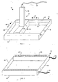
- FIG.1 is a perspective view of an exemplary embodiment of an orientation device 50 particularly suitable for orienting or positioning and immobilizing soft tissue such as the breast or an area of the breast.
- the orientation device 50 generally comprises a frame 52 defining an opening to allow imaging of the area of soft tissue therethrough using an imaging apparatus 54 such as an ultrasound transducer.
- an imaging apparatus 54 such as an ultrasound transducer.
- the imaging apparatus 54 preferably includes a probe 56, a handle 58, and a transmission mechanism 60 for transmitting image data to a computer system (not shown) for data processing and display, for example.
- the transmission mechanism 60 may be a cable connection, as shown, wireless, or any other suitable mechanism.
- the probe 56 is positioned within the opening of the frame 52.
- the imaging apparatus 54 may be positioned outside of the frame 52 such that the imaging beams or energy transmitted and/or received by the imaging apparatus 54 pass through the opening of the frame 52 to allow imaging of the area of soft tissue therethrough or that the imaging beams or energy transmitted may pass underneath the opening of the frame 52 or through the frame 52 to allow imaging of the soft tissue beneath the opening of the frame 52.
- Such a configuration may be employed, for example, when imaging with a MRI (magnetic resonance imaging), CT (computed tomography), PET (positron emission tomography), nuclear medicine, or X-ray imaging device.
- the imaging apparatus 54 may be configured to produce three-dimensional images of the area of soft tissue.
- the frame 52 may comprise two generally parallel cross members 62 along its length in the X direction 64 and two connecting strips 66 along its width in the Y direction 68.
- the connecting strips 66 connect the two parallel cross members 62 to form a generally rectangular frame 52.
- the cross members 62 and connecting strips 66 may be made of any suitable material or combination of materials such as plastics, metals, or ceramics. Although shown as separate components, the cross members 62 and connecting strips 66 may be integrally formed.
- FIG. 2 is a bottom view of the frame 52 illustrating, as an example, vacuum ports 80 for facilitating attachment of the orientation device to the breast or other area being examined. As is evident, where vacuum is used, the vacuum ports are preferably provided on surfaces of the cross members 62 that contact the skin or soft tissue of the patient.
- the frame 52 is connected to an external vacuum source (not shown) using vacuum tubes 81.
- the adhesive is preferably applied on surfaces of the cross members 62 that contact the skin of the patient.
- the cross members 62 provide greater surface area than the connecting strips 66.
- the hooks are preferably provided along at least a portion of the perimeter of the frame 52.
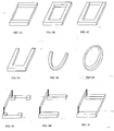
- FIGS. 3A-3I are perspective views illustrating various other exemplary configurations of the frame.
- the frame may provide cross members on three or four sides of the frame and only one or no connecting strips, respectively.
- a squared or rounded U-shaped frame or an oval frame may be provided.
- the connecting strips may be in the same plane or a different plane relative to the cross members.
- the bottom surface of the frame that contacts the skin of the patient need not be flat but may be contoured as desired to achieve better contact and/or be more securely attached to the skin or soft tissue.
- the imaging apparatus 54 is movable within the frame 52 so that the imaging apparatus 54 can scan the tissue area within the confines of the frame 52.
- the probe 56 has a length approximately equal to the interior width of the frame 52 such that the imaging apparatus 54 is slidably movable within the frame 52 between the cross members 62 along the X direction 64 between the connecting strips 66 while the probe 56 stays generally perpendicular to the cross members 62.
- the frame 52 and/or the imaging apparatus 54 may provide any suitable mechanical mechanism to facilitate movement of the imaging apparatus 54 within the frame 52.
- one or both of the cross members 62 may provide a groove 70 (shown dashed) and one or both ends of the probe 56 may provide a corresponding mating tongue (not shown) that slides within the groove 70.
- the tongue(s) provided by the probe 56 may be retractable and/or pliable, for example, to facilitate insertion of each tongue into the corresponding groove.
- the probe 56 may additionally or alternatively provide clips that secure the probe 56 to the frame 52 on the exterior sides of the cross members 62.
- the frame 52 may provide a holder (not shown) for holding the probe 56 within the frame 52.
- the holder may be movable within the opening of the frame 52 such that when the probe 56 is held by the holder, the probe 56, along with the holder, is movable relative to and within the frame 52. Similar mechanisms may be provided to facilitate movement of the imaging apparatus 54 relative to the frame 52 where the imaging device is positioned outside of the opening of the frame 52.
- the probe 56 may be positioned within the opening of the frame 52 and manually moved within the frame.
- the imaging device 54 need not be confined within the frame, but rather, the imaging device 54 may be positioned and mounted outside of the frame 52 such that the imaging beams or energy transmitted and/or received by the imaging device 54 pass through the opening of the frame 52, through the frame 52, or under the frame 52 to allow imaging of the soft tissue beneath the frame 52.
- Such a configuration may be employed, for example, with MRI, CT, PET, nuclear medicine, or an X-ray imaging device.
- one dimension of the opening is preferably sized in one dimension at least equal to the scanning length of the imaging device 54.
- the length of the frame 52 may be fixed in size or may be adjustable in one or two directions. As shown in FIG. 1 , the interior width of the frame 52 is approximately equal to the length of the probe 56 such that the probe 56 is slidably movable within the frame in the X direction 64. However, the imaging apparatus 54 may be rotated 90° relative to the frame 52 and the frame 52 may be adjusted to have an interior length approximately equal to length of the probe 56 such that the probe 56 is slidably movable within the frame in the Y direction 68.
- the frame 52 may be adjustable in length (X direction 64) by having one or more retractable/extensible portions retractable into and extensible from a fixed portion of the cross members 62.
- one or both connecting strips 66 may be slidable along the inside length of the cross members 62 so as to adjust the length of the frame 52.
- the frame 52 may be additionally or alternatively adjustable in width. Width adjustment of the frame 52 may be provided in any suitable manner such as those described above with respect to length adjustment of the probe 56.
- the connecting strips 66 may provide one or more retractable/extensible portions retractable into and extensible from a fixed portion of the connecting strips 66.
- one or both cross members 62 may be slidable along the length of the connecting strips 66 so as to adjust the width of the frame 52.
- one or both of the cross members 62 may be detachably mounted to the connecting strips 66 such that the detachable cross members 62 can be detached from and remounted to the connecting strips 66 at a different location.
- adjustment of the length and/or width of the frame 52 may be provided in any suitable manner. For example, rather than adjusting the dimensions of the frame 52, the size of the probe 56 may be adjusted, the probe 56 may be placed inside an adaptor and positioned within the frame 52, or the probe may be replaced with a different sized probe.
- orientation device 50 is for positioning, immobilizing, and ultrasonically imaging an area of the breast and optionally performing a biopsy or other tissue separation and extraction procedure guided by the ultrasound imaging of the internal breast anatomy.
- the biopsy preferably includes the removal of a lesion or part of the lesion.
- Another preferred use of the orientation device 50 is the positioning, immobilizing, and ultrasonically imaging an area of the breast to perform excision of a cancerous lesion. This preferably includes the removal of the cancerous lesion as well as any extension of the cancer within the affected duct or ducts to include an entire lobe of the breast or portion of a lobe.
- the interior dimensions of the frame 52 are preferably 5-10 cm in length and 4-8 cm in width.
- Linear array ultrasound transducers used for breast imaging are typically 4 cm in length although other sizes, typically 4-8 cm, may be employed.
- the imaging plane for the ultrasound transducer is typically approximately 1 mm in width.
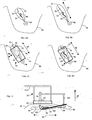
- FIGS. 4A-4D illustrate a lesion 94 that has developed within a breast 90 and positioning and securing of the orientation device 50 to immobilize and scan the area of the breast 90 containing the lesion 94.
- FIG. 4A is a schematic illustrating the lesion 94 in a duct 92 of the-breast 90.
- the lesion 94 has developed in the duct 92 of a lobe 93 and a lesion extension 95 has grown within the duct 92 towards the nipple/areolar complex 98.
- the area of soft tissue containing the lobe 93 is stretched (e.g., manually) as shown in FIG.
- the area of soft tissue is preferably stretched in the direction 64 prior to placement of the frame for better imaging and targeting of the lesion and/or duct, for example.
- FIG. 4C is a schematic illustrating the frame 52 secured to the breast 90 to immobilize and maintain the orientation of the area of soft tissue in the stretched state.
- the frame 52 is generally positioned over the area of soft tissue containing the duct 92 and the lobe 93.
- the portion of the duct 92 not under the frame 52 has been released from being stretched and thus has returned to its natural state as it is no longer stretched or straightened.
- the portion of the duct 92 under the frame 52 is maintained in the stretched and straightened orientation.
- the probe 56 is positioned within the frame 52 so as to image the duct 92, the lobe 93, and/or the lesion 94.
- the lesion 94 is hidden under the probe 56 in FIG. 4C .
- the probe 56 is positioned generally parallel to the duct 92 and perpendicular to the connecting strips 66 such that the probe 56 may move in the direction 64 generally parallel to the duct 92 or in the direction 68 generally perpendicular to the duct 92.
- the probe 56 may also be angled relative to the underlying soft tissue to change the image plane without moving the probe in any one direction.
- the probe 56 may be positioned in any direction in relation to the lesion 94, duct 92, or lobe 93.
- the probe 56 is positioned in one of two ways within the frame 52 depending on, for example, the desired scan path of the probe 56.
- the probe 56 is positioned in the configuration shown in FIG. 4C during insertion and positioning of a tissue separation device near the lesion 94 while the probe 56 is positioned in the configuration shown in FIG. 4D once the tissue separation device is properly positioned.
- FIG. 4D is a schematic illustrating the probe 56 positioned generally parallel to the connecting strips 66 and perpendicular to the duct 92 such that the probe 56 may move in the direction 64 generally along the length of the duct 92.
- the probe 56 may be moved in unison with the tissue separation device performing a biopsy guided by the ultrasound imaging of the internal breast anatomy.
- the probe 56 is preferably moved in unison with the tissue separation device in order to maintain at least a portion of the tissue separation device within the imaging plane of the probe 56 as the tissue separation device is moved, i.e., during the tissue separation procedure.
- FIG. 5 is a schematic illustrating the stabilizing holder device 50 used in conjunction with an exemplary tissue separation device 100 and a lift member 110.
- the tissue, separation device 100 is inserted through an incision 104 in the breast near the orientation device 50 and the lesion 94 and preferably at the border of the nipple/areolar complex 98.
- a separation or working end 102 of the tissue separation device 100 may be positioned within the breast in preparation for separating the lesion 94 from the surrounding tissue, guided using ultrasound scanning with the probe 56.
- the working end 102 of the tissue separation device 100 may be a cutting loop, for example, and may be energized with radio frequency (RF) or other sources of energy or may be a sharp edge.
- RF radio frequency
- the probe 56 may help guide the tissue separation device 100 during separation of the lesion by moving in unison with the working end 102 such that the working end 102 is continuously within the imaging plane of the probe 56 during the tissue separation process.
- a connector 106 may connect the probe 56 to the tissue separation device 100.
- the connector 106 may assume any suitable configuration and may be attached to the probe 56 via the handle 58, for example.
- the area of soft tissue is preferably stretched in the direction 64 prior to securing the frame 52.
- the positioning in the direction 64 straightens the duct 92 in the area of soft tissue to facilitate imaging and tissue separation.
- the area of soft tissue may be positioned in the desired orientation after the frame 52 is secured by adjusting the frame in one or more dimensions.
- the area of soft tissue may be positioned in the desired orientation by widening and/or lengthening the frame 52 to thereby stretch the area of soft tissue in one or more directions.
- the breast is also preferably lifted away from the chest wall in direction 69, e.g., approximately 1 to 10 cm. Such positioning by lifting increases the distance between the lesion 94 and/or duct 92 and the overlying skin and underlying chest wall which provides traction and counter traction to enhance and improve the tissue separation procedure.
- the lifting may be achieved with the use of a lift member 110 attached on one end to the frame 52 of the orientation device 50 and attached on the other end to a stationary anchoring structure (not shown).
- the lift member 110 lifts the orientation device 50, e.g. 1 to 10 cm, in order to stretch the area of soft tissue in a direction away from the underlying structures. For example, lifting the lift member 110 may stretch the area of the breast away from the chest wall.
- the stationary object to which one end of the lift member 110 is attached may be a bed or a table, for example, and provides anchoring support and leverage for the lift member 110.
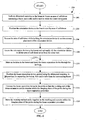
- FIG. 6 is a flowchart illustrating an example-of an imaging and tissue separation process 200 employing the orientation device.
- ultrasound scanning preferably axial ductal scanning
- this step is performed free hand, without using the orientation device 50.
- the axial ductal ultrasound scanning is preferably performed prior to the procedure to identify and delineate the lesion, the affected duct(s) and/or the lobe, the position of the lesion within the duct and/or lobe, and the possibility of other lesions within the affected lobe (e.g. multifocal cancer) and/or spread within the duct(s).
- the ultrasound imaging method may be enhanced with the use of ultrasound contrast agent, such as described in US 2003 01 05402
- the orientation device is positioned on the breast of the patient over the area of soft tissue containing the lesion, duct(s), and/or lobe at step 204.
- the area of the breast over which the orientation device is positioned is preferably manually stretched in the desired direction to straighten the duct(s) and/or lobe just prior to positioning the orientation device thereon.
- the orientation device and the ultrasound transducer may be positioned relative to the duct or lobe similar to that shown in FIG. 4C .
- the length of the frame of the device is generally positioned over the length of the duct or lobe while the length of the probe is positioned generally parallel to the length of the duct or lobe such that the probe may move in a direction generally parallel to the duct or lobe.
- Either the same or a different ultrasound transducer may be used in the orientation device as that used in step 202.
- the orientation device may be manually held in place while a re-scanning of the area of soft tissue is performed to ensure correct placement of the orientation device.
- the orientation device is then secured to the breast with vacuum, adhesives, and/or hooks or clips and may be raised using a lift member so as to stretch the area of soft tissue in a direction away from the chest wall.
- a tissue separation device is inserted through an incision in the breast.
- the incision is made in relatively close proximity to the lesion, duct(s), and/or lobe in which the tissue separation procedure is to be performed and outside of the area held by the orientation device, for example, at the border of the nipple/areolar complex.
- the tissue separation device may be, for example, a biopsy needle or a tissue severing device such as those described in US 2003 0163129 .
- the tissue separation device guided using ultrasound scanning, is positioned in preparation for separating the lesion, duct(s), and/or lobe from the surrounding tissue.
- the entire lesion, part or all of the associated duct or ducts, or the entire lobe or a part of the lobe containing the lesion is targeted.
- the probe is rotated within the frame of the orientation device relative to the targeted tissue and to the frame similar to that shown in FIG. 4D .
- the frame of the orientation device remains in the same orientation relative to the targeted tissue while maintaining the position and immobilization of the desired area of the breast, i.e.
- the length of the frame is generally oriented over the length of the duct(s) or lobe.
- the length of the probe is oriented generally perpendicular to the length of the duct(s) or lobe such that the probe may move in a direction generally parallel to the duct(s) or lobe. Such orientation of the probe allows the width of the lesion, duct(s), lobe or other area of interest to be within the imaging plane.
- the orientation device is fixed to facilitate in positioning, immobilizing, and imaging of the area of soft tissue and guiding the tissue separation procedure.
- securing of the orientation device to the breast prevents movement of the area of soft tissue relative to the probe, thereby ensuring a more accurate and effective scanning, lesion targeting, and tissue separation procedure.
- the tissue separation device may be connected to the probe such that once the tissue separation device is aligned in the imaging plane of the probe, the working end of the tissue separation device will remain within the imaging plane during the tissue separation procedure.
- connecting the tissue separation device to the probe helps guide the tissue separation device by maintaining the tissue separation device in the same orientation as the probe.
- the working end and the probe are moved together so that the working end remains within the imaging plane of the probe during the tissue separation procedure.
- the working end is a cutting ring
- the ring may be raised to encircle the lesion, duct(s), lobe, or other targeted tissue and pulled or pushed to cut around the targeted tissue for tissue separation.
- the cutter completes the cut around the targeted tissue, the process 200 is complete.
- the severed tissue may be captured in a tissue collection device to facilitate removal from the patient.
- orientation device and the imaging and tissue separation process guided using the orientation device provide enhanced accuracy and thus effectiveness in the imaging and the procedure.
Abstract
Description
- The present invention relates generally to systems for positioning and maintaining a region of soft tissue in a desired orientation to facilitate imaging, and the performance of a procedure in the soft tissue. More specifically, systems and methods for the orientation of soft tissue such as breast tissue for enhanced accuracy of imaging and/or procedures such as a biopsy or excision are disclosed.
- Before a lesion within-breast tissue of a living subject can be properly targeted and treated, the breast tissue is often imaged in order to locate and delineate the lesion. Once the location of the lesion is determined, it is often necessary to insert an invasive device such as a guide wire into the breast tissue to target the lesion. Ideally, the tip of the guide wire is placed near the lesion within the breast tissue. The guide wire helps direct the surgeon to the lesion during an operative procedure.
- There are several disadvantages in such a procedure using the guide wire. For example, using a guide wire is a cumbersome and time consuming process. The pre-operative guide wire placement is typically performed in a separate department from the operative procedure, often adding hours of time. In addition, the guide wire can move within the breast before the operative-procedure is conducted. Further, only a rough estimate of the actual location of the tip of the guide wire within the breast tissue can be made prior to making the skin incision which often leads to inaccurate or excessive tissue excision.
- An imaging process at the time of the operative procedure would eliminate the need for pre-operative guide wire placement and would allow more accurate targeting of the lesion.
- From the start of the imaging and localization process to locate the lesion to the completion of the procedure to address the lesion, the breast tissue should be optimally positioned and maintained in the desired orientation during the entire process. For example, if the breast tissue moves after localization of the lesion by imaging and before the procedure, the region of the procedure may not be that of the lesion. Thus, minimally invasive devices and procedures on the breast that require imaging often require breast immobilization.
- Conventional breast immobilization devices have resulted from the techniques of mammography in which the breast is compressed and held immobile between two rigid and parallel plates. After using mammography to localize the lesion within the breast, the breast remains compressed and immobilized between the two compression plates to provide a platform from which to conduct the diagnostic procedure. Thus the breast stays in compression during the entire localization and biopsy procedures. However, there are a number of disadvantages with the use of parallel compression plates. For example, such a breast compression device and associated procedures are uncomfortable, awkward, and painful for the patient. In particular, the patient is often required to assume an uncomfortable position to fit the breast between the plates and the degree of compression necessary to properly stabilize the breast in this manner is great. In addition, compression distorts the internal structures of the breast, jeopardizing the accuracy and effectiveness of the procedure. Conventional breast immobilization devices also do not orient the tissue in a manner conducive to providing an optimal site for a skin incision to perform the procedure.
- Sonographic localization of the lesion is another method used to target lesions in the breast tissue for sampling or excision. For example, a physician may use ultrasound to guide a fine needle aspiration, core biopsy, or vacuum assisted core biopsy. In such a procedure, rather than compressing the breast, an ultrasound transducer is typically used to image the breast to locate the lesion. In a biopsy guided by ultrasound, the physician needs to simultaneously stabilize the breast, hold the ultrasound transducer, and perform the biopsy accurately enough to obtain tissue from the lesion while maintaining the needle within the imaging plane of the ultrasound transducer. It is difficult for the physician to have an assistant help perform the procedure because the ultrasound transducer and biopsy device need to be in precise alignment in order for the biopsy device to be visualized on the ultrasound monitor. Furthermore, the breast moves in response to even slight pressure or patient movement due to, for example, coughing or even the patient's heartbeat. Such movement may make imaging and targeting of a lesion during a procedure in the breast difficult and may also cause the biopsy device and ultrasound transducer to misalign.
- Nonetheless, such sonographic imaging and procedures on an uncompressed breast would generally be more comfortable for the patient, may allow more entry site choices for the surgical device, and may provide for excising of tissue from the breast in its natural state. One example of an ultrasound examination of the breast is described in
U.S. Patent No. 5,709,206 to Teboul . In particular, Teboul describes utilizing ultrasound examination of the internal breast anatomy to study the lesion and its relation to the duct in which it developed. By using axial ductal ultrasound scanning, identification and characterization of the lesion, position within the lobe, and the possibility of spread within the duct or ducts and/or the identification other lesions within the affected lobe (e.g. multifocal cancer) can be delineated prior to a biopsy or treatment procedure. In order to facilitate identification and characterization of the ducts, the ducts should ideally be in a straight alignment with the length of the ultrasound transducer such that as much of the length of the duct as possible is within the imaging plane of the transducer. The ducts can be straightened manually by applying slight pressure using a transducer with a length of about 6 cm. Maintaining the ducts as straight as possible during an invasive procedure would facilitate the accuracy and ease of the procedure. - Accordingly, there is a need for a system and method for orienting the soft tissue in an area of the breast or other soft tissue and for maintaining or immobilizing the soft tissue in the desired orientation that enhance accuracy of imaging and/or procedures. Ideally, the system and method allow imaging of a procedure as it is being performed for improved effectiveness and accuracy of the procedure.
-
EP-A-0 331 348 (Hon et al ) discloses an ultrasound transducer holder for particular application in obtaining the fetal heart rate of a pregnant patient. The holder is a flexible disc with a central support member and a central opening for receiving an ultrasonic transducer. The holder is adhesively attached to the patient, allowing the transducer to be held in a desired orientation on the patient's body. - A surgical retractor is known from
US 5, 813, 978 . - Systems and methods for the orientation of soft tissue such as breast tissue for enhanced accuracy of imaging and/or procedures such as a biopsy or excision are disclosed. It should be appreciated that the present invention can be implemented in numerous ways, including as a process, an apparatus, a system, a device, or a method. Several inventive embodiments of the present invention are described below.
- According to the invention, there is provided an apparatus for orienting and maintaining the orientation of soft tissue, as defined in claim 1.
- The imaging device may transmit a transmission imaging energy for image scanning of the area of soft tissue, the frame and opening being configured such that the transmission imaging energy passes through the opening to facilitate the image scanning of the area of soft tissue.
- The imaging device may transmit a transmission imaging energy for image scanning of the area of soft tissue, the frame and opening being configured such that the transmission imaging energy passes beneath or through the frame to facilitate the image scanning of the area of soft tissue.
- The imaging device may transmit a transmission imaging energy for image scanning of the area of soft tissue, the imaging device being configured such that the transmission imaging energy is movable relative to the frame.
- Preferably, the imaging device may be in communication with a system for processing image data received from the imaging device and for displaying the processed image data. More preferably, the processed image data is adapted to show a three-dimensional image of the area of soft tissue.
- The imaging device may be one of ultrasound, magnetic resonance imaging, computed tomography, positron emission tomography, x-ray imaging, and nuclear medicine imaging.
- Preferably, the imaging device includes a probe configured to be movable in the opening. More preferably, the probe of the imaging device is an ultrasound transducer. Still more preferably, the probe has a scanning length, and wherein the opening has a first dimension in a first direction at least equal to the scanning length of the probe to facilitate guiding movement of the scanning within the opening in the first direction or in a second direction perpendicular to the first direction. Still yet more preferably, the opening has a second dimension in the second direction, the frame being adjustable in the second direction so that the opening has a size in the second direction at least equal to the scanning length of the probe to facilitate guiding movement of the scanning within the opening in the first direction or in the second direction. The frame may be adjustable in size in the first direction.
- Preferably, the frame has a fixed portion and a retractable and extensible portion that is retractable into and extensible from the fixed portion to provide adjustability in size of the frame.
- Preferably, the frame includes a guide member on a surface thereof to guide the probe in its movement along the guide member. More preferably, the guide member is one of a tongue and a groove, and the probe provides a corresponding one of a groove and a tongue, respectively, for mating with the guide member of the frame to facilitate guiding movement of the probe along the frame. Still more preferably, the guide member is a holder for the probe, the holder fitting within the opening of the frame and moveable within the opening to facilitate guiding movement of the probe relative to the frame,
- The attachment mechanism may includes vacuum ports on the frame connectable to a vacuum source, said vacuum ports facilitating attaching the frame to the attachment area.
- The attachment mechanism may be an application of adhesive to a surface of the frame to facilitate attaching the frame to the attachment area.
- The attachment mechanism may include clips adapted to be clipped to the attachment area to facilitate in attaching the frame to the attachment area.
Preferably, the apparatus further includes a lift member connected to the frame, the lift member being anchored and adapted to lift the frame and at least one of the skin surface and area of soft tissue to which the frame is attached. More preferably, the lift member is adapted to lift the frame and at least one of the skin surface and the area of soft tissue approximately 1 to 10 cm. - Preferably, the apparatus further includes a connector for connecting the imaging device to a tissue separation device, the connector facilitating the maintaining of at least a portion of the tissue separation device in an imaging plane of the imaging device. More preferably, the imaging device includes a probe configured to be movable in the opening, and the imaging device further includes a handle to facilitate positioning of the probe relative to the frame, the connector being connected to the handle of the imaging device. Still more preferably, the portion of the tissue separation device (100) imaged by the imaging device is a tissue separator portion (102) of the tissue separation device.
- The apparatus provides an operative framing system that can hold an imaging probe, e.g. an ultrasound transducer, while maintaining the orientation of the area of soft tissue to prevent undesirable movement. Such apparatus improves imaging and the tissue separation procedure by positioning the area of soft tissue in a better geometric arrangement, for example, stretching the tissue along the direction of the duct(s) to straighten the duct(s). Furthermore, the apparatus additionally improves the tissue separation procedure by stretching the soft tissue in another direction or directions, for example, by lifting the breast away from the chest wall, to provide traction and counter traction. Once the soft tissue area of interest is in the desired orientation, the apparatus immobilizes and keeps the area of interest in the desired orientation during imaging and the tissue separation procedure.
- These and other features and advantages of the present invention will be presented in more detail in the following detailed description and the accompanying figures which illustrate by way of example the principles of the invention.
- The present invention will be readily understood by the following detailed description in conjunction with the accompanying drawings, wherein like reference numerals designate like structural elements, and in which:
- FIG. is a perspective view of an exemplary embodiment of a stabilizing holder device particularly suitable for stabilizing soft tissue such as the breast or an area of the breast;
-
FIG. 2 is a bottom view of a frame of the stabilizing holder device illustrating, as an example, vacuum ports for facilitating attachment of the stabilizing holder device to the breast or other area being examined; -
FIGS. 3A-3I are perspective views illustrating various exemplary configurations of the frame of the stabilizing holder device; -
FIGS. 4A is a schematic illustrating a lesion in a duct or a breast; -
FIG. 4B is a schematic illustrating effect of stretching the duct and the lobe in which the duct is located; -
FIG. 4C is a schematic illustrating the positioning of the probe within the frame secured to the breast to maintain the orientation of the breast in order to image the duct, the lobe, and/or the lesion; -
FIG. 4D is a schematic illustrating an alternative positioning of the probe within the frame in order to image the duct, the lobe, and/or the lesion; -
FIG. 5 is a schematic illustrating the stabilizing holder device used in conjunction with a tissue separation device and a lift member; and -
FIG. 6 is a flowchart illustrating an imaging and tissue separation process employing the stabilizing holder device. - Systems and methods for the orientation of soft tissue such as breast tissue for enhanced accuracy of imaging-and/or procedures such as a biopsy or excision are disclosed. The following description is presented to enable any person skilled in the art to make and use the invention. Descriptions of specific embodiments and applications are provided only as examples and various modifications will be readily apparent to those skilled in the art. The general principles defined herein may be applied to other embodiments and application For purpose of clarity, details relating to technical material that is known in the technical fields related to the invention have not been described in detail so as not to unnecessarily obscure the present invention. The present invention is defined in claim 1.
-
FIG.1 is a perspective view of an exemplary embodiment of anorientation device 50 particularly suitable for orienting or positioning and immobilizing soft tissue such as the breast or an area of the breast. Although the preferred use is for imaging and procedures in the breast, as given by example, the tissue site of use is not limited to the breast. The embodiments and methods described herein can be used in and not limited to other tissues such as other subcutaneous tissue, heart, and liver. Theorientation device 50 generally comprises aframe 52 defining an opening to allow imaging of the area of soft tissue therethrough using animaging apparatus 54 such as an ultrasound transducer. Although the examples presented herein utilize ultrasound, it is to be understood that any other suitable imaging methods may be utilized. Theimaging apparatus 54 preferably includes aprobe 56, ahandle 58, and atransmission mechanism 60 for transmitting image data to a computer system (not shown) for data processing and display, for example. Thetransmission mechanism 60 may be a cable connection, as shown, wireless, or any other suitable mechanism. - In the embodiment shown in
FIG. 1 , theprobe 56 is positioned within the opening of theframe 52. However, it is to be understood that theimaging apparatus 54 may be positioned outside of theframe 52 such that the imaging beams or energy transmitted and/or received by theimaging apparatus 54 pass through the opening of theframe 52 to allow imaging of the area of soft tissue therethrough or that the imaging beams or energy transmitted may pass underneath the opening of theframe 52 or through theframe 52 to allow imaging of the soft tissue beneath the opening of theframe 52. Such a configuration may be employed, for example, when imaging with a MRI (magnetic resonance imaging), CT (computed tomography), PET (positron emission tomography), nuclear medicine, or X-ray imaging device. In a further embodiment, theimaging apparatus 54 may be configured to produce three-dimensional images of the area of soft tissue. - The
frame 52 may comprise two generallyparallel cross members 62 along its length in theX direction 64 and two connectingstrips 66 along its width in theY direction 68. The connecting strips 66 connect the twoparallel cross members 62 to form a generallyrectangular frame 52. Thecross members 62 and connectingstrips 66 may be made of any suitable material or combination of materials such as plastics, metals, or ceramics. Although shown as separate components, thecross members 62 and connectingstrips 66 may be integrally formed. - The
cross members 62 and/or connectingstrips 66 preferably provide a mechanism to attach or adhere theframe 52 to the breast or other area being examined. Once theframe 52 is attached to the desired area, theframe 52 stays fixed in place relative to the skin or soft tissue to which it is attached. Examples of suitable attachment mechanisms include adhesive, vacuum, and/or hooks or clips.FIG. 2 is a bottom view of theframe 52 illustrating, as an example,vacuum ports 80 for facilitating attachment of the orientation device to the breast or other area being examined. As is evident, where vacuum is used, the vacuum ports are preferably provided on surfaces of thecross members 62 that contact the skin or soft tissue of the patient. Theframe 52 is connected to an external vacuum source (not shown) usingvacuum tubes 81. Similarly, where an adhesive is used, the adhesive is preferably applied on surfaces of thecross members 62 that contact the skin of the patient. Thecross members 62 provide greater surface area than the connecting strips 66. Where hooks are utilized, the hooks are preferably provided along at least a portion of the perimeter of theframe 52. - In the embodiment shown in
FIG. 1 , thecross members 62 provide more dimensional stability for theframe 52 than the connectingstrips 66 due to their relative sizes.FIGS. 3A-3I are perspective views illustrating various other exemplary configurations of the frame. For example, the frame may provide cross members on three or four sides of the frame and only one or no connecting strips, respectively. In addition, there may be multiple cross members linked together by connecting strips. As another example, a squared or rounded U-shaped frame or an oval frame may be provided. The connecting strips may be in the same plane or a different plane relative to the cross members. In addition, the bottom surface of the frame that contacts the skin of the patient need not be flat but may be contoured as desired to achieve better contact and/or be more securely attached to the skin or soft tissue. - Referring again to
FIG. 1 , theimaging apparatus 54 is movable within theframe 52 so that theimaging apparatus 54 can scan the tissue area within the confines of theframe 52. In the configuration shown inFIG. 1 , theprobe 56 has a length approximately equal to the interior width of theframe 52 such that theimaging apparatus 54 is slidably movable within theframe 52 between thecross members 62 along theX direction 64 between the connectingstrips 66 while theprobe 56 stays generally perpendicular to thecross members 62. - It is-noted that the
frame 52 and/or theimaging apparatus 54 may provide any suitable mechanical mechanism to facilitate movement of theimaging apparatus 54 within theframe 52. For example, one or both of thecross members 62 may provide a groove 70 (shown dashed) and one or both ends of theprobe 56 may provide a corresponding mating tongue (not shown) that slides within thegroove 70. The tongue(s) provided by theprobe 56 may be retractable and/or pliable, for example, to facilitate insertion of each tongue into the corresponding groove. As another example, theprobe 56 may additionally or alternatively provide clips that secure theprobe 56 to theframe 52 on the exterior sides of thecross members 62. As a further example, theframe 52 may provide a holder (not shown) for holding theprobe 56 within theframe 52. The holder may be movable within the opening of theframe 52 such that when theprobe 56 is held by the holder, theprobe 56, along with the holder, is movable relative to and within theframe 52. Similar mechanisms may be provided to facilitate movement of theimaging apparatus 54 relative to theframe 52 where the imaging device is positioned outside of the opening of theframe 52. - As noted above, the
probe 56 may be positioned within the opening of theframe 52 and manually moved within the frame. However, theimaging device 54 need not be confined within the frame, but rather, theimaging device 54 may be positioned and mounted outside of theframe 52 such that the imaging beams or energy transmitted and/or received by theimaging device 54 pass through the opening of theframe 52, through theframe 52, or under theframe 52 to allow imaging of the soft tissue beneath theframe 52. Such a configuration may be employed, for example, with MRI, CT, PET, nuclear medicine, or an X-ray imaging device. With the scanning energy rather than the probe being within the opening of theframe 52, one dimension of the opening is preferably sized in one dimension at least equal to the scanning length of theimaging device 54. - The length of the
frame 52 may be fixed in size or may be adjustable in one or two directions. As shown inFIG. 1 , the interior width of theframe 52 is approximately equal to the length of theprobe 56 such that theprobe 56 is slidably movable within the frame in theX direction 64. However, theimaging apparatus 54 may be rotated 90° relative to theframe 52 and theframe 52 may be adjusted to have an interior length approximately equal to length of theprobe 56 such that theprobe 56 is slidably movable within the frame in theY direction 68. - In one embodiment, the
frame 52 may be adjustable in length (X direction 64) by having one or more retractable/extensible portions retractable into and extensible from a fixed portion of thecross members 62. Alternatively or additionally, one or both connectingstrips 66 may be slidable along the inside length of thecross members 62 so as to adjust the length of theframe 52. Similarly, theframe 52 may be additionally or alternatively adjustable in width. Width adjustment of theframe 52 may be provided in any suitable manner such as those described above with respect to length adjustment of theprobe 56. For example, the connectingstrips 66 may provide one or more retractable/extensible portions retractable into and extensible from a fixed portion of the connecting strips 66. Alternatively or additionally, one or bothcross members 62 may be slidable along the length of the connectingstrips 66 so as to adjust the width of theframe 52. As yet another example, one or both of thecross members 62 may be detachably mounted to the connectingstrips 66 such that thedetachable cross members 62 can be detached from and remounted to the connectingstrips 66 at a different location. Although specific examples of length and width adjustments of theframe 52 are presented herein, adjustment of the length and/or width of theframe 52 may be provided in any suitable manner. For example, rather than adjusting the dimensions of theframe 52, the size of theprobe 56 may be adjusted, theprobe 56 may be placed inside an adaptor and positioned within theframe 52, or the probe may be replaced with a different sized probe. - One preferred use of the
orientation device 50 is for positioning, immobilizing, and ultrasonically imaging an area of the breast and optionally performing a biopsy or other tissue separation and extraction procedure guided by the ultrasound imaging of the internal breast anatomy. The biopsy preferably includes the removal of a lesion or part of the lesion. Another preferred use of theorientation device 50 is the positioning, immobilizing, and ultrasonically imaging an area of the breast to perform excision of a cancerous lesion. This preferably includes the removal of the cancerous lesion as well as any extension of the cancer within the affected duct or ducts to include an entire lobe of the breast or portion of a lobe. - To encompass the entire cancerous lesion and possible extension of cancer-within the associated duct or ducts, the interior dimensions of the
frame 52 are preferably 5-10 cm in length and 4-8 cm in width. Linear array ultrasound transducers used for breast imaging are typically 4 cm in length although other sizes, typically 4-8 cm, may be employed. Moreover, the imaging plane for the ultrasound transducer is typically approximately 1 mm in width. -
FIGS. 4A-4D illustrate alesion 94 that has developed within abreast 90 and positioning and securing of theorientation device 50 to immobilize and scan the area of thebreast 90 containing thelesion 94. In particular,FIG. 4A is a schematic illustrating thelesion 94 in aduct 92 of the-breast 90. As shown, thelesion 94 has developed in theduct 92 of alobe 93 and alesion extension 95 has grown within theduct 92 towards the nipple/areolar complex 98. Preferably, prior to attaching the frame to thebreast 90, the area of soft tissue containing thelobe 93 is stretched (e.g., manually) as shown inFIG. 4B so that theduct 92 and thelobe 93 containing theduct 92 are elongated to straighten theduct 92. In particular, the area of soft tissue is preferably stretched in thedirection 64 prior to placement of the frame for better imaging and targeting of the lesion and/or duct, for example. -
FIG. 4C is a schematic illustrating theframe 52 secured to thebreast 90 to immobilize and maintain the orientation of the area of soft tissue in the stretched state. As shown, theframe 52 is generally positioned over the area of soft tissue containing theduct 92 and thelobe 93. In addition, the portion of theduct 92 not under theframe 52 has been released from being stretched and thus has returned to its natural state as it is no longer stretched or straightened. In contrast, the portion of theduct 92 under theframe 52 is maintained in the stretched and straightened orientation. - The
probe 56 is positioned within theframe 52 so as to image theduct 92, thelobe 93, and/or thelesion 94. Thelesion 94 is hidden under theprobe 56 inFIG. 4C . As shown, theprobe 56 is positioned generally parallel to theduct 92 and perpendicular to the connectingstrips 66 such that theprobe 56 may move in thedirection 64 generally parallel to theduct 92 or in thedirection 68 generally perpendicular to theduct 92. Theprobe 56 may also be angled relative to the underlying soft tissue to change the image plane without moving the probe in any one direction. - As is evident, the
probe 56 may be positioned in any direction in relation to thelesion 94,duct 92, orlobe 93. Typically, theprobe 56 is positioned in one of two ways within theframe 52 depending on, for example, the desired scan path of theprobe 56. For example, theprobe 56 is positioned in the configuration shown inFIG. 4C during insertion and positioning of a tissue separation device near thelesion 94 while theprobe 56 is positioned in the configuration shown inFIG. 4D once the tissue separation device is properly positioned. -
FIG. 4D is a schematic illustrating theprobe 56 positioned generally parallel to the connectingstrips 66 and perpendicular to theduct 92 such that theprobe 56 may move in thedirection 64 generally along the length of theduct 92. For example, theprobe 56 may be moved in unison with the tissue separation device performing a biopsy guided by the ultrasound imaging of the internal breast anatomy. Theprobe 56 is preferably moved in unison with the tissue separation device in order to maintain at least a portion of the tissue separation device within the imaging plane of theprobe 56 as the tissue separation device is moved, i.e., during the tissue separation procedure. -
FIG. 5 is a schematic illustrating the stabilizingholder device 50 used in conjunction with an exemplarytissue separation device 100 and alift member 110. As shown, the tissue,separation device 100 is inserted through anincision 104 in the breast near theorientation device 50 and thelesion 94 and preferably at the border of the nipple/areolar complex 98. A separation or working end 102 of thetissue separation device 100 may be positioned within the breast in preparation for separating thelesion 94 from the surrounding tissue, guided using ultrasound scanning with theprobe 56. The working end 102 of thetissue separation device 100 may be a cutting loop, for example, and may be energized with radio frequency (RF) or other sources of energy or may be a sharp edge. - The
probe 56 may help guide thetissue separation device 100 during separation of the lesion by moving in unison with the working end 102 such that the working end 102 is continuously within the imaging plane of theprobe 56 during the tissue separation process. To facilitate maintaining the working end 102 within the imaging plane of theprobe 56, aconnector 106 may connect theprobe 56 to thetissue separation device 100. Theconnector 106 may assume any suitable configuration and may be attached to theprobe 56 via thehandle 58, for example. - As noted above, for better imaging and targeting of the lesion and/or other tissue, the area of soft tissue is preferably stretched in the
direction 64 prior to securing theframe 52. The positioning in thedirection 64 straightens theduct 92 in the area of soft tissue to facilitate imaging and tissue separation. In an alternative, the area of soft tissue may be positioned in the desired orientation after theframe 52 is secured by adjusting the frame in one or more dimensions. For example, after theframe 52 is secured, the area of soft tissue may be positioned in the desired orientation by widening and/or lengthening theframe 52 to thereby stretch the area of soft tissue in one or more directions. The breast is also preferably lifted away from the chest wall indirection 69, e.g., approximately 1 to 10 cm. Such positioning by lifting increases the distance between thelesion 94 and/orduct 92 and the overlying skin and underlying chest wall which provides traction and counter traction to enhance and improve the tissue separation procedure. - The lifting may be achieved with the use of a
lift member 110 attached on one end to theframe 52 of theorientation device 50 and attached on the other end to a stationary anchoring structure (not shown). Thelift member 110 lifts theorientation device 50, e.g. 1 to 10 cm, in order to stretch the area of soft tissue in a direction away from the underlying structures. For example, lifting thelift member 110 may stretch the area of the breast away from the chest wall. The stationary object to which one end of thelift member 110 is attached may be a bed or a table, for example, and provides anchoring support and leverage for thelift member 110. -
FIG. 6 is a flowchart illustrating an example-of an imaging andtissue separation process 200 employing the orientation device. Atstep 202, ultrasound scanning, preferably axial ductal scanning, is performed on the breast to locate a targeted tissue, i.e. a lesion and the duct(s) and/or lobe in which the lesion developed. Preferably, this step is performed free hand, without using theorientation device 50. The axial ductal ultrasound scanning is preferably performed prior to the procedure to identify and delineate the lesion, the affected duct(s) and/or the lobe, the position of the lesion within the duct and/or lobe, and the possibility of other lesions within the affected lobe (e.g. multifocal cancer) and/or spread within the duct(s). The ultrasound imaging method may be enhanced with the use of ultrasound contrast agent, such as described in US 2003 01 05402 - Once the lesion, duct(s), and/or lobe in which the lesion developed are located, the orientation device is positioned on the breast of the patient over the area of soft tissue containing the lesion, duct(s), and/or lobe at
step 204. The area of the breast over which the orientation device is positioned is preferably manually stretched in the desired direction to straighten the duct(s) and/or lobe just prior to positioning the orientation device thereon. The orientation device and the ultrasound transducer may be positioned relative to the duct or lobe similar to that shown inFIG. 4C . In other words, the length of the frame of the device is generally positioned over the length of the duct or lobe while the length of the probe is positioned generally parallel to the length of the duct or lobe such that the probe may move in a direction generally parallel to the duct or lobe. Either the same or a different ultrasound transducer may be used in the orientation device as that used instep 202. - At
step 206, the orientation device may be manually held in place while a re-scanning of the area of soft tissue is performed to ensure correct placement of the orientation device. Atstep 208, the orientation device is then secured to the breast with vacuum, adhesives, and/or hooks or clips and may be raised using a lift member so as to stretch the area of soft tissue in a direction away from the chest wall. - At
step 210, a tissue separation device is inserted through an incision in the breast. Preferably the incision is made in relatively close proximity to the lesion, duct(s), and/or lobe in which the tissue separation procedure is to be performed and outside of the area held by the orientation device, for example, at the border of the nipple/areolar complex. The tissue separation device may be, for example, a biopsy needle or a tissue severing device such as those described inUS 2003 0163129 . - At step 12, the tissue separation device, guided using ultrasound scanning, is positioned in preparation for separating the lesion, duct(s), and/or lobe from the surrounding tissue. Preferably, the entire lesion, part or all of the associated duct or ducts, or the entire lobe or a part of the lobe containing the lesion is targeted. Once the tissue separation device is properly positioned within the breast tissue, the probe is rotated within the frame of the orientation device relative to the targeted tissue and to the frame similar to that shown in
FIG. 4D . In other words, the frame of the orientation device remains in the same orientation relative to the targeted tissue while maintaining the position and immobilization of the desired area of the breast, i.e. the length of the frame is generally oriented over the length of the duct(s) or lobe. In addition, the length of the probe is oriented generally perpendicular to the length of the duct(s) or lobe such that the probe may move in a direction generally parallel to the duct(s) or lobe. Such orientation of the probe allows the width of the lesion, duct(s), lobe or other area of interest to be within the imaging plane. - As is evident, once the orientation device is positioned and secured to the breast over the area of soft tissue located in
step 202, the orientation device is fixed to facilitate in positioning, immobilizing, and imaging of the area of soft tissue and guiding the tissue separation procedure. Thus, securing of the orientation device to the breast prevents movement of the area of soft tissue relative to the probe, thereby ensuring a more accurate and effective scanning, lesion targeting, and tissue separation procedure. - At
step 214, the tissue separation device may be connected to the probe such that once the tissue separation device is aligned in the imaging plane of the probe, the working end of the tissue separation device will remain within the imaging plane during the tissue separation procedure. In other words, connecting the tissue separation device to the probe helps guide the tissue separation device by maintaining the tissue separation device in the same orientation as the probe. - At
step 216, the working end and the probe are moved together so that the working end remains within the imaging plane of the probe during the tissue separation procedure. Where the working end is a cutting ring, the ring may be raised to encircle the lesion, duct(s), lobe, or other targeted tissue and pulled or pushed to cut around the targeted tissue for tissue separation. When the cutter completes the cut around the targeted tissue, theprocess 200 is complete. In a further embodiment, the severed tissue may be captured in a tissue collection device to facilitate removal from the patient. - As is evident, the orientation device and the imaging and tissue separation process guided using the orientation device provide enhanced accuracy and thus effectiveness in the imaging and the procedure.
- While the preferred embodiments of the present invention are described and illustrated herein, it will be appreciated that they are merely illustrative and that modifications can be made to these embodiments . Thus, the invention is intended to be defined only in terms of the following claims.
Claims (24)
- An apparatus for orienting and maintaining the orientation of soft tissue, comprising:a frame (52) defining an opening, the frame being configured to orient and immobilize in a stretched state an area of soft tissue positioned on one side of the opening, the frame having parts (62, 66) which are moveable relative to each other to provide adjustability in length and/or width of the frame.an attachment mechanism (80) independent of the adjustability of the frame to secure the frame to an attachment region defined by the area of soft tissue or by a skin surface overlying the area of soft tissue, to facilitate orienting and immobilizing the area of soft tissue; andan imaging device (54) positioned to image the area of soft tissue.
- The apparatus of Claim 1, wherein the imaging device (54) transmits a transmission imaging energy for image scanning of the area of soft tissue, the frame (52) and opening being configured such that the transmission imaging energy passes through the opening to facilitate the image scanning of the area of soft tissue.
- The apparatus of Claim 1, wherein the imaging device (54) transmits a transmission imaging energy for image scanning of the area of soft tissue, the frame (52) and opening being configured such that the transmission imaging energy passes beneath or through said frame to facilitate the image scanning of the area of soft tissue.
- The apparatus of any preceding claim, wherein the imaging device (54) transmits a transmission imaging energy for image scanning of the area of soft tissue, the imaging device being configured such that the transmission imaging energy is movable relative to said frame (52).
- The apparatus of any preceding claim, wherein the imaging device (54) is in communication with a system for processing image data received from the imaging device and for displaying the processed image data.
- The apparatus of Claim 5, wherein the processed image data is adapted to show a three-dimensional image of the area of soft tissue.
- The apparatus of any preceding claim, wherein the imaging device (54) is one of ultrasound, magnetic resonance imaging, computed tomography, positron emission tomography, x-ray imaging, and nuclear medicine imaging.
- The apparatus of any preceding claim, wherein the imaging device (54) includes a probe (56) configured to be movable in said opening.
- The apparatus of Claim 8, wherein the probe (56) of the imaging device (54) is an ultrasound transducer.
- The apparatus of Claim 8 or Claim 9, wherein the probe (56) has a scanning length, and wherein the opening has a first dimension in a first direction at least equal to the scanning length of the probe to facilitate guiding movement of the scanning within the opening in the first direction or in a second direction perpendicular to the first direction.
- The apparatus of Claim 10, wherein the opening has a second dimension in the second direction, the frame (52) being adjustable in the second direction so that the opening has a size in the second direction at least equal to the scanning length of the probe (56) to facilitate guiding movement of the scanning within the opening in the first direction or in the second direction.
- The apparatus of Claim 10, wherein the frame has a fixed portion and a retractable and extensible portion that is retractable into and extensible from the fixed portion to provide adjustability in size of the frame in the second direction.
- The apparatus of Claim 10, wherein the frame (52) is adjustable in size in the first direction.
- The apparatus of Claim 8, wherein the frame (52) includes a guide member (70) on a surface thereof to guide the probe in its movement along the guide member.
- The apparatus of Claim 14, wherein the guide member is one of a tongue and a groove (70), and wherein the probe (56) provides a corresponding one of a groove and a tongue, respectively, for mating with the guide member of the frame to facilitate guiding movement of the probe along the frame.
- The apparatus of Claim 14, wherein the guide member is a holder for the probe (56), said holder fitting within the opening of the frame and moveable within the opening to facilitate guiding movement of the probe relative to the frame.
- The apparatus of any preceding claim, wherein the attachment mechanism comprises vacuum ports (80) on the frame connectable to a vacuum source, said vacuum ports facilitating attaching the frame (52) to the attachment area.
- The apparatus of any preceding claim, wherein the attachment mechanism is an application of adhesive to a surface of the frame (52) to facilitate attaching the frame to the attachment area.
- The apparatus of any preceding claim, wherein the attachment mechanism comprises clips adapted to be clipped to the attachment area to facilitate in attaching the frame to the attachment area.
- The apparatus of any preceding claim, further comprising a lift member (110) connected to the frame (52), the lift member being anchored and adapted to lift the frame and at least one of the skin surface and area of soft tissue to which the frame is attached.
- The apparatus of Claim 20, wherein the lift member (110) is adapted to lift the frame (52) and at least one of the skin surface and the area of soft tissue approximately 1 to 10 cm.
- The apparatus of Claim 1, further comprising a connector (106) for connecting the imaging device (54) to a tissue separation device (100), the connector facilitating the maintaining of at least a portion of the tissue separation device in an imaging plane of the imaging device.
- The apparatus of Claim 22, wherein the imaging device (54) includes a probe (56) configured to be movable in said opening, and wherein the imaging device further includes a handle (58) to facilitate positioning of the probe relative to the frame (52), wherein the connector (106) is connected to the handle of the imaging device.
- The apparatus of Claim 22 and Claim 23, wherein the portion of the tissue separation device (100) imaged by the imaging device is a tissue separator portion (102) of the tissue separation device.
Applications Claiming Priority (3)
| Application Number | Priority Date | Filing Date | Title |
|---|---|---|---|
| US284990 | 2002-10-31 | ||
| US10/284,990 US7149566B2 (en) | 2002-10-31 | 2002-10-31 | Soft tissue orientation and imaging guide systems and methods |
| PCT/US2003/034228 WO2004041093A1 (en) | 2002-10-31 | 2003-10-29 | Soft tissue orientation and imaging guide systems and methods |
Publications (2)
| Publication Number | Publication Date |
|---|---|
| EP1555941A1 EP1555941A1 (en) | 2005-07-27 |
| EP1555941B1 true EP1555941B1 (en) | 2011-03-09 |
Family
ID=32175055
Family Applications (1)
| Application Number | Title | Priority Date | Filing Date |
|---|---|---|---|
| EP03779389A Expired - Lifetime EP1555941B1 (en) | 2002-10-31 | 2003-10-29 | Soft tissue orientation and imaging guide systems |
Country Status (7)
| Country | Link |
|---|---|
| US (2) | US7149566B2 (en) |
| EP (1) | EP1555941B1 (en) |
| JP (1) | JP2006504488A (en) |
| AT (1) | ATE500785T1 (en) |
| AU (1) | AU2003285074A1 (en) |
| DE (1) | DE60336332D1 (en) |
| WO (1) | WO2004041093A1 (en) |
Families Citing this family (25)
| Publication number | Priority date | Publication date | Assignee | Title |
|---|---|---|---|---|
| US7149566B2 (en) * | 2002-10-31 | 2006-12-12 | Manoa Medical, Inc. | Soft tissue orientation and imaging guide systems and methods |
| US9638770B2 (en) | 2004-05-21 | 2017-05-02 | Devicor Medical Products, Inc. | MRI biopsy apparatus incorporating an imageable penetrating portion |
| US7708751B2 (en) * | 2004-05-21 | 2010-05-04 | Ethicon Endo-Surgery, Inc. | MRI biopsy device |
| US8932233B2 (en) | 2004-05-21 | 2015-01-13 | Devicor Medical Products, Inc. | MRI biopsy device |
| US20070238950A1 (en) * | 2006-03-24 | 2007-10-11 | Vija A H | Separate and combined multi-modality diagnostic imaging system |
| US10561394B2 (en) * | 2006-05-02 | 2020-02-18 | U-Systems, Inc. | Ultrasound scanning and ultrasound-assisted biopsy |
| US8376947B2 (en) * | 2008-03-26 | 2013-02-19 | Bioquantetics, Inc. | Application of image-based dynamic ultrasound spectrography (IDUS) in detection and localization of breast microcalcifcation |
| EP2168485A1 (en) * | 2008-09-29 | 2010-03-31 | MIR Medical Imaging Research Holding GmbH | Breast holder for examination device for examination of breasts |
| KR101089743B1 (en) * | 2009-02-27 | 2011-12-07 | 삼성메디슨 주식회사 | Ultrasonic diagnosis device |
| DK200900527A (en) | 2009-04-24 | 2010-10-25 | Region Nordjylland Aalborg Syg | Device for holding an imaging probe and use of such device |
| EP2552322B1 (en) | 2010-03-30 | 2016-11-16 | Martin L. Flatland | Tissue excision device |
| JP5400814B2 (en) * | 2010-11-26 | 2014-01-29 | 富士フイルム株式会社 | Biopsy spacer |
| WO2014138423A1 (en) * | 2013-03-06 | 2014-09-12 | University Of Pittsburgh - Of The Commonwealth System Of Higher Education | Methods and apparatus to measure constitutive relations and fiber orientation of soft tissues |
| KR101510533B1 (en) | 2013-09-25 | 2015-04-08 | 인제대학교 산학협력단 | Renal scan guide device |
| KR102180465B1 (en) * | 2013-11-06 | 2020-11-18 | 삼성메디슨 주식회사 | Supporting device of ultrasound probe, Handfree ultrasound probe comprising the same and Method of operating Handfree ultrasound probe |
| US9687209B2 (en) * | 2014-10-09 | 2017-06-27 | Choon Kee Lee | Invasive device positioning assembly |
| CN108938004A (en) * | 2015-07-13 | 2018-12-07 | 古野电气株式会社 | Probe adapter, ultrasonic imaging apparatus |
| JP6957519B2 (en) * | 2016-02-09 | 2021-11-02 | デルフィヌス メディカル テクノロジーズ, インコーポレイテッド | A system for shaping and positioning tissues |
| CN106725765B (en) * | 2017-01-03 | 2019-04-02 | 沈滨 | A kind of ultrasound guidance breast puncture device |
| KR102033172B1 (en) * | 2017-12-19 | 2019-11-08 | 주식회사 하이로닉 | Handpiece for laser operation and fat reduction apparatus with the same |
| US11234676B2 (en) * | 2018-01-29 | 2022-02-01 | Elekta Ltd. | Probe holder for ultrasound imaging device |
| US11464483B2 (en) | 2019-03-21 | 2022-10-11 | Elekta Limited | Overlay system including a detachable handle |
| CN110037655B (en) * | 2019-04-12 | 2020-07-28 | 北京大学 | Photoacoustic mammary gland imaging device and imaging method thereof |
| US20220096119A1 (en) * | 2020-09-29 | 2022-03-31 | Bard Access Systems, Inc. | Hands-Free Ultrasound Probes, Assemblies, Systems, and Methods |
| CN112568977A (en) * | 2020-11-23 | 2021-03-30 | 河北医科大学第四医院(河北省肿瘤医院) | Auxiliary backing plate for breast puncture biopsy |
Family Cites Families (28)
| Publication number | Priority date | Publication date | Assignee | Title |
|---|---|---|---|---|
| US4347850A (en) * | 1980-03-19 | 1982-09-07 | Indianapolis Center For Advanced Research, Inc. | Direct water coupling device for ultrasound breast scanning in a supine position |
| DE3224412A1 (en) * | 1982-06-30 | 1984-01-05 | Siemens AG, 1000 Berlin und 8000 München | ULTRASONIC TOMOGRAPHER |
| DE3227624A1 (en) | 1982-07-23 | 1984-01-26 | Siemens AG, 1000 Berlin und 8000 München | Device for examining the female breast using ultrasound |
| US4920966A (en) | 1986-10-02 | 1990-05-01 | Hon Edward H | Ultrasound transducer holder |
| US5146923A (en) * | 1986-12-18 | 1992-09-15 | Dhawan Atam P | Apparatus and method for skin lesion examination |
| GB8728150D0 (en) * | 1987-12-02 | 1988-01-06 | Inst Of Neurology Queen Square | Head fixation apparatus |
| US5201742A (en) * | 1991-04-16 | 1993-04-13 | Hasson Harrith M | Support jig for a surgical instrument |
| DE4225001C1 (en) * | 1992-07-29 | 1993-11-18 | Siemens Ag | Stereo-tactic additional device for nuclear spin tomography for investigation of mammary disorders - has two compression plates parallel and displaceable towards one another, between which object for investigation e.g breast is positioned |
| US5333612A (en) * | 1993-08-26 | 1994-08-02 | Wild John J | Volumetric breast interogation device |
| DE4442609C1 (en) * | 1994-11-30 | 1996-08-08 | Siemens Ag | Stereotactic additional device for carrying out pattern-guided biopsy of female breast |
| US5499989A (en) * | 1994-12-22 | 1996-03-19 | Labash; Stephen S. | Breast biopsy apparatus and method of use |
| US5709206A (en) * | 1995-11-27 | 1998-01-20 | Teboul; Michel | Imaging system for breast sonography |
| US6424852B1 (en) | 1996-10-18 | 2002-07-23 | Lucid, Inc. | System for confocal imaging within dermal tissue |
| DE69737720T2 (en) * | 1996-11-29 | 2008-01-10 | London Health Sciences Centre, London | IMPROVED IMAGE PROCESSING METHOD FOR A THREE-DIMENSIONAL IMAGE GENERATION SYSTEM |
| DE19709224C2 (en) * | 1997-03-06 | 2001-07-19 | Siemens Ag | Compression part for a medical compression device and compression device therefor |
| US5855554A (en) * | 1997-03-17 | 1999-01-05 | General Electric Company | Image guided breast lesion localization device |
| WO1999000675A1 (en) * | 1997-06-25 | 1999-01-07 | Life Imaging Systems Inc. | System and method for the dynamic display of three-dimensional image data |
| US6019722A (en) * | 1997-09-17 | 2000-02-01 | Guidant Corporation | Device to permit offpump beating heart coronary bypass surgery |
| US6146377A (en) * | 1998-09-22 | 2000-11-14 | Rubicor Medical, Inc. | Breast stabilization devices and methods |
| CA2287087C (en) * | 1998-10-23 | 2007-12-04 | Ethicon Endo-Surgery, Inc. | Surgical device for the collection of soft tissue |
| US6122542A (en) * | 1998-11-25 | 2000-09-19 | Rubicor Medical, Inc. | Breast stabilization devices and imaging and interventional methods using the same |
| US6406482B1 (en) * | 1999-09-13 | 2002-06-18 | The Ohio State University | Stereotactic apparatus and methods |
| WO2001019233A2 (en) * | 1999-09-14 | 2001-03-22 | Papillon Surgical | Breast bracket |
| US6406424B1 (en) * | 1999-09-16 | 2002-06-18 | Williamson, Iv Warren P. | Tissue stabilizer having an articulating lift element |
| US6254614B1 (en) * | 1999-10-18 | 2001-07-03 | Jerry M. Jesseph | Device and method for improved diagnosis and treatment of cancer |
| US6277083B1 (en) * | 1999-12-27 | 2001-08-21 | Neothermia Corporation | Minimally invasive intact recovery of tissue |
| US6695786B2 (en) | 2001-03-16 | 2004-02-24 | U-Systems, Inc. | Guide and position monitor for invasive medical instrument |
| US7149566B2 (en) * | 2002-10-31 | 2006-12-12 | Manoa Medical, Inc. | Soft tissue orientation and imaging guide systems and methods |
-
2002
- 2002-10-31 US US10/284,990 patent/US7149566B2/en not_active Expired - Fee Related
-
2003
- 2003-10-29 AU AU2003285074A patent/AU2003285074A1/en not_active Abandoned
- 2003-10-29 AT AT03779389T patent/ATE500785T1/en not_active IP Right Cessation
- 2003-10-29 DE DE60336332T patent/DE60336332D1/en not_active Expired - Lifetime
- 2003-10-29 EP EP03779389A patent/EP1555941B1/en not_active Expired - Lifetime
- 2003-10-29 JP JP2004550163A patent/JP2006504488A/en active Pending
- 2003-10-29 WO PCT/US2003/034228 patent/WO2004041093A1/en active Application Filing
-
2006
- 2006-12-12 US US11/637,394 patent/US20070118033A1/en not_active Abandoned
Also Published As
| Publication number | Publication date |
|---|---|
| US20040087851A1 (en) | 2004-05-06 |
| EP1555941A1 (en) | 2005-07-27 |
| US20070118033A1 (en) | 2007-05-24 |
| ATE500785T1 (en) | 2011-03-15 |
| JP2006504488A (en) | 2006-02-09 |
| US7149566B2 (en) | 2006-12-12 |
| DE60336332D1 (en) | 2011-04-21 |
| AU2003285074A1 (en) | 2004-06-07 |
| WO2004041093A1 (en) | 2004-05-21 |
Similar Documents
| Publication | Publication Date | Title |
|---|---|---|
| EP1555941B1 (en) | Soft tissue orientation and imaging guide systems | |
| JP3545294B2 (en) | Breast stabilization device | |
| CA2281045C (en) | Breast stabilization devices and methods | |
| US5682890A (en) | Magnetic resonance stereotactic surgery with exoskeleton tissue stabilization | |
| ES2378351T3 (en) | Image-guided biopsy device | |
| US7937132B2 (en) | Hybrid imaging method to monitor medical device delivery and patient support for use in method | |
| US7769426B2 (en) | Method for using an MRI compatible biopsy device with detachable probe | |
| US8808198B2 (en) | MRI compatible biopsy device with detachable probe | |
| US6569176B2 (en) | Device and method for improved diagnosis and treatment of cancer | |
| US4981142A (en) | Compression device | |
| EP1356773A1 (en) | Localization mechanism for an MRI compatible biopsy device | |
| JP2000512189A (en) | System for surgery, biopsy and resection of tumors or other physical abnormalities | |
| US20040073106A1 (en) | Breast stabilizers having an open lattice structure and imaging methods using same | |
| AU2003200267C1 (en) | Method of imaging a breast | |
| AU2003200266B2 (en) | Method of Stabilising an Uncompressed Breast | |
| EP1820453B1 (en) | An MRI compatible biopsy device with detachable probe | |
| AU2003203755B2 (en) | Breast Stabilization Devices and Imaging and Interventional Methods Using Same | |
| CA2473138A1 (en) | Breast stabilization devices and imaging and interventional methods using same |
Legal Events
| Date | Code | Title | Description |
|---|---|---|---|
| PUAI | Public reference made under article 153(3) epc to a published international application that has entered the european phase |
Free format text: ORIGINAL CODE: 0009012 |
|
| 17P | Request for examination filed |
Effective date: 20050502 |
|
| AK | Designated contracting states |
Kind code of ref document: A1 Designated state(s): AT BE BG CH CY CZ DE DK EE ES FI FR GB GR HU IE IT LI LU MC NL PT RO SE SI SK TR |
|
| AX | Request for extension of the european patent |
Extension state: AL LT LV MK |
|
| DAX | Request for extension of the european patent (deleted) | ||
| RTI1 | Title (correction) |
Free format text: SOFT TISSUE ORIENTATION AND IMAGING GUIDE SYSTEMS |
|
| GRAP | Despatch of communication of intention to grant a patent |
Free format text: ORIGINAL CODE: EPIDOSNIGR1 |
|
| GRAS | Grant fee paid |
Free format text: ORIGINAL CODE: EPIDOSNIGR3 |
|
| GRAA | (expected) grant |
Free format text: ORIGINAL CODE: 0009210 |
|
| AK | Designated contracting states |
Kind code of ref document: B1 Designated state(s): AT BE BG CH CY CZ DE DK EE ES FI FR GB GR HU IE IT LI LU MC NL PT RO SE SI SK TR |
|
| REG | Reference to a national code |
Ref country code: GB Ref legal event code: FG4D |
|
| REG | Reference to a national code |
Ref country code: CH Ref legal event code: EP |
|
| REG | Reference to a national code |
Ref country code: IE Ref legal event code: FG4D |
|
| REF | Corresponds to: |
Ref document number: 60336332 Country of ref document: DE Date of ref document: 20110421 Kind code of ref document: P |
|
| REG | Reference to a national code |
Ref country code: DE Ref legal event code: R096 Ref document number: 60336332 Country of ref document: DE Effective date: 20110421 |
|
| REG | Reference to a national code |
Ref country code: NL Ref legal event code: VDEP Effective date: 20110309 |
|
| PG25 | Lapsed in a contracting state [announced via postgrant information from national office to epo] |
Ref country code: ES Free format text: LAPSE BECAUSE OF FAILURE TO SUBMIT A TRANSLATION OF THE DESCRIPTION OR TO PAY THE FEE WITHIN THE PRESCRIBED TIME-LIMIT Effective date: 20110620 Ref country code: GR Free format text: LAPSE BECAUSE OF FAILURE TO SUBMIT A TRANSLATION OF THE DESCRIPTION OR TO PAY THE FEE WITHIN THE PRESCRIBED TIME-LIMIT Effective date: 20110610 Ref country code: SE Free format text: LAPSE BECAUSE OF FAILURE TO SUBMIT A TRANSLATION OF THE DESCRIPTION OR TO PAY THE FEE WITHIN THE PRESCRIBED TIME-LIMIT Effective date: 20110309 |
|
| PG25 | Lapsed in a contracting state [announced via postgrant information from national office to epo] |
Ref country code: CY Free format text: LAPSE BECAUSE OF FAILURE TO SUBMIT A TRANSLATION OF THE DESCRIPTION OR TO PAY THE FEE WITHIN THE PRESCRIBED TIME-LIMIT Effective date: 20110309 Ref country code: BG Free format text: LAPSE BECAUSE OF FAILURE TO SUBMIT A TRANSLATION OF THE DESCRIPTION OR TO PAY THE FEE WITHIN THE PRESCRIBED TIME-LIMIT Effective date: 20110609 Ref country code: AT Free format text: LAPSE BECAUSE OF FAILURE TO SUBMIT A TRANSLATION OF THE DESCRIPTION OR TO PAY THE FEE WITHIN THE PRESCRIBED TIME-LIMIT Effective date: 20110309 Ref country code: SI Free format text: LAPSE BECAUSE OF FAILURE TO SUBMIT A TRANSLATION OF THE DESCRIPTION OR TO PAY THE FEE WITHIN THE PRESCRIBED TIME-LIMIT Effective date: 20110309 Ref country code: FI Free format text: LAPSE BECAUSE OF FAILURE TO SUBMIT A TRANSLATION OF THE DESCRIPTION OR TO PAY THE FEE WITHIN THE PRESCRIBED TIME-LIMIT Effective date: 20110309 Ref country code: NL Free format text: LAPSE BECAUSE OF FAILURE TO SUBMIT A TRANSLATION OF THE DESCRIPTION OR TO PAY THE FEE WITHIN THE PRESCRIBED TIME-LIMIT Effective date: 20110309 |
|
| PG25 | Lapsed in a contracting state [announced via postgrant information from national office to epo] |
Ref country code: BE Free format text: LAPSE BECAUSE OF FAILURE TO SUBMIT A TRANSLATION OF THE DESCRIPTION OR TO PAY THE FEE WITHIN THE PRESCRIBED TIME-LIMIT Effective date: 20110309 |
|
| PG25 | Lapsed in a contracting state [announced via postgrant information from national office to epo] |
Ref country code: PT Free format text: LAPSE BECAUSE OF FAILURE TO SUBMIT A TRANSLATION OF THE DESCRIPTION OR TO PAY THE FEE WITHIN THE PRESCRIBED TIME-LIMIT Effective date: 20110711 Ref country code: EE Free format text: LAPSE BECAUSE OF FAILURE TO SUBMIT A TRANSLATION OF THE DESCRIPTION OR TO PAY THE FEE WITHIN THE PRESCRIBED TIME-LIMIT Effective date: 20110309 |
|
| PG25 | Lapsed in a contracting state [announced via postgrant information from national office to epo] |
Ref country code: SK Free format text: LAPSE BECAUSE OF FAILURE TO SUBMIT A TRANSLATION OF THE DESCRIPTION OR TO PAY THE FEE WITHIN THE PRESCRIBED TIME-LIMIT Effective date: 20110309 Ref country code: CZ Free format text: LAPSE BECAUSE OF FAILURE TO SUBMIT A TRANSLATION OF THE DESCRIPTION OR TO PAY THE FEE WITHIN THE PRESCRIBED TIME-LIMIT Effective date: 20110309 Ref country code: RO Free format text: LAPSE BECAUSE OF FAILURE TO SUBMIT A TRANSLATION OF THE DESCRIPTION OR TO PAY THE FEE WITHIN THE PRESCRIBED TIME-LIMIT Effective date: 20110309 |
|
| PLBE | No opposition filed within time limit |
Free format text: ORIGINAL CODE: 0009261 |
|
| STAA | Information on the status of an ep patent application or granted ep patent |
Free format text: STATUS: NO OPPOSITION FILED WITHIN TIME LIMIT |
|
| 26N | No opposition filed |
Effective date: 20111212 |
|
| PG25 | Lapsed in a contracting state [announced via postgrant information from national office to epo] |
Ref country code: DK Free format text: LAPSE BECAUSE OF FAILURE TO SUBMIT A TRANSLATION OF THE DESCRIPTION OR TO PAY THE FEE WITHIN THE PRESCRIBED TIME-LIMIT Effective date: 20110309 |
|
| REG | Reference to a national code |
Ref country code: DE Ref legal event code: R097 Ref document number: 60336332 Country of ref document: DE Effective date: 20111212 |
|
| PG25 | Lapsed in a contracting state [announced via postgrant information from national office to epo] |
Ref country code: MC Free format text: LAPSE BECAUSE OF NON-PAYMENT OF DUE FEES Effective date: 20111031 Ref country code: IT Free format text: LAPSE BECAUSE OF FAILURE TO SUBMIT A TRANSLATION OF THE DESCRIPTION OR TO PAY THE FEE WITHIN THE PRESCRIBED TIME-LIMIT Effective date: 20110309 |
|
| REG | Reference to a national code |
Ref country code: CH Ref legal event code: PL |
|
| GBPC | Gb: european patent ceased through non-payment of renewal fee |
Effective date: 20111029 |
|
| REG | Reference to a national code |
Ref country code: FR Ref legal event code: ST Effective date: 20120629 |
|
| PG25 | Lapsed in a contracting state [announced via postgrant information from national office to epo] |
Ref country code: LI Free format text: LAPSE BECAUSE OF NON-PAYMENT OF DUE FEES Effective date: 20111031 Ref country code: CH Free format text: LAPSE BECAUSE OF NON-PAYMENT OF DUE FEES Effective date: 20111031 Ref country code: DE Free format text: LAPSE BECAUSE OF NON-PAYMENT OF DUE FEES Effective date: 20120501 |
|
| REG | Reference to a national code |
Ref country code: IE Ref legal event code: MM4A |
|
| REG | Reference to a national code |
Ref country code: DE Ref legal event code: R119 Ref document number: 60336332 Country of ref document: DE Effective date: 20120501 |
|
| PG25 | Lapsed in a contracting state [announced via postgrant information from national office to epo] |
Ref country code: FR Free format text: LAPSE BECAUSE OF NON-PAYMENT OF DUE FEES Effective date: 20111102 Ref country code: GB Free format text: LAPSE BECAUSE OF NON-PAYMENT OF DUE FEES Effective date: 20111029 |
|
| PG25 | Lapsed in a contracting state [announced via postgrant information from national office to epo] |
Ref country code: IE Free format text: LAPSE BECAUSE OF NON-PAYMENT OF DUE FEES Effective date: 20111029 |
|
| PG25 | Lapsed in a contracting state [announced via postgrant information from national office to epo] |
Ref country code: LU Free format text: LAPSE BECAUSE OF NON-PAYMENT OF DUE FEES Effective date: 20111029 |
|
| PG25 | Lapsed in a contracting state [announced via postgrant information from national office to epo] |
Ref country code: TR Free format text: LAPSE BECAUSE OF FAILURE TO SUBMIT A TRANSLATION OF THE DESCRIPTION OR TO PAY THE FEE WITHIN THE PRESCRIBED TIME-LIMIT Effective date: 20110309 |
|
| PG25 | Lapsed in a contracting state [announced via postgrant information from national office to epo] |
Ref country code: HU Free format text: LAPSE BECAUSE OF FAILURE TO SUBMIT A TRANSLATION OF THE DESCRIPTION OR TO PAY THE FEE WITHIN THE PRESCRIBED TIME-LIMIT Effective date: 20110309 |