EP1559078B1 - Billhandling apparatus and method for transmitting code information - Google Patents
Billhandling apparatus and method for transmitting code information Download PDFInfo
- Publication number
- EP1559078B1 EP1559078B1 EP03810623A EP03810623A EP1559078B1 EP 1559078 B1 EP1559078 B1 EP 1559078B1 EP 03810623 A EP03810623 A EP 03810623A EP 03810623 A EP03810623 A EP 03810623A EP 1559078 B1 EP1559078 B1 EP 1559078B1
- Authority
- EP
- European Patent Office
- Prior art keywords
- bill
- information
- code
- handling apparatus
- control circuit
- Prior art date
- Legal status (The legal status is an assumption and is not a legal conclusion. Google has not performed a legal analysis and makes no representation as to the accuracy of the status listed.)
- Expired - Lifetime
Links
- 238000000034 method Methods 0.000 title description 5
- 238000003860 storage Methods 0.000 claims description 43
- 238000004891 communication Methods 0.000 claims description 9
- 238000001514 detection method Methods 0.000 description 12
- 230000007246 mechanism Effects 0.000 description 9
- 230000003287 optical effect Effects 0.000 description 6
- 238000012546 transfer Methods 0.000 description 6
- 238000003780 insertion Methods 0.000 description 4
- 230000037431 insertion Effects 0.000 description 4
- 230000000903 blocking effect Effects 0.000 description 2
- 230000006870 function Effects 0.000 description 2
- 238000007639 printing Methods 0.000 description 2
- 230000004044 response Effects 0.000 description 2
- CWYNVVGOOAEACU-UHFFFAOYSA-N Fe2+ Chemical compound [Fe+2] CWYNVVGOOAEACU-UHFFFAOYSA-N 0.000 description 1
- 230000005540 biological transmission Effects 0.000 description 1
- 239000003990 capacitor Substances 0.000 description 1
- 230000006835 compression Effects 0.000 description 1
- 238000007906 compression Methods 0.000 description 1
- 238000012790 confirmation Methods 0.000 description 1
- 238000010276 construction Methods 0.000 description 1
- 230000007547 defect Effects 0.000 description 1
- 238000005516 engineering process Methods 0.000 description 1
- 230000005669 field effect Effects 0.000 description 1
- 238000009434 installation Methods 0.000 description 1
- 230000007257 malfunction Effects 0.000 description 1
- 238000004519 manufacturing process Methods 0.000 description 1
- 230000000704 physical effect Effects 0.000 description 1
- 238000003825 pressing Methods 0.000 description 1
- 230000002265 prevention Effects 0.000 description 1
- 230000009467 reduction Effects 0.000 description 1
Images


Classifications
-
- G—PHYSICS
- G07—CHECKING-DEVICES
- G07D—HANDLING OF COINS OR VALUABLE PAPERS, e.g. TESTING, SORTING BY DENOMINATIONS, COUNTING, DISPENSING, CHANGING OR DEPOSITING
- G07D7/00—Testing specially adapted to determine the identity or genuineness of valuable papers or for segregating those which are unacceptable, e.g. banknotes that are alien to a currency
- G07D7/01—Testing electronic circuits therein
-
- G—PHYSICS
- G06—COMPUTING; CALCULATING OR COUNTING
- G06Q—INFORMATION AND COMMUNICATION TECHNOLOGY [ICT] SPECIALLY ADAPTED FOR ADMINISTRATIVE, COMMERCIAL, FINANCIAL, MANAGERIAL OR SUPERVISORY PURPOSES; SYSTEMS OR METHODS SPECIALLY ADAPTED FOR ADMINISTRATIVE, COMMERCIAL, FINANCIAL, MANAGERIAL OR SUPERVISORY PURPOSES, NOT OTHERWISE PROVIDED FOR
- G06Q20/00—Payment architectures, schemes or protocols
- G06Q20/30—Payment architectures, schemes or protocols characterised by the use of specific devices or networks
- G06Q20/34—Payment architectures, schemes or protocols characterised by the use of specific devices or networks using cards, e.g. integrated circuit [IC] cards or magnetic cards
- G06Q20/341—Active cards, i.e. cards including their own processing means, e.g. including an IC or chip
-
- G—PHYSICS
- G06—COMPUTING; CALCULATING OR COUNTING
- G06Q—INFORMATION AND COMMUNICATION TECHNOLOGY [ICT] SPECIALLY ADAPTED FOR ADMINISTRATIVE, COMMERCIAL, FINANCIAL, MANAGERIAL OR SUPERVISORY PURPOSES; SYSTEMS OR METHODS SPECIALLY ADAPTED FOR ADMINISTRATIVE, COMMERCIAL, FINANCIAL, MANAGERIAL OR SUPERVISORY PURPOSES, NOT OTHERWISE PROVIDED FOR
- G06Q20/00—Payment architectures, schemes or protocols
- G06Q20/30—Payment architectures, schemes or protocols characterised by the use of specific devices or networks
- G06Q20/34—Payment architectures, schemes or protocols characterised by the use of specific devices or networks using cards, e.g. integrated circuit [IC] cards or magnetic cards
- G06Q20/355—Personalisation of cards for use
- G06Q20/3552—Downloading or loading of personalisation data
-
- G—PHYSICS
- G06—COMPUTING; CALCULATING OR COUNTING
- G06Q—INFORMATION AND COMMUNICATION TECHNOLOGY [ICT] SPECIALLY ADAPTED FOR ADMINISTRATIVE, COMMERCIAL, FINANCIAL, MANAGERIAL OR SUPERVISORY PURPOSES; SYSTEMS OR METHODS SPECIALLY ADAPTED FOR ADMINISTRATIVE, COMMERCIAL, FINANCIAL, MANAGERIAL OR SUPERVISORY PURPOSES, NOT OTHERWISE PROVIDED FOR
- G06Q20/00—Payment architectures, schemes or protocols
- G06Q20/38—Payment protocols; Details thereof
- G06Q20/40—Authorisation, e.g. identification of payer or payee, verification of customer or shop credentials; Review and approval of payers, e.g. check credit lines or negative lists
- G06Q20/409—Device specific authentication in transaction processing
- G06Q20/4097—Device specific authentication in transaction processing using mutual authentication between devices and transaction partners
-
- G—PHYSICS
- G07—CHECKING-DEVICES
- G07D—HANDLING OF COINS OR VALUABLE PAPERS, e.g. TESTING, SORTING BY DENOMINATIONS, COUNTING, DISPENSING, CHANGING OR DEPOSITING
- G07D11/00—Devices accepting coins; Devices accepting, dispensing, sorting or counting valuable papers
- G07D11/10—Mechanical details
- G07D11/12—Containers for valuable papers
-
- G—PHYSICS
- G07—CHECKING-DEVICES
- G07D—HANDLING OF COINS OR VALUABLE PAPERS, e.g. TESTING, SORTING BY DENOMINATIONS, COUNTING, DISPENSING, CHANGING OR DEPOSITING
- G07D11/00—Devices accepting coins; Devices accepting, dispensing, sorting or counting valuable papers
- G07D11/20—Controlling or monitoring the operation of devices; Data handling
- G07D11/30—Tracking or tracing valuable papers or cassettes
-
- G—PHYSICS
- G07—CHECKING-DEVICES
- G07D—HANDLING OF COINS OR VALUABLE PAPERS, e.g. TESTING, SORTING BY DENOMINATIONS, COUNTING, DISPENSING, CHANGING OR DEPOSITING
- G07D11/00—Devices accepting coins; Devices accepting, dispensing, sorting or counting valuable papers
- G07D11/20—Controlling or monitoring the operation of devices; Data handling
- G07D11/32—Record keeping
- G07D11/34—Monitoring the contents of devices, e.g. the number of stored valuable papers
-
- G—PHYSICS
- G07—CHECKING-DEVICES
- G07D—HANDLING OF COINS OR VALUABLE PAPERS, e.g. TESTING, SORTING BY DENOMINATIONS, COUNTING, DISPENSING, CHANGING OR DEPOSITING
- G07D7/00—Testing specially adapted to determine the identity or genuineness of valuable papers or for segregating those which are unacceptable, e.g. banknotes that are alien to a currency
- G07D7/004—Testing specially adapted to determine the identity or genuineness of valuable papers or for segregating those which are unacceptable, e.g. banknotes that are alien to a currency using digital security elements, e.g. information coded on a magnetic thread or strip
-
- G—PHYSICS
- G07—CHECKING-DEVICES
- G07D—HANDLING OF COINS OR VALUABLE PAPERS, e.g. TESTING, SORTING BY DENOMINATIONS, COUNTING, DISPENSING, CHANGING OR DEPOSITING
- G07D7/00—Testing specially adapted to determine the identity or genuineness of valuable papers or for segregating those which are unacceptable, e.g. banknotes that are alien to a currency
- G07D7/06—Testing specially adapted to determine the identity or genuineness of valuable papers or for segregating those which are unacceptable, e.g. banknotes that are alien to a currency using wave or particle radiation
- G07D7/12—Visible light, infrared or ultraviolet radiation
-
- G—PHYSICS
- G07—CHECKING-DEVICES
- G07F—COIN-FREED OR LIKE APPARATUS
- G07F7/00—Mechanisms actuated by objects other than coins to free or to actuate vending, hiring, coin or paper currency dispensing or refunding apparatus
- G07F7/08—Mechanisms actuated by objects other than coins to free or to actuate vending, hiring, coin or paper currency dispensing or refunding apparatus by coded identity card or credit card or other personal identification means
- G07F7/10—Mechanisms actuated by objects other than coins to free or to actuate vending, hiring, coin or paper currency dispensing or refunding apparatus by coded identity card or credit card or other personal identification means together with a coded signal, e.g. in the form of personal identification information, like personal identification number [PIN] or biometric data
- G07F7/1008—Active credit-cards provided with means to personalise their use, e.g. with PIN-introduction/comparison system
-
- G—PHYSICS
- G07—CHECKING-DEVICES
- G07D—HANDLING OF COINS OR VALUABLE PAPERS, e.g. TESTING, SORTING BY DENOMINATIONS, COUNTING, DISPENSING, CHANGING OR DEPOSITING
- G07D2207/00—Paper-money testing devices
-
- G—PHYSICS
- G07—CHECKING-DEVICES
- G07D—HANDLING OF COINS OR VALUABLE PAPERS, e.g. TESTING, SORTING BY DENOMINATIONS, COUNTING, DISPENSING, CHANGING OR DEPOSITING
- G07D2211/00—Paper-money handling devices
Definitions
- the present invention relates to bill handling technology, in particular, a bill handling apparatus and a method for transmitting code information for identifying a bill handling apparatus from which a stacker is recovered.
- EP0307375 discloses a system for reliably transferring at least the value of valuable documents from a plurality of dispersed terminals to a centrally located equipment assigned to a monetary institution this transfer being effected with the aid of cassettes of particular construction, wherein each terminal is provided with means for writing electronically into cassettes the information relating to the valuable document content of the cassettes, the centrally located equipment is provided with registering means for registering information previously written into cassettes connected to the registering means, and cassettes intended for transfer within the institution are constructed in a manner which enables the cassettes to be unlocked solely in connection with the monetary institution.
- US 5313050 discloses a cash managing system comprising a plurality of automatic teller machines for receiving and dispensing cash from and to a customer, a cash arrangement device for arranging cash to be handled in the teller machines and a plurality of loaded safes.
- Each loading safe is designed to be selectively mounted in a desired one of the teller machines and the cash arrangement device, and transfers cash between the teller machine and the cash arrangement device.
- the cash arrangement device includes a data memory for storing cash data with respect to each teller machine.
- the cash data includes denominations and the amount of cash to be loaded in each teller machine.
- US Patent No. 5630755 issued to Michael Walsh discloses a soft count tracking system for a currency operated host gaming machine.
- This soft count tracking system comprises an identification adapter provided with an integral active electronic component adapted to store a unique serial number, means for placing the identification adapter in data communication with the host machine, a currency note validator with microcontroller, means for placing the currency note validator in data communication with the identification adapter for interrogating the identification adapter for identification number, a storage mechanism that includes integral non-volatile storage memory means, and means for placing the storage mechanism in data communication with the currency note validator thereby to receive and hold information from the identification adapter, and a soft count supervisor adapted to be placed in detachable data communication with the memory means to interrogate and extract data from the same.
- the soft count supervisor comprises a computer, including software means to provide spread sheet data manipulation of the data extracted from the memory means.
- This system is disadvantageous in that it involves a complicated structural system that may sometimes induce malfunction because the system requires an on-line connection of a host computer, a validator and a stacker to transfer necessary information therebetween via conversion software.
- a bill handling apparatus according to claim 1.
- a prior art bill handling apparatus 1 comprises a validator 2 provided with an inlet 11 into which a bill 44 is inserted, and a stacker 4 defining a storage chamber 30 for accumulating bills 44 considered genuine by validator 2.
- Validator 2 comprises a convey device 26 for transporting bill 44 inserted from inlet 11 along a generally L-shaped passageway 13 extending from inlet 11 to an outlet 12, and a control circuit 47 provided in validator 2 for supplying convey device 26 with drive signals.
- Convey device 26 and control circuit 47 provided in validator 2 are disposed in a L-shaped frame 25 made of metallic panels.
- Convey device 26 comprises convey belts 14 for transporting bill 44 along passageway 13, and drive pulleys 15 for driving convey belts 14, and a plurality of idle rollers 16 to 19 for supporting convey belts 14.
- a detection sensor 45 that comprises an optical sensor 20 for detecting an optical feature of bill 44 moving along passageway 13, and a magnetic sensor 21 for detecting a magnetic feature of bill 44.
- a pinch roller 22 is positioned opposite to the magnetic sensor 21 to push bill 44 toward magnetic sensor 21.
- Inlet sensor 23 located at inlet 11 detects insertion of bill 44 into inlet 11.
- An outlet sensor 24 located at outlet 12 detects discharge of bill 44 from validator 2.
- each of inlet sensor 23 and outlet sensor 24 comprises photocoupler of light emitting diode and photo-transistor
- optical sensor 20 comprises photocoupler of infrared ray emitting diode and photo-transistor.
- Removably attached to a bottom of validator 2 is portable or mobile stacker 4 that, as illustrated in Figure 1 , comprises a cash box 6 formed with a storage chamber 30 and a housing 31.
- Storage chamber 30 receives a back plate 33 and a compression spring 34 for resiliently urging back plate 33 toward housing 31.
- a pusher 35 is mounted in housing 31 to press supplied bill 44 into cash box 6.
- Pusher 35 comprises a push plate 37 for pressing bill 44 into storage chamber 30, a link mechanism 36 connected to push plate 37 at the one end for driving push plate 37, and a rack 38 connected to the other end of link mechanism 36.
- Link mechanism 36 comprises a pair of links 41, 42 connected to each other to form an X shape.
- Link 41 has one end 41a rotatably connected to push plate 37 and the other end 41b rotatably connected to cash box 6.
- Link 42 has one end 42a rotatably connected to push plate 37 and the other end 42b rotatably connected to rack 38 that is meshed with a pinion 43 driven by a convey motor 50 provided in validator 2.
- Output gear 50a mounted on output shaft of convey motor 50 is drivingly connected to a first gear 52 mounted on a first shaft 53 through a reduction device 60.
- a second gear 54 mounted on first shaft 53 is engaged with a third gear 55 protruded from validator 2.
- Third gear 55 is drivingly connected to a sixth gear 58 through fourth and fifth gears 56 and 57.
- a sixth gear 58 has a pinion shaft 59 on which pinion 43 is mounted.
- an attachment lever 70 and a stack lever 71 have a generally similar shape, and are rotatably mounted on shafts 72, 73 mounted on frame 25 between the original position shown in Figure 7 and operative position shown in Figure 9 .
- Attachment lever 70 has a round end 70a to which a cam portion 74 of stacker 4 may be brought into contact.
- Stack lever 71 has a round end 71a to which an end 38a of rack 38 may be brought into contact.
- attachment lever 70 and stack lever 71 are resiliently urged toward their original positions respectively by springs 75, 76.
- the other end 70b of attachment lever 70 is positioned within an attachment sensor 80 of light emitting diode and light receiving transistor.
- the other end 71b of stack lever 71 is positioned within stack sensor 81 of light emitting diode and light receiving transistor.
- cam portion 74 comes into contact to round end 70a of attachment lever 70 to rotate attachment lever 70 in the clockwise direction from the original position of Figure 7 to the operative position of Figures 8 and 9 against resilient force of spring 75 and self-weight of attachment lever 70 so that attachment sensor 80 detects attachment of stacker 4 to validator 2 because the other end 70b of attachment lever 70 is removed from attachment sensor 80.
- Push plate 37 is in the blocking position shown in Figure 1 wherein push plate 37 covers channel 32a of cash box 6 to prevent unauthorized drawing of bill 44 from stacker 4.
- push plate 37 presses bill 44 to the stacked position to release the engagement of rack 38 with stack lever 71 that is then returned to the original position of Figure 6 .
- rack 38 moves stack lever 71 to the operative position of Figure 9 against resilient force of spring 76 and own weight of stack lever 71.
- attachment lever 70 and stack lever 71 rotatably mounted on frame 25
- other means may be provided for example such as attachment rod and stack rod each slidable on frame 25.
- an inlet sensor 23, an optical sensor 20, attachment sensor 80 and stack sensor 81 are connected through an amplifier 48 to input terminals of a control circuit 47 whose output terminal is connected to a motor control circuit 46 for controlling a convey motor 50.
- detection sensor 45 detects physical feature, namely optical and magnetic patterns of bill 44 routed to control circuit 47 that validates bill 44 and decides denomination of bill 44 in view of electric signals indicative of physical features of bill 44.
- the read data is stored in control circuit 47 as bill information.
- inlet sensor 23 detects insertion of bill 44 to produce a detection signal to input terminal of control circuit 47 through amplifier 48.
- control circuit 47 forwards a drive signal to motor control circuit 46 of convey device 26 to drive convey motor 50 and drive pulley 15 in the forward direction so that convey belts 14 carries bill 44 inwardly along passageway 13.
- convey motor 50 is rotated in one direction to upwardly move rack 38 as shown in Figure 4 and simultaneously move push plate 37 from the blocking position to the acceptant position so that bill 44 is carried in the standby position from channel 32a between back plate 33 and push plate 37.
- Discharge sensor 24 detects arrival of bill 44 at the standby position.
- rack 38 is downwardly moved and bill 44 is pressed into cash box 6 by push plate 37 that is urged toward back plate 33 by link mechanism 36.
- Stack lever 71 of Figure 7 automatically detects movement of push plate 37 to certainly and forcibly put bill 44 into cash box 6 by operation of push plate 37 at the accurate timing.
- FIG. 10 shows an electric circuit used in a new intelligent cash box system that is provided in validator 2 and stacker 4 with an intelligent storage 5.
- control circuit 47 comprises a code memory 32 as a part thereof, and a validator light emitter 61 and a validator light receiver 63 each connected to control circuit 47.
- Validator light emitter 61 comprises a transistor 64 as a validator switching element, and a light emitting diode 62 as a validator light emitting element connected to one of main terminals, namely an emitter of transistor 64.
- a control terminal, namely base of transistor 64 is connected to control circuit 47, and the other of the main terminals, namely a collector is connected to a power sources not shown.
- Validator light emitter 63 comprises a light receiving transistor 65 connected to control circuit 47.
- Intelligent storage 5 mounted in stacker 4 comprises a tracking memory 99, a stack light emitter 66, a stack light receiver 67, a stack control circuit 87 connected to tracking memory 99, stack light receiver 66 and stack light emitter 67, and a battery 98 for supplying electric power to each circuit of intelligent storage 5.
- tracking memory 99 has computing or calculating means for counting denomination or type and number of bills 44 scanned by detection sensor 45, but control circuit 47 or code memory 32 may have similar computing or calculating means for counting denomination or type and number of bills 44 as required.
- Tracking memory 99 may be a part of stack control circuit 87.
- Stack light emitter 66 comprises a transistor 86 as a stacker switching element, and a light emitting diode 85 as a stacker light emitting element connected to emitter, one of main terminals of transistor 86.
- Control terminal or base of transistor 86 is connected to stack control circuit 87, and collector or the other of main terminals of transistor 86 is grounded.
- Stack light receiver 67 comprises a light receiving transistor 88 as a light receiving element, and a resistor 84 for grounding emitter of light receiving transistor 88.
- Collector of light receiving transistor 88 is connected to stack control circuit 87.
- FET field effect transistor
- light emitting diode 62 of validator light emitter 61 is incorporated with light receiving transistor 88 of intelligent storage 5 without contact to each other to form a first photocoupler as shown in Figure 10 .
- light receiving transistor 65 of validator light receiver 63 is incorporated with light emitting diode 85 of intelligent storage 5 without contact to each other to form a second photocoupler.
- Light receiving transistor 65 receives light pulses indicative of information from light emitting diode 85 to confirm the status of stack control circuit 87 by control circuit 47 for example on whether previous information in tracking memory 99 has been deleted or whether unnecessary information is stored in tracking memory 99.
- an information collector 8 comprises a collection light emitter 39, a collection light receiver 40, a collection control circuit 94 connected to collection light emitter 39 and collection light receiver 40 at each input terminal, and a printer 27 connected to an output terminal of collection control circuit 94.
- Collection light emitter 39 comprises a transistor 97 with a control terminal or base connected to collection control circuit 94, and a light emitting diode 96 connected to emitter of transistor 97 whose collector is grounded.
- Collection light receiver 40 comprises a light receiving transistor 95 connected between collection control circuit 94 and earth or ground.
- control circuit 47 confirms the status of stack control circuit 87 whether tracking memory 99 contains any information or unnecessary information or whether tracking memory 99 can do its function well.
- a printer 7 is connected to a supervising computer 28 to record a code on a card 3 by printer 7 and issue card 3 from printer 7 so that issued card 3 bears the recorded code for identifying a specific bill handling apparatus, and the code can be optically or magnetically read out by detection sensor 45.
- the code is recorded with bar codes, symbols, numerals or alphabets on card 3 or by perforating card 3 to form a punch card to denote a machine number for identifying a parent slot machine.
- the recorded code includes invisible, indecipherable or incomprehensible letters, devices, symbols or alphabets.
- the code can be recorded on card 3 with ferrous ink to magnetically detect the code for example with a magnetic head.
- an entertainment area equipped with a number of gaming machines that each has a bill handling apparatus with a stacker 4 for accumulating bills 44 to be collected.
- Each bill handling apparatus should store a code as a supervision number for identifying the gaming machine on which bill handling apparatus is mounted.
- supervising computer 28 with printer 7 provides a card issue machine for dispensing cards 3 that bear recorded or printed different codes for identifying the gaming machines or validators 2.
- inlet sensor 23 detects insertion of card 3 to produce a detection signal to control circuit 47 that supplies drive signals to motor control circuit 46. Accordingly, convey motor 50 rotates in the forward direction to inwardly move card 3 along passageway 13 by driving convey belts 14, while detection sensor 45 scans and converts the code on card 3 into electric signals to control circuit 47 to store the code in code memory 32. Then, control circuit 47 provides motor control circuit 46 with reverse drive signals to rotate convey motor 50 in the reverse direction so that card 3 is returned to inlet 11.
- stacker 4 with intelligent storage 5 is attached in position within frame 25 of validator 2 so that attachment lever 70 rotates from the original position of Figure 7 to the operative position of Figure 9 , and attachment sensor 80 detects installation of stacker 4 to generate a detection signal to control circuit 47.
- control circuit 47 After control circuit 47 receives the detection signal from attachment sensor 80, control circuit 47 forwards pulse array signals indicative of code data stored in code memory 32 to base of transistor 64 to intermittently drive transistor 64 in the ON-OFF mode. In this case, control circuit 47 receives parallel signals of code information stored in code memory 32, and converts them into series pulse array signals indicated by binary code of "0" and "1" for base of transistor 64. Operation of transistor 64 in the ON-OFF mode causes light emitting diode 62 to blink in accordance with series pulse array signals, and light receiving transistor 88 receives optical pulse signals from light emitting diode 62 and transmits them to stack control circuit 87 that forwards the series signals to tracking memory 99 for storage therein as code information.
- stack control circuit 87 supplies drive signals to base of transistor 86 to intermittently operate transistor 86 in the ON-OFF mode and thereby cause light emitting diode 85 of intelligent storage 5 to blink in the predetermined mode.
- Light receiving transistor 65 of validator light receiver 63 receives light signals from light emitting diode 85 and supplies them to control circuit 47 to confirm storage of code information in stack control circuit 87 or tracking memory 99.
- light receiving transistor 90 receives disturbing light before attachment of stacker 4 to frame 25, electric current flows through light receiving transistor 90 to reduce gate voltage of FET 91 that is then turned OFF so that pulse array signals are not routed to stack control circuit 87 although light receiving transistor 88 receives light signals from light emitting diode 62. Pulse array signals stored as code information in stack control circuit 87 or tracking memory 99 cannot be decoded unless they are read out through a specific decoding software.
- control circuit 47 After that, in use of gaming machine, users throw each bill 44 into inlet 11 and detection sensor 45 detects physical feature of bill 44 moving along passageway 13 and forwards it to control circuit 47 that validates authenticity of bill 44.
- control circuit 47 decides bill 44 as genuine, bill 44 is accumulated in stacker 4.
- Control circuit 47 transmits electric signals indicative of denomination or type and value of genuine bill 44 as bill information to tracking memory 99 through stacker control circuit 47 for storage of bill information in tracking memory 99, each time bill 44 is stacked in stacker 4, while computing means in tracking memory 99 calculates total number or total of each denomination of stored bills 44.
- control circuit 47 converts parallel signals of bill information into series pulse array signals indicated by binary code of "0" and "1", and sends them to base of transistor 64.
- transistor 64 in the ON-OFF mode causes light emitting diode 62 to blink in accordance with the series pulse array signals, and light receiving transistor 88 receives light signals form light emitting diode 62 and transmits them to stack control circuit 87 and tracking memory 99 for storage therein as bill information.
- stack control circuit 87 again supplies drive signals to base of transistor 86 to intermittently operate transistor 86 in the ON-OFF mode and thereby cause light emitting diode 85 of intelligent storage 5 to blink in the predetermined mode so that light receiving transistor 65 of validator light receiver 63 receives light signals from light emitting diode 85 and supplies them to control circuit 47 to confirm storage of bill information in stack control circuit 87 or tracking memory 99.
- control circuit 47 may transmit code information and bill information to stack control circuit 87 or tracking memory 99 for storage of these information therein each time bill 44 is stacked in stacker 4, not when control circuit 47 receives detection signal from attachment sensor 80.
- light receiving transistor 88 receives light signals from light emitting diode 96 to supply the coded signals to stack control circuit 87 that thereby provides base of transistor 86 with drive signals to drive transistor 86 in the ON-OFF mode to transmit code information and bill information stored in tracking memory 99 to collection control circuit 94.
- light emitting diode 86 flashes to generate light signals that are received by light receiving transistor 95.
- collection control circuit 94 provides printer 27 with code information for identifying the gaming machine and bill information for indicating denomination or type and value of bills to record these information on sheet 9 by printer 27.
- data printed on sheet 9 is then optically read by a scanner 10, and forwarded from scanner 10 to a confirmative computer 29.
- bill information indicated on display of confirmative computer 29 corresponds to the number and denomination or type of bills 44 collected from cash box 6 as mentioned above
- the data is stored in confirmative computer 29 for supervision.
- data stored in tracking memory 99 of stacker 4 is deleted when information collector 8 finishes reading out data from tracking memory 99, when a reset switch (not shown) in stacker is operated or when light receiving transistor 88 receives light signals from light emitting diode 62 after stacker 4 is attached to frame 25 for reuse of stacker 4, or in one of other cases.
- information collector 8 may directly be connected to confirmative computer 29 via conducting wires to directly supply the information to confirmative computer 29 for input or printing.
- Embodiments according to the present invention can produce the following advantages utilizing card 3 bearing code information:
- embodiments of the present invention can present the following advantages utilizing photocouplers:
Landscapes
- General Physics & Mathematics (AREA)
- Physics & Mathematics (AREA)
- Engineering & Computer Science (AREA)
- Business, Economics & Management (AREA)
- Accounting & Taxation (AREA)
- Strategic Management (AREA)
- Theoretical Computer Science (AREA)
- General Business, Economics & Management (AREA)
- Microelectronics & Electronic Packaging (AREA)
- Computer Networks & Wireless Communication (AREA)
- Computer Security & Cryptography (AREA)
- Health & Medical Sciences (AREA)
- General Health & Medical Sciences (AREA)
- Toxicology (AREA)
- Finance (AREA)
- Control Of Vending Devices And Auxiliary Devices For Vending Devices (AREA)
- Inspection Of Paper Currency And Valuable Securities (AREA)
- Financial Or Insurance-Related Operations Such As Payment And Settlement (AREA)
- Pile Receivers (AREA)
Description
- The present invention relates to bill handling technology, in particular, a bill handling apparatus and a method for transmitting code information for identifying a bill handling apparatus from which a stacker is recovered.
-
EP0307375 discloses a system for reliably transferring at least the value of valuable documents from a plurality of dispersed terminals to a centrally located equipment assigned to a monetary institution this transfer being effected with the aid of cassettes of particular construction, wherein each terminal is provided with means for writing electronically into cassettes the information relating to the valuable document content of the cassettes, the centrally located equipment is provided with registering means for registering information previously written into cassettes connected to the registering means, and cassettes intended for transfer within the institution are constructed in a manner which enables the cassettes to be unlocked solely in connection with the monetary institution. -
US 5313050 discloses a cash managing system comprising a plurality of automatic teller machines for receiving and dispensing cash from and to a customer, a cash arrangement device for arranging cash to be handled in the teller machines and a plurality of loaded safes. Each loading safe is designed to be selectively mounted in a desired one of the teller machines and the cash arrangement device, and transfers cash between the teller machine and the cash arrangement device. The cash arrangement device includes a data memory for storing cash data with respect to each teller machine. The cash data includes denominations and the amount of cash to be loaded in each teller machine. When a loading safe is mounted in a mount section of the cash arrangement device, a transfer mechanism of the device transfers cash, having the denomination and amount stored in the memory means, to the mounted loading safe. -
US Patent No. 5630755 issued to Michael Walsh discloses a soft count tracking system for a currency operated host gaming machine. This soft count tracking system comprises an identification adapter provided with an integral active electronic component adapted to store a unique serial number, means for placing the identification adapter in data communication with the host machine, a currency note validator with microcontroller, means for placing the currency note validator in data communication with the identification adapter for interrogating the identification adapter for identification number, a storage mechanism that includes integral non-volatile storage memory means, and means for placing the storage mechanism in data communication with the currency note validator thereby to receive and hold information from the identification adapter, and a soft count supervisor adapted to be placed in detachable data communication with the memory means to interrogate and extract data from the same. The soft count supervisor comprises a computer, including software means to provide spread sheet data manipulation of the data extracted from the memory means. This system, however, is disadvantageous in that it involves a complicated structural system that may sometimes induce malfunction because the system requires an on-line connection of a host computer, a validator and a stacker to transfer necessary information therebetween via conversion software. - An object of the present invention is to provide a bill handling apparatus and a method for transmitting code information for identifying a bill handling apparatus from which a stacker is recovered. Another object of the present invention is to provide a bill handling apparatus and a method for transmitting bill information capable of collating an amount of collected bills in a plurality of stackers with an amount of bills considered genuine and stored in the stackers without connection of the validators to any control host computer. Still another object of the present invention is to provide a bill handling apparatus that comprises a validator and a stacker removably attached to the validator to transmit necessary information from a control circuit in the validator to an intelligent storage in the stacker in non-contact communication between the control circuit and intelligent storage.
- A bill handling apparatus according to
claim 1. - The above-mentioned and other objects and advantages of the present invention will be apparent from the following description in connection with preferred embodiments shown in the accompanying drawings wherein:
-
Figure 1 is a sectional view of a prior art bill handling apparatus. -
Figure 2 is a sectional view of drive mechanism in the bill handling apparatus shown inFigure 1 . -
Figure 3 is an electric circuit used in the bill handling apparatus shown inFigure 1 . -
Figure 4 is a sectional view of the bill handling apparatus with a push plate moved to the acceptant position. -
Figure 5 is a sectional view of the bill handling apparatus with the push plate moved to the stacked position. -
Figure 6 is a sectional view of the bill handling apparatus with a stacker removed from the apparatus. -
Figure 7 is a perspective view of attachment and stack levers both in the original position. -
Figure 8 is a perspective view of the attachment lever in the operative position and the stack lever in the original position. -
Figure 9 is a perspective view of the attachment and stack levers both in the operative position. -
Figure 10 is an electric circuit of an intelligent cash box with communication between a validator and a stacker through a photocoupler. -
Figure 11 is an electric circuit of the intelligent cash box with communication between the stacker and an information collector through a photocoupler. -
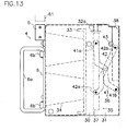
Figure 12 is a front elevation view of the stacker. -
Figure 13 is a side elevation view of the stacker. -
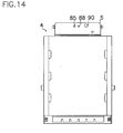
Figure 14 is a plan view of the stacker. -
Figure 15 is a flow chart showing a sequence for collecting bills from the stacker of the bill handling apparatus. - As shown in
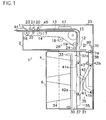
Figure 1 , a prior artbill handling apparatus 1 comprises avalidator 2 provided with aninlet 11 into which abill 44 is inserted, and astacker 4 defining astorage chamber 30 for accumulatingbills 44 considered genuine byvalidator 2.Validator 2 comprises aconvey device 26 for transportingbill 44 inserted frominlet 11 along a generally L-shaped passageway 13 extending frominlet 11 to anoutlet 12, and acontrol circuit 47 provided invalidator 2 for supplyingconvey device 26 with drive signals. Conveydevice 26 andcontrol circuit 47 provided invalidator 2 are disposed in a L-shaped frame 25 made of metallic panels. Conveydevice 26 comprises conveybelts 14 for transportingbill 44 alongpassageway 13, and drivepulleys 15 for driving conveybelts 14, and a plurality ofidle rollers 16 to 19 for supportingconvey belts 14. - Provided in the vicinity of
passageway 13 is adetection sensor 45 that comprises anoptical sensor 20 for detecting an optical feature ofbill 44 moving alongpassageway 13, and amagnetic sensor 21 for detecting a magnetic feature ofbill 44. Apinch roller 22 is positioned opposite to themagnetic sensor 21 to pushbill 44 towardmagnetic sensor 21.Inlet sensor 23 located atinlet 11 detects insertion ofbill 44 intoinlet 11. Anoutlet sensor 24 located atoutlet 12 detects discharge ofbill 44 fromvalidator 2. For example, each ofinlet sensor 23 andoutlet sensor 24 comprises photocoupler of light emitting diode and photo-transistor, andoptical sensor 20 comprises photocoupler of infrared ray emitting diode and photo-transistor. - Removably attached to a bottom of
validator 2 is portable ormobile stacker 4 that, as illustrated inFigure 1 , comprises acash box 6 formed with astorage chamber 30 and ahousing 31.Storage chamber 30 receives aback plate 33 and acompression spring 34 for resiliently urgingback plate 33 towardhousing 31. Apusher 35 is mounted inhousing 31 to press suppliedbill 44 intocash box 6. Pusher 35 comprises apush plate 37 for pressingbill 44 intostorage chamber 30, alink mechanism 36 connected topush plate 37 at the one end for drivingpush plate 37, and arack 38 connected to the other end oflink mechanism 36.Link mechanism 36 comprises a pair oflinks Link 41 has oneend 41a rotatably connected topush plate 37 and the other end 41b rotatably connected tocash box 6.Link 42 has oneend 42a rotatably connected topush plate 37 and theother end 42b rotatably connected torack 38 that is meshed with apinion 43 driven by aconvey motor 50 provided invalidator 2. - Connected to output shaft of convey
motor 50 is arotary encoder 51 that produces pulse signals in response to rotation of conveymotor 50 to count the pulse signals fromrotary encoder 51 by any pulse detector (not shown) in order to determine the moved position ofbill 44 alongpassageway 13.Output gear 50a mounted on output shaft of conveymotor 50 is drivingly connected to afirst gear 52 mounted on afirst shaft 53 through areduction device 60. Asecond gear 54 mounted onfirst shaft 53 is engaged with athird gear 55 protruded fromvalidator 2.Third gear 55 is drivingly connected to asixth gear 58 through fourth andfifth gears sixth gear 58 has apinion shaft 59 on whichpinion 43 is mounted. - Accordingly, when convey
motor 50 is rotated in one direction,rack 38 is upwardly moved as shown inFigure 4 to the upward position, whilepush plate 37 is moved away from achannel 32a to allowbill 44 to be moved betweenpush plate 37 andback plate 33 fromchannel 32a incash box 6. In this condition, when conveymotor 50 is rotated in the other direction,rack 38 is downwardly moved, whilepush plate 37 is moved towardback plate 33 throughlink mechanism 36, and therefore,push plate 37 can pressbill 44 supplied throughchannel 32a intocash box 6. - As shown in
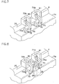
Figure 7 , anattachment lever 70 and astack lever 71 have a generally similar shape, and are rotatably mounted onshafts 72, 73 mounted onframe 25 between the original position shown inFigure 7 and operative position shown inFigure 9 .Attachment lever 70 has a round end 70a to which acam portion 74 ofstacker 4 may be brought into contact. Stacklever 71 has a round end 71a to which anend 38a ofrack 38 may be brought into contact. - As shown in
Figure 8 ,upper end 38a ofrack 38 extends through an opening 74a ofcam portion 74 to be brought into contact to round end 71a ofstack lever 71. Also,attachment lever 70 andstack lever 71 are resiliently urged toward their original positions respectively bysprings other end 70b ofattachment lever 70 is positioned within anattachment sensor 80 of light emitting diode and light receiving transistor. Also, in the original position, theother end 71b ofstack lever 71 is positioned withinstack sensor 81 of light emitting diode and light receiving transistor. Whenstacker 4 is not attached inframe 25,attachment lever 70 is in the original position shown inFigure 7 . Whenstacker 4 is attached inframe 25 as shown inFigure 5 ,cam portion 74 comes into contact to round end 70a ofattachment lever 70 to rotateattachment lever 70 in the clockwise direction from the original position ofFigure 7 to the operative position ofFigures 8 and9 against resilient force ofspring 75 and self-weight ofattachment lever 70 so thatattachment sensor 80 detects attachment ofstacker 4 tovalidator 2 because theother end 70b ofattachment lever 70 is removed fromattachment sensor 80. - Push
plate 37 is in the blocking position shown inFigure 1 whereinpush plate 37 coverschannel 32a ofcash box 6 to prevent unauthorized drawing ofbill 44 fromstacker 4. Whenrack 38 is moved to the downward position ofFigure 5 , pushplate 37presses bill 44 to the stacked position to release the engagement ofrack 38 withstack lever 71 that is then returned to the original position ofFigure 6 . Conversely, whenrack 38 is moved to the upward position, pushplate 37 is moved to the acceptant position ofFigure 4 to receivebill 44,rack 38 moves stacklever 71 to the operative position ofFigure 9 against resilient force ofspring 76 and own weight ofstack lever 71. In lieu ofattachment lever 70 and stacklever 71 rotatably mounted onframe 25, other means may be provided for example such as attachment rod and stack rod each slidable onframe 25. - As shown in
Figure 3 , in a prior artbill handling apparatus 1, aninlet sensor 23, anoptical sensor 20,attachment sensor 80 andstack sensor 81 are connected through anamplifier 48 to input terminals of acontrol circuit 47 whose output terminal is connected to amotor control circuit 46 for controlling a conveymotor 50. Upon insertion ofbill 44 intoinlet 11,detection sensor 45 detects physical feature, namely optical and magnetic patterns ofbill 44 routed to controlcircuit 47 that validatesbill 44 and decides denomination ofbill 44 in view of electric signals indicative of physical features ofbill 44. The read data is stored incontrol circuit 47 as bill information. - When
bill 44 is inserted intoinlet 11 ofvalidator 2,inlet sensor 23 detects insertion ofbill 44 to produce a detection signal to input terminal ofcontrol circuit 47 throughamplifier 48. At the moment,control circuit 47 forwards a drive signal tomotor control circuit 46 of conveydevice 26 to drive conveymotor 50 and drivepulley 15 in the forward direction so that conveybelts 14carries bill 44 inwardly alongpassageway 13. - Then, convey
motor 50 is rotated in one direction to upwardly moverack 38 as shown inFigure 4 and simultaneously movepush plate 37 from the blocking position to the acceptant position so thatbill 44 is carried in the standby position fromchannel 32a betweenback plate 33 and pushplate 37.Discharge sensor 24 detects arrival ofbill 44 at the standby position. Here, when conveymotor 50 is rotated in the reverse direction,rack 38 is downwardly moved andbill 44 is pressed intocash box 6 bypush plate 37 that is urged towardback plate 33 bylink mechanism 36.Stack lever 71 ofFigure 7 automatically detects movement ofpush plate 37 to certainly and forcibly putbill 44 intocash box 6 by operation ofpush plate 37 at the accurate timing. - Meanwhile, personnel must collect stackers housed in bill handling apparatuses such as parent gaming machine, for example, a slot machine, keeping sufficient security in cooperation of several people. In this case, while one of them takes
stacker 4 out of gaming machine, another should put the takenstacker 4 on a predetermined shelf of a container, and still another staff conveys the container in work allotment. If one of staffs carelessly puts thestacker 4 on a wrong shelf of container, no longer or hardly it is possible to confirm on which gaming machine thestacker 4 is removed from, and therefore, there is a defect that prompt check cannot be made regarding agreement between a total amount of collected bills fromstackers 4 and bill's amount recorded through gaming machines. -
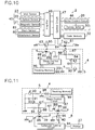
Figure 10 shows an electric circuit used in a new intelligent cash box system that is provided invalidator 2 andstacker 4 with anintelligent storage 5. In this system,control circuit 47 comprises acode memory 32 as a part thereof, and avalidator light emitter 61 and avalidator light receiver 63 each connected to controlcircuit 47.Validator light emitter 61 comprises atransistor 64 as a validator switching element, and a light emitting diode 62 as a validator light emitting element connected to one of main terminals, namely an emitter oftransistor 64. A control terminal, namely base oftransistor 64 is connected to controlcircuit 47, and the other of the main terminals, namely a collector is connected to a power sources not shown.Validator light emitter 63 comprises alight receiving transistor 65 connected to controlcircuit 47. -
Intelligent storage 5 mounted instacker 4 comprises a trackingmemory 99, astack light emitter 66, astack light receiver 67, astack control circuit 87 connected to trackingmemory 99, stacklight receiver 66 and stacklight emitter 67, and abattery 98 for supplying electric power to each circuit ofintelligent storage 5. In this embodiment, trackingmemory 99 has computing or calculating means for counting denomination or type and number ofbills 44 scanned bydetection sensor 45, butcontrol circuit 47 orcode memory 32 may have similar computing or calculating means for counting denomination or type and number ofbills 44 as required.Tracking memory 99 may be a part ofstack control circuit 87. - Stack
light emitter 66 comprises atransistor 86 as a stacker switching element, and alight emitting diode 85 as a stacker light emitting element connected to emitter, one of main terminals oftransistor 86. Control terminal or base oftransistor 86 is connected to stackcontrol circuit 87, and collector or the other of main terminals oftransistor 86 is grounded. Stacklight receiver 67 comprises alight receiving transistor 88 as a light receiving element, and aresistor 84 for grounding emitter oflight receiving transistor 88. Collector oflight receiving transistor 88 is connected to stackcontrol circuit 87. Connected in parallel relation toresistor 84 is a field effect transistor (FET) 91 as a gate element whose gate is connected to acapacitor 93 and alight receiving transistor 90 as a noise sensor, and emitter oflight receiving transistor 90. - When
stacker 4 in the separated condition ofFigure 6 is attached tovalidator 2 as shown inFigure 4 , light emitting diode 62 ofvalidator light emitter 61 is incorporated with light receivingtransistor 88 ofintelligent storage 5 without contact to each other to form a first photocoupler as shown inFigure 10 . Likewise,light receiving transistor 65 ofvalidator light receiver 63 is incorporated with light emittingdiode 85 ofintelligent storage 5 without contact to each other to form a second photocoupler.Light receiving transistor 65 receives light pulses indicative of information fromlight emitting diode 85 to confirm the status ofstack control circuit 87 bycontrol circuit 47 for example on whether previous information in trackingmemory 99 has been deleted or whether unnecessary information is stored in trackingmemory 99. - As shown in
Figure 11 , aninformation collector 8 comprises acollection light emitter 39, acollection light receiver 40, acollection control circuit 94 connected tocollection light emitter 39 andcollection light receiver 40 at each input terminal, and aprinter 27 connected to an output terminal ofcollection control circuit 94.Collection light emitter 39 comprises atransistor 97 with a control terminal or base connected tocollection control circuit 94, and alight emitting diode 96 connected to emitter oftransistor 97 whose collector is grounded.Collection light receiver 40 comprises alight receiving transistor 95 connected betweencollection control circuit 94 and earth or ground. Whenintelligent storage 5 is positioned in front ofinformation collector 8, as shown inFigure 11 ,light receiving transistor 95 ofcollection light receiver 40 is incorporated with light emittingdiode 85 ofintelligent storage 5 without contact to each other to form a third photocoupler for transmitting light pulses fromstack light emitter 66 tocollection light receiver 40. Similarly,light emitting diode 96 ofcollection light emitter 39 is mated with light receivingtransistor 88 ofintelligent storage 5 in the non-contact condition to form a fourth photocoupler for transmitting light pulses fromcollection light emitter 39 to stacklight receiver 67. For example,control circuit 47 confirms the status ofstack control circuit 87 whether trackingmemory 99 contains any information or unnecessary information or whether trackingmemory 99 can do its function well. - The method for transmitting code information is described hereinafter in connection with
Figure 15 . Initially, as shown inFigure 15(a) , a printer 7 is connected to a supervisingcomputer 28 to record a code on a card 3 by printer 7 and issue card 3 from printer 7 so that issued card 3 bears the recorded code for identifying a specific bill handling apparatus, and the code can be optically or magnetically read out bydetection sensor 45. For example, the code is recorded with bar codes, symbols, numerals or alphabets on card 3 or by perforating card 3 to form a punch card to denote a machine number for identifying a parent slot machine. Preferably, the recorded code includes invisible, indecipherable or incomprehensible letters, devices, symbols or alphabets. Otherwise, the code can be recorded on card 3 with ferrous ink to magnetically detect the code for example with a magnetic head. In this embodiment, assume an entertainment area equipped with a number of gaming machines that each has a bill handling apparatus with astacker 4 for accumulatingbills 44 to be collected. Each bill handling apparatus should store a code as a supervision number for identifying the gaming machine on which bill handling apparatus is mounted. To this end, supervisingcomputer 28 with printer 7 provides a card issue machine for dispensing cards 3 that bear recorded or printed different codes for identifying the gaming machines orvalidators 2. - Then, as shown in
Figure 15(b) , when issued card 3 is inserted intoinlet 11 ofvalidator 2,inlet sensor 23 detects insertion of card 3 to produce a detection signal to controlcircuit 47 that supplies drive signals tomotor control circuit 46. Accordingly, conveymotor 50 rotates in the forward direction to inwardly move card 3 alongpassageway 13 by driving conveybelts 14, whiledetection sensor 45 scans and converts the code on card 3 into electric signals to controlcircuit 47 to store the code incode memory 32. Then, controlcircuit 47 providesmotor control circuit 46 with reverse drive signals to rotate conveymotor 50 in the reverse direction so that card 3 is returned toinlet 11. - Next, as shown in
Figure 15(c) ,stacker 4 withintelligent storage 5 is attached in position withinframe 25 ofvalidator 2 so thatattachment lever 70 rotates from the original position ofFigure 7 to the operative position ofFigure 9 , andattachment sensor 80 detects installation ofstacker 4 to generate a detection signal to controlcircuit 47. - After
control circuit 47 receives the detection signal fromattachment sensor 80,control circuit 47 forwards pulse array signals indicative of code data stored incode memory 32 to base oftransistor 64 to intermittently drivetransistor 64 in the ON-OFF mode. In this case,control circuit 47 receives parallel signals of code information stored incode memory 32, and converts them into series pulse array signals indicated by binary code of "0" and "1" for base oftransistor 64. Operation oftransistor 64 in the ON-OFF mode causes light emitting diode 62 to blink in accordance with series pulse array signals, andlight receiving transistor 88 receives optical pulse signals from light emitting diode 62 and transmits them to stackcontrol circuit 87 that forwards the series signals to trackingmemory 99 for storage therein as code information. - After all code information is stored in
stack control circuit 87 or trackingmemory 99,stack control circuit 87 supplies drive signals to base oftransistor 86 to intermittently operatetransistor 86 in the ON-OFF mode and thereby causelight emitting diode 85 ofintelligent storage 5 to blink in the predetermined mode.Light receiving transistor 65 ofvalidator light receiver 63 receives light signals from light emittingdiode 85 and supplies them to controlcircuit 47 to confirm storage of code information instack control circuit 87 or trackingmemory 99. When light receivingtransistor 90 receives disturbing light before attachment ofstacker 4 to frame 25, electric current flows throughlight receiving transistor 90 to reduce gate voltage ofFET 91 that is then turned OFF so that pulse array signals are not routed to stackcontrol circuit 87 althoughlight receiving transistor 88 receives light signals from light emitting diode 62. Pulse array signals stored as code information instack control circuit 87 or trackingmemory 99 cannot be decoded unless they are read out through a specific decoding software. - After that, in use of gaming machine, users throw each
bill 44 intoinlet 11 anddetection sensor 45 detects physical feature ofbill 44 moving alongpassageway 13 and forwards it to controlcircuit 47 that validates authenticity ofbill 44. Whencontrol circuit 47 decidesbill 44 as genuine,bill 44 is accumulated instacker 4.Control circuit 47 transmits electric signals indicative of denomination or type and value ofgenuine bill 44 as bill information to trackingmemory 99 throughstacker control circuit 47 for storage of bill information in trackingmemory 99, eachtime bill 44 is stacked instacker 4, while computing means in trackingmemory 99 calculates total number or total of each denomination of storedbills 44. In this case, similarly to code information,control circuit 47 converts parallel signals of bill information into series pulse array signals indicated by binary code of "0" and "1", and sends them to base oftransistor 64. Operation oftransistor 64 in the ON-OFF mode causes light emitting diode 62 to blink in accordance with the series pulse array signals, andlight receiving transistor 88 receives light signals form light emitting diode 62 and transmits them to stackcontrol circuit 87 and trackingmemory 99 for storage therein as bill information. - After all bill information is stored in
stack control circuit 87 or trackingmemory 99,stack control circuit 87 again supplies drive signals to base oftransistor 86 to intermittently operatetransistor 86 in the ON-OFF mode and thereby causelight emitting diode 85 ofintelligent storage 5 to blink in the predetermined mode so that light receivingtransistor 65 ofvalidator light receiver 63 receives light signals from light emittingdiode 85 and supplies them to controlcircuit 47 to confirm storage of bill information instack control circuit 87 or trackingmemory 99. Alternatively,control circuit 47 may transmit code information and bill information to stackcontrol circuit 87 or trackingmemory 99 for storage of these information therein eachtime bill 44 is stacked instacker 4, not whencontrol circuit 47 receives detection signal fromattachment sensor 80. - In collecting
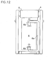
bills 44 preserved instacker 4, an operator opens a door (not shown) of gaming machine, grips and pulls ahandle 6a provided on a front surface ofintelligent cash box 6 shown inFigures 12 and13 to removecash box 6 fromstacker 4, and take outbills 44 fromcash box 6.Handle 6a is rotatably mounted aroundbrackets 6b oncash box 6. Subsequently, as shown inFigure 15(e) ,stacker 4 is turned upside down and put oninformation collector 8 in position to, as shown inFigure 11 , form the third photocoupler by combination of light receivingtransistor 95 ofcollector light receiver 40 andlight emitting diode 85 ofintelligent storage 5 and the fourth photocoupler by combination oflight emitting diode 96 ofcollector light emitter 39 andlight receiving transistor 88 ofintelligent storage 5. Here, whencollection control circuit 94 forwards drive signals to base oftransistor 97 to causelight emitting diode 96 to flash in the specific ON-OFF mode of coded signals. - Under the condition,
light receiving transistor 88 receives light signals from light emittingdiode 96 to supply the coded signals to stackcontrol circuit 87 that thereby provides base oftransistor 86 with drive signals to drivetransistor 86 in the ON-OFF mode to transmit code information and bill information stored in trackingmemory 99 tocollection control circuit 94. In response to operation oftransistor 86,light emitting diode 86 flashes to generate light signals that are received bylight receiving transistor 95. Thus,collection control circuit 94 providesprinter 27 with code information for identifying the gaming machine and bill information for indicating denomination or type and value of bills to record these information on sheet 9 byprinter 27. - As shown in
Figure 15 (f) , data printed on sheet 9 is then optically read by ascanner 10, and forwarded fromscanner 10 to aconfirmative computer 29. In this case, when bill information indicated on display ofconfirmative computer 29 corresponds to the number and denomination or type ofbills 44 collected fromcash box 6 as mentioned above, the data is stored inconfirmative computer 29 for supervision. Then, data stored in trackingmemory 99 ofstacker 4 is deleted wheninformation collector 8 finishes reading out data from trackingmemory 99, when a reset switch (not shown) in stacker is operated or when light receivingtransistor 88 receives light signals from light emitting diode 62 afterstacker 4 is attached to frame 25 for reuse ofstacker 4, or in one of other cases. Without printing the information byprinter 27,information collector 8 may directly be connected toconfirmative computer 29 via conducting wires to directly supply the information toconfirmative computer 29 for input or printing. - Embodiments according to the present invention can produce the following advantages utilizing card 3 bearing code information:
- [1] Code information received by
information collector 8 serves to promptly and exactly identify thebill handling apparatus 1 from which stacker 4 is removed. - [2]
Bill handling apparatus 1 may have the simplified structure of electric circuits because there is no need for connectingcontrol circuit 47 on line with supervising computer becausevalidator 2 detects code information indicated on card 3 for identifying bill handling apparatus and store the information. - [3]
Bill handling apparatus 1 orvalidator 2 does not require any additional hardware to receive code information because acommon detection sensor 45 can be used to discern bill's physical property and code recorded on card 3 and to store the code instacker 4. - [4] Prompt and accurate check can be made between collected bills and bill information stored in
stacker 4. - [5] Code information for identifying
bill handling apparatus 1 can easily be changed by inserting a card 3 of a different code intovalidator 2 for storage of the code information. - [6] A code different from manufacture number of parent machine or bill handling apparatus can be recorded on card 3.
- Moreover, embodiments of the present invention can present the following advantages utilizing photocouplers:
- [1] There is no need of electric connection with jacks and plugs between
validator 2 andstacker 4 and betweenstacker 4 andinformation collector 8, andstacker 4 can easily be attached tovalidator 2 andinformation collector 8. - [2] Non-contact transmission of bill information and code information can be made between
validator 2 andstacker 4 and betweenstacker 4 andinformation collector 8 avoiding mechanical contact failure and damage from external electric impact. - [3] Two way communication by a pair of photocouplers between
validator 2 andstacker 4 and betweenstacker 4 andinformation collector 8 enables confirmation of failure of a mated device. - [4]
Stacker 4 can be moved and attached tovalidator 2 together withintelligent storage 5. - [5]
Stacker 4 can be compatible for reuse by erasing information in trackingmemory 99. - [6]
Tracking memory 99 always stores data of current or updated amount of bills instacker 4 because bill information is stored in real time in trackingmemory 99 eachtime bill 44 is pressed intostacker 4. - [7] No information can be read out from tracking
memory 99 without photocouplers conforming tostacker 4 and exclusive software applied toinformation collector 8 for decoding pulse array signals fromstacker 4, for improved security and prevention of unauthorized information retrieval. - [8]
Tracking memory 99 has the function for storing, adding and computing bill information. - The foregoing embodiment shows an example of the present invention applied to a bill handling apparatus of gaming machine such as slot machine, however, it should be understood that the present invention also can be applied to cash dispensers, vending machines, exchangers or other bill handling machines installed in banks, amusement facilities or other transaction areas. Also, in lieu of bills, coupons, scrip, tokens may be used.
Claims (10)
- A bill handling apparatus comprising:validating means (2) for attesting a bill (44) inserted into the inlet (11) of said validating means, stacking means (4) detachably mounted on said validating means for accumulating the bills authenticated by said validating means, and an intelligent cash box system adapted to transmit information from said validating means to said stacking means;said intelligent cash box system comprising: a card (3) bearing at least a code recorded on said card identifying said bill handling apparatus, said card being capable of being inserted into the inlet of said validating means adapted to detect the code by sensing means (45) and store the code in control means (47) as code information in said validating means, and an intelligent storage (5) provided in said stacking means in communication with the control means of said validating means and adapted to receive the code He information and bill information from said control means and store this information in said intelligent storage,said bill information including data of the bills received in a storage chamber (30) of said stacking means and being transmitted from said control means to said intelligent storage.
- The bill handling apparatus of claim 1, wherein said validating means (2) comprises conveying means (26) for transporting the bill inserted into the inlet (11) along a passageway (13), said sensing means (45) for detecting a physical feature of the transported bill to produce electric signals indicative of the bill's physical feature, and said control means (47) for attesting the bill based on output signals of said sensing means and also forwarding drive signals to said conveying means;
said stacking means (4) comprises said storage chamber (30) for receiving the bills considered genuine by the control means and transmitted by the conveying means through the passageway. - The bill handling apparatus of claim 2, further comprising information collecting means (8) provided independently from said validating means (2) for receiving said code information and bill information from the intelligent storage (5) of said stacking means (4) removed from said validating means.
- The bill handling apparatus of claim 2, further comprising a card issue machine (7) for recording the code on said card (3) and issuing said card.
- The bill handling apparatus of claim 2, wherein at least one of said control means (47) and intelligent storage (5) comprises computing means for calculating the number and kind or denomination of the bills detected by said sensing means.
- The bill handling apparatus of claim 4, wherein said card issue machine (7) prints or records on said card (3) the code selected from bar codes, symbols, numerals or alphabets or perforates said card to form a punch card.
- The bill handling apparatus of claim 2, wherein said intelligent cash box system further comprises photocoupler (62, 88 and 65, 85) means provided between said control means (47) and intelligent storage (5) for transmitting the code information and bill information in the non-contact condition of said control means and intelligent storage through said photocoupler means.
- The bill handling apparatus of claim 3, wherein said intelligent cash box system further comprises photocoupler (95, 85 and 96, 88) means provided between said intelligent storage (5) and a collection control circuit (94) for transmitting the code information and bill information in the non-contact condition of said intelligent storage and collection control circuit through said photocoupler means.
- The bill handling apparatus of claim 2, wherein said control means (47) comprises a code memory (32) for storing the code information, and said intelligent storage (5) comprises a tracking memory (99) for storing code information and bill information.
- The bill handling apparatus of claim 2, wherein said validating means (2) comprises a validator light emitter (62) connected to said control means (47), said intelligent storage (5) comprises a stack control circuit (87) and a stack light receiver (88) connected to said stack control circuit,
said stack light receiver (88) is located opposite to and in spaced relation to said validator light emitter (62) to provide a first photocoupler of said validator light emitter and stack light receiver after said stacking means is attached to said validating means,
said stack control circuit receives light signals indicative of the code information and bill information from said control means through said first photocoupler and stores these signals.
Applications Claiming Priority (3)
| Application Number | Priority Date | Filing Date | Title |
|---|---|---|---|
| JP2002322463A JP3909841B2 (en) | 2002-11-06 | 2002-11-06 | Bill handling apparatus and bill information transmission method |
| JP2002322463 | 2002-11-06 | ||
| PCT/JP2003/014142 WO2004042665A1 (en) | 2002-11-06 | 2003-11-06 | Billhandling apparatus and method for transmitting code information |
Publications (3)
| Publication Number | Publication Date |
|---|---|
| EP1559078A1 EP1559078A1 (en) | 2005-08-03 |
| EP1559078A4 EP1559078A4 (en) | 2007-07-11 |
| EP1559078B1 true EP1559078B1 (en) | 2012-12-26 |
Family
ID=32310390
Family Applications (1)
| Application Number | Title | Priority Date | Filing Date |
|---|---|---|---|
| EP03810623A Expired - Lifetime EP1559078B1 (en) | 2002-11-06 | 2003-11-06 | Billhandling apparatus and method for transmitting code information |
Country Status (11)
| Country | Link |
|---|---|
| US (2) | US7909152B2 (en) |
| EP (1) | EP1559078B1 (en) |
| JP (1) | JP3909841B2 (en) |
| KR (1) | KR100985623B1 (en) |
| CN (1) | CN100410973C (en) |
| AU (1) | AU2003276714B2 (en) |
| CA (1) | CA2504996C (en) |
| ES (1) | ES2401984T3 (en) |
| RU (1) | RU2304310C2 (en) |
| WO (1) | WO2004042665A1 (en) |
| ZA (1) | ZA200504039B (en) |
Families Citing this family (27)
| Publication number | Priority date | Publication date | Assignee | Title |
|---|---|---|---|---|
| JP4454023B2 (en) * | 2005-02-17 | 2010-04-21 | 株式会社ユニバーサルエンターテインメント | Banknote handling equipment |
| CH704737B1 (en) | 2005-05-27 | 2012-10-15 | Peter Villiger | A safety case, safety and containment system. |
| WO2007016091A2 (en) * | 2005-07-27 | 2007-02-08 | Mei, Inc. | Cassette for storing bills and the like |
| JP4901227B2 (en) * | 2006-01-27 | 2012-03-21 | 株式会社東芝 | Paper sheet processing system |
| ITMI20060407A1 (en) * | 2006-03-07 | 2007-09-08 | Razzaboni Cima Spa | DEVICE AND METHOD FOR STORAGE AND DISTRIBUTION OF BANKNOTES |
| US8851373B2 (en) * | 2006-06-14 | 2014-10-07 | Mei, Inc. | Tracking information in a note handling facility |
| CA2703127A1 (en) * | 2006-10-20 | 2008-05-02 | Coin Acceptors, Inc. | A method of receiving and paying out bills |
| TWI301598B (en) * | 2006-10-24 | 2008-10-01 | Int Currency Tech | Calibration system and method thereof |
| JP5269506B2 (en) * | 2007-10-24 | 2013-08-21 | 株式会社ユニバーサルエンターテインメント | Banknote handling equipment |
| JP5188167B2 (en) * | 2007-12-20 | 2013-04-24 | 株式会社ユニバーサルエンターテインメント | Paper sheet processing equipment |
| US20090223776A1 (en) * | 2008-03-05 | 2009-09-10 | International Currency Technologies Corporation | Bill acceptor with licence/bill recognition |
| US20090242353A1 (en) * | 2008-03-31 | 2009-10-01 | International Currency Technologies Corporation | Bill accetor |
| US20100320056A1 (en) * | 2008-03-31 | 2010-12-23 | International Currency Technologies Corporation | Bill acceptor that prevents arching of each received bill |
| US8267238B2 (en) * | 2009-03-16 | 2012-09-18 | Glory Ltd. | Banknote depositing machine and banknote depositing method |
| US10621823B2 (en) * | 2009-11-16 | 2020-04-14 | Global Payment Technologies Australia Pty Ltd | Systems and methods for providing interaction with a terminal |
| CN102542654B (en) * | 2010-12-17 | 2014-04-09 | 辽宁聚龙金融设备股份有限公司 | Installation structure of magnetism detection sensor of paper money sorter and paper money counting machine |
| EP2505530A3 (en) * | 2011-03-31 | 2013-05-22 | Glory Ltd. | Money handling system and money handling method |
| JP5971147B2 (en) * | 2013-02-14 | 2016-08-17 | 沖電気工業株式会社 | Media processing device |
| JP6121300B2 (en) * | 2013-09-26 | 2017-04-26 | 日本電産サンキョー株式会社 | Card reader |
| JP6409502B2 (en) * | 2014-03-31 | 2018-10-24 | 沖電気工業株式会社 | Medium processing apparatus and medium transaction apparatus |
| JP2016057968A (en) * | 2014-09-11 | 2016-04-21 | 沖電気工業株式会社 | Medium transaction device |
| CN107148641B (en) * | 2014-10-03 | 2021-05-25 | 三菱电机株式会社 | Image reading apparatus |
| CN104331980A (en) * | 2014-11-04 | 2015-02-04 | 广州御银自动柜员机技术有限公司 | Voucher scanning and recovering device and recovering method thereof |
| KR102312906B1 (en) * | 2017-03-31 | 2021-10-15 | 효성티앤에스 주식회사 | Portable cassette holder |
| JP6811140B2 (en) * | 2017-04-12 | 2021-01-13 | 日本金銭機械株式会社 | Paper leaf discrimination device and paper leaf discrimination system |
| CN107067067A (en) * | 2017-04-14 | 2017-08-18 | 永道无线射频标签(扬州)有限公司 | The workflow of individual ticket card different pattern identification sorting |
| US20200372584A1 (en) * | 2019-05-23 | 2020-11-26 | Jcm American Corporation | Currency Tracking and Accounting Systems |
Family Cites Families (24)
| Publication number | Priority date | Publication date | Assignee | Title |
|---|---|---|---|---|
| GB2165383B (en) * | 1984-10-03 | 1988-05-25 | Ncr Co | Data sensing system for currency cassettes |
| JPS61253696A (en) * | 1985-05-02 | 1986-11-11 | Hitachi Ltd | Semiconductor integrated circuit device and its manufacture |
| JPS61253596A (en) | 1985-05-07 | 1986-11-11 | 株式会社日立製作所 | Cash teller's equipment |
| FR2584516B1 (en) * | 1985-07-02 | 1988-05-13 | Smh Alcatel | MONITORING METHOD AND SYSTEM FOR POSTAGE MACHINES |
| SE455653B (en) * | 1987-08-11 | 1988-07-25 | Inter Innovation Ab | PLANT FOR SECURE TRANSMISSION OF ATMINSTONE VALUE OF SECURITIES FROM A MULTIPLE EXTENSION OF DISTRIBUTED TEMINALS TO A CENTRALLY LOCATED MONEY DEVICE |
| GB8908528D0 (en) * | 1989-04-14 | 1989-06-01 | Ncr Co | Data transfer system for currency cassettes |
| JP3253335B2 (en) * | 1992-01-20 | 2002-02-04 | 株式会社東芝 | Cash management system |
| GB2273840A (en) * | 1992-12-09 | 1994-06-29 | Sony Corp | Optically transmitting signals between measurement devices |
| JP2973385B2 (en) * | 1992-12-30 | 1999-11-08 | 株式会社日本コンラックス | Coin sorting equipment such as vending machines |
| US5655961A (en) * | 1994-10-12 | 1997-08-12 | Acres Gaming, Inc. | Method for operating networked gaming devices |
| US5491326A (en) * | 1994-11-23 | 1996-02-13 | Xcp, Inc. | Card metering system |
| US5630755A (en) * | 1995-04-07 | 1997-05-20 | Coin Bill Validator, Inc. | Soft count tracking system |
| US5743429A (en) * | 1995-09-26 | 1998-04-28 | Debit Dial Vending Corp. | Device for dispensing credit cards |
| US5662202A (en) * | 1995-11-24 | 1997-09-02 | Ardac Incorporated | Currency validator with cassette cash box |
| US5907141A (en) * | 1996-07-19 | 1999-05-25 | Mars Incorporated | Use of security coupons in connection with locking mechanisms for vending and gaming machines |
| JPH10261131A (en) | 1997-03-21 | 1998-09-29 | Toshiba Corp | Intelligent safe and cash processing system using the same |
| US6845905B2 (en) * | 1997-03-26 | 2005-01-25 | Vendingdata Corporation | Currency container tracking system and a currency container for use therewith |
| US6065672A (en) * | 1997-07-24 | 2000-05-23 | Currency Systems International | Method for currency distribution and management |
| US6109522A (en) * | 1997-11-28 | 2000-08-29 | Diebold, Incorporated | Automated banking machine with self auditing capabilities and system |
| US6059090A (en) * | 1998-04-13 | 2000-05-09 | Agent Systems, Inc. | Configurable cashbox |
| US6749053B2 (en) * | 2000-02-22 | 2004-06-15 | Glory Kogyo Kabushiki Kaisha | Bill handling machine |
| CN1145118C (en) * | 2001-01-15 | 2004-04-07 | 福士电机株式会社 | Control device of automatic vendor |
| US6896116B2 (en) * | 2002-06-18 | 2005-05-24 | Mars Incorporated | Bill acceptor |
| US6738690B2 (en) * | 2002-08-08 | 2004-05-18 | Pj Solutions, Inc. | Information management of supply flow of dispensed objects |
-
2002
- 2002-11-06 JP JP2002322463A patent/JP3909841B2/en not_active Expired - Fee Related
-
2003
- 2003-11-05 US US10/702,533 patent/US7909152B2/en active Active
- 2003-11-06 RU RU2005117156/09A patent/RU2304310C2/en active
- 2003-11-06 WO PCT/JP2003/014142 patent/WO2004042665A1/en active Application Filing
- 2003-11-06 CA CA2504996A patent/CA2504996C/en not_active Expired - Lifetime
- 2003-11-06 AU AU2003276714A patent/AU2003276714B2/en not_active Expired
- 2003-11-06 KR KR1020057008124A patent/KR100985623B1/en active IP Right Grant
- 2003-11-06 ES ES03810623T patent/ES2401984T3/en not_active Expired - Lifetime
- 2003-11-06 EP EP03810623A patent/EP1559078B1/en not_active Expired - Lifetime
- 2003-11-06 CN CNB200380107188XA patent/CN100410973C/en not_active Expired - Lifetime
-
2005
- 2005-05-19 ZA ZA200504039A patent/ZA200504039B/en unknown
-
2006
- 2006-03-13 US US11/375,165 patent/US7913831B2/en active Active
Also Published As
| Publication number | Publication date |
|---|---|
| JP2004157740A (en) | 2004-06-03 |
| AU2003276714B2 (en) | 2008-05-29 |
| US20040149817A1 (en) | 2004-08-05 |
| CN1729489A (en) | 2006-02-01 |
| KR100985623B1 (en) | 2010-10-07 |
| KR20050070121A (en) | 2005-07-05 |
| US7913831B2 (en) | 2011-03-29 |
| WO2004042665A1 (en) | 2004-05-21 |
| RU2304310C2 (en) | 2007-08-10 |
| ZA200504039B (en) | 2006-04-26 |
| US7909152B2 (en) | 2011-03-22 |
| AU2003276714A1 (en) | 2004-06-07 |
| US20060151281A1 (en) | 2006-07-13 |
| ES2401984T3 (en) | 2013-04-26 |
| JP3909841B2 (en) | 2007-04-25 |
| CA2504996C (en) | 2012-07-17 |
| EP1559078A1 (en) | 2005-08-03 |
| EP1559078A4 (en) | 2007-07-11 |
| CN100410973C (en) | 2008-08-13 |
| RU2005117156A (en) | 2006-01-20 |
| CA2504996A1 (en) | 2004-05-21 |
Similar Documents
| Publication | Publication Date | Title |
|---|---|---|
| US7913831B2 (en) | Intelligent cash box system and method for transmitting code information | |
| RU2113728C1 (en) | Device for detection of sign information which is printed on documents | |
| US6845905B2 (en) | Currency container tracking system and a currency container for use therewith | |
| US6910625B2 (en) | Commercial self-service equipment | |
| WO2005029240A2 (en) | System and method for processing currency and identification cards in a document processing device | |
| JPS584496A (en) | Dual-purpose type automation unit for providing and storing securities such as bank note, check, receipt and coupon | |
| WO1992017856A1 (en) | Remote credit card issuance apparatus and method | |
| EP2012279A2 (en) | Bills and/or card validator and storage apparatus | |
| US6993758B1 (en) | Method and apparatus for renewing software in a software-operated machine | |
| CN106934923B (en) | Exchange machine and exchange method | |
| MX2014000236A (en) | Document handler for table games. | |
| CA2753931C (en) | Valuable paper treating system | |
| JP2000322632A (en) | Handling device for coins or the like | |
| KR200374272Y1 (en) | Device for drawing bills from auto teller machine | |
| KR20080053032A (en) | Method of magnetic ink character recognition automatic teller machine for checks | |
| JP2696089B2 (en) | Automatic transaction equipment | |
| JP2742538B2 (en) | Automatic transaction device and safe cassette incorporated in the device | |
| JPH10172066A (en) | Paper money loading system | |
| KR920004421B1 (en) | Automatic transaction system | |
| JPH06215235A (en) | Automatic paper money transaction machine | |
| JPS6382544A (en) | Consumer transaction facility | |
| KR20060042594A (en) | Device for drawing bills from auto teller machine | |
| ZA200106515B (en) | Method and apparatus for renewing software in a software-operated machine. | |
| JPS59229376A (en) | Bankbook handling apparatus |
Legal Events
| Date | Code | Title | Description |
|---|---|---|---|
| PUAI | Public reference made under article 153(3) epc to a published international application that has entered the european phase |
Free format text: ORIGINAL CODE: 0009012 |
|
| 17P | Request for examination filed |
Effective date: 20050504 |
|
| AK | Designated contracting states |
Kind code of ref document: A1 Designated state(s): AT BE BG CH CY CZ DE DK EE ES FI FR GB GR HU IE IT LI LU MC NL PT RO SE SI SK TR |
|
| AX | Request for extension of the european patent |
Extension state: AL LT LV MK |
|
| DAX | Request for extension of the european patent (deleted) | ||
| RBV | Designated contracting states (corrected) |
Designated state(s): AT DE ES GB IT |
|
| A4 | Supplementary search report drawn up and despatched |
Effective date: 20070612 |
|
| RIC1 | Information provided on ipc code assigned before grant |
Ipc: G07D 11/00 20060101AFI20070606BHEP |
|
| 17Q | First examination report despatched |
Effective date: 20080128 |
|
| GRAP | Despatch of communication of intention to grant a patent |
Free format text: ORIGINAL CODE: EPIDOSNIGR1 |
|
| GRAS | Grant fee paid |
Free format text: ORIGINAL CODE: EPIDOSNIGR3 |
|
| GRAA | (expected) grant |
Free format text: ORIGINAL CODE: 0009210 |
|
| AK | Designated contracting states |
Kind code of ref document: B1 Designated state(s): AT DE ES GB IT |
|
| REG | Reference to a national code |
Ref country code: GB Ref legal event code: FG4D |
|
| REG | Reference to a national code |
Ref country code: AT Ref legal event code: REF Ref document number: 590816 Country of ref document: AT Kind code of ref document: T Effective date: 20130115 |
|
| REG | Reference to a national code |
Ref country code: DE Ref legal event code: R096 Ref document number: 60342978 Country of ref document: DE Effective date: 20130228 |
|
| PLBE | No opposition filed within time limit |
Free format text: ORIGINAL CODE: 0009261 |
|
| STAA | Information on the status of an ep patent application or granted ep patent |
Free format text: STATUS: NO OPPOSITION FILED WITHIN TIME LIMIT |
|
| 26N | No opposition filed |
Effective date: 20130927 |
|
| REG | Reference to a national code |
Ref country code: DE Ref legal event code: R097 Ref document number: 60342978 Country of ref document: DE Effective date: 20130927 |
|
| PGFP | Annual fee paid to national office [announced via postgrant information from national office to epo] |
Ref country code: IT Payment date: 20221124 Year of fee payment: 20 Ref country code: GB Payment date: 20221125 Year of fee payment: 20 Ref country code: DE Payment date: 20221123 Year of fee payment: 20 Ref country code: AT Payment date: 20221121 Year of fee payment: 20 |
|
| PGFP | Annual fee paid to national office [announced via postgrant information from national office to epo] |
Ref country code: ES Payment date: 20230125 Year of fee payment: 20 |
|
| P01 | Opt-out of the competence of the unified patent court (upc) registered |
Effective date: 20230524 |
|
| REG | Reference to a national code |
Ref country code: DE Ref legal event code: R071 Ref document number: 60342978 Country of ref document: DE |
|
| REG | Reference to a national code |
Ref country code: GB Ref legal event code: PE20 Expiry date: 20231105 |
|
| REG | Reference to a national code |
Ref country code: ES Ref legal event code: FD2A Effective date: 20231201 |
|
| REG | Reference to a national code |
Ref country code: AT Ref legal event code: MK07 Ref document number: 590816 Country of ref document: AT Kind code of ref document: T Effective date: 20231106 |
|
| PG25 | Lapsed in a contracting state [announced via postgrant information from national office to epo] |
Ref country code: GB Free format text: LAPSE BECAUSE OF EXPIRATION OF PROTECTION Effective date: 20231105 |
|
| PG25 | Lapsed in a contracting state [announced via postgrant information from national office to epo] |
Ref country code: ES Free format text: LAPSE BECAUSE OF EXPIRATION OF PROTECTION Effective date: 20231107 |
|
| PG25 | Lapsed in a contracting state [announced via postgrant information from national office to epo] |
Ref country code: GB Free format text: LAPSE BECAUSE OF EXPIRATION OF PROTECTION Effective date: 20231105 Ref country code: ES Free format text: LAPSE BECAUSE OF EXPIRATION OF PROTECTION Effective date: 20231107 |