EP1560010B1 - Load cell with strain gauge with adhesive layer of inorganic-organic hybrid-polymer (ORMOCER) - Google Patents
Load cell with strain gauge with adhesive layer of inorganic-organic hybrid-polymer (ORMOCER) Download PDFInfo
- Publication number
- EP1560010B1 EP1560010B1 EP04075198A EP04075198A EP1560010B1 EP 1560010 B1 EP1560010 B1 EP 1560010B1 EP 04075198 A EP04075198 A EP 04075198A EP 04075198 A EP04075198 A EP 04075198A EP 1560010 B1 EP1560010 B1 EP 1560010B1
- Authority
- EP
- European Patent Office
- Prior art keywords
- strain gauge
- layer
- deformable body
- inorganic
- adhesive layer
- Prior art date
- Legal status (The legal status is an assumption and is not a legal conclusion. Google has not performed a legal analysis and makes no representation as to the accuracy of the status listed.)
- Expired - Lifetime
Links
- 229920000642 polymer Polymers 0.000 title claims abstract description 52
- 239000012790 adhesive layer Substances 0.000 title claims abstract description 39
- 239000010410 layer Substances 0.000 claims abstract description 79
- 238000000034 method Methods 0.000 claims abstract description 23
- 229910052782 aluminium Inorganic materials 0.000 claims abstract description 10
- XAGFODPZIPBFFR-UHFFFAOYSA-N aluminium Chemical compound [Al] XAGFODPZIPBFFR-UHFFFAOYSA-N 0.000 claims abstract description 10
- 239000000758 substrate Substances 0.000 claims abstract description 7
- 230000004888 barrier function Effects 0.000 claims description 17
- 230000001070 adhesive effect Effects 0.000 claims description 15
- 239000000853 adhesive Substances 0.000 claims description 14
- TWNQGVIAIRXVLR-UHFFFAOYSA-N oxo(oxoalumanyloxy)alumane Chemical compound O=[Al]O[Al]=O TWNQGVIAIRXVLR-UHFFFAOYSA-N 0.000 claims description 12
- 229910010272 inorganic material Inorganic materials 0.000 claims description 11
- 239000011147 inorganic material Substances 0.000 claims description 11
- 239000011253 protective coating Substances 0.000 claims description 9
- 229910052581 Si3N4 Inorganic materials 0.000 claims description 5
- HQVNEWCFYHHQES-UHFFFAOYSA-N silicon nitride Chemical compound N12[Si]34N5[Si]62N3[Si]51N64 HQVNEWCFYHHQES-UHFFFAOYSA-N 0.000 claims description 5
- VYPSYNLAJGMNEJ-UHFFFAOYSA-N Silicium dioxide Chemical compound O=[Si]=O VYPSYNLAJGMNEJ-UHFFFAOYSA-N 0.000 claims description 4
- QVGXLLKOCUKJST-UHFFFAOYSA-N atomic oxygen Chemical compound [O] QVGXLLKOCUKJST-UHFFFAOYSA-N 0.000 claims description 4
- 239000011248 coating agent Substances 0.000 claims description 4
- 238000000576 coating method Methods 0.000 claims description 4
- 239000001301 oxygen Substances 0.000 claims description 4
- 229910052760 oxygen Inorganic materials 0.000 claims description 4
- 230000035515 penetration Effects 0.000 claims description 4
- 229910052814 silicon oxide Inorganic materials 0.000 claims description 4
- 239000000126 substance Substances 0.000 claims description 4
- 238000004873 anchoring Methods 0.000 claims description 3
- 239000012298 atmosphere Substances 0.000 claims description 3
- 238000007639 printing Methods 0.000 claims description 2
- 150000001875 compounds Chemical class 0.000 claims 5
- 238000009499 grossing Methods 0.000 claims 2
- 230000001681 protective effect Effects 0.000 claims 2
- 238000007669 thermal treatment Methods 0.000 claims 1
- 239000000463 material Substances 0.000 description 20
- 239000011241 protective layer Substances 0.000 description 10
- 238000005452 bending Methods 0.000 description 9
- 230000008569 process Effects 0.000 description 7
- 229920001721 polyimide Polymers 0.000 description 6
- 239000004642 Polyimide Substances 0.000 description 5
- 238000007649 pad printing Methods 0.000 description 5
- 238000005303 weighing Methods 0.000 description 5
- 239000004593 Epoxy Substances 0.000 description 4
- 230000009471 action Effects 0.000 description 4
- 230000000694 effects Effects 0.000 description 4
- 238000005516 engineering process Methods 0.000 description 4
- 125000003700 epoxy group Chemical group 0.000 description 4
- 239000000945 filler Substances 0.000 description 4
- 229910052751 metal Inorganic materials 0.000 description 4
- 239000002184 metal Substances 0.000 description 4
- 230000001680 brushing effect Effects 0.000 description 3
- 230000008859 change Effects 0.000 description 3
- 239000002131 composite material Substances 0.000 description 3
- 238000004132 cross linking Methods 0.000 description 3
- 238000010438 heat treatment Methods 0.000 description 3
- 239000002245 particle Substances 0.000 description 3
- 230000000704 physical effect Effects 0.000 description 3
- 229920000647 polyepoxide Polymers 0.000 description 3
- 229920000877 Melamine resin Polymers 0.000 description 2
- CERQOIWHTDAKMF-UHFFFAOYSA-M Methacrylate Chemical compound CC(=C)C([O-])=O CERQOIWHTDAKMF-UHFFFAOYSA-M 0.000 description 2
- PNEYBMLMFCGWSK-UHFFFAOYSA-N aluminium oxide Inorganic materials [O-2].[O-2].[O-2].[Al+3].[Al+3] PNEYBMLMFCGWSK-UHFFFAOYSA-N 0.000 description 2
- 230000008901 benefit Effects 0.000 description 2
- 239000000969 carrier Substances 0.000 description 2
- 239000012876 carrier material Substances 0.000 description 2
- 239000000919 ceramic Substances 0.000 description 2
- 238000009833 condensation Methods 0.000 description 2
- 230000005494 condensation Effects 0.000 description 2
- 238000001816 cooling Methods 0.000 description 2
- 229920006332 epoxy adhesive Polymers 0.000 description 2
- 239000011888 foil Substances 0.000 description 2
- 239000011521 glass Substances 0.000 description 2
- 150000002576 ketones Chemical class 0.000 description 2
- 238000004519 manufacturing process Methods 0.000 description 2
- 238000005259 measurement Methods 0.000 description 2
- 150000007974 melamines Chemical class 0.000 description 2
- 229910044991 metal oxide Inorganic materials 0.000 description 2
- 150000004706 metal oxides Chemical class 0.000 description 2
- 230000000149 penetrating effect Effects 0.000 description 2
- 239000005011 phenolic resin Substances 0.000 description 2
- 229920001568 phenolic resin Polymers 0.000 description 2
- 238000005096 rolling process Methods 0.000 description 2
- 150000004756 silanes Chemical class 0.000 description 2
- 238000003980 solgel method Methods 0.000 description 2
- 239000002904 solvent Substances 0.000 description 2
- 238000005507 spraying Methods 0.000 description 2
- 238000003860 storage Methods 0.000 description 2
- 230000035882 stress Effects 0.000 description 2
- XLYOFNOQVPJJNP-UHFFFAOYSA-N water Chemical compound O XLYOFNOQVPJJNP-UHFFFAOYSA-N 0.000 description 2
- NIXOWILDQLNWCW-UHFFFAOYSA-M Acrylate Chemical compound [O-]C(=O)C=C NIXOWILDQLNWCW-UHFFFAOYSA-M 0.000 description 1
- 229910018072 Al 2 O 3 Inorganic materials 0.000 description 1
- 229920002430 Fibre-reinforced plastic Polymers 0.000 description 1
- 241001295925 Gegenes Species 0.000 description 1
- BPQQTUXANYXVAA-UHFFFAOYSA-N Orthosilicate Chemical compound [O-][Si]([O-])([O-])[O-] BPQQTUXANYXVAA-UHFFFAOYSA-N 0.000 description 1
- 229910004298 SiO 2 Inorganic materials 0.000 description 1
- 238000005299 abrasion Methods 0.000 description 1
- 230000002378 acidificating effect Effects 0.000 description 1
- 230000006978 adaptation Effects 0.000 description 1
- 238000004026 adhesive bonding Methods 0.000 description 1
- 150000004703 alkoxides Chemical class 0.000 description 1
- 230000015572 biosynthetic process Effects 0.000 description 1
- 239000003054 catalyst Substances 0.000 description 1
- 230000001447 compensatory effect Effects 0.000 description 1
- 230000006378 damage Effects 0.000 description 1
- 230000001419 dependent effect Effects 0.000 description 1
- 238000005530 etching Methods 0.000 description 1
- 230000002349 favourable effect Effects 0.000 description 1
- 239000007789 gas Substances 0.000 description 1
- 239000003365 glass fiber Substances 0.000 description 1
- 230000007062 hydrolysis Effects 0.000 description 1
- 238000006460 hydrolysis reaction Methods 0.000 description 1
- 230000003301 hydrolyzing effect Effects 0.000 description 1
- 229910052909 inorganic silicate Inorganic materials 0.000 description 1
- 239000011229 interlayer Substances 0.000 description 1
- 239000004922 lacquer Substances 0.000 description 1
- 239000012939 laminating adhesive Substances 0.000 description 1
- 150000002736 metal compounds Chemical class 0.000 description 1
- 150000002739 metals Chemical class 0.000 description 1
- 239000000203 mixture Substances 0.000 description 1
- 239000000615 nonconductor Substances 0.000 description 1
- 125000000962 organic group Chemical group 0.000 description 1
- 229920000620 organic polymer Polymers 0.000 description 1
- 238000004806 packaging method and process Methods 0.000 description 1
- 239000004033 plastic Substances 0.000 description 1
- 229920003023 plastic Polymers 0.000 description 1
- 238000006068 polycondensation reaction Methods 0.000 description 1
- 229920006254 polymer film Polymers 0.000 description 1
- 239000002861 polymer material Substances 0.000 description 1
- 238000006116 polymerization reaction Methods 0.000 description 1
- 238000002360 preparation method Methods 0.000 description 1
- 230000002035 prolonged effect Effects 0.000 description 1
- 230000005855 radiation Effects 0.000 description 1
- 239000012429 reaction media Substances 0.000 description 1
- 230000009467 reduction Effects 0.000 description 1
- 238000000926 separation method Methods 0.000 description 1
- 238000009987 spinning Methods 0.000 description 1
- 230000008961 swelling Effects 0.000 description 1
- 230000008646 thermal stress Effects 0.000 description 1
- 125000000391 vinyl group Chemical group [H]C([*])=C([H])[H] 0.000 description 1
Images

Classifications
-
- G—PHYSICS
- G01—MEASURING; TESTING
- G01L—MEASURING FORCE, STRESS, TORQUE, WORK, MECHANICAL POWER, MECHANICAL EFFICIENCY, OR FLUID PRESSURE
- G01L1/00—Measuring force or stress, in general
- G01L1/20—Measuring force or stress, in general by measuring variations in ohmic resistance of solid materials or of electrically-conductive fluids; by making use of electrokinetic cells, i.e. liquid-containing cells wherein an electrical potential is produced or varied upon the application of stress
- G01L1/22—Measuring force or stress, in general by measuring variations in ohmic resistance of solid materials or of electrically-conductive fluids; by making use of electrokinetic cells, i.e. liquid-containing cells wherein an electrical potential is produced or varied upon the application of stress using resistance strain gauges
- G01L1/2287—Measuring force or stress, in general by measuring variations in ohmic resistance of solid materials or of electrically-conductive fluids; by making use of electrokinetic cells, i.e. liquid-containing cells wherein an electrical potential is produced or varied upon the application of stress using resistance strain gauges constructional details of the strain gauges
-
- G—PHYSICS
- G01—MEASURING; TESTING
- G01G—WEIGHING
- G01G3/00—Weighing apparatus characterised by the use of elastically-deformable members, e.g. spring balances
- G01G3/12—Weighing apparatus characterised by the use of elastically-deformable members, e.g. spring balances wherein the weighing element is in the form of a solid body stressed by pressure or tension during weighing
- G01G3/14—Weighing apparatus characterised by the use of elastically-deformable members, e.g. spring balances wherein the weighing element is in the form of a solid body stressed by pressure or tension during weighing measuring variations of electrical resistance
- G01G3/1402—Special supports with preselected places to mount the resistance strain gauges; Mounting of supports
Abstract
Description
Die Erfindung betrifft eine Kraftmesszelle mit einem Verformungskörper und mit mindestens einem auf dem Verformungskörper vermittels einer Klebeschicht aufgebrachten Dehnmessstreifen, der eine dehnungsempfindliche, auf einen Träger aufgebrachte elektrische Widerstandsbahn aufweist. Die Erfindung betrifft ferner ein Verfahren zur Befestigung eines Dehnmessstreifens auf einem Verformungskörper.The invention relates to a load cell with a deformation body and with at least one on the deformation body by means of an adhesive layer applied strain gauge, which has a strain-sensitive, applied to a support electrical resistance path. The invention further relates to a method for fixing a strain gauge on a deformation body.
Ein Dehnmessstreifen weist eine auf einem Träger aufgebrachte metallische Widerstandsbahn auf, welche vorzugsweise in Form einer Mäanderstruktur mittels bekanntem Ätzverfahren hergestellt wird. Ferner sind auf dem Träger meist auch die Anschlusselektroden zur Kontaktierung der Widerstandsbahn vorhanden, wobei diese häufig in einem Arbeitsgang mit der Widerstandsbahn entstehen und somit auch vorwiegend aus demselben Material bestehen. Als Trägermaterial für Dehnmessstreifen werden elektrische Isolatoren verwendet; je nach Anwendungsbereich findet man Glas, Keramik, häufig auch Polymere, glasfaserverstärkte Polymere oder Kompositmaterialien. Dehnmessstreifen sind Messelemente, bei welchen eine mechanische Verformung eine Änderung des elektrischen Widerstandes hervorruft, und welche daher zur Messung der die Verformung bewirkenden Kraft benutzt werden.A strain gauge has a metallic resistance track applied to a carrier, which is preferably produced in the form of a meander structure by means of a known etching process. Furthermore, the connection electrodes for contacting the resistance path are usually also present on the carrier, whereby these frequently arise in one operation with the resistance path and thus also consist predominantly of the same material. As support material for strain gauges electrical insulators are used; Depending on the field of application, glass, ceramics, often also polymers, glass fiber reinforced polymers or composite materials are found. Strain gauges are measuring elements in which a mechanical deformation causes a change in the electrical resistance, and which are therefore used to measure the deformation causing force.
In der Wägetechnologie, beispielsweise, werden Dehnmessstreifen zur Wandlung einer durch eine Kraft auf einen Verformungskörper bewirkten Verformung in ein elektrisches Signal verwendet. In einer solchen Kraftmesszelle entsteht eine Auslenkung des vertikal beweglichen Lastaufnehmers gegenüber dem räumlich feststehenden Teil des Verformungskörpers durch die Kraftwirkung einer Last auf der mit dem Lastaufnehmer verbundenen Waagschale. In einer bevorzugten Ausbildungsform weisen solche Verformungskörper vier durch dünne Materialbereiche geformte, elastische Biegestellen auf, welche jeweils an den vier Eckpunkten eines Parallelogramms angeordnet sind, wobei der Lastaufnehmer als vertikal beweglicher Parallelogrammschenkel gegenüber einem vorzugsweise am Waagengehäuse befestigten, ebenfalls vertikalen Parallelogrammschenkel angeordnet ist. Die Grösse der in den dünnen Biegestellen hervorgerufenen Verformung wird mit mindestens einem auf einer der Biegestellen, meist mittels einer elektrisch isolierenden Klebeschicht aufgebrachten Dehnmessstreifen als Änderung seines elektrischen Widerstands gemessen.In weighing technology, for example, strain gauges are used to convert a deformation caused by a force on a deformation body into an electrical signal. In such a load cell, a deflection of the vertically movable load receiver relative to the spatially fixed part of the deformation body by the force of a load on the weighing pan connected to the load receiver. In a preferred embodiment, such deformation bodies have four flexible regions formed by thin material regions, which are each arranged at the four corner points of a parallelogram, wherein the load receptor as a vertically movable parallelogram leg relative to a preferably on the balance housing attached, also vertical parallelogram legs is arranged. The size of the deformation caused in the thin bending points is measured with at least one strain gauge applied to one of the bending points, usually by means of an electrically insulating adhesive layer, as a change in its electrical resistance.
Aufgrund ihrer elastischen Eigenschaften werden in der Wägetechnologie bevorzugt polymere Trägermaterialien, insbesondere Polyimide, aber auch Epoxide, Phenolharze, Melamine und Ketone für Dehnmessstreifen verwendet. Polymere Träger haben den Vorteil, dass sie sich aufgrund ihrer geringeren Steifigkeit dem Verformungskörper besser anpassen. Insbesondere wird dadurch die mechanische Belastung der Klebeschicht reduziert. Hystereseeffekte oder eine Zerstörung der einen starren Träger mit einem Verformungskörper verbindenden Klebeschicht treten hier weitaus seltener auf. Zusätzlich ermöglichen polymere Trägermaterialien bei Dehnmessstreifen mit einer mäanderförmig ausgebildeten Widerstandsbahn bekanntermassen eine Lastdriftkompensation durch eine entsprechende Ausbildung der Umkehrstellen der Widerstandsbahn. Im Übrigen sind Dehnmessstreifen mit polymeren Trägern besser handhabbar und preisgünstiger herzustellen.Due to their elastic properties, preferably polymeric carrier materials, in particular polyimides, but also epoxies, phenolic resins, melamines and ketones are used for strain gauges in weighing technology. Polymeric carriers have the advantage that they adapt better to the deformation of the body due to their lower stiffness. In particular, this reduces the mechanical stress on the adhesive layer. Hysteresis effects or destruction of a rigid support with a deformation body connecting adhesive layer occur here much less often. In addition, polymeric strain materials with strain gauges having a meander-shaped resistance path are known to permit load drift compensation by means of a corresponding design of the reversal points of the resistance path. Incidentally, strain gauges with polymeric carriers are easier to handle and less expensive to produce.
Als Material für die Klebeschicht werden im Stand der Technik Epoxide, beispielsweise M-Bond 610 oder M-Bond 43-B der Firma Vishay Micro-Measurements eingesetzt. Diese in flüssiger Form vorliegenden Kleber werden bei Raumtemperatur durch Streichen z.B. mittels eines Pinsels auf den Verformungskörper im Bereich der Biegestellen aufgetragen. Anschliessend wird der Dehnmessstreifen aufgebracht und vorzugsweise unter Druck bei Temperaturen zwischen 150°C und 180°C in einem Ofen ausgehärtet. Die Dauer der Einwirkung erhöhter Temperatur beträgt einige Stunden, in der Regel 6 bis 8 Stunden.As material for the adhesive layer, epoxies, for example M-Bond 610 or M-Bond 43-B from Vishay Micro-Measurements, are used in the prior art. These liquid-form adhesives are dried at room temperature by brushing e.g. applied by means of a brush on the deformation body in the region of the bending points. Subsequently, the strain gauge is applied and preferably cured under pressure at temperatures between 150 ° C and 180 ° C in an oven. The duration of exposure to elevated temperature is several hours, usually 6 to 8 hours.
Nachteilig bei Verwendung dieses Klebematerials und dem Verfahren zum Befestigen des Dehnmessstreifens auf dem Verformungskörpers ist, dass einerseits der Verformungskörper während der Einwirkung der erhöhten Temperatur beim Aushärtevorgang seine elastischen Eigenschaften zugunsten einer erhöhten Anelastizität verändert und andererseits in einem aufgeklebten Dehnmessstreifen so genannte thermischen Eigenspannungen insbesondere beim Abkühlen entstehen, welche abhängig von der Aushärtetemperatur und auch der anschliessenden Lagertemperatur zu einer Relaxation führen, die noch über einen längeren Zeitraum, das heisst bis zu einigen Monaten beobachtbar ist.A disadvantage of using this adhesive material and the method for attaching the strain gauge on the deformation body is that on the one hand the deformation body during the action of the elevated temperature during curing changes its elastic properties in favor of increased anelasticity and on the other hand in a glued strain gauge so-called thermal residual stresses, especially during cooling arise which, depending on the curing temperature and also the subsequent storage temperature, lead to a relaxation which can still be observed over a longer period of time, that is to say up to a few months.
Anorganisch-organische Hybridpolymere, die zum Beispiel unter dem Handelsnamen ORMOCER® bekannt sind, sind eine neue Klasse von Verbundwerkstoffen, die aus anorganischen und organischen Netzen bestehen, welche sich auf molekularer Ebene miteinander verbinden und durchdringen. Ihre Herstellung erfolgt nach einem Sol-Gel-Prozess in Anwesenheit saurer oder basischer Katalysatoren. Sie zeichnen sich aus durch eine hohe Haltbarkeit, eine hohe Druck- und Kratzfestigkeit, sowie durch einen ausgezeichneten Elastizitätsmodul. Ausserdem sind sie kostengünstig herzustellen. In der
Ein Verfahren zur Herstellung solcher Materialien wird in der
Den anorganisch-organischen Hybridpolymeren wird eine hohe Abrieb- und Kratzfestigkeit sowie eine gute Haftung auf beliebigen Werkstoffen wie Metallen, Kunststoffen, Glas und Keramik bescheinigt. Das anorganische Netzwerk verleiht den anorganisch-organischen Hybridpolymeren Eigenschaften wie Härte und thermische Stabilität; das organische Netzwerk ist für die elastischen Eigenschaften verantwortlich. Physikalische Eigenschaften wie z.B. der Elastizitätsmodul oder der thermische Ausdehnungskoeffizient werden durch das Verhältnis von anorganischem zu organischem Vernetzungsgrad beeinflusst. Durch Beigabe von Füllstoffen können die physikalischen Eigenschaften ebenfalls modifiziert werden.The inorganic-organic hybrid polymers are certified to have high abrasion and scratch resistance as well as good adhesion to any materials such as metals, plastics, glass and ceramics. The inorganic network imparts properties such as hardness and thermal stability to the inorganic-organic hybrid polymers; the organic network is responsible for the elastic properties. Physical properties such as modulus of elasticity or thermal expansion coefficient are affected by the ratio of inorganic to organic degree of crosslinking. By adding fillers, the physical properties can also be modified.
Die
In der
Aus der
Aufgabe der vorliegenden Erfindung ist es eine wirksame Verbindung zwischen einem Verformungskörper einer Kraftmesszelle und einem darauf aufzubringenden Dehnmessstreifen mit verbesserten Eigenschaften herzustellen.Object of the present invention is to produce an effective connection between a deformation body of a load cell and an applied thereto strain gauges with improved properties.
In einer Kraftmesszelle mit einem Verformungskörper und mit mindestens einem auf dem Verformungskörper aufgebrachten Dehnmessstreifen, der eine dehnungsempfindliche, auf einem polymeren Träger aufgebrachte elektrische Widerstandsbahn aufweist, ist der Dehnmessstreifen vermittels einer Klebeschicht aus einem anorganisch-organischen Hybridpolymer mit dem Verformungskörper verbunden. Der Dehnmessstreifen ist mit einer Schutzschicht gegen eindringende Feuchtigkeit versehen, welcher eine ausebnende Schicht unterlegt ist. Die Schutzschicht ist als Mehrlagenschicht ausgeformt, die aus Barrierelagen und Zwischenlagen ausgebildet ist. Für die Barrierelagen kommen anorganische Materialien in Frage, für die Zwischenlagen können dies Polymere oder auch anorganische Materialien sein.In a load cell with a deformation body and with at least one strain gauge applied to the strain body having a strain-sensitive electrical resistance track applied to a polymeric substrate, the strain gauge is bonded to the deformation body by an inorganic-organic hybrid polymer adhesive layer. The strain gauge is provided with a moisture-proofing layer, which is underlaid with an expanding layer. The protective layer is formed as a multi-layer, which is formed from barrier layers and intermediate layers. Come for the barrier layers inorganic materials in question, for the intermediate layers may be polymers or inorganic materials.
In einem Verfahren zum Befestigen eines Dehnmessstreifens auf dem Verformungskörper einer Kraftmesszelle wird ein anorganisch-organisches Hybridpolymer in gelöster Form auf den Verformungskörper aufgetragen, worauf der Dehnmessstreifen auf die Hybridpolymerschicht aufgebracht wird und anschliessend die Klebeschicht bei einer Temperatur zwischen 80°C und 130°C ausgehärtet wird. Dabei wird der Verformungskörper mit dem Dehnmessstreifen während einer Dauer zwischen einer halben Stunde und drei Stunden der erhöhten Temperatur ausgesetzt. Der mindestens eine Dehnmessstreifen wird mit einer Schutzbeschichtung gegen eindringende Feuchtigkeit versehen, welche eine ausebnende Schicht, die aus einem Polymer oder aus einem anorganisch-organischen Hybridpolymer besteht, aufweist, die direkt auf den Dehnmessstreifen appliziert wird und eine Schutzschicht aufweist, die als Mehrlagenschicht aus Barrierelagen und Zwischenlagen ausgebildet ist, wobei die Barrierelagen anorganische Materialien und die Zwischenlagen Polymere oder anorganische Materialien sind.In a method for attaching a strain gauge on the deformation body of a load cell, an inorganic-organic hybrid polymer is applied in dissolved form to the deformation body, whereupon the strain gauge is applied to the hybrid polymer layer and then cured the adhesive layer at a temperature between 80 ° C and 130 ° C. becomes. In this case, the deformation body is exposed to the strain gauge for a period of between half an hour and three hours of elevated temperature. The at least one strain gauge is provided with a moisture-proofing protective coating comprising a self-leveling layer consisting of a polymer or an inorganic-organic hybrid polymer applied directly to the strain gauge and having a protective layer formed as a multi-layer of barrier layers and intermediate layers is formed, wherein the barrier layers are inorganic materials and the intermediate layers are polymers or inorganic materials.
Ein entscheidender Vorteil ist darin zu sehen, das die anorganisch-organischen Hybridpolymere in kürzerer Zeit aushärten und die üblicherweise für diesen Vernetzungsvorgang benötigten Temperaturen bei niedrigeren Werten liegen, als für die gemäss dem Stand der Technik verwendeten Epoxid-Klebematerialien zum Befestigen eines Dehnmessstreifens auf dem Verformungskörper einer Kraftmesszelle.A key advantage is that the inorganic-organic hybrid polymers cure in a shorter time and the temperatures usually required for this crosslinking process are lower than for the prior art epoxy adhesive materials for securing a strain gauge to the deformation body a load cell.
Die Viskoelastizität eines Verformungskörpers, welche mit zunehmender Temperatur und zunehmender Dauer der Einwirkung der erhöhten Temperatur auf den Verformungskörper anwächst und sich als bleibende Veränderung manifestiert, ist daher im Vergleich zum Stand der Technik wesentlich weniger stark ausgeprägt, wodurch für anschliessende Messungen mit der Kraftmesszelle ein reduziertes Kriechverhalten und eine höhere Nullpunktsstabilität beobachtet wird.The viscoelasticity of a deformation body, which increases with increasing temperature and increasing duration of the action of the elevated temperature on the deformation body and manifests itself as a permanent change, is therefore much less pronounced in comparison to the prior art, whereby for subsequent measurements with the load cell a reduced Creep behavior and a higher zero stability is observed.
Die vergleichsweise niederen Aushärtetemperaturen und Aushärtezeiten der Klebeschicht verursachen beim Abkühlen im Verbund mit dem Dehnmessstreifen weniger Spannungen, als die länger andauernde Einwirkung höherer Temperaturen bei den Befestigungsmethoden mit Klebematerialien gemäss dem Stand der Technik, wodurch die Relaxation dieser thermischen Eigenspannungen erheblich verkürzt wird und gleichzeitig eine kleinere Amplitude aufweist.The comparatively low curing temperatures and curing times of the adhesive layer cause cooling in combination with the strain gauges Less tensions than the prolonged exposure to higher temperatures in the attachment methods with adhesive materials according to the prior art, whereby the relaxation of these thermal stresses is significantly reduced and at the same time has a smaller amplitude.
Da die physikalischen Eigenschaften anorganisch-organischer Hybridpolymere durch die Wahl der Ausgangskomponenten und durch die Zugabe von Füllstoffen, jedoch auch durch die Prozessparameter gezielt eingestellt werden können, lässt sich mit diesen Materialien auch eine hervorragende Anpassung des thermischen Ausdehnungskoeffizienten und des Elastizitätsmoduls an diejenigen des Trägermaterials für den Dehnmessstreifen herstellen. Somit weisen die mittels anorganisch-organischer Hybridpolymere aufgeklebten Dehnmessstreifen eine stabilere Dehnungsübertragung auf.Since the physical properties of inorganic-organic hybrid polymers can be tailored by the choice of the starting components and by the addition of fillers, but also by the process parameters, these materials can also be an excellent adaptation of the thermal expansion coefficient and the modulus of elasticity of those of the support material for make the strain gauge. Thus, the strain gauges glued by means of inorganic-organic hybrid polymers have a more stable expansion transfer.
Der vorzugsweise aus Aluminium gefertigte Verformungskörper ist mit einer wenige Nanometer dicken Aluminiumoxidschicht versehen, welche bekanntermassen bei der Lagerung von Aluminium an Luft entsteht. Diese Oxidschicht ist besonders gut geeignet, eine fest haftende Verbindung zwischen dem Verformungskörper und der Klebeschicht aus dem anorganisch-organischen Hybridpolymer herzustellen, da diese mit Metalloxidoberflächen bevorzugt eine kovalente Bindung eingehen. Ferner ist die Aluminiumoxidschicht des Verformungskörpers porös, so dass vorwiegend über die anorganischen Komponenten der anorganisch-organischen Hybridpolymere eine mechanische Verankerung der Klebeschicht in der Aluminiumoxidschicht stattfindet, was ebenfalls zu einer erhöhten Haftung führt.The preferably made of aluminum deformation body is provided with a few nanometers thick aluminum oxide layer, which is known to arise in the storage of aluminum in air. This oxide layer is particularly well suited for producing a firmly adhering connection between the deformation element and the inorganic-organic hybrid polymer adhesive layer, since these preferably form a covalent bond with metal oxide surfaces. Furthermore, the aluminum oxide layer of the deformation body is porous, so that a mechanical anchoring of the adhesive layer in the aluminum oxide layer predominantly takes place via the inorganic components of the inorganic-organic hybrid polymers, which likewise leads to an increased adhesion.
Gegebenenfalls kann, um diese Verankerung noch zu verstärken, die Dicke der Aluminiumoxidschicht durch geeignete Massnahmen erhöht werden, beispielsweise indem der Verformungskörper vor dem Aufkleben eines Dehnmessstreifens bei moderat erhöhter Temperatur einer Sauerstoffatmosphäre ausgesetzt wird oder chemisch beziehungsweise elektrochemisch vorbehandelt wird.Optionally, to further enhance this anchorage, the thickness of the alumina layer may be increased by appropriate means, for example by subjecting the deformation element to an oxygen atmosphere or by pretreating it chemically or electrochemically before gluing a strain gauge at a moderately elevated temperature.
Neben den hervorragenden Klebeeigenschaften weisen die anorganisch-organischen Hybridpolymere auch eine gewisse Barrierewirkung gegenüber Wasserdampf oder Sauerstoff auf. Somit kann bei einigen Trägermaterialien, beispielsweise Polyimid, das Eindringen von Feuchtigkeit über die Klebeschicht, das heisst von unten in das polymere Trägermaterial verringert werden.In addition to the excellent adhesive properties, the inorganic-organic hybrid polymers also have a certain barrier effect with respect to water vapor or oxygen. Thus, in some substrates, such as polyimide, the ingress of moisture across the adhesive layer, that is, from below into the polymeric substrate can be reduced.
Für einen weiteren Feuchtigkeitsschutz wird ein bereits auf einem Verformungskörper aufgeklebter Dehnmessstreifen mit einer Schutzbeschichtung versehen. Diese weist eine ausebnende Schicht auf, welche direkt auf den Dehnmessstreifen appliziert wird und ebenfalls aus einem anorganisch-organischen Hybridpolymer bestehen kann, in bevorzugter Weise aus einem der Klebeschicht entsprechenden anorganischen-organischen Hybridpolymer. Ferner weist die Beschichtung eine Schutzschicht auf, welche als Mehrlagenschicht aus Barrierelagen und Zwischenlagen ausgebildet ist. Für die Barrierelagen kommen anorganische Materialien in Frage, für die Zwischenlagen können dies Polymere oder auch anorganische Materialien sein.For further protection against moisture, a strain gauge already adhered to a deformation body is provided with a protective coating. This has a ausbnende layer which is applied directly to the strain gauge and may also consist of an inorganic-organic hybrid polymer, preferably from an adhesive layer of the corresponding inorganic-organic hybrid polymer. Furthermore, the coating has a protective layer, which is formed as a multi-layer of barrier layers and intermediate layers. For the barrier layers are inorganic materials in question, for the intermediate layers may be polymers or inorganic materials.
Das Aufbringen der anorganisch-organischen Hybridpolymermaterialien in gelöster Form auf den Verformungskörper erfolgt in bevorzugter Weise mittels des Tampondruckverfahrens. Auf diese Weise können Klebeschichten mit einer definierten, über die Fläche des Dehnmessstreifens gleich bleibenden Dicke aufgetragen werden. Eine gleichmässige Klebeschicht ist jedoch wesentlich für ein günstiges Hystereseverhalten und eine niedrige Drift in einer mit dem Verformungskörper versehenen Kraftmesszelle. Die gegenüber herkömmlichen Klebematerialien verbesserte Formstabilität einer mittels Tampondruck aufgetragenen, aus anorganisch-organischen Hybridpolymeren erzeugten Klebeschicht weist eine lediglich geringfügig grössere Fläche auf, als der Dehnmessstreifen.The application of the inorganic-organic hybrid polymer materials in dissolved form to the deformation body is preferably carried out by means of the pad printing process. In this way, adhesive layers can be applied with a defined, over the surface of the strain gauge constant thickness. However, a uniform adhesive layer is essential for a favorable hysteresis behavior and a low drift in a load cell provided with the deformation body. The dimensional stability of an adhesive layer applied by means of pad printing and produced from inorganic-organic hybrid polymers has only a slightly larger area than the strain gauges.
In der folgenden Beschreibung ist die Erfindung anhand von Ausführungsbeispielen unter Bezugnahme auf die stark schematisierten Zeichnungen näher erläutert. Es zeigen:
Figur 1- einen Verformungskörper einer Wägezelle mit auf den jeweiligen die Biegelager bildenden Bereichen geringer Materialstärke angebrachten Dehnmessstreifen in dreidimensionaler Darstellung,
Figur 2- eine vergrösserte, dreidimensionale Darstellung des vom Kreis A in
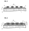
der Figur 1 umschlossenen Bereichs des Verformungskörpers mit einem aufgeklebten Dehnmessstreifen, Figur 3- einen einzelnen auf einen Verformungskörper aufgeklebten Dehnmessstreifen im Schnitt,
Figur 4- einen einzelnen auf einen Verformungskörper aufgeklebten Dehnmessstreifen, der mit einer Schutzbeschichtung gegen eindringende Feuchtigkeit versehen ist, im Schnitt.
- FIG. 1
- a deformation body of a load cell with strain gauges mounted on the respective regions of low material thickness forming the bending bearings in a three-dimensional representation,
- FIG. 2
- an enlarged, three - dimensional representation of the circle A in the
FIG. 1 enclosed region of the deformation body with a glued strain gauge, - FIG. 3
- a single on a deformation body glued strain gauges in section,
- FIG. 4
- a single on a deformation body glued strain gauge, which is provided with a protective coating against moisture penetrating, in section.
Die
Die Klebeschicht 16 besteht aus einem anorganisch-organischen Hybridpolymer. Diese Stoffklasse, die zum Beispiel unter dem Handelsnamen ORMOCER® bekannt ist, weisen sowohl anorganische als auch organische Netzwerkstrukturen auf. Der Aufbau der anorganischen silikatischen Netzwerkstruktur erfolgt im Sol-Gel-Verfahren über die gesteuerte Hydrolyse und Kondensation von Alkoxisilanen, wobei sich durch zusätzliche in den Prozess einbezogene Metallalkoxide das silikatische Netzwerk gezielt modifizieren lässt. Durch Polymerisation von organofunktionellen Gruppen, welche durch die Organoalkoxylane in das Material eingebracht werden, wird zusätzlich ein organisches Netzwerk aufgebaut. Reaktive Methacrylat-, Epoxy- oder Vinylgruppen werden durch thermische oder photochemische Einwirkung polymerisiert. Als Beispiele für das Klebematerial können die in der
Neben guten Haftungseigenschaften, weisen die anorganisch-organischen Hybridpolymere, insbesondere, wenn sie durch Füllstoffe, wie funktionalisierte SiO2-Partikel oder Al2O3-Partikel modifiziert sind, eine gegenüber den Epoxid-Klebematerialien gemäss dem Stand der Technik um einen Faktor 5 bis10 erhöhte Barrierewirkung gegenüber eindringender Feuchtigkeit, beispielsweise Wasserdampf auf. Auf diese Weise wird das Eindringen von Feuchtigkeit über die Klebeschicht 16 in den Polyimid-Träger 15, welche zu einem unerwünschten Quellen dieses Materials führt, verringert.In addition to good adhesion properties, the inorgano-organic hybrid polymers, in particular when modified by fillers, such as functionalized SiO 2 particles or Al 2 O 3 particles, have a factor of from 5 to 10 compared to the epoxy adhesive materials according to the prior art increased barrier effect against penetrating moisture, such as water vapor. In this way, the penetration of moisture via the
In der
Das anorganisch-organischen Hybridpolymer geht eine kovalente Bindung zu der Aluminiumoxidschicht 19 ein und gewährleistet dadurch eine gute Haftung. Insbesondere findet, bedingt durch die Porosität der Aluminiumoxidschicht 19, eine mechanische Verankerung der Klebeschicht 16 in dieser statt. Die Aluminiumoxidschicht 19 kann durch geeignete Vorbehandlung des Aluminium-Verformungskörpers, namentlich Erwärmen auf Temperaturen unterhalb 100°C in einer Sauerstoffatmosphäre oder durch chemische oder elektrochemische Behandlung gezielt in ihrer Schichtdicke vergrössert und hinsichtlich ihrer Porosität modifiziert werden, um die Haftung zu verstärken.The inorganic-organic hybrid polymer forms a covalent bond to the
In der
Der Mehrlagenschicht 20 ist eine ausebnende Schicht 21 aus einem Polymer, beispielsweise eine Acrylat- oder Methacrylat-Polymerschicht oder eine anorganisch-organische Hybridpolymerschicht, in bevorzugter Weise eine, die der Klebeschicht 16 entspricht, unterlegt. Eine solche Schicht 21 glättet die Oberfläche des Dehnmessstreifens 13, insbesondere im Bereich der Kanten, beispielsweise an denjenigen der Widerstandsbahn 14, wodurch deren Flankensteilheit reduziert wird. Ausserdem werden Unregelmässigkeiten der Oberfläche oder gar Fehlstellen oder Schmutzpartikel, sei dies nun auf der Widerstandsbahn 14 oder dem Träger 15 in ausgleichender Weise abgedeckt. Ausserdem wird durch die ausebnende Polymerschicht 21 die Wahrscheinlichkeit des Entstehens oder Anheftens von Mikroporen oder Haarrissen in einer darauf aufgebrachten anorganischen Schutzschicht 20 reduziert. Infolgedessen wird die Ausbildung einer fehlstellenarmen auf die ausebnende Schicht 21 aufzubringende bzw. aufgebrachten mehrlagigen anorganischen Schutzschicht 20 begünstigt.The multi-layer 20 is a
Die Schutzbeschichtung kann nun bereits auf dem zu applizierenden Dehnmessstreifen 13 vorhanden sein oder auf den mit dem Verformungskörper 1 mittels der Klebeschicht 16 verbundenen Dehnmessstreifen 13 aufgebracht werden. In letzterem Falle erstrecken sich ein Teil der Schutzschicht 20 und der dieser unterlegten ausebnenden Polymerschicht 21 über den Dehnmessstreifen 13 hinaus und bedecken mindestens einen Teil des Verformungskörpers 1, insbesondere die an den Dehnmessstreifen 13 angrenzenden Bereiche des Verformungskörpers 1. Dadurch wird das Eindringen von Feuchtigkeit in den Träger 15 weiter verringert.The protective coating can now already be present on the strain gauges 13 to be applied or applied to the strain gauges 13 connected to the
Die Klebemasse liegt als Lösung der vorkondensierten anorganischen Komponenten und der organischen Komponenten, vorzugsweise reaktive organische Gruppen, in einem herkömmlichen Lacklösungsmittel vor. Durch den Lösungsmittelanteil kann die Viskosität der Klebemasse nach Bedarf der gewählten Methode zum Auftragen, zum Beispiel Streichen, Schleudern, Sprühen, Walzen oder Tampondruck, angepasst werden.The adhesive is present as a solution of the precondensed inorganic components and the organic components, preferably reactive organic groups, in a conventional lacquer solvent. As a result of the solvent content, the viscosity of the adhesive can be adapted as required to the chosen method of application, for example brushing, spinning, spraying, rolling or pad printing.
Das bevorzugte Verfahren zum Aufbringen eines Dehnmessstreifens 13 auf den Verformungskörper 1 einer Kraftmesszelle sieht vor, ein anorganisch-organisches Hybridpolymer in gelöster Form mittels Tampondruckverfahren auf den Verformungskörper aufzubringen und anschliessend den Dehnmessstreifen 13 auf die mit der Lösung versehene Fläche absetzen und leicht anzudrücken. Durch Erwärmen bei Temperaturen zwischen 80°C und 130°C, wobei der Dehnmessstreifen mit einem Druck, der zwischen 100kN/m2 und 1000kN/ m2 liegt, beaufschlagt wird, wird die Klebeschicht 16 durch Vernetzung aushärten. Die Aushärtetemperatur hängt von der Wahl der Komponenten des anorganisch-organischen Hybridpolymers ab und ist hinsichtlich eines möglichst geringen Anstiegs der Viskoelastizität des Verformungskörpers mit der Dauer der Einwirkung der erhöhten Temperatur, welche zwischen einer und drei Stunden betragen kann, abgestimmt. Es sei an dieser Stelle erwähnt, dass die Viskoelastizität von Aluminium bei einer Erniedrigung der Aushärtetemperatur von 150°C auf 100°C bereits um 50% reduziert werden kann.The preferred method for applying a
Das Tampondruckverfahren sieht vor, mittels eines elastisch verformbaren Kissens, dem Tampon, das anorganisch-organische Hybridpolymer in gelöster Form - die Klebemasse - aus einer mit einer geätzten Vertiefung versehenen Platte, dem Klischee, aufzunehmen und auf dem Verformungskörper direkt an die Stelle des zu befestigenden Dehnmessstreifens zu deponieren. Durch eine angepasste Viskosität der Lösung einerseits und durch die Verformbarkeit des Tampons andererseits wird beim Auftragen die Form der Klebemasse beibehalten und es wird eine gleichmässige Klebeschicht 16 erzeugt.The tampon printing process provides, by means of an elastically deformable pad, the tampon, the inorganic-organic hybrid polymer in dissolved form - the adhesive - from a plate provided with an etched depression record, the cliché, and on the deformation body directly in the place to be fastened Strain gauge to deposit. By an adapted viscosity of the solution on the one hand and by the deformability of the tampon on the other hand, the shape of the adhesive is maintained during application and it is a uniform
Die mit einem Dehnmessstreifen, der mittels einer erfindungsgemäsen Klebeschicht aufgebracht wurde, versehene Kraftmesszelle wurde in einer bevorzugten Ausgestaltung beschrieben und dargestellt. Anhand der erfindungsgemässen Lehre sind jedoch weitere fachmännische Ausgestaltungen realisierbar. Zum Beispiel ist das Material für den Träger des Dehnmessstreifens nicht auf Polyimid beschränkt. Es können auch andere Polymere wie Epoxide, Phenolharze, Melamine und Ketone für Dehnmessstreifen, die in der Wägetechnologie Einsatz finden, verwendet werden. Abhängig vom Trägermaterial ist dann das Material für die Klebeschicht zu verwenden. Dies betrifft insbesondere die Variation der polymeren Komponente des anorganisch-organischen Hybridpolymers.The force measuring cell provided with a strain gauge, which was applied by means of an adhesive layer according to the invention, has been described and illustrated in a preferred embodiment. On the basis of the teaching according to the invention, however, further expert designs can be realized. For example, the material for the beam of the strain gauge is not limited to polyimide. Other polymers such as epoxies, phenolic resins, melamines and ketones for strain gauges used in weighing technology can also be used. Depending on the carrier material then the material for the adhesive layer is to be used. This relates in particular to the variation of the polymeric component of the inorganic-organic hybrid polymer.
- 11
- Verformungskörperdeformable body
- 22
- Biegestellebend
- 33
- Biegestellebend
- 44
- Biegestellebend
- 55
- Biegestellebend
- 66
- bogenförmig erweiterter Randbereicharcuate extended edge area
- 77
- bogenförmig erweiterter Randbereicharcuate extended edge area
- 88th
- Ausnehmungrecess
- 99
- Lastaufnehmerload sensor
- 1010
- Gewindethread
- 1111
- Feststehender TeilFixed part
- 1212
- Oberseite des VerformungskörpersTop of the deformation body
- 1313
- DehnmessstreifenStrain
- 1414
- Widerstandsbahnresistance path
- 1515
- Trägercarrier
- 1616
- Klebeschichtadhesive layer
- 1717
- Anschlusselektrodenterminal electrodes
- 1818
- Aluminiumbereich des VerformungskörpersAluminum region of the deformation body
- 1919
- Aluminiumoxid-Schicht auf dem VerformungskörperAluminum oxide layer on the deformation body
- 2020
- Schutzschichtprotective layer
- 2121
- Ausebnende SchichtExpanding layer
- 2222
- Barriereschichtbarrier layer
- 2323
- Zwischenschichtinterlayer
Claims (9)
- Force-measuring cell with a deformable body (1) and with at least one strain gauge (13) which is installed on the deformable body (1) by means of an adhesive layer (16) and which has a strain-sensitive electrical resistor track (14) arranged on a polymer carrier substrate (15), characterized in that the adhesive layer (16) consists of an inorganic-organic hybrid polymer, and further that the at least one strain gauge (13) is provided with a protective coating (20) against moisture penetration, wherein the protective coating (20) is underlaid with a surface-smoothing layer (21) consisting of a polymer or of an inorganic-organic hybrid polymer, and wherein the protective coating (20) is a multilayered coating which is composed of barrier layers and intermediate layers, wherein the barrier layers are inorganic materials and the intermediate layers are polymers or inorganic materials.
- Force-measuring cell according to claim 1, characterized in that the multilayered coating which is configured as protective coating (20) is composed of an alternating sequence of a barrier layer (22) of silicon nitride and an intermediate layer (23) of silicon oxide.
- Force-measuring cell according to claim 1 or 2, characterized in that the deformable body (1) is made of aluminum, wherein the deformable body (1) has on its surface an aluminum oxide layer (19) which in comparison to a natural oxide layer has an increased thickness and/or an increased porosity due to a chemical, electrochemical or thermal treatment, whereby the bond to the adhesive layer (16) is strengthened by a mechanical anchoring of the adhesive layer (16) in the aluminum oxide layer (19).
- Method of fastening a strain gauge (13) on a deformable body (1) of a force-measuring cell, characterized in that an adhesive compound consisting of an inorganic-organic hybrid polymer in solution is applied to the deformable body (1) in order to produce an adhesive layer (16), that the strain gauge (13) is placed on the adhesive compound, and that the adhesive layer (16) is subsequently hardened at a temperature between 80°C and 130°C by exposing the deformable body (1) with the strain gauge (13) to the increased temperature for a duration between half an hour and three hours, and further characterized in that the at least one strain gauge (13) is given a layered protective covering against moisture penetration, wherein said layered covering comprises a surface-smoothing layer (21) which consists of a polymer or of an inorganic-organic hybrid polymer and is applied directly to the strain gauge, and said layered covering further comprises a protective coating (20) configured as a multilayered coating which is composed of barrier layers and intermediate layers, wherein the barrier layers are inorganic materials and the intermediate layers are polymers or inorganic materials.
- Method according to claim 4, characterized in that the strain gauge (13) is subjected to a contact pressure between 100 kN/m2 and 1000 kN/m2 during the hardening.
- Method according to claim 4 or 5 for a deformable body (1) of aluminum, characterized in that prior to applying the adhesive compound for producing the adhesive layer (16), the deformable body (1) is heated under oxygen atmosphere at a temperature between 40°C and 100°C in order to increase the aluminum oxide layer (19) on the surface of the deformable body (1).
- Method according to claim 4 or 5 for a deformable body (1) of aluminum, characterized in that prior to applying the adhesive compound for producing the adhesive layer (16), the deformable body (1) is subjected to a chemical or electrochemical treatment in order to increase the aluminum oxide layer (19) on the surface of the deformable body (1).
- Method according to one of the claims 4 to 7, characterized in that the application of the adhesive compound for producing the adhesive layer (16) is performed by means of a tampon-printing method.
- Method according to one of the claims 4 to 8, characterized in that the layered protective covering is applied to a strain gauge (13) which has already been installed on a deformable body (1).
Priority Applications (6)
| Application Number | Priority Date | Filing Date | Title |
|---|---|---|---|
| DE502004010000T DE502004010000D1 (en) | 2004-01-27 | 2004-01-27 | Load cells with strain gauges with inorganic-organic hybrid polymer (ORMOCER) adhesive layer |
| AT04075198T ATE441843T1 (en) | 2004-01-27 | 2004-01-27 | FORCE MEASUREMENT CELL WITH STRAIN GAUGES WITH ADHESIVE LAYER MADE OF INORGANIC-ORGANIC HYBRID POLYMER (ORMOCER) |
| EP04075198A EP1560010B1 (en) | 2004-01-27 | 2004-01-27 | Load cell with strain gauge with adhesive layer of inorganic-organic hybrid-polymer (ORMOCER) |
| JP2005007547A JP2005214969A (en) | 2004-01-27 | 2005-01-14 | Technique for adhering strain gauge to deformable body of force-measuring cell |
| CNB200510005766XA CN100538293C (en) | 2004-01-27 | 2005-01-25 | The bonding of the deformable body of foil gauge and load-sensing unit |
| US11/043,161 US7243558B2 (en) | 2004-01-27 | 2005-01-27 | Bonding of strain gauges to the deformable body of a force-measuring cell |
Applications Claiming Priority (1)
| Application Number | Priority Date | Filing Date | Title |
|---|---|---|---|
| EP04075198A EP1560010B1 (en) | 2004-01-27 | 2004-01-27 | Load cell with strain gauge with adhesive layer of inorganic-organic hybrid-polymer (ORMOCER) |
Publications (2)
| Publication Number | Publication Date |
|---|---|
| EP1560010A1 EP1560010A1 (en) | 2005-08-03 |
| EP1560010B1 true EP1560010B1 (en) | 2009-09-02 |
Family
ID=34639445
Family Applications (1)
| Application Number | Title | Priority Date | Filing Date |
|---|---|---|---|
| EP04075198A Expired - Lifetime EP1560010B1 (en) | 2004-01-27 | 2004-01-27 | Load cell with strain gauge with adhesive layer of inorganic-organic hybrid-polymer (ORMOCER) |
Country Status (6)
| Country | Link |
|---|---|
| US (1) | US7243558B2 (en) |
| EP (1) | EP1560010B1 (en) |
| JP (1) | JP2005214969A (en) |
| CN (1) | CN100538293C (en) |
| AT (1) | ATE441843T1 (en) |
| DE (1) | DE502004010000D1 (en) |
Cited By (1)
| Publication number | Priority date | Publication date | Assignee | Title |
|---|---|---|---|---|
| US20220341790A1 (en) * | 2019-09-05 | 2022-10-27 | Minebea Mitsumi Inc. | Sensor module and strain detecting device |
Families Citing this family (32)
| Publication number | Priority date | Publication date | Assignee | Title |
|---|---|---|---|---|
| CN101309638A (en) | 2005-09-06 | 2008-11-19 | 神经系统检测公司 | Disposable, multi-purpose cardiovascular autonomic neuropathy testing device |
| DE102006012831A1 (en) | 2006-03-21 | 2007-10-04 | Hottinger Baldwin Messtechnik Gmbh | Strain gauges and transducers with at least one strain gauge |
| JP2008002870A (en) * | 2006-06-21 | 2008-01-10 | Ishida Co Ltd | Load cell, and its manufacturing method |
| EP2250476A4 (en) * | 2008-02-27 | 2011-04-20 | Measurement Spec Inc | A low pressure transducer using beam and diaphragm |
| FR2937725B1 (en) * | 2008-10-24 | 2011-01-21 | Snecma | METHOD FOR INSTALLING AND PROTECTING A SENSOR ON A SUBSTRATE |
| FR2944865B1 (en) * | 2009-04-27 | 2011-06-24 | Commissariat Energie Atomique | STRAIN SENSOR AND METHOD FOR PRODUCING THE SAME |
| DE102010012670B4 (en) * | 2010-03-24 | 2020-09-03 | Soehnle Industrial Solutions Gmbh | Forklift truck with a device for detecting a weight load |
| CN102221430B (en) * | 2010-04-13 | 2013-07-10 | 精量电子(深圳)有限公司 | Method for bonding foil gauge with micro melting |
| JP5893857B2 (en) * | 2011-06-24 | 2016-03-23 | 株式会社ミツトヨ | Scale scale protection structure |
| DE102011053505A1 (en) * | 2011-09-12 | 2013-03-14 | Scambia Holdings Cyprus Ltd. | support unit |
| CN102645156B (en) * | 2012-04-25 | 2014-11-12 | 中航电测仪器股份有限公司 | Method for improving quality of resistance strain gauge with phenolic aldehyde substrate |
| US9562804B2 (en) * | 2013-03-14 | 2017-02-07 | Larry D. Santi | Forklift scale, load cell thereof and method of measuring a forklift load |
| FR3023909B1 (en) * | 2014-07-17 | 2020-11-20 | Centre Techn Ind Mecanique | PROCESS FOR MAKING A STRENGTH SENSOR AND INSTALLATION FOR IMPLEMENTATION |
| DE102014013812A1 (en) * | 2014-09-23 | 2016-03-24 | Westfalia-Automotive Gmbh | Trailer coupling with a sensor |
| JP2016125977A (en) * | 2015-01-08 | 2016-07-11 | 昭和電工株式会社 | Strain gauge adhesion method |
| JP2017067764A (en) * | 2015-09-29 | 2017-04-06 | ミネベアミツミ株式会社 | Strain gauge, load sensor, and manufacturing method for strain gauge |
| CN105803381B (en) * | 2016-03-30 | 2018-04-13 | 中国人民解放军装甲兵工程学院 | A kind of high-temp strain spraying method based on foil gauge installation |
| DE102016108541A1 (en) * | 2016-05-09 | 2017-11-09 | Bosal Nederland B.V. | Device for pulling a trailer and / or holding a load carrier unit |
| CN108120369A (en) * | 2016-11-28 | 2018-06-05 | 梅特勒-托利多(常州)精密仪器有限公司 | The method and device of fixed foil gauge |
| JP2019066454A (en) | 2017-09-29 | 2019-04-25 | ミネベアミツミ株式会社 | Strain gauge and sensor module |
| JP6793103B2 (en) | 2017-09-29 | 2020-12-02 | ミネベアミツミ株式会社 | Strain gauge |
| JP2019066453A (en) | 2017-09-29 | 2019-04-25 | ミネベアミツミ株式会社 | Strain gauge |
| JP2019066312A (en) | 2017-09-29 | 2019-04-25 | ミネベアミツミ株式会社 | Strain gauge |
| JP2019082424A (en) * | 2017-10-31 | 2019-05-30 | ミネベアミツミ株式会社 | Strain gauge |
| JP2019113411A (en) | 2017-12-22 | 2019-07-11 | ミネベアミツミ株式会社 | Strain gauge and sensor module |
| JP2019184344A (en) | 2018-04-05 | 2019-10-24 | ミネベアミツミ株式会社 | Strain gauge and manufacturing method therefor |
| EP3617683A1 (en) * | 2018-08-31 | 2020-03-04 | Mettler Toledo (Changzhou) Precision Instrument Ltd. | Method of insulating a strain gauge against moisture penetration |
| JPWO2020085247A1 (en) | 2018-10-23 | 2021-09-16 | ミネベアミツミ株式会社 | Accelerator pedal, steering, door, door opening and closing system |
| CN112284581B (en) * | 2020-10-27 | 2022-04-15 | 湖北长江新型显示产业创新中心有限公司 | Sensor, display panel and electronic equipment |
| FR3116339B1 (en) * | 2020-11-16 | 2022-11-11 | Commissariat Energie Atomique | Inorganic Strain Gauge |
| CN113532259A (en) * | 2021-07-23 | 2021-10-22 | 中国航发贵阳发动机设计研究所 | Process for sticking strain gauge by using M-610 adhesive |
| US11874192B2 (en) * | 2021-08-04 | 2024-01-16 | Vishay Advanced Technologies Ltd. | Elongate force sensor assembly with throughgoing bore |
Citations (3)
| Publication number | Priority date | Publication date | Assignee | Title |
|---|---|---|---|---|
| US5631622A (en) * | 1994-02-15 | 1997-05-20 | Hottinger Baldwin Messtechnik Gmbh | Strain gage and measuring transducer and method of producing the same |
| US6283578B1 (en) * | 1996-06-28 | 2001-09-04 | Pelikan Produktions Ag | Hydrophobic coating for ink jet printing heads |
| EP1308705A1 (en) * | 2001-10-27 | 2003-05-07 | Robert Bosch Gmbh | Manufacturing procedure of a sensor element and use of such an element |
Family Cites Families (19)
| Publication number | Priority date | Publication date | Assignee | Title |
|---|---|---|---|---|
| US3935636A (en) * | 1974-03-29 | 1976-02-03 | Tyco Laboratories, Inc. | Method of making a pressure transducer |
| GB2051819A (en) * | 1979-06-29 | 1981-01-21 | Bofors America | Epoxy resin adhesive composition |
| GB8303555D0 (en) * | 1983-02-09 | 1983-03-16 | Strain Measurement Dev Ltd | Strain gauges |
| CH677988A5 (en) * | 1986-07-30 | 1991-07-15 | Actron Entwicklungs Ag | |
| JP2539639B2 (en) * | 1987-10-28 | 1996-10-02 | 株式会社共和電業 | High temperature strain gauge and its attachment structure |
| JPH01169303A (en) * | 1987-12-25 | 1989-07-04 | Sumitomo Heavy Ind Ltd | Manufacture of strain detector |
| JP2651556B2 (en) * | 1992-12-11 | 1997-09-10 | 株式会社 寺岡精工 | Load cell and manufacturing method thereof |
| JPH06281511A (en) * | 1993-03-26 | 1994-10-07 | Tokyo Electric Co Ltd | Strain sensor |
| DE4320666A1 (en) * | 1993-06-22 | 1995-01-05 | Hottinger Messtechnik Baldwin | Strain gauge (foil strain gauge) |
| JPH0735628A (en) * | 1993-07-16 | 1995-02-07 | Kyowa Electron Instr Co Ltd | Structure and method for covering strain gate affixed part |
| JPH0744039A (en) * | 1993-07-27 | 1995-02-14 | Toshiba Lighting & Technol Corp | Plane heater |
| JPH098326A (en) * | 1995-06-15 | 1997-01-10 | Matsushita Electric Works Ltd | Semiconductor pressure sensor |
| JP3520652B2 (en) * | 1996-02-08 | 2004-04-19 | 株式会社デンソー | Semiconductor force sensor |
| CA2320857A1 (en) * | 1998-02-18 | 1999-08-26 | Honeywell Data Instruments, Inc. | Electrically insulated strain gage |
| JP3336992B2 (en) * | 1999-04-09 | 2002-10-21 | 株式会社寺岡精工 | Load cell |
| JP3613086B2 (en) * | 1999-08-31 | 2005-01-26 | 荒川化学工業株式会社 | Composition for organic-inorganic hybrid polyurethane and organic-inorganic hybrid polyurethane |
| JP4635312B2 (en) * | 2000-09-21 | 2011-02-23 | 日立化成工業株式会社 | Adhesive composition, circuit connection material, adhesive composition for circuit connection, connector and semiconductor device |
| JP2002139389A (en) * | 2000-10-30 | 2002-05-17 | Nagano Keiki Co Ltd | Sensing element for measuring load |
| JP2002365146A (en) * | 2001-06-12 | 2002-12-18 | Ishida Co Ltd | Load cell |
-
2004
- 2004-01-27 DE DE502004010000T patent/DE502004010000D1/en not_active Expired - Lifetime
- 2004-01-27 EP EP04075198A patent/EP1560010B1/en not_active Expired - Lifetime
- 2004-01-27 AT AT04075198T patent/ATE441843T1/en not_active IP Right Cessation
-
2005
- 2005-01-14 JP JP2005007547A patent/JP2005214969A/en active Pending
- 2005-01-25 CN CNB200510005766XA patent/CN100538293C/en not_active Expired - Fee Related
- 2005-01-27 US US11/043,161 patent/US7243558B2/en active Active
Patent Citations (3)
| Publication number | Priority date | Publication date | Assignee | Title |
|---|---|---|---|---|
| US5631622A (en) * | 1994-02-15 | 1997-05-20 | Hottinger Baldwin Messtechnik Gmbh | Strain gage and measuring transducer and method of producing the same |
| US6283578B1 (en) * | 1996-06-28 | 2001-09-04 | Pelikan Produktions Ag | Hydrophobic coating for ink jet printing heads |
| EP1308705A1 (en) * | 2001-10-27 | 2003-05-07 | Robert Bosch Gmbh | Manufacturing procedure of a sensor element and use of such an element |
Cited By (1)
| Publication number | Priority date | Publication date | Assignee | Title |
|---|---|---|---|---|
| US20220341790A1 (en) * | 2019-09-05 | 2022-10-27 | Minebea Mitsumi Inc. | Sensor module and strain detecting device |
Also Published As
| Publication number | Publication date |
|---|---|
| EP1560010A1 (en) | 2005-08-03 |
| ATE441843T1 (en) | 2009-09-15 |
| CN100538293C (en) | 2009-09-09 |
| US7243558B2 (en) | 2007-07-17 |
| DE502004010000D1 (en) | 2009-10-15 |
| JP2005214969A (en) | 2005-08-11 |
| CN1648625A (en) | 2005-08-03 |
| US20050160837A1 (en) | 2005-07-28 |
Similar Documents
| Publication | Publication Date | Title |
|---|---|---|
| EP1560010B1 (en) | Load cell with strain gauge with adhesive layer of inorganic-organic hybrid-polymer (ORMOCER) | |
| EP1560011B1 (en) | Strain gauge with moisture protection by an inhomogeneous inorganic layer upon a smoothing polymer layer (ORMOCER) and an arrangement of slits | |
| EP1384980A1 (en) | Moisture protection for an electromechanical transducer | |
| EP2126511B1 (en) | Optical strain gauge | |
| EP0596293B1 (en) | Strain gauge and transducer using same | |
| DE69727793T2 (en) | Composite material made of silicone rubber and polyester resin | |
| EP1999445B1 (en) | Strain gauge and measurement variable sensor having at least one strain gauge | |
| EP2881249B1 (en) | Natural fiber polymer composite and eco-friendly lightweight base material for automotive interior | |
| EP0096156B1 (en) | Process for the quasi-hermetic, almost reactionless covering of sensitive physical structures, especially strain gauges | |
| DE3724290A1 (en) | ELECTRODE FOR PIEZOELECTRIC COMPOSITES | |
| DE102016120906B4 (en) | Input device with an array of force sensors and partially hardened interlayer | |
| DE102010021914A1 (en) | Physical size sensor device and manufacturing method thereof | |
| DE102012100231B4 (en) | Semiconductor chip | |
| DE102014200443B4 (en) | Sensor element for determining strains | |
| DE102006023724A1 (en) | Measuring cell device for pressure sensor, has membrane and strength measuring element, impinged with pressure for measuring fluid, where measuring element is connected with side facing away from pressure of membrane | |
| EP1263060A2 (en) | Manufacturing method for a flat multilayer device and corresponding device | |
| DE102010008397A1 (en) | Sensor system for the determination of fatigue on metallic components | |
| EP1308705A1 (en) | Manufacturing procedure of a sensor element and use of such an element | |
| DE102010054970A1 (en) | Device for converting elongation and/or upsetting into electric signal in elongation measuring film for manufacturing e.g. pressure sensor, has support whose upper surface is planarized and/or passivated by electrically isolated layer | |
| EP1200986A1 (en) | Passivation layer structure | |
| DE102017218363A1 (en) | SURFACE-STRUCTURED POLYMERIC BODIES AND METHOD FOR THE PRODUCTION THEREOF | |
| EP1896256B1 (en) | Method for producing a composite structure, and a composite structure produced thereby | |
| DE102011119349A1 (en) | Method for manufacturing thin layer sense element i.e. strain gauge, in industry, involves producing sensor substrate by applying liquid polyimide phase to carrier, and carrying out poly-imidization by action of elevated temperature | |
| EP0401536A2 (en) | Measuring scale | |
| DE102013207779A1 (en) | Multilayer structure with alternating conductive and non-conductive layers |
Legal Events
| Date | Code | Title | Description |
|---|---|---|---|
| PUAI | Public reference made under article 153(3) epc to a published international application that has entered the european phase |
Free format text: ORIGINAL CODE: 0009012 |
|
| AK | Designated contracting states |
Kind code of ref document: A1 Designated state(s): AT BE BG CH CY CZ DE DK EE ES FI FR GB GR HU IE IT LI LU MC NL PT RO SE SI SK TR |
|
| AX | Request for extension of the european patent |
Extension state: AL LT LV MK |
|
| 17P | Request for examination filed |
Effective date: 20060202 |
|
| AKX | Designation fees paid |
Designated state(s): AT BE BG CH CY CZ DE DK EE ES FI FR GB GR HU IE IT LI LU MC NL PT RO SE SI SK TR |
|
| RAP1 | Party data changed (applicant data changed or rights of an application transferred) |
Owner name: METTLER-TOLEDO AG |
|
| 17Q | First examination report despatched |
Effective date: 20061108 |
|
| 17Q | First examination report despatched |
Effective date: 20061108 |
|
| GRAP | Despatch of communication of intention to grant a patent |
Free format text: ORIGINAL CODE: EPIDOSNIGR1 |
|
| GRAS | Grant fee paid |
Free format text: ORIGINAL CODE: EPIDOSNIGR3 |
|
| GRAA | (expected) grant |
Free format text: ORIGINAL CODE: 0009210 |
|
| AK | Designated contracting states |
Kind code of ref document: B1 Designated state(s): AT BE BG CH CY CZ DE DK EE ES FI FR GB GR HU IE IT LI LU MC NL PT RO SE SI SK TR |
|
| REG | Reference to a national code |
Ref country code: CH Ref legal event code: EP |
|
| REG | Reference to a national code |
Ref country code: IE Ref legal event code: FG4D Free format text: LANGUAGE OF EP DOCUMENT: GERMAN |
|
| REF | Corresponds to: |
Ref document number: 502004010000 Country of ref document: DE Date of ref document: 20091015 Kind code of ref document: P |
|
| PG25 | Lapsed in a contracting state [announced via postgrant information from national office to epo] |
Ref country code: SE Free format text: LAPSE BECAUSE OF FAILURE TO SUBMIT A TRANSLATION OF THE DESCRIPTION OR TO PAY THE FEE WITHIN THE PRESCRIBED TIME-LIMIT Effective date: 20090902 Ref country code: FI Free format text: LAPSE BECAUSE OF FAILURE TO SUBMIT A TRANSLATION OF THE DESCRIPTION OR TO PAY THE FEE WITHIN THE PRESCRIBED TIME-LIMIT Effective date: 20090902 |
|
| NLV1 | Nl: lapsed or annulled due to failure to fulfill the requirements of art. 29p and 29m of the patents act | ||
| PG25 | Lapsed in a contracting state [announced via postgrant information from national office to epo] |
Ref country code: NL Free format text: LAPSE BECAUSE OF FAILURE TO SUBMIT A TRANSLATION OF THE DESCRIPTION OR TO PAY THE FEE WITHIN THE PRESCRIBED TIME-LIMIT Effective date: 20090902 Ref country code: SI Free format text: LAPSE BECAUSE OF FAILURE TO SUBMIT A TRANSLATION OF THE DESCRIPTION OR TO PAY THE FEE WITHIN THE PRESCRIBED TIME-LIMIT Effective date: 20090902 |
|
| PG25 | Lapsed in a contracting state [announced via postgrant information from national office to epo] |
Ref country code: CY Free format text: LAPSE BECAUSE OF FAILURE TO SUBMIT A TRANSLATION OF THE DESCRIPTION OR TO PAY THE FEE WITHIN THE PRESCRIBED TIME-LIMIT Effective date: 20090902 |
|
| REG | Reference to a national code |
Ref country code: IE Ref legal event code: FD4D |
|
| PG25 | Lapsed in a contracting state [announced via postgrant information from national office to epo] |
Ref country code: CZ Free format text: LAPSE BECAUSE OF FAILURE TO SUBMIT A TRANSLATION OF THE DESCRIPTION OR TO PAY THE FEE WITHIN THE PRESCRIBED TIME-LIMIT Effective date: 20090902 Ref country code: IE Free format text: LAPSE BECAUSE OF FAILURE TO SUBMIT A TRANSLATION OF THE DESCRIPTION OR TO PAY THE FEE WITHIN THE PRESCRIBED TIME-LIMIT Effective date: 20090902 Ref country code: PT Free format text: LAPSE BECAUSE OF FAILURE TO SUBMIT A TRANSLATION OF THE DESCRIPTION OR TO PAY THE FEE WITHIN THE PRESCRIBED TIME-LIMIT Effective date: 20100104 Ref country code: RO Free format text: LAPSE BECAUSE OF FAILURE TO SUBMIT A TRANSLATION OF THE DESCRIPTION OR TO PAY THE FEE WITHIN THE PRESCRIBED TIME-LIMIT Effective date: 20090902 Ref country code: EE Free format text: LAPSE BECAUSE OF FAILURE TO SUBMIT A TRANSLATION OF THE DESCRIPTION OR TO PAY THE FEE WITHIN THE PRESCRIBED TIME-LIMIT Effective date: 20090902 Ref country code: ES Free format text: LAPSE BECAUSE OF FAILURE TO SUBMIT A TRANSLATION OF THE DESCRIPTION OR TO PAY THE FEE WITHIN THE PRESCRIBED TIME-LIMIT Effective date: 20091213 |
|
| PG25 | Lapsed in a contracting state [announced via postgrant information from national office to epo] |
Ref country code: SK Free format text: LAPSE BECAUSE OF FAILURE TO SUBMIT A TRANSLATION OF THE DESCRIPTION OR TO PAY THE FEE WITHIN THE PRESCRIBED TIME-LIMIT Effective date: 20090902 |
|
| PLBE | No opposition filed within time limit |
Free format text: ORIGINAL CODE: 0009261 |
|
| STAA | Information on the status of an ep patent application or granted ep patent |
Free format text: STATUS: NO OPPOSITION FILED WITHIN TIME LIMIT |
|
| PG25 | Lapsed in a contracting state [announced via postgrant information from national office to epo] |
Ref country code: DK Free format text: LAPSE BECAUSE OF FAILURE TO SUBMIT A TRANSLATION OF THE DESCRIPTION OR TO PAY THE FEE WITHIN THE PRESCRIBED TIME-LIMIT Effective date: 20090902 |
|
| BERE | Be: lapsed |
Owner name: METTLER-TOLEDO A.G. Effective date: 20100131 |
|
| 26N | No opposition filed |
Effective date: 20100603 |
|
| PG25 | Lapsed in a contracting state [announced via postgrant information from national office to epo] |
Ref country code: MC Free format text: LAPSE BECAUSE OF NON-PAYMENT OF DUE FEES Effective date: 20100131 |
|
| PG25 | Lapsed in a contracting state [announced via postgrant information from national office to epo] |
Ref country code: GR Free format text: LAPSE BECAUSE OF FAILURE TO SUBMIT A TRANSLATION OF THE DESCRIPTION OR TO PAY THE FEE WITHIN THE PRESCRIBED TIME-LIMIT Effective date: 20091203 |
|
| PGFP | Annual fee paid to national office [announced via postgrant information from national office to epo] |
Ref country code: FR Payment date: 20101221 Year of fee payment: 8 |
|
| PG25 | Lapsed in a contracting state [announced via postgrant information from national office to epo] |
Ref country code: BE Free format text: LAPSE BECAUSE OF NON-PAYMENT OF DUE FEES Effective date: 20100131 |
|
| PG25 | Lapsed in a contracting state [announced via postgrant information from national office to epo] |
Ref country code: IT Free format text: LAPSE BECAUSE OF FAILURE TO SUBMIT A TRANSLATION OF THE DESCRIPTION OR TO PAY THE FEE WITHIN THE PRESCRIBED TIME-LIMIT Effective date: 20090902 |
|
| PGFP | Annual fee paid to national office [announced via postgrant information from national office to epo] |
Ref country code: GB Payment date: 20101215 Year of fee payment: 8 |
|
| PG25 | Lapsed in a contracting state [announced via postgrant information from national office to epo] |
Ref country code: AT Free format text: LAPSE BECAUSE OF NON-PAYMENT OF DUE FEES Effective date: 20100127 |
|
| PGFP | Annual fee paid to national office [announced via postgrant information from national office to epo] |
Ref country code: CH Payment date: 20110103 Year of fee payment: 8 |
|
| REG | Reference to a national code |
Ref country code: CH Ref legal event code: PL |
|
| GBPC | Gb: european patent ceased through non-payment of renewal fee |
Effective date: 20120127 |
|
| PG25 | Lapsed in a contracting state [announced via postgrant information from national office to epo] |
Ref country code: BG Free format text: LAPSE BECAUSE OF FAILURE TO SUBMIT A TRANSLATION OF THE DESCRIPTION OR TO PAY THE FEE WITHIN THE PRESCRIBED TIME-LIMIT Effective date: 20090902 Ref country code: HU Free format text: LAPSE BECAUSE OF FAILURE TO SUBMIT A TRANSLATION OF THE DESCRIPTION OR TO PAY THE FEE WITHIN THE PRESCRIBED TIME-LIMIT Effective date: 20100303 Ref country code: LU Free format text: LAPSE BECAUSE OF NON-PAYMENT OF DUE FEES Effective date: 20100127 |
|
| REG | Reference to a national code |
Ref country code: FR Ref legal event code: ST Effective date: 20120928 |
|
| PG25 | Lapsed in a contracting state [announced via postgrant information from national office to epo] |
Ref country code: TR Free format text: LAPSE BECAUSE OF FAILURE TO SUBMIT A TRANSLATION OF THE DESCRIPTION OR TO PAY THE FEE WITHIN THE PRESCRIBED TIME-LIMIT Effective date: 20090902 Ref country code: GB Free format text: LAPSE BECAUSE OF NON-PAYMENT OF DUE FEES Effective date: 20120127 Ref country code: CH Free format text: LAPSE BECAUSE OF NON-PAYMENT OF DUE FEES Effective date: 20120131 Ref country code: LI Free format text: LAPSE BECAUSE OF NON-PAYMENT OF DUE FEES Effective date: 20120131 |
|
| PG25 | Lapsed in a contracting state [announced via postgrant information from national office to epo] |
Ref country code: FR Free format text: LAPSE BECAUSE OF NON-PAYMENT OF DUE FEES Effective date: 20120131 |
|
| PGFP | Annual fee paid to national office [announced via postgrant information from national office to epo] |
Ref country code: DE Payment date: 20160127 Year of fee payment: 13 |
|
| REG | Reference to a national code |
Ref country code: DE Ref legal event code: R119 Ref document number: 502004010000 Country of ref document: DE |
|
| PG25 | Lapsed in a contracting state [announced via postgrant information from national office to epo] |
Ref country code: DE Free format text: LAPSE BECAUSE OF NON-PAYMENT OF DUE FEES Effective date: 20170801 |