EP1563346B1 - Einrichtung zur rekonstruktion von videohologrammen - Google Patents
Einrichtung zur rekonstruktion von videohologrammen Download PDFInfo
- Publication number
- EP1563346B1 EP1563346B1 EP03788795A EP03788795A EP1563346B1 EP 1563346 B1 EP1563346 B1 EP 1563346B1 EP 03788795 A EP03788795 A EP 03788795A EP 03788795 A EP03788795 A EP 03788795A EP 1563346 B1 EP1563346 B1 EP 1563346B1
- Authority
- EP
- European Patent Office
- Prior art keywords
- viewer
- controllable display
- light source
- dimensional scene
- controllable
- Prior art date
- Legal status (The legal status is an assumption and is not a legal conclusion. Google has not performed a legal analysis and makes no representation as to the accuracy of the status listed.)
- Expired - Lifetime
Links
- 230000003287 optical effect Effects 0.000 claims abstract description 13
- 230000001427 coherent effect Effects 0.000 claims abstract description 7
- 239000011159 matrix material Substances 0.000 claims abstract 4
- 238000000034 method Methods 0.000 claims description 9
- 239000003086 colorant Substances 0.000 claims description 5
- 238000006073 displacement reaction Methods 0.000 claims 2
- 230000004424 eye movement Effects 0.000 claims 1
- 239000011295 pitch Substances 0.000 description 11
- 230000009466 transformation Effects 0.000 description 4
- 230000007423 decrease Effects 0.000 description 3
- 230000005540 biological transmission Effects 0.000 description 2
- 230000000694 effects Effects 0.000 description 2
- 230000000737 periodic effect Effects 0.000 description 2
- 210000001747 pupil Anatomy 0.000 description 2
- 238000013459 approach Methods 0.000 description 1
- 230000015572 biosynthetic process Effects 0.000 description 1
- 239000003795 chemical substances by application Substances 0.000 description 1
- 239000002131 composite material Substances 0.000 description 1
- 230000003247 decreasing effect Effects 0.000 description 1
- 238000001514 detection method Methods 0.000 description 1
- 238000003384 imaging method Methods 0.000 description 1
- 239000004973 liquid crystal related substance Substances 0.000 description 1
- 238000012634 optical imaging Methods 0.000 description 1
- 230000001629 suppression Effects 0.000 description 1
- 238000000844 transformation Methods 0.000 description 1
Images

Classifications
-
- G—PHYSICS
- G03—PHOTOGRAPHY; CINEMATOGRAPHY; ANALOGOUS TECHNIQUES USING WAVES OTHER THAN OPTICAL WAVES; ELECTROGRAPHY; HOLOGRAPHY
- G03H—HOLOGRAPHIC PROCESSES OR APPARATUS
- G03H1/00—Holographic processes or apparatus using light, infrared or ultraviolet waves for obtaining holograms or for obtaining an image from them; Details peculiar thereto
- G03H1/04—Processes or apparatus for producing holograms
- G03H1/16—Processes or apparatus for producing holograms using Fourier transform
-
- G—PHYSICS
- G03—PHOTOGRAPHY; CINEMATOGRAPHY; ANALOGOUS TECHNIQUES USING WAVES OTHER THAN OPTICAL WAVES; ELECTROGRAPHY; HOLOGRAPHY
- G03H—HOLOGRAPHIC PROCESSES OR APPARATUS
- G03H1/00—Holographic processes or apparatus using light, infrared or ultraviolet waves for obtaining holograms or for obtaining an image from them; Details peculiar thereto
- G03H1/04—Processes or apparatus for producing holograms
- G03H1/08—Synthesising holograms, i.e. holograms synthesized from objects or objects from holograms
-
- G—PHYSICS
- G03—PHOTOGRAPHY; CINEMATOGRAPHY; ANALOGOUS TECHNIQUES USING WAVES OTHER THAN OPTICAL WAVES; ELECTROGRAPHY; HOLOGRAPHY
- G03H—HOLOGRAPHIC PROCESSES OR APPARATUS
- G03H1/00—Holographic processes or apparatus using light, infrared or ultraviolet waves for obtaining holograms or for obtaining an image from them; Details peculiar thereto
- G03H1/22—Processes or apparatus for obtaining an optical image from holograms
- G03H1/2294—Addressing the hologram to an active spatial light modulator
-
- G—PHYSICS
- G03—PHOTOGRAPHY; CINEMATOGRAPHY; ANALOGOUS TECHNIQUES USING WAVES OTHER THAN OPTICAL WAVES; ELECTROGRAPHY; HOLOGRAPHY
- G03H—HOLOGRAPHIC PROCESSES OR APPARATUS
- G03H1/00—Holographic processes or apparatus using light, infrared or ultraviolet waves for obtaining holograms or for obtaining an image from them; Details peculiar thereto
- G03H1/22—Processes or apparatus for obtaining an optical image from holograms
- G03H1/2286—Particular reconstruction light ; Beam properties
-
- G—PHYSICS
- G03—PHOTOGRAPHY; CINEMATOGRAPHY; ANALOGOUS TECHNIQUES USING WAVES OTHER THAN OPTICAL WAVES; ELECTROGRAPHY; HOLOGRAPHY
- G03H—HOLOGRAPHIC PROCESSES OR APPARATUS
- G03H1/00—Holographic processes or apparatus using light, infrared or ultraviolet waves for obtaining holograms or for obtaining an image from them; Details peculiar thereto
- G03H1/04—Processes or apparatus for producing holograms
- G03H1/08—Synthesising holograms, i.e. holograms synthesized from objects or objects from holograms
- G03H1/0841—Encoding method mapping the synthesized field into a restricted set of values representative of the modulator parameters, e.g. detour phase coding
- G03H2001/0858—Cell encoding wherein each computed values is represented by at least two pixels of the modulator, e.g. detour phase coding
-
- G—PHYSICS
- G03—PHOTOGRAPHY; CINEMATOGRAPHY; ANALOGOUS TECHNIQUES USING WAVES OTHER THAN OPTICAL WAVES; ELECTROGRAPHY; HOLOGRAPHY
- G03H—HOLOGRAPHIC PROCESSES OR APPARATUS
- G03H1/00—Holographic processes or apparatus using light, infrared or ultraviolet waves for obtaining holograms or for obtaining an image from them; Details peculiar thereto
- G03H1/22—Processes or apparatus for obtaining an optical image from holograms
- G03H1/2202—Reconstruction geometries or arrangements
- G03H2001/2236—Details of the viewing window
- G03H2001/2242—Multiple viewing windows
-
- G—PHYSICS
- G03—PHOTOGRAPHY; CINEMATOGRAPHY; ANALOGOUS TECHNIQUES USING WAVES OTHER THAN OPTICAL WAVES; ELECTROGRAPHY; HOLOGRAPHY
- G03H—HOLOGRAPHIC PROCESSES OR APPARATUS
- G03H1/00—Holographic processes or apparatus using light, infrared or ultraviolet waves for obtaining holograms or for obtaining an image from them; Details peculiar thereto
- G03H1/22—Processes or apparatus for obtaining an optical image from holograms
- G03H1/2249—Holobject properties
- G03H2001/2263—Multicoloured holobject
- G03H2001/2271—RGB holobject
-
- G—PHYSICS
- G03—PHOTOGRAPHY; CINEMATOGRAPHY; ANALOGOUS TECHNIQUES USING WAVES OTHER THAN OPTICAL WAVES; ELECTROGRAPHY; HOLOGRAPHY
- G03H—HOLOGRAPHIC PROCESSES OR APPARATUS
- G03H2210/00—Object characteristics
- G03H2210/30—3D object
-
- G—PHYSICS
- G03—PHOTOGRAPHY; CINEMATOGRAPHY; ANALOGOUS TECHNIQUES USING WAVES OTHER THAN OPTICAL WAVES; ELECTROGRAPHY; HOLOGRAPHY
- G03H—HOLOGRAPHIC PROCESSES OR APPARATUS
- G03H2222/00—Light sources or light beam properties
- G03H2222/20—Coherence of the light source
- G03H2222/22—Spatial coherence
-
- G—PHYSICS
- G03—PHOTOGRAPHY; CINEMATOGRAPHY; ANALOGOUS TECHNIQUES USING WAVES OTHER THAN OPTICAL WAVES; ELECTROGRAPHY; HOLOGRAPHY
- G03H—HOLOGRAPHIC PROCESSES OR APPARATUS
- G03H2222/00—Light sources or light beam properties
- G03H2222/34—Multiple light sources
-
- G—PHYSICS
- G03—PHOTOGRAPHY; CINEMATOGRAPHY; ANALOGOUS TECHNIQUES USING WAVES OTHER THAN OPTICAL WAVES; ELECTROGRAPHY; HOLOGRAPHY
- G03H—HOLOGRAPHIC PROCESSES OR APPARATUS
- G03H2226/00—Electro-optic or electronic components relating to digital holography
- G03H2226/05—Means for tracking the observer
Definitions
- the invention relates to a device for reconstructing a three-dimensional scene according to the preamble of claim 1 and to a method for reconstructing a three-dimensional scene.
- CGH computer-generated holograms
- EASLM Electronically Addressable Spatial Light Modulators
- OASLM Optically Addressable Spatial Light Modulator
- a device for reconstructing a three-dimensional scene according to the preamble of claim 1 is known, for example from the US 5,889,599 known.
- the hologram values must be calculated from the scenes to be reconstructed.
- Fourier transformations of data streams of this size far exceed the performance of currently usable computers and exclude a hologram calculation based on local computers. But even a transmission of this amount of information via data networks is currently not feasible for the normal user.
- the hologram should not be completely calculated, but only in those parts that can be viewed directly by the viewer or that change.
- a hologram which consists of addressable subregions, such as the said tiling hologram.
- the starting point of the calculations is a so-called effective exit pupil, which can coincide with the eye pupil of the observer in the respective position.
- the tracking of the image with a change in the viewer's position is done by constantly recalculating the hologram part that creates the image for the new viewer position. As a result, however, the reduction of the computational effort is partially nullified.
- the invention has for its object to circumvent the mentioned disadvantages and to allow extended video displays of holograms in real time and for large viewing angles.
- the video holograms and means for reconstructing video holograms having controllable apertures provide that in the observer plane, at least one observer window is formed in a periodicity interval as a direct or inverse Fourier transform of the video hologram through which a viewer can see a three-dimensional scene as a reconstruction.
- the extent of the observer window corresponds at most to the periodicity interval in the plane of the inverse Fourier transformation at the location of the light source image.
- the viewer window, together with the hologram tightens a truncated cone containing the entire three-dimensional scene as a Fresnel transform of the video hologram.
- a viewer window is bounded and positioned in an embodiment of the invention approximately to one eye or to another suitable area, wherein the other eye of the viewer is analogously associated with a second viewer window.
- the two-eyed viewing of the three-dimensional scene is made possible by two associated observer windows.
- the content of the video hologram can be changed, ie transcoded, synchronously with the connection of the second observer window in accordance with the eye position.
- correspondingly many observer windows can be generated by connecting additional light sources.
- another essential idea of the invention is to arrange the optical system and the video hologram so that the higher diffraction orders of the video hologram for the first Viewer window have a zero or an intensity minimum at the location of the second viewer window. This prevents crosstalk of an observer window for one eye on the other eye of a viewer or on other observers.
- the intensity decrease of the light to higher diffraction orders due to the finite width of the openings of the video hologram and / or the minima of the intensity profile is thus advantageously utilized.
- a sinc 2 function arises as the intensity curve, which drops rapidly and represents a decreasing sin 2 function with increasing intervals.
- the tracking of the viewer window is realized by mechanical or electronic offset of the light sources, by moving mirrors or by other suitable positionable light sources. Moving the light source images also moves the viewer windows. As the viewer moves, the light source (s) are / are moved in the room so that the viewer windows follow the viewer's eyes. This ensures that the observers see the reconstructed three-dimensional scene even when moving, and that their freedom of movement is not restricted.
- various systems are known, which can be used advantageously, for example, based on magnetic sensors.
- the colored reconstruction of a video hologram is also effectively possible with the agents according to the invention. It is provided that the reconstruction is carried out with at least three controllable for the basic colors in amplitude and / or phase openings per cell, wherein the coding for the openings for each base color is made separately. Another possibility of color reconstruction of a video hologram is to perform at least three successive reconstructions in the basic colors on the basis of the device according to the invention.
- holographic representations of extended spatial scenes can be advantageously generated by means of controllable displays, such as flat TFT displays, in real time and for large viewing angles.
- controllable displays such as flat TFT displays
- These video holograms are advantageously applicable in the television, multimedia, games and engineering, military and medical and other fields of business and society.
- the three-dimensional scenes can be computer generated or otherwise generated.
- FIG. 5 An embodiment of the invention is in the FIG. 5 and will be described in more detail below.
- One means of reconstructing video holograms consists of the video hologram, a sufficiently coherent real or virtual point or line light source, and an optical system.
- the video hologram itself is composed of matrix-like or otherwise regularly arranged cells which contain at least one amplitude and / or phase controllable opening per cell.
- the optical system for reconstructing the video hologram can be produced in a known manner e.g. simply by an optical imaging system, consisting of a point or line laser and a sufficiently coherent light source realize.
- the basic arrangement of video hologram and reconstruction shows Fig. 1 , In the light direction, a light source 1, a lens 2, a hologram 3 and a viewer plane 4 are arranged in succession.
- the observer plane 4 corresponds to the Fourier plane of the inverse transformation of the video hologram with the diffraction orders.
- the light source 1 is imaged by an optical system, represented by the lens 2, in the observer plane 4. If a hologram 3 is inserted, then it is represented in the observer plane 4 as a Fourier inverse transformation.
- the hologram 3 with periodic openings produces equidistantly continued diffraction orders in the observer plane 4, wherein the holographic coding, for example by means of the so-called detour phase effect, takes place in the higher diffraction orders.
- the 1st or the -1 Diffraction order selected as a viewer window 5. Unless expressly stated otherwise, the description of the invention is based on the 1st diffraction order.
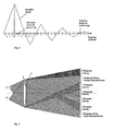
- the selected 1st diffraction order forms the reconstructed hologram 3 as a Fourier transform, it does not represent the actual three-dimensional scene 6. It serves only as a viewer window 5 through which the three-dimensional scene 6 can be viewed (see FIG. Fig. 2 ). Inside the light beam of the 1st diffraction order, the actual three-dimensional scene 6 is indicated in the form of a circle. The scene thus lies within the reconstruction cone, which is spanned by the hologram 3 and the observer window 5. The scene is created as a Fresnel transform of the hologram, while the viewer window is part of the Fourier transform.
- the Fig. 3 shows the holographic coding.
- the three-dimensional scene is built up of points. With the observer window 5 as the base and the selected point 7 in the scene 6 as a peak, a cone is projected extended through this point onto the hologram 3. The result is a projection area 8 in the video hologram 3, in which this point is holographically encoded.
- To calculate the phase values one can determine the path lengths from the considered point 7 to the cells of the hologram 3. With this reconstruction, the size of the observer window 5 is maintained in the periodicity interval.
- the considered point 7 were coded in the entire hologram 3, the reconstructed would be extended beyond the periodicity interval.
- the viewer zones from adjacent diffraction orders would overlap, with the viewer seeing a periodic continuation of the point 7 under consideration. Such a coded surface would appear washed out by multiple overlays in their contours.
- the intensity decrease is used to higher diffraction orders towards the suppression of crosstalk to other viewer window.
- the Fig. 4 schematically shows an intensity profile of the light on the diffraction orders, which is formed by the width of the openings in the CGH.
- the diffraction orders are plotted on the abscissa.
- the 1st diffraction order represents the observer window 5 for the left eye, that is to say the left observer window, through which the three-dimensional scene 6 can be viewed.
- the crosstalk in a viewer window for the right eye is suppressed by the drop in intensity to higher orders and additionally by the zero of the intensity distribution.
- the observer can also view the scene 6 of the hologram 3 with both eyes (see FIG. Fig. 5 ).
- the right viewer window 5 ' became the -1. Diffraction order selected to the light source 1 '.
- this intensity only speaks to the left eye with a very low value. He corresponds here to the -6. Diffraction order.
- the 1st diffraction order was chosen according to the position of the light source 1.
- the left viewing window 5 is formed.
- the hologram 3 is recoded each time the light sources 1 and 1 'are switched on.
- the two light sources 1 and 1 ' can simultaneously reconstruct the hologram 3 at the two observer windows 5 and 5'.
- the light sources 1 and 1 ' are tracked so that the two observer windows 5 and 5' remain localized on the eyes of the observer. This also applies to movements in the normal, ie perpendicular to the video hologram. Furthermore, several viewers can also view a three-dimensional scene by creating additional viewer windows by connecting additional light sources.
Description
- Die Erfindung betrifft eine Einrichtung zur Rekonstruktion einer dreidimensionalen Szene gemäß dem Oberbegriff des Anspruchs 1 und ein Verfahren zur Rekonstruktion einer dreidimensionalen Szene.
- Es sind Einrichtungen zur Rekonstruktion von Videohologrammen mit akustooptischen Modulatoren (AOM) bekannt (Stephen A. Benton, Joel S. Kollin: Three dimensional display system,
US 5,172,251 ). Diese akustooptischen Modulatoren wandeln elektrische Signale in optische Wellenfronten um, die dann durch Ablenkspiegel zu zweidimensionalen holografischen Flächen innerhalb eines Videoframes zusammengesetzt werden. Die Wellenfronten werden über weitere optische Elemente als eine für den Betrachter sichtbare Szene rekonstruiert. Die verwendeten optischen Mittel, wie Linsen und Ablenkelemente, haben die Ausdehnung der rekonstruierten Szenen und sind mit ihrer großen Bautiefe voluminös und schwer. Sie lassen sich kaum miniaturisieren und sind daher in ihrem Anwendungsbereich beschränkt. - Eine andere Möglichkeit, grosse Videohologramme zu erzeugen, bietet das sogenannte Tiling-Verfahren mit Computer Generierten Hologrammen (CGH). Nach diesem aus
WO 00/75698 A1 US 6,437,919 B1 bekannten Verfahren werden kleine CGHs mit kleinem Pitch über eine Abbildungsoptik zusammengesetzt. Dafür werden in einem ersten Schritt schnelle Matrizen mit kleinem Pitch (in der Regel EASLM: Electronisch Adressierbare Spatiale Licht-Modulatoren) mit der nötigen Information beschrieben, auf ein holografisch geeignetes Medium abgebildet und zu einem größeren Videohologramm zusammengesetzt. Das verwendete Medium ist in der Regel ein Optisch Adressierbarer Spatialer Licht-Modulator (OASLM). In einem zweiten Schritt wird das zusammengesetzte Videohologramm mit kohärentem Licht in Transmission oder Reflexion rekonstruiert. - Bei den beispielsweise aus
WO 01/95016 A1 - Eine Einrichtung zur Rekonstruktion einer dreidimensionalen Szene gemäß dem Oberbegriff des Anspruchs 1 ist beispielsweise aus der
US 5,889,599 bekannt. - Bei Fourierhologrammen findet bekanntlich die Rekonstruktion in eine Ebene als direkte oder inverse Fouriertransformierte des Hologramms statt. Diese Rekonstruierte setzt sich periodisch mit einem Periodizitätsintervall fort, dessen Ausdehnung umgekehrt proportional zum Pitch im Hologramm ist.
Wenn die Ausdehnung der Rekonstruierten des Fourierhologramms grösser als das Periodizitätsintervall ist, überlappen sich benachbarte Beugungsordnungen. Mit zunehmender Verringerung der Auflösung, also wachsendem Pitch der Öffnungen, werden die Ränder der Rekonstruierten durch Überlappung aus den höheren Beugungsordnungen zunehmend gestört. Die nutzbare Rekonstruktion wird dadurch in ihrer Ausdehnung mehr und mehr eingeschränkt.
Will man größere Periodizätsintervalle und damit also grössere Betrachterwinkel erzielen, nähert sich der erforderliche Pitch im Hologramm der Lichtwellenlänge. Um dann möglichst große Szenen darstellen zu können, müssen aber auch die CGH entsprechend groß sein. Beide Forderungen verlangen ein großes CGH mit sehr vielen Öffnungen, das in Form von Displays mit steuerbaren Öffnungen gegenwärtig nicht realisierbar ist (s.EP 0 992 163B1 ). CGH mit steuerbaren Öffnungen sind daher nur ein oder wenige Zoll gross, wobei die Pitches noch erheblich über 1 µm liegen. - Beide Parameter, Pitch und Hologrammgrösse, werden durch das sogenannte Space-Bandwith-Produkt (SBP) als Anzahl der Öffnungen im Hologramm beschrieben. Soll die Rekonstruktion von einem CGH mit steuerbaren Öffnungen mit 50 cm Breite so erfolgen, dass ein Betrachter die Szene im Abstand von 1 m innerhalb eines horizontalen Betrachterfensters von 50 cm sehen kann, beträgt das SPB in horizontaler Richtung etwa 0,5*106. Dem entsprechen im CGH 500.000 steuerbare Öffnungen mit einem Abstand von 1 µm. Bei einem Aspekt-Verhältnis von 4:3 ergeben sich in vertikaler Richtung entsprechend 375.000 Öffnungen. Das CGH enthält somit 3,75*1011 Öffnungen, wenn man drei Farbsubpixel berücksichtigt. Diese Zahl verdreifacht sich noch, wenn man bedenkt, dass im CGH mit steuerbaren Öffnungen meist nur Amplituden beeinflusst werden können. Die Phasenkodierung erfolgt dann über den sogenannten Detourphasen-Effekt, wofür mindestens drei äquidistante Öffnungen je Abtastpunkt erforderlich sind. SLM mit so vielen steuerbaren Öffnungen sind derzeit nicht bekannt.
- Die Hologrammwerte müssen aus den zu rekonstruierenden Szenen berechnet werden. Bei einer Farbtiefe von 1 Byte für jede der drei Grundfarben und einer Frame-Rate von 50 Hz benötigt ein CGH einen Informationsfluss von 50*1012 = 0,5*1014 Byte/s. Fouriertransformationen von Datenströmen dieser Grösse übersteigen die Leistung derzeit einsetzbarer Rechner bei weitem und schliessen eine Hologramm-Berechnung auf Basis lokaler Rechner aus. Aber auch eine Übertragung dieser Informationsmenge über Datennetze ist für den normalen Nutzer gegenwärtig nicht realisierbar.
- Um die umfangreichen Rechenvorgänge zu verringern, wird beispielsweise auch vorgeschlagen, das Hologramm nicht vollständig zu berechnen, sondern nur in den Teilen, die direkt vom Betrachter eingesehen werden können oder die sich ändern. In der oben schon genannten Patentschrift
WO 01/95016 A1 - Die Nachteile der bekannten Verfahren bestehen zusammengefasst darin, dass die Anordnungen mit akusto-optischen Modulatoren zu voluminös sind und nicht auf heutige aus der Flachbildschirmtechnik bekannte Abmessungen reduziert werden können, dass die Videohologramme nach dem Tiling-Verfahren zweistufige Verfahren mit grossem technologischen Aufwand sind, die sich schwerlich auf Desktop-Grösse reduzieren lassen und dass schließlich die Anordnungen auf der Basis von SLM mit steuerbaren Öffnungen zu klein sind, um grosse Szenen rekonstruieren zu können. Dazu fehlen momentan steuerbare grosse SLM mit extrem kleinen Pitches sowie die erforderlichen Rechenleistungen und die erforderliche hohe Bandbreite der Netzwerke.
- Der Erfindung liegt die Aufgabe zugrunde, die angeführten Nachteile zu umgehen und ausgedehnte Videodarstellungen von Hologrammen in Echtzeit und für grosse Betrachterwinkel zu ermöglichen.
- Diese Aufgabe wird erfindungsgemäß mit den im Patentanspruch 1 aufgeführten Merkmalen gelöst. Vorteilhafte Ausgestaltungen der Erfindung sind in den Patentansprüchen 2 bis 11 angegeben.
- Die Videohologramme und Einrichtungen zur Rekonstruktion von Videohologrammen mit steuerbaren Öffnungen sehen vor, dass in der Betrachterebene mindestens ein Betrachterfenster in einem Periodizitätsintervall als direkte oder inverse Fouriertransformierte des Videohologramms gebildet wird, durch das hindurch ein Betrachter eine dreidimensionale Szene als Rekonstruktion sehen kann. Die Ausdehnung des Betrachterfensters entspricht maximal dem Periodizitätsintervall in der Ebene der Fourier-Rücktransformation am Ort des Lichtquellenbildes. Das Betrachterfenster spannt zusammen mit dem Hologramm einen Kegelstumpf auf, der die gesamte dreidimensionale Szene als Fresnel-Transformierte des Videohologramms enthält.
Ein Betrachterfenster ist in Ausbildung der Erfindung in etwa auf ein Auge oder auf einen anderen geeigneten Bereich begrenzt und positioniert, wobei dem anderen Auge des Betrachters analog ein zweites Betrachterfenster zugeordnet wird. Das erfolgt dadurch, dass die betrachtete Lichtquelle entsprechend versetzt oder durch Zuschalten einer zweiten reellen oder virtuellen, hinreichend kohärenten Lichtquelle an einem anderen geeigneten Ort zu einem Lichtquellenpaar im optischen System ergänzt wird. Auf diese Weise wird die beidäugige Betrachtung der dreidimensionalen Szene durch zwei zugehörige Betrachterfenster ermöglicht. Dabei kann der Inhalt des Videohologramms synchron mit dem Zuschalten des zweiten Betrachterfensters entsprechend der Augenposition geändert, d.h. umkodiert werden. Bei mehreren Betrachtern können so durch Zuschalten weiterer Lichtquellen entsprechend viele Betrachterfenster erzeugt werden.
Für die Einrichtung zur Rekonstruktion eines Videohologramms besteht ein anderer wesentlicher Erfindungsgedanke darin, das optische System und das Videohologramm so anzuordnen, dass die höheren Beugungsordnungen des Videohologramms für das erste Betrachterfenster eine Nullstelle bzw. ein Intensitätsminimum am Ort des zweiten Betrachterfensters aufweisen. Damit wird ein Übersprechen eines Betrachterfensters für ein Auge auf das andere Auge eines Betrachters oder auf andere Betrachter verhindert. Der Intensitätsabfall des Lichts zu höheren Beugungsordnungen hin aufgrund der endlichen Breite der Öffnungen des Videohologramms oder/und der Minima des Intensitätsverlaufs wird so vorteilhaft ausgenutzt. Bei zum Beispiel rechteckigen Öffnungen entsteht als Intensitätsverlauf eine sinc2-Funktion, die schnell abfällt und eine mit grösser werdenden Abständen abnehmende sin2-Funktion darstellt.
Für das Videohologramm sind nur so viele Werte zu berechnen, wie das Display Öffnungen hat. Auf die gleiche Anzahl von Werten ist die Übertragung der Daten vom Computer oder vom Netz auf das Display als Hologramm beschränkt. Der Datenstrom unterscheidet sich daher praktisch nicht von dem heute schon durch die übliche Displaytechnik zu verarbeitenden Datenstrom. Das soll anhand eines Beispiels verdeutlicht werden.
Reduziert man das Betrachterfenster durch Wahl eines hinreichend grob auflösenden Displays beispielsweise von horizontal 50 cm und vertikal 37,5 cm auf 1 cm x 1 cm, so entspricht das einer Reduzierung der Anzahl der Öffnungen im Hologramm auf 1/1875. In gleicher Weise wird bei einem Transfer über ein Netzwerk die erforderliche Bandbreite reduziert. Bei den nach bekannten Verfahren hergestellten Videohologrammen mit erforderlichen 1012 Öffnungen reduzieren sich diese im Beispiel auf etwa 5*108 Pixel. Durch das verbleibende Betrachterfenster kann die Szene vollständig betrachtet werden. Diese Anforderungen an Pitch und Hologrammgrösse entsprechend dem Space-Bandwith-Produkt können heute verfügbare Displays bereits erfüllen. Damit können auf kostengünstige Weise grosse Echtzeit-Videohologramme auf Displays mit großem Pitch für einen großen Betrachterbereich realisiert werden.
Die Nachführung des Betrachterfensters (Tracking) wird durch mechanischen oder elektronischen Versatz der Lichtquellen, durch bewegliche Spiegel oder von auf andere geeignete Weise positionierbare Lichtquellen realisiert. Mit dem Verschieben der Lichtquellenbilder verschieben sich auch die Betrachterfenster. Bewegt sich der Betrachter, wird/werden die Lichtquelle/n so im Raum verschoben, dass die Betrachterfenster den Augen des Betrachters folgen. Dadurch wird gesichert, dass die Betrachter auch bei Bewegung die rekonstruierte dreidimensionale Szene sehen und andererseits ihre Bewegungsfreiheit nicht eingeschränkt ist. Für die Positionsdetektion der Betrachter sind verschiedene Systeme bekannt, die hier vorteilhaft einsetzbar sind, beispielsweise auf Magnetsensoren basierende. - Mit den erfindungsgemäßen Mitteln ist auch die farbige Rekonstruktion eines Videohologramms effektiv möglich. Dabei ist vorgesehen, dass die Rekonstruktion mit mindestens drei für die Grundfarben in Amplitude und/oder Phase steuerbaren Öffnungen je Zelle erfolgt, wobei die Kodierung für die Öffnungen für jede Grundfarbe separat vorgenommen wird. Eine andere Möglichkeit der farbigen Rekonstruktion eines Videohologramms besteht darin, wenigstens drei nacheinander ausgeführte Rekonstruktionen in den Grundfarben auf der Grundlage der erfindungsgemäßen Einrichtung durchzuführen.
- Mit der vorliegenden Erfindung können vorteilhafterweise holografische Darstellungen von ausgedehnten räumlichen Szenen mittels steuerbarer Displays, wie TFT-Flachdisplays, in Echtzeit und für grosse Betrachterwinkel erzeugt werden. Diese Videohologramme sind vorteilhafterweise im Fernseh-, Multimedia-, Spiele- und Konstruktionsbereich, in der Militär- und in der Medizintechnik und in anderen Bereichen von Wirtschaft und Gesellschaft anwendbar. Die dreidimensionalen Szenen können computergeneriert oder auf andere Weise erzeugt werden.
- Ein Ausführungsbeispiel der Erfindung ist in der
Figur 5 dargestellt und wird im folgenden näher beschrieben. - Es zeigen
- Fig. 1
- eine prinzipielle Darstellung eines Videohologramms und einer Einrichtung zur Rekonstruktion von Videohologrammen mit der Entstehung der Beugungsordnungen und der Lage eines Betrachterfensters,
- Fig. 2
- eine prinzipielle Darstellung einer Einrichtung zur Rekonstruktion von Videohologrammen mit einer dreidimensionalen Szene, die durch ein Betrachterfenster hindurch betrachtet werden kann,
- Fig. 3
- eine prinzipielle Darstellung einer Einrichtung zur Rekonstruktion von Videohologrammen mit der Kodierung der dreidimensionalen Szene in einem Teil des Videohologramms, so dass die Beugungsordnungen nicht überlappen,
- Fig. 4
- einen Intensitätsverlauf des Lichtes in der Betrachterebene in Abhängigkeit von den Beugungsordnungen und
- Fig. 5
- eine prinzipielle Darstellung einer erfindungsgemäßen Einrichtung zur Rekonstruktion von Videohologrammen mit der Lage der Betrachterfenster für beide Augen eines Betrachters hinsichtlich der Beugungsordnungen zur Vermeidung von Übersprechen.
- Eine Einrichtung zur Rekonstruktion von Videohologrammen besteht aus dem Videohologramm, einer hinreichend kohärenten reellen oder virtuellen punkt- oder linienförmigen Lichtquelle und aus einem optischen System. Das Videohologramm selbst setzt sich aus matrixförmig oder in anderer Weise regulär angeordneten Zellen zusammen, die mindestens eine in Amplitude und/oder Phase steuerbare Öffnung je Zelle enthalten. Das optische System zur Rekonstruktion des Videohologramms lässt sich in bekannter Weise z.B. einfach durch ein optisches Abbildungssystem, bestehend aus einem punkt- oder linienförmigen Laser und einer hinreichend kohärenten Lichtquelle realisieren.
- Die grundsätzliche Anordnung von Videohologramm und Rekonstruktion zeigt
Fig. 1 . In Lichtrichtung sind hintereinander eine Lichtquelle 1, eine Linse 2, ein Hologramm 3 und eine Betrachterebene 4 angeordnet. Der Betrachterebene 4 entspricht die Fourierebene der Rücktransformation des Videohologramms mit den Beugungsordnungen. - Die Lichtquelle 1 wird durch ein optisches System, repräsentiert durch die Linse 2, in die Betrachterebene 4 abgebildet. Setzt man ein Hologramm 3 ein, so wird es in der Betrachterebene 4 als Fourier-Rücktransformation dargestellt. Das Hologramm 3 mit periodischen Öffnungen erzeugt äquidistant fortgesetzte Beugungsordnungen in der Betrachterebene 4, wobei die holografische Kodierung, beispielsweise mittels des sogenannten Detourphasen-Effektes, in die höheren Beugungsordnungen erfolgt. Da die Intensität nach höheren Beugungsordnungen hin abnimmt, wird in der Regel die 1. oder die -1. Beugungsordnung als Betrachterfenster 5 gewählt. Wenn nicht ausdrücklich anders angegeben, wird zur Darlegung der Erfindung im weiteren von der 1. Beugungsordnung ausgegangen.
- Die Ausdehnung der Rekonstruktion wurde hier so gewählt, dass sie in ihrer Größe mit dem Periodizitätsintervall der 1. Beugungsordnung in der Betrachterebene 4 übereinstimmt. Somit schliessen sich höhere Beugungsordnungen ohne Lücke, aber auch ohne Überlappung aneinander an.
- Die ausgewählte 1. Beugungsordnung bildet zwar als Fouriertransformierte die Rekonstruierte des Hologramms 3, stellt aber nicht die eigentliche dreidimensionale Szene 6 dar. Sie dient nur als Betrachterfenster 5, durch das hindurch die dreidimensionale Szene 6 betrachtet werden kann (s.
Fig. 2 ). Im Inneren des Lichtbündels der 1. Beugungsordnung ist die eigentliche dreidimensionale Szene 6 in Form eines Kreises angedeutet. Die Szene liegt also innerhalb des Rekonstruktionskegels, der vom Hologramm 3 und dem Betrachterfenster 5 aufgespannt wird. Die Szene entsteht als Fresnel-Transformierte des Hologramms, während das Betrachterfenster ein Teil der Fourier-Transformierten ist. - Die
Fig. 3 zeigt dazu die holografische Kodierung. Die dreidimensionale Szene ist aus Punkten aufgebaut. Mit dem Betrachterfenster 5 als Basis und dem ausgewählten Punkt 7 in der Szene 6 als Spitze wird ein Kegel durch diesen Punkt hindurch verlängert auf das Hologramm 3 projiziert. Es entsteht ein Projektionsgebiet 8 im Videohologramm 3, in dem dieser Punkt holografisch kodiert wird. Zur Berechnung der Phasenwerte kann man die Weglängen vom betrachteten Punkt 7 zu den Zellen des Hologramms 3 bestimmen. Mit dieser Rekonstruktion wird die Grösse des Betrachterfensters 5 im Periodizitätsintervall eingehalten. Würde im Beispiel dagegen der betrachtete Punkt 7 im gesamten Hologramm 3 kodiert, wäre die Rekonstruierte über das Periodizitätsintervall hinaus ausgedehnt. Die Betrachterzonen aus benachbarten Beugungsordnungen würden sich überlappen, wobei der Betrachter eine periodische Fortsetzung des betrachteten Punktes 7 sehen würde. Eine so kodierte Oberfläche würde durch Mehrfachüberlagerungen in ihren Konturen verwaschen erscheinen. - Vorteilhafterweise wird der Intensitätsabfall zu höheren Beugungsordnungen hin zur Unterdrückung des Übersprechens auf andere Betrachterfenster genutzt. Die
Fig. 4 zeigt dazu schematisch einen Intensitätsverlauf des Lichts über die Beugungsordnungen, der durch die Breite der Öffnungen im CGH entsteht. Auf der Abszisse sind die Beugungsordnungen aufgetragen. Die 1. Beugungsordnung stellt das Betrachterfenster 5 für das linke Auge, also das linke Betrachterfenster, dar, durch das die dreidimensionale Szene 6 betrachtet werden kann. Das Übersprechen in ein Betrachterfenster für das rechte Auge wird durch den Abfall der Intensität zu höheren Ordnungen und zusätzlich noch durch die Nullstelle der Intensitätsverteilung unterdrückt. - Der Betrachter kann die Szene 6 des Hologramms 3 natürlich auch mit beiden Augen betrachten (s.
Fig. 5 ). Für das rechte Auge wurde als rechtes Betrachterfenster 5' die -1. Beugungsordnung zur Lichtquelle 1' gewählt. Wie aus der Zeichnung ersichtlich ist, spricht diese Intensität nur mit einem sehr geringen Wert auf das linke Auge über. Er entspricht hier der -6. Beugungsordnung.
Für das linke Auge wurde die 1. Beugungsordnung entsprechend der Lage der Lichtquelle 1 gewählt. Dort entsteht analog das linke Betrachtungsfenster 5. Erfindungsgemäss werden mit den zwei Lichtquellen 1 und 1' die entsprechenden dreidimensionalen Szenen 6 und 6' (hier nicht gezeigt) ortsfest bezüglich der Augen dargestellt. Dazu wird das Hologramm 3 beim Zuschalten der Lichtquellen 1 und 1' jeweils neu kodiert. Alternativ können die beiden Lichtquellen 1 und 1' gleichzeitig das Hologramm 3 an den beiden Betrachterfenstern 5 und 5' rekonstruieren. - Bewegt sich der Betrachter, werden die Lichtquellen 1 und 1' so nachgeführt, dass die beiden Betrachterfenster 5 und 5' auf den Augen des Betrachters lokalisiert bleiben. Dies gilt auch bei Bewegungen in der Normalen, also senkrecht zum Videohologramm.
Weiterhin können auch mehrere Betrachter eine dreidimensionale Szene betrachten, indem durch Zuschalten weiterer Lichtquellen zusätzliche Betrachterfenster entstehen.
Claims (12)
- Einrichtung zur Rekonstruktion einer dreidimensionalen Szene mit einem optischen System, enthaltend mindestens eine reelle oder virtuelle punkt- oder linienförmige, hinreichend kohärente Lichtquelle (1) und eine Linse (2), sowie mit einem steuerbaren Display (3) aus matrixförmig oder in anderer Weise regulär angeordneten Zellen mit mindestens einer in Amplitude und/oder Phase steuerbaren Öffnung je Zelle, wobei in das steuerbare Display (3) ein Videohologramm kodierbar ist, wobei die Linse (2) ein Bild der Lichtquelle (1) in einer Betrachterebene (4) erzeugt, wobei in der Betrachterebene (4) ein Betrachterfenster (5) innerhalb einer Beugungsordnung des steuerbaren Displays (3) und nicht größer als diese Beugungsordnung des steuerbaren Displays (3) lokalisierbar ist, durch welches hindurch eine Rekonstruktion der dreidimensionalen Szene (6) mit einem Auge eines Betrachters betrachtbar ist, dadurch gekennzeichnet, dass dem anderen Auge des Betrachters ein zweites Betrachterfenster (5') in der Betrachterebene (4) zugeordnet ist, indem die Lichtquelle (1) versetzt wird oder eine zweite reelle oder virtuelle, hinreichend kohärente Lichtquelle (1') an einem anderen geeigneten Ort zu einem Lichtquellenpaar (1, 1') im optischen System zugeschaltet wird.
- Einrichtung nach Patentanspruch 1, dadurch gekennzeichnet, dass das optische System und das steuerbare Display (3) so angeordnet sind, dass die höheren Beugungsordnungen des steuerbaren Displays (3) für das erste Betrachterfenster (5) eine Nullstelle bzw. ein Intensitätsminimum am Ort des zweiten Betrachterfensters (5') aufweisen.
- Einrichtung nach Patentanspruch 2, dadurch gekennzeichnet, dass synchron mit dem Zuschalten des zweiten Betrachterfensters (5') das steuerbare Display (3) für das zweite Auge umkodierbar ist.
- Einrichtung nach den Patentansprüchen 1 bis 3, dadurch gekennzeichnet, dass für mehrere Betrachter mehrere Lichtquellen zuschaltbar sind.
- Einrichtung nach einem der Patentansprüche 1 bis 4, dadurch gekennzeichnet, dass die Lichtquellen durch mechanischen oder elektronischen Versatz oder durch bewegliche Spiegel positionierbar sind.
- Einrichtung nach einem der Patentansprüche 1 bis 5, dadurch gekennzeichnet, dass die Information zur Bestimmung der Position der Lichtquellen von wenigstens einem Positionsgeber in Abhängigkeit von der Position des Betrachters oder der Betrachter geliefert wird.
- Einrichtung nach Patentanspruch 1, dadurch gekennzeichnet, dass die farbige Rekonstruktion eines Videohologrammes mit einem steuerbaren Display (3) aus matrixförmig oder regulär angeordneten Zellen mit mindestens drei für die Grundfarben in Amplitude und/oder Phase steuerbaren Öffnungen je Zelle erfolgt, wobei die Kodierung für die Öffnungen für jede Grundfarbe separat erfolgt.
- Einrichtung nach Patentanspruch 1, dadurch gekennzeichnet, dass die farbige Rekonstruktion durch wenigstens drei nacheinander ausgeführte Rekonstruktionen in den Grundfarben erfolgt.
- Einrichtung nach Patentanspruch 1, gekennzeichnet durch Mittel zum Nachführen der Positionen von Betrachterfenstern, welche auf die Augen des Betrachters lokalisiert sind, durch mechanisches oder elektronischen Verschieben der Lichtquellen (1, 1'), um Augenbewegungen des Betrachters zu folgen.
- Einrichtung nach Patentanspruch 1, dadurch gekennzeichnet, dass die dreidimensionale Szene (6) aus Punkten aufgebaut ist, für die das steuerbare Display (3) so kodiert ist, dass im steuerbaren Display (3) ein Projektionsgebiet (8) entsteht, in dem ein ausgewählter Punkt (7) der dreidimensionalen Szene (6) holographisch kodiert ist, und dass beim Rekonstruieren die Größe des Betrachterfensters (5) innerhalb der Beugungsordnung eingehalten wird, um mehrfach Überlagerungen durch benachbarte Beugungsordnungen zu vermeiden.
- Einrichtung nach Patentanspruch 10, dadurch gekennzeichnet, dass das Projektionsgebiet (8) eine Projektion vom Betrachterfenster (5) als Basis durch den Punkt (7) hindurch zum steuerbaren Display (3) ist.
- Verfahren zur Rekonstruktion einer dreidimensionalen Szene (6) unter Verwendung einer Einrichtung nach einem der Ansprüche 1 bis 11.
Priority Applications (2)
| Application Number | Priority Date | Filing Date | Title |
|---|---|---|---|
| EP09168963.8A EP2138910B1 (de) | 2002-11-13 | 2003-11-11 | Einrichtung zur Rekonstruktion von Videohologrammen |
| EP09168975.2A EP2138911B1 (de) | 2002-11-13 | 2003-11-11 | Einrichtung zur Rekonstruktion von Videohologrammen |
Applications Claiming Priority (3)
| Application Number | Priority Date | Filing Date | Title |
|---|---|---|---|
| DE10253292 | 2002-11-13 | ||
| DE10253292 | 2002-11-13 | ||
| PCT/DE2003/003791 WO2004044659A2 (de) | 2002-11-13 | 2003-11-11 | Videohologramm und einrichtung zur rekonstruktion von videohologrammen |
Related Child Applications (2)
| Application Number | Title | Priority Date | Filing Date |
|---|---|---|---|
| EP09168963.8A Division EP2138910B1 (de) | 2002-11-13 | 2003-11-11 | Einrichtung zur Rekonstruktion von Videohologrammen |
| EP09168975.2A Division EP2138911B1 (de) | 2002-11-13 | 2003-11-11 | Einrichtung zur Rekonstruktion von Videohologrammen |
Publications (2)
| Publication Number | Publication Date |
|---|---|
| EP1563346A2 EP1563346A2 (de) | 2005-08-17 |
| EP1563346B1 true EP1563346B1 (de) | 2009-09-02 |
Family
ID=32308559
Family Applications (3)
| Application Number | Title | Priority Date | Filing Date |
|---|---|---|---|
| EP09168975.2A Expired - Lifetime EP2138911B1 (de) | 2002-11-13 | 2003-11-11 | Einrichtung zur Rekonstruktion von Videohologrammen |
| EP03788795A Expired - Lifetime EP1563346B1 (de) | 2002-11-13 | 2003-11-11 | Einrichtung zur rekonstruktion von videohologrammen |
| EP09168963.8A Expired - Lifetime EP2138910B1 (de) | 2002-11-13 | 2003-11-11 | Einrichtung zur Rekonstruktion von Videohologrammen |
Family Applications Before (1)
| Application Number | Title | Priority Date | Filing Date |
|---|---|---|---|
| EP09168975.2A Expired - Lifetime EP2138911B1 (de) | 2002-11-13 | 2003-11-11 | Einrichtung zur Rekonstruktion von Videohologrammen |
Family Applications After (1)
| Application Number | Title | Priority Date | Filing Date |
|---|---|---|---|
| EP09168963.8A Expired - Lifetime EP2138910B1 (de) | 2002-11-13 | 2003-11-11 | Einrichtung zur Rekonstruktion von Videohologrammen |
Country Status (13)
| Country | Link |
|---|---|
| US (14) | US7839548B2 (de) |
| EP (3) | EP2138911B1 (de) |
| JP (5) | JP4473133B2 (de) |
| KR (2) | KR100915431B1 (de) |
| CN (3) | CN102520604B (de) |
| AT (1) | ATE441877T1 (de) |
| BR (1) | BR0316222A (de) |
| DE (2) | DE10353439B4 (de) |
| HK (2) | HK1087198A1 (de) |
| IL (1) | IL168538A (de) |
| MX (1) | MXPA05005229A (de) |
| RU (2) | RU2293365C2 (de) |
| WO (1) | WO2004044659A2 (de) |
Cited By (1)
| Publication number | Priority date | Publication date | Assignee | Title |
|---|---|---|---|---|
| WO2013110748A1 (de) | 2012-01-26 | 2013-08-01 | Seereal Technologies S.A. | Display mit betrachternachführung |
Families Citing this family (121)
| Publication number | Priority date | Publication date | Assignee | Title |
|---|---|---|---|---|
| GB9903032D0 (en) * | 1999-02-11 | 1999-03-31 | Symbian Ltd | Messaging architecture |
| BR0316222A (pt) * | 2002-11-13 | 2005-10-04 | Seereal Technologies Gmbh | Holograma de vìdeo e dispositivo para reconstruir hologramas de vìdeo |
| DE102004044111B4 (de) * | 2004-09-08 | 2015-05-07 | Seereal Technologies Gmbh | Verfahren und Vorrichtung zum Kodieren und Rekonstruieren von computergenerierten Videohologrammen |
| DE102004063838A1 (de) | 2004-12-23 | 2006-07-06 | Seereal Technologies Gmbh | Verfahren und Einrichtung zum Berechnen computer generierter Videohologramme |
| DE102005021155B3 (de) | 2005-04-29 | 2006-11-23 | Seereal Technologies Gmbh | Steuerbare Beleuchtungseinrichtung |
| RU2383913C2 (ru) * | 2005-05-06 | 2010-03-10 | Сириал Текнолоджиз Гмбх | Устройство для голографической реконструкции трехмерных сцен |
| US8049941B2 (en) | 2005-12-22 | 2011-11-01 | Seereal Technologies S.A. | Method for the compensation of an inhomogeneous brightness perception in holographically reconstructed scenes |
| CN101346674B (zh) | 2005-12-22 | 2012-06-27 | 视瑞尔技术公司 | 全息再现场景中不均匀亮度感知补偿的方法 |
| DE102006003741B4 (de) * | 2006-01-18 | 2009-08-27 | Seereal Technologies S.A. | Verfahren zum Kodieren eines computergenerierten Hologramms |
| DE102006004301A1 (de) * | 2006-01-20 | 2007-08-02 | Seereal Technologies S.A. | Holographische Projektionsvorrichtung zur Vergrößerung eines Rekonstruktionsbereichs |
| DE102006018689A1 (de) * | 2006-04-13 | 2007-10-25 | Seereal Technologies S.A. | Verfahren zum Rendern und Generieren computergenerierter Videohologramme in Echtzeit |
| DE102006024356B4 (de) | 2006-05-19 | 2016-09-29 | Seereal Technologies S.A. | Holographische Projektionsvorrichtung zur Rekonstruktion von Szenen und Verfahren zur holographischen Rekonstruktion |
| WO2008025842A1 (de) | 2006-09-01 | 2008-03-06 | Seereal Technologies S.A. | Schnittstelle und schaltungsanordnung insbesondere für holografische kodiereinheiten oder holografische wiedergabeeinrichtungen |
| DE102006042324B4 (de) * | 2006-09-01 | 2014-06-18 | Seereal Technologies S.A. | Verfahren zum Generieren computer-generierter Videohologramme in Echtzeit mittels Teilhologrammen |
| CN101512445B (zh) | 2006-09-01 | 2013-07-17 | 视瑞尔技术公司 | 借助亚全息图实时生成视频全息图的方法 |
| JP5266223B2 (ja) | 2006-09-01 | 2013-08-21 | シーリアル テクノロジーズ ソシエテ アノニム | 伝播を使用して計算機ビデオホログラムをリアルタイムに生成する方法 |
| DE102006041637B4 (de) * | 2006-09-05 | 2010-11-25 | Seereal Technologies S.A. | Wiedergabevorrichtung und Verfahren zum Nachführen eines Betrachterfensters |
| DE102006042467A1 (de) * | 2006-09-09 | 2008-03-27 | Seereal Technologies S.A. | Verfahren und Vorrichtung zur Kodierung von computergenerierten Hologrammen in pixelierten Lichtmodulatoren |
| DE102006043297B4 (de) * | 2006-09-14 | 2010-12-09 | Seereal Technologies S.A. | Wiedergabevorrichtung und Verfahren mit Mitteln zum Nachführen eines Betrachterfensters |
| DE102007024236A1 (de) * | 2007-05-21 | 2008-11-27 | Seereal Technologies S.A. | Holographisches Rekonstruktionssystem mit einer Anordnung von steuerbaren Mikroprismen |
| US8416479B2 (en) * | 2006-10-26 | 2013-04-09 | Seereal Technologies S.A. | Compact holographic display device |
| US8958137B2 (en) * | 2006-10-26 | 2015-02-17 | Seereal Technologies S.A. | Holographic display device with 2D encoding |
| GB0709379D0 (en) * | 2007-05-16 | 2007-06-27 | Seereal Technologies Sa | Smart display extended |
| DE102007024237B4 (de) | 2007-05-21 | 2009-01-29 | Seereal Technologies S.A. | Holographisches Rekonstruktionssystem mit einer optischen Wellennachführung |
| TWI454742B (zh) * | 2006-10-26 | 2014-10-01 | Seereal Technologies Sa | 全像顯示裝置(四) |
| TWI422999B (zh) * | 2006-10-26 | 2014-01-11 | Seereal Technologies Sa | 全像顯示裝置、其製造方法及產生全像重建的方法 |
| DE102006062376B4 (de) | 2006-12-19 | 2018-03-22 | Seereal Technologies S.A. | Verfahren und Wiedergabeeinrichtung zum Reduzieren von Speckle |
| DE102006062377B4 (de) | 2006-12-19 | 2018-03-22 | Seereal Technologies S.A. | Verfahren und holographische Wiedergabeeinrichtung zum Reduzieren von Speckle |
| DE102006062413A1 (de) * | 2006-12-21 | 2008-06-26 | Seereal Technologies S.A. | Holographische Projektionsvorrichtung zur Vergrößerung eines Sichtbarkeitsbereichs |
| DE102007005822A1 (de) | 2007-01-31 | 2008-08-07 | Seereal Technologies S.A. | Holographisches Rekonstruktionssystem mit optischer Wellennachführung |
| DE102007005823A1 (de) | 2007-01-31 | 2008-08-07 | Seereal Technologies S.A. | Optische Wellenfrontkorrektur für ein holographisches Projektionssystem |
| DE102007011561B4 (de) * | 2007-03-02 | 2016-03-17 | Seereal Technologies S.A. | Einrichtung zur Korrektur der Wellenlängenabhängigkeit in beugungsbasierten optischen Systemen |
| DE102007011560A1 (de) | 2007-03-02 | 2008-09-04 | Seereal Technologies S.A. | Vorrichtung zur Minimierung der verbeugungsbedingten Dispersion in Lichtmodulatoren |
| DE102007018266A1 (de) | 2007-04-10 | 2008-10-16 | Seereal Technologies S.A. | Holographisches Projektionssystem mit einer optischen Wellennachführung und Mitteln zum Korrigieren der holographischen Rekonstruktion |
| DE102007023740B4 (de) | 2007-05-16 | 2009-04-09 | Seereal Technologies S.A. | Verfahren zur Generierung von Videohologrammen für eine holographische Wiedergabeeinrichtung mit wahlfreier Adressierung |
| DE102007023739B4 (de) * | 2007-05-16 | 2018-01-04 | Seereal Technologies S.A. | Verfahren zum Rendern und Generieren von Farbvideohologrammen in Echtzeit und holographische Wiedergabeeinrichtung |
| DE102007023738A1 (de) * | 2007-05-16 | 2009-01-08 | Seereal Technologies S.A. | Verfahren und Einrichtung zum Rekonstruieren einer dreidimensionalen Szene in einem holographischen Display |
| US9581965B2 (en) | 2007-05-16 | 2017-02-28 | Seereal Technologies S.A. | Analytic method for computing video holograms in real time |
| US8218211B2 (en) | 2007-05-16 | 2012-07-10 | Seereal Technologies S.A. | Holographic display with a variable beam deflection |
| DE102007023785B4 (de) | 2007-05-16 | 2014-06-18 | Seereal Technologies S.A. | Analytisches Verfahren zu Berechnung von Videohologrammen in Echtzeit und holographische Wiedergabeeinrichtung |
| DE102007023737B4 (de) | 2007-05-16 | 2009-01-02 | Seereal Technologies S.A. | Verfahren zum Generieren von Videohologrammen in Echtzeit zur Erweiterung einer 3D-Rendering-Graphikpipeline |
| GB0718636D0 (en) | 2007-05-16 | 2007-11-07 | Seereal Technologies Sa | Holograms |
| DE102007025069B4 (de) | 2007-05-21 | 2018-05-24 | Seereal Technologies S.A. | Holographisches Rekonstruktionssystem |
| DE102007024235B4 (de) | 2007-05-21 | 2009-04-30 | Seereal Technologies S.A. | Holografisches Rekonstruktionssystem sowie -verfahren mit erweitertem Sichtbarkeitsbereich |
| DE102007028371B4 (de) | 2007-06-13 | 2012-05-16 | Seereal Technologies S.A. | Einrichtung zur Lichtmodulation |
| DE102007036127A1 (de) * | 2007-07-27 | 2009-01-29 | Seereal Technologies S.A. | Holographische Rekonstruktionseinrichtung |
| GB0716829D0 (en) * | 2007-08-31 | 2007-10-10 | Seereal Technologies Sa | Holographic display |
| DE102007045332B4 (de) | 2007-09-17 | 2019-01-17 | Seereal Technologies S.A. | Holographisches Display zum Rekonstruieren einer Szene |
| WO2009050294A2 (en) * | 2007-10-19 | 2009-04-23 | Seereal Technologies S.A. | Light modulating device |
| GB0720484D0 (en) * | 2007-10-19 | 2007-11-28 | Seereal Technologies Sa | Cells |
| DE102007051521A1 (de) | 2007-10-19 | 2009-04-23 | Seereal Technologies S.A. | Dynamische Wellenformereinheit |
| GB2454246B (en) | 2007-11-02 | 2010-03-10 | Light Blue Optics Ltd | Holographic image display systems |
| DE102008000116A1 (de) | 2008-01-21 | 2009-07-30 | Seereal Technologies S.A. | Beleuchtungseinheit für ein holographisches Rekonstruktionssystem |
| MD3896G2 (ro) * | 2008-01-25 | 2009-12-31 | Государственный Университет Молд0 | Dispozitiv pentru reconstrucţia hologramelor multiplexe |
| DE102008000589B4 (de) | 2008-03-11 | 2018-02-01 | Seereal Technologies S.A. | Verfahren zur Kodierung von computergenerierten Hologrammen in pixelierten Lichtmodulatoren |
| DE102008002692B4 (de) * | 2008-06-26 | 2019-02-21 | Seereal Technologies S.A. | Displayeinrichtung zur dreidimensionalen holographischen oder stereoskopischen Darstellung räumlicher Objekte und Verfahren zum Ermitteln einer Apodisationsfunktion für eine Apodisationsmaske |
| DE102008040581B4 (de) * | 2008-07-21 | 2017-06-01 | Seereal Technologies S.A. | Steuerbare Lichtmodulationseinrichtung |
| USD666663S1 (en) | 2008-10-20 | 2012-09-04 | X6D Limited | 3D glasses |
| USRE45394E1 (en) | 2008-10-20 | 2015-03-03 | X6D Limited | 3D glasses |
| USD624952S1 (en) | 2008-10-20 | 2010-10-05 | X6D Ltd. | 3D glasses |
| USD603445S1 (en) | 2009-03-13 | 2009-11-03 | X6D Limited | 3D glasses |
| US8542326B2 (en) | 2008-11-17 | 2013-09-24 | X6D Limited | 3D shutter glasses for use with LCD displays |
| CA2684513A1 (en) * | 2008-11-17 | 2010-05-17 | X6D Limited | Improved performance 3d glasses |
| DE102008054438A1 (de) | 2008-12-09 | 2010-06-24 | Seereal Technologies S.A. | Optisches Bauteil zum Ablenken von das optische Bauteil durchlaufende Lichtstrahlen |
| USD646451S1 (en) | 2009-03-30 | 2011-10-04 | X6D Limited | Cart for 3D glasses |
| US8927801B2 (en) | 2009-04-13 | 2015-01-06 | The Procter & Gamble Company | Absorbent articles comprising wetness indicators |
| USD650956S1 (en) | 2009-05-13 | 2011-12-20 | X6D Limited | Cart for 3D glasses |
| USD672804S1 (en) | 2009-05-13 | 2012-12-18 | X6D Limited | 3D glasses |
| USD692941S1 (en) | 2009-11-16 | 2013-11-05 | X6D Limited | 3D glasses |
| USD669522S1 (en) | 2010-08-27 | 2012-10-23 | X6D Limited | 3D glasses |
| USD671590S1 (en) | 2010-09-10 | 2012-11-27 | X6D Limited | 3D glasses |
| USD662965S1 (en) | 2010-02-04 | 2012-07-03 | X6D Limited | 3D glasses |
| KR101929836B1 (ko) | 2010-04-01 | 2018-12-18 | 시리얼 테크놀로지즈 에스.에이. | 홀로그래픽 시스템에서 투명 물체를 포함한 3차원 장면을 인코딩하는 방법 및 장치 |
| KR102094528B1 (ko) | 2010-07-06 | 2020-03-31 | 시리얼 테크놀로지즈 에스.에이. | 홀로그래픽 또는 입체 디스플레이를 위한 빔 확장 및 각종 콜리메이터 |
| USD664183S1 (en) | 2010-08-27 | 2012-07-24 | X6D Limited | 3D glasses |
| KR101670927B1 (ko) * | 2010-11-05 | 2016-11-01 | 삼성전자주식회사 | 디스플레이 장치 및 방법 |
| US8913149B1 (en) | 2010-11-30 | 2014-12-16 | Integrity Applications Incorporated | Apparatus and techniques for enhanced resolution imaging |
| DE102011005154B4 (de) | 2010-12-22 | 2022-03-31 | Seereal Technologies S.A. | Lichtmodulationsvorrichtung für ein holographisches oder ein autostereoskopisches Display |
| WO2012085045A1 (de) | 2010-12-22 | 2012-06-28 | Seereal Technologies S.A. | Kombinierte lichtmodulationsvorrichtung zur benutzernachführung |
| DE102011053037A1 (de) | 2011-08-26 | 2013-02-28 | Seereal Technologies S.A. | Beleuchtungsvorrichtung |
| KR101507202B1 (ko) * | 2011-11-16 | 2015-04-08 | 엘지디스플레이 주식회사 | 투과형 액정표시패널을 이용한 공간 광 변조 패널 및 이를 이용한 입체 영상 표시장치 |
| DE102011056006B4 (de) | 2011-12-01 | 2016-03-10 | Seereal Technologies S.A. | Verfahren zur Kodierung eines Hologramms in einer Lichtmodulationseinrichtung |
| KR101841624B1 (ko) * | 2012-01-25 | 2018-03-26 | 삼성전자주식회사 | 고속으로 3d 홀로그램을 생성하는 방법 및 장치 |
| US9581966B1 (en) | 2012-02-15 | 2017-02-28 | Integrity Applications Incorporated | Systems and methodologies related to 3-D imaging and viewing |
| US9934614B2 (en) | 2012-05-31 | 2018-04-03 | Microsoft Technology Licensing, Llc | Fixed size augmented reality objects |
| US9354606B1 (en) | 2012-07-31 | 2016-05-31 | Integrity Applications Incorporated | Systems and methodologies related to generating projectable data for 3-D viewing |
| USD711959S1 (en) | 2012-08-10 | 2014-08-26 | X6D Limited | Glasses for amblyopia treatment |
| US9219905B1 (en) | 2012-08-31 | 2015-12-22 | Integrity Applications Incorporated | Systems and methodologies related to formatting data for 3-D viewing |
| JP6013612B2 (ja) | 2012-09-26 | 2016-10-25 | ザ プロクター アンド ギャンブル カンパニー | 界面活性剤を有する液体活性化処方物 |
| AU2013237745A1 (en) | 2012-10-09 | 2014-04-24 | Aristocrat Technologies Australia Pty Limited | A gaming system and a method of gaming |
| CN103186090B (zh) * | 2013-03-14 | 2015-08-26 | 北京工业大学 | 数字全息成像在线重构显示系统及方法 |
| US9310769B2 (en) | 2013-03-28 | 2016-04-12 | Disney Enterprises, Inc. | Coarse integral holographic display |
| CN105264443B (zh) | 2013-06-06 | 2019-05-31 | 视瑞尔技术公司 | 用于计算全息图的数据的装置和方法 |
| FR3015743A1 (fr) * | 2013-12-23 | 2015-06-26 | Orange | Procede de traitement d'une sequence d'images holographiques, dispositifs, signaux, dispositifs et programme d'ordinateur associes |
| KR102208960B1 (ko) | 2014-04-09 | 2021-01-28 | 삼성전자주식회사 | 홀로그래픽 디스플레이 |
| US9473764B2 (en) | 2014-06-27 | 2016-10-18 | Microsoft Technology Licensing, Llc | Stereoscopic image display |
| KR20160027384A (ko) * | 2014-08-29 | 2016-03-10 | 전자부품연구원 | 투명-디스플레이와 홀로그램을 이용한 전시 장치 |
| DE102015101203B4 (de) | 2015-01-28 | 2021-06-17 | Seereal Technologies S.A. | Lichtmodulationsvorrichtung und holographische Anzeigevorrichtung |
| KR101800929B1 (ko) | 2015-01-29 | 2017-11-23 | 한국전자통신연구원 | 홀로그래픽 디스플레이 왜곡 보정 방법 및 장치 |
| KR102384223B1 (ko) | 2015-02-26 | 2022-04-07 | 삼성전자주식회사 | 3차원 영상 표시용 광 변조 신호 형성 방법, 3차원 영상 표시 방법 및 장치 |
| CN107533225B (zh) * | 2015-03-04 | 2020-07-14 | 脸谱科技有限责任公司 | 用于虚拟现实系统的稀疏投影 |
| DE102015205873A1 (de) | 2015-04-01 | 2016-10-06 | Seereal Technologies S.A. | Verfahren zur Berechnung von Hologrammen zur holographischen Rekonstruktion von zweidimensionalen und/oder dreidimensionalen Szenen |
| CN105223796B (zh) * | 2015-09-08 | 2018-09-11 | 北京邮电大学 | 基于近眼显示设备的全息图计算方法及装置 |
| DE112016006094T5 (de) | 2015-12-28 | 2018-12-06 | Seereal Technologies S.A. | Anzeigevorrichtung und Verfahren zum Optimieren der Bildqualität |
| US11300924B2 (en) | 2016-03-02 | 2022-04-12 | Seereal Technologies S.A. | Illumination device |
| WO2017198713A2 (de) * | 2016-05-18 | 2017-11-23 | Seereal Technologies S.A. | Verfahren zur erzeugung von hologrammen |
| CN108020977A (zh) * | 2016-10-28 | 2018-05-11 | 京东方科技集团股份有限公司 | 显示装置及其显示方法 |
| RU2650086C1 (ru) | 2016-12-22 | 2018-04-06 | Самсунг Электроникс Ко., Лтд. | Устройство отображения голографических изображений и способ функционирования блока управления, содержащегося в нем |
| US10969740B2 (en) | 2017-06-27 | 2021-04-06 | Nvidia Corporation | System and method for near-eye light field rendering for wide field of view interactive three-dimensional computer graphics |
| CN109581850B (zh) * | 2017-09-29 | 2021-03-05 | 京东方科技集团股份有限公司 | 全息显示方法和全息显示装置 |
| DE112018006228A5 (de) | 2017-12-07 | 2020-09-03 | Seereal Technologies S.A. | Head-up-display |
| CN108305320B (zh) * | 2018-02-09 | 2021-06-04 | 重庆大学 | 用于提高大视野全息成像质量的自适应滑动窗重建方法 |
| WO2020018878A1 (en) | 2018-07-20 | 2020-01-23 | Flex-N-Gate Advanced Product Development, Llc | Floating image generation |
| US10753579B2 (en) | 2018-07-20 | 2020-08-25 | Flex-N-Gate Advanced Product Development, Llc | Animated 3D image multiplier |
| CN112888998A (zh) | 2018-08-16 | 2021-06-01 | 视瑞尔技术公司 | 光调制装置 |
| US11454928B2 (en) * | 2018-11-06 | 2022-09-27 | Samsung Electronics Co., Ltd. | Holographic display apparatus and method for providing expanded viewing window |
| KR20230050404A (ko) | 2020-08-10 | 2023-04-14 | 시리얼 테크놀로지즈 에스.에이. | 홀로그램 데이터 계산을 위한 장치 및 방법 |
| KR102510926B1 (ko) * | 2020-10-14 | 2023-03-16 | 울산과학기술원 | 디더링 마스크에 기반한 홀로그램 색상 지정 시스템 및 홀로그램 색상 지정 방법 |
| US11798370B2 (en) | 2020-10-26 | 2023-10-24 | Lnw Gaming, Inc. | Gaming machine and method with symbol array alteration |
| US11907435B1 (en) | 2021-08-02 | 2024-02-20 | Omar Kevin Ubilla | Transformable apparatus with retractable display |
| WO2024058438A1 (ko) * | 2022-09-15 | 2024-03-21 | 삼성전자 주식회사 | 홀로그램 영상을 제공하는 전자 장치 및 전자 장치의 동작 방법 |
Citations (1)
| Publication number | Priority date | Publication date | Assignee | Title |
|---|---|---|---|---|
| US5889599A (en) * | 1996-02-29 | 1999-03-30 | Hamamatsu Photonics K.K. | Holography imaging apparatus holography display apparatus holography imaging method and holography display method |
Family Cites Families (111)
| Publication number | Priority date | Publication date | Assignee | Title |
|---|---|---|---|---|
| US4028323A (en) * | 1968-02-19 | 1977-06-07 | Ciba-Geigy Ag | Process for making azo compounds by coupling with nitrosated heterocyclic primary amines |
| US3635726A (en) * | 1968-09-20 | 1972-01-18 | Griffith Laboratories | Method of producing soy protein concentrates |
| US3966982A (en) * | 1973-06-18 | 1976-06-29 | Dravo Corporation | Process and apparatus for treating oleaginous seed material |
| US3957353A (en) * | 1974-03-08 | 1976-05-18 | The Board Of Trustees Of The Leland Stanford University | Multiemulsion transparency providing separate phase and amplitude control |
| US3897574A (en) * | 1974-03-21 | 1975-07-29 | Central Soya Co | Purification of ethanol extractant in soy protein concentrate process |
| US4188399A (en) * | 1974-12-23 | 1980-02-12 | Miles Laboratories, Inc. | Process for preparing a heat coagulable viscous protein |
| CA1066329A (en) * | 1976-03-16 | 1979-11-13 | Edward J. Falk | Tandem brake master cylinder |
| US4285862A (en) * | 1976-09-30 | 1981-08-25 | General Foods, Limited | Protein isolate product |
| US4072670A (en) * | 1976-10-26 | 1978-02-07 | Mead Johnson & Company | Low phytate isoelectric precipitated soy protein isolate |
| US4091120A (en) * | 1976-11-15 | 1978-05-23 | Mead Johnson & Company | Liquid dietary product containing soy protein membrane isolate |
| US4151828A (en) * | 1977-06-28 | 1979-05-01 | Solarpower, Inc. | Solar energy collection tube |
| US4321280A (en) * | 1977-12-01 | 1982-03-23 | General Foods Corporation | Textured oil seed protein products |
| US4284656A (en) * | 1979-12-14 | 1981-08-18 | Hwa Stephen C P | Novel protein curd product and process of preparation |
| US4435438A (en) * | 1980-12-29 | 1984-03-06 | A. E. Staley Manufacturing Company | Soy isolate suitable for use in imitation cheese |
| US4346122A (en) * | 1980-12-29 | 1982-08-24 | A. E. Staley Manufacturing Company | Low-viscosity, high-NSI, heat-gelling soy isolates |
| US4368151A (en) * | 1981-08-10 | 1983-01-11 | A. E. Staley Manufacturing Company | 7S And 11S vegetable protein fractionation and isolation |
| US4460613A (en) * | 1982-11-01 | 1984-07-17 | Ralston Purina Company | Basal material for the preparation of tofu |
| US4530788A (en) * | 1982-12-03 | 1985-07-23 | Stauffer Chemical Company | Oil seed proteins evidencing improved functionality |
| US4500454A (en) * | 1982-12-03 | 1985-02-19 | Stauffer Chemical Company | Vegetable protein evidencing improved solution viscosity |
| US4493854A (en) * | 1983-09-20 | 1985-01-15 | The United States Of America As Represented By The Secretary Of Agriculture | Production of defatted soybean products by supercritical fluid extraction |
| US5290959A (en) * | 1985-09-10 | 1994-03-01 | Vitamins, Inc. | Mass separation of materials |
| US5086166A (en) * | 1987-02-13 | 1992-02-04 | The Texas A&M University System | Protein foods and food ingredients and processes for producing them from defatted and undefatted oilseeds |
| US5097017A (en) * | 1989-12-20 | 1992-03-17 | Central Soya Company, Inc. | Process for making soy protein concentrate |
| US5172251A (en) | 1990-04-12 | 1992-12-15 | Massachusetts Institute Of Technology | Three dimensional display system |
| US5191449A (en) * | 1992-02-03 | 1993-03-02 | Cfc Applied Holographics | Animated holographic stereogram display |
| JPH0627864A (ja) * | 1992-07-10 | 1994-02-04 | Fujitsu Ltd | 計算機ホログラムの作成方法及び装置 |
| JPH0635391A (ja) * | 1992-07-20 | 1994-02-10 | Fujitsu Ltd | 立体表示装置 |
| JPH07261125A (ja) * | 1994-03-24 | 1995-10-13 | Olympus Optical Co Ltd | 投影型画像表示装置 |
| US5798964A (en) * | 1994-08-29 | 1998-08-25 | Toshiba Corporation | FRAM, FRAM card, and card system using the same |
| JP2765489B2 (ja) * | 1994-09-30 | 1998-06-18 | 不二製油株式会社 | 大豆たん白及びその製造法 |
| JP2989115B2 (ja) * | 1995-03-27 | 1999-12-13 | 浜松ホトニクス株式会社 | 立体表示方法および立体表示装置 |
| CA2146811C (en) * | 1995-04-11 | 2003-07-01 | David Michael Moore Dean | Method and apparatus for presenting stereoscopic images |
| US5936069A (en) * | 1995-12-06 | 1999-08-10 | Iowa State University Research Foundation | Process for producing improved soy protein concentrate from genetically-modified soybeans |
| ES2120878B1 (es) * | 1996-01-05 | 1999-06-01 | Alejo Trevijano Jose Javier | Sistema estereoscopico electronico. |
| BR9708545A (pt) * | 1996-04-09 | 1999-08-03 | Du Pont | Produto de proteína de soja método para a fabricação de um produto de proteína de soja produto substituinte do leite formulação para crianças pó ou líquido de bebida nutritivo pasta de queijo produto de presunto bologna produto de iogurte e sobremesa congelada |
| US6108440A (en) * | 1996-06-28 | 2000-08-22 | Sony Corporation | Image data converting method |
| JP3546618B2 (ja) * | 1996-12-19 | 2004-07-28 | 不二製油株式会社 | 大豆蛋白の製造法 |
| US6171640B1 (en) * | 1997-04-04 | 2001-01-09 | Monsanto Company | High beta-conglycinin products and their use |
| JP3798511B2 (ja) * | 1997-06-11 | 2006-07-19 | 浜松ホトニクス株式会社 | 計算機ホログラム表示装置 |
| GB9713658D0 (en) * | 1997-06-28 | 1997-09-03 | Travis Adrian R L | View-sequential holographic display |
| GB2330471A (en) | 1997-10-15 | 1999-04-21 | Secr Defence | Production of moving images for holography |
| US6330088B1 (en) | 1998-02-27 | 2001-12-11 | Zebra Imaging, Inc. | Method and apparatus for recording one-step, full-color, full-parallax, holographic stereograms |
| US6710920B1 (en) * | 1998-03-27 | 2004-03-23 | Sanyo Electric Co., Ltd | Stereoscopic display |
| DE19825192A1 (de) * | 1998-06-05 | 1999-12-16 | Joerg Gutjahr | Projektionsschirm |
| EP1105779A1 (de) | 1998-07-10 | 2001-06-13 | Digilens Inc. | Auf einem rekonfigurierbaren holographischen optischen system basierendes projektionssystem |
| JP2000059822A (ja) * | 1998-08-06 | 2000-02-25 | Toshiba Corp | 立体映像表示装置 |
| JP4026242B2 (ja) * | 1998-08-19 | 2007-12-26 | 松下電器産業株式会社 | 光学式3次元動画表示装置 |
| JP3505404B2 (ja) * | 1998-10-16 | 2004-03-08 | 理想科学工業株式会社 | ホログラムパターン決定装置、その決定方法及び記録媒体 |
| US6844458B2 (en) * | 1998-11-20 | 2005-01-18 | Ip Holdings, L.L.C. | Vegetable oil refining |
| EP1008919A1 (de) * | 1998-12-09 | 2000-06-14 | Communauté Européenne (CE) | Computergestütztes Verfahren und Vorrichtung zur Wiedergabe von dreidimensionalen Bildern |
| GB2350962A (en) | 1999-06-09 | 2000-12-13 | Secr Defence Brit | Holographic displays |
| US6335043B1 (en) * | 1999-08-03 | 2002-01-01 | Haokui Jiang | Method for extracting soybean proteins using an enzyme |
| US6665100B1 (en) * | 1999-08-10 | 2003-12-16 | Zebra Imaging, Inc. | Autostereoscopic three dimensional display using holographic projection |
| US6677327B1 (en) * | 1999-11-24 | 2004-01-13 | Archer-Daniels-Midland Company | Phytosterol and phytostanol compositions |
| IL134701A0 (en) * | 2000-02-23 | 2001-04-30 | J P M E D Ltd | Homogeneous solid matrix containing vegetable proteins |
| DE10008710C2 (de) * | 2000-02-24 | 2002-01-10 | Loh Optikmaschinen Ag | Vorrichtung zum zentrierenden Spannen von optischen Linsen für deren Randbearbeitung |
| GB2363273A (en) * | 2000-06-09 | 2001-12-12 | Secr Defence | Computation time reduction for three dimensional displays |
| WO2002013633A1 (en) * | 2000-08-11 | 2002-02-21 | Food & Packaging Centre Management Limited | Oil seed processing |
| IL154393A (en) * | 2000-08-18 | 2005-12-18 | Central Soya Co | Soy protein product and process for its manufacture |
| CN2439045Y (zh) * | 2000-08-31 | 2001-07-11 | 深圳市泛彩溢实业有限公司 | 全息液晶显示器 |
| CN1202732C (zh) * | 2000-09-29 | 2005-05-25 | 不二制油株式会社 | 生产大豆蛋白的方法 |
| GB0027103D0 (en) * | 2000-11-07 | 2000-12-20 | Secr Defence | Improved 3D display |
| JP2002149045A (ja) * | 2000-11-15 | 2002-05-22 | Victor Co Of Japan Ltd | ホログラム記録媒体 |
| US6630195B1 (en) * | 2000-11-21 | 2003-10-07 | Cargill, Incorporated | Process for producing oilseed protein products |
| US20040170743A1 (en) * | 2000-11-30 | 2004-09-02 | Kraft Foods Holdings, Inc. | Method of deflavoring soy-derived materials confectionary type products |
| US6787173B2 (en) * | 2000-11-30 | 2004-09-07 | Kraft Foods Holdings, Inc. | Method of deflavoring soy-derived materials |
| US20040161513A1 (en) * | 2000-11-30 | 2004-08-19 | Kraft Foods Holdings, Inc. | Method of preparation of high quality soy-containing meat and meat analog products |
| US7037547B2 (en) * | 2000-11-30 | 2006-05-02 | Kraft Foods Holdings, Inc. | Method of deflavoring soy-derived materials for use in beverages |
| US20040161512A1 (en) * | 2000-11-30 | 2004-08-19 | Kraft Foods Holdings, Inc. | Method of deflavoring soy-derived materials for use in dough-based and baked products |
| US7045163B2 (en) * | 2000-11-30 | 2006-05-16 | Kraft Foods Holdings, Inc. | Method of deflavoring soy-derived materials |
| US7175869B2 (en) * | 2000-11-30 | 2007-02-13 | Kraft Foods Holdings, Inc. | Method of deflavoring soy-derived materials using electrodialysis |
| US6576253B2 (en) * | 2000-12-05 | 2003-06-10 | Pbm Pharmaceuticals, Inc. | Food bars containing nutritional supplements |
| JP4632331B2 (ja) | 2000-12-19 | 2011-02-16 | 大日本印刷株式会社 | 光学複製用ホログラム原版の作製方法 |
| CA2434472A1 (en) * | 2001-01-16 | 2002-07-25 | Central Soya Company, Inc. | Gelling vegetable protein |
| KR100425293B1 (ko) * | 2001-02-01 | 2004-03-30 | 삼성전자주식회사 | 입체 영상 표시 장치 |
| NZ527459A (en) * | 2001-02-20 | 2005-03-24 | Solae Llc | Soy protein product of proteins with a molecular weight of between 1,000 and 380,000, a protein content of between 65 and 85 wt% and an NSI of at least 85 |
| US8741356B2 (en) * | 2001-05-04 | 2014-06-03 | Burcon Nutrascience (Mb) Corp. | Production of oil seed protein isolate |
| GB2379351A (en) * | 2001-09-04 | 2003-03-05 | Holographic Imaging Llc | Illuminating a computer generated hologram |
| US20030059514A1 (en) * | 2001-09-10 | 2003-03-27 | Villagran Francisco Valentino | Compositions comprising soy protein and processes of their preparation |
| NZ533541A (en) * | 2001-11-20 | 2006-04-28 | Burcon Nutrascience Mb Corp | Continuous process for production of oil seed protein isolate as opposed to a batch process |
| US7090863B2 (en) * | 2001-11-30 | 2006-08-15 | Inpharma S.A. | Hypocholesterolemic composition and methods of use |
| US20050042715A1 (en) * | 2001-12-13 | 2005-02-24 | Murray Donald E | Enhanced oil seed protein recovery |
| US7090885B2 (en) * | 2002-05-07 | 2006-08-15 | Solae, Llc | Low isoflavones, high saponins soy protein product and process for producing the same |
| JP4383345B2 (ja) * | 2002-06-21 | 2009-12-16 | バーコン ニュートラサイエンス (エムビー) コーポレイション | カノーラ油料種子粕からのタンパク質の抽出 |
| GB2391475B (en) * | 2002-08-10 | 2005-02-02 | Reckitt Benckiser | A packaged hair-removing layer, its manufacture and its use |
| BR0316222A (pt) | 2002-11-13 | 2005-10-04 | Seereal Technologies Gmbh | Holograma de vìdeo e dispositivo para reconstruir hologramas de vìdeo |
| US20060019017A1 (en) * | 2002-12-09 | 2006-01-26 | Navpreet Singh | Soy protein concentrate with high gel strength and the process for making the same |
| US7018668B2 (en) * | 2003-02-06 | 2006-03-28 | Procter & Gamble Co. | Low fat creamer compositions |
| CN1771470B (zh) * | 2003-02-12 | 2010-09-29 | 大日本印刷株式会社 | 计算机合成全息图 |
| CA2529476C (en) * | 2003-06-20 | 2013-04-23 | Burcon Nutrascience (Mb) Corp. | Canola protein isolate preparation |
| US20050084470A1 (en) * | 2003-10-15 | 2005-04-21 | Unilever Home & Personal Care Usa, Division Of Conopco, Inc. | Skin care and cleansing compositions containing oil seed product |
| US20050095345A1 (en) * | 2003-11-04 | 2005-05-05 | Schillinger John A. | Soy products and soy product production methods and apparatus |
| CN1901808B (zh) * | 2003-12-26 | 2011-11-16 | 不二制油株式会社 | 奶油、其搅打产品、干粉产品以及生产这些产品的方法 |
| US20050220979A1 (en) * | 2004-04-02 | 2005-10-06 | Craig Baumer | High soy protein nuggets and applications in food products |
| GB2416108A (en) * | 2004-07-16 | 2006-01-18 | Solae Llc | Protein-containing dairy product |
| US7556836B2 (en) * | 2004-09-03 | 2009-07-07 | Solae, Llc | High protein snack product |
| US20060062889A1 (en) * | 2004-09-17 | 2006-03-23 | Solae, Llc. | Soy protein-containing composition |
| US7169425B2 (en) * | 2004-09-17 | 2007-01-30 | Solae, Llc | Size exclusion chromatography process for the preparation of an improved soy protein-containing composition |
| US20060121176A1 (en) * | 2004-12-06 | 2006-06-08 | Solae, Llc | Soy protein-containing composition having improved functionality |
| US7332192B2 (en) * | 2004-12-17 | 2008-02-19 | Solae, Llc | Soy protein isolate |
| DE102004063838A1 (de) * | 2004-12-23 | 2006-07-06 | Seereal Technologies Gmbh | Verfahren und Einrichtung zum Berechnen computer generierter Videohologramme |
| US20070014896A1 (en) * | 2005-07-18 | 2007-01-18 | Wong Theodore M | Calcium containing soy protein isolate composition |
| US20070031577A1 (en) * | 2005-07-20 | 2007-02-08 | Novozymes A/S | Method for producing a soy protein product |
| US20070042106A1 (en) * | 2005-08-17 | 2007-02-22 | Solae, Llc | High Protein Food Bars Comprising Sugar Alcohols and Having Improved Texture and Shelf-Life |
| US20070042103A1 (en) * | 2005-08-17 | 2007-02-22 | Solae, Llc. | Isolated Soy Protein Having High Molecular Weight Protein Fractions and Low Molecular Weight Protein Fractions |
| WO2007041470A2 (en) * | 2005-09-30 | 2007-04-12 | Archer-Daniels-Midland Company | High-protein soy-wheat crisps |
| US20070092633A1 (en) * | 2005-10-25 | 2007-04-26 | Navpreet Singh | Soy protein product with a high sterol and tocopherol content and process for its manufacture |
| DE102007005822A1 (de) * | 2007-01-31 | 2008-08-07 | Seereal Technologies S.A. | Holographisches Rekonstruktionssystem mit optischer Wellennachführung |
| JP5206951B2 (ja) * | 2008-06-24 | 2013-06-12 | 株式会社ニコン | 画像表示装置 |
| KR101759252B1 (ko) * | 2011-01-21 | 2017-07-19 | 삼성전자주식회사 | 액티브 셔터를 이용한 3차원 홀로그래피 영상 표시 장치 |
| JP5903805B2 (ja) * | 2011-08-31 | 2016-04-13 | ブラザー工業株式会社 | 現像装置およびその製造方法 |
-
2003
- 2003-11-11 BR BR0316222-2A patent/BR0316222A/pt not_active Application Discontinuation
- 2003-11-11 RU RU2005118086/28A patent/RU2293365C2/ru not_active IP Right Cessation
- 2003-11-11 JP JP2004550657A patent/JP4473133B2/ja not_active Expired - Lifetime
- 2003-11-11 DE DE10353439A patent/DE10353439B4/de not_active Expired - Lifetime
- 2003-11-11 EP EP09168975.2A patent/EP2138911B1/de not_active Expired - Lifetime
- 2003-11-11 US US10/534,877 patent/US7839548B2/en not_active Expired - Lifetime
- 2003-11-11 KR KR1020087005127A patent/KR100915431B1/ko active IP Right Grant
- 2003-11-11 MX MXPA05005229A patent/MXPA05005229A/es active IP Right Grant
- 2003-11-11 RU RU2007105102/28A patent/RU2363025C2/ru not_active IP Right Cessation
- 2003-11-11 WO PCT/DE2003/003791 patent/WO2004044659A2/de active Application Filing
- 2003-11-11 CN CN201210020062.XA patent/CN102520604B/zh not_active Expired - Lifetime
- 2003-11-11 EP EP03788795A patent/EP1563346B1/de not_active Expired - Lifetime
- 2003-11-11 EP EP09168963.8A patent/EP2138910B1/de not_active Expired - Lifetime
- 2003-11-11 KR KR1020057008370A patent/KR100891293B1/ko active IP Right Grant
- 2003-11-11 AT AT03788795T patent/ATE441877T1/de active
- 2003-11-11 CN CNB200380103105XA patent/CN100437393C/zh not_active Expired - Lifetime
- 2003-11-11 DE DE50311875T patent/DE50311875D1/de not_active Expired - Lifetime
- 2003-11-11 CN CN2008100967419A patent/CN101349889B/zh not_active Expired - Lifetime
-
2005
- 2005-05-11 IL IL168538A patent/IL168538A/en not_active IP Right Cessation
-
2006
- 2006-06-21 HK HK06107036.5A patent/HK1087198A1/xx not_active IP Right Cessation
- 2006-06-29 US US11/427,640 patent/US7315408B2/en not_active Expired - Lifetime
- 2006-06-29 US US11/427,645 patent/US7924484B2/en not_active Expired - Lifetime
- 2006-06-29 US US11/427,655 patent/US20060238844A1/en not_active Abandoned
- 2006-06-29 US US11/427,649 patent/US20060238840A1/en not_active Abandoned
- 2006-06-29 US US11/427,644 patent/US7929189B2/en not_active Expired - Lifetime
- 2006-06-29 US US11/427,629 patent/US8314981B2/en active Active
- 2006-06-29 US US11/427,638 patent/US20060238843A1/en not_active Abandoned
-
2007
- 2007-11-09 US US11/937,991 patent/US8027071B2/en not_active Expired - Lifetime
-
2009
- 2009-06-30 HK HK09105855.4A patent/HK1128338A1/xx not_active IP Right Cessation
-
2010
- 2010-01-18 JP JP2010008453A patent/JP5371801B2/ja not_active Expired - Lifetime
- 2010-10-12 US US12/902,309 patent/US8174744B2/en not_active Expired - Lifetime
-
2011
- 2011-08-24 US US13/216,761 patent/US8384974B2/en not_active Expired - Lifetime
-
2013
- 2013-01-24 US US13/748,643 patent/US8941902B2/en not_active Expired - Lifetime
- 2013-03-15 JP JP2013054064A patent/JP5788427B2/ja not_active Expired - Lifetime
-
2015
- 2015-01-08 US US14/592,227 patent/US9989920B2/en active Active
- 2015-03-20 JP JP2015058246A patent/JP6249977B2/ja not_active Expired - Lifetime
-
2017
- 2017-10-10 JP JP2017196995A patent/JP6701143B2/ja not_active Expired - Lifetime
-
2018
- 2018-06-04 US US15/997,217 patent/US10884377B2/en not_active Expired - Lifetime
Patent Citations (1)
| Publication number | Priority date | Publication date | Assignee | Title |
|---|---|---|---|---|
| US5889599A (en) * | 1996-02-29 | 1999-03-30 | Hamamatsu Photonics K.K. | Holography imaging apparatus holography display apparatus holography imaging method and holography display method |
Non-Patent Citations (7)
| Title |
|---|
| BROWN B R; LOHMANN A W: "Computer-generated binary holograms", IBM JOURNAL OF RESEARCH AND DEVELOPMENT, vol. 13, no. 2, March 1969 (1969-03-01), pages 160 - 168, XP009096963 * |
| CAMERON C D; ET AL: "COMPUTATIONAL CHALLENGES OF EMERGING NOVEL TRUE 3D HOLOGRAPHIC DISPLAYS", PROCEEDINGS OF THE SPIE, vol. 4109, 31 July 2000 (2000-07-31), pages 129 - 140, XP008000305 * |
| FUKAYA N; ET AL: "EYE-POSITION TRACKING TYPE ELECTRO-HOLOGRAPHIC DISPLAY USING LIQUIDCRYSTAL DEVICES", ASIA DISPLAY, XX, XX, 1995, pages 963 - 964, XP002940561 * |
| FUKAYA N; MAENO K; NISHIKAWA O; MATSUMOTO K; SATO K; HONDA T: "Expansion of the image size and viewing zone in holographic display using liquid crystal devices", PROCEEDINGS OF THE SPIE - THE INTERNATIONAL SOCIETY FOR OPTICAL ENGINEERING, vol. 2406, 1995, pages 283 - 289, XP002363132 * |
| GOODMAN J.W.: "introduction to Fourier optics", 1996, MC GRAW HILL * |
| ONOE M; KANEKO M: "CHARACTERISTICS OF THREE-DIMENSIONAL RECONSTRUCTED IMAGES FROM A COMPUTER GENERATED HOLOGRAM", ELECTRONICS AND COMMUNICATIONS IN JAPAN, vol. 62-C, no. 11, November 1979 (1979-11-01), pages 101 - 107, XP009066284 * |
| STIJNS ERIK: "Basic demonstrations in diffractive and Fourier optics", SPIE, 19 August 1997 (1997-08-19), pages 368 - 378, XP001097758 * |
Cited By (1)
| Publication number | Priority date | Publication date | Assignee | Title |
|---|---|---|---|---|
| WO2013110748A1 (de) | 2012-01-26 | 2013-08-01 | Seereal Technologies S.A. | Display mit betrachternachführung |
Also Published As
Similar Documents
| Publication | Publication Date | Title |
|---|---|---|
| EP1563346B1 (de) | Einrichtung zur rekonstruktion von videohologrammen | |
| DE102004044111B4 (de) | Verfahren und Vorrichtung zum Kodieren und Rekonstruieren von computergenerierten Videohologrammen | |
| EP1880252B1 (de) | Projektionsvorrichtung und verfahren zur holographischen rekonstruktion von szenen | |
| DE102005023743B4 (de) | Projektionsvorrichtung und Verfahren zur holographischen Rekonstruktion von Szenen | |
| DE102007025069B4 (de) | Holographisches Rekonstruktionssystem | |
| EP1974246B1 (de) | Projektionsvorrichtung zur holographischen rekonstruktion von szenen | |
| DE102007045332B4 (de) | Holographisches Display zum Rekonstruieren einer Szene | |
| DE102007023785B4 (de) | Analytisches Verfahren zu Berechnung von Videohologrammen in Echtzeit und holographische Wiedergabeeinrichtung | |
| DE102006062376B4 (de) | Verfahren und Wiedergabeeinrichtung zum Reduzieren von Speckle | |
| DE102006062377B4 (de) | Verfahren und holographische Wiedergabeeinrichtung zum Reduzieren von Speckle | |
| DE102006024356B4 (de) | Holographische Projektionsvorrichtung zur Rekonstruktion von Szenen und Verfahren zur holographischen Rekonstruktion | |
| DE112007003043B4 (de) | Holographische Projektionsvorrichtung und Verfahren zum Beobachten einer rekonstruierten Szene | |
| DE102007019277A1 (de) | Einrichtung zur Erzeugung von holografischen Rekonstruktionen mit Lichtmodulatoren | |
| WO2008025839A1 (de) | Verfahren zum generieren von videohologrammen in echtzeit mittels subhologrammen | |
| DE102007023738A1 (de) | Verfahren und Einrichtung zum Rekonstruieren einer dreidimensionalen Szene in einem holographischen Display | |
| WO2007073731A1 (de) | Verfahren zur multimodalen darstellung von bildinhalten auf einer anzeigeeinrichtung für videohologramme und multimodale anzeigeeinrichtung | |
| EP2181361B1 (de) | Holographische rekonstruktionseinrichtung | |
| DE102015205873A1 (de) | Verfahren zur Berechnung von Hologrammen zur holographischen Rekonstruktion von zweidimensionalen und/oder dreidimensionalen Szenen | |
| WO2008025844A1 (de) | Verfahren zum generieren computer-generierter videohologramme in echtzeit mittels propagation | |
| DE102006004299A1 (de) | Verfahren zur Datenkompression computergenerierter Videohologramme |
Legal Events
| Date | Code | Title | Description |
|---|---|---|---|
| PUAI | Public reference made under article 153(3) epc to a published international application that has entered the european phase |
Free format text: ORIGINAL CODE: 0009012 |
|
| 17P | Request for examination filed |
Effective date: 20050530 |
|
| AK | Designated contracting states |
Kind code of ref document: A2 Designated state(s): AT BE BG CH CY CZ DE DK EE ES FI FR GB GR HU IE IT LI LU MC NL PT RO SE SI SK TR |
|
| RAP1 | Party data changed (applicant data changed or rights of an application transferred) |
Owner name: SEEREAL TECHNOLOGIES GMBH |
|
| 17Q | First examination report despatched |
Effective date: 20050908 |
|
| GRAP | Despatch of communication of intention to grant a patent |
Free format text: ORIGINAL CODE: EPIDOSNIGR1 |
|
| RIC1 | Information provided on ipc code assigned before grant |
Ipc: G03H 1/22 20060101AFI20090319BHEP |
|
| RTI1 | Title (correction) |
Free format text: DEVICE FOR RECONSTRUCTING VIDEO HOLOGRAMS |
|
| GRAS | Grant fee paid |
Free format text: ORIGINAL CODE: EPIDOSNIGR3 |
|
| GRAA | (expected) grant |
Free format text: ORIGINAL CODE: 0009210 |
|
| AK | Designated contracting states |
Kind code of ref document: B1 Designated state(s): AT BE BG CH CY CZ DE DK EE ES FI FR GB GR HU IE IT LI LU MC NL PT RO SE SI SK TR |
|
| REG | Reference to a national code |
Ref country code: CH Ref legal event code: EP |
|
| REG | Reference to a national code |
Ref country code: IE Ref legal event code: FG4D Free format text: LANGUAGE OF EP DOCUMENT: GERMAN |
|
| REF | Corresponds to: |
Ref document number: 50311875 Country of ref document: DE Date of ref document: 20091015 Kind code of ref document: P |
|
| REG | Reference to a national code |
Ref country code: CH Ref legal event code: NV Representative=s name: SCHMAUDER & PARTNER AG PATENT- UND MARKENANWAELTE |
|
| PG25 | Lapsed in a contracting state [announced via postgrant information from national office to epo] |
Ref country code: FI Free format text: LAPSE BECAUSE OF FAILURE TO SUBMIT A TRANSLATION OF THE DESCRIPTION OR TO PAY THE FEE WITHIN THE PRESCRIBED TIME-LIMIT Effective date: 20090902 Ref country code: SE Free format text: LAPSE BECAUSE OF FAILURE TO SUBMIT A TRANSLATION OF THE DESCRIPTION OR TO PAY THE FEE WITHIN THE PRESCRIBED TIME-LIMIT Effective date: 20090902 |
|
| PG25 | Lapsed in a contracting state [announced via postgrant information from national office to epo] |
Ref country code: SI Free format text: LAPSE BECAUSE OF FAILURE TO SUBMIT A TRANSLATION OF THE DESCRIPTION OR TO PAY THE FEE WITHIN THE PRESCRIBED TIME-LIMIT Effective date: 20090902 |
|
| PG25 | Lapsed in a contracting state [announced via postgrant information from national office to epo] |
Ref country code: CY Free format text: LAPSE BECAUSE OF FAILURE TO SUBMIT A TRANSLATION OF THE DESCRIPTION OR TO PAY THE FEE WITHIN THE PRESCRIBED TIME-LIMIT Effective date: 20090902 |
|
| REG | Reference to a national code |
Ref country code: IE Ref legal event code: FD4D |
|
| PG25 | Lapsed in a contracting state [announced via postgrant information from national office to epo] |
Ref country code: PT Free format text: LAPSE BECAUSE OF FAILURE TO SUBMIT A TRANSLATION OF THE DESCRIPTION OR TO PAY THE FEE WITHIN THE PRESCRIBED TIME-LIMIT Effective date: 20100104 Ref country code: IE Free format text: LAPSE BECAUSE OF FAILURE TO SUBMIT A TRANSLATION OF THE DESCRIPTION OR TO PAY THE FEE WITHIN THE PRESCRIBED TIME-LIMIT Effective date: 20090902 Ref country code: EE Free format text: LAPSE BECAUSE OF FAILURE TO SUBMIT A TRANSLATION OF THE DESCRIPTION OR TO PAY THE FEE WITHIN THE PRESCRIBED TIME-LIMIT Effective date: 20090902 Ref country code: CZ Free format text: LAPSE BECAUSE OF FAILURE TO SUBMIT A TRANSLATION OF THE DESCRIPTION OR TO PAY THE FEE WITHIN THE PRESCRIBED TIME-LIMIT Effective date: 20090902 Ref country code: ES Free format text: LAPSE BECAUSE OF FAILURE TO SUBMIT A TRANSLATION OF THE DESCRIPTION OR TO PAY THE FEE WITHIN THE PRESCRIBED TIME-LIMIT Effective date: 20091213 Ref country code: RO Free format text: LAPSE BECAUSE OF FAILURE TO SUBMIT A TRANSLATION OF THE DESCRIPTION OR TO PAY THE FEE WITHIN THE PRESCRIBED TIME-LIMIT Effective date: 20090902 |
|
| BERE | Be: lapsed |
Owner name: SEEREAL TECHNOLOGIES G.M.B.H. Effective date: 20091130 |
|
| PG25 | Lapsed in a contracting state [announced via postgrant information from national office to epo] |
Ref country code: SK Free format text: LAPSE BECAUSE OF FAILURE TO SUBMIT A TRANSLATION OF THE DESCRIPTION OR TO PAY THE FEE WITHIN THE PRESCRIBED TIME-LIMIT Effective date: 20090902 |
|
| PG25 | Lapsed in a contracting state [announced via postgrant information from national office to epo] |
Ref country code: MC Free format text: LAPSE BECAUSE OF NON-PAYMENT OF DUE FEES Effective date: 20091130 |
|
| PLBE | No opposition filed within time limit |
Free format text: ORIGINAL CODE: 0009261 |
|
| STAA | Information on the status of an ep patent application or granted ep patent |
Free format text: STATUS: NO OPPOSITION FILED WITHIN TIME LIMIT |
|
| PG25 | Lapsed in a contracting state [announced via postgrant information from national office to epo] |
Ref country code: DK Free format text: LAPSE BECAUSE OF FAILURE TO SUBMIT A TRANSLATION OF THE DESCRIPTION OR TO PAY THE FEE WITHIN THE PRESCRIBED TIME-LIMIT Effective date: 20090902 |
|
| 26N | No opposition filed |
Effective date: 20100603 |
|
| PG25 | Lapsed in a contracting state [announced via postgrant information from national office to epo] |
Ref country code: GR Free format text: LAPSE BECAUSE OF FAILURE TO SUBMIT A TRANSLATION OF THE DESCRIPTION OR TO PAY THE FEE WITHIN THE PRESCRIBED TIME-LIMIT Effective date: 20091203 Ref country code: BE Free format text: LAPSE BECAUSE OF NON-PAYMENT OF DUE FEES Effective date: 20091130 |
|
| PG25 | Lapsed in a contracting state [announced via postgrant information from national office to epo] |
Ref country code: BG Free format text: LAPSE BECAUSE OF FAILURE TO SUBMIT A TRANSLATION OF THE DESCRIPTION OR TO PAY THE FEE WITHIN THE PRESCRIBED TIME-LIMIT Effective date: 20091130 |
|
| REG | Reference to a national code |
Ref country code: FR Ref legal event code: CA |
|
| PG25 | Lapsed in a contracting state [announced via postgrant information from national office to epo] |
Ref country code: LU Free format text: LAPSE BECAUSE OF NON-PAYMENT OF DUE FEES Effective date: 20091111 |
|
| PG25 | Lapsed in a contracting state [announced via postgrant information from national office to epo] |
Ref country code: HU Free format text: LAPSE BECAUSE OF FAILURE TO SUBMIT A TRANSLATION OF THE DESCRIPTION OR TO PAY THE FEE WITHIN THE PRESCRIBED TIME-LIMIT Effective date: 20100303 |
|
| PG25 | Lapsed in a contracting state [announced via postgrant information from national office to epo] |
Ref country code: TR Free format text: LAPSE BECAUSE OF FAILURE TO SUBMIT A TRANSLATION OF THE DESCRIPTION OR TO PAY THE FEE WITHIN THE PRESCRIBED TIME-LIMIT Effective date: 20090902 |
|
| PGFP | Annual fee paid to national office [announced via postgrant information from national office to epo] |
Ref country code: CH Payment date: 20121123 Year of fee payment: 10 |
|
| PGFP | Annual fee paid to national office [announced via postgrant information from national office to epo] |
Ref country code: GB Payment date: 20121122 Year of fee payment: 10 Ref country code: IT Payment date: 20121123 Year of fee payment: 10 |
|
| PGFP | Annual fee paid to national office [announced via postgrant information from national office to epo] |
Ref country code: AT Payment date: 20121122 Year of fee payment: 10 Ref country code: FR Payment date: 20121217 Year of fee payment: 10 Ref country code: NL Payment date: 20121122 Year of fee payment: 10 |
|
| REG | Reference to a national code |
Ref country code: NL Ref legal event code: V1 Effective date: 20140601 |
|
| REG | Reference to a national code |
Ref country code: CH Ref legal event code: PL |
|
| REG | Reference to a national code |
Ref country code: AT Ref legal event code: MM01 Ref document number: 441877 Country of ref document: AT Kind code of ref document: T Effective date: 20131111 |
|
| GBPC | Gb: european patent ceased through non-payment of renewal fee |
Effective date: 20131111 |
|
| PG25 | Lapsed in a contracting state [announced via postgrant information from national office to epo] |
Ref country code: LI Free format text: LAPSE BECAUSE OF NON-PAYMENT OF DUE FEES Effective date: 20131130 Ref country code: CH Free format text: LAPSE BECAUSE OF NON-PAYMENT OF DUE FEES Effective date: 20131130 |
|
| REG | Reference to a national code |
Ref country code: FR Ref legal event code: ST Effective date: 20140731 |
|
| PG25 | Lapsed in a contracting state [announced via postgrant information from national office to epo] |
Ref country code: AT Free format text: LAPSE BECAUSE OF NON-PAYMENT OF DUE FEES Effective date: 20131111 Ref country code: IT Free format text: LAPSE BECAUSE OF NON-PAYMENT OF DUE FEES Effective date: 20131111 Ref country code: NL Free format text: LAPSE BECAUSE OF NON-PAYMENT OF DUE FEES Effective date: 20140601 |
|
| PG25 | Lapsed in a contracting state [announced via postgrant information from national office to epo] |
Ref country code: GB Free format text: LAPSE BECAUSE OF NON-PAYMENT OF DUE FEES Effective date: 20131111 Ref country code: FR Free format text: LAPSE BECAUSE OF NON-PAYMENT OF DUE FEES Effective date: 20131202 |
|
| PGFP | Annual fee paid to national office [announced via postgrant information from national office to epo] |
Ref country code: DE Payment date: 20221129 Year of fee payment: 20 |
|
| P01 | Opt-out of the competence of the unified patent court (upc) registered |
Effective date: 20230529 |
|
| REG | Reference to a national code |
Ref country code: DE Ref legal event code: R071 Ref document number: 50311875 Country of ref document: DE |