EP1564095A2 - A multi-purpose window-washer sprayer with orientable jet, in particular for vehicles - Google Patents
A multi-purpose window-washer sprayer with orientable jet, in particular for vehicles Download PDFInfo
- Publication number
- EP1564095A2 EP1564095A2 EP05101142A EP05101142A EP1564095A2 EP 1564095 A2 EP1564095 A2 EP 1564095A2 EP 05101142 A EP05101142 A EP 05101142A EP 05101142 A EP05101142 A EP 05101142A EP 1564095 A2 EP1564095 A2 EP 1564095A2
- Authority
- EP
- European Patent Office
- Prior art keywords
- nipple
- window
- sprayer
- fluid
- seat
- Prior art date
- Legal status (The legal status is an assumption and is not a legal conclusion. Google has not performed a legal analysis and makes no representation as to the accuracy of the status listed.)
- Granted
Links
Images

Classifications
-
- B—PERFORMING OPERATIONS; TRANSPORTING
- B60—VEHICLES IN GENERAL
- B60S—SERVICING, CLEANING, REPAIRING, SUPPORTING, LIFTING, OR MANOEUVRING OF VEHICLES, NOT OTHERWISE PROVIDED FOR
- B60S1/00—Cleaning of vehicles
- B60S1/02—Cleaning windscreens, windows or optical devices
- B60S1/46—Cleaning windscreens, windows or optical devices using liquid; Windscreen washers
- B60S1/48—Liquid supply therefor
- B60S1/52—Arrangement of nozzles; Liquid spreading means
Landscapes
- Engineering & Computer Science (AREA)
- Water Supply & Treatment (AREA)
- Mechanical Engineering (AREA)
- Nozzles (AREA)
Abstract
Description
Claims (8)
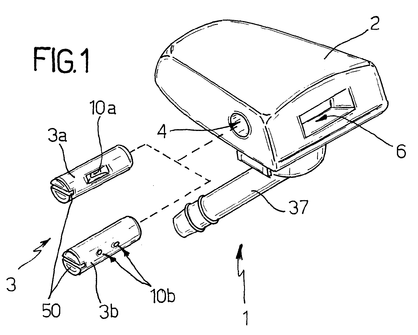
- A window-washer sprayer, in particular for vehicles, designed to generate at least one orientable jet of a detergent fluid towards a window to be cleaned, of the type comprising a sprayer body designed to be installed in a fixed position with respect to the window to be cleaned, and a cylindrical nipple installed laterally, idle and fluid-tight, within a transverse seat defined by said sprayer body; the latter moreover defining an internal duct, for the passage of said detergent fluid, and a side window made in a position corresponding to said seat and partially occupied in use by said cylindrical nipple; said window-washer sprayer being characterized in that said internal duct, said seat and said nipple have a geometry such that, when a flow of said detergent fluid is fed into said internal duct it splits, by fluid-dynamic effect, into a plurality of separate flows, which simultaneously reach said seat and are expelled through at least one through radial opening made through said cylindrical nipple in a position corresponding to said side window of the sprayer body.
- The window-washer sprayer according to Claim 1, characterized in that said seat of said sprayer body is designed to receive selectively a said cylindrical nipple of a first pre-set type, in which said at least one through radial opening is constituted by a single slit made longitudinally in the nipple, and a said cylindrical nipple of a second pre-set type, provided with a plurality of through radial holes arranged longitudinally in series parallel to a generatrix of said nipple; in such a way that one and the same sprayer body, when it is provided with a nipple of the first pre-set type, defines an orientable fluid-dynamic sprayer and, when it is provided with a nipple of the second pre-set type, defines an orientable filiform sprayer.
- The window-washer sprayer according to Claim 1 or Claim 2, characterized in that said sprayer body and said nipple are each constituted by a single moulded piece made of a synthetic plastic resin and may be coupled together, the latter in the former, via snap-action means.
- The window-washer sprayer according to Claim 3, characterized in that said sprayer body is provided with means for coupling to a support in a fixed position with respect to said window to be cleaned.
- The window-washer sprayer according to Claim 4, characterized in that it comprises, underneath, a collar provided internally with an axial seat designed to receive by snap action, in an idle and fluid-tight way, a hydraulic connector for a tube for delivery of a detergent fluid; said seat being set substantially coaxial with said internal duct.
- The window-washer sprayer according to Claim 5, characterized in that said internal duct is rectilinear and comprises a blind terminal portion delimited by a cylindrical side wall and by a plane bottom end wall, where said blind terminal portion has a rectilinear axis coaxial with that of said internal duct and substantially the same internal diameter; said transverse seat for the nipple and said side window of the sprayer body being made in a position such that an end facing the inside of the sprayer body of said through radial opening of the nipple is in use always positioned at a pre-set and relatively small distance from said plane bottom end wall of said blind terminal portion of said internal duct.
- The window-washer sprayer according to Claim 6, characterized in that said pre-set and relatively small distance present in use between said end facing the inside of the sprayer body of said through radial opening of the nipple and said plane bottom end wall of said blind terminal portion of said internal duct is of dimensions comparable with those of the width of the section of passage of said through radial opening of the nipple measured in the direction of the axis of symmetry of said internal duct.
- The window-washer sprayer according to either Claim 6 or Claim 7, characterized in that said hydraulic connector for a tube for delivery of a detergent fluid has an internal diameter substantially identical to that of said internal duct, in such a way that, in use, said cylindrical side wall of said blind terminal portion of the internal duct will be set substantially flush with an internal outlet edge of said connector.
Applications Claiming Priority (2)
| Application Number | Priority Date | Filing Date | Title |
|---|---|---|---|
| ITTO20040091 | 2004-02-17 | ||
| IT000091A ITTO20040091A1 (en) | 2004-02-17 | 2004-02-17 | MULTIFUNCTIONAL WASHER SPRAYER WITH ADJUSTABLE JET, IN PARTICULAR FOR VEHICLES |
Publications (3)
| Publication Number | Publication Date |
|---|---|
| EP1564095A2 true EP1564095A2 (en) | 2005-08-17 |
| EP1564095A3 EP1564095A3 (en) | 2005-12-28 |
| EP1564095B1 EP1564095B1 (en) | 2011-05-18 |
Family
ID=34685657
Family Applications (1)
| Application Number | Title | Priority Date | Filing Date |
|---|---|---|---|
| EP05101142A Expired - Fee Related EP1564095B1 (en) | 2004-02-17 | 2005-02-16 | A multi-purpose window-washer sprayer with orientable jet, in particular for vehicles |
Country Status (4)
| Country | Link |
|---|---|
| US (1) | US7204432B2 (en) |
| EP (1) | EP1564095B1 (en) |
| BR (1) | BRPI0500419A (en) |
| IT (1) | ITTO20040091A1 (en) |
Cited By (4)
| Publication number | Priority date | Publication date | Assignee | Title |
|---|---|---|---|---|
| WO2007019919A1 (en) * | 2005-08-18 | 2007-02-22 | A. Raymond Et Cie | Device for subjecting an object to the action of a liquid |
| WO2011033223A1 (en) | 2009-09-17 | 2011-03-24 | Mgi Coutier | Cylinder nozzle for a windscreen-washer system |
| EP3309019A1 (en) | 2016-10-13 | 2018-04-18 | Fico Transpar, S.A. | Washing system |
| EP3318452A1 (en) | 2016-11-07 | 2018-05-09 | Fico Transpar, S.A. | Fluid-ejection device |
Families Citing this family (5)
| Publication number | Priority date | Publication date | Assignee | Title |
|---|---|---|---|---|
| JP4668330B2 (en) * | 2009-04-16 | 2011-04-13 | シーケーディ株式会社 | Liquid ejection device |
| US10532368B2 (en) * | 2016-07-22 | 2020-01-14 | Fico Transpar, S.A. | Fluid ejection device |
| EP3501920B1 (en) * | 2016-07-22 | 2021-09-08 | Fico Transpar, S.A. | Fluid-ejection device |
| CN109276179A (en) * | 2018-11-16 | 2019-01-29 | 安吉罗氏铝合金箱包厂 | It is a kind of for cleaning the cleaning device of aluminum window frame |
| US20220009453A1 (en) * | 2020-07-09 | 2022-01-13 | A. Raymond Et Cie | Bracket and modular assembly for fluid spray system |
Citations (1)
| Publication number | Priority date | Publication date | Assignee | Title |
|---|---|---|---|---|
| WO2002060589A1 (en) | 2001-02-02 | 2002-08-08 | Fico Transpar, S.A. | Cleaning liquid spraying device for automobile windshield washer jets |
Family Cites Families (12)
| Publication number | Priority date | Publication date | Assignee | Title |
|---|---|---|---|---|
| US2898036A (en) | 1957-11-20 | 1959-08-04 | Gen Motors Corp | Windshield washer nozzle assembly |
| ES338399A1 (en) | 1966-03-28 | 1968-04-01 | Lavacristalli Foredit S P A | Improvements in liquid sprinklers for a vehicle windshield cleaner. (Machine-translation by Google Translate, not legally binding) |
| GB2250218A (en) | 1990-11-29 | 1992-06-03 | Engineering Research & Applic | Nozzle assembly |
| JP2600970Y2 (en) | 1993-07-23 | 1999-11-02 | 株式会社小糸製作所 | Headlamp cleaner |
| DE19742471C2 (en) | 1997-09-26 | 2002-03-14 | Mannesmann Vdo Ag | Windshield washing system |
| JP3492556B2 (en) * | 1999-06-25 | 2004-02-03 | アスモ株式会社 | Washer nozzle device for vehicles |
| DE19958196A1 (en) * | 1999-12-02 | 2001-06-07 | Mannesmann Vdo Ag | Window cleaning device |
| FR2803542B1 (en) | 2000-01-07 | 2002-03-22 | Renault | JET FOR WINDOW SURFACE WASHING LIQUID, ESPECIALLY A MOTOR VEHICLE |
| IT1319731B1 (en) * | 2000-12-22 | 2003-11-03 | Itw Automotive Italia S R L | SPRAYER OF A WASHING LIQUID FOR A VEHICLE |
| DE10115542A1 (en) * | 2001-03-28 | 2002-10-24 | Siemens Ag | Nozzle for a windscreen washer system for a motor vehicle |
| JP3768116B2 (en) * | 2001-05-11 | 2006-04-19 | アスモ株式会社 | Window washer nozzle and nozzle molding tool |
| DE10339505A1 (en) | 2003-08-27 | 2005-03-24 | Siemens Ag | For mounting in a motor vehicle provided device for cleaning a disc or a lens |
-
2004
- 2004-02-17 IT IT000091A patent/ITTO20040091A1/en unknown
-
2005
- 2005-02-15 US US11/057,230 patent/US7204432B2/en active Active
- 2005-02-16 BR BR0500419-5A patent/BRPI0500419A/en not_active IP Right Cessation
- 2005-02-16 EP EP05101142A patent/EP1564095B1/en not_active Expired - Fee Related
Patent Citations (1)
| Publication number | Priority date | Publication date | Assignee | Title |
|---|---|---|---|---|
| WO2002060589A1 (en) | 2001-02-02 | 2002-08-08 | Fico Transpar, S.A. | Cleaning liquid spraying device for automobile windshield washer jets |
Cited By (4)
| Publication number | Priority date | Publication date | Assignee | Title |
|---|---|---|---|---|
| WO2007019919A1 (en) * | 2005-08-18 | 2007-02-22 | A. Raymond Et Cie | Device for subjecting an object to the action of a liquid |
| WO2011033223A1 (en) | 2009-09-17 | 2011-03-24 | Mgi Coutier | Cylinder nozzle for a windscreen-washer system |
| EP3309019A1 (en) | 2016-10-13 | 2018-04-18 | Fico Transpar, S.A. | Washing system |
| EP3318452A1 (en) | 2016-11-07 | 2018-05-09 | Fico Transpar, S.A. | Fluid-ejection device |
Also Published As
| Publication number | Publication date |
|---|---|
| BRPI0500419A (en) | 2005-10-04 |
| EP1564095A3 (en) | 2005-12-28 |
| US7204432B2 (en) | 2007-04-17 |
| ITTO20040091A1 (en) | 2004-05-17 |
| EP1564095B1 (en) | 2011-05-18 |
| US20050178852A1 (en) | 2005-08-18 |
Similar Documents
| Publication | Publication Date | Title |
|---|---|---|
| EP1564095B1 (en) | A multi-purpose window-washer sprayer with orientable jet, in particular for vehicles | |
| US7111793B2 (en) | Washer nozzle and washer apparatus | |
| US20180029566A1 (en) | Compact Split-Lip Shear Washer Nozzle | |
| US6074078A (en) | Lamp assembly with fluid dispensing nozzle | |
| US20030192964A1 (en) | Adjustable hose end sprayer nozzle | |
| US6354515B1 (en) | Washer nozzle device for vehicles | |
| US11465595B2 (en) | Automotive image sensor surface washing and drying system and method | |
| EP1673260A2 (en) | Cleaning device | |
| SE469787B (en) | Spray nozzle assembly for a spotlight cleaner | |
| CN108602073B (en) | Micro-scale structure and construction method for fluid oscillator cleaning nozzle | |
| US20050121539A1 (en) | Vehicle lamp washing device | |
| US20070018012A1 (en) | Nozzle and method of making the same | |
| US20060243823A1 (en) | Device which is provided for fixing in a motor vehicle and is intended for cleaning a window or a headlamp lens | |
| CN115803235A (en) | Nozzle, nozzle assembly and cleaner device | |
| EP1504973A2 (en) | Vehicular washer nozzle and vehicular washer device having diffusion regulating structure | |
| JP2007320498A (en) | Washer nozzle incorporating-type high mounted stop lamp | |
| US5480289A (en) | Connector and mounting arrangement for a windshield washer pump | |
| CN214962162U (en) | Nozzle, injection device and operation equipment | |
| EP2148015B1 (en) | Sanitary fitting with light conducting discharge tube | |
| US11091127B1 (en) | Windshield wiper with jet ejectors for use in vehicles | |
| GB2362812A (en) | Windsreen wiper harness with water supply passing through central pivot sleeve | |
| BRPI0500419B1 (en) | MULTIPURPOSE SPRAYER FOR WINDOW CLEANER WITH ORIENTABLE JET SPECIFICALLY FOR VEHICLES | |
| CN113799739A (en) | Wiper and vehicle | |
| WO2022186031A1 (en) | Spray nozzle | |
| EP1216903B1 (en) | Automotive cleaning fluid sprayer |
Legal Events
| Date | Code | Title | Description |
|---|---|---|---|
| PUAI | Public reference made under article 153(3) epc to a published international application that has entered the european phase |
Free format text: ORIGINAL CODE: 0009012 |
|
| AK | Designated contracting states |
Kind code of ref document: A2 Designated state(s): AT BE BG CH CY CZ DE DK EE ES FI FR GB GR HU IE IS IT LI LT LU MC NL PL PT RO SE SI SK TR |
|
| AX | Request for extension of the european patent |
Extension state: AL BA HR LV MK YU |
|
| PUAL | Search report despatched |
Free format text: ORIGINAL CODE: 0009013 |
|
| AK | Designated contracting states |
Kind code of ref document: A3 Designated state(s): AT BE BG CH CY CZ DE DK EE ES FI FR GB GR HU IE IS IT LI LT LU MC NL PL PT RO SE SI SK TR |
|
| AX | Request for extension of the european patent |
Extension state: AL BA HR LV MK YU |
|
| 17P | Request for examination filed |
Effective date: 20060628 |
|
| AKX | Designation fees paid |
Designated state(s): DE ES FR GB IT SE |
|
| 17Q | First examination report despatched |
Effective date: 20060811 |
|
| GRAP | Despatch of communication of intention to grant a patent |
Free format text: ORIGINAL CODE: EPIDOSNIGR1 |
|
| GRAS | Grant fee paid |
Free format text: ORIGINAL CODE: EPIDOSNIGR3 |
|
| GRAA | (expected) grant |
Free format text: ORIGINAL CODE: 0009210 |
|
| AK | Designated contracting states |
Kind code of ref document: B1 Designated state(s): DE ES FR GB IT SE |
|
| REG | Reference to a national code |
Ref country code: GB Ref legal event code: FG4D |
|
| REG | Reference to a national code |
Ref country code: DE Ref legal event code: R096 Ref document number: 602005028056 Country of ref document: DE Effective date: 20110630 |
|
| PG25 | Lapsed in a contracting state [announced via postgrant information from national office to epo] |
Ref country code: SE Free format text: LAPSE BECAUSE OF FAILURE TO SUBMIT A TRANSLATION OF THE DESCRIPTION OR TO PAY THE FEE WITHIN THE PRESCRIBED TIME-LIMIT Effective date: 20110518 |
|
| PG25 | Lapsed in a contracting state [announced via postgrant information from national office to epo] |
Ref country code: ES Free format text: LAPSE BECAUSE OF FAILURE TO SUBMIT A TRANSLATION OF THE DESCRIPTION OR TO PAY THE FEE WITHIN THE PRESCRIBED TIME-LIMIT Effective date: 20110829 |
|
| PLBE | No opposition filed within time limit |
Free format text: ORIGINAL CODE: 0009261 |
|
| STAA | Information on the status of an ep patent application or granted ep patent |
Free format text: STATUS: NO OPPOSITION FILED WITHIN TIME LIMIT |
|
| 26N | No opposition filed |
Effective date: 20120221 |
|
| REG | Reference to a national code |
Ref country code: DE Ref legal event code: R097 Ref document number: 602005028056 Country of ref document: DE Effective date: 20120221 |
|
| GBPC | Gb: european patent ceased through non-payment of renewal fee |
Effective date: 20120216 |
|
| REG | Reference to a national code |
Ref country code: FR Ref legal event code: ST Effective date: 20121031 |
|
| PG25 | Lapsed in a contracting state [announced via postgrant information from national office to epo] |
Ref country code: GB Free format text: LAPSE BECAUSE OF NON-PAYMENT OF DUE FEES Effective date: 20120216 Ref country code: FR Free format text: LAPSE BECAUSE OF NON-PAYMENT OF DUE FEES Effective date: 20120229 |
|
| PGFP | Annual fee paid to national office [announced via postgrant information from national office to epo] |
Ref country code: DE Payment date: 20140227 Year of fee payment: 10 |
|
| REG | Reference to a national code |
Ref country code: DE Ref legal event code: R119 Ref document number: 602005028056 Country of ref document: DE |
|
| PG25 | Lapsed in a contracting state [announced via postgrant information from national office to epo] |
Ref country code: DE Free format text: LAPSE BECAUSE OF NON-PAYMENT OF DUE FEES Effective date: 20150901 |
|
| PGFP | Annual fee paid to national office [announced via postgrant information from national office to epo] |
Ref country code: IT Payment date: 20180222 Year of fee payment: 14 |
|
| PG25 | Lapsed in a contracting state [announced via postgrant information from national office to epo] |
Ref country code: IT Free format text: LAPSE BECAUSE OF NON-PAYMENT OF DUE FEES Effective date: 20190216 |