EP1566873A2 - Protection circuit group with ring structure for power electronics control devices - Google Patents
Protection circuit group with ring structure for power electronics control devices Download PDFInfo
- Publication number
- EP1566873A2 EP1566873A2 EP05101273A EP05101273A EP1566873A2 EP 1566873 A2 EP1566873 A2 EP 1566873A2 EP 05101273 A EP05101273 A EP 05101273A EP 05101273 A EP05101273 A EP 05101273A EP 1566873 A2 EP1566873 A2 EP 1566873A2
- Authority
- EP
- European Patent Office
- Prior art keywords
- signal
- safety
- output
- input
- ring
- Prior art date
- Legal status (The legal status is an assumption and is not a legal conclusion. Google has not performed a legal analysis and makes no representation as to the accuracy of the status listed.)
- Granted
Links
Images
Classifications
-
- G—PHYSICS
- G05—CONTROLLING; REGULATING
- G05B—CONTROL OR REGULATING SYSTEMS IN GENERAL; FUNCTIONAL ELEMENTS OF SUCH SYSTEMS; MONITORING OR TESTING ARRANGEMENTS FOR SUCH SYSTEMS OR ELEMENTS
- G05B9/00—Safety arrangements
- G05B9/02—Safety arrangements electric
- G05B9/03—Safety arrangements electric with multiple-channel loop, i.e. redundant control systems
-
- G—PHYSICS
- G05—CONTROLLING; REGULATING
- G05B—CONTROL OR REGULATING SYSTEMS IN GENERAL; FUNCTIONAL ELEMENTS OF SUCH SYSTEMS; MONITORING OR TESTING ARRANGEMENTS FOR SUCH SYSTEMS OR ELEMENTS
- G05B9/00—Safety arrangements
- G05B9/02—Safety arrangements electric
Definitions
- the invention deals with safety aspects of power electronics devices, which are often in use as "control units of power electronics", so For example, as a frequency converter or inverter or other inverter, the are provided for operating an electric motor drive.
- Applicable is the Invention also in the environment of hydraulics or pneumatics, provided for the control, or wherever multiple devices are to be security-monitored together.
- electrical, hydraulic or pneumatic controls and drives are not only independently operated, but also mechanically coupled.
- the mechanical Coupling for example as a transmission, or another composite in the sense of a electric wave, it requires that all independently controlled and operated Driven to have an overarching security concept that theirs controls, initiates and monitors virtually the same safety reaction. It must be there be avoided that the safety shutdowns of such drives different work, even if each drive disconnected independently and independently but there is a mechanical coupling between the drives which themselves are not is capable of safety shutdown from one drive to the other Drive to transfer.
- the invention has therefore made the problem, a Safety shutdown in such a way that it works more reliably and thereby nevertheless able to address faster.
- Opposite a star concept central Evaluation of feedback of many devices or drives
- Programming costs are reduced, special circuits largely avoided and reliability, as well as flexibility, by admitting any Number of security levels to be increased.
- the invention solves this extensive task by the realization of a Ring concept or a ring structure, in which individual safety circuits as Security levels are turned on. These "stages” are not hierarchical Stages, but treat all cascaded participants in the security ring the same.
- a safety circuit for switching into such a ring, with a multi-channel input and a multi-channel output allows the ring from at least two security levels build (claim 1).
- a built-up of several (at least two) security levels ring as a safety circuit group ensures a reliable shutdown at different (not same) logic levels or combinations of logic levels on a multi-channel Output (claim 20).
- the Has subscribers who are connected in the ring network using at least two-channel signal routing in the ring are already assumed by a composite, the Has subscribers who are connected in the ring network using at least two-channel signal routing in the ring.
- a safe shutdown method uses several of the Safety circuits (claim 1), but is in its operation by specifying the Signal effects characterized as a method (claim 15).
- the passing on (passing through) of a shutdown signal is done quickly, by "Propagation" in the ring composite, starting from a trigger, as the triggering Participant couples the shutdown signal in the ring network.
- the described control units of the power electronics are independently regulated, but influenced by a higher-level control or regulation.
- Each of these Devices has its own security components, security identifiers and also peripheral security areas, which deliver security-relevant signals.
- one respective such power electronics circuit for controlling electrical Drives is assigned a safety circuit, which in turn is in the ring compound is switched.
- these signals are from the Ring decoupled and detected in a safety area of a respective drive, or if a security case is detected (hardware error or function of a Safety sensor) in the control area of the drive in the ring Logic circuits coupled.
- the ring structure is a direct passing of an input signal, only via logic gate to an output signal of a safety circuit (assigned a control unit of the power electronics), without affecting the transmission of the signal in the ring the control unit must functionally influence to the passing of the signal to reach (claim 10).
- the logical ring is independent of the real response of security functions or the recognition of a AbschaltShes from the signal levels of the ring, as in a Security area of each control device is detected (claim 8, Claim 12).
- Safety signals are used in each control unit based on an observation of the signals the ring recognized, on the other hand also coupled into the ring, if a Security situation is detected by the controller. There is even the passing on and coupling of a detected at the input of a safety circuit AbschaltMap to its output possible to occur errors within a Logic structure in the ring to bridge and the error signal of the input to the Once again connect the output of a respective safety circuit independently can (claim 12).
- the term "also pre-coupled” means that the direct Coupling via the logic gates (claim 3, claim 5, claim 14a, claim 14b) in any case (or: permanently) is given, if no line or malfunction the gates are present and only in addition, a parallel pass by or Hubüberkoppeleln an error signal from the input to the output via the safety area (Claim 12) is possible.
- the security area uses the same ways as he is one in his field and for his power electronics or his drive or the associated environment recognized fault condition as a multi-channel shutdown signal in would couple the output of the associated safety circuit (claim 11).
- test signals This allows short, pulse-like test signals to a respective output be switched (claim 7), which is an asymmetry of the levels for the duration of Impulses, so in the multi-channel output signal, without immediately the following safety area detects a shutdown.
- the impulses have a short one Duration of less than 1 msec and occur relatively rarely, for example, in one time interval from 10 times to 100 times greater than the pulse width of the Test impulse to determine long-term, whether malfunction or error exist on the lines, such as mechanical defects, such as Cross-couplings, duration zero or duration one or interruptions.
- the test signals are evaluated in terms of their effect on the potential of the line, which circuit arrangements are known as such but so they are not here be further explained, for example, an XOR element.
- test signals are treated in the ring but that they only ever one Section far influence, so from the output circuit of a first Security level to the entrance of a second security level, or only in one Input gate in which suppresses or hides these test pulses, so that Do not touch the output stage of the next safety circuit in the ring be passed on. Rather, this output stage receives test signals on its own coupled, which in turn only to the entrance of the next Enter safety circuit and hidden or suppressed here.
- the Function of the ring can be maintained so without a test signal through propagated the entire ring and runtimes accumulate in such a way that unwanted operating conditions arise, just from the test signals should be avoided.
- test signals have in the ring so only a limited duration or effect distance, be from any safety circuitry for their output until the next input but independently specified.
- the concept of ring switching works at different times or Time periods, the described shutdown delay of the safety area, the short pulse times of the test signals, the very short running time of the logic gates in one respective safety circuit, which logic gates are inventory of the logical ring, and a turn-on time to be explained later which fades out the Input signal by controlled influence serves and thus the reactivation of the Rings made possible from an addressed off state.
- the ring has a (meta) stable queuing, mostly with parallel high logic levels is defined on all multi-channel lines. Disturbing this situation may be the described test pulses, each acting a limited distance, but are kept so short that they delay the response of the Safety areas do not overcome and even in the ring only a limited Have effect, so not on the next stage (the next Safety circuit) addition effect.
- the logic zero level propagates directly through the entire ring, only delayed by the propagation delays of the logic gates in the ring, which in the Nanosecond range.
- the entire ring is then at logical zero placed (response or safety position). It then takes the response times of individual security areas until all have addressed and the associated Drives assume appropriate safety conditions.
- the safety conditions should only be indicated here.
- categories of shutdown the direct shutdown of category zero (torqueless switch), the controlled shutdown in the sense of a quick stop, as category 1 (the Zero speed value is controlled), and there is the category 2, which with Moment the speed gets zero controlled.
- category 1 the Zero speed value is controlled
- category 2 the Zero speed value is controlled
- the control is through Torque to zero speed, with errors in the basic unit, this control but not done so that a momentless switching is specified.
- the described shutdowns have mainly this goal, after a high Need to meet security requirement, work fast, synchronously all Disconnect drives and even error-free for all practically conceivable defects have to react.
- the ring can only be activated altogether, become intermediate sections of the ring, between, for example, an output and an input of the next stage not together with respect to the at least two channels in the same way with a logic zero is activated, there is a circuit fault or one of the described mechanical defects in the functional ring. To avoid these mistakes serve the test signals, which should detect such errors early and equal to one Shutdown to maintain the permanent function of the ring concept.
- the ring design works with any number of participants and can be arbitrary be cascaded. Despite the arbitrarily high number of participants is none Separate extension of input signals needed, rather speaks a safety circuit only the sequential circuit, to pass on any necessary Shutdown signal, and receives from the upstream safety circuit a possibly to be executed shutdown signal. Both signals are multi-channel, in the sense of at least two channels.
- the resulting electrical network in which the safety circuits provided be (electrically connected) is independently capable of acting, responsive and in the propagation of a shutdown signal is extremely fast, for example at three ring participants each with two logic gate run times per safety circuit in the range of a few 10 nsec. Greater than these transit times are the pulse durations the test pulses, again larger than these pulse durations are the Response delays of the safety areas of each of the control units, in turn greater than this is the mean time between the return of the test pulses and again greater than this one is the input stage of a respective safety circuit overriding or disabling start pulse.
- So-called safety times are even safer than this time Stopping a control unit (inverter enable, WR_EN).
- the safety time until the shutdown of an example inverter is application specific and depends on the drive. It can be between 100 ms to 30 seconds.
- the Shutdown of the inverter does not take place immediately then when the The safety area of this ECU is detected by the logic states of the ring has an error case and after expiration of the minimum time interval also has initiated a shutdown, but possibly much later. Induced is the Shutdown state, however, the execution is only application-specific in its real time vary.
- the tapping ("listening" or watching) of a shutdown signal from the logical Ring structure can be variably changed via a circuit arrangement, depending from the system and security state of a respective control device or a respective drive.
- a default can take place, between the categories 0, 1 or 2.
- the function and integrity of the logical ring structure does not become that touched. It remains with a direct passing in each safety circuit.
- test pulses which are time-delayed in the ring structure a respective output of a circuit arrangement (claim 1) coupled (claim 25, feature (c)).
- the injected test pulses are delayed, So do not occur in parallel or overlapping on the multiple channels, in particular not on both channels simultaneously. They monitor the output line up to next input and will be from one input circuit in the next Security circuit held at their further spread.
- the reduction of the number of channels ie the reduction of, for example, two channels between output of the pre-stage and input of the following stage is in the ring network expanded by the output circuit back to the original channel number, ie veriolofacht.
- a new test signal be coupled to the next section of the ring circuit in Check the distance of the pulses.
- the corresponding voltage measurements, as Sequence of impulses are triggers of the detection of mechanical defects in the Ring structure.
- Detected is a single-channel error signal, due to the presence of at least two channels, a multi-channel error signal is passed on, coupled into the ring structure.
- the condition of the ring tilts within less 10 nanoseconds, with the consequence of detecting a desired shutdown, too through the other security areas of the other controllers, in the above described sense.
- a single-channel detected error can also be multichannel detected error to be passed, this error detection the is more likely, as it is the rule (claim 20, second alternative). Both error detections can be easily combined and can alternatively accommodate to grab.
- Output stage and input stage of a respective safety circuit so have independent tasks, are functionally separated and are considered by a single-channel signal connected together (claim 5, claim 25). Together Form a section of the ring structure that corresponds to a particular safety circuit assigned. Between these sections are pipe sections leading to the each next section of the safety circuit, again consisting of the Input circuit and the output circuit, lead. So has considered a respective Safety circuit an input circuit and output circuit, which one channel is connected. Functionally, however, an output circuit always works a safety circuit with an input circuit of the next Safety circuit together, which is assigned to different drives and in the connected with lines form is not delivered, but logically in this Form must be declared coherently.
- an override of the input stage (input circuit) of a respective one helps Security circuit, for example, by supplementing another input of the Or function on which input a one-signal is turned on, if all other safety conditions for the reconnection of the coupled drives are fulfilled.
- This signal is for a short time, for example between 20 msec and 100 msec active, overrides the logical zero to be passed from the switch-off position at the input, in favor of a momentarily forced one-state (high level) on the single-channel intermediate signal between the input circuit and the Output circuit of the safety circuit to allow it at the output, there also by pre-controlling one-signals on both channels a multi-channel To give one information as the output signal to the next input signal.
- the override or blanking signal can be activated said signal on all input circuits are switched off.
- the ring stays in its (metastable) waiting state.
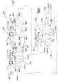
- Figure 1 illustrates a ring structure of three circuit arrangements and three Drives with assigned inverter (frequency converter).
- the frequency converter as Representatives of a circuit of the power electronics are not shown separately, they are well known.
- the drive C abbreviated AC has a Security area C33 from at least two microcontrollers ⁇ C1, ⁇ C2 on which the Input signals c10b (t) and c10a (t) detected, derived therefrom an error condition and according to preset switching mechanisms and control specifications a stop such as category zero, category one or category two. This can be additionally adjustable and selected.
- a periphery for safety sensors represented by the other two Drives AA, AB and the associated sensor range A50 and B50 are additional Signals for evaluation to the respective safety circuit A33 or B33, too Security area of the respective drive or the inverter called.
- the drive C has no such separate peripheral safety sensor, but only one Intrinsic safety represented by C33.
- Each area of a drive AA, AB and AC with associated inverter has one Logic section, which is enlarged here and shows the distribution of the Assigned safety signals of a respective drive. The over the Logic area beyond control elements of the inverter are not shown.
- the three predetermined drive ranges AA, AB and AC with their respective logic range A, B and C are comparable from the internal structure, In particular, the logic area A, B and C are the same. The description is done therefore significantly in the area A of the drive AA, can with regard to the components and functions directly on the logic areas B of the drive AB and C of the Drive AC are transmitted.
- the reference numerals are the same, only with the labeled letters.
- the entrance A10 corresponds to the Drive range AA the input C10 of the drive range AC and this again the entrance area B10 of the drive area AB.
- the Outputs A20, C20 or B20 are comparable from the internal structure, In particular, the logic area A, B and C are the same. The description is done therefore significantly in the area A of the drive AA, can with regard to the components and functions directly on the logic areas B of the drive AB and C of the Drive AC are transmitted.
- the reference numerals are the same, only with the labeled letters.
- the entrance A10 corresponds
- the signals are labeled with lowercase letters and in the apparent multi-channel design, shown here two-channel, are each two Input signals independently but parallel and two output signals independently and parallel.
- a respective output of a safety circuit is over the mentioned two channels on the entrance of the next (following) Safety circuit switched. Their output will turn to the next but one Input and its output to the first input of the output circuit fed back. This creates a ring structure, which in the three shown Safety circuits is made in the manner described.
- the said ring structure consists of several sections.
- a respective one Logic section is assigned to a safety circuit and consists of a Input circuit A30 and a subsequent output circuit A40, respectively also the input circuit C30 and the output circuit C40 of Safety circuit C on the drive CC.
- the outside of the logic sections lying Ring sections are cable guides, in the described, at least two channels trained structure of independent signals that are in regular operation, ie without mechanical or electrical defects have the same logical level, anyway considered stationary.
- a normal logic switch-on level, no switch-off and no error symbolizes, is a logical one (high level) on all line sections. That is true then also for the exemplified signals a10a and a10b. They come from from the output C20 of the safety circuit C, coupled to Safety circuit A. There are the signals c20a (t) and c20b (t).
- the redundant can consist of several, here two microcontrollers ⁇ C1, ⁇ C2, which are the logical Take over safety shutdown and work with a switching delay.
- These Switching delay T1 entails that a change of the two channels on the Low state (logical zero) a shutdown of the safety area and a Detection of the error case only after this response delay causes.
- T1 is located in the range of preferably above 1 msec, but can also be chosen lower, above 500 nsec.
- Safe shutdown of a drive is achieved either by activating one of the Sensors in the periphery (as active or passive sensor) designed.
- a Sensor can, for example, a light grid, a safety mat or a Be photocell. Your signals are sent to the security area, for example C33 with drive C or A33 with drive A.
- the shutdown information of A50 thus obtained initially concerns the range of Propulsion A. To further-mediate it is duty of the ring that out Logic components a very low duration T0 in the sense of propagating a Off signal has.
- the security area A33 feeds a multi-channel Off signal via the signal outputs O1 and O2 to two AND gates A40b and A40A. If the signals O1 and O2 go to zero, the output signal becomes zero, too at the output A20 as two independent signals, but parallel and essentially simultaneously switch to logical zero, appears. About the intermediate section of the Cable routing, this shutdown signal to the input B10 of the next Security level B forwarded.
- safety circuit A passes in a similar manner, the output signal the output C20 of the safety circuit C, via the two signals c20a (t) and c20b (t) to input A10. Again, there are independent signals, but parallel switch to zero when the low signal of input B10 through the logic gates of the Security level B and the input circuit C30 of security level C is propagated to appear at output C20.
- the logic signals a10a (t) and a10b (t) arrive at substantially the same time OR gate C30, which is the input circuit of the ring structure in the Safety circuit A represents.
- the input circuit A30 takes the multi-channel Signal of the input A10, is designed as a functional element, from this multichannel input signal an intermediate signal a30 (t) reduced in the number of channels with zero input to zero switches to the AND gates of the output circuit A40 again with multiple channels to supply a zero signal, but has no further effects after these gate circuits trigger and the einkoppelnde element of the shutdown signal were in the ring.
- the entire ring is now at a low potential, which is all Routing between the ring sections within the safety circuits concerns, and in addition also the entire signal lines of the logic modules of Safety circuits themselves concerned.
- the safety signal here the change from the waiting stable, actually metastable one state to the stable zero state, which is an error case and a shutdown symbolizes, is achieved reliably and quickly.
- All Safety areas A33, C33 and correspondingly also the switch-off area B33 can now due to given own logic the pre-marked shutdown carry out. None of these security areas was involved in the forwarding of the Ring propagating shutdown signal involved, but the ring is independent on Zero tipped, very fast and only delayed by the sum T0 of the maturities of the Ring involved logic gates.
- Each on the input side and output side interconnected safety circuit is therefore in the ring composite (the ring structure) for monitoring all of the ring structure Participants involved and their drives and control units.
- the regular operating case was described as here all circuits are working properly work and the lines no faults or mechanical defects, such as Cross-couplings, fixed zero signal or fixed one-signal or an interruption exhibit.
- the security case here is assumed the situation where all signals tilt to logical zero. It can also be realized the reverse logic, but preferably the switch-off at the logic signal level is zero. This represents the Security case and the secure position of the ring.
- a multi-channel input circuit and a multi-channel output circuit the same safety circuit are in the manner described by the Signal a30 (t), correspondingly also the signal c30 (t), coupled, which output signal the input circuit A30 and C30 is.
- An OR function may include test pulses 100 that are not simultaneous at all, here the two channels appear to be hidden.
- These controlled test signals a pulse circuit C35 of the safety circuit C, coupled here via the Output circuit C40, the output C20, on to the input A10 and the Input circuit A30 does not extend in its effect, as to this Input circuit.
- pulse circuits A35, B35 are also any others Safety circuit assigned, which also has only a limited section of the Rings check, starting from the output of, for example, A20 to next input circuit B30. The test pulses are in the respective, the Input circuit forming function member locked and it can not happen.
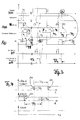
- test pulses which in FIG. 4 have a small pulse width T2a, T2b are shown are coupled as pulses 100 to the signals in their pulse width but narrower than the response delay T1 of each of the involved Security areas C33, A33 and B33. This is a prerequisite that none of Security areas responded by the test signals, but at the same time a independent verification of the functionality of the ring structure ensured can be.
- the security areas respond especially even if an imbalance the level at its input is present for a longer time than the Response delay T1. This is called a mechanical or electrical defect interpreted, which will lead to a safe shutdown.
- the minimum number of ring participants is two, if e.g. only the Safety circuit A and B are used, coupled to output A20 to Input C10.
- the pulses 100 are superimposed on the signal lines to to produce unbalanced logic levels, which are so short that the Safety areas C33 and A33 not yet responding.
- the logic levels will be therefore not simultaneously on all parallel channels in a respective section between the output and the input of two adjacent safety circuits created, but time-shifted and thus not overlapping.
- the temporal Spacing T4 or the repetition rate of the test pulses can be significantly longer as their pulse width, so between 10 times to over 100 times longer, which is due to the Time interval T4 is illustrated in Figure 4.
- the non-overlapping Test pulses 100 are shown on both signals c20b (t) and c20a (t). It turns out from this, the single-channel intermediate signal a30 (t), after the input circuit A30, the has hidden or does not pass these test pulses.
- a shutdown case that is not automatic and independent, regardless of the Addressing one of the safety circuits A33, C33 or B33 by the Logic circuits of the ring is propagated, the one by electrical or mechanical defect caused asymmetry of an input A10, or the here incoming input signals. These can be past the logic gates by the Safety area after the minimum interval T1 has elapsed (as a response delay) the input circuit A30 bypassed and coupled in the output A40 become. This is an additional way to get more or more security, but not required for the actual function of the ring. The function of the ring rather, it is ensured, regardless of a response or non-response one of the safety areas (as signal or safety shutdown C33, A33 and B33).
- Both the ring works independently and independently, as well as the shutdown of a independent drive takes place independently. They are coupled via listening to the Input (for the disconnector detection) and by coupling the switch-off signal on Output (for the transmission of the switch-off signal).
- the shutdown of a security area is also the same Security area undone.
- the shutdown triggering safety area A33 assuming response of the Sensors A50, a one-way signal on the third input of OR gate A30 - after Arrival of an acknowledgment pulse to NA-Q and elimination of the sensor response - placed.
- the release also acts on the shutdown signals O1, O2, so that the inner Section of the ring in the area of security level A by external influence on logically one is placed.
- the output A20 is thus forced multi-channel logic one.
- the cascading and the propagation override the null signal. Achieving this disempowerment Signal q (t) is only pulsed, so it falls after a short period T3, for example greater than 10 msec or greater than 20 msec away, at which time it no longer is needed to hold the ring in its one state.
- the pulse duration of this Signal should be greater than the response delay of the safety areas.
- the overdriving the input circuit for example, the input circuit C30 on the third input is from the security area concerned only if both participating microcontroller give the enable signal, in area C is the Security area C33, the AND gate C31 and the control of this AND gate of both microcontrollers involved in security area C33.
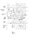
- the operation when triggering the response of the sensor A in Security range of the drive AA is schematically illustrated in Figure 2, with Timing diagrams and logic levels.
- the triggering takes place a shutdown information and the forwarding of this information starting with the Addressing, for example, the sensor A50, digit (1) (circled numerals in Figure 2).
- the predetermined edge is virtually instantaneous over the entire Ring structure A20, B10, B20, C10, C20, A10 further coupled after entering the Output signal A20 was coupled via the output stage A40.
- the sensor B50 does not remain activated, ie trouble-free.
- Each inverter has an S time T5 for safe shutdown. This time is (clearly) greater than the turn-off delay T1.
- the falling edge of the associated signal "Safe shutdown” represents the end of the shutdown sequence.
- the drives are located yourself in a stop category.
- a manual acknowledgment will be made parallel to acknowledgment inputs NA-Q-In of all drive ranges.
- the signal is q (t). After being taken over by a falling flank, only the local Sensor inputs evaluated in each safety module. This local Sensor inputs affect the range of the inverter, no sensor inputs from Shutdown sensors or monitoring sensors of other drives and none Ring information.
- the input of the safety circuit A is at (1 c) for a short time T3, for example, 20 msec hidden.
- Both microcontrollers of the Security area A33 set a logical one to the AND gate A31, whose Output e (t) is passed to the third input of the OR gate A30. This will be the Output circuit A40 from the two AND gates A40a, A40b unlocked.
- the internal signal O1 / O2 multi-channel will switch to the desired multi-channel logic one level switched and propagated to the next party. All parties Participants in the ring behave this way until at input A10 of safety circuit A a logical one signal is pending at (1e). This was possible because of the other drives AB and AC no sensor required a shutdown, so Enabled signals and q (t) was supplied synchronously to all subscribers.
- the release of the respective drive, or then all drives, takes place after expiry of the Delay time T5, here given, for example, 5 msec, following the falling edge of e (t), not before.
- the blanking time T3 is significantly greater than the running time, both one Participant from the ring, as well as all terms seen in total, so the Total running time in the ring.
- n symbolizes the number of connected in the ring Attendees.
- all ring participants behave in terms of their Contribution to the total duration equal. If one assumes a total running time T0 in the ring out, the running time T0 / n per ring taker is divided in the first place the total running time by the number of ring participants. It is also according to the switch-on according to the above diagram shows that the delay time T5 as a start delay of Drives is much larger than the running time in the ring, in terms of total running time T0.
- the numeral (2) shows the response of the security area A33, the passing and Coupling of this signal into the output A20, which propagates through the ring Signal to input A10 back (from the cascading), and the response time of the safe shutdown with the S-time T6. Shall be switched off again State are turned on again and it is assumed that in (2a) the Sensor A50 still requires a shutdown, this happens in the following Figure 2 Sketched with the already known signals.
- a contributing fact is the only local evaluation of the safety signal from the respective sensor.
- the evaluation concerns the input, not the output, with the sensor activated (blocking signal assumed) always remains deactivated when the associated sensor has responded and is still in this state.
- the evaluation in the entrance area and the passing on of the exit area becomes by the two security signals possible, of which the one signal e (t) the Override in the entrance area caused when you want to turn on, and the other safety signals are O1 and O2 which are supplied to the output area but continue to block and nothing from the overdrive signal passing the associated AND gates through, which is manually impressed Pre-control to induce is specified.
- every ring participant becomes independent in the same way Pre-controlled entrance area, considers only the local sensor information, which in the Output range either continues to be blocking or already releasing, and will do so each put in an intermediate state, which makes it possible to return the ring in the actively waiting wait state, if all sensors, in the example A50, B50 and that of the security area C33, no longer addressed. Then the intermediate state changes to the metastable waiting state to be reached Now and in a row, any future reported failure is fast, reliable and to convey this to all other ring participants with high precision.
- overdrive signal e (t) are two of the three safety circuits in the ring in their respective output, here B20 and C20, controlled at logical one, so that the Ring is supposedly functional, up to the input signal A10, only the Output signal A20 and the input B10 of the sequential circuit are influenced by the non-e (t) override output range A40 of the safety circuit A to zero.
- This logical zero can be detected by the inhibiting signal e (t) of the safety circuit B but not propagate through the ring and only then receives a propagation release, when the effect of signal e (t) disappears after the elapse of time T3.
- the safety circuit A was considered, the Response of the associated sensor A50 and the effects that the Response of the sensor after propagation of the safety signal over the others both participants B and C turn on the same triggering Safety circuit A generates (their input), so shall in another example be shown how the signals affect when the security area B responds, and what effect on the input signal A10 of the Safety circuit B upstream safety circuit results, ie the am farthest circuit in the ring.
- the same consideration can equally well Replacement of the associated reference numerals B and C for the safety circuit C done, with effect on input B10. She can do likewise for the Safety circuit A, with effect on the input C.
- the activation of the sensor B50 is illustrated, the according to the activation of the sensor A50, only for the drive range AB is working.
- the output B20 activating after coupling into the ring on the Gate circuit B40 multichannel signaled and propagated through the (entire) ring via the safety circuits C to the (farthest) input A10.
- This is at (1a) illustrates, by a multi-channel zero signal, the safe shutdown of the safety area A33 at (1c). The shutdown happens after expiration
- the time T6 named as S-time, depends heavily on the application, so in one wide field from faster applications at 100 msec to very slow responsive driving large machines up to 30 sec.
- a Response delay T1 which is above the duration of the test pulses, for example, above 1 msec for test pulses below this order of magnitude.
- Virtually coinciding with the falling edge of A10 is time delayed by one Fraction of the runtime this edge is also present at the output A20, which at (1b) in third diagram is shown from above. This "message" closes the circle, with the Fraction of the number of participants in the circle is determined, as indicated above.
- the sensor B50 After the manual intervention time T3, caused by the manual Acknowledgment q and the blanking time specified by the system in one Magnitude substantially above T0, for example in the range of 10 msec to 20 msec, the sensor B50 is no longer activated for the example according to FIG logic high level), so that the one-logic signal at 1 e in the third diagram of down to logical one, both at input A10, as shown, as also at exit A20. Starting from this signal position is after the end of Blanking time T3, after expiration of the delay time T1 and after expiration of the Blanking time T5 of drive A enabled.
- the times which are shown in an overview below, are based on a fast drive with triggering converter.
- Overview time type Magnitude of the time type annotation T0 (whole ring) ⁇ 60 nsec with three participants in the ring medium speed logic T1 (response) > 1 msec, is bigger T2a T2a (test peaks) between 500 ⁇ sec T2b and 1 msec T3 20 msec much bigger than T0 T4 > 10 msec, too > 100 msec T5 5 msec much larger than T0 T6 between 100 msec and 30 sec strongly application-specific
Abstract
Description
Die Erfindung befasst sich mit Sicherheitsaspekten von Leistungselektronik-Geräten, welche als "Steuergeräte der Leistungselektronik" vielfach in Gebrauch sind, so beispielsweise als Frequenzumrichter oder Wechselrichter oder andere Umrichter, die zum Betreiben eines elektromotorischen Antriebs vorgesehen sind. Anwendbar ist die Erfindung auch im Umfeld der Hydraulik oder Pneumatik, vorgesehen zur Ansteuerung, oder überall dort, wo mehrere Geräte zusammen sicherheitsüberwacht werden sollen.The invention deals with safety aspects of power electronics devices, which are often in use as "control units of power electronics", so For example, as a frequency converter or inverter or other inverter, the are provided for operating an electric motor drive. Applicable is the Invention also in the environment of hydraulics or pneumatics, provided for the control, or wherever multiple devices are to be security-monitored together.
Oft sind elektrische, hydraulische oder pneumatische Steuerungen und Antriebe nicht nur eigenständig betrieben, sondern auch mechanisch gekoppelt. Die mechanische Kopplung, beispielsweise als Getriebe, oder ein anderer Verbund im Sinne einer elektrischen Welle, erfordert es, dass alle eigenständig angesteuerten und betriebenen Antreibe über ein übergeordnetes Sicherheitskonzept verfügen können, das ihre praktisch gleiche Sicherheitsreaktion steuert, veranlasst und überwacht. Es muß dabei vermieden werden, dass die Sicherheitsabschaltungen solcher Antriebe unterschiedlich arbeiten, gerade dann, wenn jeder Antrieb eigenständig und selbständig abgeschaltet wird, aber eine mechanische Kopplung zwischen den Antrieben besteht, die selbst nicht in der Lage ist, die Sicherheitsabschaltung von dem einen Antrieb auf den anderen Antrieb zu übertragen.Often, electrical, hydraulic or pneumatic controls and drives are not only independently operated, but also mechanically coupled. The mechanical Coupling, for example as a transmission, or another composite in the sense of a electric wave, it requires that all independently controlled and operated Driven to have an overarching security concept that theirs controls, initiates and monitors virtually the same safety reaction. It must be there be avoided that the safety shutdowns of such drives different work, even if each drive disconnected independently and independently but there is a mechanical coupling between the drives which themselves are not is capable of safety shutdown from one drive to the other Drive to transfer.
Hierfür werden heutzutage zentrale Auswertungen von Rückmeldungen aller Antriebe vorgesehen, welche dann - veranlasst von einem Teilnehmer - eine Abschaltung (auch) der anderen Antriebe auslöst. Beispielsweise wird ein Antrieb mit einem Sicherheitsfall detektiert, ein Sicherheitssignal löst eine Abschaltreaktion aus und meldet es an die zentrale Auswertung, ggf. auch sicherheitsüberwacht oder mehrkanalig. Diese zentrale Auswertung sorgt für ein gleiches Abschalten auch der anderen im Verbund stehenden Antriebe. Trotz dieser zentralen Schaltungsanordnung kommt es zu Verzögerungen aufgrund einer System-Zykluszeit im Bereich oberhalb 50 msec, schlimmstenfalls mehrere 100 msec, welche die Steuerung aufweist, die in der zentralen Auswertung arbeitet.These are nowadays central evaluations of feedback from all drives provided, which then - caused by a participant - a shutdown (also) the other drives triggers. For example, a drive with a safety case detected, a safety signal triggers a shutdown reaction and reports it to the Central evaluation, possibly also safety-monitored or multi-channel. This central Evaluation ensures an equal shutdown of the others in the composite Drives. Despite this central circuitry, there are delays due to a system cycle time in the range above 50 msec, worst case several 100 msec, which has the control that in the central evaluation is working.
Bei hochdynamischen Antrieben machen sich diese scheinbar geringen Verzögerungszeiten bemerkbar. For highly dynamic drives, these seemingly small Delay times noticeable.
Selbst bei Antrieben, welche nicht hochdynamisch sind, also die angesprochenen Ansprechzeiten oder Verzögerungen tolerieren könnten, sind die Kosten einer gesonderten Steuerung einerseits und zum anderen die durch Verdrahtungs- und Programmieraufwand anstehenden Zusatzkosten störend.Even with drives that are not highly dynamic, so the mentioned Response times or delays could be tolerated Separate control on the one hand and on the other by the wiring and Programming effort pending additional costs disturbing.
Die Erfindung hat es sich deshalb zur Problemstellung gemacht, eine Sicherheitsabschaltung so auszubilden, dass sie zuverlässiger arbeitet und dabei gleichwohl schneller anzusprechen vermag. Gegenüber einem Sternkonzept (zentrale Auswertung von Rückmeldungen vieler Geräte oder Antriebe) sollen Verdrahtungs- und Programmieraufwand reduziert werden, Sonderschaltungen weitgehend vermieden werden und die Zuverlässigkeit sowie die Flexibilität, durch Zulassung einer beliebigen Anzahl von Sicherheitsstufen, erhöht werden.The invention has therefore made the problem, a Safety shutdown in such a way that it works more reliably and thereby nevertheless able to address faster. Opposite a star concept (central Evaluation of feedback of many devices or drives) should be wired and Programming costs are reduced, special circuits largely avoided and reliability, as well as flexibility, by admitting any Number of security levels to be increased.
Die Erfindung löst diese umfangreiche Aufgabe durch die Realisierung eines Ringkonzeptes oder einer Ringstruktur, in welche einzelne Sicherheitsschaltungen als Sicherheitsstufen eingeschaltet werden. Diese "Stufen" sind keine hierarchischen Stufen, sondern behandeln alle kaskadierten Teilnehmer an dem Sicherheitsring gleich.The invention solves this extensive task by the realization of a Ring concept or a ring structure, in which individual safety circuits as Security levels are turned on. These "stages" are not hierarchical Stages, but treat all cascaded participants in the security ring the same.
Eine Sicherheitsschaltung zur Einschaltung in einen solchen Ring, mit einem mehrkanaligen Eingang und einem mehrkanaligen Ausgang ermöglicht es, den Ring aus zumindest zwei Sicherheitsstufen aufzubauen (Anspruch 1).A safety circuit for switching into such a ring, with a multi-channel input and a multi-channel output allows the ring from at least two security levels build (claim 1).
Ein aus mehreren (zumindest zwei) Sicherheitsstufen aufgebauter Ring als Sicherheits-Schaltungsverbund sorgt für eine zuverlässige Abschaltung bei verschiedenen (nicht gleichen) Logikpegeln bzw. Kombinationen von Logikpegeln auf einem mehrkanaligen Ausgang (Anspruch 20). Hier wird bereits von einem Verbund ausgegangen, der Teilnehmer besitzt, die im Ringverbund geschaltet sind, unter Verwendung von zumindest zweikanaliger Signalführung im Ring.A built-up of several (at least two) security levels ring as a safety circuit group ensures a reliable shutdown at different (not same) logic levels or combinations of logic levels on a multi-channel Output (claim 20). Here is already assumed by a composite, the Has subscribers who are connected in the ring network using at least two-channel signal routing in the ring.
Ein Verfahren zum sicheren Abschaltung bedient sich mehrerer der Sicherheitsschaltungen (Anspruch 1), ist aber in seiner Arbeitsweise durch Angabe der Signalwirkungen als Verfahren charakterisiert (Anspruch 15). In diesem Ringverbund erfolgt die Weitergabe (das Durchreichen) eines Abschaltsignals schnell, durch "Propagierung" im Ringverbund, ausgehend von einem Auslöser, der als auslösender Teilnehmer das Abschaltsignal in den Ringverbund einkoppelt.A safe shutdown method uses several of the Safety circuits (claim 1), but is in its operation by specifying the Signal effects characterized as a method (claim 15). In this ring compound the passing on (passing through) of a shutdown signal is done quickly, by "Propagation" in the ring composite, starting from a trigger, as the triggering Participant couples the shutdown signal in the ring network.
Im kleinsten verfügbaren Ring sind zwei Sicherheitsschaltungen (Anspruch 16), wobei jeweils ein Ausgang mit einem Eingang mehrkanalig verschaltet ist. In the smallest ring available are two safety circuits (claim 16), wherein in each case an output is connected to a multi-channel input.
Das sichere Überwachen (Anspruch 25) von mehreren Steuergeräten der Leistungselektronik arbeitet mit den selben Sicherheitsschaltungen (Anspruch 1), wobei im Betrieb Impulse auf die Ausgänge jeder Stufe aufgeschaltet werden, welche nicht über den Ausgang der Folgestufe weitergegeben werden, sondern in einer Eingangsschaltung der Folgestufe ausgeblendet werden, unter Reduzierung der Kanalzahl (Anspruch 25, Anspruch 5).The secure monitoring (claim 25) of a plurality of control devices of Power electronics work with the same safety circuits (claim 1), wherein In operation, pulses are applied to the outputs of each stage, which are not be passed on the outcome of the next stage, but in one Input circuit of the next stage are hidden, reducing the Number of channels (claim 25, claim 5).
Soweit im folgenden von "Ausgang" gesprochen wird, wird das bei einem Verfahrensanspruch ein Signal betreffen, bei einem Vorrichtungsanspruch die Struktur, welche geeignet ist, das Signal abzugeben. Gleiches gilt für den Eingang mit seinem korrespondierenden Eingangssignal.As far as in the following of "exit" is spoken, that is at a A method claim concern a signal, in a device claim the structure, which is suitable to deliver the signal. The same applies to the entrance with his corresponding input signal.
Die beschriebenen Steuergeräte der Leistungselektronik sind eigenständig geregelt, aber von einer übergeordneten Steuerung oder Regelung beeinflusst. Jedes dieser Geräte hat eigene Sicherheitskomponenten, Sicherheitserkennungen und auch periphere Sicherheitsbereiche, welche sicherheitsrelevante Signale abgeben. Einer jeweiligen solchen Leistungselektronik-Schaltung zur Steuerung von elektrischen Antrieben ist eine Sicherheitsschaltung zugeordnet, die ihrerseits in den Ringverbund geschaltet wird. Damit werden - logisch gesehen, von den Pegeln der Gatter her - die mehreren Antriebe insgesamt in einem Ring geschaltet, behalten aber hinsichtlich ihrer Steuerungstechnik und Leistungselektronik eine völlige Eigenständigkeit. Wenn eines dieser Geräte ein Fehlersignal erkennen möchte, aus dem "logischen Ring" bzw. der Logik-Ringstruktur (mit Logiksignalen arbeitender Ring), werden diese Signale aus dem Ring ausgekoppelt und in einem Sicherheitsbereich eines jeweiligen Antriebs erkannt, oder bei Erkennen eines Sicherheitsfalls (Fehler der Hardware oder Funktion eines Sicherheitssensors) im Steuerungsbereich des Antriebs in den Ring über Logikschaltungen eingekoppelt.The described control units of the power electronics are independently regulated, but influenced by a higher-level control or regulation. Each of these Devices has its own security components, security identifiers and also peripheral security areas, which deliver security-relevant signals. one respective such power electronics circuit for controlling electrical Drives is assigned a safety circuit, which in turn is in the ring compound is switched. Thus - logically, from the levels of the gates - the a total of several drives connected in a ring, but keep in terms of their Control technology and power electronics a complete independence. If one of these devices would like to detect an error signal, from the "logical ring" or the Logic ring structure (ring working with logic signals), these signals are from the Ring decoupled and detected in a safety area of a respective drive, or if a security case is detected (hardware error or function of a Safety sensor) in the control area of the drive in the ring Logic circuits coupled.
Insoweit ist die Ringstruktur eine direkte Weitergabe eines Eingangssignals, lediglich über Logikgatter zu einem Ausgangssignal einer Sicherheitsschaltung (zugeordnet einem Steuergerät der Leistungselektronik), ohne dass auf die Weitergabe des Signals im Ring das Steuergerät funktionsnotwendig Einfluss nehmen muß, um die Weitergabe des Signals zu erreichen (Anspruch 10). Der logische Ring ist unabhängig von dem realen Ansprechen von Sicherheitsfunktionen oder dem Erkennen eines Abschaltzustandes aus den Signalpegeln des Ringes, wie er in einem Sicherheitsbereich eines jeweiligen Steuergeräts erkannt wird (Anspruch 8, Anspruch 12). In that regard, the ring structure is a direct passing of an input signal, only via logic gate to an output signal of a safety circuit (assigned a control unit of the power electronics), without affecting the transmission of the signal in the ring the control unit must functionally influence to the passing of the signal to reach (claim 10). The logical ring is independent of the real response of security functions or the recognition of a Abschaltzustandes from the signal levels of the ring, as in a Security area of each control device is detected (claim 8, Claim 12).
Sicherheitssignale werden in jedem Steuergerät anhand einer Beobachtung der Signale
des Rings erkannt, andererseits auch in den Ring eingekoppelt, wenn eine
Sicherheitssituation von dem Steuergerät erkannt wird. Dabei ist sogar die Weitergabe
und Einkopplung von einem am Eingang einer Sicherheitsschaltung erkannten
Abschaltzustand zu ihrem Ausgang möglich, um aufgetretene Fehler innerhalb einer
Logikstruktur im Ring zu überbrücken und das Fehlersignal des Eingangs auf den
Ausgang einer jeweiligen Sicherheitsschaltung nochmals eigenständig koppeln zu
können (Anspruch 12). Der Begriff "auch vorgekoppelt wird" heißt, dass die direkte
Kopplung über die Logikgatter (Anspruch 3, Anspruch 5, Anspruch 14a, Anspruch 14b)
jedenfalls (oder: dauerhaft) gegeben ist, wenn keine Leitungs- oder Funktionsstörung
der Gatter vorliegen und nur zusätzlich auch ein paralleles Vorbei- oder Herüberkoppeln
eines Fehlersignals vom Eingang auf den Ausgang über den Sicherheitsbereich
(Anspruch 12) möglich ist. Dazu verwendet der Sicherheitsbereich die selben Wege,
wie er ein in seinem Bereich und für seine Leistungselektronik oder seinen Antrieb oder
das zugehörige Umfeld erkannten Fehlerzustand als mehrkanaliges Abschaltsignal in
den Ausgang der zugehörigen Sicherheitsschaltung einkoppeln würde (Anspruch 11).Safety signals are used in each control unit based on an observation of the signals
the ring recognized, on the other hand also coupled into the ring, if a
Security situation is detected by the controller. There is even the passing on
and coupling of a detected at the input of a safety circuit
Abschaltzustand to its output possible to occur errors within a
Logic structure in the ring to bridge and the error signal of the input to the
Once again connect the output of a respective safety circuit independently
can (claim 12). The term "also pre-coupled" means that the direct
Coupling via the logic gates (
Das Weitermelden einer Abschaltinformation ist im Ring so schnell und direkt, praktisch nur durch ganz geringe Gatterlaufzeiten möglich (Anspruch 9), wohingegen Ansprechzeiten des Sicherheitsbereiches, bevor ein Abschaltzustand am Eingang einer Sicherheitsschaltung erkannt wird, deutlich größer sind (Anspruch 6).The passing on of a shutdown information in the ring is so fast and direct, convenient only by very small gate transit times possible (claim 9), whereas Response times of the safety area before a shutdown state at the input of a Safety circuit is detected, are significantly larger (claim 6).
Dadurch können kurze, impulsartige Testsignale auf einen jeweiligen Ausgang aufgeschaltet werden (Anspruch 7), die eine Unsymmetrie der Pegel für die Dauer des Impulses, also im mehrkanaligen Ausgangssignal erzeugen, ohne dass sofort der folgende Sicherheitsbereich eine Abschaltung erkennt. Die Impulse haben eine kurze Dauer von unter 1 msec und treten vergleichsweise selten auf, beispielsweise in einem zeitlichen Abstand von 10 mal bis 100 mal größer als der Impulsbreite des Testimpulses, um langfristig feststellen zu können, ob Funktionsstörungen oder Fehler auf den Leitungen vorliegen, beispielsweise mechanische Defekte, wie Querkopplungen, Dauer Null oder Dauer Eins oder Unterbrechungen. Die Testsignale werden dabei ausgewertet hinsichtlich ihrer Wirkung auf das Potential der Leitung, welche Schaltungsanordnungen als solches aber bekannt sind, so dass sie hier nicht weiter erläutert werden, beispielsweise ein XOR-Glied.This allows short, pulse-like test signals to a respective output be switched (claim 7), which is an asymmetry of the levels for the duration of Impulses, so in the multi-channel output signal, without immediately the following safety area detects a shutdown. The impulses have a short one Duration of less than 1 msec and occur relatively rarely, for example, in one time interval from 10 times to 100 times greater than the pulse width of the Test impulse to determine long-term, whether malfunction or error exist on the lines, such as mechanical defects, such as Cross-couplings, duration zero or duration one or interruptions. The test signals are evaluated in terms of their effect on the potential of the line, which circuit arrangements are known as such but so they are not here be further explained, for example, an XOR element.
Die Testsignale werden in dem Ring aber so behandelt, dass sie immer nur einen Abschnitt weit Einfluss nehmen, also von der Ausgangsschaltung einer ersten Sicherheitsstufe zum Eingang einer zweiten Sicherheitsstufe, bzw. nur in ein Eingangsgatter hinein, welches diese Testimpulse unterdrückt oder ausblendet, so dass sie nicht an die Ausgangsstufe der nächsten Sicherheitsschaltung im Ring weitergegeben werden. Diese Ausgangsstufe erhält vielmehr eigenständig Testsignale eingekoppelt, welche wiederum nur bis zum Eingang der nächstfolgenden Sicherheitsschaltung gelangen und hier ausgeblendet oder unterdrückt werden. Die Funktion des Ringes kann so aufrecht erhalten werden, ohne dass ein Testsignal durch den gesamten Ring propagiert und Laufzeiten sich auf eine solche Weise akkumulieren, dass unerwünschte Betriebszustände entstehen, die von den Testsignalen gerade vermieden werden sollen.The test signals are treated in the ring but that they only ever one Section far influence, so from the output circuit of a first Security level to the entrance of a second security level, or only in one Input gate in which suppresses or hides these test pulses, so that Do not touch the output stage of the next safety circuit in the ring be passed on. Rather, this output stage receives test signals on its own coupled, which in turn only to the entrance of the next Enter safety circuit and hidden or suppressed here. The Function of the ring can be maintained so without a test signal through propagated the entire ring and runtimes accumulate in such a way that unwanted operating conditions arise, just from the test signals should be avoided.
Die Testsignale haben im Ring also nur eine begrenzte Laufzeit oder Wirkungstrecke, werden von jeder Sicherheits-Schaltungsanordnung für ihren Ausgang bis zum nächsten Eingang aber eigenständig vorgegeben.The test signals have in the ring so only a limited duration or effect distance, be from any safety circuitry for their output until the next input but independently specified.
Das Konzept der Ringabschaltung arbeitet mit unterschiedlichen Zeiten oder Zeitdauern, der beschriebenen Abschaltverzögerung des Sicherheitsbereiches, den kurzen Impulszeiten der Testsignale, der ganz kurzen Laufzeit der Logikgatter in einer jeweiligen Sicherheitsschaltung, welche Logikgatter Bestand des logischen Rings sind, und einer später zu erläuternde Einschaltzeit, welche dem Ausblenden des Eingangssignals durch gesteuerten Einfluss dient und damit das erneute Aktivieren des Rings aus einem angesprochenen Ausschaltzustand ermöglicht.The concept of ring switching works at different times or Time periods, the described shutdown delay of the safety area, the short pulse times of the test signals, the very short running time of the logic gates in one respective safety circuit, which logic gates are inventory of the logical ring, and a turn-on time to be explained later which fades out the Input signal by controlled influence serves and thus the reactivation of the Rings made possible from an addressed off state.
Der Ring hat eine (meta)stabile Wartelage, welche zumeist mit parallelen High-Logikpegeln auf allen mehrkanaligen Leitungen definiert wird. Störend auf diese Lage können die beschriebenen, jeweils eine begrenzte Strecke wirkenden Testimpulse sein, die aber so kurz gehalten sind, dass sie die Ansprechverzögerung der Sicherheitsbereiche nicht überwinden und auch im Ring nur eine begrenzte Wirkungsstrecke haben, also nicht über den Folgestufe (die nächste Sicherheitsschaltung) hinaus Wirkung zeigen.The ring has a (meta) stable queuing, mostly with parallel high logic levels is defined on all multi-channel lines. Disturbing this situation may be the described test pulses, each acting a limited distance, but are kept so short that they delay the response of the Safety areas do not overcome and even in the ring only a limited Have effect, so not on the next stage (the next Safety circuit) addition effect.
Tritt ein Fehlerfall auf und wird ein Abschaltsignal von einem Ringteilnehmer verlangt, so wird der gemeinsame logische Pegel (Anspruch 2) verändert, durch Einkoppeln eines mehrkanaligen Abschaltsignals in den Ausgang einer der Sicherheitsschaltungen (Anspruch 4). Arbeiten alle Gatter ordnungsgemäß, liegen keine Hardware-Fehler vor und auch keine mechanischen Defekte, werden die zumindest zwei Kanäle des Ausgangs des die Abschaltung verlangenden Steuergeräts auf logisch Null geschaltet. If an error occurs and a shutdown signal is requested by a ring subscriber, so the common logic level (claim 2) is changed by coupling a multi-channel shutdown signal in the output of one of the safety circuits (Claim 4). If all gates are working properly, there are no hardware errors and no mechanical defects, the at least two channels of the Output of the shutdown requesting control unit switched to logic zero.
Der logische Null-Pegel propagiert unmittelbar durch den gesamten Ring, lediglich verzögert durch die Laufzeiten (propagation delay) der Logikgatter im Ring, welche im Nanosekunden-Bereich liegen können. Der gesamte Ring ist dann auf logisch Null gelegt (Ansprech- oder Sicherheitslage). Es dauert dann die Ansprechzeiten der einzelnen Sicherheitsbereiche, bis alle angesprochen haben und die zugehörigen Antriebe entsprechende Sicherheitszustände einnehmen.The logic zero level propagates directly through the entire ring, only delayed by the propagation delays of the logic gates in the ring, which in the Nanosecond range. The entire ring is then at logical zero placed (response or safety position). It then takes the response times of individual security areas until all have addressed and the associated Drives assume appropriate safety conditions.
Die Sicherheitszustände sollen hier nur angedeutet werden. Es gibt unterschiedliche
Kategorien der Abschaltung, das direkte Abschalten der Kategorie Null (momentenlos
schalten), das gesteuerte Abschalten im Sinne eines Quickstop, als Kategorie 1 (der
Drehzahlwert Null wird gesteuert vorgegeben), und es gibt die Kategorie 2, welche mit
Moment die Drehzahl Null gesteuert erhält. Je nach Art des spezifischen Fehlers wird
eine spezifische Art der Abschaltung erwünscht. Günstig ist die Steuerung durch
Drehmoment auf eine Drehzahl Null, bei Fehlern im Grundgerät kann diese Steuerung
aber nicht erfolgen, so dass ein Momentenlos-Schalten vorgegeben wird. Die
beschriebenen Abschaltungen haben vorwiegend dieses Ziel, nachdem sie eine hohe
Sicherheitsanforderung erfüllen müssen, schnell arbeiten müssen, synchron alle
Antriebe abzuschalten haben und selbst fehlerfrei für alle praktisch denkbaren Defekte
reagieren müssen.The safety conditions should only be indicated here. There are different
Categories of shutdown, the direct shutdown of category zero (torqueless
switch), the controlled shutdown in the sense of a quick stop, as category 1 (the
Zero speed value is controlled), and there is the
Der Ring kann nur insgesamt aktiviert werden, werden Zwischenstrecken des Rings, zwischen beispielsweise einem Ausgang und einem Eingang der Folgestufe nicht gemeinsam hinsichtlich der zumindest zwei Kanäle in gleicher Weise mit einer logischen Null aktiviert, so liegt ein Schaltungsfehler oder einer der beschriebenen mechanischen Defekte in dem funktionellen Ring vor. Diese Fehler zu vermeiden, dienen die Testsignale, welche solche Fehler frühzeitig erkennen sollen und gleich eine Abschaltung einzuleiten haben, zum Erhalt der dauerhaften Funktion des Ringkonzepts. Die Ringkonzeption arbeitet mit beliebig vielen Teilnehmern und kann beliebig kaskadiert werden. Trotz der beliebig hohen Anzahl von Teilnehmern ist keine gesonderte Erweiterung von Eingangssignalen nötig, vielmehr spricht eine Sicherheits-Schaltung nur die Folgeschaltung an, zur Weitergabe eines ggf. erforderlichen Abschaltsignals, und erhält von der vorgelagerten Sicherheits-Schaltung ein ggf. auszuführendes Abschaltsignal. Beide Signale sind mehrkanalig, im Sinne von zumindest zwei Kanälen.The ring can only be activated altogether, become intermediate sections of the ring, between, for example, an output and an input of the next stage not together with respect to the at least two channels in the same way with a logic zero is activated, there is a circuit fault or one of the described mechanical defects in the functional ring. To avoid these mistakes serve the test signals, which should detect such errors early and equal to one Shutdown to maintain the permanent function of the ring concept. The ring design works with any number of participants and can be arbitrary be cascaded. Despite the arbitrarily high number of participants is none Separate extension of input signals needed, rather speaks a safety circuit only the sequential circuit, to pass on any necessary Shutdown signal, and receives from the upstream safety circuit a possibly to be executed shutdown signal. Both signals are multi-channel, in the sense of at least two channels.
Der entstehende elektrische Verbund, in welchen die Sicherheitsschaltungen gestellt werden (elektrisch verbunden werden) ist eigenständig handlungsfähig, reaktionsfähig und in der Propagierung eines Abschaltsignals ungeheuer schnell, beispielsweise bei drei Ringteilnehmern mit jeweils zwei Logikgatter-Laufzeiten pro Sicherheitsschaltung im Bereich von wenigen 10 nsec. Größer als diese Laufzeiten sind die Impulsdauern der Testimpulse, wiederum größer als diese Impulsdauern sind die Ansprechverzögerungen der Sicherheitsbereiche jedes der Steuergeräte, wiederum größer als diese ist die mittlere Zeitdauer zwischen der Wiederkehr der Testimpulse und wieder größer als diese ist ein die Eingangsstufe einer jeweiligen Sicherheitsschaltung überschreibender oder außer Wirkung setzender Startpuls.The resulting electrical network in which the safety circuits provided be (electrically connected) is independently capable of acting, responsive and in the propagation of a shutdown signal is extremely fast, for example at three ring participants each with two logic gate run times per safety circuit in the range of a few 10 nsec. Greater than these transit times are the pulse durations the test pulses, again larger than these pulse durations are the Response delays of the safety areas of each of the control units, in turn greater than this is the mean time between the return of the test pulses and again greater than this one is the input stage of a respective safety circuit overriding or disabling start pulse.
Nochmals größer als diese Zeit sind so genannte Sicherheitszeiten zum sicheren Stillsetzen eines Steuergerätes (Wechselrichter-enable, WR_EN). Die Sicherheitszeit bis zum Abschalten eines beispielsweise Wechselrichters ist applikationsspezifisch und hängt vom Antrieb ab. Sie kann zwischen 100 msec bis zu 30 sec betragen. Das Stillsetzen des Wechselrichters erfolgt also nicht sofort dann, wenn der Sicherheitsbereich dieses Steuergeräts anhand der Logikzustände des Rings erkannt hat, dass ein Fehlerfall vorliegt und nach Ablauf des zeitlichen Mindestintervalls auch eine Abschaltung eingeleitet hat, sondern ggf. viel später. Veranlasst ist der Abschaltzustand aber, die Ausführung wird nur anwendungsspezifisch in ihrer Realzeit variieren.So-called safety times are even safer than this time Stopping a control unit (inverter enable, WR_EN). The safety time until the shutdown of an example inverter is application specific and depends on the drive. It can be between 100 ms to 30 seconds. The Shutdown of the inverter does not take place immediately then when the The safety area of this ECU is detected by the logic states of the ring has an error case and after expiration of the minimum time interval also has initiated a shutdown, but possibly much later. Induced is the Shutdown state, however, the execution is only application-specific in its real time vary.
Das Abgreifen ("Horchen" oder Beobachten) eines Abschaltsignals aus der logischen
Ringstruktur kann über eine Schaltungsanordnung variabel verändert werden, abhängig
von dem System- und Sicherheitszustand eines jeweiligen Steuergerätes oder eines
jeweiligen Antriebs. Hier kann eine Vorgabe stattfinden, zwischen den Kategorien 0, 1
oder 2. Die Funktion und Integrität der logischen Ringstruktur wird davon aber nicht
berührt. Es bleibt bei einer direkten Weitergabe in jeder Sicherheitsschaltung.The tapping ("listening" or watching) of a shutdown signal from the logical
Ring structure can be variably changed via a circuit arrangement, depending
from the system and security state of a respective control device or a
respective drive. Here a default can take place, between the
Die sichere Überwachung der Steuergeräte, insbesondere die Erzeugung von Abschaltsignalen und die Propagierung dieser Abschaltsignale an alle beteiligten Steuergeräte in der Ringstruktur ist in der Lage, sich selbst zu überwachen. Diese Überwachung erfolgt durch Testimpulse, welche zeitversetzt in die Ringstruktur an einem jeweiligen Ausgang einer Schaltungsanordnung (Anspruch 1) eingekoppelt werden (Anspruch 25, Merkmal (c)). Die eingekoppelten Testimpulse sind zeitversetzt, treten also nicht parallel oder überlappend auf den mehreren Kanälen, insbesondere nicht gleichzeitig auf beiden Kanälen auf. Sie überwachen die Ausgangsleitung bis zum nächsten Eingang und werden von einer Eingangsschaltung in der nächsten Sicherheitsschaltung an ihrer weiteren Ausbreitung abgehalten. The safe monitoring of ECUs, especially the generation of Shutdown signals and the propagation of these shutdown signals to all involved Controllers in the ring structure is able to monitor itself. These Monitoring takes place by means of test pulses, which are time-delayed in the ring structure a respective output of a circuit arrangement (claim 1) coupled (claim 25, feature (c)). The injected test pulses are delayed, So do not occur in parallel or overlapping on the multiple channels, in particular not on both channels simultaneously. They monitor the output line up to next input and will be from one input circuit in the next Security circuit held at their further spread.
Verwendet man als Kombinationsschaltung zum Zusammenfassen der mehrkanaligen Eingangssignale mit alternativ vorhandenen Testimpulsen eine Oder-Gatter-ähnliche Schaltung (Anspruch 14b), gelangt das Impulssignal nicht über dieses Gatter hinaus, nachdem zumindest eines der Signale im fehlerfreien Zustand immer auf dem logischen Pegel High (oder: Eins) ist. Demzufolge ist auch der Ausgang des logischen Oder-Gliedes immer eins, unabhängig von dem Vorhandensein des Testsignals.Used as a combination circuit for combining the multi-channel Input signals with alternatively existing test pulses an OR gate-like Circuit (claim 14b), the pulse signal does not go beyond this gate, After at least one of the signals in the error-free state always on the logical Level is high (or: one). Consequently, the output of the logical OR gate is also always one, regardless of the presence of the test signal.
Die Reduzierung der Kanalzahl, also die Reduzierung von beispielsweise zwei Kanälen zwischen Ausgang der Vorstufe und Eingang der folgenden Stufe wird im Ringverbund durch die Ausgangsschaltung wieder auf die ursprüngliche Kanalzahl erweitert, also vermehrfacht. Bei dieser Vermehrfachung kann erneut ein neues Testsignal eingekoppelt werden, um den nächsten Streckenabschnitt der Ringschaltung im Abstand der Impulse zu überprüfen. Die entsprechenden Spannungsmessungen, als Folge der Impulse, sind Auslöser der Erkennung von mechanischen Defekten in der Ringstruktur.The reduction of the number of channels, ie the reduction of, for example, two channels between output of the pre-stage and input of the following stage is in the ring network expanded by the output circuit back to the original channel number, ie vermehrfacht. In this multiplication can again a new test signal be coupled to the next section of the ring circuit in Check the distance of the pulses. The corresponding voltage measurements, as Sequence of impulses are triggers of the detection of mechanical defects in the Ring structure.
Diese nicht gleichen Logikpegel sind als ein kurzer Fehlerzustand zu betrachten, der durch die beschriebene Eingangsschaltung jeder Sicherheitsschaltung ausgeblendet wird und von dem Sicherheitsbereich noch nicht als Abschaltzustand interpretiert wird. Dauert diese Unsymmetrie der mehreren Kanäle aber länger an, spricht der Sicherheitsbereich an (Anspruch 20, erste Alternative) und erkennt einen Fehlerzustand, der beispielsweise durch mechanische Defekte im Zuge der mehrkanaligen Signalführung entstanden ist. Es wird - langsamer als durch die Laufzeiten der Gatter ein Fehlersignal mehrkanalig auf die Ausgangsstufe geschaltet, von wo es dann schnell durch alle Gatter der Ringstruktur propagiert, zur Mitteilung an die anderen Teilnehmer des Sicherheitsverbundes.These non-identical logic levels are to be considered as a short error state which hidden by the described input circuit of each safety circuit is not yet interpreted by the security area as a shutdown state. Does this asymmetry of the multiple channels but longer, speaks the Security area (claim 20, first alternative) and recognizes one Error state, for example due to mechanical defects in the course of multi-channel signal management has arisen. It will - slower than through the Runtimes of the gates an error signal is multichannel switched to the output stage, from where it then quickly propagates through all the gates of the ring structure, to the message the other participants of the security association.
Erkannt wird ein einkanaliges Fehlersignal, aufgrund des Vorhandenseins von zumindest zwei Kanälen, weitergegeben wird ein mehrkanaliges Fehlersignal, eingekoppelt in die Ringstruktur. Der Zustand des Rings kippt innerhalb weniger 10 Nanosekunden, mit der Folge der Erkennung eines gewünschten Abchaltens auch durch die anderen Sicherheitsbereiche der anderen Steuergeräte, im oben beschriebenen Sinn. Statt eines einkanalig erkannten Fehlers kann auch ein mehrkanalig erkannter Fehler weitergegeben werden, wobei diese Fehlererkennung die wahrscheinlichere ist, da sie den Regelfall darstellt (Anspruch 20, zweite Alternative). Beide Fehlererkennungen sind ohne weiteres kombinierbar und können alternativ Platz greifen. Die Propagierungszeit durch den Ring und damit das Kippen des Ringes auf den Abschaltzustand (Ansprech- oder Sicherheitslage) geschieht innerhalb weniger Nanosekunden, die Einkopplung eines Fehlersignals aufgrund einer Erkennung eines Abschaltwunsches bei einem Antrieb erfolgt durch Einkopplung in eine jeweilige Ausgangsstufe.Detected is a single-channel error signal, due to the presence of at least two channels, a multi-channel error signal is passed on, coupled into the ring structure. The condition of the ring tilts within less 10 nanoseconds, with the consequence of detecting a desired shutdown, too through the other security areas of the other controllers, in the above described sense. Instead of a single-channel detected error can also be multichannel detected error to be passed, this error detection the is more likely, as it is the rule (claim 20, second alternative). Both error detections can be easily combined and can alternatively accommodate to grab. The Propagierungszeit by the ring and thus the tilting of the ring on the switch-off state (response or safety position) happens within a few minutes Nanoseconds, the coupling of an error signal due to detection of a Abschaltwunsches on a drive is done by coupling into a respective Output stage.
Ausgangsstufe und Eingangsstufe einer jeweiligen Sicherheitsschaltung haben also
eigenständige Aufgaben, sind funktionell getrennt zu betrachten und werden durch ein
einkanaliges Signal miteinander verbunden (Anspruch 5, Anspruch 25). Gemeinsam
bilden sie einen Abschnitt der Ringstruktur, der einer jeweiligen Sicherheitsschaltung
zugeordnet ist. Zwischen diesen Abschnitten finden sich Leitungsabschnitte, die zu dem
jeweils nächsten Abschnitt der Sicherheitsschaltung, auch wiederum bestehend aus der
Eingangsschaltung und der Ausgangsschaltung, führen. So betrachtet hat eine jeweilige
Sicherheitsschaltung eine Eingangsschaltung und Ausgangsschaltung, welche
einkanalig verbunden ist. Funktionell arbeitet aber immer eine Ausgangsschaltung der
einen Sicherheitsschaltung mit einer Eingangsschaltung der nächsten
Sicherheitsschaltung zusammen, die unterschiedlichen Antrieben zugeordnet ist und in
der mit Leitungen verbundenen Form so nicht ausgeliefert wird, logisch aber in dieser
Form zusammenhängend erklärt werden muß. Dieser logische Zusammenhang
(beispielsweise Anspruch 1, Merkmale (a),(b), Anspruch 15, Merkmale (a),(b),
Anspruch 25, Merkmale (a),(b)) enthält die Zweckangabe als Verständnishilfe, aber
nicht als Einschränkung der jeweils zu betrachtenden zusammenhängenden Struktur
aus Eingangsschaltung und Ausgangsschaltung einer eigenständigen
Sicherheitsschaltung.Output stage and input stage of a respective safety circuit so have
independent tasks, are functionally separated and are considered by a
single-channel signal connected together (claim 5, claim 25). Together
Form a section of the ring structure that corresponds to a particular safety circuit
assigned. Between these sections are pipe sections leading to the
each next section of the safety circuit, again consisting of the
Input circuit and the output circuit, lead. So has considered a respective
Safety circuit an input circuit and output circuit, which
one channel is connected. Functionally, however, an output circuit always works
a safety circuit with an input circuit of the next
Safety circuit together, which is assigned to different drives and in
the connected with lines form is not delivered, but logically in this
Form must be declared coherently. This logical connection
(for example,
Hat der Ring eine stabile Sicherheitslage eingenommen, befinden sich also im regulären Systemzustand, ohne Verdrahtungs-, Schaltungs- oder Funktionsansprechen, in der Ringstruktur alle mehrkanaligen Signalleitungen auf logischem Pegel Null, kann dieser Zustand nur durch äußeren oder Fremdeingriff gelöst werden und der Ring wieder in seinen Wartezustand, den metastabilen Eins-Zustand bei allen mehrkanaligen Signalen gebracht werden.Has the ring taken a stable security situation, are therefore in the regular system state, without wiring, circuit or function response, in the ring structure all multi-channel signal lines at logic level zero, can this condition can only be solved by external or external intervention and the ring back into its waiting state, the metastable one state in all multi-channel Signals are brought.
Hier hilft eine Übersteuerung der Eingangsstufe (Eingangsschaltung) einer jeweiligen Sicherheitsschaltung, beispielsweise durch Ergänzung eines weiteren Eingangs der Oder-Funktion, auf welchen Eingang ein Eins-Signal aufgesteuert wird, wenn alle anderen Sicherheits-Bedingungen für die Wiedereinschaltung der gekoppelten Antriebe erfüllt sind. Dieses Signal ist für eine kurze Zeit, beispielsweise zwischen 20 msec und 100 msec aktiv, übersteuert die aus der Ausschaltlage weiterzugebende logische Null am Eingang, zugunsten eines kurzzeitig forcierten Eins-Zustandes (High-Pegel) an dem einkanaligen Zwischensignal zwischen der Eingangsschaltung und der Ausgangsschaltung der Sicherheitsschaltung, um es am Ausgang zu ermöglichen, dort ebenfalls durch Vorsteuern von Eins-Signalen auf beiden Kanälen eine mehrkanalige Eins-Information als Ausgangssignal zu dem nächsten Eingangssignal zu geben.Here an override of the input stage (input circuit) of a respective one helps Security circuit, for example, by supplementing another input of the Or function on which input a one-signal is turned on, if all other safety conditions for the reconnection of the coupled drives are fulfilled. This signal is for a short time, for example between 20 msec and 100 msec active, overrides the logical zero to be passed from the switch-off position at the input, in favor of a momentarily forced one-state (high level) on the single-channel intermediate signal between the input circuit and the Output circuit of the safety circuit to allow it at the output, there also by pre-controlling one-signals on both channels a multi-channel To give one information as the output signal to the next input signal.
Dort ist an der adressierten Eingangsschaltung ebenfalls eine Übersteuerung wirksam, wie auch an den im Ring folgenden Sicherheitsschaltungen, so dass sämtliche Sicherheitsschaltungen in dem Ring auf einen Zustand gelegt werden, der eine Eins-Information an allen mehrkanaligen Ausgängen und Eingängen erlaubt.There is also an override at the addressed input circuit, as well as the safety circuits following in the ring, so that all Safety circuits are placed in the ring to a state that a One-information allowed on all multi-channel outputs and inputs.
Ist dieser forcierte Zustand erreicht, kann das Übersteuerungs- oder auch AusblendSignal genannte Signal an allen Eingangsschaltungen weggeschaltet werden. Der Ring bleibt in seinem (metastabilen) Wartezustand. Once this forced state has been reached, the override or blanking signal can be activated said signal on all input circuits are switched off. The ring stays in its (metastable) waiting state.
Ausführungsbeispiele erläutern und ergänzen die Erfindung(en).
Figur 1- veranschaulicht ein Schaltungskonzept für eine Ringstruktur mit drei Sicherheitsschaltungen A, B und C, wobei jede dieser Sicherheitsschaltungen einem Antrieb zugeordnet ist, der mit AA, AB und AC bezeichnet ist.
Figur 2- ist ein Signaldiagramm zur Veranschaulichung eines Abschaltens durch die Ringstruktur, wobei Sensor A anspricht. Dieser Sensor ist dem Antrieb AA und der Sicherheitsschaltung A zugeordnet. Er wird mit A50 bezeichnet.
Figur 3- veranschaulicht ein Abschalten des Sensor B50, welcher dem Antrieb AB und der Sicherheitsschaltung B zugeordnet ist.
- Figur 4
- ist eine Veranschaulichung von zeitlich aufgetragenen Signaldiagrammen
der Signale c20b(t) und c20a(t) unter
Einfluss von Testsignalen 100.
- FIG. 1
- illustrates a circuit concept for a ring structure with three safety circuits A, B and C, wherein each of these safety circuits is associated with a drive, which is designated AA, AB and AC.
- FIG. 2
- FIG. 12 is a signal diagram illustrating a turn-off by the ring structure where sensor A is responsive. This sensor is assigned to the drive AA and the safety circuit A. He is called A50.
- FIG. 3
- illustrates a shutdown of the sensor B50, which is the drive AB and the safety circuit B assigned.
- FIG. 4
- FIG. 4 is an illustration of plotted timing diagrams of signals c20b (t) and c20a (t) under the influence of test signals 100.
Figur 1 veranschaulicht eine Ringstruktur aus drei Schaltungsanordnungen und drei Antrieben mit zugeordnetem Umrichter (Frequenzumrichter). Die Frequenzumrichter als Repräsentant einer Schaltung der Leistungselektronik sind nicht gesondert dargestellt, sie sind allgemein bekannt. Beispielsweise der Antrieb C, abgekürzt AC weist einen Sicherheitsbereich C33 aus zumindest zwei Mikrokontrollern µC1, µC2 auf, der die Eingangssignale c10b(t) und c10a(t) erfasst, daraus einen Fehlerzustand ableitet und entsprechend vorgegebener Schaltmechanismen und Steuervorgaben einen Stopp einleitet, beispielsweise der Kategorie Null, der Kategorie Eins oder der Kategorie Zwei. Das kann zusätzlich einstellbar sein und ausgewählt werden.Figure 1 illustrates a ring structure of three circuit arrangements and three Drives with assigned inverter (frequency converter). The frequency converter as Representatives of a circuit of the power electronics are not shown separately, they are well known. For example, the drive C, abbreviated AC has a Security area C33 from at least two microcontrollers μC1, μC2 on which the Input signals c10b (t) and c10a (t) detected, derived therefrom an error condition and according to preset switching mechanisms and control specifications a stop such as category zero, category one or category two. This can be additionally adjustable and selected.
Eine Peripherie für Sicherheitssensoren, repräsentiert anhand der anderen beiden Antriebe AA, AB und des zugehörigen Sensor-Bereiches A50 und B50 gibt weitere Signale zur Auswertung an die jeweilige Sicherheitsschaltung A33 bzw. B33, auch Sicherheitsbereich des jeweiligen Antriebs bzw. des Umrichters genannt. Der Antrieb C hat keinen solchen gesonderten peripheren Sicherheitssensor, sondern nur eine Eigensicherheit, die mit C33 repräsentiert ist.A periphery for safety sensors, represented by the other two Drives AA, AB and the associated sensor range A50 and B50 are additional Signals for evaluation to the respective safety circuit A33 or B33, too Security area of the respective drive or the inverter called. The drive C has no such separate peripheral safety sensor, but only one Intrinsic safety represented by C33.
Jeder Bereich eines Antriebs AA, AB und AC mit zugehörigem Umrichter hat einen Logikabschnitt, der hier vergrößert dargestellt ist und dem die Verteilung der Sicherheitssignale eines jeweiligen Antriebs zugewiesen wird. Die über den Logikbereich hinausgehenden Steuerelemente des Umrichters sind nicht dargestellt. Each area of a drive AA, AB and AC with associated inverter has one Logic section, which is enlarged here and shows the distribution of the Assigned safety signals of a respective drive. The over the Logic area beyond control elements of the inverter are not shown.
Es ist zu erwähnen, dass die drei vorgegebenen Antriebsbereiche AA, AB und AC mit ihrem jeweiligen Logikbereich A, B und C vom inneren Aufbau her vergleichbar sind, insbesondere ist der Logikbereich A, B und C gleich gestaltet. Die Beschreibung erfolgt daher maßgeblich im Bereich A des Antriebs AA, kann hinsichtlich der Bauelemente und Funktionen unmittelbar auf die Logikbereiche B des Antriebs AB und C des Antriebs AC übertragen werden. Die Bezugszeichen sind gleich, lediglich mit den zugehörigen Buchstaben gekennzeichnet. So entspricht der Eingang A10 des Antriebsbereiches AA dem Eingang C10 des Antriebsbereiches AC und dieser wiederum dem Eingangsbereich B10 des Antriebsbereiches AB. Gleiches gilt für die Ausgänge A20, C20 bzw. B20.It should be noted that the three predetermined drive ranges AA, AB and AC with their respective logic range A, B and C are comparable from the internal structure, In particular, the logic area A, B and C are the same. The description is done therefore significantly in the area A of the drive AA, can with regard to the components and functions directly on the logic areas B of the drive AB and C of the Drive AC are transmitted. The reference numerals are the same, only with the labeled letters. Thus, the entrance A10 corresponds to the Drive range AA the input C10 of the drive range AC and this again the entrance area B10 of the drive area AB. The same applies to the Outputs A20, C20 or B20.
Die Signale sind mit Kleinbuchstaben bezeichnet und bei der ersichtlichen mehrkanaligen Ausführung, hier zweikanalig dargestellt, sind jeweils zwei Eingangssignale eigenständig aber parallel und zwei Ausgangssignale eigenständig und parallel. Ein jeweiliger Ausgang einer Sicherheits-Schaltungsanordnung wird über die genannten zwei Kanäle auf den Eingang der nächsten (folgenden) Sicherheitsschaltung geschaltet. Deren Ausgang wird wiederum auf den übernächsten Eingang und dessen Ausgang auf den ersten Eingang der Ausgangsschaltung zurückgekoppelt. Damit entsteht eine Ringstruktur, die bei den gezeigten drei Sicherheitsschaltungen in der beschriebenen Weise vorgenommen wird.The signals are labeled with lowercase letters and in the apparent multi-channel design, shown here two-channel, are each two Input signals independently but parallel and two output signals independently and parallel. A respective output of a safety circuit is over the mentioned two channels on the entrance of the next (following) Safety circuit switched. Their output will turn to the next but one Input and its output to the first input of the output circuit fed back. This creates a ring structure, which in the three shown Safety circuits is made in the manner described.
Es ist ersichtlich, dass eine beliebige Anzahl von Sicherheitsschaltungen in diese Ringstruktur eingefügt werden kann, ohne dass es eine äußere Begrenzung gibt.It can be seen that any number of safety circuits in this Ring structure can be inserted without there being an outer boundary.
Ersichtlich ist auch, dass keine der Sicherheitsschaltungen in ihrem Aufbau oder in der Anzahl ihrer Kanäle oder Eingänge oder Ausgänge davon abhängig ist, wie viele Sicherheitsschaltungen tatsächlich in die Ringstruktur eingefügt wurden oder worden sind.It is also clear that none of the safety circuits in their construction or in the Number of their channels or inputs or outputs depends on how many Safety circuits have actually been or have been inserted into the ring structure are.
Die besagte Ringstruktur besteht aus mehreren Abschnitten. Ein jeweiliger Logikabschnitt ist einer Sicherheitsschaltung zugeordnet und besteht aus einer Eingangsschaltung A30 und einer folgenden Ausgangsschaltung A40, entsprechend auch die Eingangsschaltung C30 und die Ausgangsschaltung C40 der Sicherheitsschaltung C beim Antrieb CC. Die außerhalb der Logikabschnitte liegenden Ringabschnitte sind Leitungsführungen, in der beschriebenen, zumindest zweikanalig ausgebildeten Struktur aus eigenständigen Signalen, die im regulären Betrieb, also ohne mechanische oder elektrische Defekte gleiche logische Pegel besitzen, jedenfalls stationär betrachtet. The said ring structure consists of several sections. A respective one Logic section is assigned to a safety circuit and consists of a Input circuit A30 and a subsequent output circuit A40, respectively also the input circuit C30 and the output circuit C40 of Safety circuit C on the drive CC. The outside of the logic sections lying Ring sections are cable guides, in the described, at least two channels trained structure of independent signals that are in regular operation, ie without mechanical or electrical defects have the same logical level, anyway considered stationary.
Ein normaler logischer Einschaltpegel, der keinen Ausschaltfall und keinen Fehlerfall symbolisiert, ist eine logische Eins (High-Pegel) auf allen Leitungsabschnitten. Das gilt dann auch für die beispielhaft herangezogenen Signale a10a und a10b. Sie stammen aus dem Ausgang C20 der Sicherheitsschaltung C, gekoppelt zur Sicherheitsschaltung A. Dort sind es die Signale c20a(t) und c20b(t).A normal logic switch-on level, no switch-off and no error symbolizes, is a logical one (high level) on all line sections. That is true then also for the exemplified signals a10a and a10b. They come from from the output C20 of the safety circuit C, coupled to Safety circuit A. There are the signals c20a (t) and c20b (t).
Am Eingang einer jeweiligen Sicherheitsschaltung "horcht" (ist also signalauskoppelnd angeschlossen) ein Sicherheitsbereich, bei Bereich C die Schaltung C33, der redundant aus mehreren, hier zwei Mikrokontrollern µC1, µC2 bestehen kann, welche die logische Sicherheitsabschaltung übernehmen und mit einer Schaltverzögerung arbeiten. Diese Schaltverzögerung T1 bringt es mit sich, dass ein Wechsel der beiden Kanäle auf den Low-Zustand (logisch Null) ein Abschalten des Sicherheitsbereiches und eine Erkennung des Fehlerfalls erst nach dieser Ansprechverzögerung veranlasst. T1 liegt im Bereich von bevorzugt oberhalb 1 msec, kann aber auch niedriger gewählt werden, oberhalb von 500 nsec.At the input of a respective safety circuit "listening" (so signal decoupling connected) a security area, in area C, the circuit C33, the redundant can consist of several, here two microcontrollers μC1, μC2, which are the logical Take over safety shutdown and work with a switching delay. These Switching delay T1 entails that a change of the two channels on the Low state (logical zero) a shutdown of the safety area and a Detection of the error case only after this response delay causes. T1 is located in the range of preferably above 1 msec, but can also be chosen lower, above 500 nsec.
Das sichere Stillsetzen eines Antriebs wird entweder durch die Aktivierung eines der Sensoren in der Peripherie (als aktiver oder passiver Sensor) gestaltet. Ein solcher Sensor kann beispielsweise ein Lichtgitter, eine Sicherheitsmatte oder eine Lichtschranke sein. Ihre Signale werden dem Sicherheitsbereich zugeführt, beispielsweise C33 bei Antrieb C oder A33 bei Antrieb A.Safe shutdown of a drive is achieved either by activating one of the Sensors in the periphery (as active or passive sensor) designed. Such a Sensor can, for example, a light grid, a safety mat or a Be photocell. Your signals are sent to the security area, for example C33 with drive C or A33 with drive A.
Die so erhaltene Abschaltinformation von A50 betrifft zunächst den Bereich des Antriebs A. Sie weiter-zu-vermitteln ist Aufgabe des Ringes, der aus Logikbauelementen eine sehr geringe Laufzeit T0 im Sinne einer Propagierung eines Ausschaltsignals aufweist. Dazu speist der Sicherheitsbereich A33 ein mehrkanaliges Ausschaltsignal über die Signalausgänge O1 und O2 auf zwei Und-Gatter A40b und A40a. Gehen die Signale O1 und O2 auf Null, wird auch das Ausgangssignal Null, was am Ausgang A20 als zwei eigenständige Signale, die aber parallel und im wesentlichen gleichzeitig auf logisch Null schalten, erscheint. Über den Zwischenabschnitt der Leitungsführung wird dieses Abschaltsignal auf den Eingang B10 der nächsten Sicherheitsstufe B weitergeleitet.The shutdown information of A50 thus obtained initially concerns the range of Propulsion A. To further-mediate it is duty of the ring that out Logic components a very low duration T0 in the sense of propagating a Off signal has. For this purpose, the security area A33 feeds a multi-channel Off signal via the signal outputs O1 and O2 to two AND gates A40b and A40A. If the signals O1 and O2 go to zero, the output signal becomes zero, too at the output A20 as two independent signals, but parallel and essentially simultaneously switch to logical zero, appears. About the intermediate section of the Cable routing, this shutdown signal to the input B10 of the next Security level B forwarded.
Zur Sicherheitsschaltung A gelangt in entsprechender Weise auch das Ausgangssignal des Ausgangs C20 der Sicherheitsschaltung C, über die beiden Signale c20a(t) und c20b(t) zum Eingang A10. Auch hier liegen eigenständige Signale vor, die aber parallel auf Null schalten, wenn das Low-Signal des Eingangs B10 durch die Logikgatter der Sicherheitsstufe B und den die Eingangsschaltung C30 der Sicherheitsstufe C propagiert ist, um am Ausgang C20 zu erscheinen.For safety circuit A passes in a similar manner, the output signal the output C20 of the safety circuit C, via the two signals c20a (t) and c20b (t) to input A10. Again, there are independent signals, but parallel switch to zero when the low signal of input B10 through the logic gates of the Security level B and the input circuit C30 of security level C is propagated to appear at output C20.
Die Logiksignale a10a(t) und a10b(t) gelangen im wesentlichen zeitgleich zum Oder-Gatter C30, welches die Eingangsschaltung der Ringstruktur in der Sicherheitsschaltung A darstellt. Die Eingangsschaltung A30 nimmt das mehrkanalige Signal des Eingangs A10 auf, ist als Funktionsglied so ausgebildet, aus diesem mehrkanaligen Eingangssignal ein in der Kanalzahl reduziertes Zwischensignal a30(t) zu bilden, das bei gleichzeitig auf Null liegendem Eingangssignalen auch auf Null schaltet, um die Und-Gatter der Ausgangsschaltung A40 wiederum mehrkanalig mit einem Null-Signal zu versorgen, was aber keine weiteren Auswirkungen hat, nachdem diese Gatterschaltungen Auslöser und das einkoppelnde Element des Abschaltsignals in den Ring waren.The logic signals a10a (t) and a10b (t) arrive at substantially the same time OR gate C30, which is the input circuit of the ring structure in the Safety circuit A represents. The input circuit A30 takes the multi-channel Signal of the input A10, is designed as a functional element, from this multichannel input signal an intermediate signal a30 (t) reduced in the number of channels with zero input to zero switches to the AND gates of the output circuit A40 again with multiple channels to supply a zero signal, but has no further effects after these gate circuits trigger and the einkoppelnde element of the shutdown signal were in the ring.
Der gesamte Ring liegt nunmehr auf einem Low-Potential, was sämtliche Leitungsführungen zwischen den Ringabschnitten innerhalb der Sicherheitsschaltungen betrifft, und zusätzlich auch die gesamten Signalleitungen der Logikbausteine der Sicherheitsschaltungen selbst betrifft.The entire ring is now at a low potential, which is all Routing between the ring sections within the safety circuits concerns, and in addition also the entire signal lines of the logic modules of Safety circuits themselves concerned.
Das Sicherheitssignal, hier der Wechsel von dem wartend stabilen, eigentlich metastabilen Eins-Zustand zu dem stabilen Null-Zustand, welcher einen Fehlerfall und eine Abschaltinformation symbolisiert, ist zuverlässig und schnell erreicht. Sämtliche Sicherheitsbereiche A33, C33 und entsprechend auch der Abschaltbereich B33 können jetzt aufgrund vorgegebener eigener Logik die vorgezeichnete Abschaltung durchführen. Keiner dieser Sicherheitsbereiche war an der Weiterleitung des durch den Ring propagierenden Abschaltsignals beteiligt, vielmehr ist der Ring eigenständig auf Null gekippt, sehr schnell und nur verzögert durch die Summe T0 der Laufzeiten der im Ring beteiligten Logikgatter.The safety signal, here the change from the waiting stable, actually metastable one state to the stable zero state, which is an error case and a shutdown symbolizes, is achieved reliably and quickly. All Safety areas A33, C33 and correspondingly also the switch-off area B33 can now due to given own logic the pre-marked shutdown carry out. None of these security areas was involved in the forwarding of the Ring propagating shutdown signal involved, but the ring is independent on Zero tipped, very fast and only delayed by the sum T0 of the maturities of the Ring involved logic gates.
Jede eingangsseitig und ausgangsseitig verschaltete Sicherheitsschaltung steht mithin in dem Ringverbund (der Ringstruktur) zur Überwachung aller an der Ringstruktur beteiligten Teilnehmer und ihrer Antriebe sowie Steuergeräte.Each on the input side and output side interconnected safety circuit is therefore in the ring composite (the ring structure) for monitoring all of the ring structure Participants involved and their drives and control units.
Der reguläre Betriebsfall war so beschrieben, als hier alle Schaltungen ordnungsgemäß arbeiten und die Leitungen keine Fehlerfälle oder mechanischen Defekte, wie Querkopplungen, festes Null-Signal oder festes Eins-Signal oder eine Unterbrechung aufweisen. Der Sicherheitsfall ist hier angenommen die Situation, bei der alle Signale auf logisch Null kippen. Es kann ebenso auch die umgekehrte Logik realisiert werden, bevorzugt ist aber die Ausschaltung bei dem logischen Signalpegel Null. Dies stellt den Sicherheitsfall und die sichere Lage des Ringes dar.The regular operating case was described as here all circuits are working properly work and the lines no faults or mechanical defects, such as Cross-couplings, fixed zero signal or fixed one-signal or an interruption exhibit. The security case here is assumed the situation where all signals tilt to logical zero. It can also be realized the reverse logic, but preferably the switch-off at the logic signal level is zero. This represents the Security case and the secure position of the ring.
Eine mehrkanalige Eingangsschaltung und eine mehrkanalige Ausgangsschaltung derselben Sicherheitsschaltung sind in der beschriebenen Weise durch das Signal a30(t), entsprechend auch das Signal c30(t), gekoppelt, welches Ausgangssignal der Eingangsschaltung A30 bzw. C30 ist.A multi-channel input circuit and a multi-channel output circuit the same safety circuit are in the manner described by the Signal a30 (t), correspondingly also the signal c30 (t), coupled, which output signal the input circuit A30 and C30 is.
Durch diese Reduzierung der Kanalanzahl und die Eingangsschaltung C30 im Sinne
einer Oder-Funktion können Testimpulse 100, welche nicht gleichzeitig auf allen, hier
den beiden Kanälen auftreten, ausgeblendet werden. Diese eingesteuerten Testsignale
einer Impulsschaltung C35 der Sicherheitsschaltung C, hier eingekoppelt über die
Ausgangsschaltung C40, den Ausgang C20, weiter an den Eingang A10 und die
Eingangsschaltung A30 reicht in seiner Wirkung nicht weiter, als bis zu dieser
Eingangsschaltung. Damit kann ein solches mehrkanaliges Testsignal nicht weiter
propagieren und prüft nur die Funktion der Ausgangsschaltung und des
Leitungsabschnitts zwischen dem Ausgang und dem nächstfolgenden Eingang. In
gleicher Weise sind Impulsschaltungen A35, B35 auch jeder anderen
Sicherheitsschaltung zugeordnet, die auch jeweils nur einen begrenzten Abschnitt des
Rings überprüfen, ausgehend von dem Ausgang von beispielsweise A20 bis zur
nächsten Eingangsschaltung B30. Die Testimpulse werden in dem jeweiligen, die
Eingangsschaltung bildenden Funktionsglied gesperrt und können es nicht passieren.Due to this reduction of the number of channels and the input circuit C30 in the sense
An OR function may include
Die Testimpulse, welche in der Figur 4 mit einer kleinen Impulsbreite T2a, T2b
dargestellt sind, sind als Impulse 100 auf die Signale aufgekoppelt, in ihrer Impulsbreite
aber schmäler, als die Ansprechverzögerung T1 jedes der beteiligten
Sicherheitsbereiche C33, A33 und B33. Dies ist Voraussetzung dafür, dass keiner der
Sicherheitsbereiche durch die Testsignale anspricht, gleichzeitig aber eine
eigenständige Überprüfung der Funktionsfähigkeit der Ringstruktur sichergestellt
werden kann.The test pulses, which in FIG. 4 have a small pulse width T2a, T2b
are shown are coupled as
Die Sicherheitsbereiche sprechen namentlich auch dann an, wenn eine Unsymmetrie der Pegel an ihrem Eingang für eine längere Zeit anliegt, als die Ansprechverzögerung T1. Dies wird als ein mechanischer oder elektrischer Defekt interpretiert, der zu einem sicheren Abschalten führen wird.The security areas respond especially even if an imbalance the level at its input is present for a longer time than the Response delay T1. This is called a mechanical or electrical defect interpreted, which will lead to a safe shutdown.
Die nicht gleichen Logikpegel auf den zwei Signalleitungen zwischen beispielsweise
Ausgang C20 und Eingang A10 werden nach Ablauf von beispielsweise 1 msec von
dem Sicherheitsbereich A33 mit seinen zwei Mikrokontrollern erkannt und über die
Signale 01, 02 in den Ringverbund eingekoppelt, nachdem das Oder-Gatter A30
diesen Systemzustand nicht erkennen würde und nicht selbst die Propagierung des
Fehlersignals übernehmen kann.The non-identical logic levels on the two signal lines between, for example
Output C20 and input A10 are turned off after, for example, 1 msec
the security area A33 with its two microcontrollers detected and over the
Vermittelt wird dabei von dem Sicherheitsbereich A33 aus einem einkanaligen Fehler (nicht gleiche Logikpegel am Eingang A10) ein mehrkanaliges Abschaltsignal über die beiden Und-Gatter A40b und A40a, die es in den Ring einkoppeln. Von hier aus propagiert dieses Fehlersignal selbstständig über sämtliche beteiligte Teilnehmer mit einer großen Geschwindigkeit, lediglich verzögert um die Laufzeiten, die man als praktisch verzögerungsfrei ansehen kann. Selbst bei vielen beteiligten Teilnehmern in dem Sicherheitsring werden Laufzeiten von 200 nsec kaum überschritten. Die realen Laufzeiten sind vielmehr wesentlich geringer, bis ein bei beispielsweise Ausgangsschaltung A40 eingekoppeltes Fehlersignal wiederum diese Ausgangsschaltung über das vorgelagerte Eingangsglied A30 und zuvor sämtliche Ringteilnehmer erreicht.It is mediated by the security area A33 from a single-channel Error (not equal logic level at input A10) a multi-channel shutdown signal via the two AND gates A40b and A40a, which couple it into the ring. From here from propagates this error signal independently about all participants involved at a great speed, only delayed by the running times, which are considered virtually delay-free view. Even with many participants in The security ring will hardly exceed maturities of 200 nsec. The real ones Runtimes are much lower, until one example Output circuit A40 coupled error signal turn this Output circuit via the upstream input element A30 and before all Ring participant reached.
Die minimale Anzahl von Ringteilnehmern ist zwei, wenn z.B. nur die Sicherheitsschaltung A und B eingesetzt werden, mit Ausgang A20 gekoppelt an Eingang C10.The minimum number of ring participants is two, if e.g. only the Safety circuit A and B are used, coupled to output A20 to Input C10.
Auch in dieser Schaltung sind die Impulse 100 den Signalleitungen überlagerbar, um
un-symmetrische Logikpegel zu erzeugen, welche aber so kurz sind, dass die
Sicherheitsbereiche C33 und A33 noch nicht ansprechen. Die Logikpegel werden
demnach nicht gleichzeitig auf allen parallelen Kanälen in einem jeweiligen Abschnitt
zwischen Ausgang und Eingang von zwei benachbarten Sicherheitsschaltungen
angelegt, sondern zeitversetzt und damit nicht überlappend. Die zeitliche
Beabstandung T4 bzw. die Wiederholrate der Testimpulse kann wesentlich länger sein,
als ihre Impulsbreite, so zwischen 10 mal bis über 100 mal länger, was durch den
Zeitabstand T4 in Figur 4 verdeutlicht ist. Dort sind auch die nicht überlappenden
Testimpulse 100 auf beiden Signalen c20b(t) und c20a(t) dargestellt. Es ergibt sich
daraus, das einkanalige Zwischensignal a30(t), nach der Eingangsschaltung A30, das
diese Testimpulse ausgeblendet hat bzw. nicht passieren lässt.Also in this circuit, the
Ein Abschaltfall, der nicht automatisch und eigenständig, unabhängig von dem Ansprechen einer der Sicherheitsschaltungen A33, C33 oder B33 durch die Logikschaltungen des Rings propagiert wird, ist derjenige der durch elektrischen oder mechanischen Defekt verursachten Unsymmetrie eines Eingangs A10, bzw. der hier ankommenden Eingangssignale. Diese können an den Logikgattern vorbei von dem Sicherheitsbereich nach Ablauf des Mindestintervalls T1 (als Ansprechverzögerung) an der Eingangsschaltung A30 vorbeigeleitet und in dem Ausgang A40 eingekoppelt werden. Dies ist eine zusätzliche Möglichkeit, mehr oder höhere Sicherheit zu erhalten, für die eigentliche Funktion des Ringes aber nicht erforderlich. Die Funktion des Ringes ist vielmehr sichergestellt, unabhängig von einem Ansprechen oder Nichtansprechen eines der Sicherheitsbereiche (als Signal oder Sicherheitsabschaltung C33, A33 und B33).A shutdown case that is not automatic and independent, regardless of the Addressing one of the safety circuits A33, C33 or B33 by the Logic circuits of the ring is propagated, the one by electrical or mechanical defect caused asymmetry of an input A10, or the here incoming input signals. These can be past the logic gates by the Safety area after the minimum interval T1 has elapsed (as a response delay) the input circuit A30 bypassed and coupled in the output A40 become. This is an additional way to get more or more security, but not required for the actual function of the ring. The function of the ring rather, it is ensured, regardless of a response or non-response one of the safety areas (as signal or safety shutdown C33, A33 and B33).
Das direkte Durchleiten im Sinne einer praktisch verzögerungsfreien Weitergabe durch jeweils eine Eingangs-/Ausgangsschaltung einer Sicherheitsschaltung arbeitet auch ohne jede Beteiligung des nur am Eingang horchenden oder signalauskoppelnden Sicherheitsbereiches mit den redundanten Mikrokontrollern.The direct passage in the sense of a virtually delay-free passing through in each case an input / output circuit of a safety circuit also works without any involvement of the only listening or signal output at the entrance Security area with the redundant microcontrollers.
Sowohl der Ring arbeitet eigenständig und unabhängig, wie auch die Abschaltung eines jeweiligen Antriebs eigenständig erfolgt. Sie sind gekoppelt über das Horchen am Eingang (für die Abschalterkennung) und durch das Einkoppeln des Abschaltsignals am Ausgang (für die Weiterleitung des Ausschaltsignals).Both the ring works independently and independently, as well as the shutdown of a independent drive takes place independently. They are coupled via listening to the Input (for the disconnector detection) and by coupling the switch-off signal on Output (for the transmission of the switch-off signal).
Ist der metastabile Zustand im Ring einmal durch eine Ausschaltinformation auf logisch Null gelegt, kann dieser Ring erst durch Fremdeinfluss wieder den Logisch-Eins-Zustand erreichen. Es ist eine besondere Einrichtung erforderlich, die hier durch einen weiteren Eingang des Funktionsgliedes der Eingangsschaltung A30, B30 und C30 ermöglicht wird.Is the metastable state in the ring once by a switch-off on set logical zero, this ring can only by logical influence again the logical-one state to reach. There is a special facility required here by a further input of the functional element of the input circuit A30, B30 and C30 is possible.
Die Abschaltung eines Sicherheitsbereiches wird auch von diesem gleichen Sicherheitsbereich wieder rückgängig gemacht. Dazu wird von dem die Abschaltung auslösenden Sicherheitsbereich A33, bei angenommenem Ansprechen des Sensors A50, ein Eins-Signal auf dem dritten Eingang des Oder-Gatters A30 - nach Eintreffen eines Quittungspulses an NA-Q und Wegfall des Sensoransprechens - gelegt. Die Freigabe wirkt auch auf die Abschaltsignale O1, O2, so dass der innere Abschnitt des Rings im Bereich der Sicherheitsstufe A durch Außeneinfluss auf logisch Eins gelegt wird. Der Ausgang A20 ist damit forciert mehrkanalig logisch Eins.The shutdown of a security area is also the same Security area undone. To do this, the shutdown triggering safety area A33, assuming response of the Sensors A50, a one-way signal on the third input of OR gate A30 - after Arrival of an acknowledgment pulse to NA-Q and elimination of the sensor response - placed. The release also acts on the shutdown signals O1, O2, so that the inner Section of the ring in the area of security level A by external influence on logically one is placed. The output A20 is thus forced multi-channel logic one.
Es wird auch bei allen anderen Antrieben die gleiche forcierte Einflussnahme über das Quittungssignal q(t) geschehen, so dass auch sämtliche übrige Ausgänge B20 und C20 mehrkanalig auf logisch Eins angehoben werden. Damit liegen auch sämtliche Eingänge mehrkanalig auf logisch Eins und der Zwangseingriff über den zusätzlichen Eingang des jeweiligen Oder-Gatters A30, B30 und C30 kann weggeschaltet werden. Der Ring hält sich - wenn kein weiterer Fehlerfall oder kein weiteres Abschaltsignal eines Sensors vorliegt - selbsttätig und eigenständig in dem metastabilen Zustand, als Wartezustand.It is also in all other drives the same forced influence over the Acknowledgment signal q (t) happen, so that all other outputs B20 and C20 multichannel raised to logical one. So are all Inputs multichannel to logical one and the forced intervention over the additional one Input of the respective OR gate A30, B30 and C30 can be switched off. The ring holds - if no further error or no further shutdown signal a sensor is present - automatically and independently in the metastable state, as Wait state.
Für diese beschriebene Arbeitsweise werden die Kaskadierung und die Propagierung des Null-Signals außer Kraft gesetzt. Das diese Außer-Kraft-Setzung erreichende Signal q(t) ist nur pulsförmig, fällt also nach einer kurzen Zeitspanne T3, beispielsweise größer 10 msec oder größer 20 msec weg, zu welchem Zeitpunkt es nicht mehr benötigt wird, um den Ring in seinem Eins-Zustand zu halten. Die Pulsdauer dieses Signals sollte größer sein, als die Ansprechverzögerung der Sicherheitsbereiche.For this described procedure, the cascading and the propagation override the null signal. Achieving this disempowerment Signal q (t) is only pulsed, so it falls after a short period T3, for example greater than 10 msec or greater than 20 msec away, at which time it no longer is needed to hold the ring in its one state. The pulse duration of this Signal should be greater than the response delay of the safety areas.
Das Übersteuern der Eingangsschaltung, beispielsweise der Eingangsschaltung C30 an dem dritten Eingang erfolgt von dem betreffenden Sicherheitsbereich nur, wenn beide beteiligte Mikrokontroller das Freigabesignal erteilen, im Bereich C ist das der Sicherheitsbereich C33, das Und-Gatter C31 und die Ansteuerung dieses Und-Gatters von beiden am Sicherheitsbereich C33 beteiligten Mikrokontrollern. Die Einschalt-Information wird auch mit den O1-, O2-Signalen über die Und-Gattern C40b und C40a verknüpft, damit a30(t)=1 auf den Ring wirken kann. Gleiches geschieht bei allen anderen Sicherheitsschaltungen, gekoppelt über das pulsförmige q(t)-Signal als Einschaltquittierung.The overdriving the input circuit, for example, the input circuit C30 on the third input is from the security area concerned only if both participating microcontroller give the enable signal, in area C is the Security area C33, the AND gate C31 and the control of this AND gate of both microcontrollers involved in security area C33. The switch-on information will also work with the O1, O2 signals via the AND gates C40b and C40a linked so that a30 (t) = 1 can act on the ring. The same happens with everyone other safety circuits, coupled via the pulse-shaped q (t) signal as Einschaltquittierung.
Die Funktionsweise beim Auslösen des Ansprechens des Sensors A im Sicherheitsbereich des Antriebes AA ist in Figur 2 schematisch erläutert, mit Zeitdiagrammen und Logikpegeln. Bei der Schaltung nach Figur 1 erfolgt das Auslösen einer Abschaltinformation und das Weiterleiten dieser Information beginnend mit dem Ansprechen beispielsweise des Sensors A50, Ziffer (1) (eingekreiste Ziffern in Figur 2). Die vorgegebene Flanke wird praktisch verzögerungslos über die gesamte Ringstruktur A20, B10, B20, C10, C20, A10 weitergekoppelt, nachdem sie in das Ausgangssignal A20 über die Ausgangsstufe A40 eingekoppelt wurde. Das repräsentiert das zweite Diagramm "Weitermeldung Sensor" bei der eingekreisten Ziffer (1a). Der Sensor B50 bleibt nicht aktiviert, also störungsfrei.The operation when triggering the response of the sensor A in Security range of the drive AA is schematically illustrated in Figure 2, with Timing diagrams and logic levels. In the circuit of Figure 1, the triggering takes place a shutdown information and the forwarding of this information starting with the Addressing, for example, the sensor A50, digit (1) (circled numerals in Figure 2). The predetermined edge is virtually instantaneous over the entire Ring structure A20, B10, B20, C10, C20, A10 further coupled after entering the Output signal A20 was coupled via the output stage A40. The represents the second chart "retransmission sensor" at the circled Paragraph (1a). The sensor B50 does not remain activated, ie trouble-free.
Nach der Aktivierung des Sensors A50 bei (1), dem Weitermelden auf den Ausgang A20, bei (1a) zum Einkoppeln in den Ring und der Propagierung des Signals ist der gesamte Ring auf logisch Null geschaltet. Die dazu angefallene Propagierungszeit (Laufzeit) ist T0, erkennbar bis zur fallenden Flanke bei (1b), am Eingang A10. After activating the A50 sensor at (1), continue to the Output A20, at (1a) for coupling into the ring and the propagation of the signal the entire ring is switched to logic zero. The incurred Propagation time (running time) is T0, recognizable until the falling edge at (1b), am Entrance A10.
Alle Antriebe veranlassen ein sicheres Stillsetzen, durch ihre jeweiligen Sicherheitsbereiche A33, B33 und C33, jeweils eigenständig.All drives initiate a safe shutdown, by their respective ones Safety areas A33, B33 and C33, each independently.
Jeder Wechselrichter hat eine S-Zeit T5 für sicheres Stillsetzen. Diese Zeit ist (deutlich) größer als die Abschaltverzögerung T1. Die fallende Flanke des zugehörigen Signals "sicheres Stillsetzen" repräsentiert das Ende der Abschaltfolge. Die Antriebe befinden sich in einer Stopkategorie.Each inverter has an S time T5 for safe shutdown. This time is (clearly) greater than the turn-off delay T1. The falling edge of the associated signal "Safe shutdown" represents the end of the shutdown sequence. The drives are located yourself in a stop category.
Ein erneutes Einschalten aus dem abgeschalteten Zustand wird anschließend erläutert, ist in Figur 2 zur Veranschaulichung aber gleich angeschlossen, obwohl zeitlich weit beabstandet.A restart from the off state is explained below, is connected in Figure 2 for illustrative purposes but the same, although time far spaced.
Zur Zurückversetzung des Rings auf den Eins-Zustand wird eine manuelle Quittierung parallel an Quittierungseingängen NA-Q-In aller Antriebsbereiche erfolgen. Das Signal ist q(t). Nach Übernahme durch eine fallende Flanke, werden nur die lokalen Sensoreingänge in jedem Sicherheitsmodul ausgewertet. Diese lokalen Sensoreingänge betreffen den Bereich des Umrichters, keine Sensoreingänge von Abschaltsensoren oder Überwachungssensoren anderer Antriebe und keine Ringinformation.To return the ring to the one state, a manual acknowledgment will be made parallel to acknowledgment inputs NA-Q-In of all drive ranges. The signal is q (t). After being taken over by a falling flank, only the local Sensor inputs evaluated in each safety module. This local Sensor inputs affect the range of the inverter, no sensor inputs from Shutdown sensors or monitoring sensors of other drives and none Ring information.
Der Eingang der Sicherheitsschaltung A wird bei (1 c) dazu für eine kurze Zeit T3, beispielsweise 20 msec ausgeblendet. Beide Mikrokontroller des Sicherheitsbereichs A33 legen dazu eine logische Eins auf das Und-Gatter A31, dessen Ausgang e(t) auf den dritten Eingang des Oder-Gatters A30 geführt ist. Damit wird die Ausgangsschaltung A40 aus den beiden Und-Gattern A40a, A40b freigeschaltet. Das interne Signal O1/O2 mehrkanalig, wird auf den gewünschten mehrkanaligen logisch Eins Pegel geschaltet und propagiert zum nächsten Teilnehmer. Alle beteiligten Teilnehmer im Ring verhalten sich so, bis am Eingang A10 der Sicherheitsschaltung A ein logisches Eins-Signal ansteht, zeitlich bei (1e). Dies war möglich, weil an den anderen Antrieben AB und AC kein Sensor eine Abschaltung verlangte, damit Freigaben signalisierten und q(t) allen Teilnehmern synchron zugeführt wurde.The input of the safety circuit A is at (1 c) for a short time T3, for example, 20 msec hidden. Both microcontrollers of the Security area A33 set a logical one to the AND gate A31, whose Output e (t) is passed to the third input of the OR gate A30. This will be the Output circuit A40 from the two AND gates A40a, A40b unlocked. The internal signal O1 / O2 multi-channel, will switch to the desired multi-channel logic one level switched and propagated to the next party. All parties Participants in the ring behave this way until at input A10 of safety circuit A a logical one signal is pending at (1e). This was possible because of the other drives AB and AC no sensor required a shutdown, so Enabled signals and q (t) was supplied synchronously to all subscribers.
Die Freigabe des jeweiligen Antriebs, bzw. dann aller Antriebe, erfolgt nach Ablauf der Verzögerungszeit T5, hier mit beispielsweise 5 msec angegeben, im Anschluss an die fallende Flanke von e(t), nicht vorher. The release of the respective drive, or then all drives, takes place after expiry of the Delay time T5, here given, for example, 5 msec, following the falling edge of e (t), not before.
Daraus ersichtlich ist die Ausblendzeit T3 deutlich größer als die Laufzeit, sowohl eines Teilnehmers aus dem Ring, sowie auch aller Laufzeiten in Summe gesehen, also der Gesamtlaufzeit im Ring. Hierbei symbolisiert n die Anzahl der in den Ring geschalteten Teilnehmer. In erster Näherung verhalten sich alle Ringteilnehmer hinsichtlich ihrer Beitrags zur Gesamtlaufzeit gleich. Geht man von einer gesamten Laufzeit T0 im Ring aus, ist in erster Nähe die Laufzeit T0/n pro Ringnehmer die Gesamtlaufzeit geteilt durch die Anzahl der Ringteilnehmer. Es ist außerdem an dem Einschaltvorgang gemäß obiger Darstellung ersichtlich, dass die Verzögerungszeit T5 als Startverzögerung der Antriebe wesentlich größer ist, als die Laufzeit im Ring, im Sinne der Gesamtlaufzeit T0.It can be seen that the blanking time T3 is significantly greater than the running time, both one Participant from the ring, as well as all terms seen in total, so the Total running time in the ring. Here, n symbolizes the number of connected in the ring Attendees. In a first approximation, all ring participants behave in terms of their Contribution to the total duration equal. If one assumes a total running time T0 in the ring out, the running time T0 / n per ring taker is divided in the first place the total running time by the number of ring participants. It is also according to the switch-on according to the above diagram shows that the delay time T5 as a start delay of Drives is much larger than the running time in the ring, in terms of total running time T0.
In einem weiteren, direkt angeschlossenen Beispiel der Figur 2, im grau unterlegten Kasten, nach der strichlinierten Vertikallinie, wird ein erneutes Abschalten durch Ansprechen des Sensors A50 gezeigt.In a further, directly connected example of Figure 2, shaded in gray Box, after the dashed vertical line, a new shutdown by Response of the sensor A50 shown.
Die Ziffer (2) zeigt das Ansprechen des Sicherheits-Bereiches A33, die Weitergabe und Einkopplung dieses Signals in den Ausgang A20, das durch den Ring propagierende Signal zum Eingang A10 zurück (aus der Kaskadierung), und die Ansprechzeit des sicheren Abschaltens mit der S-Zeit T6. Soll aus dem jetzt wieder abgeschalteten Zustand erneut eingeschaltet werden und wird angenommen, dass bei (2a) der Sensor A50 noch immer eine Abschaltung verlangt, geschieht das im folgenden der Figur 2 Skizzierte mit den bereits bekannten Signalen.The numeral (2) shows the response of the security area A33, the passing and Coupling of this signal into the output A20, which propagates through the ring Signal to input A10 back (from the cascading), and the response time of the safe shutdown with the S-time T6. Shall be switched off again State are turned on again and it is assumed that in (2a) the Sensor A50 still requires a shutdown, this happens in the following Figure 2 Sketched with the already known signals.
Bei einer Quittierung zur Wieder-Inbetriebnahme und zum Aktivieren des Rings auf das Eins-Potential in seine Wartelage, wird zunächst nur die lokale Sensorinformation ausgewertet und an der Rückmeldung, dem Ausgang A20, kein logisches Eins-Signal ausgegeben, weil O1 und O2 nicht freigeben. Durch die Übersteuerung mit dem Ausblendsignal e(t) während T3 wird der Eingang A10, bzw. das nur einkanalige Zwischensignal a30(t) kurzzeitig auf Eins gehen, eingezeichnet bei (2b) in Figur 2.Upon acknowledgment for restarting and activating the ring on the One potential in its waiting position, initially only the local sensor information evaluated and at the feedback, the output A20, no logical one-signal output because O1 and O2 do not release. Through the override with the Fading signal e (t) during T3 is the input A10, or the only single-channel Intermediate signal a30 (t) briefly go to one, plotted at (2b) in Figure 2.
Nach dem Ende des Ausblend- bzw. Übersteuerungspulses mit der Pulsbreite T3, der bei allen Sicherheitsschaltungen A, B und C wirkt, wird der Eingang aller Sicherheitsschaltungen wieder real von den Eingangsschaltungen A30, B30 bzw. C30 beobachtet und nachdem der Sicherheitsbereich A33 die Ausgangsschaltung A40 über die Abschaltsignale O1, O2 auf Null hält, wird dieses Abschaltsignal über die wieder funktionsfähig gesteuerte Ringstruktur weitergemeldet, bis der Eingang A10 nach der Laufzeit T0 erreicht wird (genauer: etwa 2/3 der Gesamtlaufzeit T0 bei drei Teilnehmern im Ring). After the end of the Ausblend- or override pulse with the pulse width T3, the acts on all safety circuits A, B and C, the input is all Safety circuits again real from the input circuits A30, B30 and C30 and after the safety area A33 overrides the output circuit A40 the shutdown signals O1, O2 stops at zero, this shutdown signal on the again functionally controlled ring structure reported until the input A10 after the Running time T0 is reached (more precisely: about 2/3 of the total runtime T0 with three participants in the ring).
Aus dieser Funktionsbeschreibung ist ersichtlich, dass keine Störsignale oder fehlerhaften Einschaltungen geschehen, auch in solchen Zuständen, die nicht das eigentliche Abschalten und das eigentliche Einschalten, sondern Spezialfälle sind, bei denen ein Einschalten verlangt wird, das übersteuernd in den Ring eingekoppelt wird und dennoch nicht dazu führt, dass irgend einer der im Ring geschalteten Teilnehmer ein Freigabesignal an den jeweiligen ihm bzw. ihnen zugeordneten Antrieb gibt. Die Antriebe bleiben sicher ausgeschaltet, auch dann, wenn das Freigabesignal manuell zwingend vorgegeben wird.From this functional description it can be seen that no interference signals or faulty connections occur, even in such conditions, not the actual shutdown and the actual power-up, but special cases are at which a switching is required, which is coupled oversteering in the ring and yet does not result in any of the participants in the ring a release signal to the respective him or her associated drive gives. The Drives remain safely switched off, even if the enable signal is manual is mandatory.
Eine dabei mitwirkende Tatsache ist die nur lokale Auswertung des Sicherheitssignals von dem jeweiligen Sensor. Die Auswertung betrifft den Eingang, nicht den Ausgang, der bei aktiviertem Sensor (Sperrsignal angenommen) immer deaktiviert bleibt, wenn der zugehörige Sensor angesprochen hat und noch in diesem Zustand befindlich ist. Das Auswerten im Eingangsbereich und das Weitergeben vom Ausgangsbereich wird durch die beiden Sicherheitssignale möglich, von denen das eine Signal e(t) die Übersteuerung im Eingangsbereich veranlasst, wenn eingeschaltet werden soll, und die anderen Sicherheitssignale O1 und O2 sind, welche dem Ausgangsbereich zugeführt werden, aber weiterhin sperrend wirken und Nichts von dem Übersteuerungssignal an die zugeordneten UND-Gattern weitergeben, was durch die manuell eingeprägte Vorsteuerung zu veranlassen vorgegeben wird. Zu diesen beiden Wirkungen kommt die dritte Wirkung hinzu, wonach allen Teilnehmern jeweils eigenständig das Quittierungssignal zugeführt wird, um jeweils eigenständig für jeden Teilnehmer intern das Freigabe- oder Übersteuerungssignal e(t) zu erzeugen, das dann die jeweilige Eingangsschaltung, im Beispiel als ODER-Gatter mit drei Eingängen, übersteuert. Nicht übersteuert wird aber der Ausgangsbereich, der weiterhin den realen Zustand zugeführt erhält, der durch die jeweiligen Signale O1 und O2 der tatsächlich gemeldeten Realität der zugehörigen Sensoren entspricht.A contributing fact is the only local evaluation of the safety signal from the respective sensor. The evaluation concerns the input, not the output, with the sensor activated (blocking signal assumed) always remains deactivated when the associated sensor has responded and is still in this state. The evaluation in the entrance area and the passing on of the exit area becomes by the two security signals possible, of which the one signal e (t) the Override in the entrance area caused when you want to turn on, and the other safety signals are O1 and O2 which are supplied to the output area but continue to block and nothing from the overdrive signal passing the associated AND gates through, which is manually impressed Pre-control to induce is specified. To these two effects comes the third effect, according to which all participants independently Acknowledgment signal is fed to each independently for each participant internally generate the enable or override signal e (t), which then the respective Input circuit, in the example as OR gate with three inputs, overdriven. Not but overrides the output range, which continues to supply the real state obtained by the respective signals O1 and O2 of the actually reported reality the corresponding sensors corresponds.
In einer übertragenden Betrachtung wird so jeder Ringteilnehmer eigenständig im Eingangsbereich vorgesteuert, betrachtet nur die lokale Sensorinformation, die im Ausgangsbereich entweder weiterhin sperrend oder schon freigebend wirkt, und wird so jeweils in einen Zwischenzustand versetzt, der es ermöglicht, den Ring wieder in den aktiv wartenden Wartezustand zu versetzen, wenn alle Sensoren, im Beispiel A50, B50 und derjenige des Sicherheitsbereichs C33, nicht mehr angesprochen haben. Dann wechselt der Zwischenzustand in den zu erreichenden metastabilen Wartezustand, der jetzt und in Folge in der Lage ist, jede künftig gemeldete Störung schnell, zuverlässig und hochgenau an alle anderen Ringteilnehmer zu vermitteln. In a transferring consideration, every ring participant becomes independent in the same way Pre-controlled entrance area, considers only the local sensor information, which in the Output range either continues to be blocking or already releasing, and will do so each put in an intermediate state, which makes it possible to return the ring in the actively waiting wait state, if all sensors, in the example A50, B50 and that of the security area C33, no longer addressed. Then the intermediate state changes to the metastable waiting state to be reached Now and in a row, any future reported failure is fast, reliable and to convey this to all other ring participants with high precision.
Durch das Übersteuerungssignal e(t) sind zwei der drei Sicherheitsschaltungen im Ring in ihrem jeweiligen Ausgang, hier B20 und C20, auf logisch Eins gesteuert, so dass der Ring vermeintlich funktionsfähig ist, bis hin zum Eingangssignal A10, nur das Ausgangssignal A20 und der Eingang B10 der Folgeschaltung sind durch Einfluss des nicht von e(t) übersteuerten Ausgangsbereichs A40 der Sicherheitsschaltung A auf Null. Diese logische Null kann durch das inhibitierende Signal e(t) der Sicherheitsschaltung B aber nicht durch den Ring propagieren und erhält erst dann eine Propagierungs-Freigabe, wenn die Wirkung von Signal e(t) nach Ablauf der Zeit T3 wegfällt.By the overdrive signal e (t) are two of the three safety circuits in the ring in their respective output, here B20 and C20, controlled at logical one, so that the Ring is supposedly functional, up to the input signal A10, only the Output signal A20 and the input B10 of the sequential circuit are influenced by the non-e (t) override output range A40 of the safety circuit A to zero. This logical zero can be detected by the inhibiting signal e (t) of the safety circuit B but not propagate through the ring and only then receives a propagation release, when the effect of signal e (t) disappears after the elapse of time T3.
Dann ist der Ring so schnell auf die stabile Null-Lage heruntergezogen, wie das die Laufzeit im Ring erlaubt und nachdem diese Laufzeit wesentlich kleiner ist, als die Einschaltverzögerung von jedem der beteiligten Antriebe AA, AB und AC, namentlich T5 als Startverzögerung, kann sichergestellt werden, dass keiner der Antriebe trotz teilweise funktionsfähig erscheinendem Ring ein Einschaltsignal (auch: Freigabe) erhält.Then the ring is pulled down to the stable zero position as fast as the Runtime allowed in the ring and after this term is much smaller than the Switch-on delay of each of the participating drives AA, AB and AC, namely T5 as a start delay, it can be ensured that none of Drives despite partially functioning appearing ring a switch-on signal (also: Release).
Dieses Ergebnis ist besonders aus dem Gesichtspunkt zu würdigen, dass der Teilnehmer mit der Sicherheitsschaltung C ja gerade nicht erfährt, welche Ansprechlage der Sensor A50 tatsächlich hat, während das Übersteuerungssignal e(t) (Ausblendsignal) alle in der Ringstruktur verbundenen Sicherheitsschaltung in die Einschaltlage zwingt. Würde der Antrieb C hingegen kurzzeitig einschalten, würde er sich anders verhalten, als der real noch immer abgeschaltete Antrieb A, dem sein eigenes Sicherheitssignal des Sensors A50 wohl bewusst und auch unmittelbar aus seiner lokalen Auswertung bekannt ist. Es ist also nur vermeintlich ein leichtes Problem, ein Sicherheitssignal zu propagieren und den Ring danach wieder in eine Einschaltlage zu versetzen, aus der sie den Sicherheitszustand wieder zuverlässig erreicht; es ist vielmehr ein äußerst schwieriges Problem, diese unterschiedlichen Lagen, die Wartelage (High) und Sicherheitslage (Abschaltlage, Low) zu verwalten, eindeutig ineinander überzuführen und während der Zeiträume der Überführung, des Einschaltens oder Abschaltens, keine indifferenten und gefährlichen Zustände zu erzeugen, die zu den vielen Antrieben unterschiedliche Signale vermitteln, so dass sich die Antriebe, welche mechanisch gekoppelt sein können, nicht wirklich gleich verhalten.This result is particularly worthy of consideration that the Participant with the safety circuit C just does not know what contact sensor A50 actually has, while the overdrive signal e (t) (Blanking signal) all connected in the ring structure safety circuit in the Switch-on position forces. If the drive C, however, briefly turn on, he would to behave differently than the drive still really shut down, the own safety signal of the sensor A50 well aware and immediately out his local evaluation is known. So it's just supposed to be an easy problem propagate a safety signal and then the ring back into a switch-on from which she reliably reaches the safety state again; it is rather a very difficult problem, these different situations, the Waiting position (high) and security situation (shutdown, low) to manage, clearly into each other and during the periods of the transfer, the Switching on or off, no indifferent and dangerous states too generate, which give different signals to the many drives, so that the drives, which can be mechanically coupled, do not really behave the same way.
War im vorhergehenden Beispiel die Sicherheitsschaltung A betrachtet, das Ansprechen des zugeordneten Sensors A50 und die Wirkungen, welche das Ansprechen des Sensors nach Propagierung des Sicherheitssignals über die anderen beiden Teilnehmer B und C wiederum an derselben auslösenden Sicherheitsschaltung A erzeugt (deren Eingang), so soll in einem weiteren Beispiel gezeigt werden, wie sich die Signale auswirken, wenn der Sicherheitsbereich B anspricht, und welche Wirkung sich auf das Eingangssignal A10 des der Sicherheitsschaltung B vorgelagerten Sicherheitsschaltung ergibt, also der am weitesten entfernten Schaltung im Ring. Die gleiche Betrachtung kann ebenso unter Auswechslung der zugehörigen Bezugszeichen B und C für die Sicherheitsschaltung C erfolgen, mit Wirkung auf den Eingang B10. Sie kann ebenso für die Sicherheitsschaltung A erfolgen, mit Wirkung auf den Eingang C. Damit werden bei drei Schaltungen im Ring alle Zustände erfasst, die als kritisch auftreten können, so dass der Schluss gerechtfertigt ist, dass ein sicheres System vorliegt. Sicherheitsschaltung, welche näher an der auslösenden Schaltung liegen, verhalten sich nicht schlechter, als die Entfernteste, welches die im Ring Vorgelagerte ist.In the previous example, the safety circuit A was considered, the Response of the associated sensor A50 and the effects that the Response of the sensor after propagation of the safety signal over the others both participants B and C turn on the same triggering Safety circuit A generates (their input), so shall in another example be shown how the signals affect when the security area B responds, and what effect on the input signal A10 of the Safety circuit B upstream safety circuit results, ie the am farthest circuit in the ring. The same consideration can equally well Replacement of the associated reference numerals B and C for the safety circuit C done, with effect on input B10. She can do likewise for the Safety circuit A, with effect on the input C. Thus, at three Circuits in the ring captures all states that may appear critical, so that the conclusion is justified that there is a secure system. Safety circuit, which are closer to the triggering circuit behave not worse than the remainder, which is the one in the ring Vorgeragerte.
In dem Beispiel nach Figur 3 wird die Aktivierung des Sensors B50 veranschaulicht, die entsprechend der Aktivierung des Sensors A50, nur für den Antriebsbereich AB arbeitet. Am Ausgang B20 wird das Aktivieren nach Einkoppeln in den Ring über die Gatterschaltung B40 mehrkanalig gemeldet und propagiert durch den (gesamten) Ring über die Sicherheitsschaltungen C zum (entferntesten) Eingang A10. Dies ist bei (1a) veranschaulicht, durch ein mehrkanaliges Null-Signal, welches das sichere Stillsetzen des Sicherheitsbereiches A33 bei (1c) einleitet. Das Stillsetzen geschieht nach Ablauf der Zeit T6, als S-Zeit benannt, um stark abhängig von der Applikation, so in einem weiten Feld von schnelleren Anwendungen bei 100 msec bis hin zu sehr langsam ansprechenden Antreiben großer Maschinen bei bis zu 30 sec. Vorgelagert ist eine Ansprechverzögerung T1, welche oberhalb der Zeitdauer der Testimpulse liegt, beispielsweise oberhalb von 1 msec bei Testimpulsen unterhalb dieser Größenordnung. Praktisch zeitgleich mit der fallenden Flanke von A10 ist zeitverzögert um einen Bruchteil der Laufzeit diese Flanke auch am Ausgang A20 anwesend, was bei (1b) im dritten Diagramm von oben gezeigt wird. Diese "Meldung" schließt den Kreis, wobei der Bruchteil der Anzahl der Teilnehmer im Kreis bestimmt wird, wie oben angegeben.In the example of Figure 3, the activation of the sensor B50 is illustrated, the according to the activation of the sensor A50, only for the drive range AB is working. At the output B20 activating after coupling into the ring on the Gate circuit B40 multichannel signaled and propagated through the (entire) ring via the safety circuits C to the (farthest) input A10. This is at (1a) illustrates, by a multi-channel zero signal, the safe shutdown of the safety area A33 at (1c). The shutdown happens after expiration The time T6, named as S-time, depends heavily on the application, so in one wide field from faster applications at 100 msec to very slow responsive driving large machines up to 30 sec. In front is a Response delay T1, which is above the duration of the test pulses, for example, above 1 msec for test pulses below this order of magnitude. Virtually coinciding with the falling edge of A10 is time delayed by one Fraction of the runtime this edge is also present at the output A20, which at (1b) in third diagram is shown from above. This "message" closes the circle, with the Fraction of the number of participants in the circle is determined, as indicated above.
Nach der Übernahme einer wiedereinschaltenden Quittierung q(t) wird in allen Sicherheitsschaltungen wiederum nur die lokale Sensor-Information ausgewertet, bei (1d), so dass der Ring bis auf Ausgang B20 wieder auf eine logische Eins wechselt. Bei Ausgang B20 hängt der logische Pegel von dem Zustand des Sensors B50 ab. B20 wird auf logisch Eins angehoben, wenn B50 nicht aktiviert ist. Ist B50 aktiviert, bleibt der Ringabschnitt B20 bis C10 auf logisch Null. Für die Betrachtung der Wirkung der Schaltung B auf die Schaltung A heißt das während T3 aber in beiden Fällen, dass sowohl Eingang A10, als auch Ausgang A20 auf logisch Eins wechseln, weil - wie oben gesagt - der Ring - bis auf den Abschnitt B20-C10 auf logisch Eins wechselt. Nach Ende der manuellen Eingriffszeit T3, veranlasst durch die manuelle Quittierung q und die durch das System vorgegebene Ausblendzeit in einer Größenordnung wesentlich oberhalb T0, beispielsweise im Bereich von 10 msec bis 20 msec, ist für das Beispiel nach Figur 3 der Sensor B50 nicht mehr aktiviert (auf logisch High-Pegel), so dass das Eins-Logigsignal bei 1 e im dritten Diagramm von unten auf logisch Eins verbleibt, und zwar sowohl bei Eingang A10, wie dargestellt, als auch bei Ausgang A20. Ausgehend von dieser Signallage wird nach Ende der Ausblendzeit T3, nach Ablauf der Verzögerungszeit T1 und nach Ablauf der Ausblendzeit T5 der Antrieb A freigegeben.After accepting a reclosing acknowledgment q (t) will appear in all Safety circuits in turn evaluated only the local sensor information, at (1d), so that the ring returns to a logical one except for output B20 replaced. At output B20, the logic level depends on the state of Sensors B50 off. B20 is raised to logic one if B50 is not activated. is Activated B50, the ring section B20 to C10 remains at logic zero. For the consideration the effect of the circuit B on the circuit A is called that during T3 but in both If both input A10 and output A20 change to logical one, because - as stated above - the ring - except for the section B20-C10 to logical one replaced. After the manual intervention time T3, caused by the manual Acknowledgment q and the blanking time specified by the system in one Magnitude substantially above T0, for example in the range of 10 msec to 20 msec, the sensor B50 is no longer activated for the example according to FIG logic high level), so that the one-logic signal at 1 e in the third diagram of down to logical one, both at input A10, as shown, as also at exit A20. Starting from this signal position is after the end of Blanking time T3, after expiration of the delay time T1 and after expiration of the Blanking time T5 of drive A enabled.
Das oben inhärent mit-beschriebene Beispiel, dass Sensor B weiterhin aktiviert bleibt, ist in der zweiten Hälfte des Diagramms der Figur 3 nach einem Übergangsabschnitt zur Anpassung der Ausgangssituation veranschaulicht. Unter Berücksichtigung der Signalverläufe der vorigen Diagramme ist dieser Abschnitt eigentlich selbsterklärend. Hilfestellung gibt folgender Rahmen.The above inherently described example of sensor B still being activated, is in the second half of the diagram of Figure 3 after a transitional section to adjust the initial situation illustrated. Under consideration of Signal curves of the previous diagrams, this section is actually self-explanatory. Help is given below.
Im rechten Teil des zweiten, grau unterlegten Abschnitts des Diagramms nach Figur 3 bleibt der Sensor B50 auch nach der Quittierung q(t) und T3 aktiviert, bei (2a). Daher geht der Eingang A10 über die Schaltung C nach einem Bruchteil der Gesamtlaufzeit T0 auf logisch Null. Die - zuvor übersteuerte - Meldung auf A20 wird nach der Eigenlaufzeit von Schaltung A wieder auf Null zurückgesetzt, bei (2c). Damit bleibt der Antrieb A auch nach der Quittierung ausgeschaltet, veranschaulicht durch das Signal "Sicheres Stillsetzen" = Null". T5 war dabei größer als alle Laufzeiten zusammen.In the right part of the second, gray-shaded portion of the diagram of Figure 3 sensor B50 remains activated after acknowledgment q (t) and T3, at (2a). Therefore the input A10 goes through the circuit C after a fraction of the total running time T0 to logical zero. The - previously overridden - message on A20 will be sent after the Runtime of circuit A reset to zero, at (2c). This leaves the Drive A is switched off even after acknowledgment, illustrated by the signal "Safe stopping" = zero "T5 was greater than all running times together.
Dadurch ist gezeigt, das unterschiedlichen logische Zustände, die Wartelage (High) und Sicherheitslage (Abschaltlage, Low) richtig verwaltet werden, eindeutig ineinander übergeführt werden und während der Zeiträume der Überführung, des Einschaltens oder Abschaltens, indifferenten und gefährliche Zustände vermieden werden, die zu den vielen Antrieben unterschiedliche Signale vermitteln könnten, so dass sich die Antriebe, welche mechanisch gekoppelt sein können, wirklich gleich verhalten.This shows the different logical states, the waiting position (High) and Security situation (shutdown, low) are managed properly, clearly in one another be transferred and during the periods of transfer, switching on or shutting off, indifferent and dangerous conditions to be avoided could give different signals to the many drives, so that the Actuators that can be mechanically coupled really behave the same way.
Die Zeiten, welche unten in einer Übersicht dargestellt werden, sind auf einen schnellen
Antrieb mit ansteuerndem Umrichter bezogen.
bei drei Teilnehmern im Ring mittelschnelle Logik
ist größer T2a
sehr viel größer als T0
>100 msec sein
wesentlich größer als T0
stark applikationsspezifisch
with three participants in the ring medium speed logic
is bigger T2a
much bigger than T0
> 100 msec
much larger than T0
strongly application-specific
Claims (27)
die Sicherheitsschaltung geeignet ist, eingangsseitig und ausgangsseitig jeweils mit einer weiteren Sicherheitsschaltung in einen elektrischen Verbund gestellt (geschaltet) zu werden, um ein Ringkonzept oder eine Ringstruktur aus mehreren Sicherheitsschaltungen als mehreren Sicherheitsstufen zu bilden, welche in der Ringstruktur angeordnet sind;
eine jeweilige Sicherheitsstufe (A,B,C) einem jeweiligen der mehreren Steuergeräte der Leistungselektronik zugeordnet ist;
eine Sicherheitsschaltung oder Sicherheitsstufe aus dem Ringverbund aufweist:
the safety circuit is adapted to be placed (switched) on the input side and output side respectively with a further safety circuit in an electrical composite to form a ring concept or a ring structure of a plurality of safety circuits as a plurality of security levels, which are arranged in the ring structure;
a respective security level (A, B, C) is assigned to a respective one of the plurality of power electronics control units;
a security circuit or security level from the ring network has:
wobei ein Abschaltsignal
und/oder
being a shutdown signal
and or
Applications Claiming Priority (4)
| Application Number | Priority Date | Filing Date | Title |
|---|---|---|---|
| DE102004008249 | 2004-02-19 | ||
| DE102004008249 | 2004-02-19 | ||
| DE102004020830 | 2004-04-28 | ||
| DE102004020830A DE102004020830B4 (en) | 2004-02-19 | 2004-04-28 | Safety circuit grouping with ring concept for control units of power electronics |
Publications (3)
| Publication Number | Publication Date |
|---|---|
| EP1566873A2 true EP1566873A2 (en) | 2005-08-24 |
| EP1566873A3 EP1566873A3 (en) | 2005-12-14 |
| EP1566873B1 EP1566873B1 (en) | 2010-10-13 |
Family
ID=34832839
Family Applications (1)
| Application Number | Title | Priority Date | Filing Date |
|---|---|---|---|
| EP05101273A Not-in-force EP1566873B1 (en) | 2004-02-19 | 2005-02-18 | Protection circuit group with ring structure for power electronics control devices |
Country Status (4)
| Country | Link |
|---|---|
| EP (1) | EP1566873B1 (en) |
| AT (1) | ATE484871T1 (en) |
| DE (2) | DE102004020830B4 (en) |
| DK (1) | DK1566873T3 (en) |
Cited By (2)
| Publication number | Priority date | Publication date | Assignee | Title |
|---|---|---|---|---|
| EP2595010A1 (en) * | 2011-11-21 | 2013-05-22 | PHOENIX CONTACT GmbH & Co. KG | Input circuit for a safety switching device, safety circuit with a safety switching device and such an input circuit, and method for monitoring a number of safety functions |
| CN108572610A (en) * | 2017-03-13 | 2018-09-25 | 欧姆龙株式会社 | Evaluation system, safety governor, medium capable of reading record and evaluation method |
Citations (6)
| Publication number | Priority date | Publication date | Assignee | Title |
|---|---|---|---|---|
| DE3628299A1 (en) | 1986-08-21 | 1988-02-25 | Licentia Gmbh | METHOD AND ARRANGEMENT FOR SIGNAL-SAFE TRANSFER OF SERIAL DATA BETWEEN PREFERRED TWO-CHANNEL SAFE COMPUTERS USING A DOUBLE-RING BUS SYSTEM |
| US5412528A (en) | 1992-05-22 | 1995-05-02 | Ferag Ag | Safety disconnect system |
| EP1028360A2 (en) | 1999-02-12 | 2000-08-16 | KUKA Roboter GmbH | Apparatus for processing relevant safety data |
| DE19925693A1 (en) | 1999-06-04 | 2000-12-14 | Phoenix Contact Gmbh & Co | Circuit arrangement for secure data transmission in a ring-shaped bus system |
| DE19718284C2 (en) | 1997-05-01 | 2001-09-27 | Kuka Roboter Gmbh | Method and device for monitoring a system with several functional units |
| US20030225831A1 (en) | 2002-05-31 | 2003-12-04 | Arito Asai | Center server and computer apparatus |
Family Cites Families (6)
| Publication number | Priority date | Publication date | Assignee | Title |
|---|---|---|---|---|
| DE3752116T2 (en) * | 1986-05-02 | 1998-04-30 | Hitachi Ltd | Network configuration control method |
| KR880006815A (en) * | 1986-11-12 | 1988-07-25 | 시키 모리야 | Fault section detection device |
| GB2361591B (en) * | 2000-04-18 | 2003-10-08 | Alstom | Improvements in or relating to ring main units |
| DE10045651B4 (en) * | 2000-09-15 | 2007-08-02 | Pilz Gmbh & Co. Kg | Safety relay |
| JP3882783B2 (en) * | 2002-05-31 | 2007-02-21 | オムロン株式会社 | Programmable controller, CPU unit, communication unit and communication unit control method |
| DE10329914B4 (en) * | 2003-07-02 | 2005-09-01 | Rheinmetall Landsysteme Gmbh | Error detection for Powerring |
-
2004
- 2004-04-28 DE DE102004020830A patent/DE102004020830B4/en active Active
-
2005
- 2005-02-18 AT AT05101273T patent/ATE484871T1/en active
- 2005-02-18 DK DK05101273.0T patent/DK1566873T3/en active
- 2005-02-18 DE DE502005010365T patent/DE502005010365D1/en active Active
- 2005-02-18 EP EP05101273A patent/EP1566873B1/en not_active Not-in-force
Patent Citations (7)
| Publication number | Priority date | Publication date | Assignee | Title |
|---|---|---|---|---|
| DE3628299A1 (en) | 1986-08-21 | 1988-02-25 | Licentia Gmbh | METHOD AND ARRANGEMENT FOR SIGNAL-SAFE TRANSFER OF SERIAL DATA BETWEEN PREFERRED TWO-CHANNEL SAFE COMPUTERS USING A DOUBLE-RING BUS SYSTEM |
| US5412528A (en) | 1992-05-22 | 1995-05-02 | Ferag Ag | Safety disconnect system |
| DE19718284C2 (en) | 1997-05-01 | 2001-09-27 | Kuka Roboter Gmbh | Method and device for monitoring a system with several functional units |
| US6385562B1 (en) | 1997-05-01 | 2002-05-07 | Kuka Roboter Gmbh | Method and apparatus for monitoring a plant with several functional units |
| EP1028360A2 (en) | 1999-02-12 | 2000-08-16 | KUKA Roboter GmbH | Apparatus for processing relevant safety data |
| DE19925693A1 (en) | 1999-06-04 | 2000-12-14 | Phoenix Contact Gmbh & Co | Circuit arrangement for secure data transmission in a ring-shaped bus system |
| US20030225831A1 (en) | 2002-05-31 | 2003-12-04 | Arito Asai | Center server and computer apparatus |
Cited By (3)
| Publication number | Priority date | Publication date | Assignee | Title |
|---|---|---|---|---|
| EP2595010A1 (en) * | 2011-11-21 | 2013-05-22 | PHOENIX CONTACT GmbH & Co. KG | Input circuit for a safety switching device, safety circuit with a safety switching device and such an input circuit, and method for monitoring a number of safety functions |
| CN108572610A (en) * | 2017-03-13 | 2018-09-25 | 欧姆龙株式会社 | Evaluation system, safety governor, medium capable of reading record and evaluation method |
| CN108572610B (en) * | 2017-03-13 | 2021-05-18 | 欧姆龙株式会社 | Evaluation system, security controller, readable recording medium, and evaluation method |
Also Published As
| Publication number | Publication date |
|---|---|
| ATE484871T1 (en) | 2010-10-15 |
| EP1566873A3 (en) | 2005-12-14 |
| DE502005010365D1 (en) | 2010-11-25 |
| DK1566873T3 (en) | 2011-01-10 |
| EP1566873B1 (en) | 2010-10-13 |
| DE102004020830B4 (en) | 2010-06-10 |
| DE102004020830A1 (en) | 2005-09-08 |
Similar Documents
| Publication | Publication Date | Title |
|---|---|---|
| EP1269274B2 (en) | Safety switching unit and method for setting an operational mode of a safety switching unit | |
| EP1738382B1 (en) | Safety switch for a fail-safe circuit | |
| EP1887444B1 (en) | Process control | |
| EP1389284B1 (en) | Safety switching module for testing the switching-off ability of a switching element in a safety switching module | |
| EP3827643B9 (en) | Segmented control arrangement | |
| DE102008048876B4 (en) | Circuit arrangement and method for monitoring a supply voltage | |
| EP2720051A1 (en) | Safety system | |
| EP2620820A2 (en) | Module assembly | |
| EP1622039B1 (en) | Method and apparatus for assigning addresses to users of a bus system | |
| DE10315554B3 (en) | Dimmer module for lighting installation with programmable microprocessor control device and power stage connected in parallel with power stage of master dimmer | |
| EP3043220A1 (en) | Device and method for monitoring the function of a safety switching device | |
| EP2083433B1 (en) | Safety device and system | |
| EP3460593A1 (en) | Secure switching device | |
| DE3829034A1 (en) | CONTROL DEVICE FOR PIPE BRANCHING SOLENOID VALVES | |
| DE10256631A1 (en) | Addressing system for a communication system has user control switches coupled to a detector using an address memory | |
| EP1566873A2 (en) | Protection circuit group with ring structure for power electronics control devices | |
| DE10149234A1 (en) | Fuse protected shunt controller and protection process has transistor outlets controlled by amplifier and feed back circuit | |
| DE102009023262B4 (en) | Circuit for monitoring limit switches of a 4-wire three-phase drive of a switch | |
| DE102009050692B4 (en) | Security communication system for signaling system states | |
| EP1692578B1 (en) | Peripheral unit for a redundant control system | |
| EP2215533A1 (en) | Control device for a safety switching apparatus with integrated monitoring of the supply voltage | |
| DE102009050071B3 (en) | Control device and method for voltage potential-driven control of field devices | |
| WO1998048395A1 (en) | Method for traffic signaling control | |
| DE2255031C3 (en) | Circuit arrangement for a module for building fail-safe protective circuits | |
| DE102022108193A1 (en) | Switching amplifier for security applications and method for operating a switching amplifier for security applications |
Legal Events
| Date | Code | Title | Description |
|---|---|---|---|
| PUAI | Public reference made under article 153(3) epc to a published international application that has entered the european phase |
Free format text: ORIGINAL CODE: 0009012 |
|
| AK | Designated contracting states |
Kind code of ref document: A2 Designated state(s): AT BE BG CH CY CZ DE DK EE ES FI FR GB GR HU IE IS IT LI LT LU MC NL PL PT RO SE SI SK TR |
|
| AX | Request for extension of the european patent |
Extension state: AL BA HR LV MK YU |
|
| PUAL | Search report despatched |
Free format text: ORIGINAL CODE: 0009013 |
|
| AK | Designated contracting states |
Kind code of ref document: A3 Designated state(s): AT BE BG CH CY CZ DE DK EE ES FI FR GB GR HU IE IS IT LI LT LU MC NL PL PT RO SE SI SK TR |
|
| AX | Request for extension of the european patent |
Extension state: AL BA HR LV MK YU |
|
| 17P | Request for examination filed |
Effective date: 20060519 |
|
| AKX | Designation fees paid |
Designated state(s): AT BE BG CH CY CZ DE DK EE ES FI FR GB GR HU IE IS IT LI LT LU MC NL PL PT RO SE SI SK TR |
|
| 17Q | First examination report despatched |
Effective date: 20070209 |
|
| 17Q | First examination report despatched |
Effective date: 20070209 |
|
| GRAP | Despatch of communication of intention to grant a patent |
Free format text: ORIGINAL CODE: EPIDOSNIGR1 |
|
| GRAS | Grant fee paid |
Free format text: ORIGINAL CODE: EPIDOSNIGR3 |
|
| GRAA | (expected) grant |
Free format text: ORIGINAL CODE: 0009210 |
|
| AK | Designated contracting states |
Kind code of ref document: B1 Designated state(s): AT BE BG CH CY CZ DE DK EE ES FI FR GB GR HU IE IS IT LI LT LU MC NL PL PT RO SE SI SK TR |
|
| REG | Reference to a national code |
Ref country code: GB Ref legal event code: FG4D Free format text: NOT ENGLISH |
|
| REG | Reference to a national code |
Ref country code: CH Ref legal event code: EP |
|
| REG | Reference to a national code |
Ref country code: IE Ref legal event code: FG4D Free format text: LANGUAGE OF EP DOCUMENT: GERMAN |
|
| REF | Corresponds to: |
Ref document number: 502005010365 Country of ref document: DE Date of ref document: 20101125 Kind code of ref document: P |
|
| REG | Reference to a national code |
Ref country code: CH Ref legal event code: NV Representative=s name: KELLER & PARTNER PATENTANWAELTE AG |
|
| REG | Reference to a national code |
Ref country code: DK Ref legal event code: T3 |
|
| REG | Reference to a national code |
Ref country code: NL Ref legal event code: VDEP Effective date: 20101013 |
|
| LTIE | Lt: invalidation of european patent or patent extension |
Effective date: 20101013 |
|
| PG25 | Lapsed in a contracting state [announced via postgrant information from national office to epo] |
Ref country code: LT Free format text: LAPSE BECAUSE OF FAILURE TO SUBMIT A TRANSLATION OF THE DESCRIPTION OR TO PAY THE FEE WITHIN THE PRESCRIBED TIME-LIMIT Effective date: 20101013 |
|
| REG | Reference to a national code |
Ref country code: IE Ref legal event code: FD4D |
|
| PG25 | Lapsed in a contracting state [announced via postgrant information from national office to epo] |
Ref country code: SI Free format text: LAPSE BECAUSE OF FAILURE TO SUBMIT A TRANSLATION OF THE DESCRIPTION OR TO PAY THE FEE WITHIN THE PRESCRIBED TIME-LIMIT Effective date: 20101013 Ref country code: PT Free format text: LAPSE BECAUSE OF FAILURE TO SUBMIT A TRANSLATION OF THE DESCRIPTION OR TO PAY THE FEE WITHIN THE PRESCRIBED TIME-LIMIT Effective date: 20110214 Ref country code: NL Free format text: LAPSE BECAUSE OF FAILURE TO SUBMIT A TRANSLATION OF THE DESCRIPTION OR TO PAY THE FEE WITHIN THE PRESCRIBED TIME-LIMIT Effective date: 20101013 Ref country code: IS Free format text: LAPSE BECAUSE OF FAILURE TO SUBMIT A TRANSLATION OF THE DESCRIPTION OR TO PAY THE FEE WITHIN THE PRESCRIBED TIME-LIMIT Effective date: 20110213 Ref country code: BG Free format text: LAPSE BECAUSE OF FAILURE TO SUBMIT A TRANSLATION OF THE DESCRIPTION OR TO PAY THE FEE WITHIN THE PRESCRIBED TIME-LIMIT Effective date: 20110113 Ref country code: SE Free format text: LAPSE BECAUSE OF FAILURE TO SUBMIT A TRANSLATION OF THE DESCRIPTION OR TO PAY THE FEE WITHIN THE PRESCRIBED TIME-LIMIT Effective date: 20101013 |
|
| PG25 | Lapsed in a contracting state [announced via postgrant information from national office to epo] |
Ref country code: GR Free format text: LAPSE BECAUSE OF FAILURE TO SUBMIT A TRANSLATION OF THE DESCRIPTION OR TO PAY THE FEE WITHIN THE PRESCRIBED TIME-LIMIT Effective date: 20110114 |
|
| PG25 | Lapsed in a contracting state [announced via postgrant information from national office to epo] |
Ref country code: ES Free format text: LAPSE BECAUSE OF FAILURE TO SUBMIT A TRANSLATION OF THE DESCRIPTION OR TO PAY THE FEE WITHIN THE PRESCRIBED TIME-LIMIT Effective date: 20110124 Ref country code: CZ Free format text: LAPSE BECAUSE OF FAILURE TO SUBMIT A TRANSLATION OF THE DESCRIPTION OR TO PAY THE FEE WITHIN THE PRESCRIBED TIME-LIMIT Effective date: 20101013 Ref country code: EE Free format text: LAPSE BECAUSE OF FAILURE TO SUBMIT A TRANSLATION OF THE DESCRIPTION OR TO PAY THE FEE WITHIN THE PRESCRIBED TIME-LIMIT Effective date: 20101013 Ref country code: IE Free format text: LAPSE BECAUSE OF FAILURE TO SUBMIT A TRANSLATION OF THE DESCRIPTION OR TO PAY THE FEE WITHIN THE PRESCRIBED TIME-LIMIT Effective date: 20101013 |
|
| PLBE | No opposition filed within time limit |
Free format text: ORIGINAL CODE: 0009261 |
|
| STAA | Information on the status of an ep patent application or granted ep patent |
Free format text: STATUS: NO OPPOSITION FILED WITHIN TIME LIMIT |
|
| BERE | Be: lapsed |
Owner name: LENZE AUTOMATION G.M.B.H. Effective date: 20110228 |
|
| PG25 | Lapsed in a contracting state [announced via postgrant information from national office to epo] |
Ref country code: RO Free format text: LAPSE BECAUSE OF FAILURE TO SUBMIT A TRANSLATION OF THE DESCRIPTION OR TO PAY THE FEE WITHIN THE PRESCRIBED TIME-LIMIT Effective date: 20101013 Ref country code: PL Free format text: LAPSE BECAUSE OF FAILURE TO SUBMIT A TRANSLATION OF THE DESCRIPTION OR TO PAY THE FEE WITHIN THE PRESCRIBED TIME-LIMIT Effective date: 20101013 Ref country code: SK Free format text: LAPSE BECAUSE OF FAILURE TO SUBMIT A TRANSLATION OF THE DESCRIPTION OR TO PAY THE FEE WITHIN THE PRESCRIBED TIME-LIMIT Effective date: 20101013 |
|
| 26N | No opposition filed |
Effective date: 20110714 |
|
| PG25 | Lapsed in a contracting state [announced via postgrant information from national office to epo] |
Ref country code: MC Free format text: LAPSE BECAUSE OF NON-PAYMENT OF DUE FEES Effective date: 20110228 |
|
| REG | Reference to a national code |
Ref country code: DE Ref legal event code: R097 Ref document number: 502005010365 Country of ref document: DE Effective date: 20110714 |
|
| PG25 | Lapsed in a contracting state [announced via postgrant information from national office to epo] |
Ref country code: BE Free format text: LAPSE BECAUSE OF NON-PAYMENT OF DUE FEES Effective date: 20110228 |
|
| PG25 | Lapsed in a contracting state [announced via postgrant information from national office to epo] |
Ref country code: CY Free format text: LAPSE BECAUSE OF FAILURE TO SUBMIT A TRANSLATION OF THE DESCRIPTION OR TO PAY THE FEE WITHIN THE PRESCRIBED TIME-LIMIT Effective date: 20101013 Ref country code: LU Free format text: LAPSE BECAUSE OF NON-PAYMENT OF DUE FEES Effective date: 20110218 |
|
| PG25 | Lapsed in a contracting state [announced via postgrant information from national office to epo] |
Ref country code: TR Free format text: LAPSE BECAUSE OF FAILURE TO SUBMIT A TRANSLATION OF THE DESCRIPTION OR TO PAY THE FEE WITHIN THE PRESCRIBED TIME-LIMIT Effective date: 20101013 |
|
| PG25 | Lapsed in a contracting state [announced via postgrant information from national office to epo] |
Ref country code: HU Free format text: LAPSE BECAUSE OF FAILURE TO SUBMIT A TRANSLATION OF THE DESCRIPTION OR TO PAY THE FEE WITHIN THE PRESCRIBED TIME-LIMIT Effective date: 20101013 |
|
| PGFP | Annual fee paid to national office [announced via postgrant information from national office to epo] |
Ref country code: FI Payment date: 20140219 Year of fee payment: 10 Ref country code: CH Payment date: 20140220 Year of fee payment: 10 Ref country code: DK Payment date: 20140221 Year of fee payment: 10 |
|
| PGFP | Annual fee paid to national office [announced via postgrant information from national office to epo] |
Ref country code: FR Payment date: 20140221 Year of fee payment: 10 Ref country code: IT Payment date: 20140226 Year of fee payment: 10 Ref country code: AT Payment date: 20140219 Year of fee payment: 10 |
|
| PGFP | Annual fee paid to national office [announced via postgrant information from national office to epo] |
Ref country code: GB Payment date: 20140220 Year of fee payment: 10 |
|
| REG | Reference to a national code |
Ref country code: DK Ref legal event code: EBP Effective date: 20150228 |
|
| REG | Reference to a national code |
Ref country code: CH Ref legal event code: PL |
|
| REG | Reference to a national code |
Ref country code: AT Ref legal event code: MM01 Ref document number: 484871 Country of ref document: AT Kind code of ref document: T Effective date: 20150218 |
|
| GBPC | Gb: european patent ceased through non-payment of renewal fee |
Effective date: 20150218 |
|
| PG25 | Lapsed in a contracting state [announced via postgrant information from national office to epo] |
Ref country code: FI Free format text: LAPSE BECAUSE OF NON-PAYMENT OF DUE FEES Effective date: 20150218 Ref country code: CH Free format text: LAPSE BECAUSE OF NON-PAYMENT OF DUE FEES Effective date: 20150228 Ref country code: LI Free format text: LAPSE BECAUSE OF NON-PAYMENT OF DUE FEES Effective date: 20150228 |
|
| REG | Reference to a national code |
Ref country code: FR Ref legal event code: ST Effective date: 20151030 |
|
| PG25 | Lapsed in a contracting state [announced via postgrant information from national office to epo] |
Ref country code: AT Free format text: LAPSE BECAUSE OF NON-PAYMENT OF DUE FEES Effective date: 20150218 |
|
| PG25 | Lapsed in a contracting state [announced via postgrant information from national office to epo] |
Ref country code: IT Free format text: LAPSE BECAUSE OF NON-PAYMENT OF DUE FEES Effective date: 20150218 |
|
| PG25 | Lapsed in a contracting state [announced via postgrant information from national office to epo] |
Ref country code: DK Free format text: LAPSE BECAUSE OF NON-PAYMENT OF DUE FEES Effective date: 20150228 Ref country code: GB Free format text: LAPSE BECAUSE OF NON-PAYMENT OF DUE FEES Effective date: 20150218 |
|
| PG25 | Lapsed in a contracting state [announced via postgrant information from national office to epo] |
Ref country code: FR Free format text: LAPSE BECAUSE OF NON-PAYMENT OF DUE FEES Effective date: 20150302 |
|
| PGFP | Annual fee paid to national office [announced via postgrant information from national office to epo] |
Ref country code: DE Payment date: 20190429 Year of fee payment: 15 |
|
| REG | Reference to a national code |
Ref country code: DE Ref legal event code: R119 Ref document number: 502005010365 Country of ref document: DE |
|
| PG25 | Lapsed in a contracting state [announced via postgrant information from national office to epo] |
Ref country code: DE Free format text: LAPSE BECAUSE OF NON-PAYMENT OF DUE FEES Effective date: 20200901 |