EP1568432A2 - Miter saw - Google Patents
Miter saw Download PDFInfo
- Publication number
- EP1568432A2 EP1568432A2 EP20050010595 EP05010595A EP1568432A2 EP 1568432 A2 EP1568432 A2 EP 1568432A2 EP 20050010595 EP20050010595 EP 20050010595 EP 05010595 A EP05010595 A EP 05010595A EP 1568432 A2 EP1568432 A2 EP 1568432A2
- Authority
- EP
- European Patent Office
- Prior art keywords
- base assembly
- saw
- blade guard
- plate
- assembly
- Prior art date
- Legal status (The legal status is an assumption and is not a legal conclusion. Google has not performed a legal analysis and makes no representation as to the accuracy of the status listed.)
- Granted
Links
Images


Classifications
-
- B—PERFORMING OPERATIONS; TRANSPORTING
- B27—WORKING OR PRESERVING WOOD OR SIMILAR MATERIAL; NAILING OR STAPLING MACHINES IN GENERAL
- B27G—ACCESSORY MACHINES OR APPARATUS FOR WORKING WOOD OR SIMILAR MATERIALS; TOOLS FOR WORKING WOOD OR SIMILAR MATERIALS; SAFETY DEVICES FOR WOOD WORKING MACHINES OR TOOLS
- B27G5/00—Machines or devices for working mitre joints with even abutting ends
- B27G5/02—Machines or devices for working mitre joints with even abutting ends for sawing mitre joints; Mitre boxes
-
- B—PERFORMING OPERATIONS; TRANSPORTING
- B27—WORKING OR PRESERVING WOOD OR SIMILAR MATERIAL; NAILING OR STAPLING MACHINES IN GENERAL
- B27B—SAWS FOR WOOD OR SIMILAR MATERIAL; COMPONENTS OR ACCESSORIES THEREFOR
- B27B27/00—Guide fences or stops for timber in saw mills or sawing machines; Measuring equipment thereon
- B27B27/04—Guide fences or stops for timber in saw mills or sawing machines; Measuring equipment thereon arranged perpendicularly to the plane of the saw blade
-
- B—PERFORMING OPERATIONS; TRANSPORTING
- B27—WORKING OR PRESERVING WOOD OR SIMILAR MATERIAL; NAILING OR STAPLING MACHINES IN GENERAL
- B27G—ACCESSORY MACHINES OR APPARATUS FOR WORKING WOOD OR SIMILAR MATERIALS; TOOLS FOR WORKING WOOD OR SIMILAR MATERIALS; SAFETY DEVICES FOR WOOD WORKING MACHINES OR TOOLS
- B27G19/00—Safety guards or devices specially adapted for wood saws; Auxiliary devices facilitating proper operation of wood saws
- B27G19/02—Safety guards or devices specially adapted for wood saws; Auxiliary devices facilitating proper operation of wood saws for circular saws
-
- Y—GENERAL TAGGING OF NEW TECHNOLOGICAL DEVELOPMENTS; GENERAL TAGGING OF CROSS-SECTIONAL TECHNOLOGIES SPANNING OVER SEVERAL SECTIONS OF THE IPC; TECHNICAL SUBJECTS COVERED BY FORMER USPC CROSS-REFERENCE ART COLLECTIONS [XRACs] AND DIGESTS
- Y10—TECHNICAL SUBJECTS COVERED BY FORMER USPC
- Y10T—TECHNICAL SUBJECTS COVERED BY FORMER US CLASSIFICATION
- Y10T83/00—Cutting
- Y10T83/748—With work immobilizer
- Y10T83/7593—Work-stop abutment
- Y10T83/7607—Normal to plane of cut
- Y10T83/7613—Adjustable
-
- Y—GENERAL TAGGING OF NEW TECHNOLOGICAL DEVELOPMENTS; GENERAL TAGGING OF CROSS-SECTIONAL TECHNOLOGIES SPANNING OVER SEVERAL SECTIONS OF THE IPC; TECHNICAL SUBJECTS COVERED BY FORMER USPC CROSS-REFERENCE ART COLLECTIONS [XRACs] AND DIGESTS
- Y10—TECHNICAL SUBJECTS COVERED BY FORMER USPC
- Y10T—TECHNICAL SUBJECTS COVERED BY FORMER US CLASSIFICATION
- Y10T83/00—Cutting
- Y10T83/768—Rotatable disc tool pair or tool and carrier
- Y10T83/7684—With means to support work relative to tool[s]
- Y10T83/7693—Tool moved relative to work-support during cutting
- Y10T83/7697—Tool angularly adjustable relative to work-support
-
- Y—GENERAL TAGGING OF NEW TECHNOLOGICAL DEVELOPMENTS; GENERAL TAGGING OF CROSS-SECTIONAL TECHNOLOGIES SPANNING OVER SEVERAL SECTIONS OF THE IPC; TECHNICAL SUBJECTS COVERED BY FORMER USPC CROSS-REFERENCE ART COLLECTIONS [XRACs] AND DIGESTS
- Y10—TECHNICAL SUBJECTS COVERED BY FORMER USPC
- Y10T—TECHNICAL SUBJECTS COVERED BY FORMER US CLASSIFICATION
- Y10T83/00—Cutting
- Y10T83/768—Rotatable disc tool pair or tool and carrier
- Y10T83/7684—With means to support work relative to tool[s]
- Y10T83/7722—Support and tool relatively adjustable
-
- Y—GENERAL TAGGING OF NEW TECHNOLOGICAL DEVELOPMENTS; GENERAL TAGGING OF CROSS-SECTIONAL TECHNOLOGIES SPANNING OVER SEVERAL SECTIONS OF THE IPC; TECHNICAL SUBJECTS COVERED BY FORMER USPC CROSS-REFERENCE ART COLLECTIONS [XRACs] AND DIGESTS
- Y10—TECHNICAL SUBJECTS COVERED BY FORMER USPC
- Y10T—TECHNICAL SUBJECTS COVERED BY FORMER US CLASSIFICATION
- Y10T83/00—Cutting
- Y10T83/768—Rotatable disc tool pair or tool and carrier
- Y10T83/7734—With guard for tool
-
- Y—GENERAL TAGGING OF NEW TECHNOLOGICAL DEVELOPMENTS; GENERAL TAGGING OF CROSS-SECTIONAL TECHNOLOGIES SPANNING OVER SEVERAL SECTIONS OF THE IPC; TECHNICAL SUBJECTS COVERED BY FORMER USPC CROSS-REFERENCE ART COLLECTIONS [XRACs] AND DIGESTS
- Y10—TECHNICAL SUBJECTS COVERED BY FORMER USPC
- Y10T—TECHNICAL SUBJECTS COVERED BY FORMER US CLASSIFICATION
- Y10T83/00—Cutting
- Y10T83/869—Means to drive or to guide tool
- Y10T83/8773—Bevel or miter cut
-
- Y—GENERAL TAGGING OF NEW TECHNOLOGICAL DEVELOPMENTS; GENERAL TAGGING OF CROSS-SECTIONAL TECHNOLOGIES SPANNING OVER SEVERAL SECTIONS OF THE IPC; TECHNICAL SUBJECTS COVERED BY FORMER USPC CROSS-REFERENCE ART COLLECTIONS [XRACs] AND DIGESTS
- Y10—TECHNICAL SUBJECTS COVERED BY FORMER USPC
- Y10T—TECHNICAL SUBJECTS COVERED BY FORMER US CLASSIFICATION
- Y10T83/00—Cutting
- Y10T83/929—Tool or tool with support
- Y10T83/9457—Joint or connection
Definitions
- the invention relates to miter saws.
- Miter saws are power tools typically comprising a base assembly, a table rotatably attached to the base assembly (for allowing the user to change the miter angle) and a saw assembly pivotably attached to the table so that the saw assembly can move downwardly for cutting.
- the saw assembly typically includes a blade and a motor driving the blade.
- the wear ring consists of a metal ring disposed between the table and the base assembly. Typically this metal ring is bolted down onto the base assembly or the table so that the wear ring does not rotate.
- An improved miter saw comprises a base assembly, a table rotatably attached to the base assembly, a saw assembly pivotably attached to the table, a wear ring non-fixedly attached between the base assembly and the table and wear ring.
- Other inventions are described herein.
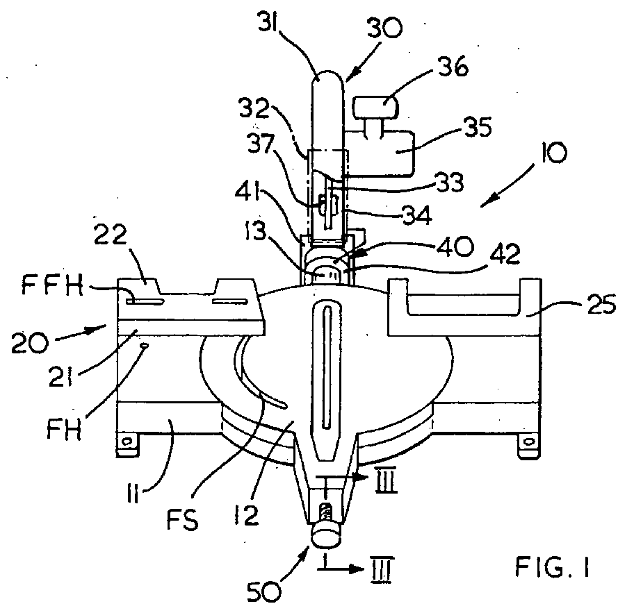
- FIG. 1 shows a power tool 10.
- the power tool 10 may be a chop saw, miter saw, compound miter saw, and/or sliding miter saw.
- miter saw 10 a power tool 10 shall be referred to herein as miter saw 10.
- Miter saw 10 comprises a base assembly 11, a table 12 rotatably attached to the base assembly, a saw assembly 30 pivotably attached to the table 12, and a fence assembly 20 fixedly attached to the base 11.
- the fence assembly 20 comprises a fixed fence 21 fixedly attached to the base assembly 11 and a slidable fence 22 slidably attached to the fixed fence 21.
- a second fence 25 may also be fixedly attached to base assembly 11.
- fixed fence 21, sliding fence 22 and/or a second fence 25 are co-planar.
- the table 12 may have a cylinder 13, which is pivotably connected to the trunnion junction 40.
- Trunnion junction 40 preferably includes a trunnion 41 which is pivotably attached to the table 12 in a manner well-known in the art. Such pivotal connection would enable a user to change the bevel angle of the miter saw 10.
- Saw assembly 30 is pivotably attached to table 12 via the trunnion junction 40 and cylinder 13. To enable a user to conduct the chopping operation, the saw assembly has an arm 34 which is pivotably attached to the trunnion 41.
- Saw assembly 30 may also include an upper blade guard 31 disposed on the arm 34, motor housing 35 for housing a motor (not shown), a handle 36 disposed on the motor housing 35 and/or upper blade guard 31 for allowing the user to move the saw assembly 30 downwardly, a blade 33 driven by the motor for cutting.
- the arm 34 may also include a dust collector 37 as is well known in the prior art. Persons skilled in the art are hereby referred to US Patent No. 5,819,619, which is wholly incorporated by reference herein.
- Saw assembly 30 may also include a lower blade guard for covering the lower portion of blade 33.
- base assembly 11 may have a circular well 11W for receiving a wear ring 14.
- the wear ring 14 may be disposed within a channel 11 C defined in well 11W by a wall 11WW.
- the wear ring 14 is not fixedly attached to base assembly 11.
- the wear ring is preferably sandwiched between base assembly 11 and table 12.
- wear ring 14 should be an appropriate material, such as steel, rubber or any equivalent thereof, that will enable rotation of table 12 on wear ring 14.
- wear ring 14 is L-shaped so that it can be inserted into channel 11C and support table 12 at the same time.
- the wear ring 14 is allowed to rotate as necessary while utilizing both contact sides for longer life.
- miter saw 10 with a miter lock mechanism 50.
- table 12 is rotatably attached to base assembly 11.
- a user can change the miter angle of the blade by rotating table 12 relative to base assembly 11.
- a miter lock mechanism is required.
- a simple screw/knob assembly allowed users to fix the rotational position of the table 12.
- Such mechanism did not prevent users from over-torquing the knob, thus causing damage to the miter lock mechanism, the table 12 and/or the base assembly 11.
- An improved miter lock mechanism 50 is disclosed herein.
- Miter lock mechanism 50 may include a screw 51 threadedly engaged through table 12 and contacting base assembly 11 in the locking position.
- a knob 53 is operatively connected to screw 51 for rotating screw 51.
- Miter lock mechanism 50 may also include a clutch mechanism 56 for preventing the user from over-torquing knob 53.
- the clutch mechanism 56 may include an auxiliary knob 52 fixedly attached to screw 51 for simultaneous rotation therewith.
- Auxiliary knob 52 may have teeth 54. Teeth 54 may engage extensions 55 disposed on knob 53.
- knob 53 preferably has extensions 55 which are resiliently connected to the knob 53 and are moveable between first position contacting teeth 54, and a second position bypassing teeth 54.
- Extension 55 may include a ramp 55R which moves along tooth 54 in the first position.
- tooth 54, extension 55, and/or ramp 55 will be designed in order to meet the desired torque requirements.
- Extension 55 may have a latching area 55L, which is preferably located on the rear side of the ramp 55R. With such arrangement, when the user rotates the knob 53 for unlocking the miter lock, the latch area 55L will latch onto tooth 54, causing the knob 53 and auxiliary 52 to rotate together.
- the actual shape of the latching area 55L and tooth 54 should be designed so as to minimize the movement of extension 55 between the first and second positions.
- the miter saw 10 may be provided with means for mounting fixtures thereon.
- Fixture F may be attached on the miter saw 10 for supporting a workpiece W disposed on table 12 and/or base assembly 11.
- Fence assembly 20 may be provided with a hole FFH.
- Hole FFH may be either round or a slot, and should be of such size to allow the user to put a screw FFB therethrough.
- the hole size will allow a number 8 screw therethrough.
- the hole FFH may have a diameter of about 3/16 of an inch.
- hole FFH is provided on the sliding fence 21, thus providing the user with moveable fixture F. Accordingly, the fence assembly 20 can be converted into a movable end stop, allowing the end user to move the workpiece W to a first desired position, then adjusting the sliding fence 22 to a second desired position, and moving the workpiece W to that second desired position.
- FIGS. 1 and 15 illustrate a different fixture mount.
- the fixture F is preferably mounted to base assembly 11 and/or table 12 via bolts FB extending through the fixture F.
- Bolt FB may screw onto base assembly 11 and/or table 12 directly or into nuts F disposed underneath the base assembly 11 and/or rotatable table 12.
- Bolt FB may extend through hole FH in base assembly 11 or through slot FS on table 12. Having a slot FS allow the user to move table 12 without removing bolt FB or fixture F.
- fixture mounting holes FH, FFH and/or FS can be cast or machined into the different pieces.
- miter saw 10 may be provided with a bevel scale mechanism 60.
- Bevel scale mechanism 60 may be used to indicate the bevel angle of miter saw 10.
- Bevel scale mechanism 60 may include scale 62 on trunnion 41, and pointer 61 disposed on cylinder 13. Persons skilled in the art should recognize that scale 60 may be disposed on cylinder 13 and pointer 61 may be disposed on trunnion 41.
- Scale 62 may have indicia 62 I thereon to better denote the bevel angle.
- adjustable pointer 61 may include fixed portion 61 F and an adjustable portion 61A removeably disposed on fixed portion 61 F. Screw 61 S may fix the location of adjustable portion 61A relative to fixed portion 61S. The bevel pointer 61 may then be attached to cylinder 13 via screw 63.
- Screw 61 S may be threadedly extend through slots 61 N in adjustable portion 61A. Screw 61S may threadedly engage a nut (not shown) disposed behind fixed portion 61 F or may be threadedly engaged into fixed portion 61 F.
- pointer 61 By connecting pointer 61 to cylinder 13 via screw 63, pointer 61 is thus adjustable via rotation about the longitudinal axis of screw 63 and/or moveable in a direction parallel to the longitudinal axis of screw 63.
- FIGS. 9A and 9B A second adjustable pointer 65 is shown in FIGS. 9A and 9B.
- pointer 65 is again attached to cylinder 13 via a screw 66 which preferably extends through pointer 65 and protrusion 13P of cylinder 13. Screw 66 may be threadedly engaged to a nut 68 behind the protrusion 13P.
- the pointer 65 may be adjusted relative to the scale 62 by inserting washers 67 between pointer 65 and protrusion 13P. It may be preferable to provide a fixed number of washers so that the user may put some between screw 66 and pointer 65 and the remainder between pointer 65 and protrusion 13P.
- upper blade guard 31 may have a pivot plate 70 pivotally attached to upper blade guard 31 via bolt 71 for rotatably supporting lower blade guard 32.
- Pivot plate 70 may be locked in a fixed position relative to upper blade guard 31 via bolt 73.
- Pivot plate 70 may also cover arbor A and must be pivoted in order to provide access to arbor A. To do so, the user needs to unscrew screw 73 so that it bypasses tab 71A. Once the screw 73 can bypass tab 71A, screw 73 will slide along slot 72.
- slot 72 may be closed slot as shown in FIG. 10 or an open slot so that the user can completely separate the pivot plate 70 and screw 73.
- screw 73 is preferably threadedly engaged to upper blade guard 31.
- Pivot plate 70 may also have a tab 74 extending inwardly toward blade 33.
- Tab 74 extends inwardly so that it can contact upper blade guard 31 when the pivot plate 70 is pivoted. In other words, tab 74 limits the range of movement of pivot plate 70.
- pivot plate 70 may have channel tab 75, which preferably extends inwardly towards and parallel to blade 33.
- Upper blade guard 31 may extend between pivot plate 70 and channel tab 75. Such arrangement prevents pivot plate 70 from moving laterally excessively.
- pivot plate 70 may also have blade caliper tab 76.
- Blade caliper tab 76 extends inwardly towards blade 33.
- tab 76 extends within several millimeters of blade 33. With such arrangement, tab 76 prevents blade 33 from moving laterally excessively during the rotation thereof, and from cutting upper blade guard 31.
- FIG. 16 illustrates the connection between pivot plate 70 and lower blade guard 32.
- a rotational spring 77 is captured between pivot plate 70 and lower blade guard 32.
- one end of spring 77 is shaped like a hook 77H.
- hook 77H is inserted through slot 32S and then released during assembly. Hook 77H will then move towards the end of slot 32S providing a durable junction that is easy to assemble.
- spring 77 may also be shaped as a hook and inserted through pivot plate 70.
- the other end of spring 77 is shaped like a bent leg 77L, which then may be inserted through slot 70S in pivot plate 70.
- pivot plate 70 is connected to lower blade guard 32 via a screw 38.
- Screw 38 may be inserted through lower blade guard 32 and threadingly engage pivot plate 70.
- screw 38 may be inserted through pivot plate 70 and lower blade guard 32 and threadingly engaged to a plate retainer 78.
- a portion of plate retainer 78 extends through lower blade guard 32 and/or contact pivot plate 70.
Abstract
Description
- The invention relates to miter saws.
- Miter saws are power tools typically comprising a base assembly, a table rotatably attached to the base assembly (for allowing the user to change the miter angle) and a saw assembly pivotably attached to the table so that the saw assembly can move downwardly for cutting. The saw assembly typically includes a blade and a motor driving the blade.
- It is well known in the art to provide a wear ring between the base assembly and the table to minimize binding and friction therebetween.
- Usually the wear ring consists of a metal ring disposed between the table and the base assembly. Typically this metal ring is bolted down onto the base assembly or the table so that the wear ring does not rotate.
- It is an object of the invention to provide a miter saw with a better wear system. In accordance with the present invention, an improved miter saw is disclosed. An improved miter saw comprises a base assembly, a table rotatably attached to the base assembly, a saw assembly pivotably attached to the table, a wear ring non-fixedly attached between the base assembly and the table and wear ring. Other inventions are described herein.
- Additional features and benefits of the present invention are described, and will be apparent from the accompanying drawings and detailed description below.
- The accompanying drawings illustrate preferred embodiments of the invention according to the practical application of the principles thereof, and in which:
- FIG. 1 is an elevated front perspective view of a miter saw according to the invention;
- FIG. 2 is an exploded view of the base assembly;
- FIG. 3 is a cross-sectional view of the improved miter lock mechanism of FIG. 1, along line III-III as shown in FIG. 1;
- FIG. 4 is a partial cross-sectional view of the miter lock mechanism of FIG. 3, along line IV-IV as shown in FIG. 3;
- FIG 5 is partial cross-sectional view of the miter lock mechanism where FIG. 5A and 5B show different operational positions of the miter lock mechanism.
- FIG. 6 is a partial front view of the bevel scale mechanism according to the invention.
- FIG. 7 is side view of the bevel scale mechanism of FIG. 6;
- FIG. 8 is a close up view of the pointer of FIG. 6 and 7;
- FIG. 9 illustrates a second embodiment of the bevel scale mechanism according to the invention, where FIG. 9A and 9B show different positions of the pointer;
- FIG. 10 is a partial side view of the upper blade guard and pivot blade according to the present invention;
- FIG. 11 is a partial cross-sectional view of along line XI-XI as shown in FIG. 10;
- FIG. 12 is a partial cross-sectional view along line XII-XII as shown in FIG. 10;
- FIG. 13 is a partial cross-sectional view along line XIII-XIII as shown in FIG. 10;
- FIG. 14 illustrates a first fixture mount according to the invention;
- FIG. 15 illustrates a second fixture mount according to the invention; and
- FIG. 16 is a partial cross-sectional view of the pivot plate/lower blade guard assembly.
-
- The invention is now described with reference to the accompanying figures, wherein like numerals designate like parts. FIG. 1 shows a
power tool 10. Persons skilled in the art should recognize that thepower tool 10 may be a chop saw, miter saw, compound miter saw, and/or sliding miter saw. For the purpose of clarity, apower tool 10 shall be referred to herein as miter saw 10. - Miter saw 10 comprises a
base assembly 11, a table 12 rotatably attached to the base assembly, asaw assembly 30 pivotably attached to the table 12, and afence assembly 20 fixedly attached to thebase 11. Preferably, thefence assembly 20 comprises afixed fence 21 fixedly attached to thebase assembly 11 and aslidable fence 22 slidably attached to thefixed fence 21. Persons skilled in the art are hereby referred to US Patent No. 5,297,463, which is hereby wholly incorporated by reference. Asecond fence 25 may also be fixedly attached tobase assembly 11. Preferably fixedfence 21, slidingfence 22 and/or asecond fence 25 are co-planar. - The table 12 may have a
cylinder 13, which is pivotably connected to thetrunnion junction 40. Trunnionjunction 40 preferably includes atrunnion 41 which is pivotably attached to the table 12 in a manner well-known in the art. Such pivotal connection would enable a user to change the bevel angle of the miter saw 10. -
Saw assembly 30 is pivotably attached to table 12 via thetrunnion junction 40 andcylinder 13. To enable a user to conduct the chopping operation, the saw assembly has anarm 34 which is pivotably attached to thetrunnion 41. -
Saw assembly 30 may also include anupper blade guard 31 disposed on thearm 34,motor housing 35 for housing a motor (not shown), ahandle 36 disposed on themotor housing 35 and/orupper blade guard 31 for allowing the user to move thesaw assembly 30 downwardly, ablade 33 driven by the motor for cutting. Thearm 34 may also include adust collector 37 as is well known in the prior art. Persons skilled in the art are hereby referred to US Patent No. 5,819,619, which is wholly incorporated by reference herein. -
Saw assembly 30 may also include a lower blade guard for covering the lower portion ofblade 33. - As mentioned above, the table 12 is rotatably connected to
base assembly 11. Referring to FIGS. 1 and 2,base assembly 11 may have a circular well 11W for receiving awear ring 14. Thewear ring 14 may be disposed within a channel 11 C defined in well 11W by a wall 11WW. Thewear ring 14 is not fixedly attached tobase assembly 11. The wear ring is preferably sandwiched betweenbase assembly 11 and table 12. - Persons skilled in the art will recognize that the composition of
wear ring 14 should be an appropriate material, such as steel, rubber or any equivalent thereof, that will enable rotation of table 12 onwear ring 14. Preferably wearring 14 is L-shaped so that it can be inserted into channel 11C and support table 12 at the same time. - Because the ring is not fixedly attached to
base assembly 11 or to table 12, thewear ring 14 is allowed to rotate as necessary while utilizing both contact sides for longer life. - Referring to FIGS. 1 and 3-5, it is preferable to provide
miter saw 10 with amiter lock mechanism 50. As mentioned above, table 12 is rotatably attached tobase assembly 11. A user can change the miter angle of the blade by rotating table 12 relative tobase assembly 11. In order to lock the rotational position of table 12, a miter lock mechanism is required. In the prior art, a simple screw/knob assembly allowed users to fix the rotational position of the table 12. However, such mechanism did not prevent users from over-torquing the knob, thus causing damage to the miter lock mechanism, the table 12 and/or thebase assembly 11. An improvedmiter lock mechanism 50 is disclosed herein. -
Miter lock mechanism 50 may include ascrew 51 threadedly engaged through table 12 and contactingbase assembly 11 in the locking position. Aknob 53 is operatively connected toscrew 51 for rotatingscrew 51.Miter lock mechanism 50 may also include aclutch mechanism 56 for preventing the user fromover-torquing knob 53. Theclutch mechanism 56 may include anauxiliary knob 52 fixedly attached to screw 51 for simultaneous rotation therewith.Auxiliary knob 52 may haveteeth 54.Teeth 54 may engageextensions 55 disposed onknob 53. - As shown in further detail on FIGS. 4 and 5,
knob 53 preferably hasextensions 55 which are resiliently connected to theknob 53 and are moveable between firstposition contacting teeth 54, and a secondposition bypassing teeth 54.Extension 55 may include aramp 55R which moves alongtooth 54 in the first position. Persons of ordinary skill in the art will recognize that the shape and form oftooth 54,extension 55, and/orramp 55 will be designed in order to meet the desired torque requirements. - Persons skilled in the art will also recognize that, as the user rotates
knob 53, theprotrusion 55 will cause rotation ofauxiliary knob 54 unless a predetermined torque limit is reached, upon whichextension 55 will slide alongtooth 54 until it moves to the second position whereextension 55bypasses tooth 54. -
Extension 55 may have alatching area 55L, which is preferably located on the rear side of theramp 55R. With such arrangement, when the user rotates theknob 53 for unlocking the miter lock, thelatch area 55L will latch ontotooth 54, causing theknob 53 and auxiliary 52 to rotate together. Persons skilled in the art shall recognize that the actual shape of the latchingarea 55L andtooth 54 should be designed so as to minimize the movement ofextension 55 between the first and second positions. - Persons or ordinary skill in the arts should also recognize that the
extensions 55 andtooth 54 may be provided on theauxiliary knob 52, andknob 53, respectively, in order to achieve the same results. - Referring to FIG. 14, the miter saw 10 may be provided with means for mounting fixtures thereon. Fixture F may be attached on the miter saw 10 for supporting a workpiece W disposed on table 12 and/or
base assembly 11.Fence assembly 20 may be provided with a hole FFH. Hole FFH may be either round or a slot, and should be of such size to allow the user to put a screw FFB therethrough. Preferably, the hole size will allow a number 8 screw therethrough. In other words, the hole FFH may have a diameter of about 3/16 of an inch. - Preferably, hole FFH is provided on the sliding
fence 21, thus providing the user with moveable fixture F. Accordingly, thefence assembly 20 can be converted into a movable end stop, allowing the end user to move the workpiece W to a first desired position, then adjusting the slidingfence 22 to a second desired position, and moving the workpiece W to that second desired position. - FIGS. 1 and 15 illustrate a different fixture mount. In miter saw 10, the fixture F is preferably mounted to
base assembly 11 and/or table 12 via bolts FB extending through the fixture F. Bolt FB may screw ontobase assembly 11 and/or table 12 directly or into nuts F disposed underneath thebase assembly 11 and/or rotatable table 12. Persons skilled in the art should recognize that bolt FB may extend through hole FH inbase assembly 11 or through slot FS on table 12. Having a slot FS allow the user to move table 12 without removing bolt FB or fixture F. - Persons skilled in the art shall recognize that the fixture mounting holes FH, FFH and/or FS can be cast or machined into the different pieces.
- Referring to FIG. 6, miter saw 10 may be provided with a
bevel scale mechanism 60.Bevel scale mechanism 60 may be used to indicate the bevel angle of miter saw 10.Bevel scale mechanism 60 may includescale 62 ontrunnion 41, andpointer 61 disposed oncylinder 13. Persons skilled in the art should recognize thatscale 60 may be disposed oncylinder 13 andpointer 61 may be disposed ontrunnion 41.Scale 62 may haveindicia 62 I thereon to better denote the bevel angle. - It may be preferable to provide an
adjustable pointer 61 to adjust the pointer close to thescale 62 without contacting thescale 62. Referring to FIGS. 6-8,adjustable bevel pointer 61 may include fixedportion 61 F and anadjustable portion 61A removeably disposed on fixedportion 61 F. Screw 61 S may fix the location ofadjustable portion 61A relative to fixed portion 61S. Thebevel pointer 61 may then be attached tocylinder 13 viascrew 63. - Screw 61 S may be threadedly extend through slots 61 N in
adjustable portion 61A. Screw 61S may threadedly engage a nut (not shown) disposed behind fixedportion 61 F or may be threadedly engaged into fixedportion 61 F. - By connecting
pointer 61 tocylinder 13 viascrew 63,pointer 61 is thus adjustable via rotation about the longitudinal axis ofscrew 63 and/or moveable in a direction parallel to the longitudinal axis ofscrew 63. - A second
adjustable pointer 65 is shown in FIGS. 9A and 9B. The teachings of the previous embodiments are wholly incorporated by reference, where like numerals refer to like parts. In this embodiment,pointer 65 is again attached tocylinder 13 via ascrew 66 which preferably extends throughpointer 65 andprotrusion 13P ofcylinder 13.Screw 66 may be threadedly engaged to anut 68 behind theprotrusion 13P. Thepointer 65 may be adjusted relative to thescale 62 by insertingwashers 67 betweenpointer 65 andprotrusion 13P. It may be preferable to provide a fixed number of washers so that the user may put some betweenscrew 66 andpointer 65 and the remainder betweenpointer 65 andprotrusion 13P. - Referring to FIGS. 10-11,
upper blade guard 31 may have apivot plate 70 pivotally attached toupper blade guard 31 viabolt 71 for rotatably supportinglower blade guard 32.Pivot plate 70 may be locked in a fixed position relative toupper blade guard 31 viabolt 73.Pivot plate 70 may also cover arbor A and must be pivoted in order to provide access to arbor A. To do so, the user needs to unscrewscrew 73 so that it bypassestab 71A. Once thescrew 73 can bypasstab 71A, screw 73 will slide alongslot 72. Persons skilled in the art will recognize thatslot 72 may be closed slot as shown in FIG. 10 or an open slot so that the user can completely separate thepivot plate 70 andscrew 73. Persons skilled in the art will also recognize thatscrew 73 is preferably threadedly engaged toupper blade guard 31. - Referring to FIGS. 11A-11B, persons skilled in the art should recognize that when the head of the
screw 73 is moved to bypasstab 71A, such position will block movement oflower blade guard 32. Accordingly, if a user wants to lowerblade guard 32, the user will have to putpivot plate 70 in its original position and screw 73 thereon. -
Pivot plate 70 may also have atab 74 extending inwardly towardblade 33.Tab 74 extends inwardly so that it can contactupper blade guard 31 when thepivot plate 70 is pivoted. In other words,tab 74 limits the range of movement ofpivot plate 70. - Referring to FIGS. 10 and 12,
pivot plate 70 may havechannel tab 75, which preferably extends inwardly towards and parallel toblade 33.Upper blade guard 31 may extend betweenpivot plate 70 andchannel tab 75. Such arrangement preventspivot plate 70 from moving laterally excessively. - Referring to FIGS. 10 and 13,
pivot plate 70 may also haveblade caliper tab 76.Blade caliper tab 76 extends inwardly towardsblade 33. Preferably,tab 76 extends within several millimeters ofblade 33. With such arrangement,tab 76 preventsblade 33 from moving laterally excessively during the rotation thereof, and from cuttingupper blade guard 31. - FIG. 16 illustrates the connection between
pivot plate 70 andlower blade guard 32. Preferably, arotational spring 77 is captured betweenpivot plate 70 andlower blade guard 32. Preferably, one end ofspring 77 is shaped like ahook 77H. Preferably,hook 77H is inserted through slot 32S and then released during assembly.Hook 77H will then move towards the end of slot 32S providing a durable junction that is easy to assemble. - Similarly, the other end of
spring 77 may also be shaped as a hook and inserted throughpivot plate 70. Alternatively, the other end ofspring 77 is shaped like abent leg 77L, which then may be inserted throughslot 70S inpivot plate 70. - Preferably,
pivot plate 70 is connected tolower blade guard 32 via ascrew 38.Screw 38 may be inserted throughlower blade guard 32 and threadingly engagepivot plate 70. Alternatively, screw 38 may be inserted throughpivot plate 70 andlower blade guard 32 and threadingly engaged to aplate retainer 78. Preferably, a portion ofplate retainer 78 extends throughlower blade guard 32 and/orcontact pivot plate 70. - Persons skilled in the art may recognize other alternatives to the means disclosed herein. However, all these additions and/or alterations are considered to be equal inside the present invention.
Claims (8)
- A miter saw comprising:a base assembly;a table rotatably attached to the base assembly;a saw assembly pivotably attached to the table;a fixed fence attached to the base assembly; anda sliding fence slidably attached to the fixed fence, the sliding fence having at least one hole for fixing an end stop fixture thereto.
- The miter saw of Claim 1, wherein the hole is about 3/16 of an inch.
- A miter saw comprising:wherein at least one of the base assembly and the table has at least one hole for fixing a fixture thereto.a base assembly;a table rotatably attached to the base assembly; and
- The miter saw of Claim 3, wherein the hole is about 3/16 of an inch.
- A chop saw comprising:wherein at least one of the upper blade guard and plate have a first tab extending outwardly a first distance near the screw, the screw being required to be moved a second distance longer than the first distance in order to pivot the plate, the second distance being longer than distance between the lower blade guard and the upper blade guard.a base assembly; anda saw assembly pivotably attached to the base assembly, the saw assembly comprising an upper blade guard, a plate rotatably attached to the upper blade guard, a lower blade guard rotatably attached to the plate, and a screw engaging the upper blade guard for fixing the plate;
- The chop saw of Claim 5, wherein the plate has a second tab extending inwardly which contacts the upper blade guard upon pivoting of the plate.
- The chop saw of Claim 5, wherein the plate has a second tab extending inwardly and defining a channel, the upper blade guard extending into the channel.
- The chop saw of Claim 5, wherein the plate has a second tab extending inwardly towards a blade.
Priority Applications (1)
| Application Number | Priority Date | Filing Date | Title |
|---|---|---|---|
| EP07108525A EP1815929B1 (en) | 2001-02-01 | 2002-01-30 | Miter saw |
Applications Claiming Priority (5)
| Application Number | Priority Date | Filing Date | Title |
|---|---|---|---|
| US26556701P | 2001-02-01 | 2001-02-01 | |
| US265567P | 2001-02-01 | ||
| US10/054,257 US7617755B2 (en) | 2001-02-01 | 2002-01-22 | Miter saw |
| US54257 | 2002-01-22 | ||
| EP20020250630 EP1231006B1 (en) | 2001-02-01 | 2002-01-30 | Miter saw |
Related Parent Applications (1)
| Application Number | Title | Priority Date | Filing Date |
|---|---|---|---|
| EP20020250630 Division EP1231006B1 (en) | 2001-02-01 | 2002-01-30 | Miter saw |
Related Child Applications (1)
| Application Number | Title | Priority Date | Filing Date |
|---|---|---|---|
| EP07108525A Division EP1815929B1 (en) | 2001-02-01 | 2002-01-30 | Miter saw |
Publications (3)
| Publication Number | Publication Date |
|---|---|
| EP1568432A2 true EP1568432A2 (en) | 2005-08-31 |
| EP1568432A3 EP1568432A3 (en) | 2005-12-21 |
| EP1568432B1 EP1568432B1 (en) | 2007-09-05 |
Family
ID=26732804
Family Applications (2)
| Application Number | Title | Priority Date | Filing Date |
|---|---|---|---|
| EP20020250630 Expired - Lifetime EP1231006B1 (en) | 2001-02-01 | 2002-01-30 | Miter saw |
| EP20050010595 Expired - Lifetime EP1568432B1 (en) | 2001-02-01 | 2002-01-30 | Miter saw |
Family Applications Before (1)
| Application Number | Title | Priority Date | Filing Date |
|---|---|---|---|
| EP20020250630 Expired - Lifetime EP1231006B1 (en) | 2001-02-01 | 2002-01-30 | Miter saw |
Country Status (3)
| Country | Link |
|---|---|
| US (2) | US7617755B2 (en) |
| EP (2) | EP1231006B1 (en) |
| DE (2) | DE60210218T2 (en) |
Families Citing this family (14)
| Publication number | Priority date | Publication date | Assignee | Title |
|---|---|---|---|---|
| US7243587B2 (en) * | 2002-12-16 | 2007-07-17 | Black & Decker Inc. | Pivoting rear blade guard |
| US9027450B1 (en) * | 2003-01-21 | 2015-05-12 | Roland Santa Ana | Work piece cutting apparatus |
| CA2422984A1 (en) * | 2003-03-20 | 2004-09-20 | Claude Auger | Method and apparatus for reducing damage to a circular saw blade on a delimbing machine |
| DE602005006904D1 (en) * | 2004-07-07 | 2008-07-03 | Black & Decker Inc | Stop for miter saws |
| TWI341781B (en) * | 2004-09-03 | 2011-05-11 | Black & Decker Inc | Trunnion assembly for saws |
| US20060249000A1 (en) * | 2005-05-03 | 2006-11-09 | Meredith Daryl S | Miter assembly for miter saws |
| TW200812766A (en) * | 2006-09-01 | 2008-03-16 | P & F Brother Ind Corp | Fastening device of blocking sheet for cutting machine |
| US20090301277A1 (en) * | 2008-06-09 | 2009-12-10 | Aleksander Ipatenco | Saw With Moveable Material Support Surface |
| CN101745689B (en) * | 2008-12-18 | 2012-12-19 | 苏州宝时得电动工具有限公司 | Oblique saw |
| JP5313081B2 (en) * | 2009-08-20 | 2013-10-09 | 株式会社マキタ | Inclination positioning mechanism of cutting machine body in tabletop cutting machine |
| CN102615345B (en) * | 2011-01-30 | 2014-04-16 | 苏州宝时得电动工具有限公司 | Cutting machine |
| US8850940B2 (en) | 2011-06-07 | 2014-10-07 | Robert Bosch Gmbh | Integrated stand mount for miter saw |
| WO2016138281A1 (en) | 2015-02-25 | 2016-09-01 | Milwaukee Electric Tool Corporation | Miter saw |
| MX2019006805A (en) | 2018-06-12 | 2019-12-13 | Tti Macao Commercial Offshore Ltd | Miter saw. |
Citations (1)
| Publication number | Priority date | Publication date | Assignee | Title |
|---|---|---|---|---|
| US5297463A (en) * | 1991-10-09 | 1994-03-29 | Black & Decker Inc. | Adjustable fence for compound miter saw |
Family Cites Families (14)
| Publication number | Priority date | Publication date | Assignee | Title |
|---|---|---|---|---|
| US3998121A (en) | 1976-02-03 | 1976-12-21 | B & E Products, Inc. | Miter cutting saw |
| US4226151A (en) * | 1979-03-29 | 1980-10-07 | Cincinnati Incorporated | Slitter having arbor pairs mounted on a caster supported base shiftable and orientable along the slitter frame |
| JP2717534B2 (en) * | 1986-12-29 | 1998-02-18 | 株式会社マキタ | Safety cover device for circular saw machine |
| US4934233B1 (en) * | 1988-06-29 | 1994-08-23 | Emerson Electric Co | Compound miter saw |
| US5181448A (en) * | 1991-12-20 | 1993-01-26 | Emerson Electric Co. | Miter saw apparatus with adjustable workpiece supporting fence |
| CA2148974A1 (en) * | 1994-05-13 | 1995-11-14 | Richard P. Brault | Turntable mechanism for a cutting tool |
| US5595124A (en) | 1994-06-08 | 1997-01-21 | Delta International Machinery Corp. | Restraining mechanism |
| US5755148A (en) * | 1995-07-07 | 1998-05-26 | Black & Decker Inc. | Adjustable fence for a compound miter saw |
| US5957021A (en) * | 1995-10-10 | 1999-09-28 | Black & Decker, Inc. | Guard and control apparatuses for sliding compound miter saw |
| US6474206B1 (en) * | 1995-12-12 | 2002-11-05 | Black & Decker Inc. | Miter saw with wear plates and orientation system therefor |
| US5778747A (en) * | 1996-11-21 | 1998-07-14 | Rexon Industrial Corp., Ltd. | Power saw having an ergonomically-designed handle and safety switch |
| US5950514A (en) * | 1997-02-28 | 1999-09-14 | Benedict Engineering Company | Miter saw blade guards |
| US5855366A (en) * | 1997-10-29 | 1999-01-05 | P & F Brother Industrial Corporation | Work supporting device mountable on a worktable of a circular sawing apparatus |
| US6279442B1 (en) * | 1998-09-11 | 2001-08-28 | Chin-Chin Chang | Blade guard device for a sawing machine |
-
2002
- 2002-01-22 US US10/054,257 patent/US7617755B2/en not_active Expired - Fee Related
- 2002-01-30 DE DE2002610218 patent/DE60210218T2/en not_active Expired - Lifetime
- 2002-01-30 DE DE2002622309 patent/DE60222309T2/en not_active Expired - Lifetime
- 2002-01-30 EP EP20020250630 patent/EP1231006B1/en not_active Expired - Lifetime
- 2002-01-30 EP EP20050010595 patent/EP1568432B1/en not_active Expired - Lifetime
-
2009
- 2009-10-15 US US12/579,489 patent/US20100050842A1/en not_active Abandoned
Patent Citations (1)
| Publication number | Priority date | Publication date | Assignee | Title |
|---|---|---|---|---|
| US5297463A (en) * | 1991-10-09 | 1994-03-29 | Black & Decker Inc. | Adjustable fence for compound miter saw |
Also Published As
| Publication number | Publication date |
|---|---|
| EP1231006B1 (en) | 2006-03-29 |
| US20100050842A1 (en) | 2010-03-04 |
| US7617755B2 (en) | 2009-11-17 |
| EP1568432B1 (en) | 2007-09-05 |
| EP1231006A3 (en) | 2003-11-19 |
| EP1568432A3 (en) | 2005-12-21 |
| DE60222309T2 (en) | 2008-05-29 |
| DE60210218T2 (en) | 2007-03-08 |
| EP1231006A2 (en) | 2002-08-14 |
| US20020100351A1 (en) | 2002-08-01 |
| DE60210218D1 (en) | 2006-05-18 |
| DE60222309D1 (en) | 2007-10-18 |
Similar Documents
| Publication | Publication Date | Title |
|---|---|---|
| US20100050842A1 (en) | Miter Saw | |
| US6990883B2 (en) | Bevel locking system for a sliding compound miter saw | |
| EP1256407B1 (en) | Compound miter saw comprising a table with a detent system and a locking system | |
| EP0860250B1 (en) | Bevel locking system for a sliding compound miter saw | |
| US6606931B1 (en) | Bevel locking system for a sliding compound miter saw | |
| EP0779122B1 (en) | Rotatable worktable | |
| US7806032B2 (en) | Table saw guard system side barrier | |
| US6758123B2 (en) | Bevel angle detent system for a compound miter saw | |
| CA2544212A1 (en) | Bevel lock assembly for miter saws | |
| EP1621302A1 (en) | Fence assembly for miter saws | |
| US8511211B2 (en) | Power miter saw having adjustable lower guard operating mechanism | |
| US7013781B2 (en) | Bevel locking system for a sliding compound miter saw | |
| US6032562A (en) | Bevel locking system for a sliding compound miter saw | |
| EP1815929B1 (en) | Miter saw | |
| JP2002254238A (en) | Fence assembly for combined circular saw | |
| EP1818144B1 (en) | Bevel lock assembly for miter saws |
Legal Events
| Date | Code | Title | Description |
|---|---|---|---|
| PUAI | Public reference made under article 153(3) epc to a published international application that has entered the european phase |
Free format text: ORIGINAL CODE: 0009012 |
|
| 17P | Request for examination filed |
Effective date: 20050517 |
|
| AC | Divisional application: reference to earlier application |
Ref document number: 1231006 Country of ref document: EP Kind code of ref document: P |
|
| AK | Designated contracting states |
Kind code of ref document: A2 Designated state(s): DE FR GB IT |
|
| PUAL | Search report despatched |
Free format text: ORIGINAL CODE: 0009013 |
|
| RIN1 | Information on inventor provided before grant (corrected) |
Inventor name: OKTAVEC, CRAIG A. Inventor name: SHEDDY, GREGG L. Inventor name: WELSH, ROBERT P. Inventor name: AYALA, ADAN Inventor name: BRUNSON, MARK E. Inventor name: CHAIKOWSKY, PETER Inventor name: PARKS, JAMES R. Inventor name: BEAN, FREDERICK R. |
|
| AK | Designated contracting states |
Kind code of ref document: A3 Designated state(s): DE FR GB IT |
|
| 17Q | First examination report despatched |
Effective date: 20060620 |
|
| AKX | Designation fees paid |
Designated state(s): DE FR GB IT |
|
| GRAP | Despatch of communication of intention to grant a patent |
Free format text: ORIGINAL CODE: EPIDOSNIGR1 |
|
| GRAS | Grant fee paid |
Free format text: ORIGINAL CODE: EPIDOSNIGR3 |
|
| GRAA | (expected) grant |
Free format text: ORIGINAL CODE: 0009210 |
|
| AC | Divisional application: reference to earlier application |
Ref document number: 1231006 Country of ref document: EP Kind code of ref document: P |
|
| AK | Designated contracting states |
Kind code of ref document: B1 Designated state(s): DE FR GB IT |
|
| REG | Reference to a national code |
Ref country code: GB Ref legal event code: FG4D |
|
| REF | Corresponds to: |
Ref document number: 60222309 Country of ref document: DE Date of ref document: 20071018 Kind code of ref document: P |
|
| ET | Fr: translation filed | ||
| PLBE | No opposition filed within time limit |
Free format text: ORIGINAL CODE: 0009261 |
|
| STAA | Information on the status of an ep patent application or granted ep patent |
Free format text: STATUS: NO OPPOSITION FILED WITHIN TIME LIMIT |
|
| 26N | No opposition filed |
Effective date: 20080606 |
|
| PGFP | Annual fee paid to national office [announced via postgrant information from national office to epo] |
Ref country code: FR Payment date: 20090119 Year of fee payment: 8 |
|
| REG | Reference to a national code |
Ref country code: FR Ref legal event code: ST Effective date: 20100930 |
|
| PG25 | Lapsed in a contracting state [announced via postgrant information from national office to epo] |
Ref country code: FR Free format text: LAPSE BECAUSE OF NON-PAYMENT OF DUE FEES Effective date: 20100201 |
|
| PGFP | Annual fee paid to national office [announced via postgrant information from national office to epo] |
Ref country code: IT Payment date: 20120123 Year of fee payment: 11 |
|
| PGFP | Annual fee paid to national office [announced via postgrant information from national office to epo] |
Ref country code: GB Payment date: 20130125 Year of fee payment: 12 Ref country code: DE Payment date: 20130129 Year of fee payment: 12 |
|
| REG | Reference to a national code |
Ref country code: DE Ref legal event code: R119 Ref document number: 60222309 Country of ref document: DE |
|
| GBPC | Gb: european patent ceased through non-payment of renewal fee |
Effective date: 20140130 |
|
| PG25 | Lapsed in a contracting state [announced via postgrant information from national office to epo] |
Ref country code: DE Free format text: LAPSE BECAUSE OF NON-PAYMENT OF DUE FEES Effective date: 20140801 |
|
| REG | Reference to a national code |
Ref country code: DE Ref legal event code: R119 Ref document number: 60222309 Country of ref document: DE Effective date: 20140801 |
|
| PG25 | Lapsed in a contracting state [announced via postgrant information from national office to epo] |
Ref country code: GB Free format text: LAPSE BECAUSE OF NON-PAYMENT OF DUE FEES Effective date: 20140130 |
|
| PG25 | Lapsed in a contracting state [announced via postgrant information from national office to epo] |
Ref country code: IT Free format text: LAPSE BECAUSE OF NON-PAYMENT OF DUE FEES Effective date: 20140130 |