EP1570246B1 - Thermal tympanic thermometer tip - Google Patents
Thermal tympanic thermometer tip Download PDFInfo
- Publication number
- EP1570246B1 EP1570246B1 EP03721680A EP03721680A EP1570246B1 EP 1570246 B1 EP1570246 B1 EP 1570246B1 EP 03721680 A EP03721680 A EP 03721680A EP 03721680 A EP03721680 A EP 03721680A EP 1570246 B1 EP1570246 B1 EP 1570246B1
- Authority
- EP
- European Patent Office
- Prior art keywords
- sensor
- tympanic thermometer
- nozzle
- temperature
- thermometer according
- Prior art date
- Legal status (The legal status is an assumption and is not a legal conclusion. Google has not performed a legal analysis and makes no representation as to the accuracy of the status listed.)
- Expired - Lifetime
Links
- 239000000523 sample Substances 0.000 claims abstract description 65
- 239000011810 insulating material Substances 0.000 claims abstract 2
- 239000000463 material Substances 0.000 claims description 11
- 230000005855 radiation Effects 0.000 claims description 8
- 229910001092 metal group alloy Inorganic materials 0.000 claims description 2
- 230000004907 flux Effects 0.000 abstract description 10
- 238000000034 method Methods 0.000 abstract description 5
- 210000003454 tympanic membrane Anatomy 0.000 description 14
- 238000009529 body temperature measurement Methods 0.000 description 11
- 230000036760 body temperature Effects 0.000 description 9
- 238000012546 transfer Methods 0.000 description 9
- 238000009826 distribution Methods 0.000 description 5
- 230000008859 change Effects 0.000 description 4
- 238000013461 design Methods 0.000 description 4
- 239000011521 glass Substances 0.000 description 4
- 239000012528 membrane Substances 0.000 description 4
- 239000004033 plastic Substances 0.000 description 4
- 229920003023 plastic Polymers 0.000 description 4
- 201000010099 disease Diseases 0.000 description 3
- 208000037265 diseases, disorders, signs and symptoms Diseases 0.000 description 3
- 210000000613 ear canal Anatomy 0.000 description 3
- -1 for example Substances 0.000 description 3
- 230000009467 reduction Effects 0.000 description 3
- 230000001052 transient effect Effects 0.000 description 3
- 241000894006 Bacteria Species 0.000 description 2
- 206010050337 Cerumen impaction Diseases 0.000 description 2
- 241001465754 Metazoa Species 0.000 description 2
- 206010037660 Pyrexia Diseases 0.000 description 2
- 238000004458 analytical method Methods 0.000 description 2
- 210000002939 cerumen Anatomy 0.000 description 2
- 238000003745 diagnosis Methods 0.000 description 2
- 238000010438 heat treatment Methods 0.000 description 2
- 238000003780 insertion Methods 0.000 description 2
- 230000037431 insertion Effects 0.000 description 2
- 238000004519 manufacturing process Methods 0.000 description 2
- 238000005259 measurement Methods 0.000 description 2
- 229910052751 metal Inorganic materials 0.000 description 2
- 239000002184 metal Substances 0.000 description 2
- 238000012986 modification Methods 0.000 description 2
- 230000004048 modification Effects 0.000 description 2
- 230000002265 prevention Effects 0.000 description 2
- 238000012360 testing method Methods 0.000 description 2
- 238000003466 welding Methods 0.000 description 2
- 241000282412 Homo Species 0.000 description 1
- 239000004698 Polyethylene Substances 0.000 description 1
- 239000004743 Polypropylene Substances 0.000 description 1
- 239000006096 absorbing agent Substances 0.000 description 1
- 239000000853 adhesive Substances 0.000 description 1
- 230000001070 adhesive effect Effects 0.000 description 1
- 229910052782 aluminium Inorganic materials 0.000 description 1
- XAGFODPZIPBFFR-UHFFFAOYSA-N aluminium Chemical compound [Al] XAGFODPZIPBFFR-UHFFFAOYSA-N 0.000 description 1
- 210000001099 axilla Anatomy 0.000 description 1
- 230000004888 barrier function Effects 0.000 description 1
- 230000005540 biological transmission Effects 0.000 description 1
- 239000000470 constituent Substances 0.000 description 1
- 230000002596 correlated effect Effects 0.000 description 1
- 230000001419 dependent effect Effects 0.000 description 1
- 210000000883 ear external Anatomy 0.000 description 1
- 238000009413 insulation Methods 0.000 description 1
- 239000007769 metal material Substances 0.000 description 1
- 238000004377 microelectronic Methods 0.000 description 1
- 238000012544 monitoring process Methods 0.000 description 1
- 210000000214 mouth Anatomy 0.000 description 1
- 230000008520 organization Effects 0.000 description 1
- 229920000573 polyethylene Polymers 0.000 description 1
- 229920001155 polypropylene Polymers 0.000 description 1
- 230000008569 process Effects 0.000 description 1
- 238000012545 processing Methods 0.000 description 1
- 230000000191 radiation effect Effects 0.000 description 1
- 210000000664 rectum Anatomy 0.000 description 1
- 238000003860 storage Methods 0.000 description 1
- 238000002076 thermal analysis method Methods 0.000 description 1
Images


Classifications
-
- G—PHYSICS
- G01—MEASURING; TESTING
- G01K—MEASURING TEMPERATURE; MEASURING QUANTITY OF HEAT; THERMALLY-SENSITIVE ELEMENTS NOT OTHERWISE PROVIDED FOR
- G01K13/00—Thermometers specially adapted for specific purposes
-
- G—PHYSICS
- G01—MEASURING; TESTING
- G01J—MEASUREMENT OF INTENSITY, VELOCITY, SPECTRAL CONTENT, POLARISATION, PHASE OR PULSE CHARACTERISTICS OF INFRARED, VISIBLE OR ULTRAVIOLET LIGHT; COLORIMETRY; RADIATION PYROMETRY
- G01J5/00—Radiation pyrometry, e.g. infrared or optical thermometry
- G01J5/02—Constructional details
- G01J5/04—Casings
-
- A—HUMAN NECESSITIES
- A61—MEDICAL OR VETERINARY SCIENCE; HYGIENE
- A61B—DIAGNOSIS; SURGERY; IDENTIFICATION
- A61B5/00—Measuring for diagnostic purposes; Identification of persons
- A61B5/01—Measuring temperature of body parts ; Diagnostic temperature sensing, e.g. for malignant or inflamed tissue
-
- G—PHYSICS
- G01—MEASURING; TESTING
- G01J—MEASUREMENT OF INTENSITY, VELOCITY, SPECTRAL CONTENT, POLARISATION, PHASE OR PULSE CHARACTERISTICS OF INFRARED, VISIBLE OR ULTRAVIOLET LIGHT; COLORIMETRY; RADIATION PYROMETRY
- G01J5/00—Radiation pyrometry, e.g. infrared or optical thermometry
- G01J5/02—Constructional details
- G01J5/021—Probe covers for thermometers, e.g. tympanic thermometers; Containers for probe covers; Disposable probes
-
- G—PHYSICS
- G01—MEASURING; TESTING
- G01J—MEASUREMENT OF INTENSITY, VELOCITY, SPECTRAL CONTENT, POLARISATION, PHASE OR PULSE CHARACTERISTICS OF INFRARED, VISIBLE OR ULTRAVIOLET LIGHT; COLORIMETRY; RADIATION PYROMETRY
- G01J5/00—Radiation pyrometry, e.g. infrared or optical thermometry
- G01J5/02—Constructional details
- G01J5/04—Casings
- G01J5/049—Casings for tympanic thermometers
-
- G—PHYSICS
- G01—MEASURING; TESTING
- G01J—MEASUREMENT OF INTENSITY, VELOCITY, SPECTRAL CONTENT, POLARISATION, PHASE OR PULSE CHARACTERISTICS OF INFRARED, VISIBLE OR ULTRAVIOLET LIGHT; COLORIMETRY; RADIATION PYROMETRY
- G01J5/00—Radiation pyrometry, e.g. infrared or optical thermometry
- G01J5/02—Constructional details
- G01J5/06—Arrangements for eliminating effects of disturbing radiation; Arrangements for compensating changes in sensitivity
- G01J5/061—Arrangements for eliminating effects of disturbing radiation; Arrangements for compensating changes in sensitivity by controlling the temperature of the apparatus or parts thereof, e.g. using cooling means or thermostats
Abstract
Description
- The present disclosure generally relates to the field of biomedical thermometers, and more particularly, to a tympanic thermometer that includes a sensor having a nozzle disposed therewith that improves accuracy of temperature measurement.
- Medical thermometers are typically employed to facilitate the prevention, diagnosis and treatment of diseases, body ailments, etc. for humans and other animals, as is known. Doctors, nurses, parents, care providers, etc. utilize thermometers to measure a subject's body temperature for detecting a fever, monitoring the subject's body temperature, etc. An accurate reading of a subject's body temperature is required for effective use and should be taken from the internal or core temperature of a subject's body. Several thermometer devices are known for measuring a subject's body temperature, such as, for example, glass, electronic, ear (tympanic).
- Glass thermometers, however, are very slow in making measurements, typically requiring several minutes to determine body temperature. This can result in discomfort to the subject, and may be very troublesome when taking the temperature of a small child or an invalid. Further, glass thermometers are susceptible to error and are typically accurate only to within a degree.
- Electronic thermometers minimize measurement time and improve accuracy over glass thermometers. Electronic thermometers, however, still require approximately thirty (30) seconds before an accurate reading can be taken and may cause discomfort in placement as the device must be inserted into the subject's mouth, rectum or axilla.
- Tympanic thermometers are generally considered by the medical community to be superior for taking a subject's temperature. Tympanic thermometers provide rapid and accurate readings of core temperature, overcoming the disadvantages associated with other types of thermometers. Tympanic thermometers measure temperature by sensing infrared emissions from the tympanic membrane (eardrum) in the external ear canal. The temperature of the tympanic membrane accurately represents me body s core temperature. Further, measuring temperature in this manner only requires a few seconds.
- Known tympanic thermometers typically include a probe containing a heat sensor such as a thermopile, a pyroelectric heat sensor, etc. During use, the heat sensor is generally located outside the eardrum and utilizes a waveguide of radiant heat to transfer heat energy from the eardrum to the sensor. See, for example,
U.S. Patent Nos. 6,179,785 ,6,186,959 , and5,820,264 . These types of heat sensors are particularly sensitive to the eardrum's radiant heat energy. - In operation, a tympanic thermometer is prepared for use and a probe cover is mounted onto a sensing probe extending from a distal portion of the thermometer. The probe covers are hygienic to provide a sanitary barrier and are disposable after use. A practitioner or other care provider inserts a portion of the probe having the probe cover mounted thereon within a subject's outer ear canal to sense the infrared emissions from the tympanic membrane. The infrared light emitted from the tympanic membrane passels through a window of the probe cover and is directed to the sensing probe by a waveguide. The window is typically a transparent portion of the probe cover and has a wavelength in the far infrared range. The probe cover should provide for the easy and comfortable insertion of the probe into the ear canal.
- The practitioner presses a button or similar device to cause the thermometer to take a temperature measurement. The microelectronics process electrical signals provided by the heat sensor to determine eardrum temperature and render a temperature measurement in a few seconds or less. The probe is removed from the ear canal and the probe cover is removed and discarded.
- Many tympanic thermometers measure radiation being emitted from an object, such as the tympanic membrane, by employing a thermopile sensor. A membrane inside the thermopile sensor absorbs incoming radiation, which raises the temperature of the membrane. The hot junctions of thermocouples, which may be very small, are placed onto the membrane while the cold junction is thermally connected to a sensor body of the thermopile sensor. The thermocouples output a voltage change that is proportional to the temperature change between the hot and cold junctions of the thermocouple. This voltage change can be correlated to the Stefan-Boltzmann law for emitted radiation from a black body (represented in formulaic, Vout = K(eT4obj-T4sens).
- Errors in temperature readings taken by known tympanic thermometers often occur because the temperature of the sensor body is changing due to changing ambient temperature situations. These changing ambient temperature situations include other factors that affect the temperature of the thermopile sensor. For example, when a tympanic thermometer at room temperature is placed in the human ear, heat transfers to the thermopile sensor and other portions of the tympanic thermometer. The thermopile sensor includes sensor optics and a sensor can. The sensor optics and can temperature are caused to increase very rapidly and thus emit radiation back to the membrane inside the thermopile sensor. Since the temperature of the sensor is measured back at the proximal end of the thermopile sensor, Tsens will not reflect the actual temperature of the thermopile sensor and therefore an error will be introduced to the temperature measurement.
- Transferring some known tympanic thermometers from a room temperature setting to a different temperature setting in the human ear is a changing ambient environment. In these types of changing ambient environments, data from thermal analysis and lab testing has shown temperature changes across the thermopile sensor can range as high as 1.5-2.5 degrees Celsius using known nozzle configurations that are disposed with the sensors of these tympanic thermometers. Devices of this kind may disadvantageously take inaccurate temperature readings resulting in drawbacks for treating and diagnosing patients.
- An example of a prior art arrangement for a tympanic thermometer is shown in
WO 00/16046 - Therefore, it would be desirable to overcome the disadvantages and drawbacks of the prior art with a tympanic thermometer that includes a sensor having a nozzle disposed therewith that improves accuracy of temperature measurement. It is contemplated that the tympanic thermometer and its constituent parts are easily and efficiently manufactured and assembled.
- The present invention provides a tympanic thermometer according to claim 1. Preferred features of the invention are further provided according to the dependent claims.
- Accordingly, a tympanic thermometer is provided that includes a sensor having a nozzle disposed therewith that improves accuracy of temperature measurement to overcome the disadvantages and drawbacks of the prior art. The tympanic thermometer is easily and efficiently manufactured and assembled. The present disclosure resolves related disadvantages and drawbacks experienced in the art.
- The present disclosure relates to a nozzle design that minimizes temperature reading errors and inaccuracy experienced in the prior art due to changing ambient environment temperatures. Thus, a tympanic thermometer is provided, in accordance with the principles of the present disclosure, having a nozzle configuration that directs heat flux to a proximal end of a sensor. Directing the thermally conducted heat to the proximal end of the sensor allows a sensed temperature (Tsens) to rise quickly with the sensor housing temperature rise due to ambient environment change. This configuration advantageously minimizes the associated changes in temperature (ΔT) across the sensor can and the associated errors involved.
- The present disclosure of the nozzle design minimizes temperature reading error in all ambient changing environments and facilitates a more stable design in its application. The nozzle configuration disclosed provides a geometry whereby the temperature changes (ΔT) decrease to 0.2-0.4 degrees Celsius. These results provide for significant reductions in error.
- The present disclosure provides a tympanic thermometer including a heat sensing probe defining a longitudinal axis and an outer surface extending from a distal end of the tympanic thermometer. The heat sensing probe includes a sensor housing extending to a distal end thereof. A sensor can is mounted with the sensor housing and a nozzle is mounted onto the sensor housing. The sensor can includes temperature sensing electronics for sensing temperature via the heat sensing probe. The nozzle includes a base disposed with the sensor housing and an elongated cylindrical nose portion disposed about the sensor housing. The nozzle is configured to direct heat flux to the distal end of the heat sensing probe. A probe cover is mountable to the distal end of the tympanic thermometer. The probe cover has an inner surface configured to engage an outer surface of the nozzle. The sensor can preferably includes a lip extending radially therefrom and contacting the nozzle at at least one contact point to provide heat flux to the sensor can.
- In an alternate embodiment, the tympanic thermometer includes a thermometer body and a heat sensing probe extending from the thermometer body. The heat sensing probe includes an elongated thermally conductive nozzle having an inner surface defining a cavity and an elongated thermally insulating sensor housing disposed within the cavity. An air gap separates the sensor housing from the inner surface. A sensor can is mounted to a distal end of the sensor housing and contacts the inner surface of the nozzle.
- The heat sensing probe preferably includes a base engaging the sensor housing and the nozzle to provide coaxial alignment therebetween. The base also preferably includes structures that attach the sensing probe to the thermometer body such as snap features, sleeve features, provisions for ultrasonic welding or provisions for fasteners such as screws, rivets or the like.
- The sensor can preferably includes at least one protrusion extending radially outward to provide a contact point between the inner surface of the nozzle and the can to thereby facilitate heat flow from the can to the nozzle. In another embodiment, the protrusion(s) can be electrically preheated to reduce the temperature gradient in the heat sensing probe.
- The sensor can preferably incorporates an infrared transmissive window, a sensor base having a distal surface and an infrared sensor disposed on the distal surface. The infrared sensor is configured to receive infrared radiation through the infrared transmissive window. In another embodiment, the infrared sensor includes a thermistor. The disclosure provided allows the temperature differential between the can surface and the thermistor to remain substantially constant while ambient temperature changes over time. The constant temperature differential is provided by optimizing a heat conduction path between the ambient environment and the can surface.
- A disposable probe cover is preferably disposed over the heat sensing probe wherein the probe cover includes an infrared transmissive film substantially enclosing a distal end of the probe cover and aligned with a distal opening of the nozzle.
- The present disclosure provides a method for reducing temperature measurement error in a tympanic thermometer by providing a thermally conductive path between the external environment and a sensor can incorporating temperature sensing electronics in a heat sensing probe of the tympanic thermometer. The thermally conductive path may include an elongated thermally conductive nozzle contacting the sensor can. The sensor can may be preheated to a predetermined temperature to reduce temperature gradients across the heat sensing probe.
- The objects and features of the present disclosure, which are believed to be novel, are set forth with particularity in the appended claims. The present disclosure, both as to its organization and manner of operation, together with further objectives and advantages, may be best understood by reference to the following description, taken in connection with the accompanying drawings wherein:
-
FIG. 1 is a perspective view of a tympanic thermometer, in accordance with the principles of the present disclosure, mounted with a holder; -
FIG. 2 is a perspective view of the tympanic thermometer shown inFIG. 1 ; -
FIG. 3 is a perspective view of a probe cover intended for mounting to the tympanic thermometer shown inFIG. 2 ; -
FIG. 4 is an exploded view, with parts separated, of a distal end of the tympanic thermometer shown inFIG. 2 ; -
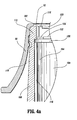
FIG. 4A is a partial cross-sectional view of the probe cover mounted on the distal end of the tympanic thermometer shown inFIG. 2 ; -
FIG. 5 is an enlarged perspective cutaway view of the distal end of the tympanic thermometer shown inFIG. 2 ; -
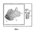
FIG. 6 is a temperature gradient plot for one embodiment of the tympanic thermometer, in accordance with the present disclosure measured at 1.072 seconds after heat has been applied; -
FIG. 7 is a temperature gradient plot for the embodiment of the tympanic thermometer shown inFIG. 6 measured at 3.945 seconds after heat has been applied; -
FIG. 8 is a temperature gradient plot for the embodiment of the tympanic thermometer shown inFIG. 6 measured at 7.229 seconds after heat has been applied; -
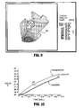
FIG. 9 is a temperature gradient plot for the embodiment of the tympanic thermometer shown inFIG. 6 measured at 10 seconds after heat has been applied; -
FIG. 10 is a time versus temp graph of locations of the sensor temperatures for the embodiment of the tympanic thermometer for the time periods shown inFIG. 6-9 ; -
FIG. 11 is a temperature gradient plot for heat flux for the embodiment of the tympanic thermometer shown inFIG. 6 measured at 1.072 seconds after heat has been applied; and -
FIG. 12 is a temperature gradient plot for heat flux for the embodiment of the tympanic thermometer shown inFIG. 6 measured at 10 seconds after heat has been applied. - The exemplary embodiments of the tympanic thermometer and methods of use disclosed are discussed in terms of medical thermometers for measuring body temperature, and more particularly, in terms of a tympanic thermometer that includes a sensor having a nozzle disposed therewith that improves accuracy of temperature measurement. It is envisioned that the present disclosure finds application for the prevention, diagnosis and treatment of diseases, body ailments, etc. of a subject. It is further envisioned that the principles relating to the tympanic thermometer disclosed include proper removal of a used probe cover via the ejection apparatus and indication to a practitioner whether a new, unused probe is mounted to the tympanic thermometer.
- In the discussion that follows, the term "proximal" will refer to the portion of a structure that is closer to a practitioner, while the term "distal" will refer to the portion that is further from the practitioner. As used herein, the term "subject" refers to a human patient or other animal having its body temperature measured. According to the present disclosure, the term "practitioner" refers to a doctor, nurse, parent or other care provider utilizing a tympanic thermometer to measure a subject's body temperature, and may include support personnel.
- Reference will now be made in detail to the exemplary embodiments of the present disclosure, which are illustrated in the accompanying figures. Turning now to the figures wherein like components are designated by like reference numerals throughout the several views and initially to
FIGS. 1, 2 and the attached disclosure, plots, graphs and figures, there is illustrated atympanic thermometer 20, in accordance with the principles of the present disclosure. -
Tympanic thermometer 20 includes a cylindricalheat sensing probe 22.Heat sensing probe 22 extends from adistal end 24 oftympanic thermometer 20 and defines a longitudinal axis x.Heat sensing probe 22 may have various geometric cross-sectional configurations, such as, for example, rectangular, elliptical, etc. Aprobe cover 32 is mounted todistal end 24. Probecover 32 may be shaped, for example, frustoconically, or shaped in a tapered manner as to allow for easier insertion into the ear of the subject and attachment and detachment from theheat sensing probe 22.Heat sensing probe 22 is configured to detect infrared energy emitted by the tympanic membrane of the subject. - It is contemplated that
tympanic thermometer 20 includes the necessary electronics and/or processing components to perform temperature measurement via the tympanic membrane, as is known to one skilled in the art. It is further envisioned thattympanic thermometer 20 may include a waveguide to facilitate sensing of the tympanic membrane heat energy.Tympanic thermometer 20 is releasably mounted in aholder 40 for storage in contemplation for use.Tympanic thermometer 20 andholder 40 may be fabricated from semi-rigid, rigid plastic and/or metal materials suitable for temperature measurement and related use. It is envisioned thatholder 40 may include the electronics necessary to facilitate powering oftympanic thermometer 20, including, for example, battery charging capability, etc. - Referring to
FIG. 3 , probe cover 32 has adistal end 54 that is substantially enclosed by afilm 56.Film 56 is substantially transparent to infrared radiation and configured to facilitate sensing of infrared emissions byheat sensing probe 22.Film 56 is advantageously impervious to ear wax, moisture and bacteria to prevent disease propagation. - The component portions of the probe cover, which is disposable, are fabricated from materials suitable for measuring body temperature via the tympanic membrane with a tympanic thermometer measuring apparatus. These materials may include, for example, plastic materials, such as, for example, polypropylene, polyethylene, etc., depending on the particular temperature measurement application and/or preference of a practitioner. The probe cover has a window portion or film that can be fabricated from a material substantially transparent to infrared radiation and impervious to moisture, ear wax, bacteria, etc. The film has a thickness in the range of 12.7 to 25.4 µm, although other ranges are contemplated. The film may be semi-rigid or flexible, and can be monolithically formed with the remaining portion of the probe cover or integrally connected thereto via, for example, thermal welding, etc. One skilled in the art, however, will realize that other materials and fabrication methods suitable for assembly and manufacture, in accordance with the present disclosure, also would be appropriate.
- Referring to
FIGS. 4 ,4A and5 ,heat sensing probe 22 includes anozzle 100, a can 102 attached to temperature sensing electronics, asensor housing 104 and abase 106.Nozzle 100 is fabricated from metal or other material which aides in the rapid exchange or transfer of heat.Sensor 104 is housing fabricated from a material which provides for less thermo transmission (i.e., more insulation) thannozzle 100, for example, plastic or other similar matter.Figure 4A discloses a partial cross section of theprobe cover 32 as mounted ontonozzle 100 and anair gap 118 disposed therebetween. As shown,nozzle 100,sensor housing 104 and can 102 are fitted in a secure relationship. Such secure relationship may be established by way of adhesive, friction, press fitting and the like. Anair gap 118 is disposed between thenozzle 100 andsensor housing 104. Can 102 further includessensor base 126,infrared sensor 122, infrared filter orwindow 120 andthermistor 124. - The component parts of
heat sensing probe 22 are assembled andnozzle 100 is mounted thereon to direct heat flux through a distally positioned sensor window atdistal end 108 ofheat sensing probe 22.Nozzle 100 includes abase 110 and anelongated nose portion 112 that facilitate transfer of the heat flux todistal end 108. - In operation, heat from, for example, the ear of the subject, is transferred from probe cover 32 to
nozzle 100. It is contemplated herein thatnozzle 100 may be both in physical contact with thelip 114 or in a close proximate relationship withlip 114 ofcan 102. Such contact enables heat transfer fromnozzle 100 to lip 1,14 ofcan 102. As shown inFIGS. 6-9 and11-12 , heat transfer to can 102 fromlip 114 can occur at any local or single point of contact (FIGS. 6-9 and11-12 disclose such a point of contact along an upper portion of lip 114) or along a plurality of contact points, for example, the entire portion oflip 114. - It is contemplated herein, that can 102 may have a plurality of lips, ribs or other similar structures, for example, detents, nubs, etc., which aid in the heat transfer from
nozzle 100 tocan 102 and ultimately to can tip 116.Lip members 114 may also be formed in a variety of geometric configurations, e.g., helical, dashed, etc. For example, in order to reduce the temperature gradient from thelip 114 to tip 116, (as well as the reduction of the temperature gradient from internal thermistor 124 (FIG. 4A ) and top of can 102), can 102 may have a plurality of lip members made from a metal alloy or other material. Such lip members may be made from separate materials, may be partially in contact with the body ofcan 102, or otherwise be adapted to reduce the temperature gradient fromlip area 114 to can tip 116. - It is also contemplated herein, that can 102 by way of or in addition to the
lips 114 can be pre-heated electrically or by other means to certain preset temperatures.Lip members 114 assist in heat transfer fromnozzle 100, such that the heat gradient fromlip 114 to can tip 116 is reduced. This reduction in the gradient across the sensor tip ofcan 102 provides for faster, more accurate results. - As noted above, and as opposed to other prior art temperature sensing tips, which are designed to insulate sensing tips, the tympanic thermometer of the present disclosure heats the sensor tip (can 102) by way of heat transfer from lip 114 (which receives heat from nozzle 100) in order to reduce the temperature gradient across
tip 116. - As discussed and shown in the
FIGS. 4 ,4A and5 above, sensor can 102 is distally situated along thesensor housing 104 andnozzle 100. Such relationship provides for the sensor to be included within or substantially close to the ear of a subject during a temperature reading. The prior art disclose sensor to ear relationships of this kind; however, these prior art relationships include unique differential heating issues of the sensor. As discussed below and shown inFIGS. 6-12 , the differential heating problems of the prior art have been overcome. - By way of a non-limiting example and referring to
FIGS. 6-12 , one embodiment oftympanic thermometer 20 includesheat sensing probe 22 at an initial temperature of 20°C when a 40°C temperature load is applied to the outside surface ofprobe cover 32. This is similar to takingheat sensing probe 22 from room temperature and disposing it within the ear of a human subject with a fever. As shown, radiation effects are applied to the top face ofsensor housing 104 andnozzle 100. A transient analysis was run for ten (10) seconds for an aluminum nozzle design with a sensor contact. -
FIGS. 6-12 show temperature plots from a simulated temperature reading of the human ear. The data of such were confirmed from actual experimental tests performed on the ear of a subject.FIG. 6 shows a temperature plot of the temperature distribution across the sensor section ofcan 102 after 1.072 seconds. Areas of focus include the surface where the absorber chip and thermistor 124 (FIG. 4A ) are located, the inside top of the sensor can and the inside side of the sensor can.FIG. 7 shows a temperature plot of the temperature distribution across the sensor section after 3.945 seconds.FIG. 8 shows a temperature plot of the temperature distribution across the sensor section after 7.229 seconds.FIG. 9 shows a temperature plot of the temperature distribution across the sensor section after 10 seconds.FIG. 10 shows a plotted graph of the temperature distribution for the 10 second time transient. As shown from the results of a nodal analysis performed at the top, side internal thermistor 124 (FIG. 4A ) ofcan 102, (ΔT) is substantially constant across the 10 second time transient (that is, (ΔT) essentially tracks the thermistor 124 (FIG. 4A )). As such, temperature accuracy errors do not increase with time as in conventional prior art thermometers. Temperature readings can occur at substantially any time along the plotted graph ofFIG. 10 .FIG. 11 shows a temperature plot of the temperature gradient plot for heat flux after 1.072 seconds.FIG. 12 shows a temperature plot of the temperature gradient plot for heat flux after 10 seconds. - It will be understood that various modifications may be made to the embodiments disclosed herein. Therefore, the above description should not be construed as limiting, but merely as exemplification of the various embodiments. Those skilled in the art will envision other modifications within the scope of the claims appended hereto.
Claims (15)
- A tympanic thermometer (20) comprising:a thermometer body;a heat sensing probe (22) extending from said thermometer body; said heat sensing probe including an elongated thermally conductive nozzle (100) having an inner surface defining a cavity;an elongated sensor housing (104) disposed within said cavity and having an air gap (118) separating said sensor housing from said inner surface; anda sensor can (102) mounted on and in direct contact with a distal end of said sensor housing (104), characterised in that said sensor housing (104) is made of a thermally insulating material and in that said sensor can is either contacting said inner surface of said thermally conductive nozzle (100) or is in a close proximal relationship therewith.
- The tympanic thermometer according to claim 1 wherein said heat sensing probe further comprises a base (106) engaging said sensor housing and said nozzle and providing coaxial alignment therebetween.
- The tympanic thermometer according to claim 2 wherein said base comprises means for attaching said sensing probe to said thermometer body.
- The tympanic thermometer according to claim 1 wherein said sensor can (102) includes at least one protrusion (114) extending radially outward, said at least one protrusion providing at least one contact point between said inner surface of said nozzle and said can to facilitate heat flow therebetween.
- The tympanic thermometer according to claim 4 wherein said at least one protrusion (114) comprises a lip.
- The tympanic thermometer according to claim 5 wherein said lip comprises a plurality of lip members.
- The tympanic thermometer according to claim 6 wherein said plurality of lip members extend from said sensor can to form a helical protrusion contacting said inside surface of said nozzle.
- The tympanic thermometer according to claim 4 wherein said at least one protrusion (114) is made from a metal alloy.
- The tympanic thermometer according to claim 4 wherein at least one of said protrusions is made from a material different from at least one other of said protrusions.
- The tympanic thermometer according to claim 8 wherein said at least one protrusion (114) is made from a material selected to provide an optimized heat flow rate.
- The tympanic thermometer according to claim 4 wherein at least one of said protrusions (114) is electrically preheated to reduce the temperature gradient in said heat sensing probe.
- The tympanic thermometer according to claim 1 wherein said sensor can incorporates:at least one infrared transmissive window (120) in a said can;a sensor base having a distal surface; andan infrared sensor (122) disposed on said distal surface and receiving infrared radiation through said infrared transmissive window.
- The tympanic thermometer according to claim 1 further characterised by a disposable probe cover (32) disposed over said heat sensing probe, said probe cover including an infrared transmissive film (56) substantially enclosing a distal end of said probe cover and aligned with a distal opening of said nozzle.
- The tympanic thermometer according to claim 1 wherein said sensor can (102) comprises:a can surface and a thermistor (124) incorporated in said sensor can; andwherein a temperature differential between said can surface and said thermistor remains substantially constant while ambient temperature changes over time.
- The tympanic thermometer according to claim 14 wherein said constant temperature differential is provided by optimizing a heat conduction path between an ambient environment and said can surface.
Priority Applications (1)
| Application Number | Priority Date | Filing Date | Title |
|---|---|---|---|
| EP07012177A EP1840543B1 (en) | 2002-12-12 | 2003-04-15 | Method of assembling a tympanic thermometer |
Applications Claiming Priority (3)
| Application Number | Priority Date | Filing Date | Title |
|---|---|---|---|
| US43290402P | 2002-12-12 | 2002-12-12 | |
| US432904P | 2002-12-12 | ||
| PCT/US2003/011606 WO2004055488A1 (en) | 2002-12-12 | 2003-04-15 | Thermal tympanic thermometer tip |
Related Child Applications (1)
| Application Number | Title | Priority Date | Filing Date |
|---|---|---|---|
| EP07012177A Division EP1840543B1 (en) | 2002-12-12 | 2003-04-15 | Method of assembling a tympanic thermometer |
Publications (2)
| Publication Number | Publication Date |
|---|---|
| EP1570246A1 EP1570246A1 (en) | 2005-09-07 |
| EP1570246B1 true EP1570246B1 (en) | 2009-01-14 |
Family
ID=32595095
Family Applications (2)
| Application Number | Title | Priority Date | Filing Date |
|---|---|---|---|
| EP07012177A Expired - Lifetime EP1840543B1 (en) | 2002-12-12 | 2003-04-15 | Method of assembling a tympanic thermometer |
| EP03721680A Expired - Lifetime EP1570246B1 (en) | 2002-12-12 | 2003-04-15 | Thermal tympanic thermometer tip |
Family Applications Before (1)
| Application Number | Title | Priority Date | Filing Date |
|---|---|---|---|
| EP07012177A Expired - Lifetime EP1840543B1 (en) | 2002-12-12 | 2003-04-15 | Method of assembling a tympanic thermometer |
Country Status (18)
| Country | Link |
|---|---|
| US (3) | US7108419B2 (en) |
| EP (2) | EP1840543B1 (en) |
| JP (1) | JP4409441B2 (en) |
| KR (1) | KR20050085499A (en) |
| CN (1) | CN100488445C (en) |
| AT (2) | ATE421082T1 (en) |
| AU (1) | AU2003224980B2 (en) |
| BR (1) | BR0317262A (en) |
| CA (1) | CA2509033C (en) |
| DE (1) | DE60325891D1 (en) |
| DK (1) | DK1570246T3 (en) |
| ES (2) | ES2319275T3 (en) |
| HK (1) | HK1074076A1 (en) |
| IL (1) | IL181374A (en) |
| MX (1) | MXPA05006157A (en) |
| NO (1) | NO20053382D0 (en) |
| PT (1) | PT1570246E (en) |
| WO (1) | WO2004055488A1 (en) |
Families Citing this family (45)
| Publication number | Priority date | Publication date | Assignee | Title |
|---|---|---|---|---|
| JP3675230B2 (en) * | 1999-06-11 | 2005-07-27 | オムロンヘルスケア株式会社 | Ear thermometer |
| US7434991B2 (en) * | 2002-12-12 | 2008-10-14 | Covidien Ag | Thermal tympanic thermometer |
| CA2509033C (en) | 2002-12-12 | 2011-10-11 | Sherwood Services Ag | Thermal tympanic thermometer tip |
| US7354194B2 (en) | 2003-01-06 | 2008-04-08 | Covidien Ag | Tympanic thermometer probe cover with film support mechanism |
| DE60315895T2 (en) * | 2003-01-06 | 2008-05-29 | Covidien Ag | PROBE COVER FOR DRUM FILL THERMOMETER |
| US20060120432A1 (en) * | 2003-01-06 | 2006-06-08 | Loren Lantz | Tympanic thermometer with ejection mechanism |
| US7478946B2 (en) * | 2003-01-06 | 2009-01-20 | Covidien Ag | Probe cover cassette with improved probe cover support |
| US20050228307A1 (en) * | 2004-04-13 | 2005-10-13 | Steve Gibree | Removable medical device adapter |
| US20060050769A1 (en) * | 2004-09-08 | 2006-03-09 | Yung-Ku Lee | Waterproof infrared ear thermometer |
| US7083330B1 (en) * | 2004-10-19 | 2006-08-01 | Huang Hua Co., Ltd. | Ear thermometer having breakable ear cap |
| TW200615520A (en) * | 2004-11-09 | 2006-05-16 | Norm Pacific Automat Corp | Infrared thermometer |
| US7857507B2 (en) * | 2004-11-16 | 2010-12-28 | Welch Allyn, Inc. | Temperature patch and method of using the same |
| US7815367B2 (en) * | 2004-11-16 | 2010-10-19 | Welch Allyn, Inc. | Multi-site infrared thermometer |
| US7275867B2 (en) * | 2005-12-01 | 2007-10-02 | Oriental System Technology Inc. | Probe assembly of infrared thermometer |
| US20070248141A1 (en) | 2006-04-21 | 2007-10-25 | Sherwood Services Ag | Infrared thermometer and probe cover thereof |
| TWI280356B (en) * | 2006-05-09 | 2007-05-01 | Radiant Innovation Inc | Ear cap of ear thermometer |
| US7507019B2 (en) | 2006-05-19 | 2009-03-24 | Covidien Ag | Thermometer calibration |
| US7549792B2 (en) | 2006-10-06 | 2009-06-23 | Covidien Ag | Electronic thermometer with selectable modes |
| US7824102B2 (en) * | 2006-12-09 | 2010-11-02 | Shenzhen Mindray Bio-Medical Electronics, Inc. | Thermometer quick linkage apparatus and method |
| US8652040B2 (en) | 2006-12-19 | 2014-02-18 | Valencell, Inc. | Telemetric apparatus for health and environmental monitoring |
| US8308353B2 (en) * | 2007-03-26 | 2012-11-13 | Terumo Kabushiki Kaisha | Ear thermometer and method of manufacturing ear thermometer |
| TW200841859A (en) * | 2007-04-27 | 2008-11-01 | Actherm Inc | Infrared thermometer |
| EP2161556B1 (en) * | 2007-06-12 | 2013-03-27 | Bio Echo Net Inc | Ear thermometer and measurement device body used for the same |
| US8100886B2 (en) * | 2007-08-15 | 2012-01-24 | Visiomed Group Sa | Aspirator assembly |
| US20090076441A1 (en) * | 2007-08-15 | 2009-03-19 | Eric Sebban | Aspirator assembly |
| US20130096437A1 (en) * | 2007-08-21 | 2013-04-18 | Radiant Innovation Inc. | Method for detecting temple hot spot temperature of a live body |
| US20090074027A1 (en) * | 2007-09-18 | 2009-03-19 | Vatell Corporation | Heat flux sensor incorporating light conveyance |
| TWI340822B (en) * | 2007-11-15 | 2011-04-21 | Actherm Inc | Probe cover for an ear thermometer, manufacturing method thereof |
| US8303177B2 (en) * | 2008-03-31 | 2012-11-06 | Hsueh-Yu Lu | Pre-heat type clinical thermometer |
| US8192075B2 (en) * | 2008-08-19 | 2012-06-05 | Ge Inspection Technologies, Lp | Method for performing ultrasonic testing |
| US8876373B2 (en) | 2009-04-09 | 2014-11-04 | Welch Allyn, Inc. | IR thermometry probe cover |
| US8231271B2 (en) * | 2009-04-09 | 2012-07-31 | Welch Allyn, Inc. | IR thermometry probe cover |
| USD787683S1 (en) | 2009-04-09 | 2017-05-23 | Welch Allyn, Inc. | Cover for a probe |
| US8186876B2 (en) * | 2009-04-20 | 2012-05-29 | Welch Allyn, Inc. | Calibrated assembly for IR thermometer apparatus |
| EP2486379B1 (en) * | 2009-10-05 | 2018-08-15 | KAZ Europe SA | Attachment mechanism for ear thermometers |
| US8657758B2 (en) | 2010-12-02 | 2014-02-25 | Welch Allyn, Inc. | Devices and methods for temperature determination |
| JP2013013540A (en) * | 2011-07-04 | 2013-01-24 | Sony Corp | Auricle-installed apparatus |
| JP2013202260A (en) * | 2012-03-29 | 2013-10-07 | Sony Corp | Information processing apparatus, method for processing information, and computer program |
| DE102012223691A1 (en) * | 2012-12-19 | 2014-06-26 | Heine Optotechnik Gmbh & Co Kg | Otoscope with disposable ear funnel |
| CN103284698A (en) * | 2013-05-13 | 2013-09-11 | 曾建新 | Miniature rapid body temperature sensing device |
| US20150317909A1 (en) * | 2014-04-30 | 2015-11-05 | Peter Florkoski | Apparatus and method of simulating a thermometer |
| JP7239150B2 (en) * | 2018-12-14 | 2023-03-14 | 株式会社バイオエコーネット | ear thermometer |
| CN210089862U (en) * | 2019-07-11 | 2020-02-18 | 深圳市福瑞诺科技有限公司 | Dual-purpose infrared ear thermometer easy to clean |
| JP7031646B2 (en) * | 2019-09-24 | 2022-03-08 | カシオ計算機株式会社 | Detection device and manufacturing method of detection device |
| WO2021234986A1 (en) * | 2020-05-19 | 2021-11-25 | 拓則 島崎 | Physical condition change detection device and physical condition change management system |
Family Cites Families (155)
| Publication number | Priority date | Publication date | Assignee | Title |
|---|---|---|---|---|
| US3491596A (en) * | 1967-10-02 | 1970-01-27 | Vito Charles P De | Temperature sensing device |
| US3738173A (en) | 1971-11-22 | 1973-06-12 | Ivac Corp | Temperature sensing probe and disposable probe cover |
| US4005605A (en) | 1974-07-22 | 1977-02-01 | Mikron Instrument Company, Inc. | Remote reading infrared thermometer |
| US4346427A (en) | 1979-06-29 | 1982-08-24 | Robert Rothenhaus | Control device responsive to infrared radiation |
| DE2953811A1 (en) | 1979-09-12 | 1982-02-11 | M Jacobs | HAND HERO DIGITAL TEMPERATURE MEASURING INSTRUMENT |
| US4343182A (en) | 1980-07-14 | 1982-08-10 | Exergen Corporation | Radiation heat loss detector |
| US4456390A (en) | 1981-10-26 | 1984-06-26 | Wahl Instruments, Inc. | Noncontact temperature measuring device |
| US4527896A (en) | 1982-03-04 | 1985-07-09 | Mikron Instrument Company, Inc. | Infrared transducer-transmitter for non-contact temperature measurement |
| US4566808A (en) | 1983-02-16 | 1986-01-28 | Exergen Corporation | Scanning radiation detector |
| JPS6054070A (en) | 1983-09-02 | 1985-03-28 | Nec Corp | Arithmetic unit |
| US4626686A (en) | 1984-04-09 | 1986-12-02 | Exergen Corporation | Variable field of view heat scanner |
| US5179936A (en) | 1984-10-23 | 1993-01-19 | Intelligent Medical Systems, Inc. | Disposable speculum with membrane bonding ring |
| US4602642A (en) | 1984-10-23 | 1986-07-29 | Intelligent Medical Systems, Inc. | Method and apparatus for measuring internal body temperature utilizing infrared emissions |
| US4790324A (en) | 1984-10-23 | 1988-12-13 | Intelligent Medical Systems, Inc. | Method and apparatus for measuring internal body temperature utilizing infrared emissions |
| US4662360A (en) | 1984-10-23 | 1987-05-05 | Intelligent Medical Systems, Inc. | Disposable speculum |
| US4588306A (en) | 1985-03-22 | 1986-05-13 | Chesebrough-Pond's Inc. | Electronic thermometer probe assembly |
| DE3650770T2 (en) | 1985-04-17 | 2003-02-27 | Thermoscan Inc | Electronic infrared thermometer and method for temperature measurement |
| US4682898A (en) | 1985-06-06 | 1987-07-28 | Honeywell Inc. | Method and apparatus for measuring a varying parameter |
| US4636091A (en) | 1985-06-27 | 1987-01-13 | Exergen Corporation | Radiation detector having temperature readout |
| US4722612A (en) | 1985-09-04 | 1988-02-02 | Wahl Instruments, Inc. | Infrared thermometers for minimizing errors associated with ambient temperature transients |
| US4784149A (en) | 1986-01-13 | 1988-11-15 | Optical Sensors, Inc. | Infrared thermometer with automatic calibration |
| US4874253A (en) | 1987-03-27 | 1989-10-17 | Exergen Corporation | Radiation detector with temperature display |
| US4854730A (en) | 1987-08-13 | 1989-08-08 | Jacob Fraden | Radiation thermometer and method for measuring temperature |
| WO1989006348A1 (en) * | 1987-12-25 | 1989-07-13 | Nippon Steel Corporation | Optical thermometer |
| US4896039A (en) | 1987-12-31 | 1990-01-23 | Jacob Fraden | Active infrared motion detector and method for detecting movement |
| US4831258A (en) | 1988-03-04 | 1989-05-16 | Exergen Corporation | Dual sensor radiation detector |
| JP2826337B2 (en) | 1988-04-12 | 1998-11-18 | シチズン時計株式会社 | Radiation thermometer |
| US4867574A (en) | 1988-05-19 | 1989-09-19 | Jenkofsky John J | Ultra high speed infrared temperature measuring device |
| US4895164A (en) | 1988-09-15 | 1990-01-23 | Telatemp Corp. | Infrared clinical thermometer |
| US5018872A (en) * | 1988-11-01 | 1991-05-28 | Diatek, Inc. | Probe assembly for infrared thermometer |
| US4911559A (en) | 1988-11-01 | 1990-03-27 | Diatek, Inc. | Disposable probe cover assembly for medical thermometer |
| US4993419A (en) | 1988-12-06 | 1991-02-19 | Exergen Corporation | Radiation detector suitable for tympanic temperature measurement |
| US5445158A (en) | 1988-12-06 | 1995-08-29 | Exergen Corporation | Radiation detector probe |
| US5012813A (en) | 1988-12-06 | 1991-05-07 | Exergen Corporation | Radiation detector having improved accuracy |
| US5199436A (en) | 1988-12-06 | 1993-04-06 | Exergen Corporation | Radiation detector having improved accuracy |
| US5325863A (en) | 1988-12-06 | 1994-07-05 | Exergen Corporation | Radiation detector with high thermal stability |
| US5271407A (en) | 1988-12-06 | 1993-12-21 | Exergen Corporation | Radiation detector suitable for tympanic temperature measurement |
| US5381796A (en) | 1992-05-22 | 1995-01-17 | Exergen Corporation | Ear thermometer radiation detector |
| US6219573B1 (en) * | 1989-04-14 | 2001-04-17 | Exergen Corporation | Radiation detector probe |
| US4900162A (en) | 1989-03-20 | 1990-02-13 | Ivac Corporation | Infrared thermometry system and method |
| US5019804A (en) | 1989-04-10 | 1991-05-28 | Jacob Fraden | Apparatus and method for detecting movement of an object |
| US5017019A (en) | 1989-04-14 | 1991-05-21 | Exergen Corporation | Radiation detector for differential biological temperature readings |
| US5163418A (en) | 1989-09-19 | 1992-11-17 | Thermoscan Inc. | Speculum cover |
| US5054936A (en) | 1989-11-16 | 1991-10-08 | Jacob Fraden | Sensor for active thermal detection |
| US4993424A (en) | 1989-12-04 | 1991-02-19 | Diatek, Incorporated | Infrared medical thermometer |
| US5066142A (en) | 1990-03-08 | 1991-11-19 | Ivac Corporation | Protective apparatus for a biomedical probe |
| DE69132890T2 (en) * | 1990-03-08 | 2002-08-29 | Alaris Medical Syst Inc | Thermally insulated probe |
| US5150969A (en) | 1990-03-12 | 1992-09-29 | Ivac Corporation | System and method for temperature determination and calibration in a biomedical probe |
| US5081359A (en) | 1990-05-23 | 1992-01-14 | Exergen Corporation | Differential thermal sensor |
| DE69114502T3 (en) | 1990-08-01 | 2002-10-02 | Exergen Corp | RADIATION DETECTOR WITH REMOTE TEMPERATURE REFERENCE LOCATION |
| US5229612B1 (en) | 1990-08-01 | 1998-04-14 | Exergen Corp | Radiation detector with remote temperature reference |
| US5159936A (en) * | 1990-08-17 | 1992-11-03 | Mark Yelderman | Noncontact infrared tympanic thermometer |
| US5088834A (en) | 1990-08-24 | 1992-02-18 | Thermoscan Inc. | Unitary probe cover |
| US5119436A (en) | 1990-09-24 | 1992-06-02 | Kulicke And Soffa Industries, Inc | Method of centering bond positions |
| EP0562039B2 (en) | 1990-12-12 | 2001-04-18 | Sherwood Medical Company | Infrared thermometer utilizing calibration mapping |
| JP3179788B2 (en) | 1991-01-17 | 2001-06-25 | 三菱電機株式会社 | Semiconductor storage device |
| US5469855A (en) | 1991-03-08 | 1995-11-28 | Exergen Corporation | Continuous temperature monitor |
| US5127742A (en) | 1991-04-19 | 1992-07-07 | Thermoscan Inc. | Apparatus and method for temperature measurement by radiation |
| US5178464A (en) | 1991-04-19 | 1993-01-12 | Thermoscan Inc. | Balance infrared thermometer and method for measuring temperature |
| US5183337A (en) | 1991-07-08 | 1993-02-02 | Exergen Corporation | Thermometer calibration |
| US5333784A (en) | 1993-03-02 | 1994-08-02 | Exergen Corporation | Radiation detector with thermocouple calibration and remote temperature reference |
| US5368038A (en) | 1993-03-08 | 1994-11-29 | Thermoscan Inc. | Optical system for an infrared thermometer |
| US5411032A (en) | 1993-06-18 | 1995-05-02 | Infra-Temp Inc. | Electronic thermometer probe cover |
| DE4331574C2 (en) | 1993-09-16 | 1997-07-10 | Heimann Optoelectronics Gmbh | Infrared sensor module |
| US20030185273A1 (en) | 1993-09-17 | 2003-10-02 | Hollander Milton Bernard | Laser directed temperature measurement |
| US5645349A (en) | 1994-01-10 | 1997-07-08 | Thermoscan Inc. | Noncontact active temperature sensor |
| US5646349A (en) * | 1994-02-18 | 1997-07-08 | Plan B Enterprises, Inc. | Floating mass accelerometer |
| WO1995022928A1 (en) | 1994-02-28 | 1995-08-31 | Economation, Inc. | Infrared tympanic thermometer |
| IT1272219B (en) * | 1994-04-27 | 1997-06-16 | Siv Soc Italiana Vetro | APPARATUS FOR THE CONTROL OF AN ELECTROCHROMIC WINDOW |
| US5626139A (en) | 1994-09-23 | 1997-05-06 | Artech Industries, Inc. | Tympanic thermometer |
| JP2000500371A (en) | 1995-11-18 | 2000-01-18 | ブラウン アクチェンゲゼルシャフト | Infrared thermometer and method for evaluating a signal provided by an infrared sensor of an infrared thermometer |
| DE19543096C2 (en) | 1995-11-18 | 1998-07-23 | Braun Ag | Infrared radiation thermometer |
| DE69630395T2 (en) | 1995-12-28 | 2004-08-05 | Omron Healthcare Co., Ltd. | INFRARED THERMOMETER |
| DE19604201A1 (en) * | 1996-02-06 | 1997-08-07 | Braun Ag | protective cap |
| US5820264A (en) | 1996-03-25 | 1998-10-13 | Oriental System Technology, Inc. | Tympanic thermometer arrangement |
| US5645350A (en) * | 1996-04-12 | 1997-07-08 | Jang; Chen-Chang | Hygienic protecting device for an electronic thermometer |
| US6179785B1 (en) * | 1996-10-17 | 2001-01-30 | Sherwood Services, Ag | Ambient sensing feature for thermometer recalibration system |
| US5874736A (en) * | 1996-10-25 | 1999-02-23 | Exergen Corporation | Axillary infrared thermometer and method of use |
| FR2773213B1 (en) | 1996-12-11 | 2001-08-24 | Omega Engineering | METHOD AND DEVICE FOR INFRARED MEASUREMENT OF THE SURFACE TEMPERATURE |
| WO1998055841A2 (en) | 1997-06-03 | 1998-12-10 | Trutek Inc. | Tympanic thermometer with modular sensing probe |
| CN100394885C (en) * | 1997-07-16 | 2008-06-18 | 泰尔茂株式会社 | Ear type clinical thermometer |
| JPH1147098A (en) * | 1997-08-08 | 1999-02-23 | Omron Corp | Radial thermometer |
| JP4018782B2 (en) * | 1997-09-10 | 2007-12-05 | シチズンホールディングス株式会社 | Radiation thermometer |
| DE19757447A1 (en) * | 1997-12-23 | 1999-07-01 | Braun Gmbh | Temperature calculation method for radiation thermometers |
| US6129673A (en) * | 1998-06-08 | 2000-10-10 | Advanced Monitors, Corp. | Infrared thermometer |
| US6224256B1 (en) | 1998-06-18 | 2001-05-01 | Harry Bala | Cover for medical probe |
| US6292685B1 (en) * | 1998-09-11 | 2001-09-18 | Exergen Corporation | Temporal artery temperature detector |
| IL126224A0 (en) * | 1998-09-15 | 1999-05-09 | Gerlitz Jonathan | Ear thermometer and detector therefor |
| WO2000016047A1 (en) | 1998-09-16 | 2000-03-23 | Braun Gmbh | Method for determining temperature, radiation thermometer with several infrared sensor elements |
| JP3514138B2 (en) | 1998-09-29 | 2004-03-31 | テルモ株式会社 | Probe cover removal mechanism and ear thermometer |
| DE69934508T2 (en) | 1998-10-20 | 2007-09-27 | Omron Healthcare Co., Ltd. | INFRARED THERMOMETER |
| DE29819056U1 (en) | 1998-10-26 | 1999-02-25 | Chen Chao Wang | Infrared thermometer |
| US6572264B1 (en) * | 1998-12-15 | 2003-06-03 | Citizen Watch Co., Ltd. | Radiation clinical thermometer |
| DE29902276U1 (en) | 1999-02-09 | 1999-04-15 | Chen Chao Wang | Infrared sensor for a thermometer |
| US6139182A (en) | 1999-03-01 | 2000-10-31 | Thermoscan, Inc | Enhanced protective cover for use in an IR thermometer |
| DE19913672A1 (en) | 1999-03-25 | 2000-11-02 | Braun Gmbh | Infrared thermometer with a heatable measuring tip and protective cap |
| DE29907098U1 (en) | 1999-04-21 | 1999-07-22 | Chen | Test head for an infrared thermometer |
| US6901089B1 (en) | 1999-07-02 | 2005-05-31 | Milton Bernard Hollander | Laser instrument |
| DE19942214A1 (en) * | 1999-09-03 | 2001-03-08 | Braun Gmbh | Heated infrared sensor and infrared thermometer with such a sensor |
| USD464555S1 (en) | 1999-10-28 | 2002-10-22 | The Eastern Company | Portions of a clamp bracket assembly for use with push button latch and lock operating assemblies |
| US6983753B1 (en) | 1999-11-17 | 2006-01-10 | Smithkline Beecham Corporation | Infrared thermography |
| US6319206B1 (en) | 1999-11-24 | 2001-11-20 | Exergen Corporation | Temporal thermometer disposable cap |
| US6227256B1 (en) * | 1999-12-13 | 2001-05-08 | Albany International Corp. | Multi-layer papermaking fabric having long weft floats on its support and machine surfaces |
| GB0005926D0 (en) | 2000-03-10 | 2000-05-03 | Univ Glasgow | Microwave radiometry |
| US6390671B1 (en) | 2000-04-28 | 2002-05-21 | K-Jump Health Co., Ltd. | Probe cover with film insert |
| IT1317648B1 (en) | 2000-05-19 | 2003-07-15 | Tecnica S R L | PERFECTED INFRARED THERMOMETER |
| DE10025157A1 (en) * | 2000-05-23 | 2001-11-29 | Braun Gmbh | Infrared radiation thermometer with changeable measuring tip |
| US7036978B2 (en) | 2000-06-13 | 2006-05-02 | Omron Corporation | Pyrometer |
| TW437956U (en) | 2000-09-15 | 2001-05-28 | Peng Shau Yu | Ear thermometer with rotating-type probing head |
| US7014358B2 (en) | 2001-02-19 | 2006-03-21 | Braun Gmbh | Radiation thermometer comprising a heated measuring tip |
| EP1239271A1 (en) | 2001-03-07 | 2002-09-11 | Microlife Intellectual Property GmbH | An infrared medical thermometer |
| EP1249691A1 (en) | 2001-04-11 | 2002-10-16 | Omron Corporation | Electronic clinical thermometer |
| JP2002345761A (en) | 2001-05-22 | 2002-12-03 | Omron Corp | Infrared thermometer probe |
| KR100363284B1 (en) * | 2001-05-22 | 2002-12-11 | 주식회사 메타텍 | An Infrared Thermometer |
| JP3945189B2 (en) * | 2001-06-01 | 2007-07-18 | オムロンヘルスケア株式会社 | Infrared thermometer |
| JP3900865B2 (en) | 2001-06-04 | 2007-04-04 | オムロンヘルスケア株式会社 | Infrared thermometer, infrared thermometer temperature state estimation method, information notification method, and measurement operation management method |
| US6637931B2 (en) * | 2001-07-19 | 2003-10-28 | Oriental System Technology Inc. | Probe for use in an infrared thermometer |
| US20030067958A1 (en) | 2001-10-09 | 2003-04-10 | Chen-Chang Jang | Infrared thermometer as measured on forehead artery area |
| US6749334B2 (en) * | 2002-08-09 | 2004-06-15 | Radiant Innovation Inc. | Ear thermometer probe structure |
| US20040047392A1 (en) | 2002-09-06 | 2004-03-11 | Shu-Mei Wu | Apparatus for measuring ear and forehead temperature |
| US6979121B2 (en) | 2002-10-18 | 2005-12-27 | Mesure Technology, Co., Ltd. | Temperature probe and thermometer having the same |
| TW567054B (en) | 2002-11-28 | 2003-12-21 | Actherm Inc | Method for assembling electric clinical thermometer and structure thereof |
| US6981796B2 (en) | 2002-12-04 | 2006-01-03 | Actherm Inc. | Electronic thermometer |
| JP2004191075A (en) | 2002-12-06 | 2004-07-08 | Matsushita Electric Ind Co Ltd | Temperature measuring device, temperature correction method, and image formation device |
| CA2509033C (en) | 2002-12-12 | 2011-10-11 | Sherwood Services Ag | Thermal tympanic thermometer tip |
| US6950028B2 (en) | 2003-04-25 | 2005-09-27 | Stephen Eliot Zweig | Electronic time-temperature indicator |
| US6886979B2 (en) | 2003-05-23 | 2005-05-03 | Carl J Conforti | Temperature measure device |
| US7374336B2 (en) | 2003-06-16 | 2008-05-20 | Jacob Fraden | Contact thermometer for body cavity |
| TWM266444U (en) | 2003-08-29 | 2005-06-01 | Mesure Technology Co Ltd | Foldable sensing head and its clinical thermometer |
| DE10341433A1 (en) | 2003-09-09 | 2005-03-31 | Braun Gmbh | Heatable infrared sensor and infrared thermometer with such an infrared sensor |
| US20050085733A1 (en) | 2003-10-17 | 2005-04-21 | Anthony Wong | Ear thermometer illumination system |
| US20050083991A1 (en) | 2003-10-17 | 2005-04-21 | Anthony Wong | Probe cover storage system for ear thermometer |
| US7021824B2 (en) | 2003-10-20 | 2006-04-04 | Welch Allyn, Inc. | Switch assembly for thermometry apparatus |
| TWM244878U (en) | 2003-10-21 | 2004-10-01 | Innovatech Inc | Electric ear thermometer capable of storing a number of people's data |
| TW593993B (en) | 2003-11-03 | 2004-06-21 | Oriental System Technology Inc | Electrical thermometer |
| EP1530034A1 (en) | 2003-11-05 | 2005-05-11 | Microlife Intellectual Property GmbH | An infrared thermometer and a method for determining a temperature |
| US20050157775A1 (en) | 2003-11-17 | 2005-07-21 | Maverick Industries, Inc. | Temperature probe and use thereof |
| US7611278B2 (en) | 2003-12-02 | 2009-11-03 | White Box, Inc. | Infrared thermometers |
| US20050207470A1 (en) | 2004-01-26 | 2005-09-22 | Bennett Timothy J | Focusing thermometer |
| TWM251738U (en) | 2004-01-30 | 2004-12-01 | Yuan Ho Harmony Co Ltd | Infrared temperature sensor |
| DK1734858T3 (en) | 2004-03-22 | 2014-10-20 | Bodymedia Inc | NON-INVASIVE TEMPERATURE MONITORING DEVICE |
| US20050209516A1 (en) | 2004-03-22 | 2005-09-22 | Jacob Fraden | Vital signs probe |
| US20050226307A1 (en) | 2004-04-07 | 2005-10-13 | Sherin Lussier | Infrared thermometer |
| US20050276308A1 (en) | 2004-06-10 | 2005-12-15 | Pint Charles S | Method and apparatus for measuring temperature and emissivity |
| US20060050769A1 (en) * | 2004-09-08 | 2006-03-09 | Yung-Ku Lee | Waterproof infrared ear thermometer |
| TW200615520A (en) * | 2004-11-09 | 2006-05-16 | Norm Pacific Automat Corp | Infrared thermometer |
| JP2005128033A (en) | 2004-12-27 | 2005-05-19 | Omron Healthcare Co Ltd | Radiation thermometer |
| JP4148219B2 (en) | 2004-12-27 | 2008-09-10 | オムロンヘルスケア株式会社 | Radiation thermometer |
| JP2005128031A (en) | 2004-12-27 | 2005-05-19 | Omron Healthcare Co Ltd | Radiation thermometer |
| JP2005128034A (en) | 2004-12-27 | 2005-05-19 | Omron Healthcare Co Ltd | Radiation thermometer |
| US20060153278A1 (en) * | 2005-01-11 | 2006-07-13 | Kun-Sung Chen | Ear thermometer |
| US20060198424A1 (en) * | 2005-03-02 | 2006-09-07 | Kun-Sung Chen | Probe structure for an ear thermometer |
| US20060215728A1 (en) * | 2005-03-28 | 2006-09-28 | Chen-Chang Jang | Forehead thermometer for hygienic measurement |
| US7275867B2 (en) * | 2005-12-01 | 2007-10-02 | Oriental System Technology Inc. | Probe assembly of infrared thermometer |
| US7988352B2 (en) * | 2006-11-01 | 2011-08-02 | Radiant Innovation Inc. | Probe structure |
-
2003
- 2003-04-15 CA CA2509033A patent/CA2509033C/en not_active Expired - Lifetime
- 2003-04-15 AT AT03721680T patent/ATE421082T1/en not_active IP Right Cessation
- 2003-04-15 CN CNB038256126A patent/CN100488445C/en not_active Expired - Fee Related
- 2003-04-15 MX MXPA05006157A patent/MXPA05006157A/en active IP Right Grant
- 2003-04-15 ES ES03721680T patent/ES2319275T3/en not_active Expired - Lifetime
- 2003-04-15 KR KR1020057010504A patent/KR20050085499A/en not_active Application Discontinuation
- 2003-04-15 PT PT03721680T patent/PT1570246E/en unknown
- 2003-04-15 AU AU2003224980A patent/AU2003224980B2/en not_active Expired
- 2003-04-15 AT AT07012177T patent/ATE523770T1/en not_active IP Right Cessation
- 2003-04-15 EP EP07012177A patent/EP1840543B1/en not_active Expired - Lifetime
- 2003-04-15 BR BR0317262-7A patent/BR0317262A/en not_active Application Discontinuation
- 2003-04-15 US US10/480,428 patent/US7108419B2/en not_active Expired - Lifetime
- 2003-04-15 DK DK03721680T patent/DK1570246T3/en active
- 2003-04-15 EP EP03721680A patent/EP1570246B1/en not_active Expired - Lifetime
- 2003-04-15 DE DE60325891T patent/DE60325891D1/en not_active Expired - Lifetime
- 2003-04-15 WO PCT/US2003/011606 patent/WO2004055488A1/en active IP Right Grant
- 2003-04-15 ES ES07012177T patent/ES2372200T3/en not_active Expired - Lifetime
- 2003-04-15 JP JP2004560260A patent/JP4409441B2/en not_active Expired - Fee Related
-
2005
- 2005-05-06 US US11/123,902 patent/US7140764B2/en not_active Expired - Lifetime
- 2005-07-12 NO NO20053382A patent/NO20053382D0/en not_active Application Discontinuation
- 2005-09-15 HK HK05108067.6A patent/HK1074076A1/en not_active IP Right Cessation
-
2007
- 2007-02-15 IL IL181374A patent/IL181374A/en not_active IP Right Cessation
-
2008
- 2008-08-08 US US12/188,878 patent/US7841767B2/en not_active Expired - Lifetime
Also Published As
| Publication number | Publication date |
|---|---|
| ES2319275T3 (en) | 2009-05-06 |
| IL181374A (en) | 2011-11-30 |
| CA2509033A1 (en) | 2004-07-01 |
| US7108419B2 (en) | 2006-09-19 |
| KR20050085499A (en) | 2005-08-29 |
| JP2006509576A (en) | 2006-03-23 |
| CN1714283A (en) | 2005-12-28 |
| ATE523770T1 (en) | 2011-09-15 |
| EP1570246A1 (en) | 2005-09-07 |
| ATE421082T1 (en) | 2009-01-15 |
| US20080298429A1 (en) | 2008-12-04 |
| CN100488445C (en) | 2009-05-20 |
| JP4409441B2 (en) | 2010-02-03 |
| AU2003224980A1 (en) | 2004-07-09 |
| NO20053382L (en) | 2005-07-12 |
| CA2509033C (en) | 2011-10-11 |
| EP1840543A1 (en) | 2007-10-03 |
| MXPA05006157A (en) | 2005-08-26 |
| ES2372200T3 (en) | 2012-01-17 |
| AU2003224980B2 (en) | 2007-03-15 |
| US20050254549A1 (en) | 2005-11-17 |
| DK1570246T3 (en) | 2009-04-20 |
| US20040240516A1 (en) | 2004-12-02 |
| US7140764B2 (en) | 2006-11-28 |
| DE60325891D1 (en) | 2009-03-05 |
| IL181374A0 (en) | 2007-07-04 |
| HK1074076A1 (en) | 2005-10-28 |
| BR0317262A (en) | 2005-11-08 |
| NO20053382D0 (en) | 2005-07-12 |
| EP1840543B1 (en) | 2011-09-07 |
| PT1570246E (en) | 2009-04-09 |
| US7841767B2 (en) | 2010-11-30 |
| WO2004055488A1 (en) | 2004-07-01 |
Similar Documents
| Publication | Publication Date | Title |
|---|---|---|
| EP1570246B1 (en) | Thermal tympanic thermometer tip | |
| EP1857795B1 (en) | Tympanic thermometer | |
| EP1860413B1 (en) | Tympanic thermometer probe cover | |
| AU2007200873B2 (en) | Thermal tympanic thermometer tip |
Legal Events
| Date | Code | Title | Description |
|---|---|---|---|
| PUAI | Public reference made under article 153(3) epc to a published international application that has entered the european phase |
Free format text: ORIGINAL CODE: 0009012 |
|
| 17P | Request for examination filed |
Effective date: 20050610 |
|
| AK | Designated contracting states |
Kind code of ref document: A1 Designated state(s): AT BE BG CH CY CZ DE DK EE ES FI FR GB GR HU IE IT LI LU MC NL PT RO SE SI SK TR |
|
| AX | Request for extension of the european patent |
Extension state: AL LT LV MK |
|
| REG | Reference to a national code |
Ref country code: HK Ref legal event code: DE Ref document number: 1074076 Country of ref document: HK |
|
| DAX | Request for extension of the european patent (deleted) | ||
| 17Q | First examination report despatched |
Effective date: 20061031 |
|
| RAP1 | Party data changed (applicant data changed or rights of an application transferred) |
Owner name: COVIDIEN AG |
|
| DAX | Request for extension of the european patent (deleted) | ||
| GRAP | Despatch of communication of intention to grant a patent |
Free format text: ORIGINAL CODE: EPIDOSNIGR1 |
|
| GRAS | Grant fee paid |
Free format text: ORIGINAL CODE: EPIDOSNIGR3 |
|
| GRAA | (expected) grant |
Free format text: ORIGINAL CODE: 0009210 |
|
| AK | Designated contracting states |
Kind code of ref document: B1 Designated state(s): AT BE BG CH CY CZ DE DK EE ES FI FR GB GR HU IE IT LI LU MC NL PT RO SE SI SK TR |
|
| REG | Reference to a national code |
Ref country code: GB Ref legal event code: FG4D |
|
| REG | Reference to a national code |
Ref country code: CH Ref legal event code: EP |
|
| REG | Reference to a national code |
Ref country code: IE Ref legal event code: FG4D |
|
| REG | Reference to a national code |
Ref country code: CH Ref legal event code: NV Representative=s name: E. BLUM & CO. AG PATENT- UND MARKENANWAELTE VSP |
|
| REF | Corresponds to: |
Ref document number: 60325891 Country of ref document: DE Date of ref document: 20090305 Kind code of ref document: P |
|
| REG | Reference to a national code |
Ref country code: SE Ref legal event code: TRGR |
|
| REG | Reference to a national code |
Ref country code: PT Ref legal event code: SC4A Free format text: AVAILABILITY OF NATIONAL TRANSLATION Effective date: 20090402 Ref country code: HK Ref legal event code: GR Ref document number: 1074076 Country of ref document: HK |
|
| REG | Reference to a national code |
Ref country code: GR Ref legal event code: EP Ref document number: 20090400844 Country of ref document: GR |
|
| REG | Reference to a national code |
Ref country code: DK Ref legal event code: T3 |
|
| REG | Reference to a national code |
Ref country code: ES Ref legal event code: FG2A Ref document number: 2319275 Country of ref document: ES Kind code of ref document: T3 |
|
| PG25 | Lapsed in a contracting state [announced via postgrant information from national office to epo] |
Ref country code: SI Free format text: LAPSE BECAUSE OF FAILURE TO SUBMIT A TRANSLATION OF THE DESCRIPTION OR TO PAY THE FEE WITHIN THE PRESCRIBED TIME-LIMIT Effective date: 20090114 Ref country code: FI Free format text: LAPSE BECAUSE OF FAILURE TO SUBMIT A TRANSLATION OF THE DESCRIPTION OR TO PAY THE FEE WITHIN THE PRESCRIBED TIME-LIMIT Effective date: 20090114 |
|
| PG25 | Lapsed in a contracting state [announced via postgrant information from national office to epo] |
Ref country code: AT Free format text: LAPSE BECAUSE OF FAILURE TO SUBMIT A TRANSLATION OF THE DESCRIPTION OR TO PAY THE FEE WITHIN THE PRESCRIBED TIME-LIMIT Effective date: 20090114 |
|
| PG25 | Lapsed in a contracting state [announced via postgrant information from national office to epo] |
Ref country code: EE Free format text: LAPSE BECAUSE OF FAILURE TO SUBMIT A TRANSLATION OF THE DESCRIPTION OR TO PAY THE FEE WITHIN THE PRESCRIBED TIME-LIMIT Effective date: 20090114 Ref country code: CZ Free format text: LAPSE BECAUSE OF FAILURE TO SUBMIT A TRANSLATION OF THE DESCRIPTION OR TO PAY THE FEE WITHIN THE PRESCRIBED TIME-LIMIT Effective date: 20090114 |
|
| PLBE | No opposition filed within time limit |
Free format text: ORIGINAL CODE: 0009261 |
|
| STAA | Information on the status of an ep patent application or granted ep patent |
Free format text: STATUS: NO OPPOSITION FILED WITHIN TIME LIMIT |
|
| PG25 | Lapsed in a contracting state [announced via postgrant information from national office to epo] |
Ref country code: SK Free format text: LAPSE BECAUSE OF FAILURE TO SUBMIT A TRANSLATION OF THE DESCRIPTION OR TO PAY THE FEE WITHIN THE PRESCRIBED TIME-LIMIT Effective date: 20090114 Ref country code: RO Free format text: LAPSE BECAUSE OF FAILURE TO SUBMIT A TRANSLATION OF THE DESCRIPTION OR TO PAY THE FEE WITHIN THE PRESCRIBED TIME-LIMIT Effective date: 20090114 |
|
| 26N | No opposition filed |
Effective date: 20091015 |
|
| PG25 | Lapsed in a contracting state [announced via postgrant information from national office to epo] |
Ref country code: BG Free format text: LAPSE BECAUSE OF FAILURE TO SUBMIT A TRANSLATION OF THE DESCRIPTION OR TO PAY THE FEE WITHIN THE PRESCRIBED TIME-LIMIT Effective date: 20090414 |
|
| PG25 | Lapsed in a contracting state [announced via postgrant information from national office to epo] |
Ref country code: MC Free format text: LAPSE BECAUSE OF NON-PAYMENT OF DUE FEES Effective date: 20090430 |
|
| PG25 | Lapsed in a contracting state [announced via postgrant information from national office to epo] |
Ref country code: HU Free format text: LAPSE BECAUSE OF FAILURE TO SUBMIT A TRANSLATION OF THE DESCRIPTION OR TO PAY THE FEE WITHIN THE PRESCRIBED TIME-LIMIT Effective date: 20090715 |
|
| PGFP | Annual fee paid to national office [announced via postgrant information from national office to epo] |
Ref country code: GR Payment date: 20110429 Year of fee payment: 9 Ref country code: LU Payment date: 20110504 Year of fee payment: 9 |
|
| PG25 | Lapsed in a contracting state [announced via postgrant information from national office to epo] |
Ref country code: TR Free format text: LAPSE BECAUSE OF FAILURE TO SUBMIT A TRANSLATION OF THE DESCRIPTION OR TO PAY THE FEE WITHIN THE PRESCRIBED TIME-LIMIT Effective date: 20090114 |
|
| PG25 | Lapsed in a contracting state [announced via postgrant information from national office to epo] |
Ref country code: CY Free format text: LAPSE BECAUSE OF FAILURE TO SUBMIT A TRANSLATION OF THE DESCRIPTION OR TO PAY THE FEE WITHIN THE PRESCRIBED TIME-LIMIT Effective date: 20090114 |
|
| REG | Reference to a national code |
Ref country code: GR Ref legal event code: ML Ref document number: 20090400844 Country of ref document: GR Effective date: 20121102 |
|
| PG25 | Lapsed in a contracting state [announced via postgrant information from national office to epo] |
Ref country code: GR Free format text: LAPSE BECAUSE OF NON-PAYMENT OF DUE FEES Effective date: 20121102 |
|
| PG25 | Lapsed in a contracting state [announced via postgrant information from national office to epo] |
Ref country code: LU Free format text: LAPSE BECAUSE OF NON-PAYMENT OF DUE FEES Effective date: 20120415 |
|
| REG | Reference to a national code |
Ref country code: FR Ref legal event code: PLFP Year of fee payment: 14 |
|
| PGFP | Annual fee paid to national office [announced via postgrant information from national office to epo] |
Ref country code: NL Payment date: 20160321 Year of fee payment: 14 Ref country code: CH Payment date: 20160321 Year of fee payment: 14 Ref country code: DK Payment date: 20160322 Year of fee payment: 14 Ref country code: IE Payment date: 20160324 Year of fee payment: 14 |
|
| PGFP | Annual fee paid to national office [announced via postgrant information from national office to epo] |
Ref country code: BE Payment date: 20160323 Year of fee payment: 14 |
|
| PGFP | Annual fee paid to national office [announced via postgrant information from national office to epo] |
Ref country code: SE Payment date: 20160329 Year of fee payment: 14 |
|
| REG | Reference to a national code |
Ref country code: FR Ref legal event code: PLFP Year of fee payment: 15 |
|
| REG | Reference to a national code |
Ref country code: DK Ref legal event code: EBP Effective date: 20170430 |
|
| REG | Reference to a national code |
Ref country code: CH Ref legal event code: PL |
|
| REG | Reference to a national code |
Ref country code: NL Ref legal event code: MM Effective date: 20170501 |
|
| REG | Reference to a national code |
Ref country code: IE Ref legal event code: MM4A |
|
| PG25 | Lapsed in a contracting state [announced via postgrant information from national office to epo] |
Ref country code: NL Free format text: LAPSE BECAUSE OF NON-PAYMENT OF DUE FEES Effective date: 20170501 |
|
| REG | Reference to a national code |
Ref country code: GB Ref legal event code: 732E Free format text: REGISTERED BETWEEN 20180111 AND 20180117 |
|
| PG25 | Lapsed in a contracting state [announced via postgrant information from national office to epo] |
Ref country code: PT Free format text: LAPSE BECAUSE OF NON-PAYMENT OF DUE FEES Effective date: 20171016 Ref country code: LI Free format text: LAPSE BECAUSE OF NON-PAYMENT OF DUE FEES Effective date: 20170430 Ref country code: CH Free format text: LAPSE BECAUSE OF NON-PAYMENT OF DUE FEES Effective date: 20170430 Ref country code: SE Free format text: LAPSE BECAUSE OF NON-PAYMENT OF DUE FEES Effective date: 20170416 |
|
| REG | Reference to a national code |
Ref country code: BE Ref legal event code: MM Effective date: 20170430 |
|
| REG | Reference to a national code |
Ref country code: FR Ref legal event code: PLFP Year of fee payment: 16 |
|
| PG25 | Lapsed in a contracting state [announced via postgrant information from national office to epo] |
Ref country code: DK Free format text: LAPSE BECAUSE OF NON-PAYMENT OF DUE FEES Effective date: 20170430 Ref country code: IE Free format text: LAPSE BECAUSE OF NON-PAYMENT OF DUE FEES Effective date: 20170415 |
|
| PG25 | Lapsed in a contracting state [announced via postgrant information from national office to epo] |
Ref country code: BE Free format text: LAPSE BECAUSE OF NON-PAYMENT OF DUE FEES Effective date: 20170430 |
|
| PG25 | Lapsed in a contracting state [announced via postgrant information from national office to epo] |
Ref country code: PT Free format text: LAPSE BECAUSE OF NON-PAYMENT OF DUE FEES Effective date: 20171016 |
|
| PGFP | Annual fee paid to national office [announced via postgrant information from national office to epo] |
Ref country code: PT Payment date: 20180402 Year of fee payment: 16 |
|
| PGRI | Patent reinstated in contracting state [announced from national office to epo] |
Ref country code: PT Effective date: 20180403 |
|
| REG | Reference to a national code |
Ref country code: FR Ref legal event code: TP Owner name: CARDINAL HEALTH IRELAND UNLIMITED COMPANY, IE Effective date: 20180629 |
|
| REG | Reference to a national code |
Ref country code: ES Ref legal event code: PC2A Owner name: CARDINAL HEALTH IRELAND UNLIMITED COMPANY Effective date: 20181121 |
|
| PG25 | Lapsed in a contracting state [announced via postgrant information from national office to epo] |
Ref country code: PT Free format text: LAPSE BECAUSE OF NON-PAYMENT OF DUE FEES Effective date: 20191015 |
|
| REG | Reference to a national code |
Ref country code: GB Ref legal event code: 732E Free format text: REGISTERED BETWEEN 20200514 AND 20200520 |
|
| PGFP | Annual fee paid to national office [announced via postgrant information from national office to epo] |
Ref country code: IT Payment date: 20220421 Year of fee payment: 20 Ref country code: GB Payment date: 20220427 Year of fee payment: 20 Ref country code: FR Payment date: 20220425 Year of fee payment: 20 Ref country code: ES Payment date: 20220503 Year of fee payment: 20 Ref country code: DE Payment date: 20220427 Year of fee payment: 20 |
|
| REG | Reference to a national code |
Ref country code: DE Ref legal event code: R071 Ref document number: 60325891 Country of ref document: DE |
|
| REG | Reference to a national code |
Ref country code: ES Ref legal event code: FD2A Effective date: 20230426 |
|
| REG | Reference to a national code |
Ref country code: GB Ref legal event code: PE20 Expiry date: 20230414 |
|
| PG25 | Lapsed in a contracting state [announced via postgrant information from national office to epo] |
Ref country code: ES Free format text: LAPSE BECAUSE OF EXPIRATION OF PROTECTION Effective date: 20230416 |
|
| PG25 | Lapsed in a contracting state [announced via postgrant information from national office to epo] |
Ref country code: GB Free format text: LAPSE BECAUSE OF EXPIRATION OF PROTECTION Effective date: 20230414 |