EP1570785A1 - X-ray ct system and x-ray apparatus - Google Patents
X-ray ct system and x-ray apparatus Download PDFInfo
- Publication number
- EP1570785A1 EP1570785A1 EP05251140A EP05251140A EP1570785A1 EP 1570785 A1 EP1570785 A1 EP 1570785A1 EP 05251140 A EP05251140 A EP 05251140A EP 05251140 A EP05251140 A EP 05251140A EP 1570785 A1 EP1570785 A1 EP 1570785A1
- Authority
- EP
- European Patent Office
- Prior art keywords
- ray
- slabs
- cone beam
- radiations
- ray detector
- Prior art date
- Legal status (The legal status is an assumption and is not a legal conclusion. Google has not performed a legal analysis and makes no representation as to the accuracy of the status listed.)
- Withdrawn
Links
Images


Classifications
-
- A—HUMAN NECESSITIES
- A61—MEDICAL OR VETERINARY SCIENCE; HYGIENE
- A61B—DIAGNOSIS; SURGERY; IDENTIFICATION
- A61B6/00—Apparatus for radiation diagnosis, e.g. combined with radiation therapy equipment
- A61B6/02—Devices for diagnosis sequentially in different planes; Stereoscopic radiation diagnosis
- A61B6/03—Computerised tomographs
- A61B6/032—Transmission computed tomography [CT]
-
- A—HUMAN NECESSITIES
- A61—MEDICAL OR VETERINARY SCIENCE; HYGIENE
- A61B—DIAGNOSIS; SURGERY; IDENTIFICATION
- A61B6/00—Apparatus for radiation diagnosis, e.g. combined with radiation therapy equipment
- A61B6/40—Apparatus for radiation diagnosis, e.g. combined with radiation therapy equipment with arrangements for generating radiation specially adapted for radiation diagnosis
- A61B6/4007—Apparatus for radiation diagnosis, e.g. combined with radiation therapy equipment with arrangements for generating radiation specially adapted for radiation diagnosis characterised by using a plurality of source units
- A61B6/4014—Apparatus for radiation diagnosis, e.g. combined with radiation therapy equipment with arrangements for generating radiation specially adapted for radiation diagnosis characterised by using a plurality of source units arranged in multiple source-detector units
-
- A—HUMAN NECESSITIES
- A61—MEDICAL OR VETERINARY SCIENCE; HYGIENE
- A61B—DIAGNOSIS; SURGERY; IDENTIFICATION
- A61B6/00—Apparatus for radiation diagnosis, e.g. combined with radiation therapy equipment
- A61B6/40—Apparatus for radiation diagnosis, e.g. combined with radiation therapy equipment with arrangements for generating radiation specially adapted for radiation diagnosis
- A61B6/4021—Apparatus for radiation diagnosis, e.g. combined with radiation therapy equipment with arrangements for generating radiation specially adapted for radiation diagnosis involving movement of the focal spot
- A61B6/4028—Apparatus for radiation diagnosis, e.g. combined with radiation therapy equipment with arrangements for generating radiation specially adapted for radiation diagnosis involving movement of the focal spot resulting in acquisition of views from substantially different positions, e.g. EBCT
-
- A—HUMAN NECESSITIES
- A61—MEDICAL OR VETERINARY SCIENCE; HYGIENE
- A61B—DIAGNOSIS; SURGERY; IDENTIFICATION
- A61B6/00—Apparatus for radiation diagnosis, e.g. combined with radiation therapy equipment
- A61B6/40—Apparatus for radiation diagnosis, e.g. combined with radiation therapy equipment with arrangements for generating radiation specially adapted for radiation diagnosis
- A61B6/4064—Apparatus for radiation diagnosis, e.g. combined with radiation therapy equipment with arrangements for generating radiation specially adapted for radiation diagnosis specially adapted for producing a particular type of beam
- A61B6/4085—Cone-beams
-
- A—HUMAN NECESSITIES
- A61—MEDICAL OR VETERINARY SCIENCE; HYGIENE
- A61B—DIAGNOSIS; SURGERY; IDENTIFICATION
- A61B6/00—Apparatus for radiation diagnosis, e.g. combined with radiation therapy equipment
- A61B6/02—Devices for diagnosis sequentially in different planes; Stereoscopic radiation diagnosis
- A61B6/027—Devices for diagnosis sequentially in different planes; Stereoscopic radiation diagnosis characterised by the use of a particular data acquisition trajectory, e.g. helical or spiral
Definitions
- the present invention relates to an X-ray computed tomography (CT) system and an X-ray apparatus. More particularly, the present invention is concerned with an X-ray CT system that scans a three-dimensional region with a cone beam X-radiation, and an X-ray apparatus for the X-ray CT system.
- CT computed tomography
- a cone beam X-radiation is used to radiograph a three-dimensional region (slab) in a subject during one scan.
- a two-dimensional array detector detects a two-dimensional distribution of intensities exhibited by the cone beam X-radiation having passed through the slab (projection). An image is then reconstructed based on a plurality of views of projection data.
- a cone beam algorithm is used to reconstruct an image.
- a typical cone beam algorithm is a Feldkamp algorithm (refer to, for example, Japanese Unexamined Patent Application Publication No. 2003-144429 (p.4)).
- a slab thickness permissible for radiography during one scan that is, the size in a body-axis direction of a three-dimensional region is about 80 mm at maximum in practice. If the thickness is equal to or larger than 80 mm, image quality is degraded due to an increase in the number of artifacts in a reconstructed image.
- an object of the present invention is to realize an X-ray CT system offering a large slab thickness permissible for radiography during one scan, and an X-ray apparatus for the X-ray CT system.
- the plurality of cone beam X-radiations asynchronously passes through adjoining slabs from the viewpoint of avoiding overlap of projections of the slabs.
- the X-ray generating means has X-ray generation spots in association with the plurality of slabs from the viewpoint of appropriately generating a plurality of cone beam X-radiations.
- the X-ray generating means includes a collimator in association with the X-ray generation spots, from the viewpoint of appropriately forming a plurality of cone beam X-radiations.
- the X-ray generating means includes an X-ray tube, which has a plurality of X-ray focal spots in association with the plurality of slabs, from the viewpoint of appropriately generating a plurality of cone beam X-radiations.
- the X-ray tube includes a plurality of pairs of an anode and a cathode in association with the plurality of slabs from the viewpoint of appropriately offering a plurality of focal spots.
- the X-ray tube has a plurality of grids associated with the plurality of pairs of an anode and a cathode from the viewpoint of controlling the timings of generating a plurality of cone beam X-radiations.
- the number of successive slabs is two from the viewpoint of offering an overall slab thickness that is twice as large as the conventional one.
- the present invention includes the X-ray generating means for generating a plurality of cone beam X-radiations that passes through a plurality of successive slabs and the X-ray detecting means for detecting a two-dimensional distribution of intensities exhibited by the plurality of cone beam X-radiations having passed through the plurality of slabs. Therefore, while the thickness of each of the slabs is set to a value permitting image reconstruction based on a cone beam algorithm, the overall slab thickness, that is, the overall thickness of the plurality of slabs can be increased.
- Fig. 1 is a block diagram of an X-ray CT system.
- the X-ray CT system is an example of the best mode for implementing the present invention.
- the configuration of the X-ray CT system provides an example of the best mode for implementing the present invention in an X-ray CT system.
- part of the configuration of the X-ray CT system provides an example of the best mode for implementing the present invention in an X-ray apparatus.
- the X-ray CT system comprises a scanner gantry 2, a radiographic table 4, and an operator console 6.
- the scanner gantry 2 includes an X-ray tube 20. X-rays radiated from the X-ray tube 20 and not shown are recomposed or collimated into a conical X-ray beam or a cone beam X-radiation by a collimator 22, and then irradiated to an X-ray detector 24.
- the assembly of the X-ray tube 20 and collimator 22 is an example of an X-ray generating means included in the present invention.
- the X-ray tube 20 is an example of an X-ray tube included in the present invention.
- the collimator 22 is an example of a collimator included in the present invention.
- the X-ray detector 24 includes a plurality of detector elements arranged in a two-dimensional array along with the spread of a cone beam X-radiation.
- the X-ray detector 24 is an example of an X-ray detecting means included in the present invention. The configuration of the X-ray detector 24 will be described later.
- a subject of radiography is carried into a space between the X-ray tube 20 and X-ray detector 24 while lying down on the radiographic table 4.
- the X-ray tube 20 has a plurality of focal spots and generates X-ray beams from the focal spots.
- the collimator 22 collimates the plurality of X-radiations.
- the X-ray tube 20, collimator 22, and X-ray detector 24 constitute X-irradiation/detection equipment. The X-irradiation/detection equipment will be described later.
- a data acquisition unit 26 is connected to the X-ray detector 24.
- the data acquisition unit 26 acquires detection signals, which are sent from the respective detector elements included in the X-ray detector 24, in the form of digital data.
- the X-ray detector 24 and data acquisition unit 26 constitute an example of an acquiring means included in the present invention.
- the detection signals sent from the detector elements serve as a signal representing a projection of a subject produced with X-rays.
- the signal shall be called projection data or merely data.
- X-irradiation from the X-ray tube 20 is controlled by an X-ray controller 28.
- the illustration of the connective relationship between the X-ray tube 20 and X-ray controller 28 will be omitted.
- the collimator 22 is controlled by a collimator controller 30.
- the illustration of the connective relationship between the collimator 22 and collimator controller 30 will be omitted.
- a rotary drum 34 included in the scanner gantry 2, and can be rotated about a subject of radiography.
- the rotation of the rotary drum 34 is controlled by a rotation controller 36.
- the illustration of the connective relationship between the rotary drum 34 and rotation controller 36 will be omitted.
- the operator console 6 includes a data processing unit 60.
- the data processing unit 60 is realized with, for example, a computer.
- a control interface 62 is connected to the data processing unit 60.
- the scanner gantry 2 and radiographic table 4 are connected to the control interface 62.
- the data processing unit 60 controls the scanner gantry 2 and radiographic table 4 via the control interface 62.
- the data acquisition unit 26, X-ray controller 28, collimator controller 30, and rotation controller 36 incorporated in the scanner gantry 2 are controlled via the control interface 62, whereby a subject of radiography is scanned.
- the illustration of the connections of these components to the control interface 62 will be omitted.
- a data acquisition buffer 64 is connected to the data processing unit 60.
- the data acquisition unit 26 incorporated in the scanner gantry 2 is connected to the data acquisition buffer 64. Data acquired by the data acquisition unit 26 is transferred to the data processing unit 60 via the data acquisition buffer 64.
- a storage device 66 is connected to the data processing unit 60. Projection data transferred to the data processing unit 60 via the data acquisition buffer 64 and control interface 62 is stored in the storage device 66. Moreover, programs for giving instructions to the data processing unit 60 are stored in the storage device 66. The data processing unit 60 runs any of the programs, whereby an action is performed in the X-ray CT system.
- the data processing unit 60 reconstructs an image using a plurality of views of projection data that is stored in the storage device 66 via the data acquisition buffer 64.
- the data processing unit 60 is an example of a reconstructing means included in the present invention.
- a cone beam algorithm for example, a Feldkamp algorithm is employed.
- a display device 68 and an operating device 70 are connected to the data processing unit 60.
- the display device 68 is realized with a graphic display or the like.
- the operating device 70 is realized with a keyboard having a pointing device.
- a reconstructed image sent from the data processing unit 60 and other information are displayed on the display device 68.
- a user manipulates the operating unit 70 so as to enter various instructions or pieces of information that are transmitted to the data processing unit 60.
- the user uses the display device 68 and operating device 70 to interactively operate the X-ray CT system.
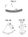
- Fig. 2 illustratively shows the configuration of the X-ray detector 24.
- the X-ray detector 24 is a multi-channel X-ray detector having a plurality of X-ray detector elements 24(ik) arranged in a two-dimensional array.
- the plurality of X-ray detector elements 24(ik) forms a cylindrically concave X-ray receiving surface as a whole.
- i denotes a channel number that is, for example, 1, 2, ⁇ ⁇ ⁇ , 1000
- k denotes a row number that is, for example, 1, 2, ..., 240.
- the X-ray detector elements 24(ik) having the same row number k constitute a detector element array.
- the number of detector element arrays constituting the X-ray detector 24 is not limited to 240 but may be any value.
- Each of the X-ray detector elements 24(ik) is realized with, for example, a combination of a scintillator and a photodiode.
- the present invention is not limited to this combination.
- a semiconductor X-ray detector element utilizing cadmium telluride or an ionization chamber type X-ray detector element utilizing a xenon gas may be adopted.
- Fig. 3 shows the correlation among the X-ray tube 20, collimator 22, and X-ray detector 24 that are included in the X-irradiation/detection equipment.
- the X-ray tube 20 is represented by X-ray focal spots.
- the X-ray focal spot may be simply called a focal spot.
- Fig. 3(a) shows the correlation observed in front of the scanner gantry 2
- Fig. 3(b) shows the correlation observed by the side of the scanner gantry 2.
- the X-ray tube 20 has two focal spots 202 and 204. X-rays radiated from the focal spots 202 and 204 are recomposed into two cone beam X-radiations 402 and 404 by means of the collimator 22, and then irradiated to the X-ray detector 24.
- Fig. 3(a) shows the spreads in one direction of the cone beam X-radiations 402 and 404.
- this direction may be called a width direction.
- the width direction of the cone beam X-radiations 402 and 404 corresponds to the direction in which channels are juxtaposed in the X-ray detector 24.
- Fig. 3(b) shows the spreads in other direction of the cone beam X-radiations 402 and 404.
- This direction may be called the thickness direction of the cone beam X-radiations 402 and 404.
- the thickness direction of the cone beam X-radiations 402 and 404 corresponds to a direction in which the plurality of detector element arrays is juxtaposed in the X-ray detector 24.
- a subject 8 is, for example, as shown in Fig. 4, carried into an X-irradiation space while lying down on the radiographic table 4 with his/her body axis intersecting the cone beam X-radiations 402 and 404.
- the scanner gantry 2 has a cylindrical structure in which the X-irradiation/detection equipment is incorporated.
- the X-irradiation space is defined in an internal space of the cylindrical structure of the scanner gantry 2.
- the cone beam X-radiations 402 and 404 pass through the subject 8 and fall on the X-ray detector 24.
- the X-ray detector 24 detects a two-dimensional distribution of intensities exhibited by the transmitted X-radiations.
- a plurality (for example, about 1000) of views of projection data is acquired during one scan.
- the acquisition of projection data is achieved by the system of the X-ray detector 24, data acquisition unit 26, and data acquisition buffer 64.
- Fig. 5 illustratively shows the relationship between the two cone beam X-radiations 402 and 404.
- Fig. 5 has an observer's eye located at the same position as Fig. 3(b) does.
- the two cone beam X-radiations 402 and 404 generated from the two focal spots 202 and 204 pass through successive slabs 422 and 442.
- the slabs 422 and 442 are two slabs succeeding in the body-axis direction.
- the X-ray tube 20 has the two X-ray generation spots (focal spots) in association with two slabs, and can therefore appropriately generate two cone beam X-radiations. Moreover, since the collimator supporting the two X-ray generation spots is included, the two cone beam X-radiations can be appropriately formed.
- each of the slabs 422 and 442 is set to a maximum value S (for example, 80 mm) permitting image reconstruction to be performed based on a cone beam algorithm without causing an artifact. Consequently, the overall thickness of the two slabs 422 and 442 comes to 2S (for example, 160 mm).
- the employment of two cone beam X-radiations passing through two successive slabs realizes a slab thickness that is twice as large as the conventional limit permissible for radiography.
- the slab thickness is an overall thickness of a slab or slabs on a plane containing an isocenter.
- X-rays having passed through the slab 422 are detected by X-ray detector elements belonging to a range A in the X-ray detector 24. Based on detection signals sent from the X-ray detector elements, an image representing the slab 422 is reconstructed according to a cone beam algorithm.
- X-rays having passed through the slab 442 are detected by X-ray detector elements belonging to a range B in the X-ray detector 24. Based on detection signals sent from the X-ray detection elements, an image representing the slab 442 is reconstructed according to the cone beam algorithm.
- the thickness of each of the slabs 422 and 452 is set to a value permitting image reconstruction to be performed based on the cone beam algorithm without causing an artifact. Therefore, a good-quality image can be reconstructed.
- the ranges A and B within which the cone beam X-radiations 402 and 404 are received overlap.
- the cone beam X-radiations 402 and 404 are therefore alternately irradiated as shown in the timing chart of Fig. 7 in order to avoid mixing of detection signals detected by the X-ray detector elements belonging to the overlapping parts of the ranges A and B.
- double radiography of parts of slabs can be avoided.
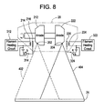
- Fig. 8 shows an example of a configuration including the X-ray tube 20 and control circuits that permit alternate X-irradiations.
- the X-ray tube 20 comprises a set of an anode 212, a cathode 214, and a grid 216 and a set of an anode 222, a cathode 224, and a grid 226.
- a filament current is fed to the cathode 214 or 224 by a filament heating circuit 312 or 322.
- a bias voltage is applied to the grid 216 or 226 after being set to either of two levels by a switch 322 or 324.
- the two levels to which the bias voltage is set are 0 V and a negative voltage.
- the negative voltage assumes a value permitting blocking of an electron flow between a cathode and an anode. Consequently, X-irradiation can be discontinued by changing the connections to be made via the switch 322 or 324.
- the connections to be made via the switch 322 or 324 are changed with either of signals that are out of phase with each other.
- the cone beam X-radiations 402 and 404 are alternately generated from the focal spots 202 and 204 respectively.
- two cone beam X-radiations can be appropriately generated. Since the X-ray tube includes two anodes and two cathodes in association with two slabs, two focal spots can be appropriately offered. Moreover, since the X-ray tube has two grids associated with the two pairs of an anode and a cathode, the timings of generating two cone beam X-radiations can be controlled.
- the best mode for implementing the present invention has been described in reference to an example in which the number of successive slabs is two.
- the number of successive slabs is not limited to two but may be any value equal to or larger than 2.
Abstract
Description
- The present invention relates to an X-ray computed tomography (CT) system and an X-ray apparatus. More particularly, the present invention is concerned with an X-ray CT system that scans a three-dimensional region with a cone beam X-radiation, and an X-ray apparatus for the X-ray CT system.
- In X-ray CT systems, a cone beam X-radiation is used to radiograph a three-dimensional region (slab) in a subject during one scan. A two-dimensional array detector detects a two-dimensional distribution of intensities exhibited by the cone beam X-radiation having passed through the slab (projection). An image is then reconstructed based on a plurality of views of projection data.
- A cone beam algorithm is used to reconstruct an image. A typical cone beam algorithm is a Feldkamp algorithm (refer to, for example, Japanese Unexamined Patent Application Publication No. 2003-144429 (p.4)).
- When any of cone beam algorithms represented by the Feldkamp algorithm is employed, a slab thickness permissible for radiography during one scan, that is, the size in a body-axis direction of a three-dimensional region is about 80 mm at maximum in practice. If the thickness is equal to or larger than 80 mm, image quality is degraded due to an increase in the number of artifacts in a reconstructed image.
- Therefore, an object of the present invention is to realize an X-ray CT system offering a large slab thickness permissible for radiography during one scan, and an X-ray apparatus for the X-ray CT system.
- (1) According to one aspect of the present invention for accomplishing the above object, there is provided an X-ray CT system comprising: an X-ray generating means for generating a plurality of cone beam X-radiations that passes through a plurality of successive slabs; an X-ray detecting means for detecting a two-dimensional distribution of intensities exhibited by cone beam X-radiations having passed through the plurality of slabs; an acquiring means for acquiring a plurality of views of projection data, which represents the plurality of slabs, on the basis of detection signals sent from the X-ray detecting means; and a reconstructing means for reconstructing an image according to the projection data.
- (2) According to another aspect of the present invention for accomplishing the aforesaid object, there is provided an X-ray apparatus comprising: an X-ray generating means for generating a plurality of cone beam X-radiations that passes through a plurality of successive slabs; and an X-ray detecting means for detecting a two-dimensional distribution of intensities exhibited by the plurality of cone beam X-radiations having passed through the plurality of slabs.
-
- Preferably, the plurality of cone beam X-radiations asynchronously passes through adjoining slabs from the viewpoint of avoiding overlap of projections of the slabs. Preferably, the X-ray generating means has X-ray generation spots in association with the plurality of slabs from the viewpoint of appropriately generating a plurality of cone beam X-radiations. Preferably, the X-ray generating means includes a collimator in association with the X-ray generation spots, from the viewpoint of appropriately forming a plurality of cone beam X-radiations.
- Preferably, the X-ray generating means includes an X-ray tube, which has a plurality of X-ray focal spots in association with the plurality of slabs, from the viewpoint of appropriately generating a plurality of cone beam X-radiations. Preferably, the X-ray tube includes a plurality of pairs of an anode and a cathode in association with the plurality of slabs from the viewpoint of appropriately offering a plurality of focal spots. Preferably, the X-ray tube has a plurality of grids associated with the plurality of pairs of an anode and a cathode from the viewpoint of controlling the timings of generating a plurality of cone beam X-radiations. Preferably, the number of successive slabs is two from the viewpoint of offering an overall slab thickness that is twice as large as the conventional one.
- According to the foregoing aspects of the present invention, the present invention includes the X-ray generating means for generating a plurality of cone beam X-radiations that passes through a plurality of successive slabs and the X-ray detecting means for detecting a two-dimensional distribution of intensities exhibited by the plurality of cone beam X-radiations having passed through the plurality of slabs. Therefore, while the thickness of each of the slabs is set to a value permitting image reconstruction based on a cone beam algorithm, the overall slab thickness, that is, the overall thickness of the plurality of slabs can be increased.
- Further objects and advantages of the present invention will be apparent from the following description of the preferred embodiments of the invention as illustrated in the accompanying drawings, in which:
- Fig. 1 is a block diagram of an X-ray CT system that is the best mode for implementing the present invention.
- Fig. 2 shows the configuration of an X-ray detector.
- Fig. 3 shows the configuration of X-irradiation/detection equipment.
- Fig. 4 shows the relationship between the X-irradiation/detection equipment and a subject.
- Fig. 5 shows the relationship between two cone beam X-radiations.
- Fig. 6 shows the relationship between two cone beam X-radiations.
- Fig. 7 shows the timings of irradiating two cone beam X-radiations.
- Fig. 8 shows the configuration of an X-ray tube having two focal spots.
-
- Referring to drawings, the best mode for implementing the present invention will be described below. Noted is that the present invention is not limited to the best mode for implementing the present invention. Fig. 1 is a block diagram of an X-ray CT system. The X-ray CT system is an example of the best mode for implementing the present invention. The configuration of the X-ray CT system provides an example of the best mode for implementing the present invention in an X-ray CT system. Moreover, part of the configuration of the X-ray CT system provides an example of the best mode for implementing the present invention in an X-ray apparatus.
- As shown in Fig. 1, the X-ray CT system comprises a
scanner gantry 2, a radiographic table 4, and anoperator console 6. Thescanner gantry 2 includes anX-ray tube 20. X-rays radiated from theX-ray tube 20 and not shown are recomposed or collimated into a conical X-ray beam or a cone beam X-radiation by acollimator 22, and then irradiated to anX-ray detector 24. The assembly of theX-ray tube 20 andcollimator 22 is an example of an X-ray generating means included in the present invention. TheX-ray tube 20 is an example of an X-ray tube included in the present invention. Thecollimator 22 is an example of a collimator included in the present invention. - The
X-ray detector 24 includes a plurality of detector elements arranged in a two-dimensional array along with the spread of a cone beam X-radiation. TheX-ray detector 24 is an example of an X-ray detecting means included in the present invention. The configuration of theX-ray detector 24 will be described later. A subject of radiography is carried into a space between theX-ray tube 20 andX-ray detector 24 while lying down on the radiographic table 4. - As described later, the
X-ray tube 20 has a plurality of focal spots and generates X-ray beams from the focal spots. Thecollimator 22 collimates the plurality of X-radiations. TheX-ray tube 20,collimator 22, andX-ray detector 24 constitute X-irradiation/detection equipment. The X-irradiation/detection equipment will be described later. - A
data acquisition unit 26 is connected to theX-ray detector 24. Thedata acquisition unit 26 acquires detection signals, which are sent from the respective detector elements included in theX-ray detector 24, in the form of digital data. TheX-ray detector 24 anddata acquisition unit 26 constitute an example of an acquiring means included in the present invention. The detection signals sent from the detector elements serve as a signal representing a projection of a subject produced with X-rays. The signal shall be called projection data or merely data. - X-irradiation from the
X-ray tube 20 is controlled by anX-ray controller 28. The illustration of the connective relationship between theX-ray tube 20 andX-ray controller 28 will be omitted. Thecollimator 22 is controlled by acollimator controller 30. The illustration of the connective relationship between thecollimator 22 andcollimator controller 30 will be omitted. - The foregoing components starting with the
X-ray tube 20 and ending with thecollimator controller 30 are incorporated in arotary drum 34 included in thescanner gantry 2, and can be rotated about a subject of radiography. The rotation of therotary drum 34 is controlled by arotation controller 36. The illustration of the connective relationship between therotary drum 34 androtation controller 36 will be omitted. - The
operator console 6 includes adata processing unit 60. Thedata processing unit 60 is realized with, for example, a computer. Acontrol interface 62 is connected to thedata processing unit 60. Thescanner gantry 2 and radiographic table 4 are connected to thecontrol interface 62. Thedata processing unit 60 controls thescanner gantry 2 and radiographic table 4 via thecontrol interface 62. - The
data acquisition unit 26,X-ray controller 28,collimator controller 30, androtation controller 36 incorporated in thescanner gantry 2 are controlled via thecontrol interface 62, whereby a subject of radiography is scanned. The illustration of the connections of these components to thecontrol interface 62 will be omitted. - A
data acquisition buffer 64 is connected to thedata processing unit 60. Thedata acquisition unit 26 incorporated in thescanner gantry 2 is connected to thedata acquisition buffer 64. Data acquired by thedata acquisition unit 26 is transferred to thedata processing unit 60 via thedata acquisition buffer 64. - A
storage device 66 is connected to thedata processing unit 60. Projection data transferred to thedata processing unit 60 via thedata acquisition buffer 64 andcontrol interface 62 is stored in thestorage device 66. Moreover, programs for giving instructions to thedata processing unit 60 are stored in thestorage device 66. Thedata processing unit 60 runs any of the programs, whereby an action is performed in the X-ray CT system. - The
data processing unit 60 reconstructs an image using a plurality of views of projection data that is stored in thestorage device 66 via thedata acquisition buffer 64. Thedata processing unit 60 is an example of a reconstructing means included in the present invention. For image reconstruction, a cone beam algorithm, for example, a Feldkamp algorithm is employed. - A
display device 68 and an operatingdevice 70 are connected to thedata processing unit 60. Thedisplay device 68 is realized with a graphic display or the like. The operatingdevice 70 is realized with a keyboard having a pointing device. - A reconstructed image sent from the
data processing unit 60 and other information are displayed on thedisplay device 68. A user manipulates the operatingunit 70 so as to enter various instructions or pieces of information that are transmitted to thedata processing unit 60. The user uses thedisplay device 68 andoperating device 70 to interactively operate the X-ray CT system. - Fig. 2 illustratively shows the configuration of the
X-ray detector 24. As illustrated, theX-ray detector 24 is a multi-channel X-ray detector having a plurality of X-ray detector elements 24(ik) arranged in a two-dimensional array. The plurality of X-ray detector elements 24(ik) forms a cylindrically concave X-ray receiving surface as a whole. - Herein, i denotes a channel number that is, for example, 1, 2, · · · , 1000, and k denotes a row number that is, for example, 1, 2, ..., 240. The X-ray detector elements 24(ik) having the same row number k constitute a detector element array. The number of detector element arrays constituting the
X-ray detector 24 is not limited to 240 but may be any value. - Each of the X-ray detector elements 24(ik) is realized with, for example, a combination of a scintillator and a photodiode. The present invention is not limited to this combination. Alternatively, a semiconductor X-ray detector element utilizing cadmium telluride or an ionization chamber type X-ray detector element utilizing a xenon gas may be adopted.
- Fig. 3 shows the correlation among the
X-ray tube 20,collimator 22, andX-ray detector 24 that are included in the X-irradiation/detection equipment. In the drawing, theX-ray tube 20 is represented by X-ray focal spots. Hereinafter, the X-ray focal spot may be simply called a focal spot. Fig. 3(a) shows the correlation observed in front of thescanner gantry 2, while Fig. 3(b) shows the correlation observed by the side of thescanner gantry 2. - As illustrated, the
X-ray tube 20 has twofocal spots focal spots cone beam X-radiations collimator 22, and then irradiated to theX-ray detector 24. - Fig. 3(a) shows the spreads in one direction of the
cone beam X-radiations cone beam X-radiations X-ray detector 24. Fig. 3(b) shows the spreads in other direction of thecone beam X-radiations cone beam X-radiations cone beam X-radiations X-ray detector 24. - A subject 8 is, for example, as shown in Fig. 4, carried into an X-irradiation space while lying down on the radiographic table 4 with his/her body axis intersecting the
cone beam X-radiations scanner gantry 2 has a cylindrical structure in which the X-irradiation/detection equipment is incorporated. The X-irradiation space is defined in an internal space of the cylindrical structure of thescanner gantry 2. Thecone beam X-radiations subject 8 and fall on theX-ray detector 24. TheX-ray detector 24 detects a two-dimensional distribution of intensities exhibited by the transmitted X-radiations. - When the X-irradiation/detection equipment is rotated with the radiographic table 4 at a halt, an axial scan is achieved. When the radiographic table 4 is, as indicated with an
arrow 42, continuously moved in the direction of the body axis of the subject 8 concurrently with the rotation of the X-irradiation/detection equipment, the X-irradiation/detection equipment follows a helical trajectory, which encloses the subject 8, relatively to the subject. Consequently, a so-called helical scan is achieved. - A plurality (for example, about 1000) of views of projection data is acquired during one scan. The acquisition of projection data is achieved by the system of the
X-ray detector 24,data acquisition unit 26, anddata acquisition buffer 64. - The two
cone beam X-radiations cone beam X-radiations cone beam X-radiations focal spots successive slabs slabs - The
X-ray tube 20 has the two X-ray generation spots (focal spots) in association with two slabs, and can therefore appropriately generate two cone beam X-radiations. Moreover, since the collimator supporting the two X-ray generation spots is included, the two cone beam X-radiations can be appropriately formed. - The thickness of each of the
slabs slabs - The employment of two cone beam X-radiations passing through two successive slabs realizes a slab thickness that is twice as large as the conventional limit permissible for radiography. The slab thickness is an overall thickness of a slab or slabs on a plane containing an isocenter.
- X-rays having passed through the
slab 422 are detected by X-ray detector elements belonging to a range A in theX-ray detector 24. Based on detection signals sent from the X-ray detector elements, an image representing theslab 422 is reconstructed according to a cone beam algorithm. X-rays having passed through theslab 442 are detected by X-ray detector elements belonging to a range B in theX-ray detector 24. Based on detection signals sent from the X-ray detection elements, an image representing theslab 442 is reconstructed according to the cone beam algorithm. The thickness of each of theslabs 422 and 452 is set to a value permitting image reconstruction to be performed based on the cone beam algorithm without causing an artifact. Therefore, a good-quality image can be reconstructed. - Other advantage provided by the employment of two
cone beam X-radiations X-ray detector 24 is small for an increase in a slab thickness. Namely, supposing slabs having the same thickness are radiographed with a sole cone beam X-radiation, since the sole cone beam X-radiation spreads, the light receiving surface of theX-ray detector 24 must be larger than it is when two cone beam X-radiations are employed. Therefore, the X-ray detector cannot help being designed to be large in size. - The ranges A and B within which the
cone beam X-radiations cone beam X-radiations - Fig. 8 shows an example of a configuration including the
X-ray tube 20 and control circuits that permit alternate X-irradiations. As shown in Fig. 8, theX-ray tube 20 comprises a set of ananode 212, acathode 214, and agrid 216 and a set of ananode 222, acathode 224, and agrid 226. - A filament current is fed to the
cathode filament heating circuit grid switch - The two levels to which the bias voltage is set are 0 V and a negative voltage. The negative voltage assumes a value permitting blocking of an electron flow between a cathode and an anode. Consequently, X-irradiation can be discontinued by changing the connections to be made via the
switch switch cone beam X-radiations focal spots - As mentioned above, since an X-ray tube having two X-ray focal spots in association with two slabs is employed, two cone beam X-radiations can be appropriately generated. Since the X-ray tube includes two anodes and two cathodes in association with two slabs, two focal spots can be appropriately offered. Moreover, since the X-ray tube has two grids associated with the two pairs of an anode and a cathode, the timings of generating two cone beam X-radiations can be controlled.
- The best mode for implementing the present invention has been described in reference to an example in which the number of successive slabs is two. The number of successive slabs is not limited to two but may be any value equal to or larger than 2.
Claims (10)
- An X-ray CT system comprising:an X-ray generating device (20) for generating a plurality of cone beam X-radiations that passes through a plurality of successive slabs (422, 442);an X-ray detecting device (24) for detecting a two-dimensional distribution of intensities exhibited by the plurality of cone beam X-radiations having passed through the plurality of slabs (422, 442);an acquiring device (26, 64) for acquiring a plurality of views of projection data, which represents the plurality of slabs (422, 442), on the basis of detection signals sent from said X-ray detecting device (24); anda reconstructing device (60) for reconstructing an image according to the projection data.
- An X-ray CT system according to Claim 1, wherein the plurality of cone beam X-radiations asynchronously passes through adjoining slabs (422, 442).
- An X-ray CT system according to Claim 1 or 2, wherein said X-ray generating device (20) has X-ray generation spots in association with the plurality of slabs (422, 442).
- An X-ray CT system according to Claim 3, wherein said X-ray generating device (20) includes a collimator (22) that supports the X-ray generation spots.
- An X-ray CT system according to any of Claims 1 to 4, wherein said X-ray generating device (20) includes an X-ray tube (20) that has a plurality of X-ray focal spots in association with the plurality of slabs (422, 442).
- An X-ray CT system according to Claim 5, wherein said X-ray tube (20) includes a plurality of pairs of an anode (212, 222) and a cathode (214, 224) in association with the plurality of slabs (422, 442).
- An X-ray CT system according to Claim 6, wherein said X-ray tube (20) has a plurality of grids (216, 226) associated with said plurality of pairs of an anode (212, 222) and a cathode (214, 224).
- An X-ray CT system according to any of Claims 1 to 7, wherein the number of successive slabs (422, 442) is two.
- An X-ray apparatus comprising:an X-ray generating device (20) for generating a plurality of cone beam X-radiations that passes through a plurality of successive slabs (422, 442); andan X-ray detecting device (24) for detecting a two-dimensional distribution of intensities exhibited by the plurality of cone beam X-radiations having passed through the plurality of slabs (422, 442).
- An X-ray apparatus according to Claim 9, wherein the plurality of cone beam X-radiations asynchronously passes through adjoining slabs (422, 442).
Applications Claiming Priority (2)
| Application Number | Priority Date | Filing Date | Title |
|---|---|---|---|
| JP2004057154A JP2005245559A (en) | 2004-03-02 | 2004-03-02 | X-ray ct apparatus and x-ray device |
| JP2004057154 | 2004-03-02 |
Publications (1)
| Publication Number | Publication Date |
|---|---|
| EP1570785A1 true EP1570785A1 (en) | 2005-09-07 |
Family
ID=34747615
Family Applications (1)
| Application Number | Title | Priority Date | Filing Date |
|---|---|---|---|
| EP05251140A Withdrawn EP1570785A1 (en) | 2004-03-02 | 2005-02-25 | X-ray ct system and x-ray apparatus |
Country Status (5)
| Country | Link |
|---|---|
| US (1) | US7203268B2 (en) |
| EP (1) | EP1570785A1 (en) |
| JP (1) | JP2005245559A (en) |
| KR (1) | KR20060043244A (en) |
| CN (1) | CN1663533A (en) |
Cited By (7)
| Publication number | Priority date | Publication date | Assignee | Title |
|---|---|---|---|---|
| WO2006038145A1 (en) | 2004-10-06 | 2006-04-13 | Philips Intellectual Property & Standards Gmbh | Computed tomography method |
| WO2006135837A1 (en) * | 2005-06-10 | 2006-12-21 | Xoran Technologies, Inc. | Multiple source ct scanner |
| US7206373B2 (en) | 2004-07-30 | 2007-04-17 | Siemens Aktiengesellschaft | Computed tomography gantry |
| WO2008122970A1 (en) * | 2007-04-10 | 2008-10-16 | Arineta Ltd. | X-ray tube plurality of targets and corresponding number of electron beam gates |
| US7869561B2 (en) | 2007-04-10 | 2011-01-11 | Arineta Ltd. | Cone-beam CT |
| CN101291624B (en) * | 2005-10-18 | 2011-10-19 | 皇家飞利浦电子股份有限公司 | Patient scan time optimization for pet/spect imaging |
| US8537965B2 (en) | 2007-04-10 | 2013-09-17 | Arineta Ltd. | Cone-beam CT |
Families Citing this family (20)
| Publication number | Priority date | Publication date | Assignee | Title |
|---|---|---|---|---|
| US7646842B2 (en) * | 2005-09-23 | 2010-01-12 | General Electric Company | Methods and apparatus for reconstructing thick image slices |
| US7746974B2 (en) * | 2006-09-29 | 2010-06-29 | Siemens Medical Solutions Usa, Inc. | Radiographic and fluoroscopic CT imaging |
| JP5295503B2 (en) * | 2007-01-15 | 2013-09-18 | ジーイー・メディカル・システムズ・グローバル・テクノロジー・カンパニー・エルエルシー | X-ray generator and X-ray CT apparatus |
| US7852979B2 (en) * | 2007-04-05 | 2010-12-14 | General Electric Company | Dual-focus X-ray tube for resolution enhancement and energy sensitive CT |
| JP4935581B2 (en) * | 2007-08-24 | 2012-05-23 | 株式会社島津製作所 | X-ray diagnostic equipment |
| US8180017B2 (en) * | 2007-12-20 | 2012-05-15 | Koninklijke Philips Electronics N.V. | Stereo tube attenuation filter |
| JP5398157B2 (en) * | 2008-03-17 | 2014-01-29 | キヤノン株式会社 | X-ray imaging apparatus and control method thereof |
| US7949089B2 (en) * | 2008-04-10 | 2011-05-24 | Arineta Ltd. | Apparatus and method for tracking feature's position in human body |
| JP5159543B2 (en) * | 2008-09-30 | 2013-03-06 | 株式会社東芝 | X-ray CT system |
| US20100080357A1 (en) * | 2008-10-01 | 2010-04-01 | General Electric Company | Wide coverage x-ray tube and ct system |
| US8027433B2 (en) * | 2009-07-29 | 2011-09-27 | General Electric Company | Method of fast current modulation in an X-ray tube and apparatus for implementing same |
| US8396185B2 (en) | 2010-05-12 | 2013-03-12 | General Electric Company | Method of fast current modulation in an X-ray tube and apparatus for implementing same |
| US20110299653A1 (en) * | 2010-12-15 | 2011-12-08 | General Electric Company | Method and apparatus for laminography inspection |
| CN103892855A (en) * | 2012-12-28 | 2014-07-02 | 上海联影医疗科技有限公司 | Digital medical image processing method and device |
| DE102013203541A1 (en) * | 2013-03-01 | 2014-09-04 | Siemens Aktiengesellschaft | X-ray CT scan and dual source CT system |
| US10251613B2 (en) | 2013-03-01 | 2019-04-09 | Siemens Healthcare Gmbh | X-ray CT scanning and dual-source CT system |
| JP5961775B2 (en) * | 2013-05-08 | 2016-08-02 | コーニンクレッカ フィリップス エヌ ヴェKoninklijke Philips N.V. | Collimation for distant focus |
| CN110676145A (en) * | 2019-10-30 | 2020-01-10 | 深圳市安健科技股份有限公司 | Multi-focus X-ray bulb tube and multi-focus X-ray imaging system |
| WO2023082232A1 (en) * | 2021-11-15 | 2023-05-19 | Shenzhen Xpectvision Technology Co., Ltd. | Apparatus and method for x-ray fluorescence imaging |
| CN114886444B (en) * | 2022-07-14 | 2022-11-08 | 有方(合肥)医疗科技有限公司 | CBCT imaging reconstruction method |
Citations (5)
| Publication number | Priority date | Publication date | Assignee | Title |
|---|---|---|---|---|
| US4349740A (en) * | 1976-12-23 | 1982-09-14 | Siemens Aktiengesellschaft | Apparatus for displaying fluoroscopic tomographic images of the body |
| US5825842A (en) * | 1995-07-05 | 1998-10-20 | Kabushiki Kaisha Toshiba | X-ray computed tomographic imaging device and x-ray computed tomographic method |
| EP1005257A2 (en) * | 1998-11-25 | 2000-05-31 | Picker International, Inc. | Computed tomography |
| US6118839A (en) * | 1991-07-24 | 2000-09-12 | Elscint Ltd. | Multiple slice CT scanner |
| US20030108146A1 (en) * | 2000-09-28 | 2003-06-12 | Gabriel Malamud | CT scanner for time-coherent large coverage |
Family Cites Families (8)
| Publication number | Priority date | Publication date | Assignee | Title |
|---|---|---|---|---|
| DE19845133A1 (en) | 1998-10-01 | 2000-04-06 | Philips Corp Intellectual Pty | Computed tomography procedure with a conical beam |
| US6256366B1 (en) | 1999-07-22 | 2001-07-03 | Analogic Corporation | Apparatus and method for reconstruction of volumetric images in a computed tomography system using sementation of slices |
| US6201849B1 (en) | 1999-08-16 | 2001-03-13 | Analogic Corporation | Apparatus and method for reconstruction of volumetric images in a helical scanning cone-beam computed tomography system |
| US6256365B1 (en) | 1999-08-16 | 2001-07-03 | Analogic Corporation | Apparatus and method for reconstruction of images in a computed tomography system using oblique slices |
| US6560308B1 (en) | 2001-10-26 | 2003-05-06 | Kabushiki Kaisha Toshiba | Method and system for approximating missing data in cone beam x-ray CT reconstruction |
| JP2003203797A (en) | 2002-01-09 | 2003-07-18 | Rumio Yuki | X-ray high voltage device, and radiographic apparatus provided with the same |
| US7042975B2 (en) * | 2002-10-25 | 2006-05-09 | Koninklijke Philips Electronics N.V. | Four-dimensional helical tomographic scanner |
| US7187748B2 (en) * | 2003-12-30 | 2007-03-06 | Ge Medical Systems Global Technology Company, Llc | Multidetector CT imaging method and apparatus with reducing radiation scattering |
-
2004
- 2004-03-02 JP JP2004057154A patent/JP2005245559A/en active Pending
-
2005
- 2005-02-25 EP EP05251140A patent/EP1570785A1/en not_active Withdrawn
- 2005-02-28 KR KR1020050016529A patent/KR20060043244A/en not_active Application Discontinuation
- 2005-03-01 US US11/069,850 patent/US7203268B2/en not_active Expired - Fee Related
- 2005-03-02 CN CN2005100530352A patent/CN1663533A/en active Pending
Patent Citations (5)
| Publication number | Priority date | Publication date | Assignee | Title |
|---|---|---|---|---|
| US4349740A (en) * | 1976-12-23 | 1982-09-14 | Siemens Aktiengesellschaft | Apparatus for displaying fluoroscopic tomographic images of the body |
| US6118839A (en) * | 1991-07-24 | 2000-09-12 | Elscint Ltd. | Multiple slice CT scanner |
| US5825842A (en) * | 1995-07-05 | 1998-10-20 | Kabushiki Kaisha Toshiba | X-ray computed tomographic imaging device and x-ray computed tomographic method |
| EP1005257A2 (en) * | 1998-11-25 | 2000-05-31 | Picker International, Inc. | Computed tomography |
| US20030108146A1 (en) * | 2000-09-28 | 2003-06-12 | Gabriel Malamud | CT scanner for time-coherent large coverage |
Cited By (9)
| Publication number | Priority date | Publication date | Assignee | Title |
|---|---|---|---|---|
| US7206373B2 (en) | 2004-07-30 | 2007-04-17 | Siemens Aktiengesellschaft | Computed tomography gantry |
| DE102004037076B4 (en) * | 2004-07-30 | 2011-02-24 | Siemens Ag | Gantry and computed tomography |
| WO2006038145A1 (en) | 2004-10-06 | 2006-04-13 | Philips Intellectual Property & Standards Gmbh | Computed tomography method |
| WO2006135837A1 (en) * | 2005-06-10 | 2006-12-21 | Xoran Technologies, Inc. | Multiple source ct scanner |
| CN101291624B (en) * | 2005-10-18 | 2011-10-19 | 皇家飞利浦电子股份有限公司 | Patient scan time optimization for pet/spect imaging |
| WO2008122970A1 (en) * | 2007-04-10 | 2008-10-16 | Arineta Ltd. | X-ray tube plurality of targets and corresponding number of electron beam gates |
| US7869561B2 (en) | 2007-04-10 | 2011-01-11 | Arineta Ltd. | Cone-beam CT |
| US8537965B2 (en) | 2007-04-10 | 2013-09-17 | Arineta Ltd. | Cone-beam CT |
| US8693638B2 (en) | 2007-04-10 | 2014-04-08 | Arineta Ltd. | X-ray tube |
Also Published As
| Publication number | Publication date |
|---|---|
| US20050195935A1 (en) | 2005-09-08 |
| CN1663533A (en) | 2005-09-07 |
| JP2005245559A (en) | 2005-09-15 |
| US7203268B2 (en) | 2007-04-10 |
| KR20060043244A (en) | 2006-05-15 |
Similar Documents
| Publication | Publication Date | Title |
|---|---|---|
| US7203268B2 (en) | X-ray CT system and X-ray apparatus | |
| US7945014B2 (en) | X-ray system and method for tomosynthetic scanning | |
| US6229870B1 (en) | Multiple fan beam computed tomography system | |
| JP3909048B2 (en) | X-ray CT apparatus and X-ray tube | |
| EP2002789B1 (en) | X-Ray scanning system | |
| US7460635B2 (en) | X-ray CT apparatus, method of controlling the same, and program | |
| US6041097A (en) | Method and apparatus for acquiring volumetric image data using flat panel matrix image receptor | |
| US9675306B2 (en) | X-ray scanning system | |
| EP1959835B1 (en) | Systems and methods for scanning and data acquisition in computed tomography (ct) applications | |
| US8983024B2 (en) | Tetrahedron beam computed tomography with multiple detectors and/or source arrays | |
| US10709408B2 (en) | Medical image diagnosis apparatus and control method | |
| JP2005080919A (en) | Radiation tomograph apparatus | |
| JP2002200068A (en) | System and method for radiation tomographic imaging | |
| JP2009125250A (en) | X-ray ct equipment | |
| JP2008012206A (en) | X-ray tomographic apparatus | |
| JP7179479B2 (en) | X-ray CT device | |
| JP2005204707A (en) | X-ray ct system and image pickup method | |
| JP3950612B2 (en) | X-ray CT system | |
| JP2006255241A (en) | Radiography method and radiography equipment | |
| JP2004208799A (en) | Transmission x-rays data acquiring apparatus and x-ray ct apparatus | |
| JP3796378B2 (en) | X-ray CT system | |
| JP7391633B2 (en) | X-ray imaging device and X-ray generator | |
| JP5823178B2 (en) | X-ray CT system | |
| JP7433809B2 (en) | Trained model generation method and medical processing device | |
| US20230404493A1 (en) | X-ray ct apparatus, correction data collection method, and storage medium |
Legal Events
| Date | Code | Title | Description |
|---|---|---|---|
| PUAI | Public reference made under article 153(3) epc to a published international application that has entered the european phase |
Free format text: ORIGINAL CODE: 0009012 |
|
| AK | Designated contracting states |
Kind code of ref document: A1 Designated state(s): AT BE BG CH CY CZ DE DK EE ES FI FR GB GR HU IE IS IT LI LT LU MC NL PL PT RO SE SI SK TR |
|
| AX | Request for extension of the european patent |
Extension state: AL BA HR LV MK YU |
|
| 17P | Request for examination filed |
Effective date: 20060307 |
|
| AKX | Designation fees paid |
Designated state(s): DE FR GB NL |
|
| 17Q | First examination report despatched |
Effective date: 20061006 |
|
| STAA | Information on the status of an ep patent application or granted ep patent |
Free format text: STATUS: THE APPLICATION IS DEEMED TO BE WITHDRAWN |
|
| 18D | Application deemed to be withdrawn |
Effective date: 20080916 |