EP1574404B1 - Airbag structure - Google Patents
Airbag structure Download PDFInfo
- Publication number
- EP1574404B1 EP1574404B1 EP05005141A EP05005141A EP1574404B1 EP 1574404 B1 EP1574404 B1 EP 1574404B1 EP 05005141 A EP05005141 A EP 05005141A EP 05005141 A EP05005141 A EP 05005141A EP 1574404 B1 EP1574404 B1 EP 1574404B1
- Authority
- EP
- European Patent Office
- Prior art keywords
- panels
- panel
- yarns
- airbag
- fabric
- Prior art date
- Legal status (The legal status is an assumption and is not a legal conclusion. Google has not performed a legal analysis and makes no representation as to the accuracy of the status listed.)
- Not-in-force
Links
Images


Classifications
-
- B—PERFORMING OPERATIONS; TRANSPORTING
- B60—VEHICLES IN GENERAL
- B60R—VEHICLES, VEHICLE FITTINGS, OR VEHICLE PARTS, NOT OTHERWISE PROVIDED FOR
- B60R21/00—Arrangements or fittings on vehicles for protecting or preventing injuries to occupants or pedestrians in case of accidents or other traffic risks
- B60R21/02—Occupant safety arrangements or fittings, e.g. crash pads
- B60R21/16—Inflatable occupant restraints or confinements designed to inflate upon impact or impending impact, e.g. air bags
- B60R21/23—Inflatable members
- B60R21/231—Inflatable members characterised by their shape, construction or spatial configuration
-
- B—PERFORMING OPERATIONS; TRANSPORTING
- B60—VEHICLES IN GENERAL
- B60R—VEHICLES, VEHICLE FITTINGS, OR VEHICLE PARTS, NOT OTHERWISE PROVIDED FOR
- B60R21/00—Arrangements or fittings on vehicles for protecting or preventing injuries to occupants or pedestrians in case of accidents or other traffic risks
- B60R21/02—Occupant safety arrangements or fittings, e.g. crash pads
- B60R21/16—Inflatable occupant restraints or confinements designed to inflate upon impact or impending impact, e.g. air bags
- B60R21/23—Inflatable members
- B60R21/235—Inflatable members characterised by their material
- B60R2021/23533—Inflatable members characterised by their material characterised by the manufacturing process
-
- B—PERFORMING OPERATIONS; TRANSPORTING
- B60—VEHICLES IN GENERAL
- B60R—VEHICLES, VEHICLE FITTINGS, OR VEHICLE PARTS, NOT OTHERWISE PROVIDED FOR
- B60R21/00—Arrangements or fittings on vehicles for protecting or preventing injuries to occupants or pedestrians in case of accidents or other traffic risks
- B60R21/02—Occupant safety arrangements or fittings, e.g. crash pads
- B60R21/16—Inflatable occupant restraints or confinements designed to inflate upon impact or impending impact, e.g. air bags
- B60R21/23—Inflatable members
- B60R21/239—Inflatable members characterised by their venting means
Definitions
- the present invention relates to an airbag cushion comprising a front panel and a rear panel, wherein each of said front and rear panels has a non-circular configuration, wherein each of said panels comprises generally perpendicularly arranged sets of yarns, and wherein the yarns in the front panel are at a bias to the yarns in the rear panel.
- an airbag is known from GB 2 390 574 .
- the present invention also relates to a method of making an airbag comprising the steps of: providing first and second fabric panels having a non-circular geometrical configuration, orienting the panels such that at least one yarn in one of the panels is at a bias to at least one yarn in the other panel, and securing the panels to form an airbag.
- Driver side airbags are typically made from circular shaped panels so that when inflated, the airbag is symmetrical to provide thorough protection for the occupant in case of vehicular accident.
- the airbags also typically include internal tethers to control the excursion of the leading edge panel and help to provide the desired depth when inflated.
- the circular shaped front and back panels do not nest well on a given width of fabric and as a result, the nesting efficiency is not very good. For example, typical driver airbag nesting efficiency ranges between 80 and 85%, even though the rest of the bag components (such as the tethers and reinforcements) are nested in the space created between the circular pieces.
- the inventor hereof has previously proposed polygonal shaped bag panels (front and rear) having more than five sides, in order to improve the efficiency of the nest.
- panels with about five sides or greater end up approximating the shape of a circle, and therefore have some of the drawbacks of the circular bags.
- the present invention relates to an airbag as initially described and is characterised in that said airbag cushion further comprising a peripheral side panel extending between the front panel and rear panel.
- a peripheral side panel extending between the front panel and rear panel.
- panels having a shape not approximating a circle With generally non-circular panels is meant panels having a shape not approximating a circle.
- the present invention also relates to a method of making an airbag as initially described and is characterised in that said step of securing the panels to form an airbag comprises securing the peripheries of the first an second woven fabric panels to an intermediate side band forming panel.
- the panels will contain lengthwise and cross wise yarns, and the lengthwise and crosswise yarns in the respective panels are arranged at a bias to each other.
- the panels will be polygon-shaped and will have three to four sides.
- the construction of this invention enables greater nesting efficiency than previously achieved by comparable airbags using round panels.
- the construction enables the airbag to take full advantage of the strength of the yarns forming the fabric, and the energy absorption of the fabric, enabling the use of lower tenacity yarns at comparable levels of performance.
- bags made according to the invention can also be made from other materials, including but not limited to warp or weft laid fabrics, weft inserted warp knit fabrics, weft inserted fabrics, needlepunched fabrics, or the like, provided such fabrics have directionality in the lengthwise (e.g. warp) and crosswise (e.g. filling) directions. Therefore, where reference herein is made to the warp and filling directions, it is to be understood that those are likewise intended to encompass the corresponding lengthwise and crosswise extending yarns of other forms of fabric constructions described herein.
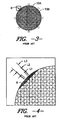
- Fig. 1 is an illustration of a nesting arrangement for round panels 10 used to make prior art round airbag constructions, illustrating how they would be cut from a piece of fabric F. As illustrated, this construction only enables about an 85% or less nesting efficiency (defined as the square meters or yards of fabric forming the panels divided by the total square meters or yards of fabric required for those panels to be provided.)
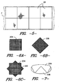
- Figs. 2A and 2B illustrate cut panels used to form the conventional round airbags.
- two circular panels 10A, 10B are cut (defining front and rear panels), and in this case, they are rotated 45 degrees relative to each other so that fabric elongation can be optimized.
- woven fabrics have the greatest elongation in a bias direction, rather than in the direction of the warp and filling yarns.
- bias angles could be used within the scope of the invention.
- the angle will range from about 27° to about 65°.
- Fig. 5 illustrates a nesting arrangement for square- shaped panels 20 that can be used in one embodiment of the invention.
- a nesting efficiency approximating 100% can be achieved, since the straight sides of the squares can fit directly next to each other.
- the width of the fabric used is a multiple of the widthwise dimension of the squares
- substantially 100% of the fabric can be utilized.
- the fabric used is of a width greater than a multiple of the width of the square panels, it would still be considered to achieve 100% nesting efficiency, since the surplus fabric would be a result of the fabric width rather than an inefficient nesting of the panels.
- first and second square panels 20A, 20B are cut from a woven fabric such that the warp and filling yarns run, generally parallel to the panel edges. These panels define the front and rear panels of the airbag. One of the panels is turned at an angle relative to the other (as shown in Fig. 6C ), such that the yarns in the front panel are at a bias to the yarns in the rear panel. In this embodiment, the peripheries of the two panels are seamed together. As illustrated, this results in a three dimensional structure having a seam that zig-zags around the periphery, as shown in Fig. 7 .
- Fig. 9 illustrates an alternative embodiment of the invention, which can be made utilizing generally square-shaped panels having rounded corners 32 such as those shown at 30. As shown, the panels 30 of this embodiment can also have concave side portions 34 if desired. It has been found that this modified square shape facilitates sewing of the panels together, since no sharp corners must be seamed. A nesting arrangement for panels made according to this embodiment is shown in Fig. 8 .
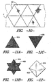
- Fig 10 shows a further alternative nesting arrangement for a plurality of triangular shaped panels 40A, 40B.
- Figs. 11A and 11B show the triangular panels 40A, 40B after they are removed from the fabric F, with Fig. 11C showing how the panels are oriented relative to each other prior to seaming the panels together.
- the warp or filling yarns will run parallel to one triangle edge, and the panels are positioned relative to each other such that the yarns are positioned at a bias relative to each other.
- Fig. 12 illustrates the airbag made using the panels 40A and 40B shown in Figs. 11A, 11B and 11C . As shown, the structure is in three-dimensional form as-seamed (i.e. prior to inflation.)
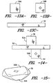
- Figs 13 A, 13B and 13C show panels that can be used to make a further alternative embodiment of the invention.
- This embodiment is similar to that shown in Figs. 6 and 7 , yet it includes an intermediate strip-like panel between the front and rear panels, which enables a bag having a comparable inflated volume to be achieved from smaller front and rear panels. As a result, greater nesting efficiency may be achieved.
- first and second four-sided panels 50A and 50B are cut as described above with respect to Fig. 6 .
- an additional fabric panel 52 is provided intermediate the front and rear panels.
- the front and rear panels 50A, 50B are positioned such that the yarns in one are at a bias relative to the yarns in the other, but rather than the panels being joined directly together, the peripheral side panel 52 is seamed between the two. In this way, additional three dimensionality can be readily provided. This can be accomplished by offsetting the front and rear panel-forming pieces in the manner shown in the figure, and seaming corner 54 of panel 50B to a central region 56 of panel 50A, then seaming around the entire periphery in the manner performed with respect to Figs. 6 and 7 , thereby securing panel 52 between the front and rear panels along the seam. The resulting bag is illustrated in Fig. 15 .
- Fig. 16 illustrates a weft inserted warp knit fabric 60 that can be used to form bags according to the invention.
- the fabric includes generally lengthwise extending yarns 62 and 64, and cross-wise extending yarns 66 which extend generally perpendicular to the longitudinally extending yarns 62 and 64.
- the yarns 62, 64, and 66 in the front panel will be oriented at a bias relative to the yarns of the rear panel.
- Fig. 17 illustrates an alternative fabric construction that may be used to form airbag cushions according to the invention.
- This fabric 70 has lengthwise extending warp yarns 72 as well as generally lengthwise extending yarns 74.
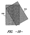
- Fig. 18 illustrates a further alternative embodiment of the invention.
- generally rectangular shaped panels 80A and 80B are utilized to create a generally rectangular shaped airbag. These panels will be joined together in the manner described above with respect to the square and triangular shaped bags.
- the bag constructions of the invention can be used in any airbag.
- the construction described provides a number of advantages over the constructions of prior airbags. For example, the weak spots inherent in the prior circular airbags are avoided.
- the bags are formed with a three-dimensional shape (as opposed to the two dimensional shape of the circular airbags prior to inflation), bags can be made to have equivalent volumes using smaller dimensions of fabric. For example, a conventional 54 liter circular airbag will generally require panels that are 71 cm (28 inches) in diameter, to accommodate the loss in diameter that occurs when the bag is inflated.
- the constructions of the invention can be made of any fabric or material that provides the requisite properties, and can be coated, laminated, or the like if so desired.
- airbags commonly are made from nylon 6-6.
- Other yarns and fibers include but are not limited to polyester fibers, nylon 6 fibers, other synthetic fibers, natural fibers or blend thereof, spun yarns, mono-filament yarns, multifilament yarns, etc. at any desired denier.
- the fabrics and bags can also include coatings and/or films including but not limited to polyurethanes, polyetherurethanes, polypropylenes, polyesterurethanes, polypropylenes, polyamides, ethylenevinylacetates, polyesters, etc.
- the method of the invention involves providing first and second fabric panels having a non-circular geometrical configuration, wherein said panels comprise generally perpendicularly intersecting lengthwise and cross-wise extending yarns.
- the panels are then secured together (either directly or via a side banding piece) such that the yarns in the front panel are at a bias to the yarns in the rear panel.
- the seaming can be performed in any conventional manner, but desirably is performed by sewing. However, other methods such as welding, adhesive attachment, ultrasonic sealing, etc., and combinations thereof, can be utilized within the scope of the invention.
- Airbags were manufactured as described below. All were made from a fabric of the variety used in conventional airbags (plain woven uncoated fabric having 41 ends per 2.54 cm (inch) and 41 picks per 2.54 cm (inch), woven from 630 denier nylon 6-6 yarns.)
- the bags with tethers had a 28 cm (11 inch) long tether made from the same type of fabric as the bag panels, attached in a conventional manner.
- the bags with tethers were checked for the inflated volume and were found to be 54 ⁇ 2 liters at 1 Psi internal bag pressure.
- the bag burst test procedure was a modified version of the ISO bag burst pressure procedure, described in a publication entitled "Bag Burst Test Procedure" published by Autoliv on August 10, 1994, test serial no. SO44, which is readily available and known by those of ordinary skill in the art.
- a test tank was pressurized to 125 Psi and an orifice plate with one 10 cm (4-inch) hole was used to mimic the gas flow rate from the inflator. Vents in the bags were plugged for testing with the same material as the bag. Plugs were sewn on the inside of the back panel to ensure that the vent hole was completely covered and sewn shut.
- the maximum pressure in the bag was recorded within 120 milliseconds of firing the inflation tank. Typical driver airbags of volume less than 62 liters would be burst under these conditions.
Abstract
Description
- The present invention relates to an airbag cushion comprising a front panel and a rear panel, wherein each of said front and rear panels has a non-circular configuration, wherein each of said panels comprises generally perpendicularly arranged sets of yarns, and wherein the yarns in the front panel are at a bias to the yarns in the rear panel. Such an airbag is known from
GB 2 390 574 - The present invention also relates to a method of making an airbag comprising the steps of: providing first and second fabric panels having a non-circular geometrical configuration, orienting the panels such that at least one yarn in one of the panels is at a bias to at least one yarn in the other panel, and securing the panels to form an airbag.
- Driver side airbags are typically made from circular shaped panels so that when inflated, the airbag is symmetrical to provide thorough protection for the occupant in case of vehicular accident. The airbags also typically include internal tethers to control the excursion of the leading edge panel and help to provide the desired depth when inflated. The circular shaped front and back panels do not nest well on a given width of fabric and as a result, the nesting efficiency is not very good. For example, typical driver airbag nesting efficiency ranges between 80 and 85%, even though the rest of the bag components (such as the tethers and reinforcements) are nested in the space created between the circular pieces.
- The inventor hereof has previously proposed polygonal shaped bag panels (front and rear) having more than five sides, in order to improve the efficiency of the nest. However, as will be appreciated by those of ordinary skill in the art, panels with about five sides or greater end up approximating the shape of a circle, and therefore have some of the drawbacks of the circular bags.
- The present invention relates to an airbag as initially described and is characterised in that said airbag cushion further comprising a peripheral side panel extending between the front panel and rear panel. With generally non-circular panels is meant panels having a shape not approximating a circle. The present invention also relates to a method of making an airbag as initially described and is characterised in that said step of securing the panels to form an airbag comprises securing the peripheries of the first an second woven fabric panels to an intermediate side band forming panel. In many embodiments of the invention, the panels will contain lengthwise and cross wise yarns, and the lengthwise and crosswise yarns in the respective panels are arranged at a bias to each other. Preferably, the panels will be polygon-shaped and will have three to four sides. The construction of this invention enables greater nesting efficiency than previously achieved by comparable airbags using round panels. In addition, the construction enables the airbag to take full advantage of the strength of the yarns forming the fabric, and the energy absorption of the fabric, enabling the use of lower tenacity yarns at comparable levels of performance.
- While many embodiments herein are described specifically in connection with woven fabrics (where the lengthwise and crosswise extending yarns correspond to the warp and filling yarns, respectively), it is noted that bags made according to the invention can also be made from other materials, including but not limited to warp or weft laid fabrics, weft inserted warp knit fabrics, weft inserted fabrics, needlepunched fabrics, or the like, provided such fabrics have directionality in the lengthwise (e.g. warp) and crosswise (e.g. filling) directions. Therefore, where reference herein is made to the warp and filling directions, it is to be understood that those are likewise intended to encompass the corresponding lengthwise and crosswise extending yarns of other forms of fabric constructions described herein.
- To enable a better understanding of the invention, and to show how the same may be carried into effect, reference will now be made, by way of example only, to the accompanying drawings, in which:
-
Fig. 1 illustrates a conventional nesting arrangement of prior art circular airbag panels; -
Figs. 2A and 2B show two panels of the variety cut inFig. 1 , as the generally perpendicular yarns sets are oriented as they are overlaid inFig. 3 ; -
Fig. 3 is a plan view of the panels ofFigs. 2A and 2B overlying each other for seaming; -
Fig. 4 is an enlargement of the area ofFig. 3 ; -
Figs. 5 illustrates a nesting arrangement of square shaped panels that can be used in the instant invention; -
Figs. 6A and 6B illustrate front and rear panels of the invention, andFig. 6C illustrates these panels being oriented for securement together; -
Fig. 7 illustrates a bag formed from the panels illustrated inFigs. 6A, 6B and 6C ; -
Fig. 8 is a nesting arrangement of an alternative embodiment of the invention; -
Fig. 9 is a plan view of a panel cut from the nesting arrangement illustrated inFig. 8 ; -
Fig. 10 is a nesting arrangement of a further alternative embodiment of the invention; -
Figs. 11A and 11B illustrate front and rear panels of the invention, andFig. 11C illustrates these panels being oriented for securement together; -
Fig. 12 is a perspective view of a bag made utilizing the panels shown inFigs. 11A, 11B, and 11C ; -
Figs. 13A, 13B, and 13C illustrate panels for forming another embodiment of the invention; -
Fig. 14 illustrates how the panels ofFigs. 13A, 13B and 13C are oriented relative to each other for seaming; -
Fig. 15 illustrates a bag made from the panels shown inFigs. 13A, 13B, 13C, and 14 ; -
Fig. 16 illustrates a weft inserted warp knit fabric of the variety that may be utilized to form bags according to the invention; -
Fig. 17 illustrates an alternate fabric that may be utilized to form bags according to the invention; and -
Fig. 18 illustrates an alternate embodiment of panels that may be used to form the bags of the invention. - In the following detailed description of the invention, specific preferred embodiments of the invention are described to enable a full and complete understanding of the invention. It will be recognized that it is not intended to limit the invention to the particular preferred embodiment described, and although specific terms are employed in describing the invention, such terms are used in a descriptive sense for the purpose of illustration and not for the purpose of limitation.
- With reference to the drawings,
Fig. 1 is an illustration of a nesting arrangement forround panels 10 used to make prior art round airbag constructions, illustrating how they would be cut from a piece of fabric F. As illustrated, this construction only enables about an 85% or less nesting efficiency (defined as the square meters or yards of fabric forming the panels divided by the total square meters or yards of fabric required for those panels to be provided.) -
Figs. 2A and 2B illustrate cut panels used to form the conventional round airbags. As illustrated, twocircular panels Figs. 3 and 4 , when the panels are seamed together, at eight evenly-spaced regions R on the periphery of the circle, only a yarn or two of one of the fabric layers is caught within the seam. As shown at the lengths L1, L2, and L3, only minor portions of thepanel 10B are caught within the seam. As a result, the strength of the airbag at those eight points R is compromised, such that those points define weak spots susceptible to heat erosion and seam combing. Because of the round shape of the prior airbags, it has previously been impossible to avoid these weak spots. -
Fig. 5 illustrates a nesting arrangement for square- shapedpanels 20 that can be used in one embodiment of the invention. As shown, a nesting efficiency approximating 100% can be achieved, since the straight sides of the squares can fit directly next to each other. As will be appreciated by those of ordinary skill in the art, where the width of the fabric used is a multiple of the widthwise dimension of the squares, then substantially 100% of the fabric can be utilized. Also for purposes of this application, where the fabric used is of a width greater than a multiple of the width of the square panels, it would still be considered to achieve 100% nesting efficiency, since the surplus fabric would be a result of the fabric width rather than an inefficient nesting of the panels. - As illustrated in
Figs. 6A, 6B and 6C , in this embodiment, first and secondsquare panels Fig. 6C ), such that the yarns in the front panel are at a bias to the yarns in the rear panel. In this embodiment, the peripheries of the two panels are seamed together. As illustrated, this results in a three dimensional structure having a seam that zig-zags around the periphery, as shown inFig. 7 . While shown as being at a 45 degree angle relative to each other, it is noted that other bias angles can be used within the scope of the invention. Also, although the four-sided panel illustrated is square-shaped, it is to be noted that other four-sided shapes such as rectangles can be used within the scope of the invention. -
Fig. 9 illustrates an alternative embodiment of the invention, which can be made utilizing generally square-shaped panels having roundedcorners 32 such as those shown at 30. As shown, thepanels 30 of this embodiment can also haveconcave side portions 34 if desired. It has been found that this modified square shape facilitates sewing of the panels together, since no sharp corners must be seamed. A nesting arrangement for panels made according to this embodiment is shown inFig. 8 . -
Fig 10 shows a further alternative nesting arrangement for a plurality of triangular shapedpanels Figs. 11A and 11B show thetriangular panels Fig. 11C showing how the panels are oriented relative to each other prior to seaming the panels together. As illustrated, the warp or filling yarns will run parallel to one triangle edge, and the panels are positioned relative to each other such that the yarns are positioned at a bias relative to each other. In other words, if the two triangular panels were initially positioned over each other such that the warp and filling yarns of each of the panels ran in the same direction, then one of the panels would be rotated at an angle relative to the other, such that the outline of the panels generally forms a six-pointed star shape, with the yarns of one panel being at a bias to the other. The point of one panel is then joined to the center of a straight side of the other panel, and the peripheries of the panels are seamed together. Although illustrated as having sharp corners, it is noted that this embodiment can also have rounded corners and/or concave sides like the rounded embodiment of the square panel design. In addition, although it is illustrated as being an equilateral triangle, other three-sided shapes may be utilized within the scope of the invention. -
Fig. 12 illustrates the airbag made using thepanels Figs. 11A, 11B and 11C . As shown, the structure is in three-dimensional form as-seamed (i.e. prior to inflation.) -
Figs 13 A, 13B and 13C show panels that can be used to make a further alternative embodiment of the invention. This embodiment is similar to that shown inFigs. 6 and 7 , yet it includes an intermediate strip-like panel between the front and rear panels, which enables a bag having a comparable inflated volume to be achieved from smaller front and rear panels. As a result, greater nesting efficiency may be achieved. In this embodiment, first and second four-sided panels Fig. 6 . However, in this embodiment, anadditional fabric panel 52 is provided intermediate the front and rear panels. The front andrear panels peripheral side panel 52 is seamed between the two. In this way, additional three dimensionality can be readily provided. This can be accomplished by offsetting the front and rear panel-forming pieces in the manner shown in the figure, and seamingcorner 54 ofpanel 50B to acentral region 56 ofpanel 50A, then seaming around the entire periphery in the manner performed with respect toFigs. 6 and 7 , thereby securingpanel 52 between the front and rear panels along the seam. The resulting bag is illustrated inFig. 15 . Although illustrated as being three separate pieces, it is noted that the pieces could be cut such that the adjacent edges are left attached rather than fully cut into separate pieces. In addition, although shown in combination with the square shaped panels, it is noted that this side banding can be provided in combination with any of the embodiments of the invention. - As noted previously, the present invention enables the use of fabrics having lower tensile strengths than previously required for the same strength of airbag.
Fig. 16 illustrates a weft insertedwarp knit fabric 60 that can be used to form bags according to the invention. As illustrated, the fabric includes generally lengthwise extendingyarns yarns 66 which extend generally perpendicular to thelongitudinally extending yarns yarns -
Fig. 17 illustrates an alternative fabric construction that may be used to form airbag cushions according to the invention. Thisfabric 70 has lengthwise extendingwarp yarns 72 as well as generally lengthwise extendingyarns 74. -
Fig. 18 illustrates a further alternative embodiment of the invention. In this embodiment, generally rectangular shapedpanels - While particularly described in connection with driver side airbags, it is noted that the bag constructions of the invention can be used in any airbag. The construction described provides a number of advantages over the constructions of prior airbags. For example, the weak spots inherent in the prior circular airbags are avoided. In addition, because the bags are formed with a three-dimensional shape (as opposed to the two dimensional shape of the circular airbags prior to inflation), bags can be made to have equivalent volumes using smaller dimensions of fabric. For example, a conventional 54 liter circular airbag will generally require panels that are 71 cm (28 inches) in diameter, to accommodate the loss in diameter that occurs when the bag is inflated. By comparison, a similar 54 liter airbag made according to the instant invention could be made using square panels that are 61 cm (24 inches) in length and width. Furthermore, the bags of the invention have been shown to have higher burst strength, both when tethered and untethered (as illustrated below.) Because the bags made according to the invention surpass the burst strengths achieved by the round airbags made from the same fabrics, it therefore follows that the constructions of the present invention will enable the use of fabrics of lower tenacity than previously required for the circular constructions (e.g. enabling the use of lower tenacity yarns, less costly fabric constructions, less highly constructed fabrics, or combinations thereof.)
- The constructions of the invention can be made of any fabric or material that provides the requisite properties, and can be coated, laminated, or the like if so desired. For example, airbags commonly are made from nylon 6-6. Other yarns and fibers include but are not limited to polyester fibers, nylon 6 fibers, other synthetic fibers, natural fibers or blend thereof, spun yarns, mono-filament yarns, multifilament yarns, etc. at any desired denier. The fabrics and bags can also include coatings and/or films including but not limited to polyurethanes, polyetherurethanes, polypropylenes, polyesterurethanes, polypropylenes, polyamides, ethylenevinylacetates, polyesters, etc.
- The method of the invention involves providing first and second fabric panels having a non-circular geometrical configuration, wherein said panels comprise generally perpendicularly intersecting lengthwise and cross-wise extending yarns. The panels are then secured together (either directly or via a side banding piece) such that the yarns in the front panel are at a bias to the yarns in the rear panel. The seaming can be performed in any conventional manner, but desirably is performed by sewing. However, other methods such as welding, adhesive attachment, ultrasonic sealing, etc., and combinations thereof, can be utilized within the scope of the invention.
- Airbags were manufactured as described below. All were made from a fabric of the variety used in conventional airbags (plain woven uncoated fabric having 41 ends per 2.54 cm (inch) and 41 picks per 2.54 cm (inch), woven from 630 denier nylon 6-6 yarns.) The bags with tethers had a 28 cm (11 inch) long tether made from the same type of fabric as the bag panels, attached in a conventional manner. The bags with tethers were checked for the inflated volume and were found to be 54 ± 2 liters at 1 Psi internal bag pressure. The bag burst test procedure was a modified version of the ISO bag burst pressure procedure, described in a publication entitled "Bag Burst Test Procedure" published by Autoliv on August 10, 1994, test serial no. SO44, which is readily available and known by those of ordinary skill in the art. A test tank was pressurized to 125 Psi and an orifice plate with one 10 cm (4-inch) hole was used to mimic the gas flow rate from the inflator. Vents in the bags were plugged for testing with the same material as the bag. Plugs were sewn on the inside of the back panel to ensure that the vent hole was completely covered and sewn shut. The maximum pressure in the bag was recorded within 120 milliseconds of firing the inflation tank. Typical driver airbags of volume less than 62 liters would be burst under these conditions.
- Ten cushions of each type were tested, and the scores were averaged. The results are listed in the table below.
Burst Pressure (psi) Bag burst at Max. Pressure 71 cm (28 inch) round bag without tether 20.025 yes 71 cm (28 inch) round bag with tether 27.8 yes 61 cm (24 inch) square without tether 25.12 yes 61 cm (24 inch) square with tether 30.15 no (tether failure only)
Claims (9)
- An airbag cushion comprising a front panel (20A, 30, 40A, 50A, 80A) and a rear panel (20B, 30, 40B, 50B, 80B), wherein each of said front and rear panels has a non-circular configuration, wherein each of said panels comprises generally perpendicularly arranged sets of yarns, and wherein the yarns in the front panel are at a bias to the yarns in the rear panel,
characterised by said airbag cushion further comprising a peripheral side panel (52) extending between the front panel and rear panel. - An airbag cushion according to claim 1, wherein said non-circular configuration comprises a polygonal configuration with a maximum of four sides.
- An airbag cushion according to any of the preceding claims, wherein said front and rear panels comprise a fabric selected from the group consisting of woven fabrics, weft inserted fabrics, weft inserted warp knit fabrics, warp or weft laid fabrics, needle-punched fabrics, and combinations thereof.
- An airbag cushion according to any of the preceding claims, wherein said front and rear panels have rounded corners.
- An airbag cushion according to any of the preceding claims, wherein said front and rear panels have concave sides.
- An airbag cushion according to any of the preceding claims, wherein said non-circular configuration comprises a geometrical configuration approximately a square, a rectangle, or a triangle.
- An airbag cushion according to claim 6, wherein said front and rear panels define rounded corners and generally concave sides.
- A method of making an airbag comprising the steps of:providing first and second fabric panels having a non-circular geometrical configuration,orienting the panels such that at least one yarn in one of the panels is at a bias to at least one yarn in the other panel, andsecuring the panels to form an airbag,characterised in that said step of securing the panels to form an airbag comprises securing the peripheries of the first and second woven fabric panels to an intermediate side band forming panel.
- The method according to claim 8, wherein said panels comprise generally perpendicularly intersecting lengthwise and crosswise extending yarns.
Applications Claiming Priority (2)
| Application Number | Priority Date | Filing Date | Title |
|---|---|---|---|
| US796726 | 1997-10-20 | ||
| US10/796,726 US7354063B2 (en) | 2004-03-09 | 2004-03-09 | Airbag structure |
Publications (3)
| Publication Number | Publication Date |
|---|---|
| EP1574404A2 EP1574404A2 (en) | 2005-09-14 |
| EP1574404A3 EP1574404A3 (en) | 2006-02-01 |
| EP1574404B1 true EP1574404B1 (en) | 2008-05-21 |
Family
ID=34827618
Family Applications (1)
| Application Number | Title | Priority Date | Filing Date |
|---|---|---|---|
| EP05005141A Not-in-force EP1574404B1 (en) | 2004-03-09 | 2005-03-09 | Airbag structure |
Country Status (6)
| Country | Link |
|---|---|
| US (1) | US7354063B2 (en) |
| EP (1) | EP1574404B1 (en) |
| JP (1) | JP2005255155A (en) |
| CN (1) | CN1672987A (en) |
| AT (1) | ATE396086T1 (en) |
| DE (1) | DE602005006868D1 (en) |
Families Citing this family (12)
| Publication number | Priority date | Publication date | Assignee | Title |
|---|---|---|---|---|
| DE60221704T2 (en) * | 2001-12-18 | 2008-04-30 | Autoliv Development Ab | AIR BAG |
| GB2402912A (en) * | 2003-06-20 | 2004-12-22 | Autoliv Dev | Side air-bag |
| NL1026809C2 (en) * | 2004-08-09 | 2006-02-13 | Beiler Beheer Bv | Method and device for forming a longitudinal fiber web and for forming a transverse fiber web and for forming a cross-fiber web and for forming an airbag. |
| US7407186B2 (en) * | 2005-03-24 | 2008-08-05 | Autoliv Asp, Inc. | Airbag cushion construction |
| US20070284864A1 (en) * | 2006-06-08 | 2007-12-13 | Trw Vehicle Safety Systems Inc. | Inflatable vehicle occupant protection device construction |
| US8215671B2 (en) * | 2007-02-14 | 2012-07-10 | Autoliv Development Ab | Air-bag for a motor vehicle |
| CN101903217B (en) * | 2007-12-21 | 2013-02-27 | 奥托立夫开发公司 | An inflatable air-bag |
| JP2010069913A (en) * | 2008-09-16 | 2010-04-02 | Nippon Plast Co Ltd | Airbag |
| JP6130804B2 (en) * | 2014-03-28 | 2017-05-17 | 住商エアバッグ・システムズ株式会社 | Fukuro base fabric |
| EP3072753B1 (en) * | 2015-03-24 | 2018-10-24 | Autoliv Development AB | An air-bag |
| US10688954B2 (en) * | 2017-11-29 | 2020-06-23 | GM Global Technology Operations LLC | Airbag assembly with tethered reaction surface and cushion configured to permit forward head rotation |
| DE102017128394B4 (en) * | 2017-11-30 | 2019-10-17 | Held-Systems Gmbh | Method for cutting cut parts and device for cutting |
Family Cites Families (21)
| Publication number | Priority date | Publication date | Assignee | Title |
|---|---|---|---|---|
| DE3544248C1 (en) | 1985-12-14 | 1987-01-29 | Audi Ag | Inflatable impact cushion |
| JPH0651458B2 (en) * | 1989-10-23 | 1994-07-06 | 池田物産株式会社 | Airbag device |
| JP2945043B2 (en) * | 1989-12-01 | 1999-09-06 | タカタ株式会社 | Base fabric for airbag |
| US5011183A (en) | 1990-06-08 | 1991-04-30 | Stern & Stern Industries, Inc. | Bag, airbag, and method of making the same |
| JPH0443143A (en) * | 1990-06-08 | 1992-02-13 | Asahi Chem Ind Co Ltd | Modified circular-woven air bag |
| US5098125A (en) | 1990-06-08 | 1992-03-24 | Stern & Stern Industries, Inc. | Tube, airbag, and method of making the same |
| JPH04189643A (en) | 1990-11-21 | 1992-07-08 | Nissan Motor Co Ltd | Bag body for vehicle air bag device |
| US5482317A (en) | 1993-06-28 | 1996-01-09 | Sandia Corporation | Structurally efficient inflatable protective device |
| US5482318A (en) * | 1993-10-27 | 1996-01-09 | Milliken Research Corporation | Pleated inflatable cushion for passenger restraint |
| US5456493A (en) * | 1994-06-10 | 1995-10-10 | Morton International, Inc. | Cylindrical air bag |
| JPH08225054A (en) * | 1995-02-20 | 1996-09-03 | Ikeda Bussan Co Ltd | Vehicular air bag device for side collision |
| US5687986A (en) | 1995-12-28 | 1997-11-18 | Precision Fabric Group | Attachment device for an inflatable protective cushion |
| EP0786382A1 (en) | 1996-01-26 | 1997-07-30 | Morton International, Inc. | Passenger-side airbag |
| US5855393A (en) | 1997-08-21 | 1999-01-05 | Milliken Research Corporation | Simplified airbag configuration |
| US6494484B2 (en) * | 1999-04-23 | 2002-12-17 | Milliken & Company | Polygon-shaped air bag |
| US6666477B1 (en) | 1999-08-25 | 2003-12-23 | Milliken & Company | Inflatable restraint system and method |
| US6439606B2 (en) * | 1999-12-07 | 2002-08-27 | Toyoda Gosei Co., Ltd. | Three-dimensional air bags for vehicles |
| JP4608072B2 (en) * | 2000-02-25 | 2011-01-05 | タカタ株式会社 | Airbag device |
| JP2002046568A (en) * | 2000-05-22 | 2002-02-12 | Takata Corp | Air bag |
| DE10122838B4 (en) | 2001-05-11 | 2005-08-04 | Key Safety Systems, Inc., Sterling Heights | Airbag for a curtain airbag module |
| GB2390574A (en) | 2002-07-10 | 2004-01-14 | Autoliv Dev | An air bag with two elements having angularly offset warp and weft yarns |
-
2004
- 2004-03-09 US US10/796,726 patent/US7354063B2/en not_active Expired - Fee Related
-
2005
- 2005-03-07 CN CNA2005100656187A patent/CN1672987A/en active Pending
- 2005-03-09 EP EP05005141A patent/EP1574404B1/en not_active Not-in-force
- 2005-03-09 DE DE602005006868T patent/DE602005006868D1/en active Active
- 2005-03-09 AT AT05005141T patent/ATE396086T1/en not_active IP Right Cessation
- 2005-03-09 JP JP2005065220A patent/JP2005255155A/en active Pending
Also Published As
| Publication number | Publication date |
|---|---|
| EP1574404A2 (en) | 2005-09-14 |
| US20050200108A1 (en) | 2005-09-15 |
| JP2005255155A (en) | 2005-09-22 |
| EP1574404A3 (en) | 2006-02-01 |
| CN1672987A (en) | 2005-09-28 |
| ATE396086T1 (en) | 2008-06-15 |
| DE602005006868D1 (en) | 2008-07-03 |
| US7354063B2 (en) | 2008-04-08 |
Similar Documents
| Publication | Publication Date | Title |
|---|---|---|
| EP1574404B1 (en) | Airbag structure | |
| EP0953481B1 (en) | Multiple panel airbag | |
| US6672618B2 (en) | Multiple panel airbag and method | |
| US5464250A (en) | Bag suitable for use in an air bag apparatus and method of manufacturing the same | |
| US6494484B2 (en) | Polygon-shaped air bag | |
| US7048304B1 (en) | Multiple panel airbag and method | |
| US20020027353A1 (en) | Air bag tether construction | |
| US6796583B2 (en) | Air bag tether system comprising multi-segment tethers | |
| US7261927B2 (en) | Structurally efficient airbag cushion exhibiting low seam usage and simultaneously high available inflation volume | |
| US6783155B2 (en) | Air bag tether construction | |
| WO2006104558A2 (en) | Airbag cushion construction | |
| US7201397B2 (en) | Airbag with irregularly shaped panels and segments | |
| EP0742122A1 (en) | Air bag | |
| EP1519858A1 (en) | An air-bag | |
| US6685215B2 (en) | Twelve-sided polygon-shaped air bag | |
| CN101903217B (en) | An inflatable air-bag | |
| JP3016719B2 (en) | Airbag | |
| WO2002037941A2 (en) | Air bag tether system comprising multi-segment tethers | |
| WO1997036770A1 (en) | Inflatable restraint cushion | |
| GB2300608A (en) | Air bag construction |
Legal Events
| Date | Code | Title | Description |
|---|---|---|---|
| PUAI | Public reference made under article 153(3) epc to a published international application that has entered the european phase |
Free format text: ORIGINAL CODE: 0009012 |
|
| AK | Designated contracting states |
Kind code of ref document: A2 Designated state(s): AT BE BG CH CY CZ DE DK EE ES FI FR GB GR HU IE IS IT LI LT LU MC NL PL PT RO SE SI SK TR |
|
| AX | Request for extension of the european patent |
Extension state: AL BA HR LV MK YU |
|
| PUAL | Search report despatched |
Free format text: ORIGINAL CODE: 0009013 |
|
| AK | Designated contracting states |
Kind code of ref document: A3 Designated state(s): AT BE BG CH CY CZ DE DK EE ES FI FR GB GR HU IE IS IT LI LT LU MC NL PL PT RO SE SI SK TR |
|
| AX | Request for extension of the european patent |
Extension state: AL BA HR LV MK YU |
|
| 17P | Request for examination filed |
Effective date: 20060801 |
|
| AKX | Designation fees paid |
Designated state(s): AT BE BG CH CY CZ DE DK EE ES FI FR GB GR HU IE IS IT LI LT LU MC NL PL PT RO SE SI SK TR |
|
| 17Q | First examination report despatched |
Effective date: 20061013 |
|
| GRAP | Despatch of communication of intention to grant a patent |
Free format text: ORIGINAL CODE: EPIDOSNIGR1 |
|
| GRAS | Grant fee paid |
Free format text: ORIGINAL CODE: EPIDOSNIGR3 |
|
| GRAA | (expected) grant |
Free format text: ORIGINAL CODE: 0009210 |
|
| AK | Designated contracting states |
Kind code of ref document: B1 Designated state(s): AT BE BG CH CY CZ DE DK EE ES FI FR GB GR HU IE IS IT LI LT LU MC NL PL PT RO SE SI SK TR |
|
| REG | Reference to a national code |
Ref country code: GB Ref legal event code: FG4D |
|
| REG | Reference to a national code |
Ref country code: CH Ref legal event code: EP |
|
| REF | Corresponds to: |
Ref document number: 602005006868 Country of ref document: DE Date of ref document: 20080703 Kind code of ref document: P |
|
| REG | Reference to a national code |
Ref country code: IE Ref legal event code: FG4D |
|
| PG25 | Lapsed in a contracting state [announced via postgrant information from national office to epo] |
Ref country code: SI Free format text: LAPSE BECAUSE OF FAILURE TO SUBMIT A TRANSLATION OF THE DESCRIPTION OR TO PAY THE FEE WITHIN THE PRESCRIBED TIME-LIMIT Effective date: 20080521 |
|
| PG25 | Lapsed in a contracting state [announced via postgrant information from national office to epo] |
Ref country code: FI Free format text: LAPSE BECAUSE OF FAILURE TO SUBMIT A TRANSLATION OF THE DESCRIPTION OR TO PAY THE FEE WITHIN THE PRESCRIBED TIME-LIMIT Effective date: 20080521 Ref country code: ES Free format text: LAPSE BECAUSE OF FAILURE TO SUBMIT A TRANSLATION OF THE DESCRIPTION OR TO PAY THE FEE WITHIN THE PRESCRIBED TIME-LIMIT Effective date: 20080901 |
|
| NLV1 | Nl: lapsed or annulled due to failure to fulfill the requirements of art. 29p and 29m of the patents act | ||
| PG25 | Lapsed in a contracting state [announced via postgrant information from national office to epo] |
Ref country code: PL Free format text: LAPSE BECAUSE OF FAILURE TO SUBMIT A TRANSLATION OF THE DESCRIPTION OR TO PAY THE FEE WITHIN THE PRESCRIBED TIME-LIMIT Effective date: 20080521 Ref country code: NL Free format text: LAPSE BECAUSE OF FAILURE TO SUBMIT A TRANSLATION OF THE DESCRIPTION OR TO PAY THE FEE WITHIN THE PRESCRIBED TIME-LIMIT Effective date: 20080521 Ref country code: AT Free format text: LAPSE BECAUSE OF FAILURE TO SUBMIT A TRANSLATION OF THE DESCRIPTION OR TO PAY THE FEE WITHIN THE PRESCRIBED TIME-LIMIT Effective date: 20080521 |
|
| PG25 | Lapsed in a contracting state [announced via postgrant information from national office to epo] |
Ref country code: IS Free format text: LAPSE BECAUSE OF FAILURE TO SUBMIT A TRANSLATION OF THE DESCRIPTION OR TO PAY THE FEE WITHIN THE PRESCRIBED TIME-LIMIT Effective date: 20080921 |
|
| PG25 | Lapsed in a contracting state [announced via postgrant information from national office to epo] |
Ref country code: SE Free format text: LAPSE BECAUSE OF FAILURE TO SUBMIT A TRANSLATION OF THE DESCRIPTION OR TO PAY THE FEE WITHIN THE PRESCRIBED TIME-LIMIT Effective date: 20080821 Ref country code: PT Free format text: LAPSE BECAUSE OF FAILURE TO SUBMIT A TRANSLATION OF THE DESCRIPTION OR TO PAY THE FEE WITHIN THE PRESCRIBED TIME-LIMIT Effective date: 20081021 Ref country code: LT Free format text: LAPSE BECAUSE OF FAILURE TO SUBMIT A TRANSLATION OF THE DESCRIPTION OR TO PAY THE FEE WITHIN THE PRESCRIBED TIME-LIMIT Effective date: 20080521 Ref country code: DK Free format text: LAPSE BECAUSE OF FAILURE TO SUBMIT A TRANSLATION OF THE DESCRIPTION OR TO PAY THE FEE WITHIN THE PRESCRIBED TIME-LIMIT Effective date: 20080521 Ref country code: CZ Free format text: LAPSE BECAUSE OF FAILURE TO SUBMIT A TRANSLATION OF THE DESCRIPTION OR TO PAY THE FEE WITHIN THE PRESCRIBED TIME-LIMIT Effective date: 20080521 |
|
| PG25 | Lapsed in a contracting state [announced via postgrant information from national office to epo] |
Ref country code: RO Free format text: LAPSE BECAUSE OF FAILURE TO SUBMIT A TRANSLATION OF THE DESCRIPTION OR TO PAY THE FEE WITHIN THE PRESCRIBED TIME-LIMIT Effective date: 20080521 Ref country code: BE Free format text: LAPSE BECAUSE OF FAILURE TO SUBMIT A TRANSLATION OF THE DESCRIPTION OR TO PAY THE FEE WITHIN THE PRESCRIBED TIME-LIMIT Effective date: 20080521 Ref country code: SK Free format text: LAPSE BECAUSE OF FAILURE TO SUBMIT A TRANSLATION OF THE DESCRIPTION OR TO PAY THE FEE WITHIN THE PRESCRIBED TIME-LIMIT Effective date: 20080521 |
|
| PLBE | No opposition filed within time limit |
Free format text: ORIGINAL CODE: 0009261 |
|
| STAA | Information on the status of an ep patent application or granted ep patent |
Free format text: STATUS: NO OPPOSITION FILED WITHIN TIME LIMIT |
|
| 26N | No opposition filed |
Effective date: 20090224 |
|
| PG25 | Lapsed in a contracting state [announced via postgrant information from national office to epo] |
Ref country code: BG Free format text: LAPSE BECAUSE OF FAILURE TO SUBMIT A TRANSLATION OF THE DESCRIPTION OR TO PAY THE FEE WITHIN THE PRESCRIBED TIME-LIMIT Effective date: 20080821 Ref country code: EE Free format text: LAPSE BECAUSE OF FAILURE TO SUBMIT A TRANSLATION OF THE DESCRIPTION OR TO PAY THE FEE WITHIN THE PRESCRIBED TIME-LIMIT Effective date: 20080521 |
|
| PG25 | Lapsed in a contracting state [announced via postgrant information from national office to epo] |
Ref country code: IT Free format text: LAPSE BECAUSE OF FAILURE TO SUBMIT A TRANSLATION OF THE DESCRIPTION OR TO PAY THE FEE WITHIN THE PRESCRIBED TIME-LIMIT Effective date: 20080521 |
|
| PG25 | Lapsed in a contracting state [announced via postgrant information from national office to epo] |
Ref country code: MC Free format text: LAPSE BECAUSE OF NON-PAYMENT OF DUE FEES Effective date: 20090331 |
|
| REG | Reference to a national code |
Ref country code: CH Ref legal event code: PL |
|
| PG25 | Lapsed in a contracting state [announced via postgrant information from national office to epo] |
Ref country code: LI Free format text: LAPSE BECAUSE OF NON-PAYMENT OF DUE FEES Effective date: 20090331 Ref country code: IE Free format text: LAPSE BECAUSE OF NON-PAYMENT OF DUE FEES Effective date: 20090309 Ref country code: CH Free format text: LAPSE BECAUSE OF NON-PAYMENT OF DUE FEES Effective date: 20090331 |
|
| PG25 | Lapsed in a contracting state [announced via postgrant information from national office to epo] |
Ref country code: GR Free format text: LAPSE BECAUSE OF FAILURE TO SUBMIT A TRANSLATION OF THE DESCRIPTION OR TO PAY THE FEE WITHIN THE PRESCRIBED TIME-LIMIT Effective date: 20080822 |
|
| PG25 | Lapsed in a contracting state [announced via postgrant information from national office to epo] |
Ref country code: LU Free format text: LAPSE BECAUSE OF NON-PAYMENT OF DUE FEES Effective date: 20090309 |
|
| PGFP | Annual fee paid to national office [announced via postgrant information from national office to epo] |
Ref country code: FR Payment date: 20110331 Year of fee payment: 7 |
|
| PG25 | Lapsed in a contracting state [announced via postgrant information from national office to epo] |
Ref country code: HU Free format text: LAPSE BECAUSE OF FAILURE TO SUBMIT A TRANSLATION OF THE DESCRIPTION OR TO PAY THE FEE WITHIN THE PRESCRIBED TIME-LIMIT Effective date: 20081122 |
|
| PGFP | Annual fee paid to national office [announced via postgrant information from national office to epo] |
Ref country code: GB Payment date: 20110325 Year of fee payment: 7 |
|
| PG25 | Lapsed in a contracting state [announced via postgrant information from national office to epo] |
Ref country code: TR Free format text: LAPSE BECAUSE OF FAILURE TO SUBMIT A TRANSLATION OF THE DESCRIPTION OR TO PAY THE FEE WITHIN THE PRESCRIBED TIME-LIMIT Effective date: 20080521 |
|
| PG25 | Lapsed in a contracting state [announced via postgrant information from national office to epo] |
Ref country code: CY Free format text: LAPSE BECAUSE OF FAILURE TO SUBMIT A TRANSLATION OF THE DESCRIPTION OR TO PAY THE FEE WITHIN THE PRESCRIBED TIME-LIMIT Effective date: 20080521 |
|
| REG | Reference to a national code |
Ref country code: DE Ref legal event code: R082 Ref document number: 602005006868 Country of ref document: DE Representative=s name: FRANK WACKER SCHOEN PATENTANWAELTE, DE |
|
| REG | Reference to a national code |
Ref country code: DE Ref legal event code: R082 Ref document number: 602005006868 Country of ref document: DE Representative=s name: FRANK WACKER SCHOEN PATENTANWAELTE, DE |
|
| REG | Reference to a national code |
Ref country code: DE Ref legal event code: R082 Ref document number: 602005006868 Country of ref document: DE Representative=s name: FRANK WACKER SCHOEN PATENTANWAELTE, DE Effective date: 20120720 Ref country code: DE Ref legal event code: R082 Ref document number: 602005006868 Country of ref document: DE Representative=s name: FRANK WACKER SCHOEN PATENTANWAELTE, DE Effective date: 20121001 Ref country code: DE Ref legal event code: R081 Ref document number: 602005006868 Country of ref document: DE Owner name: AUTOLIV ASP, INC., US Free format text: FORMER OWNER: MILLIKEN & CO., SPARTANBURG, US Effective date: 20121001 Ref country code: DE Ref legal event code: R081 Ref document number: 602005006868 Country of ref document: DE Owner name: AUTOLIV ASP, INC., OGDEN, US Free format text: FORMER OWNER: MILLIKEN & CO., SPARTANBURG, S.C., US Effective date: 20121001 |
|
| GBPC | Gb: european patent ceased through non-payment of renewal fee |
Effective date: 20120309 |
|
| REG | Reference to a national code |
Ref country code: FR Ref legal event code: ST Effective date: 20121130 |
|
| PG25 | Lapsed in a contracting state [announced via postgrant information from national office to epo] |
Ref country code: FR Free format text: LAPSE BECAUSE OF NON-PAYMENT OF DUE FEES Effective date: 20120402 Ref country code: GB Free format text: LAPSE BECAUSE OF NON-PAYMENT OF DUE FEES Effective date: 20120309 |
|
| PGFP | Annual fee paid to national office [announced via postgrant information from national office to epo] |
Ref country code: DE Payment date: 20140128 Year of fee payment: 10 |
|
| REG | Reference to a national code |
Ref country code: DE Ref legal event code: R119 Ref document number: 602005006868 Country of ref document: DE |
|
| PG25 | Lapsed in a contracting state [announced via postgrant information from national office to epo] |
Ref country code: DE Free format text: LAPSE BECAUSE OF NON-PAYMENT OF DUE FEES Effective date: 20151001 |