EP1574419B1 - Automotive electronic control system including communicably connected commanding unit and driving unit - Google Patents
Automotive electronic control system including communicably connected commanding unit and driving unit Download PDFInfo
- Publication number
- EP1574419B1 EP1574419B1 EP05003340A EP05003340A EP1574419B1 EP 1574419 B1 EP1574419 B1 EP 1574419B1 EP 05003340 A EP05003340 A EP 05003340A EP 05003340 A EP05003340 A EP 05003340A EP 1574419 B1 EP1574419 B1 EP 1574419B1
- Authority
- EP
- European Patent Office
- Prior art keywords
- command value
- unit
- calculation unit
- value calculation
- driving
- Prior art date
- Legal status (The legal status is an assumption and is not a legal conclusion. Google has not performed a legal analysis and makes no representation as to the accuracy of the status listed.)
- Expired - Fee Related
Links
- 230000005856 abnormality Effects 0.000 claims description 36
- 238000004364 calculation method Methods 0.000 claims description 29
- 238000000034 method Methods 0.000 claims description 17
- 230000005540 biological transmission Effects 0.000 claims description 2
- 230000007257 malfunction Effects 0.000 description 5
- 238000010586 diagram Methods 0.000 description 4
- 238000001514 detection method Methods 0.000 description 3
- 230000002159 abnormal effect Effects 0.000 description 2
- 125000004122 cyclic group Chemical group 0.000 description 2
- 230000001360 synchronised effect Effects 0.000 description 2
- 238000004590 computer program Methods 0.000 description 1
- 230000003247 decreasing effect Effects 0.000 description 1
- 230000001419 dependent effect Effects 0.000 description 1
Images


Classifications
-
- B—PERFORMING OPERATIONS; TRANSPORTING
- B62—LAND VEHICLES FOR TRAVELLING OTHERWISE THAN ON RAILS
- B62D—MOTOR VEHICLES; TRAILERS
- B62D5/00—Power-assisted or power-driven steering
- B62D5/04—Power-assisted or power-driven steering electrical, e.g. using an electric servo-motor connected to, or forming part of, the steering gear
- B62D5/0457—Power-assisted or power-driven steering electrical, e.g. using an electric servo-motor connected to, or forming part of, the steering gear characterised by control features of the drive means as such
- B62D5/0481—Power-assisted or power-driven steering electrical, e.g. using an electric servo-motor connected to, or forming part of, the steering gear characterised by control features of the drive means as such monitoring the steering system, e.g. failures
- B62D5/0493—Power-assisted or power-driven steering electrical, e.g. using an electric servo-motor connected to, or forming part of, the steering gear characterised by control features of the drive means as such monitoring the steering system, e.g. failures detecting processor errors, e.g. plausibility of steering direction
-
- B—PERFORMING OPERATIONS; TRANSPORTING
- B62—LAND VEHICLES FOR TRAVELLING OTHERWISE THAN ON RAILS
- B62D—MOTOR VEHICLES; TRAILERS
- B62D5/00—Power-assisted or power-driven steering
- B62D5/04—Power-assisted or power-driven steering electrical, e.g. using an electric servo-motor connected to, or forming part of, the steering gear
- B62D5/0457—Power-assisted or power-driven steering electrical, e.g. using an electric servo-motor connected to, or forming part of, the steering gear characterised by control features of the drive means as such
-
- B—PERFORMING OPERATIONS; TRANSPORTING
- B62—LAND VEHICLES FOR TRAVELLING OTHERWISE THAN ON RAILS
- B62D—MOTOR VEHICLES; TRAILERS
- B62D6/00—Arrangements for automatically controlling steering depending on driving conditions sensed and responded to, e.g. control circuits
-
- G—PHYSICS
- G05—CONTROLLING; REGULATING
- G05B—CONTROL OR REGULATING SYSTEMS IN GENERAL; FUNCTIONAL ELEMENTS OF SUCH SYSTEMS; MONITORING OR TESTING ARRANGEMENTS FOR SUCH SYSTEMS OR ELEMENTS
- G05B9/00—Safety arrangements
- G05B9/02—Safety arrangements electric
Definitions
- the present invention relates to an automotive electronic control system that includes a commanding unit and a driving unit, both communicably connected to each other, and more particularly to such a system having a capability of detecting abnormality or malfunction in the commanding unit.
- JP-B2-58-55535 An example of a so-called Lan-Pulse system for detecting abnormality or malfunction in an electronic control unit is disclosed in JP-B2-58-55535.
- This system includes: a microcomputer for outputting signals for controlling loads, a watchdog circuit for detecting abnormality in the microcomputer and for outputting a reset signal; a fail-safe circuit for outputting a fail-safe signal in response to the reset signal; and a switching circuit for switching control signals of the microcomputer to a fail-safe side in response to the fail-safe signal.
- a signal synchronized with a machine cycle of the microcomputer, when a computer program is executed, is generated. It is determined that abnormality is involved in the microcomputer if the synchronized signal is not generated.
- the Lan-Pulse system is used in a network in which plural electronic control units cooperate with one another, the Lan-Pulse has to be continuously outputted. Therefore, traffic in a communication bus is congested, and data may collide with one another and communication speed may be decreased. Accordingly, it is difficult to transmit the Lan-Pulse through the common bus, and a communication line exclusive for the Lan-Pulse has to be provided. This makes the system expensive.
- Document WO 98/36956 describes a brake system for a motor vehicle, which includes a pedal unit by which movements of the motor vehicle brake pedal are detected by means of at least one sensor and desired values are generated which correspond to the brake application force desired by the driver. Furthermore, electrically activated brake actuators assigned to the wheels of the motor vehicle are provided. A central control unit, which evaluates the sensor signals, generates control signals for additional brake functions. Through a data bus connecting the pedal unit, brake actuators and central control unit, data blocks are exchanged in accordance with a predefined, cyclic time frame. The pedal unit is also connected with the central control unit and the brake actuators over an additional signal line which enables a redundant transmission of control signals and data.
- Document US-A-5 440 487 describes an apparatus for controlling the steering angle of the rear wheels of a four-wheel steering motor vehicle, wherein the front wheels are adjusted by a mechanical arrangement as in conventional two-wheel steering.
- a control device controls an actuating member to which is connected a safety device.
- transmitter signals are detected, actuating values are calculated and the actuating member is controlled corresponding to the calculated values.
- the calculated actuating values and the detected transmitter signals are checked for consistency. On the basis of the checked values, a decision is made as to whether to continue running the main program or resort to one of two emergency measures.
- the control device includes two microcomputers having redundant functions. If the calculated values of the two microcomputers are different, an error is assumed in one of the microcomputers.
- the present invention has been made in view of the above-mentioned problem, and an object of the present invention is to provide an improved electronic control system including plural microcomputers in a network, in which abnormality or malfunction of the microcomputers is surly detected without increasing a cost of the system.
- the abnormality detection may be performed periodically at a predetermined interval.
- the abnormality detection in each commanding unit may be performed in a time-sharing method.
- the order and the interval of sending the order to calculate to plural commanding units may be variously set according to operating conditions of the driving unit in order to obtain the command value timely from each commanding unit.
- the detection of the abnormality in the commanding unit is performed before the actuator is driven to avoid the actuator from being driven based on an incorrect command value. When one command value is found to be incorrect, the actuator may be driven based on other correct command values without using the incorrect command value.
- the electronic control system according to the present invention is advantageously applicable to a motor-assisted power steering system.
- the driving unit is an electronic control unit for driving an electric motor assisting a steering torque.
- the abnormality or malfunction in the commanding unit is surely detected without using any additional communication line or device for detecting the abnormality.
- the electronic control system therefore, can be manufactured at a low cost.
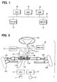
- FIG. 1 shows an electronic control system for use in an automotive vehicle.
- the system includes three commanding units, i.e., a commanding unit 31 for lane-keeping (referred to as CULK), a commanding unit 32 for automatically following a front vehicle (referred to as CUAF), and a commanding unit 33 for automatic parking (referred to as CUAP).
- the system also includes two driving units, i.e., a driving unit 13 for driving an assisting motor (referred to as EPS-ECU, or Electronic Control Unit for Electric Power Steering), and a driving unit 22 for changing a steering gear ratio (referred to as VGRS-ECU, or Electronic Control Unit for Variable Gear Ratio Steering) .
- the commanding units 31, 32, 33 and the driving units 13, 22 are all connected to a common communication bus 41 so that these units are communicable with one another.
- a front-watching camera 11 (shown in FIG. 3) is connected to the CULK 31, and the CULK 31 performs calculation necessary for keeping a present lane on which the vehicle is driving based on image information sent from the front-watching camera 11. Results of the calculation are transmitted to the EPS-ECU 13 or the VGRS-ECU 22 as a command value.
- a front watching radar 12 (shown in FIG. 3) is connected to the CUAF 32, and the CUAF 32 performs calculation necessary for keeping a distance between a front vehicle and the own vehicle based on information sent from the front-watching radar 12. Results of the calculation are transmitted to the commanding units 13, 22 as a command value.
- the information sent from the front-watching radar 12 includes a present distance between two vehicles and a driving speed of the front vehicle.
- a rear-watching camera (not shown) is connected to the CUAP 33, and the CUAP 33 performs calculation necessary for parking the vehicle at an intended position based on image information sent from the rear-watching camera. Results of the calculation is transmitted to the driving units 13, 22 as a command value.
- the EPS-ECU 13 or the VGRS-ECU 22 controls steering operation based the command values sent from the commanding units 31, 32, 33 and sends back to the commanding units 31, 32, 33 data indicating present conditions of the controls.
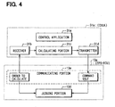
- FIG. 3 a motor-assisted power steering system and a steering gear ratio changing system are shown.
- the commanding unit 33 shown in FIG. 1 is not shown here though other commanding units 31, 32 are shown.
- a steering shaft 112a is connected to a steering wheel 110, and a pinion shaft 112b is connected to a pinion 112c.
- a steering angle sensor 211 is disposed between the steering shaft 112a and the pinion shaft 112b.
- a torque sensor 111 for detecting a steering torque is connected to the pinion shaft 112b.
- a pinion 112c is connected to the pinion shaft 112b and engages with a rack bar 118.
- a pair of vehicle wheels 124 to be steered are connected via knuckle arms 122.
- An EPS actuator 115(a power-assisting motor) is connected to the rack bar 118 via a pinion 115a.
- the EPS actuator 115 may be coaxially connected to the rack bar 118.
- the torque sensor 111 and the EPS actuator 115 are electrically connected to the EPS-ECU 13.
- the EPS-ECU 13 is a known type of an electronic control unit constituted by a microcomputer 13a (shown in FIG. 4) that includes a CPU, a RAM, a ROM and an I/O (an input/output interface).
- the EPS-ECU 13 calculates an amount of current to be supplied to the EPS actuator 115 under an EPS control program stored therein based on command values transmitted from the commanding units. More particularly, the amount of current to be supplied to the EPS actuator 115 is calculated based on a steering torque of the steering shaft 112a, which is detected by the torque sensor 111 .
- the EPS actuator 115 is driven to assist the steering torque of the steering shaft 112a.
- a steering angle sensor 211 and a VGRS actuator 212 are connected to the steering shaft 112a.
- the VGRS-ECU 22 is electrically connected to the steering angle sensor 211 and to the VGRS actuator 212.
- the VGRS-ECU 22 is a known type of an electronic control unit constituted by a microcomputer that includes a CPU, a RAM, a ROM and an I/O (an input/output interface).
- the VGRS-ECU 22 calculates a steering angle to be generated in the VGRS actuator 212 under a VGRS control program stored therein based on command values transmitted from the commanding units. More particularly, the amount of current to be supplied to the VGRS actuator 212 is calculated based on a steering angle detected by the steering angle sensor 211. The VGRS actuator 212 is driven to change a relative angle between the steering shaft 112a and the pinion shaft 112b.
- a process of detecting abnormality in the commanding units will be explained, taking as an example the motor-assisted power steering system including the driving unit EPS-ECU 13 and the commanding units 31, 32 and 33. Since an abnormality-detecting process in the steering gear ratio changing system is similar to that of the motor-assisted power steering system, it will not be explained here.
- the similar detecting process may be applied to other systems such as an anti-lock braking system, an anti-skid system or an active rear wheel steering system (4WS).
- FIG. 2 shows flows of information (including orders to calculate and command values) in the motor-assisted power steering system.
- An order to calculate a command value is transmitted from a microcomputer 13a in the driving unit EPS-ECU 13 to a microcomputer 31a in the commanding unit CULK 31, to a microcomputer 32b in the commanding unit CUAF 32, and to a microcomputer 33c in the commanding unit CUAP 33.
- Each microcomputer 31a, 32b, 33c calculates a command value in response to the order to calculate transmitted from the EPS-ECU 13 and sends back to the EPS-ECU 13 a result of calculation, i.e., a command value.
- the EPS-ECU 13 makes a judgment as to whether the command value is correct or not with reference to data stored therein. If the command value is not correct, it is determined that the commanding unit 31, 32 or 33 that has transmitted the incorrect command value is abnormal or malfunctioning. The correct command values are sent to a motor driver 13c, while a prohibiting device 13b prevents the incorrect command value from being supplied to the motor driver 13c.
- Order numbers and calculation parameters corresponding to the respective orders to calculate are stored in the driving unit EPS-ECU 13 to avoid traffic congestion in the communication bus 41 in the process of sending the orders to calculate.
- a calculation command corresponding to each order number sent form the driving unit EPS-ECU 31 is stored in each commanding unit 31, 32, 33.
- the EPS-ECU 13 detects abnormality in each commanding units 31, 32, 33 based on the command value transmitted from the commanding unit in response to the order to calculate.
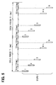
- FIG. 5 shows a timing chart of communication between the driving unit EPS-ECU 13 and the commanding units, i.e., CULK 31, CUAF 32 and CUAP 33.
- the order to calculate is transmitted from the EPS-ECU 13 to the CULK 31.
- the command value (results of calculation in response the order to calculate) is transmitted from the CULK 31 to the EPS-ECU 13, and the EPS-ECU 13 determines whether the command value is correct to thereby detect abnormality in the CULK 31.
- the EPS-ECU 13 transmits the order to calculate to the CUAF 32.
- the command value is transmitted from the CUAF 32 to the EPS-ECU 13, and the EPS-ECU 13 determines whether the command value is correct to thereby detect abnormality in the CUAF 32.
- the EPS-ECU 13 transmits the order to calculate to the CUAP 33.
- the command value is transmitted from the CUAP 33 to the EPS-ECU 13, and the EPS-ECU 13 determines whether the command value is correct to thereby detect abnormality in the CUAP 33.
- the EPS-ECU 13 transmits the order to calculate to the CULK 31.
- Each step is performed in a period of T2 millisecond (ms), and one cycle from step 1 to step N is performed in a period of T1 millisecond (ms). Since the communication between the driving unit EPS-ECU 13 and the commanding units 31, 32, 33 are performed in a time-sharing manner as explained above, congestion in the communication bus 41 is surely avoided.
- the communication between the driving unit 13 and the commanding units 31, 32, 33 is performed in a cyclic manner as explained above. It is also possible to change the order or the number of times for performing the communication between the driving unit 13 and the respective commanding units 31, 32, 33 according to driving conditions of the vehicle, such as a vehicle speed or an amount of a steering angle.
- the number of steps N in one cycle time T1 (ms) may be changed, or the order to calculate may be sent to the commanding unit CULK 31 at each odd numbered step and to the commanding units CUAF 32 and CUAP 33 at each even numbered step.
- the cycle period T1 (ms) has to be set so that the driving unit EPS-ECU 13 is not driven by an abnormal command value sent from the commanding units 31 32, 33.
- the command value sent from the commanding unit CULK 31 has to be checked before the EPS actuator 115 is driven by that command value.
- the microcomputer 31a in the commanding unit CULK 31 includes a receiver 31b, a calculating portion 31c, a transmitter 31d and a control application 31e installed therein.
- the microcomputer 13a in the driving unit EPS-ECU 13 includes a judging portion 13d and a communicating portion 13e.
- the order to calculate is sent from the communicating portion 13e to the receiver 31b and to the judging portion 13d, and the calculating portion 31c calculates the command value in response to the order to calculate.
- the transmitter 31d sends out the command value to the communicating portion 13e, and the judging portion 13d of the microcomputer 13a determines whether the command value is correct or not.
- step S1 upon starting operation of the EPS-ECU 13, the EPS-ECU 13 is initialized.
- step S2 an initializing signal is sent to the communication bus 41, and commanding units 31, 32, 33 responding to the initializing signal are recognized.
- abnormality in the commanding unit CULK 31 is detected at the next steps S3-S6.
- step S3 an order to calculate a command value is sent from the driving unit EPS-ECU 13 to the commanding unit CULK 31.
- step S4 the CULK 31 calculates the command value in response to the order to calculate and sends back the command value to the EPS-ECU 13.
- the EPS-ECU 13 receives the command value at step S4 and judges whether the command value is correct at step S5. If the command value is correct, the process directly proceeds to step S7. If not, the process proceeds to step S7 after setting a flag showing abnormality in the commanding unit CULK 31 at step S6.
- step S7 and step S8 Abnormality in the commanding unit CUAF 32 and the commanding unit CUAP 33 is detected at step S7 and step S8, respectively, in the same manner as done in the steps S3-S6 for the commanding unit CULK 31. Then, the process proceeds to step S9. At step S9, it is determined whether abnormality is involved in any one of the commanding units 31, 32, 33. If no abnormality is detected in all of the commanding units 31, 32, 33, the process proceeds to step S10, where the EPS actuator 115 is normally driven according to the command values sent from the commanding units 31, 32, 33.
- step S11 If abnormality is detected in any one of the commanding units 31, 32, 33, the process proceeds to step S11, where the EPS actuator 115 is driven without using the command value sent from the commanding unit involving the abnormality. If the command values sent from all of the commanding units 31, 32, 33 are not correct, the EPS-ECU 13 drives the EPS actuator 115 according to a steering torque detected by the independent torque sensor 111.
Description
- The present invention relates to an automotive electronic control system that includes a commanding unit and a driving unit, both communicably connected to each other, and more particularly to such a system having a capability of detecting abnormality or malfunction in the commanding unit.
- An example of a so-called Lan-Pulse system for detecting abnormality or malfunction in an electronic control unit is disclosed in JP-B2-58-55535. This system includes: a microcomputer for outputting signals for controlling loads, a watchdog circuit for detecting abnormality in the microcomputer and for outputting a reset signal; a fail-safe circuit for outputting a fail-safe signal in response to the reset signal; and a switching circuit for switching control signals of the microcomputer to a fail-safe side in response to the fail-safe signal. A signal synchronized with a machine cycle of the microcomputer, when a computer program is executed, is generated. It is determined that abnormality is involved in the microcomputer if the synchronized signal is not generated.
- In the so-called Lan-Pulse system, however, there is a possibility that abnormality of the calculating function in the microcomputer may not be detected although an excursion of the microcomputer is usually found. If the computing malfunction or abnormality is not detected, actuators may be driven using the abnormally calculated value. To solve this problem, a method for detecting such abnormality with a plurality of microcomputers has been proposed. This method, however, makes the system expensive.
- Further, if the Lan-Pulse system is used in a network in which plural electronic control units cooperate with one another, the Lan-Pulse has to be continuously outputted. Therefore, traffic in a communication bus is congested, and data may collide with one another and communication speed may be decreased. Accordingly, it is difficult to transmit the Lan-Pulse through the common bus, and a communication line exclusive for the Lan-Pulse has to be provided. This makes the system expensive.
- Document WO 98/36956 describes a brake system for a motor vehicle, which includes a pedal unit by which movements of the motor vehicle brake pedal are detected by means of at least one sensor and desired values are generated which correspond to the brake application force desired by the driver. Furthermore, electrically activated brake actuators assigned to the wheels of the motor vehicle are provided. A central control unit, which evaluates the sensor signals, generates control signals for additional brake functions. Through a data bus connecting the pedal unit, brake actuators and central control unit, data blocks are exchanged in accordance with a predefined, cyclic time frame. The pedal unit is also connected with the central control unit and the brake actuators over an additional signal line which enables a redundant transmission of control signals and data.
- According to the features of the preambles of
claims - The present invention has been made in view of the above-mentioned problem, and an object of the present invention is to provide an improved electronic control system including plural microcomputers in a network, in which abnormality or malfunction of the microcomputers is surly detected without increasing a cost of the system.
- The object is solved by the features of the independent claims. The dependent claims are directed to preferred embodiments of the invention.
- The abnormality detection may be performed periodically at a predetermined interval. In a system where plural commanding units are connected, the abnormality detection in each commanding unit may be performed in a time-sharing method. The order and the interval of sending the order to calculate to plural commanding units may be variously set according to operating conditions of the driving unit in order to obtain the command value timely from each commanding unit. The detection of the abnormality in the commanding unit is performed before the actuator is driven to avoid the actuator from being driven based on an incorrect command value. When one command value is found to be incorrect, the actuator may be driven based on other correct command values without using the incorrect command value. The electronic control system according to the present invention is advantageously applicable to a motor-assisted power steering system. In this system, the driving unit is an electronic control unit for driving an electric motor assisting a steering torque.
- According to the present invention, the abnormality or malfunction in the commanding unit is surely detected without using any additional communication line or device for detecting the abnormality. The electronic control system, therefore, can be manufactured at a low cost. Other objects and features of the present invention will become more readily apparent from a better understanding of the preferred embodiment described below with reference to the following drawings.
-
- FIG. 1 is a block diagram showing an entire structure of an electronic control system;
- FIG. 2 is a block diagram showing flows of commands and orders in the electronic control system;
- FIG. 3 is a schematic diagram showing an electric-power-assisted steering system mounted on an automotive vehicle, as an example of the electronic control system of the present invention;
- FIG. 4 is a block diagram showing a signal flow between a microcomputer in a commanding unit for lane-keeping and a microcomputer in a driving unit for driving an assisting motor;
- FIG. 5 is a timing chart showing timing of transmitting an order to calculate from a driving unit and timing of receiving a command value from a commanding unit; and
- FIG. 6 is a flowchart showing a process of detecting abnormality in a commanding unit.
- A preferred embodiment of the present invention will be described with reference to accompanying drawings. FIG. 1 shows an electronic control system for use in an automotive vehicle. The system includes three commanding units, i.e., a
commanding unit 31 for lane-keeping (referred to as CULK), acommanding unit 32 for automatically following a front vehicle (referred to as CUAF), and acommanding unit 33 for automatic parking (referred to as CUAP). The system also includes two driving units, i.e., adriving unit 13 for driving an assisting motor (referred to as EPS-ECU, or Electronic Control Unit for Electric Power Steering), and adriving unit 22 for changing a steering gear ratio (referred to as VGRS-ECU, or Electronic Control Unit for Variable Gear Ratio Steering) . Thecommanding units driving units common communication bus 41 so that these units are communicable with one another. - A front-watching camera 11 (shown in FIG. 3) is connected to the CULK 31, and the CULK 31 performs calculation necessary for keeping a present lane on which the vehicle is driving based on image information sent from the front-watching
camera 11. Results of the calculation are transmitted to the EPS-ECU 13 or the VGRS-ECU 22 as a command value. A front watching radar 12 (shown in FIG. 3) is connected to the CUAF 32, and the CUAF 32 performs calculation necessary for keeping a distance between a front vehicle and the own vehicle based on information sent from the front-watching radar 12. Results of the calculation are transmitted to thecommanding units radar 12 includes a present distance between two vehicles and a driving speed of the front vehicle. - Similarly, a rear-watching camera (not shown) is connected to the CUAP 33, and the CUAP 33 performs calculation necessary for parking the vehicle at an intended position based on image information sent from the rear-watching camera. Results of the calculation is transmitted to the
driving units commanding units commanding units - In FIG. 3, a motor-assisted power steering system and a steering gear ratio changing system are shown. The
commanding unit 33 shown in FIG. 1 is not shown here though othercommanding units steering shaft 112a is connected to asteering wheel 110, and apinion shaft 112b is connected to apinion 112c. Asteering angle sensor 211 is disposed between the steeringshaft 112a and thepinion shaft 112b. Atorque sensor 111 for detecting a steering torque is connected to thepinion shaft 112b. Apinion 112c is connected to thepinion shaft 112b and engages with arack bar 118. At both ends of therack bar 118, a pair ofvehicle wheels 124 to be steered are connected viaknuckle arms 122. An EPS actuator 115(a power-assisting motor) is connected to therack bar 118 via apinion 115a. Alternatively, theEPS actuator 115 may be coaxially connected to therack bar 118. - The
torque sensor 111 and theEPS actuator 115 are electrically connected to the EPS-ECU 13. The EPS-ECU 13 is a known type of an electronic control unit constituted by amicrocomputer 13a (shown in FIG. 4) that includes a CPU, a RAM, a ROM and an I/O (an input/output interface). The EPS-ECU 13 calculates an amount of current to be supplied to theEPS actuator 115 under an EPS control program stored therein based on command values transmitted from the commanding units. More particularly, the amount of current to be supplied to theEPS actuator 115 is calculated based on a steering torque of thesteering shaft 112a, which is detected by thetorque sensor 111 . TheEPS actuator 115 is driven to assist the steering torque of thesteering shaft 112a. - Now, the steering gear ratio changing system will be explained. A
steering angle sensor 211 and aVGRS actuator 212 are connected to thesteering shaft 112a. The VGRS-ECU 22 is electrically connected to thesteering angle sensor 211 and to theVGRS actuator 212. The VGRS-ECU 22 is a known type of an electronic control unit constituted by a microcomputer that includes a CPU, a RAM, a ROM and an I/O (an input/output interface). - The VGRS-
ECU 22 calculates a steering angle to be generated in theVGRS actuator 212 under a VGRS control program stored therein based on command values transmitted from the commanding units. More particularly, the amount of current to be supplied to theVGRS actuator 212 is calculated based on a steering angle detected by thesteering angle sensor 211. The VGRS actuator 212 is driven to change a relative angle between the steeringshaft 112a and thepinion shaft 112b. - A process of detecting abnormality in the commanding units will be explained, taking as an example the motor-assisted power steering system including the driving unit EPS-
ECU 13 and thecommanding units - FIG. 2 shows flows of information (including orders to calculate and command values) in the motor-assisted power steering system. An order to calculate a command value is transmitted from a
microcomputer 13a in the driving unit EPS-ECU 13 to amicrocomputer 31a in thecommanding unit CULK 31, to amicrocomputer 32b in thecommanding unit CUAF 32, and to amicrocomputer 33c in thecommanding unit CUAP 33. Eachmicrocomputer ECU 13 and sends back to the EPS-ECU 13 a result of calculation, i.e., a command value. The EPS-ECU 13 makes a judgment as to whether the command value is correct or not with reference to data stored therein. If the command value is not correct, it is determined that thecommanding unit motor driver 13c, while a prohibitingdevice 13b prevents the incorrect command value from being supplied to themotor driver 13c. - Order numbers and calculation parameters corresponding to the respective orders to calculate are stored in the driving unit EPS-
ECU 13 to avoid traffic congestion in thecommunication bus 41 in the process of sending the orders to calculate. On the other hand, a calculation command corresponding to each order number sent form the driving unit EPS-ECU 31 is stored in eachcommanding unit ECU 13 detects abnormality in eachcommanding units - FIG. 5 shows a timing chart of communication between the driving unit EPS-
ECU 13 and the commanding units, i.e.,CULK 31,CUAF 32 andCUAP 33. Atstep 1, the order to calculate is transmitted from the EPS-ECU 13 to theCULK 31. Atstep 2, the command value (results of calculation in response the order to calculate) is transmitted from theCULK 31 to the EPS-ECU 13, and the EPS-ECU 13 determines whether the command value is correct to thereby detect abnormality in theCULK 31. At thesame step 2, the EPS-ECU 13 transmits the order to calculate to theCUAF 32. Atstep 3, the command value is transmitted from theCUAF 32 to the EPS-ECU 13, and the EPS-ECU 13 determines whether the command value is correct to thereby detect abnormality in theCUAF 32. At thesame step 3, the EPS-ECU 13 transmits the order to calculate to theCUAP 33. At the next step 4 (not shown in FIG. 5), the command value is transmitted from theCUAP 33 to the EPS-ECU 13, and the EPS-ECU 13 determines whether the command value is correct to thereby detect abnormality in theCUAP 33. At the same step 4, the EPS-ECU 13 transmits the order to calculate to theCULK 31. These steps are repeated up to the last step N. At the last step N, however, the command value is received from theCUAP 33 but the order to calculate is not transmitted to theCULK 31. - Each step is performed in a period of T2 millisecond (ms), and one cycle from
step 1 to step N is performed in a period of T1 millisecond (ms). Since the communication between the driving unit EPS-ECU 13 and thecommanding units communication bus 41 is surely avoided. The communication between the drivingunit 13 and thecommanding units unit 13 and the respectivecommanding units commanding unit CULK 31 at each odd numbered step and to the commanding units CUAF 32 andCUAP 33 at each even numbered step. The cycle period T1 (ms) has to be set so that the driving unit EPS-ECU 13 is not driven by an abnormal command value sent from thecommanding units 31 32, 33. The command value sent from thecommanding unit CULK 31 has to be checked before theEPS actuator 115 is driven by that command value. - A process of detecting abnormality in the commanding units will be further explained with reference to FIG. 4 showing communication flows in the system and FIG. 6 showing a process flowchart. As shown in FIG. 4, the
microcomputer 31a in thecommanding unit CULK 31 includes areceiver 31b, a calculatingportion 31c, atransmitter 31d and acontrol application 31e installed therein. Themicrocomputer 13a in the driving unit EPS-ECU 13 includes a judgingportion 13d and a communicatingportion 13e. The order to calculate is sent from the communicatingportion 13e to thereceiver 31b and to the judgingportion 13d, and the calculatingportion 31c calculates the command value in response to the order to calculate. Thetransmitter 31d sends out the command value to the communicatingportion 13e, and the judgingportion 13d of themicrocomputer 13a determines whether the command value is correct or not. - Now, referring to FIG. 6, the process of detecting abnormality in the commanding units will be explained. At step S1, upon starting operation of the EPS-
ECU 13, the EPS-ECU 13 is initialized. At step S2, an initializing signal is sent to thecommunication bus 41, andcommanding units commanding unit CULK 31 is detected at the next steps S3-S6. At step S3, an order to calculate a command value is sent from the driving unit EPS-ECU 13 to thecommanding unit CULK 31. At step S4, theCULK 31 calculates the command value in response to the order to calculate and sends back the command value to the EPS-ECU 13. The EPS-ECU 13 receives the command value at step S4 and judges whether the command value is correct at step S5. If the command value is correct, the process directly proceeds to step S7. If not, the process proceeds to step S7 after setting a flag showing abnormality in thecommanding unit CULK 31 at step S6. - Abnormality in the
commanding unit CUAF 32 and thecommanding unit CUAP 33 is detected at step S7 and step S8, respectively, in the same manner as done in the steps S3-S6 for thecommanding unit CULK 31. Then, the process proceeds to step S9. At step S9, it is determined whether abnormality is involved in any one of thecommanding units commanding units EPS actuator 115 is normally driven according to the command values sent from thecommanding units commanding units EPS actuator 115 is driven without using the command value sent from the commanding unit involving the abnormality. If the command values sent from all of thecommanding units ECU 13 drives theEPS actuator 115 according to a steering torque detected by theindependent torque sensor 111.
Claims (6)
- An electronic control system for use in an automobile vehicle, comprisinga driving unit (13, 22) for driving an actuator (115, 212), which includes a first microcomputer (13a), anda command value calculation unit (31, 32, 33), which includes a second microcomputer (31a, 32b, 33c), for calculating a first command value and a second command value, characterized by further comprising :the driving unit (13, 22) is adapted to transmit an order to calculate the first command value to the command value calculation unit (31, 32, 33) for detecting abnormality of the command value calculation unit (31, 32, 33);the command value calculation unit (31, 32, 33) is adapted to calculate the first command value by the second microcomputer (31a, 32b, 33c) in response to the order from the driving unit (13, 22) and to calculate the second command value by the second microcomputer (31a, 32b, 33c) based on sensing information supplied to the command value calculation unit (31, 32, 33), and to transmit the first and second command value to the driving unit (13, 22), andthe driving unit (13, 22) is adapted to detect the abnormality in the command value calculation unit (31, 32, 33) by the first microcomputer (13a) based on the first command value transmitted from the command value calculation unit (31, 32, 33), and to drive the actuator (115, 212) based on the second command value, when no abnormality in the command value calculation unit (31, 32, 33) is detected.
- The electronic control system as in claim 1, wherein the abnormality in the command value calculation unit (31, 32, 33) is periodically detected at a predetermined interval.
- The electronic control system as in claim 1 or 2, whereinthe abnormality in the command value calculation unit (31, 32, 33) is detected based on the first command value before the driving unit (13, 22) drives the actuator (115, 212) according to the second command value.
- The electronic control system as in any one of claims 1-3, whereinwhen the driving unit (13, 22) transmits the order to calculate to a plurality of the command value calculation units (31, 32, 33), an order and an interval of the transmission are set according to operating conditions of the driving unit (13, 22).
- The electronic control system as in any one of claims 1-4, whereinthe driving unit (13, 22) is an electric power steering unit (13) for driving an electric motor (115) that assists a steering torque of a driver and a variable gear ratio steering unit (22) for driving an electric motor (212) that changes a relative angle between a. steering wheel and vehicle wheels.
- An electronic control method for use in an automobile vehicle, characterized by the steps oftransmitting an order to calculate a first command value from a driving unit (13, 22) for driving an actuator (115, 212) to a command value calculation unit (31, 32, 33), wherein said first command value is for detecting an abnormality of the command value calculation unit (31, 32, 33),calculating the first command value by a second microcomputer (31a, 32b, 33c) included in the command value calculation unit (31, 32, 33) in response to the order, and calculating a second command value based on sensing information supplied to the command value calculation unit (31, 32, 33),transmitting the first and second command value from the command calculation unit (31, 32, 33) to the driving unit (13, 22),detecting an abnormality in the command value calculation unit (31, 32, 33) by a first microcomputer (13a) included in the driving unit (13, 22), based on the first command value transmitted from the command value calculation unit (31, 32, 33), anddriving the actuator (115, 212) based on the second command value by the driving unit (13, 22), when no abnormality in the calculated command value calculation unit (31, 32, 33) is detected.
Applications Claiming Priority (2)
| Application Number | Priority Date | Filing Date | Title |
|---|---|---|---|
| JP2004070991A JP4379793B2 (en) | 2004-03-12 | 2004-03-12 | Electronic control device for vehicle |
| JP2004070991 | 2004-03-12 |
Publications (3)
| Publication Number | Publication Date |
|---|---|
| EP1574419A2 EP1574419A2 (en) | 2005-09-14 |
| EP1574419A3 EP1574419A3 (en) | 2005-11-16 |
| EP1574419B1 true EP1574419B1 (en) | 2007-05-09 |
Family
ID=34824634
Family Applications (1)
| Application Number | Title | Priority Date | Filing Date |
|---|---|---|---|
| EP05003340A Expired - Fee Related EP1574419B1 (en) | 2004-03-12 | 2005-02-16 | Automotive electronic control system including communicably connected commanding unit and driving unit |
Country Status (4)
| Country | Link |
|---|---|
| US (1) | US7421302B2 (en) |
| EP (1) | EP1574419B1 (en) |
| JP (1) | JP4379793B2 (en) |
| DE (1) | DE602005001061T2 (en) |
Families Citing this family (20)
| Publication number | Priority date | Publication date | Assignee | Title |
|---|---|---|---|---|
| DE10313409A1 (en) * | 2003-03-25 | 2004-11-18 | Continental Teves Ag & Co. Ohg | Method for avoiding incorrect actuator access in a multifunctional electronic overall control system |
| JP2006259935A (en) * | 2005-03-15 | 2006-09-28 | Denso Corp | Computation device with computation abnormality determination function |
| WO2007112603A1 (en) * | 2006-04-03 | 2007-10-11 | Thyssenkrupp Presta Ag | Monitoring device for the function of an electronic control device, and method for this purpose |
| JP4408921B2 (en) | 2007-08-22 | 2010-02-03 | 株式会社デンソー | Electronics |
| US8028789B2 (en) * | 2008-07-31 | 2011-10-04 | GM Global Technology Operations LLC | Control adaptation of variable gear ratio steering |
| KR101246403B1 (en) * | 2009-10-15 | 2013-03-21 | 주식회사 만도 | Method and system for detecting decelerator trouble |
| US8626392B2 (en) * | 2010-06-23 | 2014-01-07 | Toyota Jidosha Kabushiki Kaisha | Vehicle running control apparatus |
| DE102010030646A1 (en) * | 2010-06-29 | 2011-12-29 | Zf Lenksysteme Gmbh | Guide assistance tracking method for motor car, involves calculating change of transmission ratio between steering wheel angle and wheel steering angle of two steerable wheels of car by overlay unit of steering system |
| JP5477654B2 (en) * | 2010-10-22 | 2014-04-23 | 株式会社デンソー | Electronic control device and electric power steering device using the same |
| JP5672966B2 (en) | 2010-10-29 | 2015-02-18 | 株式会社デンソー | Vehicle motion control system |
| JP5672968B2 (en) | 2010-10-29 | 2015-02-18 | 株式会社デンソー | Vehicle motion control device and vehicle motion control system having the same |
| US9014916B2 (en) | 2010-10-29 | 2015-04-21 | Denso Corporation | Vehicle dynamic control apparatus and vehicle dynamic control system using the same |
| JP2013095379A (en) * | 2011-11-04 | 2013-05-20 | Denso Corp | Vehicle behavior control device |
| DE102015201032B4 (en) * | 2015-01-22 | 2018-12-20 | Volkswagen Aktiengesellschaft | Steering system for automated driving of a motor vehicle |
| DE102015202326A1 (en) * | 2015-02-10 | 2016-08-11 | Robert Bosch Gmbh | Method for operating a data processing unit of a driver assistance system and data processing unit |
| JP6521468B2 (en) * | 2017-06-15 | 2019-05-29 | 株式会社Subaru | Automatic steering control device |
| CN112148020B (en) * | 2020-09-10 | 2021-06-25 | 无锡卡尔曼导航技术有限公司 | EPS-based agricultural machinery automatic driving system and control method |
| JP2022107380A (en) | 2021-01-08 | 2022-07-21 | 株式会社デンソー | Load drive system |
| JP7109621B1 (en) * | 2021-05-06 | 2022-07-29 | 三菱電機株式会社 | control system |
| JP2023111386A (en) | 2022-01-31 | 2023-08-10 | 株式会社アドヴィックス | Vehicle momentum control device and momentum control program |
Family Cites Families (35)
| Publication number | Priority date | Publication date | Assignee | Title |
|---|---|---|---|---|
| JPS5855394B2 (en) | 1979-06-18 | 1983-12-09 | 日立造船株式会社 | Support structure for pipe group |
| JPS5855535B2 (en) | 1979-08-25 | 1983-12-10 | 日産自動車株式会社 | Multi-computer device for vehicles |
| JPS608159A (en) * | 1983-06-28 | 1985-01-17 | Jidosha Kiki Co Ltd | Power steering system control method |
| JP2528813B2 (en) * | 1985-05-10 | 1996-08-28 | 株式会社日立製作所 | Control device |
| JPH07115649B2 (en) * | 1985-05-24 | 1995-12-13 | 豊田工機株式会社 | Vehicle running condition determination device |
| US5053964A (en) * | 1989-07-17 | 1991-10-01 | Utdc, Inc. | On-board integrated vehicle control and communication system |
| GB2242716B (en) * | 1990-03-28 | 1994-04-06 | Nissan Motor | Control apparatus with fail-safe faculty |
| JPH04240997A (en) * | 1991-01-25 | 1992-08-28 | Fuji Heavy Ind Ltd | Control method for on-vehicle electronic device |
| DE4136338A1 (en) * | 1991-11-05 | 1993-05-06 | Robert Bosch Gmbh, 7000 Stuttgart, De | METHOD AND DEVICE FOR TROUBLESHOOTING IN ELECTRONIC CONTROL UNITS |
| JP2901849B2 (en) * | 1993-09-07 | 1999-06-07 | 三菱電機株式会社 | Fail detection device for anti-skid control device |
| JP3550728B2 (en) * | 1994-06-09 | 2004-08-04 | マツダ株式会社 | Vehicle integrated control device |
| JPH08132992A (en) * | 1994-11-10 | 1996-05-28 | Mitsubishi Electric Corp | On-vehicle controller |
| US5833325A (en) * | 1996-02-06 | 1998-11-10 | Westinghouse Air Brake Company | Freight brake control using train net braking ratio |
| JP3622329B2 (en) * | 1996-03-08 | 2005-02-23 | スズキ株式会社 | Vehicle steering device |
| DE19609242A1 (en) * | 1996-03-09 | 1997-09-11 | Bosch Gmbh Robert | Method and device for controlling a drive unit of a vehicle |
| DE19611944C2 (en) * | 1996-03-26 | 2003-03-27 | Daimler Chrysler Ag | Integrated circuit for coupling a micro-controlled control unit to a two-wire bus |
| JP3288390B2 (en) * | 1997-02-19 | 2002-06-04 | シーメンス アクチエンゲゼルシヤフト | Vehicle brake system and method for data transmission in electrically controlled vehicle brake system |
| DE19712375A1 (en) * | 1997-03-25 | 1998-10-01 | Bosch Gmbh Robert | Watchdog circuit |
| US5832418A (en) * | 1997-06-23 | 1998-11-03 | Micron Electronics | Apparatus for testing a controller with random contraints |
| US6275165B1 (en) * | 1998-03-19 | 2001-08-14 | Westinghouse Air Brake Company | A.A.R. compliant electronic braking system |
| JPH11272498A (en) * | 1998-03-25 | 1999-10-08 | Denso Corp | Electronic controller |
| DE19939567B4 (en) * | 1999-08-20 | 2007-07-19 | Pilz Gmbh & Co. Kg | Device for controlling safety-critical processes |
| US6550057B1 (en) * | 1999-08-31 | 2003-04-15 | Accenture Llp | Piecemeal retrieval in an information services patterns environment |
| US6792321B2 (en) * | 2000-03-02 | 2004-09-14 | Electro Standards Laboratories | Remote web-based control |
| US6496900B1 (en) * | 2000-09-12 | 2002-12-17 | 3Ware, Inc. | Disk array system, controller, and method for verifying command data written to disk drives |
| JP2002250250A (en) | 2001-02-22 | 2002-09-06 | Kokusan Denki Co Ltd | Internal combustion engine control device |
| CN1222138C (en) * | 2001-05-31 | 2005-10-05 | 欧姆龙株式会社 | Safety network system and safety slaves and safety controller and communication method and information gathering method and monitoring method in safety network system |
| JP2003069731A (en) * | 2001-08-29 | 2003-03-07 | Mitsubishi Electric Corp | Remote equipment state monitoring system |
| JP4061528B2 (en) * | 2001-12-27 | 2008-03-19 | 株式会社デンソー | Vehicle abnormality diagnosis device |
| JP3975823B2 (en) * | 2002-05-15 | 2007-09-12 | 株式会社ジェイテクト | Vehicle steering system |
| US6856877B2 (en) * | 2002-05-29 | 2005-02-15 | Ford Global Technologies, Llc | Integration of active assist and vehicle dynamics control and method |
| JP4052051B2 (en) * | 2002-07-26 | 2008-02-27 | ダイキン工業株式会社 | Fault diagnosis system and diagnostic server |
| JP2004110613A (en) * | 2002-09-20 | 2004-04-08 | Toshiba Corp | Controller, control program, objective device, and control system |
| JP2004259137A (en) * | 2003-02-27 | 2004-09-16 | Denso Corp | Electronic control device |
| US7197669B2 (en) * | 2003-07-30 | 2007-03-27 | Via Technologies, Inc. | Method and circuit for command integrity checking (CIC) in a graphics controller |
-
2004
- 2004-03-12 JP JP2004070991A patent/JP4379793B2/en not_active Expired - Fee Related
-
2005
- 2005-02-16 DE DE602005001061T patent/DE602005001061T2/en active Active
- 2005-02-16 EP EP05003340A patent/EP1574419B1/en not_active Expired - Fee Related
- 2005-03-11 US US11/078,959 patent/US7421302B2/en active Active
Also Published As
| Publication number | Publication date |
|---|---|
| JP4379793B2 (en) | 2009-12-09 |
| EP1574419A3 (en) | 2005-11-16 |
| US7421302B2 (en) | 2008-09-02 |
| DE602005001061T2 (en) | 2008-01-10 |
| DE602005001061D1 (en) | 2007-06-21 |
| JP2005255037A (en) | 2005-09-22 |
| EP1574419A2 (en) | 2005-09-14 |
| US20050203646A1 (en) | 2005-09-15 |
Similar Documents
| Publication | Publication Date | Title |
|---|---|---|
| EP1574419B1 (en) | Automotive electronic control system including communicably connected commanding unit and driving unit | |
| EP2467290B1 (en) | Fail safe operational steering system for autonomous driving | |
| EP2418142B1 (en) | Controller of vehicle | |
| CN109733461B (en) | Redundant electronic steering system and control method for autonomous vehicle | |
| EP1510436B1 (en) | Vehicle steering system | |
| EP2810853B1 (en) | Actuator control apparatus | |
| EP2495156B1 (en) | Device for controlling vehicle travel | |
| EP1803628B1 (en) | Vehicle control apparatus for quickly dealing with communication abnormality in communication means between calculation control devices | |
| EP1394014B1 (en) | Vehicle steering system | |
| US10875569B2 (en) | Steering arbitration apparatus and method of vehicle, and steering arbitration system having the same | |
| US20210129855A1 (en) | Electronic control device, control system, and reset determination method | |
| CN114026010B (en) | Steering control device and steering assist system including the same | |
| US20180029593A1 (en) | Driving control system for vehicle | |
| JP4164691B2 (en) | Integrated control device for vehicle | |
| JP6455082B2 (en) | In-vehicle device control system | |
| JP4382345B2 (en) | Vehicle steering system | |
| US20080119987A1 (en) | Steering angle detection by means of ESC and EPAS | |
| US11427254B2 (en) | Evasive steering assist with a pre-active phase | |
| EP3693249B1 (en) | Motor control device | |
| CN115246438A (en) | Method for operating a vehicle | |
| JP7270463B2 (en) | vehicle steering device | |
| KR100670189B1 (en) | Failsafe control method of seering system using afs system | |
| US20240101187A1 (en) | Steer-by-wire system capable of controlling steering in case of breakdown of steering feedback actuator and method of controlling steering in case of breakdown of steering feedback actuator | |
| CN114987600A (en) | Control method and device for keeping central position of automobile steering wheel and automobile | |
| JP2022081019A (en) | Vehicle control system |
Legal Events
| Date | Code | Title | Description |
|---|---|---|---|
| PUAI | Public reference made under article 153(3) epc to a published international application that has entered the european phase |
Free format text: ORIGINAL CODE: 0009012 |
|
| AK | Designated contracting states |
Kind code of ref document: A2 Designated state(s): AT BE BG CH CY CZ DE DK EE ES FI FR GB GR HU IE IS IT LI LT LU MC NL PL PT RO SE SI SK TR |
|
| AX | Request for extension of the european patent |
Extension state: AL BA HR LV MK YU |
|
| PUAL | Search report despatched |
Free format text: ORIGINAL CODE: 0009013 |
|
| AK | Designated contracting states |
Kind code of ref document: A3 Designated state(s): AT BE BG CH CY CZ DE DK EE ES FI FR GB GR HU IE IS IT LI LT LU MC NL PL PT RO SE SI SK TR |
|
| AX | Request for extension of the european patent |
Extension state: AL BA HR LV MK YU |
|
| 17P | Request for examination filed |
Effective date: 20051219 |
|
| AKX | Designation fees paid |
Designated state(s): DE FR IT |
|
| GRAP | Despatch of communication of intention to grant a patent |
Free format text: ORIGINAL CODE: EPIDOSNIGR1 |
|
| RIC1 | Information provided on ipc code assigned before grant |
Ipc: B62D 6/00 20060101AFI20061010BHEP |
|
| GRAS | Grant fee paid |
Free format text: ORIGINAL CODE: EPIDOSNIGR3 |
|
| GRAA | (expected) grant |
Free format text: ORIGINAL CODE: 0009210 |
|
| AK | Designated contracting states |
Kind code of ref document: B1 Designated state(s): DE FR IT |
|
| REF | Corresponds to: |
Ref document number: 602005001061 Country of ref document: DE Date of ref document: 20070621 Kind code of ref document: P |
|
| ET | Fr: translation filed | ||
| PLBE | No opposition filed within time limit |
Free format text: ORIGINAL CODE: 0009261 |
|
| STAA | Information on the status of an ep patent application or granted ep patent |
Free format text: STATUS: NO OPPOSITION FILED WITHIN TIME LIMIT |
|
| 26N | No opposition filed |
Effective date: 20080212 |
|
| PG25 | Lapsed in a contracting state [announced via postgrant information from national office to epo] |
Ref country code: IT Free format text: LAPSE BECAUSE OF NON-PAYMENT OF DUE FEES Effective date: 20100216 |
|
| REG | Reference to a national code |
Ref country code: FR Ref legal event code: PLFP Year of fee payment: 11 |
|
| PGRI | Patent reinstated in contracting state [announced from national office to epo] |
Ref country code: IT Effective date: 20141217 |
|
| REG | Reference to a national code |
Ref country code: FR Ref legal event code: PLFP Year of fee payment: 12 |
|
| REG | Reference to a national code |
Ref country code: FR Ref legal event code: PLFP Year of fee payment: 13 |
|
| REG | Reference to a national code |
Ref country code: FR Ref legal event code: PLFP Year of fee payment: 14 |
|
| PGFP | Annual fee paid to national office [announced via postgrant information from national office to epo] |
Ref country code: IT Payment date: 20200225 Year of fee payment: 16 |
|
| PGFP | Annual fee paid to national office [announced via postgrant information from national office to epo] |
Ref country code: FR Payment date: 20200219 Year of fee payment: 16 |
|
| PG25 | Lapsed in a contracting state [announced via postgrant information from national office to epo] |
Ref country code: FR Free format text: LAPSE BECAUSE OF NON-PAYMENT OF DUE FEES Effective date: 20210228 |
|
| PGFP | Annual fee paid to national office [announced via postgrant information from national office to epo] |
Ref country code: DE Payment date: 20220217 Year of fee payment: 18 |
|
| PG25 | Lapsed in a contracting state [announced via postgrant information from national office to epo] |
Ref country code: IT Free format text: LAPSE BECAUSE OF NON-PAYMENT OF DUE FEES Effective date: 20210228 |
|
| REG | Reference to a national code |
Ref country code: DE Ref legal event code: R119 Ref document number: 602005001061 Country of ref document: DE |
|
| PG25 | Lapsed in a contracting state [announced via postgrant information from national office to epo] |
Ref country code: DE Free format text: LAPSE BECAUSE OF NON-PAYMENT OF DUE FEES Effective date: 20230901 |