EP1575686B1 - Frictional joint for toys - Google Patents
Frictional joint for toys Download PDFInfo
- Publication number
- EP1575686B1 EP1575686B1 EP03789759A EP03789759A EP1575686B1 EP 1575686 B1 EP1575686 B1 EP 1575686B1 EP 03789759 A EP03789759 A EP 03789759A EP 03789759 A EP03789759 A EP 03789759A EP 1575686 B1 EP1575686 B1 EP 1575686B1
- Authority
- EP
- European Patent Office
- Prior art keywords
- joint
- operative surface
- plug portion
- socket
- plug
- Prior art date
- Legal status (The legal status is an assumption and is not a legal conclusion. Google has not performed a legal analysis and makes no representation as to the accuracy of the status listed.)
- Expired - Lifetime
Links
- 210000004197 pelvis Anatomy 0.000 description 25
- 210000001624 hip Anatomy 0.000 description 3
- 230000013011 mating Effects 0.000 description 3
- 230000002401 inhibitory effect Effects 0.000 description 2
- 230000007246 mechanism Effects 0.000 description 2
- 230000000295 complement effect Effects 0.000 description 1
- 210000002310 elbow joint Anatomy 0.000 description 1
- 210000004394 hip joint Anatomy 0.000 description 1
- 238000010348 incorporation Methods 0.000 description 1
- 210000000629 knee joint Anatomy 0.000 description 1
- 238000004519 manufacturing process Methods 0.000 description 1
- 238000000034 method Methods 0.000 description 1
- 210000000323 shoulder joint Anatomy 0.000 description 1
Images
Classifications
-
- A—HUMAN NECESSITIES
- A63—SPORTS; GAMES; AMUSEMENTS
- A63H—TOYS, e.g. TOPS, DOLLS, HOOPS OR BUILDING BLOCKS
- A63H3/00—Dolls
- A63H3/36—Details; Accessories
- A63H3/46—Connections for limbs
-
- Y—GENERAL TAGGING OF NEW TECHNOLOGICAL DEVELOPMENTS; GENERAL TAGGING OF CROSS-SECTIONAL TECHNOLOGIES SPANNING OVER SEVERAL SECTIONS OF THE IPC; TECHNICAL SUBJECTS COVERED BY FORMER USPC CROSS-REFERENCE ART COLLECTIONS [XRACs] AND DIGESTS
- Y10—TECHNICAL SUBJECTS COVERED BY FORMER USPC
- Y10T—TECHNICAL SUBJECTS COVERED BY FORMER US CLASSIFICATION
- Y10T403/00—Joints and connections
- Y10T403/32—Articulated members
- Y10T403/32606—Pivoted
- Y10T403/32631—Universal ball and socket
- Y10T403/32681—Composite ball
- Y10T403/32704—Stud extends into ball
Definitions
- the present disclosure relates generally to movable toys, and more specifically, to joints of action figures and dolls.
- Movable action figures and dolls e.g., action figures having shoulder/elbow joints, hip/knee joints, waist joints, etc.
- Movable joint motion allows a child to configure a toy as he or she chooses. Examples of such toys are disclosed in U.S. Patent Nos. 3,277,602 ; 3,628,282 ; 3,988,855 ; 4,274,224 ; 4,968,282 ; 5,989,658 ; and 6,435,938 , the disclosures of which are incorporated herein by reference.
- joints and other structures which enable relative movement be durable, enable the desired range of movement, and be relatively inexpensive to manufacture.
- joints for dolls or puppet bodies are known. Each of these joints has a plug portion and a socket portion adapted to receive the plug portion.
- the plug portion may have protuberances in order to offer frictional resistance with an inner surface of the socket portion.
- the present invention is directed to a joint for a toy having the features of claim 1.
- the toy may be a doll or action figure, having the joint or like mechanism that enables relative movement.
- the toy includes two or more body part members interconnected by the joint having a plug and a socket for receiving the plug.
- the socket includes one or more protrusions, against which the plug is urged to create friction between the plug and socket, thereby restricting joint motion.
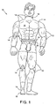
- Fig. 1 depicts an embodiment of a movable toy according to the present description.
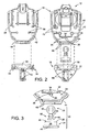
- Fig. 2 is a cross-sectional exploded view of the movable toy of Fig. 1 , showing components of the toy that are movably interconnected by a joint according to the present description.
- Fig. 3 is a detailed exploded view of the joint shown in Fig. 2 .
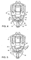
- Fig. 4 is a cross-sectional view of the components of Fig. 2 assembled.
- Fig. 5 is a cross-sectional view similar to Fig. 4 , but showing an alternate embodiment of a joint according to the present description.
- Fig. 1 depicts a toy 10 according to the present description.
- toy 10 is implemented as an action figure having several body part members 12 with movable interconnections between the members. These movable interconnections take the form of joints 14 defined between body part members 12. The joints enable the various body part members to be moved relative to one another in various ways.
- a given joint is configured to enable one part of the toy (e.g., a body part member) to be moved relative to another, and then maintain the relative position of the parts once a desired position has been achieved.
- toy 10 has a first body part member, such as torso 16, and a second body part member, such as pelvis 18.
- One of joints 14 forms a waist joint 20, defined between torso 16 and pelvis 18 to enable relative motion between the torso and pelvis.
- the remaining description will focus primarily on the waist joint, though it should be appreciated that the structures and mechanisms to be discussed may be implemented in other locations on a doll, and in movable toys other than dolls.
- joint 20 may include a plug portion or assembly 22, and a socket portion or assembly 24 that receives plug 22.
- Plug portion 22 is formed on one of the first and second body part members, such as on pelvis 18, while socket portion 24 is formed on the other of the first and second body part members, such as on torso 16.
- Socket portion 24 includes a friction assembly 26 that inhibits relative movement between plug portion 22 and socket portion 24. Friction is produced between multiple socket contact regions 28 and plug contact regions 30, also referred to as the operative surface of plug portion 22. In the depicted examples, contact regions take the shape of a sphere, though it should be appreciated that other shapes and configurations may be employed.
- socket portion 24 has a support surface or wall portion 32 with several protrusions 34 extending therefrom that form socket contact regions 28.
- Joint 14 may be adapted so that plug portion 22 is urged into contact with protrusions 34 so as to create friction therebetween. The body part members are therefore able to maintain their relative positions during play.
- joint 14 is comprised of socket portion 24 and plug portion 22. These portions engage with one another to control relative movement between torso 16 and pelvis 18 (e.g., by inhibiting relative movement through friction), or other appropriate body part members 12.
- Plug contact region 30 articulates within socket portion 24. In some embodiments, plug contact region 30 is spherical and mates with a cylindrically shaped socket portion, as shown in Figs. 2-4 . Alternatively, only part of plug portion 22 may be convex and used as a contact region.
- socket portion 24 includes a socket insert 36.
- This insert may be useful in retaining plug portion 22 captured and held within socket portion 24 and increasing the frictional surface contact between socket portion 24 and plug portion 22.
- socket insert 36 is replaced by additional protrusions 34, or extension of the existing lateral protrusions, thus reducing the number of overall components needed to assemble toy 10.
- insert 36 has an opening sized to accommodate passage of a shaft 58 that extends away from operative surface 30 of plug portion 22.
- the opening is smaller than the diameter of operative surface 30, so as to maintain the operative surface captured and held within socket portion 24.
- the area around the opening typically is adapted to contact the operative surface of plug portion 24 and urge it toward the frictional contact surfaces of the socket.
- Socket portion 24 typically includes one or more protrusions 34 extending inward toward the operative surface of plug portion 22.
- the protrusions may be formed on the torso of the doll, as indicated in the figure, or may be manufactured as a separate piece to be inserted during assembly.
- Protrusions 34 typically are adapted to provide the friction described above, so as to inhibit movement (e.g., rotation) of plug portion 22 within socket portion 24, thereby inhibiting relative movement of the respective members of the toy (e.g., body part members 12).
- protrusions 34 may take the form of ribs having contact regions 28 configured to correspond to plug contact region 30. The protrusions shown in Figs.
- socket contact regions 28 may be concave to provide increased contact with at least a portion of the convex contact region of plug portion 22, as shown in Fig. 5 .
- the protrusions themselves may also be aligned towards one another so that the protrusions approach operative surface 30 from different directions, or they may extend parallel to one another from the socket wall. Furthermore, the ends of the protrusions may be angled or formed with a concave contour to complement the concave operative surface of plug portion 22. In addition, the operative surface of the plug portion may be provided with grooves for receiving the protrusions, so as to provide desired constraints on the relative movement permitted between the parts of the toy.
- torso 16 may be subdivided into a torso front 38 and a torso back 40 that define an internal compartment 42.
- Internal compartment 42 may provide space for the joint components, so as to conceal the joint components and/or protect the components.
- torso 16 is configured to conceal at least plug portion 22 and protrusions 34.
- the section of torso 16 nearest pelvis 18 forms a tapered base, or pelvis mating region 44, which allows a lower end of torso 16 to be recessed within pelvis 18, as shown in Figs. 4 and 5 .
- Socket portion 24 may have additional structure to secure socket insert 36 within its respective body part member 12.
- socket insert 36 has a flange 46 that anchors socket insert 36 to torso 16 within internal torso compartment 42.
- flange 46 may rest between plates 48 located in pelvis mating region 44 of torso 16 and may thereby be restricted from translating out of alignment once torso front 38 and torso back 40 are joined together.
- pelvis 18 may be formed from a pelvis front 50 and a pelvis back 52 that form an internal pelvis compartment 54, as shown in Fig. 2 .
- Pelvis 18 further includes a cupped surface 56, which receives pelvis mating region 44 of torso 16, thereby concealing portions of joint 20.
- Plug portion 22 may be anchored to the body part member opposite that in which socket portion 24 is mounted, such as to pelvis 18.
- plug portion 22 may have a shaft 58 extending from operative surface 30 of the plug portion.
- an anchor 60 may be provided to secure the plug portion to pelvis 18, via plug flange 62.
- flange 62 secures plug portion 22 to pelvis 18 by engagement with a pelvis plate 64 located within pelvis 18.
- shaft 58 has two flanges 62 that straddle a single pelvis plate 64.
- pelvis 18 may have a pair of plates, between which a single flange on shaft 58 rests.
- plug portion 22 may extend through an aperture 66 of socket portion 24, such as via shaft 58.
- Torso plates 48 and pelvis plates 64 typically have notches or other openings to provide a channel through the plates, for passage of shaft 58. This arrangement allows plug portion 22 to be mounted by one end in pelvis 18 and the other end to be received by torso 16 for engagement with socket portion 24, as depicted in Fig. 4 .
- one half of a body part member includes pins or posts 68, while the other half of the body part member includes receptacles 70 that receive posts 68.
- posts 68 are simply aligned with, and pressed into, receptacles 70 to snap the two halves together.
Abstract
Description
- The present disclosure relates generally to movable toys, and more specifically, to joints of action figures and dolls. Movable action figures and dolls (e.g., action figures having shoulder/elbow joints, hip/knee joints, waist joints, etc.) can provide imaginative fun for children. Movable joint motion allows a child to configure a toy as he or she chooses. Examples of such toys are disclosed in
U.S. Patent Nos. 3,277,602 ;3,628,282 ;3,988,855 ;4,274,224 ;4,968,282 ;5,989,658 ; and6,435,938 , the disclosures of which are incorporated herein by reference. Typically, it is desirable that the joints and other structures which enable relative movement be durable, enable the desired range of movement, and be relatively inexpensive to manufacture.
FromUS-A-6,033,284 joints for dolls or puppet bodies are known. Each of these joints has a plug portion and a socket portion adapted to receive the plug portion. The plug portion may have protuberances in order to offer frictional resistance with an inner surface of the socket portion. - The present invention is directed to a joint for a toy having the features of claim 1. The toy may be a doll or action figure, having the joint or like mechanism that enables relative movement. In some embodiments, the toy includes two or more body part members interconnected by the joint having a plug and a socket for receiving the plug. The socket includes one or more protrusions, against which the plug is urged to create friction between the plug and socket, thereby restricting joint motion.
-
Fig. 1 depicts an embodiment of a movable toy according to the present description. -
Fig. 2 is a cross-sectional exploded view of the movable toy ofFig. 1 , showing components of the toy that are movably interconnected by a joint according to the present description. -
Fig. 3 is a detailed exploded view of the joint shown inFig. 2 . -
Fig. 4 is a cross-sectional view of the components ofFig. 2 assembled. -
Fig. 5 is a cross-sectional view similar toFig. 4 , but showing an alternate embodiment of a joint according to the present description. -
Fig. 1 depicts atoy 10 according to the present description. In the depicted example,toy 10 is implemented as an action figure having severalbody part members 12 with movable interconnections between the members. These movable interconnections take the form ofjoints 14 defined betweenbody part members 12. The joints enable the various body part members to be moved relative to one another in various ways. - Typically, a given joint is configured to enable one part of the toy (e.g., a body part member) to be moved relative to another, and then maintain the relative position of the parts once a desired position has been achieved. For example,
toy 10 has a first body part member, such astorso 16, and a second body part member, such aspelvis 18. One ofjoints 14 forms awaist joint 20, defined betweentorso 16 andpelvis 18 to enable relative motion between the torso and pelvis. The remaining description will focus primarily on the waist joint, though it should be appreciated that the structures and mechanisms to be discussed may be implemented in other locations on a doll, and in movable toys other than dolls. - As shown in
Figs. 2-5 ,joint 20 may include a plug portion orassembly 22, and a socket portion orassembly 24 that receivesplug 22.Plug portion 22 is formed on one of the first and second body part members, such as onpelvis 18, whilesocket portion 24 is formed on the other of the first and second body part members, such as ontorso 16.Socket portion 24 includes afriction assembly 26 that inhibits relative movement betweenplug portion 22 andsocket portion 24. Friction is produced between multiplesocket contact regions 28 andplug contact regions 30, also referred to as the operative surface ofplug portion 22. In the depicted examples, contact regions take the shape of a sphere, though it should be appreciated that other shapes and configurations may be employed. - In some embodiments,
socket portion 24 has a support surface orwall portion 32 withseveral protrusions 34 extending therefrom that formsocket contact regions 28.Joint 14 may be adapted so thatplug portion 22 is urged into contact withprotrusions 34 so as to create friction therebetween. The body part members are therefore able to maintain their relative positions during play. - As previously mentioned,
joint 14 is comprised ofsocket portion 24 andplug portion 22. These portions engage with one another to control relative movement betweentorso 16 and pelvis 18 (e.g., by inhibiting relative movement through friction), or other appropriatebody part members 12.Plug contact region 30 articulates withinsocket portion 24. In some embodiments,plug contact region 30 is spherical and mates with a cylindrically shaped socket portion, as shown inFigs. 2-4 . Alternatively, only part ofplug portion 22 may be convex and used as a contact region. - In some embodiments, such as shown in
Figs. 2-4 ,socket portion 24 includes asocket insert 36. This insert may be useful in retainingplug portion 22 captured and held withinsocket portion 24 and increasing the frictional surface contact betweensocket portion 24 andplug portion 22. In other embodiments, as shown inFig. 5 ,socket insert 36 is replaced byadditional protrusions 34, or extension of the existing lateral protrusions, thus reducing the number of overall components needed to assembletoy 10. - In the depicted examples,
insert 36 has an opening sized to accommodate passage of ashaft 58 that extends away fromoperative surface 30 ofplug portion 22. Typically, the opening is smaller than the diameter ofoperative surface 30, so as to maintain the operative surface captured and held withinsocket portion 24. Also, the area around the opening typically is adapted to contact the operative surface ofplug portion 24 and urge it toward the frictional contact surfaces of the socket. -
Socket portion 24 typically includes one ormore protrusions 34 extending inward toward the operative surface ofplug portion 22. The protrusions may be formed on the torso of the doll, as indicated in the figure, or may be manufactured as a separate piece to be inserted during assembly.Protrusions 34 typically are adapted to provide the friction described above, so as to inhibit movement (e.g., rotation) ofplug portion 22 withinsocket portion 24, thereby inhibiting relative movement of the respective members of the toy (e.g., body part members 12). As shown inFigs. 2-5 ,protrusions 34 may take the form of ribs havingcontact regions 28 configured to correspond toplug contact region 30. The protrusions shown inFigs. 2-4 have ends that are angled opposite one another to form a V-shaped seat that straddles and receives the operative surface ofplug portion 22. Alternatively, or additionally,socket contact regions 28 may be concave to provide increased contact with at least a portion of the convex contact region ofplug portion 22, as shown inFig. 5 . - The protrusions themselves may also be aligned towards one another so that the protrusions approach
operative surface 30 from different directions, or they may extend parallel to one another from the socket wall. Furthermore, the ends of the protrusions may be angled or formed with a concave contour to complement the concave operative surface ofplug portion 22. In addition, the operative surface of the plug portion may be provided with grooves for receiving the protrusions, so as to provide desired constraints on the relative movement permitted between the parts of the toy. - As shown in
Fig. 2 ,torso 16 may be subdivided into atorso front 38 and atorso back 40 that define aninternal compartment 42.Internal compartment 42 may provide space for the joint components, so as to conceal the joint components and/or protect the components. Accordingly, in the depicted example,torso 16 is configured to conceal at leastplug portion 22 andprotrusions 34. The section oftorso 16nearest pelvis 18 forms a tapered base, orpelvis mating region 44, which allows a lower end oftorso 16 to be recessed withinpelvis 18, as shown inFigs. 4 and 5 . -
Socket portion 24 may have additional structure to secure socket insert 36 within its respectivebody part member 12. As shown inFigs. 3 and4 ,socket insert 36 has aflange 46 that anchors socket insert 36 totorso 16 withininternal torso compartment 42. As indicated,flange 46 may rest betweenplates 48 located inpelvis mating region 44 oftorso 16 and may thereby be restricted from translating out of alignment oncetorso front 38 andtorso back 40 are joined together. - Similar to
torso 16,pelvis 18 may be formed from apelvis front 50 and apelvis back 52 that form an internal pelvis compartment 54, as shown inFig. 2 .Pelvis 18 further includes acupped surface 56, which receivespelvis mating region 44 oftorso 16, thereby concealing portions of joint 20. -
Plug portion 22 may be anchored to the body part member opposite that in whichsocket portion 24 is mounted, such as topelvis 18. As shown inFig. 3 , plugportion 22 may have ashaft 58 extending fromoperative surface 30 of the plug portion. At the end ofshaft 58, oppositeoperative surface 30, ananchor 60 may be provided to secure the plug portion topelvis 18, viaplug flange 62. Referring toFig. 4 ,flange 62 securesplug portion 22 topelvis 18 by engagement with apelvis plate 64 located withinpelvis 18. As shown,shaft 58 has twoflanges 62 that straddle asingle pelvis plate 64. Alternatively,pelvis 18 may have a pair of plates, between which a single flange onshaft 58 rests. - In
Fig. 4 , at least some ofplug portion 22 may extend through anaperture 66 ofsocket portion 24, such as viashaft 58.Torso plates 48 andpelvis plates 64 typically have notches or other openings to provide a channel through the plates, for passage ofshaft 58. This arrangement allows plugportion 22 to be mounted by one end inpelvis 18 and the other end to be received bytorso 16 for engagement withsocket portion 24, as depicted inFig. 4 . - Once the components of
toy 10 have been aligned in their appropriate positions, as previously discussed, the front and back portions oftorso 16 andpelvis 18 are joined together using any suitable method, such as those generally known in the art. In some embodiments one half of a body part member includes pins orposts 68, while the other half of the body part member includesreceptacles 70 that receive posts 68. In such a configuration, posts 68 are simply aligned with, and pressed into,receptacles 70 to snap the two halves together. - The scope of the invention is defined by the apendent claims. Where any claim recites "a" or "a first" element or the equivalent thereof, such claim should be understood to include incorporation of one or more such elements, neither requiring nor excluding two or more such elements.
Claims (30)
- A joint for a toy (10) having multiple body part members (12), the joint comprising:a plug portion (22); anda socket portion (24) adapted to receive the plug portion (22),
characterised in that
the socket portion (24) includes a friction assembly having multiple distinct contact regions (28) that engage an operative surface (30) of the plug portion (22), such that the friction assembly (26) is adapted to produce friction between the multiple distinct contact regions (28) and the operative surface (30) of the plug portion (22), to thereby inhibit relative movement between the plug portion (22) and the socket portion (24), and the socket portion (24) also includes a removable insert (36) adapted to maintain the plug portion (22) in frictional engagement with the socket portion (24). - The joint of claim 1, wherein each of the multiple contact regions (28) are formed on an end of a protrusion (34) that extends toward the operative surface (30) of the plug portion (22).
- The joint of claim 2, wherein the protrusions (34) extend toward the operative surface (30) of the plug portion (22) at angles to one another.
- The joint of claim 2, wherein the protrusions (34) extend toward the operative surface (30) of the plug portion (22) parallel to one another.
- The joint of claim 1, wherein the operative surface (30) of the plug portion (22) is convex and at least one of the multiple distinct contact regions (28) is concave.
- The joint of claim 1, wherein the socket portion (24) is configured to capture and hold the operative surface (30) of the plug portion (22) within the socket portion (24).
- The joint of claim 6, wherein the socket portion (24) is adapted to urge the operative surface (30) of the plug portion (22) against the multiple distinct contact regions (28).
- The joint of claim 1, wherein the removable insert (36) includes a substantially cylindrical portion.
- The joint of claim 8, wherein the removable insert (36) includes a flange extending inwardly from the cylindrical portion, thereby forming a collar to retain the plug portion within the cylindrical portion.
- The joint of one of claims 2-4, wherein the protrusions are spaced apart, the operative surface (30) of the plug portion (22) is urged into contact with the ends of the protrusions (34) and the removable insert is separately manufactured.
- The joint of claim 10, wherein the protrusions (34) are formed as ribs that extend toward the operative surface (30) of the plug portion (22) from a wall of the socket portion (24).
- The joint of claim 11, wherein the ribs are angled towards one another so that the rib members extend toward the operative surface (30) of the plug portion (22) in different directions.
- The joint of claim 11, wherein the ribs extend from the wall of the socket portion (24) parallel to one another.
- The joint of claim 11, wherein the ribs form a seat adapted to receive a convex region of the operative surface (30) of the plug portion (22), and wherein each rib has a concave end that conforms at least partially to the convex region of the operative surface (30) of the plug portion (22), such that when the plug portion (22) is urged into contact with the ribs, relative movement between the body part members is inhibited by friction occurring between the concave ends of the ribs and the convex region of the plug portion (22).
- The joint of claim 10, wherein the protrusions form a seat adapted to receive and center the operative surface (30) of the plug portion (22) thereupon.
- The joint of claim 15, wherein the operative surface (30) of the plug portion (22) is convex and each of the multiple distinct contact regions (28) has a corresponding concave shape.
- The joint of claim 10, wherein the socket portion (24) is formed separately from the body part members (12).
- The joint of claim 17, wherein the operative surface (30) of the plug portion (22) is spherical and includes a shaft (58) extending therefrom, the shaft (58) being narrower in width than the operative surface (30).
- The joint of claim 18, wherein the shaft (58) extends from the operative surface (30) through an opening in the removable insert (36), the opening being sized smaller than the operative surface (30), such that the removable insert (36) maintains the operative surface (30) captured and held within the socket portion (22) while permitting the shaft (58) to extend through the opening.
- The joint of claim 19, wherein the insert (36) is positioned so that an area of the removable insert (36) surrounding the opening contacts the operative surface (30) of the plug portion (22) and urges the operative surface (30) into engagement with the protrusions (34).
- The joint of claim 10, wherein the operative surface (30) is spherical and engages with the protrusions (34) and the plug portion (22) has a shaft (58) that extends away from the operative surface (30) between the body part members (12).
- The joint of claim 21, wherein an end of the shaft (58) opposite the operative surface (30) has an anchor formed thereon, such anchor being adapted to secure the plug portion (22) to one of the body part members (12).
- The joint of claim 10, wherein the body part members (12) are adapted to conceal the plug portion (22) and the protrusions (34).
- The joint of claim 10, wherein the operative surface (30) of the plug portion (22) is captured and held within the socket portion (24), and wherein the plug portion (22) further includes a shaft (58) that extends away from the operative surface (30) and out through an opening sized to accommodate passage of the shaft (58) but prevent withdrawal of the operative surface (30) from the socket portion (24).
- The joint of claim 24, wherein the operative surface (30) includes a convex contact region which is urged into contact with ends of the spaced apart protrusions (34) of the socket portion (24), and wherein such contact produces friction to thereby inhibit relative movement between the body part members (12).
- The joint of claim 10, wherein the removable insert (36) includes a substantially cylindrical portion.
- The joint of claim 26, wherein the removable insert (36) includes a flange extending inwardly from the cylindrical portion, thereby forming a collar to retain the plug portion (22) within the cylindrical portion.
- The joint of claim 1, wherein the joint is a ball-and-socket joint in which the socket portion (24) holds and captures a ball secured to the other of the body part members (12), the operative surface (3) is formed by an operative convex surface of the ball and the multiple distinct contact regions (28) contact the operative surface (30) at spaced apart locations.
- The joint of claim 28, wherein the removable insert (36) includes a substantially cylindrical portion.
- The joint of claim 29, wherein the removable insert (36) includes a flange extending inwardly from the cylindrical portion, thereby forming a collar to retain the plug portion within the cylindrical portion.
Applications Claiming Priority (3)
| Application Number | Priority Date | Filing Date | Title |
|---|---|---|---|
| US42602102P | 2002-11-12 | 2002-11-12 | |
| US426021P | 2002-11-12 | ||
| PCT/US2003/036361 WO2004043562A1 (en) | 2002-11-12 | 2003-11-12 | Frictional joint for toys |
Publications (3)
| Publication Number | Publication Date |
|---|---|
| EP1575686A1 EP1575686A1 (en) | 2005-09-21 |
| EP1575686A4 EP1575686A4 (en) | 2009-04-01 |
| EP1575686B1 true EP1575686B1 (en) | 2010-08-25 |
Family
ID=32313099
Family Applications (1)
| Application Number | Title | Priority Date | Filing Date |
|---|---|---|---|
| EP03789759A Expired - Lifetime EP1575686B1 (en) | 2002-11-12 | 2003-11-12 | Frictional joint for toys |
Country Status (12)
| Country | Link |
|---|---|
| US (2) | US7021989B2 (en) |
| EP (1) | EP1575686B1 (en) |
| KR (1) | KR20050086491A (en) |
| CN (1) | CN100438944C (en) |
| AT (1) | ATE478714T1 (en) |
| AU (1) | AU2003294277A1 (en) |
| BR (1) | BR0316190A (en) |
| CA (1) | CA2505755C (en) |
| DE (1) | DE60333947D1 (en) |
| HK (1) | HK1078504A1 (en) |
| MX (1) | MXPA05004691A (en) |
| WO (1) | WO2004043562A1 (en) |
Families Citing this family (19)
| Publication number | Priority date | Publication date | Assignee | Title |
|---|---|---|---|---|
| US20060178081A1 (en) * | 2005-02-10 | 2006-08-10 | Parviz Daftari | Magnetic joints and toy figurines made therefrom |
| US20080194176A1 (en) * | 2007-02-10 | 2008-08-14 | Amy Pennington | Means of simulating natural movement and poses in posable figures |
| US20090318056A1 (en) * | 2008-06-18 | 2009-12-24 | Tyler Glover | Game package |
| US8308524B2 (en) * | 2009-10-23 | 2012-11-13 | Mattel, Inc. | Pectoral shoulder joint toy figure |
| US9056258B2 (en) * | 2010-01-29 | 2015-06-16 | Mattel, Inc. | Toy figures |
| GB2492209B (en) * | 2011-06-21 | 2014-02-12 | Mattel Inc | Toy figure with articulating limb |
| US8591283B2 (en) * | 2011-09-29 | 2013-11-26 | Theodore W. Hahn | Action figure |
| US9919230B2 (en) * | 2011-12-06 | 2018-03-20 | Mattel, Inc. | Frictional joint for a toy figure |
| US9754514B2 (en) | 2013-09-25 | 2017-09-05 | Humanetics Innovative Solutions, Inc. | Adjustable friction joint assembly for crash test dummy |
| US20160121233A1 (en) * | 2014-06-06 | 2016-05-05 | Tgbtg Llc | Flower doll |
| AU2016420291B2 (en) * | 2016-08-26 | 2018-10-25 | Sandon Qld Pty Ltd | Manikin with articulated joint |
| USD842396S1 (en) | 2017-07-20 | 2019-03-05 | Mattel-Mega Holdings (Us), Llc | Figurine |
| USD842938S1 (en) | 2017-07-20 | 2019-03-12 | Mattel-Mega Holdings (Us), Llc | Figurine |
| USD837311S1 (en) | 2017-07-20 | 2019-01-01 | Mattel-Mega Holdings (Us), Llc | Figurine |
| KR102080992B1 (en) | 2018-07-03 | 2020-05-22 | 주식회사 초이락컨텐츠팩토리 | Action figure |
| CN113164823B (en) | 2018-12-17 | 2023-08-22 | 孩之宝公司 | Doll capable of putting on posture |
| KR102438898B1 (en) | 2020-03-06 | 2022-09-01 | 주식회사 초이락홀딩스 | Block toy |
| JP7083381B2 (en) * | 2020-09-30 | 2022-06-10 | 株式会社バンダイ | Toy parts and model toys |
| KR102573960B1 (en) | 2021-05-31 | 2023-09-04 | 주식회사 초이락홀딩스 | Block toy |
Family Cites Families (85)
| Publication number | Priority date | Publication date | Assignee | Title |
|---|---|---|---|---|
| US546791A (en) | 1895-09-24 | Joint for dolls | ||
| US553643A (en) | 1896-01-28 | Universal joint for dolls | ||
| US634503A (en) | 1899-02-27 | 1899-10-10 | Heineman & Co S | Jointed figure. |
| US703899A (en) | 1901-12-19 | 1902-07-01 | ? | Ball-and-socket joint for dolls or the like. |
| US982096A (en) | 1909-07-03 | 1911-01-17 | Albert Schoenhut | Jointed figure. |
| US1270781A (en) | 1917-11-10 | 1918-07-02 | Charles Cabana | Ball-and-socket joint for toys. |
| US1359030A (en) | 1919-06-14 | 1920-11-16 | Cabana Charles | Ball-and-socket joint for dolls, &c. |
| US1932216A (en) | 1933-02-04 | 1933-10-24 | Joseph L Kallus | Toy figure |
| US2129421A (en) | 1936-08-11 | 1938-09-06 | Landy R Hales | Manikin and method of making the same |
| US2215500A (en) | 1939-06-06 | 1940-09-24 | Lillian L Greneker | Display form |
| US2649806A (en) * | 1949-07-19 | 1953-08-25 | Frank P Monaghan | Doll or manikin joint |
| US2727334A (en) | 1953-12-15 | 1955-12-20 | Robert K Ostrander | Doll with movable limbs |
| US3010253A (en) | 1958-01-17 | 1961-11-28 | Robert K Ostrander | Jointed doll |
| US2934858A (en) * | 1958-06-05 | 1960-05-03 | Ideal Toy Corp | Joint construction for a doll or manikin |
| US3094376A (en) | 1958-10-03 | 1963-06-18 | American Metal Prod | Method of construction of low friction elements |
| US3277602A (en) | 1964-06-15 | 1966-10-11 | Hassenfeld Bros Inc | Toy figure having movable joints |
| US3265257A (en) | 1965-06-01 | 1966-08-09 | Buonamici Gino | Adjustable manikin |
| US3591669A (en) | 1968-05-07 | 1971-07-06 | Singer Co | Plastic universal bearings and method of manufacture thereof |
| US3557471A (en) | 1968-09-16 | 1971-01-26 | Wyle Laboratories | Anthropodynamic dummy |
| FR2018158A1 (en) | 1968-09-16 | 1970-05-29 | Wyle Laboratories | |
| US3628282A (en) | 1969-09-25 | 1971-12-21 | Mattel Inc | Articulated fashion doll |
| US3648405A (en) | 1970-10-13 | 1972-03-14 | Topper Corp | Doll twistable at the waist |
| US3699710A (en) | 1971-03-31 | 1972-10-24 | Marvin Glass & Associates | Doll joint |
| US3740894A (en) | 1971-05-28 | 1973-06-26 | Hasbro Industries Inc | Doll construction |
| US3701215A (en) | 1971-10-05 | 1972-10-31 | Mattel Inc | Doll limb joint for selectively allowing free rotation of limb or resisting same |
| US3731426A (en) | 1971-10-13 | 1973-05-08 | Mattel Inc | Shape-changing figure toy |
| US3942284A (en) | 1974-03-18 | 1976-03-09 | Mego Corporation | Doll with seven spherical torso joints and five appendages held by three-secured elastic members |
| US3955311A (en) | 1974-09-23 | 1976-05-11 | Lesney Products & Co., Ltd. | Mechanism for moving an upper appendage of a toy figure |
| US3940880A (en) * | 1975-02-13 | 1976-03-02 | Marvin Glass & Associates | Doll joint structures |
| US3988855A (en) | 1975-05-01 | 1976-11-02 | Hasbro Development Corporation | Posable figure having one piece connector for torso, trunk and legs |
| US4006555A (en) | 1975-06-11 | 1977-02-08 | General Mills Fun Group, Inc. | Doll with incrementally movable arm |
| US3968981A (en) * | 1975-08-28 | 1976-07-13 | Suarez Roderick A | Variable size trailer hitch assembly |
| CA1048784A (en) | 1975-09-15 | 1979-02-20 | Hasbro Industries (Canada) Ltd. | Walking doll |
| US4030240A (en) | 1976-04-19 | 1977-06-21 | Port Beverly A | Convertible doll with pivoted changeable hands |
| US4135327A (en) | 1977-07-01 | 1979-01-23 | Mattel, Inc. | Doll construction with pivotable torso members |
| GB1604806A (en) | 1977-11-21 | 1981-12-16 | Cpg Prod Corp | Toy figures |
| US4268991A (en) | 1979-02-09 | 1981-05-26 | The Quaker Oats Company | Soft flexible articulated doll |
| US4266883A (en) * | 1979-04-16 | 1981-05-12 | Trico Products Corporation | Windshield wiper linkage |
| US4649010A (en) | 1980-07-21 | 1987-03-10 | Teleflex Incorporated | Method of making a remote control assembly (swivel insert) |
| US4467555A (en) | 1982-02-16 | 1984-08-28 | Marvin Glass & Associates | Animated doll |
| US4439909A (en) | 1982-07-08 | 1984-04-03 | General Motors Corporation | Ball joint manufacture |
| GB2128489B (en) | 1982-10-12 | 1986-08-20 | Takara Co Ltd | Reconfigurable toy assembly |
| US4526553A (en) | 1983-04-11 | 1985-07-02 | Mattel, Inc. | Floppy limbed water immersible figure toy |
| US4571209A (en) | 1983-05-06 | 1986-02-18 | Manning Peter R | Articulated toy figure |
| US4579542A (en) * | 1984-01-30 | 1986-04-01 | Cpg Products Corp. | Action figure with arm movement derived from leg movement |
| US4578045A (en) | 1984-01-30 | 1986-03-25 | Cpg Products Corp. | Action figure with leg movement derived from arm movement |
| FR2561780B1 (en) | 1984-03-26 | 1986-08-22 | Sncf | METHOD AND DEVICE FOR AUTOMATIC DETECTION AND RECOGNITION OF DISCONTINUITIES AND IRREGULARITIES OF RAIL TRACKS |
| US4552480A (en) | 1984-06-29 | 1985-11-12 | Sprague Devices, Inc. | Ball joint structure |
| US4623318A (en) | 1984-12-14 | 1986-11-18 | Mattel, Inc. | Figure with rotatable torso and vertically swinging arms |
| US4669998A (en) | 1985-02-11 | 1987-06-02 | Coleco Industries, Inc. | Humanoid figure assembly and method for assembling same |
| JPS6250112A (en) | 1985-08-29 | 1987-03-04 | Bandai Co | Apparatus for manufacturing toy |
| US4662857A (en) * | 1985-09-27 | 1987-05-05 | Mattel, Inc. | Articulated soft doll construction assembly |
| JPS62128719A (en) | 1985-11-29 | 1987-06-11 | Bandai Co | Manufacture of doll toy |
| JPH0638867B2 (en) | 1985-11-29 | 1994-05-25 | 株式会社バンダイ | Doll toy |
| JPS62155893A (en) | 1985-12-27 | 1987-07-10 | アイシン精機株式会社 | Needle rod shaking arm holder of sewing machine |
| US4696656A (en) * | 1986-01-14 | 1987-09-29 | Mattel, Inc. | Reconfigurable toy |
| US4673374A (en) | 1986-01-24 | 1987-06-16 | Mattel, Inc. | Articulated limb assemby for figure toy |
| US4680019A (en) | 1986-01-29 | 1987-07-14 | Kenner Parker Toys Inc. | Toy figure with individually posable limbs |
| JPS62246392A (en) | 1986-04-21 | 1987-10-27 | 株式会社タカラ | Waist and neck structures of doll toy made of synthetic resin |
| EP0250063A3 (en) | 1986-06-16 | 1988-05-04 | Teleflex Incorporated | Swivel terminal member |
| GB2193650B (en) | 1986-08-11 | 1990-08-01 | Dixon Manning Sales And Market | Toys |
| US4790789A (en) | 1987-05-22 | 1988-12-13 | Mathis Michael S | Toy figure having adjustably movable joints |
| JPS6444259A (en) | 1987-08-10 | 1989-02-16 | Tokai Trw & Co | Production of ball joint |
| DE8711337U1 (en) | 1987-08-20 | 1987-10-08 | Simro Ag, Chur, Ch | |
| US4968282A (en) | 1989-05-08 | 1990-11-06 | George Robson | Poseable doll |
| US4968280A (en) | 1989-09-29 | 1990-11-06 | Mattel, Inc. | Animated figure with interactive head and torso |
| US4952189A (en) | 1989-12-26 | 1990-08-28 | Gordon Barlow Design | Spinable doll |
| US4995846A (en) * | 1990-02-02 | 1991-02-26 | The Little Tikes Company | Toy figure with pivotal lower torso |
| US5257873A (en) | 1992-04-06 | 1993-11-02 | Abbat Jean Pierre | Articulated doll joint |
| ES2098172B1 (en) * | 1992-08-05 | 1997-10-16 | Ferre Jose Manuel Rodriguez | "IMPROVEMENTS INTRODUCED IN THE ARTICULATED STRUCTURES FOR DOLLS" |
| US5528943A (en) * | 1994-05-20 | 1996-06-25 | First Technology Safety Systems, Inc. | Female crash test dummy having fetal insert |
| US5486127A (en) * | 1994-12-30 | 1996-01-23 | Wolfe; Michael | Configured or keyed connector system |
| WO1996037710A1 (en) | 1995-05-22 | 1996-11-28 | Avm, Inc. | Connector with insert molded captive ball |
| ATE253964T1 (en) | 1995-12-11 | 2003-11-15 | Zco Llc | CONSTRUCTION SYSTEM |
| US5755526A (en) | 1996-05-23 | 1998-05-26 | Trw Inc. | Ball and socket joint |
| JP3163255B2 (en) | 1996-05-31 | 2001-05-08 | 株式会社バンダイ | Connecting device, method of manufacturing the connecting device, movable body and method of manufacturing the movable body |
| CN2306047Y (en) * | 1997-05-28 | 1999-02-03 | 崔兴海 | Plastic man toy |
| US6110002A (en) | 1997-07-25 | 2000-08-29 | Langton; Michael | Poseable figure and spine system for therein |
| US6089950A (en) | 1998-06-01 | 2000-07-18 | C. J. Associates, Ltd. | Toy figure with articulating joints |
| US6042451A (en) | 1998-08-14 | 2000-03-28 | Mattel, Inc. | Doll simulating ice skating or dancing spin moves |
| USD418556S (en) * | 1998-10-05 | 2000-01-04 | C.J. Associates, Ltd. | Articulated figure elbow joint |
| MXPA01011419A (en) * | 1999-08-02 | 2003-08-20 | Mattel Inc | Doll having realistic twisting midriff. |
| DK199901621A (en) * | 1999-11-10 | 2001-05-11 | Lego As | Method of assembling a swivel bayonet mount as well as such assembly |
| US6537130B1 (en) | 2000-09-07 | 2003-03-25 | C.J. Associates, Ltd. | Jointed support system and method of constructing same |
| CN2442722Y (en) * | 2000-10-30 | 2001-08-15 | 北京靳羽西文教玩具有限公司 | Doll |
-
2003
- 2003-11-12 DE DE60333947T patent/DE60333947D1/en not_active Expired - Lifetime
- 2003-11-12 CN CNB2003801030729A patent/CN100438944C/en not_active Expired - Fee Related
- 2003-11-12 BR BR0316190-0A patent/BR0316190A/en not_active IP Right Cessation
- 2003-11-12 MX MXPA05004691A patent/MXPA05004691A/en active IP Right Grant
- 2003-11-12 AT AT03789759T patent/ATE478714T1/en not_active IP Right Cessation
- 2003-11-12 KR KR1020057008326A patent/KR20050086491A/en active IP Right Grant
- 2003-11-12 EP EP03789759A patent/EP1575686B1/en not_active Expired - Lifetime
- 2003-11-12 WO PCT/US2003/036361 patent/WO2004043562A1/en not_active Application Discontinuation
- 2003-11-12 CA CA002505755A patent/CA2505755C/en not_active Expired - Fee Related
- 2003-11-12 AU AU2003294277A patent/AU2003294277A1/en not_active Abandoned
- 2003-11-12 US US10/712,498 patent/US7021989B2/en not_active Expired - Fee Related
-
2006
- 2006-01-25 HK HK06101154.4A patent/HK1078504A1/en not_active IP Right Cessation
- 2006-03-29 US US11/393,365 patent/US7566256B2/en not_active Expired - Fee Related
Also Published As
| Publication number | Publication date |
|---|---|
| KR20050086491A (en) | 2005-08-30 |
| CA2505755C (en) | 2009-02-03 |
| MXPA05004691A (en) | 2005-10-05 |
| BR0316190A (en) | 2005-09-27 |
| US20040198163A1 (en) | 2004-10-07 |
| CN1711120A (en) | 2005-12-21 |
| ATE478714T1 (en) | 2010-09-15 |
| CA2505755A1 (en) | 2004-05-27 |
| AU2003294277A1 (en) | 2004-06-03 |
| EP1575686A4 (en) | 2009-04-01 |
| CN100438944C (en) | 2008-12-03 |
| EP1575686A1 (en) | 2005-09-21 |
| DE60333947D1 (en) | 2010-10-07 |
| WO2004043562A1 (en) | 2004-05-27 |
| US7021989B2 (en) | 2006-04-04 |
| US7566256B2 (en) | 2009-07-28 |
| HK1078504A1 (en) | 2006-03-17 |
| US20060228985A1 (en) | 2006-10-12 |
Similar Documents
| Publication | Publication Date | Title |
|---|---|---|
| US7566256B2 (en) | Frictional joint for toys | |
| JP2680776B2 (en) | Joint structure for the body of a doll or a doll | |
| US3940880A (en) | Doll joint structures | |
| EP1755757B1 (en) | Toy construction system | |
| US3988855A (en) | Posable figure having one piece connector for torso, trunk and legs | |
| US4360284A (en) | Ball-joint assembly | |
| WO1987003502A1 (en) | A toy figure having movable body parts | |
| JP4311781B2 (en) | Synthetic plastic doll joint structure | |
| US6419546B1 (en) | Doll movable structure for loin and groin | |
| US9056258B2 (en) | Toy figures | |
| JP4913657B2 (en) | Doll head connection structure | |
| JP3135024U (en) | Movable joint components for small dolls | |
| TW201808416A (en) | Built-up model toy and parts thereof | |
| JP6144119B2 (en) | Doll joint structure | |
| WO2024034430A1 (en) | Model toy and movable structure | |
| JP3180833U (en) | Joint structure for figures | |
| JPH0319608Y2 (en) | ||
| CN219128268U (en) | Novel joint connection structure and doll | |
| JP7455052B2 (en) | Assembly toy parts and assembly toys | |
| JPS6215535Y2 (en) | ||
| JP3041020U (en) | Adjustable necklace | |
| JPH0681634B2 (en) | Movable connection structure of two members in a toy | |
| GB1604807A (en) | Toy figures |
Legal Events
| Date | Code | Title | Description |
|---|---|---|---|
| PUAI | Public reference made under article 153(3) epc to a published international application that has entered the european phase |
Free format text: ORIGINAL CODE: 0009012 |
|
| 17P | Request for examination filed |
Effective date: 20050428 |
|
| AK | Designated contracting states |
Kind code of ref document: A1 Designated state(s): AT BE BG CH CY CZ DE DK EE ES FI FR GB GR HU IE IT LI LU MC NL PT RO SE SI SK TR |
|
| AX | Request for extension of the european patent |
Extension state: AL LT LV MK |
|
| DAX | Request for extension of the european patent (deleted) | ||
| REG | Reference to a national code |
Ref country code: HK Ref legal event code: DE Ref document number: 1078504 Country of ref document: HK |
|
| A4 | Supplementary search report drawn up and despatched |
Effective date: 20090226 |
|
| 17Q | First examination report despatched |
Effective date: 20090529 |
|
| GRAP | Despatch of communication of intention to grant a patent |
Free format text: ORIGINAL CODE: EPIDOSNIGR1 |
|
| GRAS | Grant fee paid |
Free format text: ORIGINAL CODE: EPIDOSNIGR3 |
|
| GRAA | (expected) grant |
Free format text: ORIGINAL CODE: 0009210 |
|
| AK | Designated contracting states |
Kind code of ref document: B1 Designated state(s): AT BE BG CH CY CZ DE DK EE ES FI FR GB GR HU IE IT LI LU MC NL PT RO SE SI SK TR |
|
| REG | Reference to a national code |
Ref country code: GB Ref legal event code: FG4D |
|
| REG | Reference to a national code |
Ref country code: CH Ref legal event code: EP |
|
| REG | Reference to a national code |
Ref country code: IE Ref legal event code: FG4D |
|
| REF | Corresponds to: |
Ref document number: 60333947 Country of ref document: DE Date of ref document: 20101007 Kind code of ref document: P |
|
| REG | Reference to a national code |
Ref country code: NL Ref legal event code: VDEP Effective date: 20100825 |
|
| PG25 | Lapsed in a contracting state [announced via postgrant information from national office to epo] |
Ref country code: FI Free format text: LAPSE BECAUSE OF FAILURE TO SUBMIT A TRANSLATION OF THE DESCRIPTION OR TO PAY THE FEE WITHIN THE PRESCRIBED TIME-LIMIT Effective date: 20100825 Ref country code: AT Free format text: LAPSE BECAUSE OF FAILURE TO SUBMIT A TRANSLATION OF THE DESCRIPTION OR TO PAY THE FEE WITHIN THE PRESCRIBED TIME-LIMIT Effective date: 20100825 |
|
| PG25 | Lapsed in a contracting state [announced via postgrant information from national office to epo] |
Ref country code: SI Free format text: LAPSE BECAUSE OF FAILURE TO SUBMIT A TRANSLATION OF THE DESCRIPTION OR TO PAY THE FEE WITHIN THE PRESCRIBED TIME-LIMIT Effective date: 20100825 Ref country code: PT Free format text: LAPSE BECAUSE OF FAILURE TO SUBMIT A TRANSLATION OF THE DESCRIPTION OR TO PAY THE FEE WITHIN THE PRESCRIBED TIME-LIMIT Effective date: 20101227 Ref country code: BG Free format text: LAPSE BECAUSE OF FAILURE TO SUBMIT A TRANSLATION OF THE DESCRIPTION OR TO PAY THE FEE WITHIN THE PRESCRIBED TIME-LIMIT Effective date: 20101125 Ref country code: CY Free format text: LAPSE BECAUSE OF FAILURE TO SUBMIT A TRANSLATION OF THE DESCRIPTION OR TO PAY THE FEE WITHIN THE PRESCRIBED TIME-LIMIT Effective date: 20100825 |
|
| PG25 | Lapsed in a contracting state [announced via postgrant information from national office to epo] |
Ref country code: BE Free format text: LAPSE BECAUSE OF FAILURE TO SUBMIT A TRANSLATION OF THE DESCRIPTION OR TO PAY THE FEE WITHIN THE PRESCRIBED TIME-LIMIT Effective date: 20100825 Ref country code: SE Free format text: LAPSE BECAUSE OF FAILURE TO SUBMIT A TRANSLATION OF THE DESCRIPTION OR TO PAY THE FEE WITHIN THE PRESCRIBED TIME-LIMIT Effective date: 20100825 Ref country code: NL Free format text: LAPSE BECAUSE OF FAILURE TO SUBMIT A TRANSLATION OF THE DESCRIPTION OR TO PAY THE FEE WITHIN THE PRESCRIBED TIME-LIMIT Effective date: 20100825 Ref country code: GR Free format text: LAPSE BECAUSE OF FAILURE TO SUBMIT A TRANSLATION OF THE DESCRIPTION OR TO PAY THE FEE WITHIN THE PRESCRIBED TIME-LIMIT Effective date: 20101126 |
|
| PG25 | Lapsed in a contracting state [announced via postgrant information from national office to epo] |
Ref country code: DK Free format text: LAPSE BECAUSE OF FAILURE TO SUBMIT A TRANSLATION OF THE DESCRIPTION OR TO PAY THE FEE WITHIN THE PRESCRIBED TIME-LIMIT Effective date: 20100825 |
|
| REG | Reference to a national code |
Ref country code: HK Ref legal event code: GR Ref document number: 1078504 Country of ref document: HK |
|
| PG25 | Lapsed in a contracting state [announced via postgrant information from national office to epo] |
Ref country code: EE Free format text: LAPSE BECAUSE OF FAILURE TO SUBMIT A TRANSLATION OF THE DESCRIPTION OR TO PAY THE FEE WITHIN THE PRESCRIBED TIME-LIMIT Effective date: 20100825 Ref country code: CZ Free format text: LAPSE BECAUSE OF FAILURE TO SUBMIT A TRANSLATION OF THE DESCRIPTION OR TO PAY THE FEE WITHIN THE PRESCRIBED TIME-LIMIT Effective date: 20100825 Ref country code: RO Free format text: LAPSE BECAUSE OF FAILURE TO SUBMIT A TRANSLATION OF THE DESCRIPTION OR TO PAY THE FEE WITHIN THE PRESCRIBED TIME-LIMIT Effective date: 20100825 Ref country code: IT Free format text: LAPSE BECAUSE OF FAILURE TO SUBMIT A TRANSLATION OF THE DESCRIPTION OR TO PAY THE FEE WITHIN THE PRESCRIBED TIME-LIMIT Effective date: 20100825 Ref country code: SK Free format text: LAPSE BECAUSE OF FAILURE TO SUBMIT A TRANSLATION OF THE DESCRIPTION OR TO PAY THE FEE WITHIN THE PRESCRIBED TIME-LIMIT Effective date: 20100825 |
|
| PG25 | Lapsed in a contracting state [announced via postgrant information from national office to epo] |
Ref country code: ES Free format text: LAPSE BECAUSE OF FAILURE TO SUBMIT A TRANSLATION OF THE DESCRIPTION OR TO PAY THE FEE WITHIN THE PRESCRIBED TIME-LIMIT Effective date: 20101206 Ref country code: MC Free format text: LAPSE BECAUSE OF NON-PAYMENT OF DUE FEES Effective date: 20101130 |
|
| REG | Reference to a national code |
Ref country code: CH Ref legal event code: PL |
|
| PLBE | No opposition filed within time limit |
Free format text: ORIGINAL CODE: 0009261 |
|
| STAA | Information on the status of an ep patent application or granted ep patent |
Free format text: STATUS: NO OPPOSITION FILED WITHIN TIME LIMIT |
|
| PG25 | Lapsed in a contracting state [announced via postgrant information from national office to epo] |
Ref country code: LI Free format text: LAPSE BECAUSE OF NON-PAYMENT OF DUE FEES Effective date: 20101130 Ref country code: CH Free format text: LAPSE BECAUSE OF NON-PAYMENT OF DUE FEES Effective date: 20101130 |
|
| 26N | No opposition filed |
Effective date: 20110526 |
|
| REG | Reference to a national code |
Ref country code: DE Ref legal event code: R097 Ref document number: 60333947 Country of ref document: DE Effective date: 20110526 |
|
| PG25 | Lapsed in a contracting state [announced via postgrant information from national office to epo] |
Ref country code: IE Free format text: LAPSE BECAUSE OF NON-PAYMENT OF DUE FEES Effective date: 20101112 |
|
| PG25 | Lapsed in a contracting state [announced via postgrant information from national office to epo] |
Ref country code: LU Free format text: LAPSE BECAUSE OF NON-PAYMENT OF DUE FEES Effective date: 20101112 Ref country code: HU Free format text: LAPSE BECAUSE OF FAILURE TO SUBMIT A TRANSLATION OF THE DESCRIPTION OR TO PAY THE FEE WITHIN THE PRESCRIBED TIME-LIMIT Effective date: 20110226 |
|
| PG25 | Lapsed in a contracting state [announced via postgrant information from national office to epo] |
Ref country code: TR Free format text: LAPSE BECAUSE OF FAILURE TO SUBMIT A TRANSLATION OF THE DESCRIPTION OR TO PAY THE FEE WITHIN THE PRESCRIBED TIME-LIMIT Effective date: 20100825 |
|
| PGFP | Annual fee paid to national office [announced via postgrant information from national office to epo] |
Ref country code: FR Payment date: 20131118 Year of fee payment: 11 Ref country code: GB Payment date: 20131127 Year of fee payment: 11 |
|
| PGFP | Annual fee paid to national office [announced via postgrant information from national office to epo] |
Ref country code: DE Payment date: 20141128 Year of fee payment: 12 |
|
| REG | Reference to a national code |
Ref country code: DE Ref legal event code: R082 Ref document number: 60333947 Country of ref document: DE Representative=s name: PATENTANWAELTE WEICKMANN & WEICKMANN, DE Ref country code: DE Ref legal event code: R082 Ref document number: 60333947 Country of ref document: DE Representative=s name: WEICKMANN & WEICKMANN PATENTANWAELTE - RECHTSA, DE Ref country code: DE Ref legal event code: R082 Ref document number: 60333947 Country of ref document: DE Representative=s name: WEICKMANN & WEICKMANN PATENT- UND RECHTSANWAEL, DE |
|
| GBPC | Gb: european patent ceased through non-payment of renewal fee |
Effective date: 20141112 |
|
| REG | Reference to a national code |
Ref country code: FR Ref legal event code: ST Effective date: 20150731 |
|
| PG25 | Lapsed in a contracting state [announced via postgrant information from national office to epo] |
Ref country code: GB Free format text: LAPSE BECAUSE OF NON-PAYMENT OF DUE FEES Effective date: 20141112 |
|
| PG25 | Lapsed in a contracting state [announced via postgrant information from national office to epo] |
Ref country code: FR Free format text: LAPSE BECAUSE OF NON-PAYMENT OF DUE FEES Effective date: 20141201 |
|
| REG | Reference to a national code |
Ref country code: DE Ref legal event code: R119 Ref document number: 60333947 Country of ref document: DE |
|
| PG25 | Lapsed in a contracting state [announced via postgrant information from national office to epo] |
Ref country code: DE Free format text: LAPSE BECAUSE OF NON-PAYMENT OF DUE FEES Effective date: 20160601 |