EP1577211A2 - Vorrichtung zur Befestigung einer Einheit and Befestigungseinrichtungen eines Fahrzeugs - Google Patents
Vorrichtung zur Befestigung einer Einheit and Befestigungseinrichtungen eines Fahrzeugs Download PDFInfo
- Publication number
- EP1577211A2 EP1577211A2 EP05002636A EP05002636A EP1577211A2 EP 1577211 A2 EP1577211 A2 EP 1577211A2 EP 05002636 A EP05002636 A EP 05002636A EP 05002636 A EP05002636 A EP 05002636A EP 1577211 A2 EP1577211 A2 EP 1577211A2
- Authority
- EP
- European Patent Office
- Prior art keywords
- fastening
- adapter
- unit
- mounting adapter
- mounting
- Prior art date
- Legal status (The legal status is an assumption and is not a legal conclusion. Google has not performed a legal analysis and makes no representation as to the accuracy of the status listed.)
- Granted
Links
Images


Classifications
-
- H—ELECTRICITY
- H05—ELECTRIC TECHNIQUES NOT OTHERWISE PROVIDED FOR
- H05K—PRINTED CIRCUITS; CASINGS OR CONSTRUCTIONAL DETAILS OF ELECTRIC APPARATUS; MANUFACTURE OF ASSEMBLAGES OF ELECTRICAL COMPONENTS
- H05K7/00—Constructional details common to different types of electric apparatus
- H05K7/14—Mounting supporting structure in casing or on frame or rack
- H05K7/1401—Mounting supporting structure in casing or on frame or rack comprising clamping or extracting means
- H05K7/1411—Mounting supporting structure in casing or on frame or rack comprising clamping or extracting means for securing or extracting box-type drawers
- H05K7/1412—Mounting supporting structure in casing or on frame or rack comprising clamping or extracting means for securing or extracting box-type drawers hold down mechanisms, e.g. avionic racks
-
- B—PERFORMING OPERATIONS; TRANSPORTING
- B64—AIRCRAFT; AVIATION; COSMONAUTICS
- B64D—EQUIPMENT FOR FITTING IN OR TO AIRCRAFT; FLIGHT SUITS; PARACHUTES; ARRANGEMENTS OR MOUNTING OF POWER PLANTS OR PROPULSION TRANSMISSIONS IN AIRCRAFT
- B64D9/00—Equipment for handling freight; Equipment for facilitating passenger embarkation or the like
- B64D9/003—Devices for retaining pallets or freight containers
Definitions
- the invention relates to a device for attachment a unit of fastening devices of a Vehicle, in particular an aircraft, with fastening members, which for connection to the fastening devices are provided.
- the fastening devices in the usual way as mounting rails or as Seat rails formed.
- Seat rails There are a variety of Seat rails - essentially parallel to each other running - planned.
- fasteners are used as Seat rail fittings are formed.
- These seat rail fittings are specially designed to connect with the Seat rails are formed and provided at the Position locked in the seat rail and then bolted to the aircraft seat.
- the seat with the stable arrangement is involved two mutually parallel seat rails screwed.
- the seats are in terms of their Attachment points to the distance between the seat rails of the aircraft in which they are attached should, adjusted.
- hard disk storage or flight data storage in one Aircraft or other vehicle are attached to the Mounting particularly high demands.
- the hard disk memory or flight data memory is stored during the flight data is one stable and reliable connection of these units essential by plane. This is especially true if on the flight data store during a picture flight of an airplane.
- Data from a digital camera be filed. These data may be e.g. around Image data, supplementary data to the images, e.g. Mission data, system information or information act for post processing.
- the flight data store is generally used as a mass storage device for digital mapping camera ".
- Another disadvantage is that connecting the Flight data memory with the continuing cables due the cramped space in the plane often is very difficult. An incorrect connection of cables can lead to a malfunction. Especially It is also important that the connectors reliable, especially vibration and shockproof otherwise because of the flight movements the aircraft the risk of accidental loosening the connections is to be feared.
- the present invention is based on the object a device for fixing a unit to fastening devices of a vehicle, in particular of an aircraft, to create the aforementioned Disadvantages of the prior art triggers, in particular a reliable and stable attachment of the Unit, regardless of the type of vehicle and the Arrangement of fastening devices enabled.
- the unit to be fastened by means of at least a mounting adapter with the fastening device connectable can be by choosing a suitable mounting adapter or its design to any attach fasteners arranged.
- the fastening devices as mounting rails or seat rails of a vehicle, for example, an aircraft
- the unit to be fastened can therefore be used for all vehicle types be made identical.
- Adapted to the different fasteners will then be suitable fastening adapter used. Intended It can also be that the mounting adapter a Has adjustment and thus to different Seat rail distances is customizable.
- the to be fastened Unit now attached to seat rails in the aircraft become.
- the seat rails are one of the safest and most stable Mounting option dar. In general The seat rails are also almost everywhere on the plane arranged so that the unit to be fastened to a attached to any position in the aircraft or can be mounted.
- At least one mounting adapter a pivoting or rocking movement of the unit to allows the fastening device.
- a pivotable design of at least one mounting adapter prevents tension or twisting of the aircraft or the seat rails on the be transferred to be fastened unit. This is especially significant, if it at the to be fastened Unit is about a flight data store.
- At least one mounting adapter has a substantially two-part construction, wherein a first part of the mounting adapter via the fastening members with the fastening device and a second part of the mounting adapter is connectable to the unit, the two parts of the mounting adapter are mutually displaceable.
- the mounting adapter Due to the two-part construction of a mounting adapter and the displaceability of the two parts to each other can the mounting adapter in easier Way to different distances between two fasteners, for example, two seat rails, to adjust. Furthermore, from the movement the vehicle resulting tension or Twists as well as different thermal expansions between the unit and the seat rails or the Vehicle be compensated. Tensions, twists as well as a thermal expansion thus leads to a compensatory movement, for example, a sliding Movement of the two mutually movable parts of the two-part mounting adapter.
- the unit to be fastened may e.g. by means of a immovable or rigid mounting adapter with a first seat rail are connected.
- the unit to be attached can also be directly i.e. without a mounting adapter, in one first seat rail are introduced.
- With the second Seat rail is the unit then by means of Connected two-piece mounting adapter.
- connection between the unit and the first seat rail also done by means of a mounting adapter, which has a two-part construction.
- the different Seat track distances adjustable, Two-piece mounting adapter one Pivoting movement of the unit to the fastening device allows. This can be done, for example take place that a hinge connection is provided, over the two parts of the mounting adapter connected to each other.
- the or the mounting adapter are mutually displaceable, that different Distances between the fastening devices or seat rails can be compensated, without a pivoting movement is possible.
- the or the mounting adapter a pivoting movement of the unit to the Allow fastening device without a two-part construction is realized, the one shift allows the two parts to each other.
- the embodiment shows a possible use the device according to the invention.
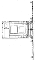
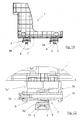
- One is too fixing unit 1 as an adapter for a not closer designed flight data memory formed.
- the Fasteners 2, where the adapter 1 are to be attached are as mounting rails or formed as a seat rails 2. It is intended that the adapter 1 is attached to two seat rails 2 becomes.
- the seat rails 2 represent in Ausnaturalüngsbeispiel Seat rails of an aircraft or of an aircraft, with further arrangements for Carrying out a picture flight, for example one digital camera, is equipped.
- the embodiment shows only one of the possible Fields of application of the device according to the invention.
- any unit of any desired fastening devices preferably mounting rails, be attached. These may be fasteners or mounting rails of any Act vehicle. Under the term vehicle should be both land and air and water vehicles be understood.
- the device according to the invention is particularly suitable for use in vehicles, in the usual way with fixing rails, especially with seat rails provided such as buses, military vehicles, Lorries and aircraft the case is.
- the invention is not in the embodiment illustrated embodiment limited.
- Fig. 1 shows the recording of the flight data memory provided adapter 1, which is attached to two seat rails 2 shall be.
- to Connection of the mounting adapter 3a, 3b with the Seat rails 2 are specifically to the seat rails 2 adapted fastening members 4 are provided.
- the fasteners as known Seat rail fittings 4 formed.
- the seat rail fittings 4 each have a cone socket 5 and a spherical disk 6 on. This can in a known manner a slight deviation from the intended orientation the seat rail fittings 4 and the seat rail 2 corrected become.
- a mounting adapter 3a is designed such that a pivoting movement of the adapter 1 to the seat rails 2 is possible.
- the pivoting movement enabling Fixing adapter 3a has for this purpose a hinge connection 7, over which the adapter 1 with the associated seat rail 2 is connected.
- the articulation is 7 by a bolt 8 and holes 9, 10 are formed.
- the mounting adapter 3a is in two parts formed, wherein the two parts 3a 'and 3a " be connected by the bolt 8.
- One first part 3a 'of the mounting adapter 3a is over the seat rail fittings 4 with the associated seat rail 2 connected.
- the second part 3a "of the mounting adapter 3a is with the adapter 1 for the flight data memory by means of a not shown Connected screw.
- this has the Adapter 1 facing second part 3a "of the mounting adapter 3a has a rocker-like structure, i. the Part 3a "tapers, starting from the for recording provided for the bolt 8 bore 10 in the direction on the adapter 1. This is the pan or rocking motion of the adapter 1 to the seat rails 2 constructive through the second part 3a "of the mounting adapter 3a not restricted.
- the adapter 1 is thus on a three-point support (the two seat rail fittings 4 of the Mounting adapter 3b and the bolt 8 of the mounting adapter 3a) connected to the seat rails 2.
- the adapter 1 by means of a rigid mounting adapter 3b and a substantially of two parts 3a ', 3a "formed Mounting adapter 3a with the seat rails 2 is connected. Because of the agility of the two Parts 3a 'and 3a "to each other, the distance between the seat rail fitting 4 of the two-part mounting adapter 3a and the seat rail fittings 4 of rigid mounting adapter 3b can be varied. Of the two-piece mounting adapter 3a allows that tensions and twists of the Seat rails 2 and the aircraft not on the adapter 1, but to a movement of two parts 3a ', 3a "of the two-part mounting adapter 3a lead to each other. The tension and the like are thus compensated.
- FIG. 9 the use of two fastening adapters 3a provided.
- the attachment of the adapter 1 can thus be done on two seat rails 2, the especially close together or especially far apart lie.
- a the two mounting adapter 3a (alternatively also both) is provided with two bolts 8.
- One with two Bolt 8 provided mounting adapter 3a allows Although no pivotal movement of the adapter 1 to the seat rails 2, but is by the design with two bolts 8 a particularly safe and stable arrangement of the adapter 1 allows.
- a mounting adapter 3a two bolts. 8 and a mounting adapter 3a only a bolt 8 (according to FIG. 1). This in turn creates one advantageous three-point support.
- FIGS. 1, 2 and 8 have the mounting adapter 3a, 3b for connection to the adapter 1 several mounting holes 11, which is a variable positioning of the Mounting adapter allow 3a or 3b on the adapter 1.
- the mounting adapter 3a, 3b For stable support of the adapter 1 on the Fixing adapters 3a, 3b and thus a plurality of Fixing holes 11 can be realized have the mounting adapter 3a, 3b a corresponding large bearing surface 12 on, each with the mounting holes 11 is provided.
- the Support surface 12 of the mounting adapter 3b in terms on to the implementation of the seat rail fittings 4 provided holes arranged asymmetrically.
- the support surface 12th the mounting adapter 3b in the direction of the mounting adapter 3a aligned.
- the mounting adapter 3b is mounted swiveled by 180 °, i.e. that the bearing surface 12 of the Befest Trentsigüngsadapters 3b in the opposite of the mounting adapter 3a Direction extends.
- each two seat rail fittings. 4 attached in the respective associated seat rails 2 become.
- the seat rail fittings 4 are doing with a cone socket 5 and a spherical disk 6 are provided.
- the mounting adapter 3b and the first Part 3a 'of the mounting adapter 3a placed.
- the Nuts 13 is the correspondingly assigned mounting adapter 3b and the first part 3a 'of the mounting adapter 3a bolted or attached.
- the mounting adapter 3b can now directly with the adapter 1, including two or more of the Fixing holes 11 are used.
- the Mounting adapter 3a connected to the adapter 1 can still be the second part 3a "of the mounting adapter 3a with the first part 3a 'of the mounting adapter 3a are connected.
- the Bore 9 of the first part 3a 'and the holes 10th of the second part 3a "aligned over one another and the bolt 8 is inserted and fixed accordingly.
- the first part 3a ' is now with the second part 3a "connected via a hinge connection 7, which a Pivoting movement of the adapter 1 to the seat rails 2 allows.
- the hinge joint 7 also serves as a linear guide for the movement of the two parts 3a ', 3a "to each other.
- a final operation can now be the mounting adapter 3a and its second part 3a "via two or more mounting holes 11 are bolted to the adapter 1.
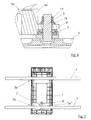
- Fig. 4 shows in detail the mounting adapter 3b an illustration of a seat rail fitting 4. Based the arrangement of a cone socket 5 and a spherical disk 6 may be a slight deviation of the seat rail fitting 4 of the intended orientation be compensated.
- the seat rail fitting 4 is in illustrated embodiment with a thread provided for screwing the nut 13.
- a washer 14 instead of another Conical socket 5 and a further spherical disk 6 are provided.
- Fig. 3 shows an enlarged view of the mounting adapter 3a.
- the postponement the two parts 3a 'and 3a "to each other takes place along the axis of the bolt 8.
- Fig. 5 shows a front view of the mounting adapter 3a with a plan view of the hinge connection 7 and the bolt 8.
- Fig. 6 shows the seat rail fitting 4 and the thereto arranged first part 3a 'of the mounting adapter 3a from a Fig. 4 offset by 90 ° representation.
- Fig. 7 shows a view of the two fastening adapters 3a, 3b from below, clearly from the pivoting the mounting adapter 3a and the possibility to move the two parts 3a 'and 3a "to each other, is apparent.
- Fig. 8 shows a plan view of the two mounting adapters 3a, 3b in a state in which each are attached to a seat rail 2.
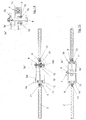
- Fig. 9 shows an alternative to the figures 1 to 8 Embodiment in which the adapter 1 for receiving of the flight data memory by means of two fastening adapters 3a is attached to the seat rails 2.
- the mounting adapter 3a, 3b are in the embodiment each arranged at the end of the adapter 1.
- the Mounting adapter 3a, 3b or their bearing surfaces 12 extend over the entire width of the Adapters 1 for receiving a flight data memory.
- the Mounting adapter 3b has viewed in cross section a U-shaped profile, wherein the mounting adapter 3b in the region of its U-shaped ends with a Through hole is provided for screwing with the associated seat rail 2 is used.
- the mounting adapter 3a also with any other longitudinal guide be provided that a sliding of the adapter 1 relative to the mounting adapter 3a and its with the Seat rail 2 connected first part 3a 'allows.
- the necessary linear guide for example as a rail, tongue and groove connection or the like be educated. It is essential, that the adapter 1 is not fixed or rigid with the two Seat rails 2 connected, but at least a seat rail 2 is movable, so tensions can be compensated.
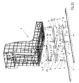
- FIG. 10 shows an exploded view of that in FIG. 9 illustrated alternative embodiment.
- Fig. 10 corresponds to the exploded view largely the exploded view shown in Fig. 1 with the exception of the alternative embodiment a mounting adapter, wherein the illustrated in Fig. 1 Mounting adapter 3b through a mounting adapter 3a is replaced, which two bolts. 8 having.
- the illustrated in Fig. 10 with two bolts 8 Mounting adapter 3a has a first part 3a ' for attachment to the adapter 1 and a second part 3a "for connection to the seat rail 2.
- the alternative shown according to the figures 9 to 14 inventive design allows the Adapter 1 for the flight data memory even after mounting on the seat rails 2 relative to the seat rails to move.
- For fixation in the desired Position has the with the two bolts. 8 provided mounting adapter 3a two cone sleeves 15th on, each keyed over two fixing screws 16 can be. After wedging the cone sleeves 15 by the fixing screws 16, the adapter 1 in the desired position arrested.
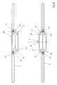
- Fig. 11 and Fig. 12 show a cross section through the with two bolts 8 provided mounting adapter 3a.
- the mode of operation results from FIGS. 11 and 12 the conical sleeves 15 for locking the bolt 8 to the second part 3a ", whereby the adapter 1 to the seat rails 2 is no longer movable.
- the others in Fig. 11 illustrated parts correspond to essentially already with respect to FIG. 2 and FIG. 3 described parts.
- FIG. 13 shows a plan view of the two mounting adapters 3a according to the figures 9 to 12 in one Condition in which these each on a seat rail. 2 are attached.
- FIG. 14 shows an enlarged sectional view of the Mounting adapter 3a in the region of one of its bolts 8. From Fig. 13 and Fig. 14 gives an illustration a conical sleeve 15 by screwing the two fixing screws 16 are keyed to the bolt 8 can.
Abstract
Description
- Fig. 1
- die erfindungsgemäße Vorrichtung mit einer zu befestigenden Einheit und zwei schienenförmigen Befestigungseinrichtungen in einer Explosionsdarstellung;
- Fig. 2
- die erfindungsgemäße Vorrichtung gemäß Fig. 1 in einer Seitenansicht im montierten Zustand;
- Fig. 3
- eine vergrößerte Einzeldarstellung gemäß dem Ausschnitt III der Fig. 2;
- Fig. 4
- eine vergrößerte Einzeldarstellung gemäß dem Ausschnitt IV der Fig. 2;
- Fig. 5
- eine vorderseitige Ansicht der erfindungsgemäßen Vorrichtung gemäß Pfeilrichtung V der Fig. 2;
- Fig. 6
- eine vergrößerte Darstellung der Einzelheit VI der Fig. 5;
- Fig. 7
- eine Darstellung der erfindungsgemäßen Vorrichtung von unten gemäß Pfeilrichtung VII der Fig. 2;
- Fig. 8
- eine Ansicht der erfindungsgemäßen Vorrichtung von oben - ohne die zu befestigende Einheit;
- Fig. 9
- eine Seitenansicht einer alternativen Ausgestaltung der erfindungsgemäßen Vorrichtung mit zwei Befestigungsadaptern, die jeweils verschiebbar ausgebildet sind;
- Fig. 10
- eine Explosionsdarstellung der erfindungsgemäßen Vorrichtung gemäß der in Fig. 9 dargestellten alternativen Ausgestaltung;
- Fig. 11
- eine Seitenansicht der erfindungsgemäßen Vorrichtung gemäß der in Fig. 9 dargestellten alternativen Ausgestaltung mit einer Schnittdarstellung der Befestigungsadapter;
- Fig. 12
- eine vergrößerte Einzeldarstellung gemäß dem Ausschnitt XII der Fig. 11;
- Fig. 13
- eine Ansicht der erfindungsgemäßen Vorrichtung gemäß der in Fig. 9 dargestellten alternativen Ausgestaltung von oben - ohne die zu befestigende Einheit, und
- Fig. 14
- eine vergrößerte Einzeldarstellung gemäß dem Ausschnitt XIV der Fig. 13.
Claims (15)
- Vorrichtung zur Befestigung einer Einheit an Befestigungseinrichtungen eines Fahrzeugs, insbesondere eines Luftfahrzeugs, mit Befestigungsgliedern, welche zur Verbindung mit den Befestigungseinrichtungen vorgesehen sind,
gekennzeichnet durch
wenigstens einen Befestigungsadapter (3a bzw. 3b), welcher einerseits mit der zu befestigenden Einheit (1) und andererseits mittels den Befestigungsgliedern (4) mit wenigstens einer Befestigungseinrichtung (2) verbindbar ist. - Vorrichtung nach Anspruch 1,
dadurch gekennzeichnet, dass
zur Befestigung der Einheit (1) zwei Befestigungsadapter (3a,3b) vorgesehen sind. - Vorrichtung nach Anspruch 1 oder 2,
dadurch gekennzeichnet, dass
wenigstens zwei Befestigungsgliedern (4) zur Befestigung eines Befestigungsadapters (3a,3b) an einer Befestigungseinrichtung (2) vorgesehen sind. - Vorrichtung nach Anspruch 1, 2 oder 3,
dadurch gekennzeichnet, dass
wenigstens ein Befestigungsadapter (3a) eine Schwenk- bzw. Wippbewegung der Einheit (1) zu der Befestigungseinrichtung (2) ermöglicht. - Vorrichtung nach Anspruch 4,
dadurch gekennzeichnet, dass
der die Schwenkbewegung ermöglichende Befestigungsadapter (3a) eine Gelenkverbindung (7) aufweist, über die die Einheit (1) mit der Befestigungseinrichtung (2) verbunden ist. - Vorrichtung nach einem der Ansprüche 1 bis 5,
dadurch gekennzeichnet, dass
wenigstens ein Befestigungsadapter (3a) einen im wesentlichen zweiteiligen Aufbau aufweist, wobei ein erster Teil (3a') des Befestigungsadapters (3a) über die Befestigungsglieder (4) mit der Befestigungseinrichtung (2) und ein zweiter Teil (3a") des Befestigungsadapters (3a) mit der Einheit (1) verbindbar ist, wobei die beiden Teile (3a',3a") des Befestigungsadapters (3a) zueinander verschiebbar sind. - Vorrichtung nach Anspruch 5 und 6,
dadurch gekennzeichnet, dass
die beiden Teile (3a',3a") des Befestigungsadapters (3a) über die Gelenkverbindung (7) miteinander verbunden sind. - Vorrichtung nach Anspruch 7,
dadurch gekennzeichnet, dass
die Gelenkverbindung (7) durch einen Bolzen (8) und Bohrungen (9,10) in den beiden Teilen (3a',3a") des Befestigungsadapters (3a) ausgebildet ist. - Vorrichtung nach einem der Ansprüche 2 bis 8,
dadurch gekennzeichnet, dass
einer der beiden zur Befestigung der Einheit (1) vorgesehenen Befestigungsadapter (3b) im wesentlichen starr ausgebildet ist, während der andere Befestigungsadapter (3a) eine Schwenkbewegung zum Ausgleich von Verspannungen und/oder Verwindungen ermöglicht. - Vorrichtung nach einem der Ansprüche 6 bis 9,
dadurch gekennzeichnet, dass
die beiden Teile (3a',3a") des im wesentlichen zweiteilig aufgebauten Befestigungsadapters (3a) so zueinander verschiebbar sind, dass der Abstand zwischen den Befestigungsgliedern (4) des zweiteiligen Befestigungsadapters (3a) und den Befestigungsgliedern (4) eines zweiten Befestigungsadapters (3b) variabel ist. - Vorrichtung nach einem der Ansprüche 1 bis 10,
dadurch gekennzeichnet, dass
der Befestigungsadapter (3a bzw. 3b) zur Verbindung mit der Einheit (1) mehrere Befestigungsbohrungen (11) aufweist, die eine variable Positionierung des Befestigungsadapters (3a bzw. 3b) an der Einheit (1) ermöglichen. - Vorrichtung nach einem der Ansprüche 1 bis 11,
dadurch gekennzeichnet, dass
die Befestigungseinrichtungen als Sitzschienen (2) eines Flugzeugs ausgebildet sind. - Vorrichtung nach einem der Ansprüche 1, bis 12,
dadurch gekennzeichnet , dass
die Befestigungsglieder als Sitzschienenfittings (4) ausgebildet sind. - Vorrichtung nach Anspruch 13,
dadurch gekennzeichnet, dass
die Sitzschienenfittings (4) jeweils eine Kegelpfanne (5) und eine Kugelscheibe (6) aufweisen. - Vorrichtung nach einem der Ansprüche 1 bis 14,
dadurch gekennzeichnet, dass
die Einheit als Adapter (1) für einen Flugdatenspeicher ausgebildet ist.
Applications Claiming Priority (2)
| Application Number | Priority Date | Filing Date | Title |
|---|---|---|---|
| DE102004013878A DE102004013878A1 (de) | 2004-03-20 | 2004-03-20 | Vorrichtung zur Befestigung einer Einheit an Befestigungseinrichtungen eines Fahrzeugs |
| DE102004013878 | 2004-03-20 |
Publications (3)
| Publication Number | Publication Date |
|---|---|
| EP1577211A2 true EP1577211A2 (de) | 2005-09-21 |
| EP1577211A3 EP1577211A3 (de) | 2015-03-04 |
| EP1577211B1 EP1577211B1 (de) | 2017-01-04 |
Family
ID=34833228
Family Applications (1)
| Application Number | Title | Priority Date | Filing Date |
|---|---|---|---|
| EP05002636.8A Not-in-force EP1577211B1 (de) | 2004-03-20 | 2005-02-09 | Vorrichtung zur Befestigung einer Einheit an Befestigungseinrichtungen eines Fahrzeugs |
Country Status (5)
| Country | Link |
|---|---|
| US (1) | US7618009B2 (de) |
| EP (1) | EP1577211B1 (de) |
| JP (1) | JP4708823B2 (de) |
| DE (1) | DE102004013878A1 (de) |
| ES (1) | ES2619204T3 (de) |
Families Citing this family (19)
| Publication number | Priority date | Publication date | Assignee | Title |
|---|---|---|---|---|
| DE102004013875A1 (de) * | 2004-03-20 | 2005-11-17 | Z/I Imaging Ltd., Shannon | Vorrichtung zur Befestigung einer portablen elektronischen Einheit |
| DE102006007469A1 (de) * | 2006-02-17 | 2007-08-30 | Airbus Deutschland Gmbh | Fußbodenaufbau in einem Flugzeug mit durchlaufenden Fußbodenplatten |
| US20080156233A1 (en) * | 2006-06-02 | 2008-07-03 | Andrew Paddock | Foundation adapter module and deck tile system |
| DE102006040059A1 (de) | 2006-08-26 | 2008-02-28 | Recaro Aircraft Seating Gmbh & Co. Kg | Strukturrahmen |
| DE102006061455A1 (de) * | 2006-12-23 | 2008-06-26 | DRäGER AEROSPACE GMBH | Anordnung zumindest einer Personal Service Unit in einem Fahrzeug |
| JP4985187B2 (ja) * | 2007-07-30 | 2012-07-25 | 株式会社Ihi | 直動装置 |
| US8267003B1 (en) * | 2009-08-11 | 2012-09-18 | Armorworks Enterprises LLC | Blast resistant armor mounting hardware |
| US8493715B1 (en) | 2009-09-11 | 2013-07-23 | Lockheed Martin Corporation | Automatically ejecting flight data recorder |
| US8670879B1 (en) | 2010-04-21 | 2014-03-11 | Lockheed Martin Corporation | Automatically ejecting flight data recorder |
| JP5594092B2 (ja) * | 2010-11-29 | 2014-09-24 | トヨタ紡織株式会社 | 車両用シート |
| US20120153080A1 (en) * | 2010-12-20 | 2012-06-21 | Airbus Operations Gmbh | Adapter and method for installing monuments |
| JP6102910B2 (ja) * | 2012-02-23 | 2017-03-29 | 横浜ゴム株式会社 | 航空機の化粧室ユニットの設置方法および航空機 |
| GB2501912A (en) * | 2012-05-10 | 2013-11-13 | Koller Engineering Ltd | Vehicle seat anchorage assembly |
| DE102012208718A1 (de) | 2012-05-24 | 2013-11-28 | Lufthansa Technik Ag | Bodenanbindungsbaugruppe eines Flugzeugsitzes |
| DE102013219616A1 (de) * | 2013-09-27 | 2015-04-02 | Lufthansa Technik Ag | Bodenanbindungsbaugruppe sowie Flugzeugsitz |
| GB2569303B (en) * | 2017-12-12 | 2020-09-09 | Ipeco Holdings Ltd | Mounting apparatus for a seat |
| GB2594016B (en) * | 2017-12-12 | 2022-06-08 | Ipeco Holdings Ltd | Mounting apparatus for a seat |
| GB2590751B (en) * | 2017-12-12 | 2021-12-29 | Ipeco Holdings Ltd | Mounting apparatus for a seat |
| CN110979629A (zh) * | 2019-12-13 | 2020-04-10 | 中国航空工业集团公司西安飞机设计研究所 | 基于飞机地板滑轨的固定装置 |
Family Cites Families (41)
| Publication number | Priority date | Publication date | Assignee | Title |
|---|---|---|---|---|
| US2933127A (en) * | 1958-04-11 | 1960-04-19 | Aerotec Ind Inc | Seats for conveyances |
| US3306234A (en) * | 1964-05-14 | 1967-02-28 | Boeing Co | Securing device |
| GB1356109A (en) * | 1970-08-26 | 1974-06-12 | Sperry Rand Ltd | Flight data acquisition and recording systems |
| US3730469A (en) * | 1971-12-10 | 1973-05-01 | G Shields | Adjustable drapery support with two means of vertical adjustment |
| US3876174A (en) * | 1972-05-15 | 1975-04-08 | Southwestern Ind Inc | Universally adjustable mounting apparatus |
| US4185799A (en) * | 1978-03-14 | 1980-01-29 | Boeing Commercial Airplane Company | Aircraft partition mounting assembly |
| US4771969A (en) * | 1987-07-27 | 1988-09-20 | Sabre Industries, Inc. | Leg set track fitting |
| US4911381A (en) * | 1987-12-28 | 1990-03-27 | Simula, Inc. | Energy-absorbing leg assembly for aircraft passenger seats |
| DE3804354A1 (de) * | 1988-02-12 | 1989-08-24 | Keiper Recaro Gmbh Co | Verbindungsvorrichtung, insbesondere fuer fluggastsitze |
| JP2520005B2 (ja) * | 1989-02-23 | 1996-07-31 | 小糸工業株式会社 | 衝撃エネルギ―を吸収する座席の脚構造 |
| US5058829A (en) * | 1990-01-12 | 1991-10-22 | Weber Aircraft | Seat track fitting |
| JP2874335B2 (ja) * | 1990-11-30 | 1999-03-24 | アイシン精機株式会社 | 自動車用シート装置 |
| US5178346A (en) * | 1991-07-12 | 1993-01-12 | Burns Aerospace Corporation | Track fastener apparatus and assembly |
| JP2852147B2 (ja) * | 1991-10-07 | 1999-01-27 | 三菱製鋼 株式会社 | 運搬車荷台用振動緩衝装置 |
| US5449132A (en) * | 1992-02-03 | 1995-09-12 | Weber Aircraft, Inc. | Passenger seat rear track fitting |
| FR2695885B1 (fr) * | 1992-09-22 | 1994-12-02 | Faure Bertrand Automobile | Glissière de positionnement d'un siège à mémoire interne coopérant avec le profilé fixe de la glissière. |
| FR2705314B1 (fr) * | 1993-05-14 | 1995-07-13 | Sicma Aero Seat | Piétement de siège d'appareil de transport aérien comportant un dispositif d'absorption d'énergie rapporté. |
| FR2705315B1 (fr) * | 1993-05-14 | 1995-07-13 | Sicma Aero Seat | Piétement pour siège d'appareil de transport aérien et siège comportant un tel piétement. |
| US5520357A (en) * | 1994-01-11 | 1996-05-28 | B/E Aerospace, Inc. | Fitting for an aircraft bulkhead |
| IL109446A (en) * | 1994-04-26 | 1999-09-22 | Israel Aircraft Ind Ltd | Vehicle seat |
| AUPM945094A0 (en) * | 1994-11-15 | 1994-12-08 | Beurteaux (Australia) Pty Ltd | Leg attachment system and method for seats |
| DE19641372C2 (de) * | 1996-10-08 | 2001-06-07 | Ims Morat & Soehne Gmbh | Verstellvorrichtung für einen Fahrzeugsitz |
| US6007036A (en) * | 1997-09-23 | 1999-12-28 | Rosen Products Llc | Stowable support apparatus |
| US5871318A (en) * | 1997-11-12 | 1999-02-16 | Be Aerospace, Inc. | Quick-release track fastener |
| US6086154A (en) * | 1998-03-31 | 2000-07-11 | Dura Automotive Systems, Inc. | Infinitely adjustable seat track assembly |
| EP1140552B1 (de) * | 1999-01-15 | 2005-09-14 | Johnson Controls Technology Company | Klappbarer fahrzeugsitz |
| DE19904079C2 (de) * | 1999-02-02 | 2001-10-18 | Ise Gmbh | Elektrischer Sitzversteller |
| US6260813B1 (en) * | 2000-01-10 | 2001-07-17 | November Whiskey, Inc. | Aircraft seat track anchor fitting |
| US6412864B1 (en) * | 2000-03-10 | 2002-07-02 | Be Aerospace, Inc. | Side facing multi-passenger divan assembly |
| GB0022628D0 (en) * | 2000-09-15 | 2000-11-01 | Britax Rumbold Ltd | Vehicle passenger seat |
| DE10050959B4 (de) * | 2000-10-13 | 2005-11-24 | Keiper Gmbh & Co.Kg | Sitzlängsverstellung |
| US6892995B2 (en) * | 2000-10-19 | 2005-05-17 | Intier Automotive Inc. | Positive engagement latch |
| DE10057660C1 (de) * | 2000-11-21 | 2002-04-04 | Faurecia Autositze Gmbh & Co | Kraftfahrzeugsitz mit klappbarer Rückenlehne |
| US6659402B1 (en) * | 2002-08-07 | 2003-12-09 | The Boeing Company | Modular aircraft seat system |
| US6926364B2 (en) * | 2002-08-23 | 2005-08-09 | Faurecia Automotive Seating Canada Limited | Fold flat vehicle seat in rearward position |
| US7070155B2 (en) * | 2002-11-15 | 2006-07-04 | Dura Global Technologies, Inc. | Power seat drive motor mounting arrangement and assembly method |
| US6648393B1 (en) * | 2002-12-17 | 2003-11-18 | General Motors Corporation | Lateral sliding seat |
| US7334758B2 (en) * | 2003-10-06 | 2008-02-26 | B/E Aerospace, Inc. | Attachment assembly for mounting a seat to the floor of a vehicle |
| US7021596B2 (en) * | 2004-02-11 | 2006-04-04 | Goodrich Corporation | Aircraft seat floor track quick release fitting |
| US7172155B2 (en) * | 2004-03-27 | 2007-02-06 | The Boeing Company | Seat interface for powered seat track cover |
| US7370832B2 (en) * | 2004-03-29 | 2008-05-13 | The Boeing Company | Payload to support track interface and fitting apparatus and methods |
-
2004
- 2004-03-20 DE DE102004013878A patent/DE102004013878A1/de not_active Ceased
-
2005
- 2005-02-09 EP EP05002636.8A patent/EP1577211B1/de not_active Not-in-force
- 2005-02-09 ES ES05002636.8T patent/ES2619204T3/es active Active
- 2005-03-18 US US11/084,798 patent/US7618009B2/en not_active Expired - Fee Related
- 2005-03-22 JP JP2005081662A patent/JP4708823B2/ja active Active
Non-Patent Citations (1)
| Title |
|---|
| None |
Also Published As
| Publication number | Publication date |
|---|---|
| ES2619204T3 (es) | 2017-06-23 |
| DE102004013878A1 (de) | 2005-10-06 |
| US20050224651A1 (en) | 2005-10-13 |
| EP1577211B1 (de) | 2017-01-04 |
| JP4708823B2 (ja) | 2011-06-22 |
| EP1577211A3 (de) | 2015-03-04 |
| JP2005263214A (ja) | 2005-09-29 |
| US7618009B2 (en) | 2009-11-17 |
Similar Documents
| Publication | Publication Date | Title |
|---|---|---|
| EP1577211B1 (de) | Vorrichtung zur Befestigung einer Einheit an Befestigungseinrichtungen eines Fahrzeugs | |
| DE102017131130B4 (de) | Befestigungssystem zum Befestigen einer Komponente an einer Rumpfstruktur | |
| CH685850A5 (de) | Verankerungseinrichtung | |
| DE112017005184T5 (de) | Kopfstützen-Bewegungsvorrichtung und Antriebseinheit für die Kopfstütze | |
| DE102018106325B3 (de) | Befestigungsanordnung für ein Bauteil an einem Karosserieteil eines Kraftfahrzeuges | |
| EP3275733B1 (de) | Scheinwerferbefestigungssystem für kraftfahrzeuge und verfahren | |
| EP2698295B1 (de) | Längenverstellbares Teleskoprohr, Stützwinde und Montageverfahren | |
| WO2018068778A1 (de) | Getriebe sowie kopfstütze mit wenigstens einem elektrischen antrieb, umfassend ein getriebe | |
| DE19719915C2 (de) | Gabelglied für einen Leitwerkanschluß | |
| DE102008025230B4 (de) | Befestigungsvorrichtung für ein Flugzeuginnenausstattungsbauteil | |
| DE202007015886U1 (de) | Verschiebeschwenkbeschlag | |
| DE10146930B4 (de) | Einstellmechanismus zur Längeneinstellung | |
| EP4031412B1 (de) | Beleuchtungsvorrichtung für einen kraftfahrzeugscheinwerfer | |
| DE102013202076A1 (de) | Stützvorrichtung mit Montageeinheit | |
| EP3388302A1 (de) | Fahrzeug, insbesondere schienenfahrzeug, mit einer montageschiene | |
| EP2101068A2 (de) | Justiereinheit | |
| DE102018102124A1 (de) | Kraftfahrzeug-Befestigungssystem zum Befestigen eines ersten Kraftfahrzeug-Bauteils an einem zweiten Kraftfahrzeug-Bauteil | |
| EP4219304A1 (de) | Kopplungsvorrichtung für eine verbindungsstange | |
| DE102018115725A1 (de) | Vorrichtung zum Ausgleichen von Maßtoleranzen eines Einbauelements in einer Kabine eines Fahrzeugs | |
| WO2018069234A1 (de) | Adapteranordnung, verfahren zu deren herstellung, baukastensystem für eine adapteranordnung, antriebsanordnung und verfahren zu deren herstellung sowie fahrzeugsitz | |
| DE102018112448A1 (de) | Werkzeug zur Halterung der Hochdruckwelle eines Flugzeugtriebwerks | |
| EP4286275A1 (de) | Befestigungssystem mit toleranzkompensation für einen innenraum eines luftfahrzeugs | |
| DE102021102576A1 (de) | Gelenkverbinder zum Verbinden mehrerer Bauteile | |
| DE102018128237B4 (de) | Befestigungs- und Einstellvorrichtung für eine Lampe | |
| DE102018211253B3 (de) | Anordnung umfassend einen Fahrzeugsitz und eine Liegeflächeneinheit |
Legal Events
| Date | Code | Title | Description |
|---|---|---|---|
| PUAI | Public reference made under article 153(3) epc to a published international application that has entered the european phase |
Free format text: ORIGINAL CODE: 0009012 |
|
| AK | Designated contracting states |
Kind code of ref document: A2 Designated state(s): AT BE BG CH CY CZ DE DK EE ES FI FR GB GR HU IE IS IT LI LT LU MC NL PL PT RO SE SI SK TR |
|
| AX | Request for extension of the european patent |
Extension state: AL BA HR LV MK YU |
|
| RAP1 | Party data changed (applicant data changed or rights of an application transferred) |
Owner name: Z/I IMAGING LTD. |
|
| REG | Reference to a national code |
Ref country code: HK Ref legal event code: DE Ref document number: 1085443 Country of ref document: HK |
|
| RAP1 | Party data changed (applicant data changed or rights of an application transferred) |
Owner name: LEICA GEOSYSTEMS AG |
|
| PUAL | Search report despatched |
Free format text: ORIGINAL CODE: 0009013 |
|
| AK | Designated contracting states |
Kind code of ref document: A3 Designated state(s): AT BE BG CH CY CZ DE DK EE ES FI FR GB GR HU IE IS IT LI LT LU MC NL PL PT RO SE SI SK TR |
|
| AX | Request for extension of the european patent |
Extension state: AL BA HR LV MK YU |
|
| RIC1 | Information provided on ipc code assigned before grant |
Ipc: B64D 45/00 20060101ALI20150123BHEP Ipc: B64C 1/20 20060101AFI20150123BHEP Ipc: B64D 9/00 20060101ALI20150123BHEP Ipc: H05K 7/14 20060101ALI20150123BHEP |
|
| 17P | Request for examination filed |
Effective date: 20150619 |
|
| RBV | Designated contracting states (corrected) |
Designated state(s): AT BE BG CH CY CZ DE DK EE ES FI FR GB GR HU IE IS IT LI LT LU MC NL PL PT RO SE SI SK TR |
|
| AKX | Designation fees paid |
Designated state(s): AT BE BG CH CY CZ DE DK EE ES FI FR GB GR HU IE IS IT LI LT LU MC NL PL PT RO SE SI SK TR |
|
| AXX | Extension fees paid |
Extension state: MK Extension state: HR Extension state: BA Extension state: LV Extension state: YU Extension state: AL |
|
| 17Q | First examination report despatched |
Effective date: 20160129 |
|
| GRAP | Despatch of communication of intention to grant a patent |
Free format text: ORIGINAL CODE: EPIDOSNIGR1 |
|
| INTG | Intention to grant announced |
Effective date: 20160812 |
|
| GRAS | Grant fee paid |
Free format text: ORIGINAL CODE: EPIDOSNIGR3 |
|
| GRAA | (expected) grant |
Free format text: ORIGINAL CODE: 0009210 |
|
| AK | Designated contracting states |
Kind code of ref document: B1 Designated state(s): AT BE BG CH CY CZ DE DK EE ES FI FR GB GR HU IE IS IT LI LT LU MC NL PL PT RO SE SI SK TR |
|
| REG | Reference to a national code |
Ref country code: GB Ref legal event code: FG4D Free format text: NOT ENGLISH |
|
| REG | Reference to a national code |
Ref country code: CH Ref legal event code: EP |
|
| REG | Reference to a national code |
Ref country code: AT Ref legal event code: REF Ref document number: 858944 Country of ref document: AT Kind code of ref document: T Effective date: 20170115 |
|
| REG | Reference to a national code |
Ref country code: IE Ref legal event code: FG4D Free format text: LANGUAGE OF EP DOCUMENT: GERMAN |
|
| REG | Reference to a national code |
Ref country code: CH Ref legal event code: NV Representative=s name: KAMINSKI HARMANN PATENTANWAELTE AG, LI |
|
| REG | Reference to a national code |
Ref country code: DE Ref legal event code: R096 Ref document number: 502005015480 Country of ref document: DE Ref country code: FR Ref legal event code: PLFP Year of fee payment: 13 |
|
| REG | Reference to a national code |
Ref country code: NL Ref legal event code: FP |
|
| REG | Reference to a national code |
Ref country code: SE Ref legal event code: TRGR |
|
| REG | Reference to a national code |
Ref country code: LT Ref legal event code: MG4D |
|
| PG25 | Lapsed in a contracting state [announced via postgrant information from national office to epo] |
Ref country code: BE Free format text: LAPSE BECAUSE OF NON-PAYMENT OF DUE FEES Effective date: 20170228 |
|
| REG | Reference to a national code |
Ref country code: ES Ref legal event code: FG2A Ref document number: 2619204 Country of ref document: ES Kind code of ref document: T3 Effective date: 20170623 |
|
| PG25 | Lapsed in a contracting state [announced via postgrant information from national office to epo] |
Ref country code: LT Free format text: LAPSE BECAUSE OF FAILURE TO SUBMIT A TRANSLATION OF THE DESCRIPTION OR TO PAY THE FEE WITHIN THE PRESCRIBED TIME-LIMIT Effective date: 20170104 Ref country code: IS Free format text: LAPSE BECAUSE OF FAILURE TO SUBMIT A TRANSLATION OF THE DESCRIPTION OR TO PAY THE FEE WITHIN THE PRESCRIBED TIME-LIMIT Effective date: 20170504 Ref country code: FI Free format text: LAPSE BECAUSE OF FAILURE TO SUBMIT A TRANSLATION OF THE DESCRIPTION OR TO PAY THE FEE WITHIN THE PRESCRIBED TIME-LIMIT Effective date: 20170104 Ref country code: GR Free format text: LAPSE BECAUSE OF FAILURE TO SUBMIT A TRANSLATION OF THE DESCRIPTION OR TO PAY THE FEE WITHIN THE PRESCRIBED TIME-LIMIT Effective date: 20170405 |
|
| PG25 | Lapsed in a contracting state [announced via postgrant information from national office to epo] |
Ref country code: PL Free format text: LAPSE BECAUSE OF FAILURE TO SUBMIT A TRANSLATION OF THE DESCRIPTION OR TO PAY THE FEE WITHIN THE PRESCRIBED TIME-LIMIT Effective date: 20170104 Ref country code: BG Free format text: LAPSE BECAUSE OF FAILURE TO SUBMIT A TRANSLATION OF THE DESCRIPTION OR TO PAY THE FEE WITHIN THE PRESCRIBED TIME-LIMIT Effective date: 20170404 Ref country code: PT Free format text: LAPSE BECAUSE OF FAILURE TO SUBMIT A TRANSLATION OF THE DESCRIPTION OR TO PAY THE FEE WITHIN THE PRESCRIBED TIME-LIMIT Effective date: 20170504 |
|
| REG | Reference to a national code |
Ref country code: NL Ref legal event code: MM Effective date: 20170301 |
|
| REG | Reference to a national code |
Ref country code: DE Ref legal event code: R097 Ref document number: 502005015480 Country of ref document: DE |
|
| PG25 | Lapsed in a contracting state [announced via postgrant information from national office to epo] |
Ref country code: CZ Free format text: LAPSE BECAUSE OF FAILURE TO SUBMIT A TRANSLATION OF THE DESCRIPTION OR TO PAY THE FEE WITHIN THE PRESCRIBED TIME-LIMIT Effective date: 20170104 Ref country code: IT Free format text: LAPSE BECAUSE OF FAILURE TO SUBMIT A TRANSLATION OF THE DESCRIPTION OR TO PAY THE FEE WITHIN THE PRESCRIBED TIME-LIMIT Effective date: 20170104 Ref country code: EE Free format text: LAPSE BECAUSE OF FAILURE TO SUBMIT A TRANSLATION OF THE DESCRIPTION OR TO PAY THE FEE WITHIN THE PRESCRIBED TIME-LIMIT Effective date: 20170104 Ref country code: SK Free format text: LAPSE BECAUSE OF FAILURE TO SUBMIT A TRANSLATION OF THE DESCRIPTION OR TO PAY THE FEE WITHIN THE PRESCRIBED TIME-LIMIT Effective date: 20170104 Ref country code: RO Free format text: LAPSE BECAUSE OF FAILURE TO SUBMIT A TRANSLATION OF THE DESCRIPTION OR TO PAY THE FEE WITHIN THE PRESCRIBED TIME-LIMIT Effective date: 20170104 |
|
| PLBE | No opposition filed within time limit |
Free format text: ORIGINAL CODE: 0009261 |
|
| STAA | Information on the status of an ep patent application or granted ep patent |
Free format text: STATUS: NO OPPOSITION FILED WITHIN TIME LIMIT |
|
| REG | Reference to a national code |
Ref country code: IE Ref legal event code: MM4A |
|
| PG25 | Lapsed in a contracting state [announced via postgrant information from national office to epo] |
Ref country code: MC Free format text: LAPSE BECAUSE OF FAILURE TO SUBMIT A TRANSLATION OF THE DESCRIPTION OR TO PAY THE FEE WITHIN THE PRESCRIBED TIME-LIMIT Effective date: 20170104 Ref country code: DK Free format text: LAPSE BECAUSE OF FAILURE TO SUBMIT A TRANSLATION OF THE DESCRIPTION OR TO PAY THE FEE WITHIN THE PRESCRIBED TIME-LIMIT Effective date: 20170104 Ref country code: NL Free format text: LAPSE BECAUSE OF NON-PAYMENT OF DUE FEES Effective date: 20170301 |
|
| 26N | No opposition filed |
Effective date: 20171005 |
|
| PG25 | Lapsed in a contracting state [announced via postgrant information from national office to epo] |
Ref country code: LU Free format text: LAPSE BECAUSE OF NON-PAYMENT OF DUE FEES Effective date: 20170209 |
|
| REG | Reference to a national code |
Ref country code: HK Ref legal event code: WD Ref document number: 1085443 Country of ref document: HK |
|
| REG | Reference to a national code |
Ref country code: BE Ref legal event code: MM Effective date: 20170228 |
|
| REG | Reference to a national code |
Ref country code: FR Ref legal event code: PLFP Year of fee payment: 14 |
|
| PG25 | Lapsed in a contracting state [announced via postgrant information from national office to epo] |
Ref country code: IE Free format text: LAPSE BECAUSE OF NON-PAYMENT OF DUE FEES Effective date: 20170209 Ref country code: SI Free format text: LAPSE BECAUSE OF FAILURE TO SUBMIT A TRANSLATION OF THE DESCRIPTION OR TO PAY THE FEE WITHIN THE PRESCRIBED TIME-LIMIT Effective date: 20170104 |
|
| REG | Reference to a national code |
Ref country code: HK Ref legal event code: GR Ref document number: 1085443 Country of ref document: HK |
|
| PGFP | Annual fee paid to national office [announced via postgrant information from national office to epo] |
Ref country code: GB Payment date: 20190227 Year of fee payment: 15 Ref country code: ES Payment date: 20190301 Year of fee payment: 15 Ref country code: DE Payment date: 20190227 Year of fee payment: 15 Ref country code: CH Payment date: 20190304 Year of fee payment: 15 |
|
| PGFP | Annual fee paid to national office [announced via postgrant information from national office to epo] |
Ref country code: SE Payment date: 20190227 Year of fee payment: 15 Ref country code: FR Payment date: 20190225 Year of fee payment: 15 Ref country code: AT Payment date: 20190122 Year of fee payment: 15 |
|
| PG25 | Lapsed in a contracting state [announced via postgrant information from national office to epo] |
Ref country code: HU Free format text: LAPSE BECAUSE OF FAILURE TO SUBMIT A TRANSLATION OF THE DESCRIPTION OR TO PAY THE FEE WITHIN THE PRESCRIBED TIME-LIMIT; INVALID AB INITIO Effective date: 20050209 |
|
| PG25 | Lapsed in a contracting state [announced via postgrant information from national office to epo] |
Ref country code: CY Free format text: LAPSE BECAUSE OF NON-PAYMENT OF DUE FEES Effective date: 20170104 |
|
| PG25 | Lapsed in a contracting state [announced via postgrant information from national office to epo] |
Ref country code: TR Free format text: LAPSE BECAUSE OF FAILURE TO SUBMIT A TRANSLATION OF THE DESCRIPTION OR TO PAY THE FEE WITHIN THE PRESCRIBED TIME-LIMIT Effective date: 20170104 |
|
| REG | Reference to a national code |
Ref country code: DE Ref legal event code: R119 Ref document number: 502005015480 Country of ref document: DE |
|
| REG | Reference to a national code |
Ref country code: SE Ref legal event code: EUG |
|
| REG | Reference to a national code |
Ref country code: CH Ref legal event code: PL |
|
| REG | Reference to a national code |
Ref country code: AT Ref legal event code: MM01 Ref document number: 858944 Country of ref document: AT Kind code of ref document: T Effective date: 20200209 |
|
| GBPC | Gb: european patent ceased through non-payment of renewal fee |
Effective date: 20200209 |
|
| PG25 | Lapsed in a contracting state [announced via postgrant information from national office to epo] |
Ref country code: SE Free format text: LAPSE BECAUSE OF NON-PAYMENT OF DUE FEES Effective date: 20200210 |
|
| PG25 | Lapsed in a contracting state [announced via postgrant information from national office to epo] |
Ref country code: AT Free format text: LAPSE BECAUSE OF NON-PAYMENT OF DUE FEES Effective date: 20200209 Ref country code: CH Free format text: LAPSE BECAUSE OF NON-PAYMENT OF DUE FEES Effective date: 20200229 Ref country code: LI Free format text: LAPSE BECAUSE OF NON-PAYMENT OF DUE FEES Effective date: 20200229 |
|
| PG25 | Lapsed in a contracting state [announced via postgrant information from national office to epo] |
Ref country code: FR Free format text: LAPSE BECAUSE OF NON-PAYMENT OF DUE FEES Effective date: 20200229 Ref country code: DE Free format text: LAPSE BECAUSE OF NON-PAYMENT OF DUE FEES Effective date: 20200901 Ref country code: GB Free format text: LAPSE BECAUSE OF NON-PAYMENT OF DUE FEES Effective date: 20200209 |
|
| REG | Reference to a national code |
Ref country code: ES Ref legal event code: FD2A Effective date: 20210705 |
|
| PG25 | Lapsed in a contracting state [announced via postgrant information from national office to epo] |
Ref country code: ES Free format text: LAPSE BECAUSE OF NON-PAYMENT OF DUE FEES Effective date: 20200210 |