EP1577422B1 - Erosion and wear resistant protective structures for turbine engine components - Google Patents
Erosion and wear resistant protective structures for turbine engine components Download PDFInfo
- Publication number
- EP1577422B1 EP1577422B1 EP05251407A EP05251407A EP1577422B1 EP 1577422 B1 EP1577422 B1 EP 1577422B1 EP 05251407 A EP05251407 A EP 05251407A EP 05251407 A EP05251407 A EP 05251407A EP 1577422 B1 EP1577422 B1 EP 1577422B1
- Authority
- EP
- European Patent Office
- Prior art keywords
- shape memory
- based alloys
- turbine engine
- memory alloy
- engine component
- Prior art date
- Legal status (The legal status is an assumption and is not a legal conclusion. Google has not performed a legal analysis and makes no representation as to the accuracy of the status listed.)
- Not-in-force
Links
Images


Classifications
-
- B—PERFORMING OPERATIONS; TRANSPORTING
- B23—MACHINE TOOLS; METAL-WORKING NOT OTHERWISE PROVIDED FOR
- B23K—SOLDERING OR UNSOLDERING; WELDING; CLADDING OR PLATING BY SOLDERING OR WELDING; CUTTING BY APPLYING HEAT LOCALLY, e.g. FLAME CUTTING; WORKING BY LASER BEAM
- B23K20/00—Non-electric welding by applying impact or other pressure, with or without the application of heat, e.g. cladding or plating
- B23K20/06—Non-electric welding by applying impact or other pressure, with or without the application of heat, e.g. cladding or plating by means of high energy impulses, e.g. magnetic energy
- B23K20/08—Explosive welding
-
- F—MECHANICAL ENGINEERING; LIGHTING; HEATING; WEAPONS; BLASTING
- F01—MACHINES OR ENGINES IN GENERAL; ENGINE PLANTS IN GENERAL; STEAM ENGINES
- F01D—NON-POSITIVE DISPLACEMENT MACHINES OR ENGINES, e.g. STEAM TURBINES
- F01D5/00—Blades; Blade-carrying members; Heating, heat-insulating, cooling or antivibration means on the blades or the members
- F01D5/12—Blades
- F01D5/28—Selecting particular materials; Particular measures relating thereto; Measures against erosion or corrosion
- F01D5/288—Protective coatings for blades
-
- F—MECHANICAL ENGINEERING; LIGHTING; HEATING; WEAPONS; BLASTING
- F05—INDEXING SCHEMES RELATING TO ENGINES OR PUMPS IN VARIOUS SUBCLASSES OF CLASSES F01-F04
- F05C—INDEXING SCHEME RELATING TO MATERIALS, MATERIAL PROPERTIES OR MATERIAL CHARACTERISTICS FOR MACHINES, ENGINES OR PUMPS OTHER THAN NON-POSITIVE-DISPLACEMENT MACHINES OR ENGINES
- F05C2201/00—Metals
- F05C2201/04—Heavy metals
- F05C2201/0433—Iron group; Ferrous alloys, e.g. steel
- F05C2201/0463—Cobalt
-
- F—MECHANICAL ENGINEERING; LIGHTING; HEATING; WEAPONS; BLASTING
- F05—INDEXING SCHEMES RELATING TO ENGINES OR PUMPS IN VARIOUS SUBCLASSES OF CLASSES F01-F04
- F05C—INDEXING SCHEME RELATING TO MATERIALS, MATERIAL PROPERTIES OR MATERIAL CHARACTERISTICS FOR MACHINES, ENGINES OR PUMPS OTHER THAN NON-POSITIVE-DISPLACEMENT MACHINES OR ENGINES
- F05C2201/00—Metals
- F05C2201/04—Heavy metals
- F05C2201/0433—Iron group; Ferrous alloys, e.g. steel
- F05C2201/0466—Nickel
-
- F—MECHANICAL ENGINEERING; LIGHTING; HEATING; WEAPONS; BLASTING
- F05—INDEXING SCHEMES RELATING TO ENGINES OR PUMPS IN VARIOUS SUBCLASSES OF CLASSES F01-F04
- F05D—INDEXING SCHEME FOR ASPECTS RELATING TO NON-POSITIVE-DISPLACEMENT MACHINES OR ENGINES, GAS-TURBINES OR JET-PROPULSION PLANTS
- F05D2220/00—Application
- F05D2220/30—Application in turbines
- F05D2220/31—Application in turbines in steam turbines
-
- F—MECHANICAL ENGINEERING; LIGHTING; HEATING; WEAPONS; BLASTING
- F05—INDEXING SCHEMES RELATING TO ENGINES OR PUMPS IN VARIOUS SUBCLASSES OF CLASSES F01-F04
- F05D—INDEXING SCHEME FOR ASPECTS RELATING TO NON-POSITIVE-DISPLACEMENT MACHINES OR ENGINES, GAS-TURBINES OR JET-PROPULSION PLANTS
- F05D2230/00—Manufacture
- F05D2230/30—Manufacture with deposition of material
- F05D2230/31—Layer deposition
- F05D2230/311—Layer deposition by torch or flame spraying
-
- F—MECHANICAL ENGINEERING; LIGHTING; HEATING; WEAPONS; BLASTING
- F05—INDEXING SCHEMES RELATING TO ENGINES OR PUMPS IN VARIOUS SUBCLASSES OF CLASSES F01-F04
- F05D—INDEXING SCHEME FOR ASPECTS RELATING TO NON-POSITIVE-DISPLACEMENT MACHINES OR ENGINES, GAS-TURBINES OR JET-PROPULSION PLANTS
- F05D2230/00—Manufacture
- F05D2230/30—Manufacture with deposition of material
- F05D2230/31—Layer deposition
- F05D2230/312—Layer deposition by plasma spraying
-
- F—MECHANICAL ENGINEERING; LIGHTING; HEATING; WEAPONS; BLASTING
- F05—INDEXING SCHEMES RELATING TO ENGINES OR PUMPS IN VARIOUS SUBCLASSES OF CLASSES F01-F04
- F05D—INDEXING SCHEME FOR ASPECTS RELATING TO NON-POSITIVE-DISPLACEMENT MACHINES OR ENGINES, GAS-TURBINES OR JET-PROPULSION PLANTS
- F05D2230/00—Manufacture
- F05D2230/30—Manufacture with deposition of material
- F05D2230/31—Layer deposition
- F05D2230/313—Layer deposition by physical vapour deposition
-
- F—MECHANICAL ENGINEERING; LIGHTING; HEATING; WEAPONS; BLASTING
- F05—INDEXING SCHEMES RELATING TO ENGINES OR PUMPS IN VARIOUS SUBCLASSES OF CLASSES F01-F04
- F05D—INDEXING SCHEME FOR ASPECTS RELATING TO NON-POSITIVE-DISPLACEMENT MACHINES OR ENGINES, GAS-TURBINES OR JET-PROPULSION PLANTS
- F05D2230/00—Manufacture
- F05D2230/80—Repairing, retrofitting or upgrading methods
-
- F—MECHANICAL ENGINEERING; LIGHTING; HEATING; WEAPONS; BLASTING
- F05—INDEXING SCHEMES RELATING TO ENGINES OR PUMPS IN VARIOUS SUBCLASSES OF CLASSES F01-F04
- F05D—INDEXING SCHEME FOR ASPECTS RELATING TO NON-POSITIVE-DISPLACEMENT MACHINES OR ENGINES, GAS-TURBINES OR JET-PROPULSION PLANTS
- F05D2230/00—Manufacture
- F05D2230/90—Coating; Surface treatment
-
- F—MECHANICAL ENGINEERING; LIGHTING; HEATING; WEAPONS; BLASTING
- F05—INDEXING SCHEMES RELATING TO ENGINES OR PUMPS IN VARIOUS SUBCLASSES OF CLASSES F01-F04
- F05D—INDEXING SCHEME FOR ASPECTS RELATING TO NON-POSITIVE-DISPLACEMENT MACHINES OR ENGINES, GAS-TURBINES OR JET-PROPULSION PLANTS
- F05D2300/00—Materials; Properties thereof
- F05D2300/50—Intrinsic material properties or characteristics
- F05D2300/501—Elasticity
-
- F—MECHANICAL ENGINEERING; LIGHTING; HEATING; WEAPONS; BLASTING
- F05—INDEXING SCHEMES RELATING TO ENGINES OR PUMPS IN VARIOUS SUBCLASSES OF CLASSES F01-F04
- F05D—INDEXING SCHEME FOR ASPECTS RELATING TO NON-POSITIVE-DISPLACEMENT MACHINES OR ENGINES, GAS-TURBINES OR JET-PROPULSION PLANTS
- F05D2300/00—Materials; Properties thereof
- F05D2300/50—Intrinsic material properties or characteristics
- F05D2300/505—Shape memory behaviour
-
- F—MECHANICAL ENGINEERING; LIGHTING; HEATING; WEAPONS; BLASTING
- F05—INDEXING SCHEMES RELATING TO ENGINES OR PUMPS IN VARIOUS SUBCLASSES OF CLASSES F01-F04
- F05D—INDEXING SCHEME FOR ASPECTS RELATING TO NON-POSITIVE-DISPLACEMENT MACHINES OR ENGINES, GAS-TURBINES OR JET-PROPULSION PLANTS
- F05D2300/00—Materials; Properties thereof
- F05D2300/60—Properties or characteristics given to material by treatment or manufacturing
- F05D2300/611—Coating
-
- Y—GENERAL TAGGING OF NEW TECHNOLOGICAL DEVELOPMENTS; GENERAL TAGGING OF CROSS-SECTIONAL TECHNOLOGIES SPANNING OVER SEVERAL SECTIONS OF THE IPC; TECHNICAL SUBJECTS COVERED BY FORMER USPC CROSS-REFERENCE ART COLLECTIONS [XRACs] AND DIGESTS
- Y10—TECHNICAL SUBJECTS COVERED BY FORMER USPC
- Y10S—TECHNICAL SUBJECTS COVERED BY FORMER USPC CROSS-REFERENCE ART COLLECTIONS [XRACs] AND DIGESTS
- Y10S420/00—Alloys or metallic compositions
- Y10S420/902—Superplastic
-
- Y—GENERAL TAGGING OF NEW TECHNOLOGICAL DEVELOPMENTS; GENERAL TAGGING OF CROSS-SECTIONAL TECHNOLOGIES SPANNING OVER SEVERAL SECTIONS OF THE IPC; TECHNICAL SUBJECTS COVERED BY FORMER USPC CROSS-REFERENCE ART COLLECTIONS [XRACs] AND DIGESTS
- Y10—TECHNICAL SUBJECTS COVERED BY FORMER USPC
- Y10T—TECHNICAL SUBJECTS COVERED BY FORMER US CLASSIFICATION
- Y10T428/00—Stock material or miscellaneous articles
- Y10T428/12—All metal or with adjacent metals
- Y10T428/12493—Composite; i.e., plural, adjacent, spatially distinct metal components [e.g., layers, joint, etc.]
- Y10T428/12535—Composite; i.e., plural, adjacent, spatially distinct metal components [e.g., layers, joint, etc.] with additional, spatially distinct nonmetal component
- Y10T428/12611—Oxide-containing component
-
- Y—GENERAL TAGGING OF NEW TECHNOLOGICAL DEVELOPMENTS; GENERAL TAGGING OF CROSS-SECTIONAL TECHNOLOGIES SPANNING OVER SEVERAL SECTIONS OF THE IPC; TECHNICAL SUBJECTS COVERED BY FORMER USPC CROSS-REFERENCE ART COLLECTIONS [XRACs] AND DIGESTS
- Y10—TECHNICAL SUBJECTS COVERED BY FORMER USPC
- Y10T—TECHNICAL SUBJECTS COVERED BY FORMER US CLASSIFICATION
- Y10T428/00—Stock material or miscellaneous articles
- Y10T428/12—All metal or with adjacent metals
- Y10T428/12493—Composite; i.e., plural, adjacent, spatially distinct metal components [e.g., layers, joint, etc.]
- Y10T428/12771—Transition metal-base component
- Y10T428/12806—Refractory [Group IVB, VB, or VIB] metal-base component
-
- Y—GENERAL TAGGING OF NEW TECHNOLOGICAL DEVELOPMENTS; GENERAL TAGGING OF CROSS-SECTIONAL TECHNOLOGIES SPANNING OVER SEVERAL SECTIONS OF THE IPC; TECHNICAL SUBJECTS COVERED BY FORMER USPC CROSS-REFERENCE ART COLLECTIONS [XRACs] AND DIGESTS
- Y10—TECHNICAL SUBJECTS COVERED BY FORMER USPC
- Y10T—TECHNICAL SUBJECTS COVERED BY FORMER US CLASSIFICATION
- Y10T428/00—Stock material or miscellaneous articles
- Y10T428/12—All metal or with adjacent metals
- Y10T428/12493—Composite; i.e., plural, adjacent, spatially distinct metal components [e.g., layers, joint, etc.]
- Y10T428/12771—Transition metal-base component
- Y10T428/12861—Group VIII or IB metal-base component
- Y10T428/12944—Ni-base component
Definitions
- the present disclosure generally relates to erosion and wear resistant protective structures in the forms of coatings or shields for turbine engine components, and more particularly, to shape memory alloy protective structures for providing erosion resistance for turbine engine components.
- Erosion and wear resistant protective structures in the forms of coatings and shields have found various applications in turbine engines.
- abrasive, wear-resistant coatings are frequently deposited on the outer tips of turbine blades. Such coatings are generally employed to decrease the rate of wear/erosion of the blade due to contact of the blade with its surrounding shroud.
- Other wear resistant coatings are placed on leading edges of turbine blades to decrease wear (by erosion) due to contact with environmental particulates (e.g., dirt, sand, and the like) that enter the turbine engine during operation.
- Still another type of wear coating is placed on parts of the turbine engine that are susceptible to wear due to part-to-part contact during operation. For example, in the high-pressure turbine (HPT) and low-pressure turbine (LPT) sections of an engine, wear coatings are placed on nozzle wear pads that rub against an adjacent structure, such as a shroud hanger or a pressure balance seal.
- HPT high-pressure turbine
- LPT low-pressure turbine
- erosion resistant protective structures in the form of coatings and shields have been formed on turbine components that exhibit distress from water or other types of liquid droplet erosion.
- water droplets can deposit on the stationary buckets, i.e., nozzles, where they coalesce into films or rivulets and slowly move to the trailing edge of the nozzle.
- the films and/or rivulets are removed from the stationary bucket by the steam flow in the form of large drops.
- These large drops impact the later stages of rotating buckets at a speed approximately equal to the circumferential velocity of the rotating buckets.
- the impact of water drops generates an impulsive contact pressure on the blade material surface causing progressive loss of bucket material, i.e., erosion.
- the resulting erosion of the steam turbine engine components can cause power loss, can effect turbine efficiency, and bucket lifetime, among others.
- the blades in the last few rows of blades in a low-pressure steam turbine are formed by forging a ferrous alloy containing a relatively high chromium content.
- a ferrous alloy containing a relatively high chromium content.
- One such alloy contains approximately 15.5 to 17.5% chromium and 3.0 to 5.0% nickel.
- Another alloy contains 11.5 to 13.0% chromium.
- Still other protective structures in the forms of coatings and shields are formed of cobalt based alloys such as those commercially available under the trademark Stellite® from the Deloro Stellite Company. Although these protective structures provide better erosion resistance than base metal, their erosion resistance is not optimum, still resulting in large non-recoverable efficiency loss.
- the affixment of protective structures onto a turbine blade also results in reliability problems, such as stress corrosion cracking as well as manufacturing defects in the forms of voids or cracks of the integrated blade structure.
- EP-A-1054077 discloses a titanium aluminide turbine blade which has a protective coating applied to the aerofoil and the platform.
- the protective coating comprises austenitic stainless steel.
- a chromium oxide layer is formed on the protective coating.
- the protective coating and chromium oxide layer provides oxidation and sulphidation resistance for the titanium aluminide article.
- US-A-5956845 discloses a method of repairing an engine airfoil part.
- the attributes of a final workpiece produce are selected, an appropriate substrate composition is determined depending on the selected attributes and a workpiece substrate is formed to near-finished dimensions.
- An appropriate coating material composition is determined depending on the selected attributes.
- the workpiece substrate is prepared for a high-density coating process.
- the high density-coating process such as HVOF thermal spray, is performed to coat the workpiece substrate with the coating material.
- the coating material is built-up to a thickness effective to obtain desired finished dimensions after performing a hot isostatic pressing treatment.
- the appropriate hot isostatic pressing treatment parameters are determined.
- the hot isostatic pressing treatment is performed on the coated workpiece substrate to obtain a metal product having the desired finished dimensions and diffusion bonding between the coating material and the workpiece substrate.
- US-A-2003/0194320 discloses a damped blade that includes a blade structural member defining at least one coolant channel and a liner formed of a shape memory alloy extending at least partially along the at least one coolant channel defined by the blade structural member.
- the shape memory alloy that forms the liner is maintained generally at its transition temperature by means of coolant circulated through the coolant channel.
- the shape memory alloy that forms the liner will resist the onset of vibrations within the blade, thereby effectively damping blade vibrations.
- US-A-5448828 discloses a process for preparing wear-resistant edges on turbine blades, e.g. in the area of the upper leading edge of the blade and on the cover sheet, preferably for steam turbines made of chromium steels and/or titanium-based alloys including preparing a recess on the corresponding area of the blade, preferably by forging or machining, prior to the application of the edge protection, applying a powder layer in the corresponding area by low-pressure plasma spraying or according to the encapsulation technique, and subsequently compacting the powder layer by hot isostatic pressing (HIP). The diffuse binding to the base material of the blade is thus achieved.
- HIP hot isostatic pressing
- JP-A-03150331 discloses manufacturing an erosion-resistant alloy having good erosion resistance and able to be coated on a titanium alloy by mixing ceramic powder with titanium material powder in a specified ratio, firing the mixture in vacuum and compacting it by hot isostatic pressing treatment.
- JP-A-03036230 discloses manufacturing an alloy steel having excellent erosion resistance by mixing metallic powder and ceramic powder, sintering the mixed powder, thereafter subjecting it to hot isostatic pressing treatment and executing heating at a specified temperature of 400 to 800°C.
- DE-A-2551895 discloses repairing turbine parts in which a layer of steel and a plug of steel having an austenitic content greater than that of the layer of steel are heat treated.
- a turbine engine component comprised of a substrate; and an erosion resistant protective structure formed on the substrate, the erosion resistant protective structure comprising a shape memory alloy.
- the shape memory alloy comprises nickel-titanium based alloys, indium-titanium based alloys, nickel-aluminum based alloys, nickel-gallium based alloys, copper based alloys, gold-cadmium based alloys, iron-platinum based alloys, iron-palladium based alloys, silver-cadmium based alloys, indium-cadmium based alloys, manganese-copper based alloys, ruthenium-niobium based alloys, ruthenium-tantalum based alloys, titanium based alloys, iron-based alloys, or combinations comprising at least one of the foregoing alloys.
- the turbine engine component comprises a substrate; a diffusion-controlling layer affixed to the substrate; and an erosion resistant protective structure affixed to the diffusion layer, wherein the erosion resistant protective structure comprises a shape memory alloy.
- the coatings comprise a shape memory alloy and provide erosion and/or wear resistance.
- the terms "erosion resistant” and “wear resistant” are interchangeable and are intended to infer the same phenomena, i.e., a reduction in the loss of base material, such as a turbine component, upon impact with particulate matter and/or liquid.
- the shape memory alloy protective structure can be selectively formed on those regions of the turbine engine component prone to erosion and wear or may be disposed on all surfaces of the component or substrate.
- the shape memory alloy protective structure can be formed on the turbine nozzle, shroud, shroud hanger, stationary bucket, airfoil, fan blades, pressure balance seal, combustor component, and the like. It has been found that the shape memory alloy protective structure advantageously absorbs stress waves related to liquid and/or particulate impact and unlike other prior art coatings, resists high cycle fatigue.
- Turbine engine components are generally formed of a high-temperature alloy and/or superalloys and are known for high temperature performance in terms of tensile strength, creep resistance, oxidation resistance, and corrosion resistance, for example, nickel-based alloys, cobalt-based alloy, titanium-based alloys and so forth.
- Other high temperature alloys may also be treated according to the various embodiments of the present disclosure, such as ferritic-based alloys used in lower temperature environments, including the low-pressure stage of a steam turbine engine, e.g., 12-Cr steel.
- the superalloy is typically a nickel-based or a cobalt-based alloy, wherein the amount of nickel or cobalt in the superalloy is the single greatest element by weight.
- Illustrative nickel-based superalloys include at least about 40 weight percent (wt%) nickel (Ni), and at least one component from the group consisting of cobalt (Co), chromium (Cr), aluminum (AI), tungsten (W), molybdenum (Mo), titanium (Ti), and iron (Fe).
- nickel-based superalloys examples include directionally solidified and single crystal superalloys.
- Illustrative cobalt-base superalloys include at least about 30 wt % Co, and at least one component from the group consisting of nickel, chromium, aluminum, tungsten, molybdenum, titanium, and iron.
- cobalt- based superalloys are designated by the trade names Haynes ® , Nozzaloy ® , Stellite ® and Ultimet ® .
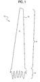
- FIG. 1 illustrates, in perspective, an exemplary turbine component that can be treated with the erosion resistant protective structures of the present disclosure.
- the exemplary turbine component is a steam turbine bucket 10 of the type commonly employed at a final stage of a low-pressure turbine for a steam turbine.
- the bucket 10 generally includes a dovetail portion 12 and a blade portion 14.
- the dovetail portion is mounted to a rotational shaft (not shown) by means of pins or the like. While the drawing depicts a single blade, the engine typically has a plurality of blades mounted on the rotational shaft. The blades rotate within an area defined by a shroud, which is generally supported by a shroud hanger.
- the shape memory alloy protective structure can be applied on any one of or any combination of the nozzle, the blade, the shroud, and the shroud hanger.
- the erosion resistant protective structure is formed on those regions of the turbine component prone to liquid erosion, e.g., regions subject to impaction of water droplets during operation, and the like.
- the shape memory alloy is preferably applied at about a leading edge 16 of the blade portion 14. It has been found that the leading edge 16 is most susceptible to liquid erosion.
- Figure 2 pictorially illustrates a leading edge of a prior art bucket exhibiting the deleterious effects caused by water erosion during operation thereof. The bucket does not include the shape memory alloy protective structure.
- the superelastic properties, among others, of the shape memory alloys provide erosion and wear resistant properties caused by impact of the particulates and/or liquid.
- Shape memory alloys typically exist in several different temperature-dependent phases. The most commonly utilized of these phases are the so-called martensite and austenite phases. In the following discussion, the martensite phase generally refers to the more deformable, lower temperature phase whereas the austenite phase generally refers to the more rigid, higher temperature phase.
- austenite start temperature A s
- austenite finish temperature A f
- the shape memory alloy When the shape memory alloy is in the austenite phase and is cooled, it begins to change into the martensite phase, and the temperature at which this phenomenon starts is referred to as the martensite start temperature (M s ).
- the temperature at which martensite finishes transforming to the martensite phase is called the martensite finish temperature (M f ).
- the shape memory alloys are soft and easily deformable in their martensitic phase and are hard, stiff, and/or rigid in the austenitic phase.
- Shape memory alloys can exhibit a one-way shape memory effect, an intrinsic two-way effect, or an extrinsic two-way shape memory effect depending on the alloy composition and processing history.
- Annealed shape memory alloys typically only exhibit the one-way shape memory effect. Sufficient heating subsequent to low-temperature (below M f ) deformation of the shape memory material will induce the martensite to austenite type transition, and the material will recover the original, high-temperature (above A f ) shape. Hence, one-way shape memory effects are only observed upon heating.
- Intrinsic and extrinsic two-way shape memory materials are characterized by a shape transition both upon heating from the martensite phase to the austenite phase, as well as an additional shape transition upon cooling from the austenite phase back to the martensite phase.
- Shape memory alloy protective structures that exhibit an intrinsic shape memory effect are fabricated from a shape memory alloy composition that will automatically reform themselves as a result of the above noted phase transformations.
- Intrinsic two-way shape memory behavior must be induced in the shape memory material through processing. Such procedures include extreme deformation of the material while in the martensite phase, heating-cooling under constraint or load, or surface modification such as laser annealing, polishing, or shot-peening.
- protective structures that exhibit the extrinsic two-way shape memory effects are composite or multi-component materials that combine a shape memory alloy composition that exhibits a one-way effect with another element that provides a restoring force to reform the protective structure.
- shape memory alloys can exhibit superelastic behavior.
- Superelastic behavior results if the shape memory alloy is deformed at a temperature that is slightly above its transformation temperature, A s , with a stress/strain level not above its recoverable range.
- the superelastic effect is caused by a stress-induced formation of some martensite above its normal temperature, M s . Because it has been formed above its normal temperature, the martensite reverts immediately to an undeformed austenite as soon as the stress is removed.
- the shape memory alloy coating can provide a very springy, "rubberlike" elasticity so as to absorb the impact of particulate matter and liquid.
- superelastic shape memory alloys can be strained several times more than ordinary metal alloys without being plastically deformed, which reflect its rubber-like behavior. It is, however, only observed over a specific temperature range.
- the highest temperature at which martensite can no longer stress induced is generally called M d .
- M d shape memory alloys are deformed and hardened like ordinary materials by dislocation multiplication or slipping. Below A s , the material is martensitic and does not recover. Thus, superelasticity appears in a temperature range from near A f and up to M d . The largest ability to recover occurs close to A f .
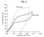
- FIG. 3 graphically illustrates compressive stress as a function of compressive strain for a turbine component formed of a Ti-based alloy relative to a NiTiCr shape memory alloy.
- the NiTiCr shape memory alloy comprised 56 wt% Ni, 43 wt% Ti, and 1 wt% Cr.
- the shape memory alloy provides greater energy absorption and superelasticity properties relative to the Ti-based alloy, which has been found to directly translate into improved erosion resistance relative to the base material. It is believed that the shape memory alloy absorbs the stress wave associated with the impacting particles or liquid droplets and, as shown, inherently resists erosion damage due to its superelasticity.
- Martensitic shape memory alloys inherently have good damping capability due to the internal friction of twin boundaries.
- the martensitic materials show a much smaller work hardening effect beyond its yielding point as comparing to its austenitic counterpart or a typical metallic material. Those effects also can advantageously provide martensitic shape memory alloy with good erosion resistance.
- Suitable shape memory alloy materials for providing erosion resistance to surfaces of turbine components include, but are not intended to be limited to, nickel-titanium based alloys, indium-titanium based alloys, nickel-aluminum based alloys, nickel-gallium based alloys, copper based alloys (e.g., copper-zinc alloys, copper-aluminum alloys, copper-gold, and copper-tin alloys), gold-cadmium based alloys, silver-cadmium based alloys, indium-cadmium based alloys, manganese-copper based alloys, iron-platinum based alloys, iron-palladium based alloys, ruthenium-niobium based alloys, ruthenium-tantalum based alloys, titanium based alloys, iron-based alloys, and the like.
- nickel-titanium based alloys indium-titanium based alloys, nickel-aluminum based alloys, nickel-gallium
- the alloys can be binary, ternary, or any higher order so long as the alloy composition exhibits a shape memory effect, e.g., change in shape orientation, changes in yield strength, and/or flexural modulus properties, damping capacity, superelasticity, and the like upon heating or cooling through phase transition temperatures or upon stress or strain induced phase transition.
- a preferred shape memory alloy is a nickel-titanium based alloy commercially available under the trademark NITINOL from Shape Memory Applications, Inc. Selection of a suitable shape memory alloy composition depends on the temperature range where the component will operate.
- shape memory alloy is also intended to include shape memory alloy composites, wherein the shape memory alloy based composites comprises a matrix of shape memory alloy and at least one hard particulate phase.
- the hard particulate phase comprises borides, oxides, nitrides, carbides, or combinations comprising at least one of the foregoing particulates.
- the shape memory alloy composites comprises a multilayer structure of the shape memory alloy alternating with a metallic or a ceramic layer with the same or different thickness as the shape memory alloy layer.
- the ceramic layer is preferably selected from the group consisting of borides, oxides, nitrides, carbides, TiN, Y 2 O 3 , and TaC.
- the metallic layer is preferably selected from the group consisting of Ti, Ni, Co, Ti-based alloys, Ni-based alloys, Co-based alloys, Fe-based alloys, and the like.
- the composite may further include ultra-fine grained materials such as may be produced by severe plastic deformation processes generally known by those skilled in the art.
- suitable severe plastic deformation processes for obtaining the desired grains sizes include, but are not intended to be limited to, ball milling, impact deformation, shot peening, high pressure torsion processing, and the like.
- Preferred grain sizes are less than 2 micrometers, with grain sizes less than 1 micrometer more preferred, and with grain sizes less 100 nanometers even more preferred.
- Suitable ultra-fine grained materials are characterized by high hardness, no recrystallization, slow grain growth upon annealing, and low dislocation density interior of grains. While not wanting to be bound by theory, it is believed that the ultra-fine grained materials in the composite will prevent and/or deflect propagation of cracks within the coating.
- the alloying elements and compositions of the shape memory alloys are chosen based on the desired superelastic behavior and transformation temperatures. It has been found that interdiffusion between the substrate and the shape memory alloy can lead to brittle Ti and Fe intermetallic compounds that can weaken the so-formed bond between the two materials.
- a diffusion-controlling layer is affixed prior to affixing the shape memory alloy protective structure.
- the diffusion-controlling layer is characterized by a high solubility for Ti and Ni/Fe without limited formation of brittle intermetallic compound, and/or with an absence for forming low melting phases with Ti or Ni or Fe. It has been found that some shape memory alloy protective structures form undesirable phases at the interface between the base material and the shape memory alloy. The use of the diffusion-controlling layer substantially prevents interdiffusion and formation of undesirable phases.
- the diffusion-controlling layer is a pure metal or a metal alloy that enhances the metallurgical bonding properties of the shape memory alloy to the turbine component.
- these metals are Nb, Hf, Ta, and Zr.
- the shape memory alloy is isolated from direct contact with the base material, e.g., titanium alloys, ferrous alloys, and the like.
- the thickness of the diffusion-controlling layer is selected to substantially prevent interdiffusion of the shape memory alloy with the turbine component alloy composition. Preferred thicknesses are about 0.013 mm (0.5 mil) to about 2.54 mm (100 mil), and with about 0.025 mm (1 mil) to about 0.13 mm (5 mil) more preferred.
- the various methods generally include coating, bonding, or fixedly joining the shape memory alloy to the the diffusion-controlling layer.
- the shape memory alloy can be affixed to the diffusion control layer turbine component by a diffusion bonding process such as a hot-isotactic pressing (HIP) process.
- HIP hot-isotactic pressing
- An exemplary HIP process for affixing a NiTi based alloy to a diffusion control layer on the turbine component formed from steel or a titanium based alloy employs a temperature preferably less than 950°C and a pressure greater than 138 MPa (20ksi). More preferably, the HIP process employs a temperature of about 700°C to about 900°C and a pressure of 138 MPa (20 ksi) to about 276 MPa (40 ksi).
- the preferred temperature and the area reduction ratios are preferably at a temperature less than 950°C and an area reduction equal to or greater than 2:1. More preferably, the extrusion process employs a temperature of about 700°C to about 900°C with the area reduction ratio of 2:1 to 8:1.
- a vapor grown shape memory alloy coating can be deposited directly from a gas phase onto a surface of the diffusion control layer to form an integral coating.
- the thickness of the shape memory alloy protective structure is chosen to provide resiliency and flexibility to those surfaces prone to erosion by particles and/or liquid.
- the thickness of the shape memory alloy coating should also be of a thickness effective to provide the desired shape memory effect. Suitable thicknesses are about 0.013mm (0.5 mils) to about 5 cm (2 inches), with about 5.1 mm (200 mils) to about 2.5 cm (1 inch) more preferred.
- the shape memory alloy protective structure can be imparted by optional surface treatments such as application of high-energy beams from ion or laser sources or other mechanical means such as by shot peening or polishing.
- the shape memory alloy coating is exposed to a heat treatment process or an aging process may be employed.
- the heat treatment process preferably includes exposing the turbine component to a temperature of about 815°C to about 1,010°C for a period of up to about 4 hours.
- the aging process preferably includes heating the component to about 480°C to about 815°C for a period of up to about 12 hours.
- a combination of the heat treatment process and aging process is also contemplated herein.
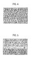
- Comparative Example 1 a NiTi shape memory alloy (56 wt% Ni, 44 wt% Ti) was joined to a Fe-based alloy using a HIP device at a temperature of 900°C and a pressure of about 207 MPa (30 ksi). A cross section of the so-formed joint is illustrated in Figure 4 .
- Example 2 In this example, the NiTiCr shape memory alloy was joined to the Ti-based alloy with a Nb diffusion-controlling layer sandwiched therebetween. A cross section of the so-formed joint is illustrated in Figure 5 . No cracking is observed by optical and scanning electron microscopy and the joint formed appears to be firmly bonded.
- Example 3 In this example, a NiTiFe alloy (52 wt% Ni, 45 wt% Ti, and 3 wt% Fe) a Nb diffusion-controlling layer, and a Ti-based alloy were co-extruded using the extrusion process at a temperature of 900°C and an area reduction ratio of 4:1. The NiTi based alloy and Ti-based alloy were preheated for 2 hours at a temperature of 900°C. A cross section of the so-formed joint is illustrated in Figure 6 . The interface between the NiTiFe and Ti-based alloy with the Nb diffusion-controlling layer appears uncracked and firmly bonded.
- Example 4 according to the state of the art.
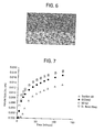
- volume loss as a function of time was measured using a liquid impact erosion test.
- Test samples were exposed to a water column at room temperature having an impinging velocity of 229 m (750 feet) per second. The diameter of the water column was 0.81 mm (0.032 inches).
- Figure 7 graphically illustrates the results for various materials commonly employed for the fabrication of turbine components.
- Figure 8 graphically illustrates the results for shape memory alloys compared to Stellite 6B and a Ti-based alloys, two alloys commonly used for fabrication of erosion shields and turbine components, respectively.
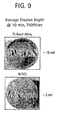
- Figure 9 pictorially illustrates erosion of a Ti-based alloy compared to NiTiCr alloy after exposure top the water erosion test for 10 minutes.
- the average erosion depth for the Ti-based alloy was about 0.41 mm (16 mils) whereas the average erosion depth for the NiTiCr shape memory alloy was about 0.13 mm (5 mils).
- shape memory alloys on the turbine component alloy provide improved erosion resistance over time relative to the other materials employed for the fabrication of turbine components.
Description
- The present disclosure generally relates to erosion and wear resistant protective structures in the forms of coatings or shields for turbine engine components, and more particularly, to shape memory alloy protective structures for providing erosion resistance for turbine engine components.
- Erosion and wear resistant protective structures in the forms of coatings and shields have found various applications in turbine engines. For example, abrasive, wear-resistant coatings are frequently deposited on the outer tips of turbine blades. Such coatings are generally employed to decrease the rate of wear/erosion of the blade due to contact of the blade with its surrounding shroud. Other wear resistant coatings are placed on leading edges of turbine blades to decrease wear (by erosion) due to contact with environmental particulates (e.g., dirt, sand, and the like) that enter the turbine engine during operation. Still another type of wear coating is placed on parts of the turbine engine that are susceptible to wear due to part-to-part contact during operation. For example, in the high-pressure turbine (HPT) and low-pressure turbine (LPT) sections of an engine, wear coatings are placed on nozzle wear pads that rub against an adjacent structure, such as a shroud hanger or a pressure balance seal.
- In addition to abrasive and frictional wear, erosion resistant protective structures in the form of coatings and shields have been formed on turbine components that exhibit distress from water or other types of liquid droplet erosion. As it is also well known in the art of steam turbines, there is a tendency for water droplets to form in the steam flowing through the lowest pressure portions of low-pressure steam turbines. The droplets can deposit on the stationary buckets, i.e., nozzles, where they coalesce into films or rivulets and slowly move to the trailing edge of the nozzle. Eventually, the films and/or rivulets are removed from the stationary bucket by the steam flow in the form of large drops. These large drops impact the later stages of rotating buckets at a speed approximately equal to the circumferential velocity of the rotating buckets. The impact of water drops generates an impulsive contact pressure on the blade material surface causing progressive loss of bucket material, i.e., erosion. The resulting erosion of the steam turbine engine components can cause power loss, can effect turbine efficiency, and bucket lifetime, among others.
- Typically, the blades in the last few rows of blades in a low-pressure steam turbine are formed by forging a ferrous alloy containing a relatively high chromium content. One such alloy contains approximately 15.5 to 17.5% chromium and 3.0 to 5.0% nickel. Another alloy contains 11.5 to 13.0% chromium. Still other protective structures in the forms of coatings and shields are formed of cobalt based alloys such as those commercially available under the trademark Stellite® from the Deloro Stellite Company. Although these protective structures provide better erosion resistance than base metal, their erosion resistance is not optimum, still resulting in large non-recoverable efficiency loss. In addition, the affixment of protective structures onto a turbine blade also results in reliability problems, such as stress corrosion cracking as well as manufacturing defects in the forms of voids or cracks of the integrated blade structure.
- Accordingly, a continuing need exists in the art for improved erosion and wear resistant protective structures.
-
EP-A-1054077 discloses a titanium aluminide turbine blade which has a protective coating applied to the aerofoil and the platform. The protective coating comprises austenitic stainless steel. A chromium oxide layer is formed on the protective coating. The protective coating and chromium oxide layer provides oxidation and sulphidation resistance for the titanium aluminide article. -
US-A-5956845 discloses a method of repairing an engine airfoil part. The attributes of a final workpiece produce are selected, an appropriate substrate composition is determined depending on the selected attributes and a workpiece substrate is formed to near-finished dimensions. An appropriate coating material composition is determined depending on the selected attributes. The workpiece substrate is prepared for a high-density coating process. The high density-coating process, such as HVOF thermal spray, is performed to coat the workpiece substrate with the coating material. The coating material is built-up to a thickness effective to obtain desired finished dimensions after performing a hot isostatic pressing treatment. The appropriate hot isostatic pressing treatment parameters are determined. The hot isostatic pressing treatment is performed on the coated workpiece substrate to obtain a metal product having the desired finished dimensions and diffusion bonding between the coating material and the workpiece substrate. -
US-A-2003/0194320 discloses a damped blade that includes a blade structural member defining at least one coolant channel and a liner formed of a shape memory alloy extending at least partially along the at least one coolant channel defined by the blade structural member. The shape memory alloy that forms the liner is maintained generally at its transition temperature by means of coolant circulated through the coolant channel. The shape memory alloy that forms the liner will resist the onset of vibrations within the blade, thereby effectively damping blade vibrations. -
US-A-5448828 discloses a process for preparing wear-resistant edges on turbine blades, e.g. in the area of the upper leading edge of the blade and on the cover sheet, preferably for steam turbines made of chromium steels and/or titanium-based alloys including preparing a recess on the corresponding area of the blade, preferably by forging or machining, prior to the application of the edge protection, applying a powder layer in the corresponding area by low-pressure plasma spraying or according to the encapsulation technique, and subsequently compacting the powder layer by hot isostatic pressing (HIP). The diffuse binding to the base material of the blade is thus achieved. -
JP-A-03150331 -
JP-A-03036230 -
DE-A-2551895 discloses repairing turbine parts in which a layer of steel and a plug of steel having an austenitic content greater than that of the layer of steel are heat treated. - According to the present invention, there is provided a turbine engine component comprised of a substrate; and an erosion resistant protective structure formed on the substrate, the erosion resistant protective structure comprising a shape memory alloy. The shape memory alloy comprises nickel-titanium based alloys, indium-titanium based alloys, nickel-aluminum based alloys, nickel-gallium based alloys, copper based alloys, gold-cadmium based alloys, iron-platinum based alloys, iron-palladium based alloys, silver-cadmium based alloys, indium-cadmium based alloys, manganese-copper based alloys, ruthenium-niobium based alloys, ruthenium-tantalum based alloys, titanium based alloys, iron-based alloys, or combinations comprising at least one of the foregoing alloys.
- The turbine engine component comprises a substrate; a diffusion-controlling layer affixed to the substrate; and an erosion resistant protective structure affixed to the diffusion layer, wherein the erosion resistant protective structure comprises a shape memory alloy.
- Embodiments of the invention will now be described, by way of example, with reference to the accompanying drawings, in which:
-
Figure 1 is a perspective view of a steam turbine bucket; -
Figure 2 pictorially illustrates a prior art stream turbine bucket showing the effects of water erosion during operation; -
Figure 3 graphically illustrates compressive stress as a function of compressive strain for a NiTiCr shape memory alloy and a Ti-based alloy both embodiments according to the state of the art. -
Figure 4 is an optical micrograph of a nickel titanium shape memory alloy hot isotactic processed to a Fe-based alloy; -
Figure 5 is an optical micrograph of nickel titanium chromium shape memory alloy hot isotactic processed to a Ti-based alloy with a Nb diffusion-controlling layer; -
Figure 6 is an optical micrograph of a nickel titanium iron shape memory alloy extrusion bonded to a Ti-based alloy; -
Figure 7 graphically illustrates erosion testing results for volume loss as a function of time for various conventional bucket materials; -
Figure 8 graphically illustrates erosion testing results for volume loss as a function of time for various shape memory alloys compared to conventional bucket materials; and -
Figure 9 pictorially illustrates an end-on view of Ti-based alloy and NiTiCr shape memory alloy after exposure to a water erosion test. - Disclosed herein are protective structures in the forms of coatings or shields for surfaces of turbine engine components prone to particle and/or water erosion. The coatings comprise a shape memory alloy and provide erosion and/or wear resistance. As used herein, the terms "erosion resistant" and "wear resistant" are interchangeable and are intended to infer the same phenomena, i.e., a reduction in the loss of base material, such as a turbine component, upon impact with particulate matter and/or liquid. As such, the shape memory alloy protective structure can be selectively formed on those regions of the turbine engine component prone to erosion and wear or may be disposed on all surfaces of the component or substrate. For example, the shape memory alloy protective structure can be formed on the turbine nozzle, shroud, shroud hanger, stationary bucket, airfoil, fan blades, pressure balance seal, combustor component, and the like. It has been found that the shape memory alloy protective structure advantageously absorbs stress waves related to liquid and/or particulate impact and unlike other prior art coatings, resists high cycle fatigue.
- Turbine engine components are generally formed of a high-temperature alloy and/or superalloys and are known for high temperature performance in terms of tensile strength, creep resistance, oxidation resistance, and corrosion resistance, for example, nickel-based alloys, cobalt-based alloy, titanium-based alloys and so forth. Other high temperature alloys may also be treated according to the various embodiments of the present disclosure, such as ferritic-based alloys used in lower temperature environments, including the low-pressure stage of a steam turbine engine, e.g., 12-Cr steel.
- In the case of a turbine component formed of a superalloy material, the superalloy is typically a nickel-based or a cobalt-based alloy, wherein the amount of nickel or cobalt in the superalloy is the single greatest element by weight. Illustrative nickel-based superalloys include at least about 40 weight percent (wt%) nickel (Ni), and at least one component from the group consisting of cobalt (Co), chromium (Cr), aluminum (AI), tungsten (W), molybdenum (Mo), titanium (Ti), and iron (Fe). Examples of nickel-based superalloys are designated by the trade names Inconel®, Nimonic®, Rene® (e.g., Rene®80-, Rene®95, Rene®142, and Rene®N5 alloys), and Udimet®, and include directionally solidified and single crystal superalloys. Illustrative cobalt-base superalloys include at least about 30 wt % Co, and at least one component from the group consisting of nickel, chromium, aluminum, tungsten, molybdenum, titanium, and iron. Examples of cobalt- based superalloys are designated by the trade names Haynes®, Nozzaloy®, Stellite® and Ultimet®.
-
Figure 1 illustrates, in perspective, an exemplary turbine component that can be treated with the erosion resistant protective structures of the present disclosure. It is noted that the operating principles and general structure of turbine engines are well known in the art and are not repeated herein. As illustrated, the exemplary turbine component is asteam turbine bucket 10 of the type commonly employed at a final stage of a low-pressure turbine for a steam turbine. Thebucket 10 generally includes adovetail portion 12 and ablade portion 14. The dovetail portion is mounted to a rotational shaft (not shown) by means of pins or the like. While the drawing depicts a single blade, the engine typically has a plurality of blades mounted on the rotational shaft. The blades rotate within an area defined by a shroud, which is generally supported by a shroud hanger. The shape memory alloy protective structure can be applied on any one of or any combination of the nozzle, the blade, the shroud, and the shroud hanger. In one embodiment, the erosion resistant protective structure is formed on those regions of the turbine component prone to liquid erosion, e.g., regions subject to impaction of water droplets during operation, and the like. In a preferred embodiment, the shape memory alloy is preferably applied at about a leadingedge 16 of theblade portion 14. It has been found that the leadingedge 16 is most susceptible to liquid erosion.Figure 2 pictorially illustrates a leading edge of a prior art bucket exhibiting the deleterious effects caused by water erosion during operation thereof. The bucket does not include the shape memory alloy protective structure. - While not wanting to be bound by theory, it is believed that the superelastic properties, among others, of the shape memory alloys provide erosion and wear resistant properties caused by impact of the particulates and/or liquid.
- Shape memory alloys typically exist in several different temperature-dependent phases. The most commonly utilized of these phases are the so-called martensite and austenite phases. In the following discussion, the martensite phase generally refers to the more deformable, lower temperature phase whereas the austenite phase generally refers to the more rigid, higher temperature phase. When the shape memory alloy is in the martensite phase and is heated, it begins to change into the austenite phase. The temperature at which this phenomenon starts is often referred to as austenite start temperature (As). The temperature at which this phenomenon is complete is called the austenite finish temperature (Af). When the shape memory alloy is in the austenite phase and is cooled, it begins to change into the martensite phase, and the temperature at which this phenomenon starts is referred to as the martensite start temperature (Ms). The temperature at which martensite finishes transforming to the martensite phase is called the martensite finish temperature (Mf). Generally, the shape memory alloys are soft and easily deformable in their martensitic phase and are hard, stiff, and/or rigid in the austenitic phase.
- Shape memory alloys can exhibit a one-way shape memory effect, an intrinsic two-way effect, or an extrinsic two-way shape memory effect depending on the alloy composition and processing history. Annealed shape memory alloys typically only exhibit the one-way shape memory effect. Sufficient heating subsequent to low-temperature (below Mf) deformation of the shape memory material will induce the martensite to austenite type transition, and the material will recover the original, high-temperature (above Af) shape. Hence, one-way shape memory effects are only observed upon heating.
- Intrinsic and extrinsic two-way shape memory materials are characterized by a shape transition both upon heating from the martensite phase to the austenite phase, as well as an additional shape transition upon cooling from the austenite phase back to the martensite phase. Shape memory alloy protective structures that exhibit an intrinsic shape memory effect are fabricated from a shape memory alloy composition that will automatically reform themselves as a result of the above noted phase transformations. Intrinsic two-way shape memory behavior must be induced in the shape memory material through processing. Such procedures include extreme deformation of the material while in the martensite phase, heating-cooling under constraint or load, or surface modification such as laser annealing, polishing, or shot-peening. Once the material has been trained to exhibit the two-way shape memory effect, the shape change between the low and high temperature states is generally reversible and persists through a high number of thermal cycles. In contrast, protective structures that exhibit the extrinsic two-way shape memory effects are composite or multi-component materials that combine a shape memory alloy composition that exhibits a one-way effect with another element that provides a restoring force to reform the protective structure.
- As previously discussed, shape memory alloys can exhibit superelastic behavior. Superelastic behavior results if the shape memory alloy is deformed at a temperature that is slightly above its transformation temperature, As, with a stress/strain level not above its recoverable range. The superelastic effect is caused by a stress-induced formation of some martensite above its normal temperature, Ms. Because it has been formed above its normal temperature, the martensite reverts immediately to an undeformed austenite as soon as the stress is removed. As such, the shape memory alloy coating can provide a very springy, "rubberlike" elasticity so as to absorb the impact of particulate matter and liquid.
- In addition to the above noted non-linear elastic properties, superelastic shape memory alloys can be strained several times more than ordinary metal alloys without being plastically deformed, which reflect its rubber-like behavior. It is, however, only observed over a specific temperature range. The highest temperature at which martensite can no longer stress induced is generally called Md. Above Md, shape memory alloys are deformed and hardened like ordinary materials by dislocation multiplication or slipping. Below As, the material is martensitic and does not recover. Thus, superelasticity appears in a temperature range from near Af and up to Md. The largest ability to recover occurs close to Af.
- It has been found that about 8% strain can be recovered by unloading and heating. Strain above the limiting value will remain as a permanent plastic deformation. The operating temperature for shape memory devices must not move significantly away from this transformation range, or else the shape memory characteristics may be altered.
Figure 3 graphically illustrates compressive stress as a function of compressive strain for a turbine component formed of a Ti-based alloy relative to a NiTiCr shape memory alloy. The NiTiCr shape memory alloy comprised 56 wt% Ni, 43 wt% Ti, and 1 wt% Cr. Here, it can be seen that the shape memory alloy provides greater energy absorption and superelasticity properties relative to the Ti-based alloy, which has been found to directly translate into improved erosion resistance relative to the base material. It is believed that the shape memory alloy absorbs the stress wave associated with the impacting particles or liquid droplets and, as shown, inherently resists erosion damage due to its superelasticity. - Martensitic shape memory alloys inherently have good damping capability due to the internal friction of twin boundaries. In addition, at a strain/stress level where shape memory effect exists, the martensitic materials show a much smaller work hardening effect beyond its yielding point as comparing to its austenitic counterpart or a typical metallic material. Those effects also can advantageously provide martensitic shape memory alloy with good erosion resistance.
- Suitable shape memory alloy materials for providing erosion resistance to surfaces of turbine components include, but are not intended to be limited to, nickel-titanium based alloys, indium-titanium based alloys, nickel-aluminum based alloys, nickel-gallium based alloys, copper based alloys (e.g., copper-zinc alloys, copper-aluminum alloys, copper-gold, and copper-tin alloys), gold-cadmium based alloys, silver-cadmium based alloys, indium-cadmium based alloys, manganese-copper based alloys, iron-platinum based alloys, iron-palladium based alloys, ruthenium-niobium based alloys, ruthenium-tantalum based alloys, titanium based alloys, iron-based alloys, and the like. The alloys can be binary, ternary, or any higher order so long as the alloy composition exhibits a shape memory effect, e.g., change in shape orientation, changes in yield strength, and/or flexural modulus properties, damping capacity, superelasticity, and the like upon heating or cooling through phase transition temperatures or upon stress or strain induced phase transition. A preferred shape memory alloy is a nickel-titanium based alloy commercially available under the trademark NITINOL from Shape Memory Applications, Inc. Selection of a suitable shape memory alloy composition depends on the temperature range where the component will operate.
- The term "shape memory alloy" is also intended to include shape memory alloy composites, wherein the shape memory alloy based composites comprises a matrix of shape memory alloy and at least one hard particulate phase. The hard particulate phase comprises borides, oxides, nitrides, carbides, or combinations comprising at least one of the foregoing particulates. Alternatively, the shape memory alloy composites comprises a multilayer structure of the shape memory alloy alternating with a metallic or a ceramic layer with the same or different thickness as the shape memory alloy layer. The ceramic layer is preferably selected from the group consisting of borides, oxides, nitrides, carbides, TiN, Y2O3, and TaC. The metallic layer is preferably selected from the group consisting of Ti, Ni, Co, Ti-based alloys, Ni-based alloys, Co-based alloys, Fe-based alloys, and the like. In yet another alternative embodiment, the composite may further include ultra-fine grained materials such as may be produced by severe plastic deformation processes generally known by those skilled in the art. For example, suitable severe plastic deformation processes for obtaining the desired grains sizes include, but are not intended to be limited to, ball milling, impact deformation, shot peening, high pressure torsion processing, and the like. Preferred grain sizes are less than 2 micrometers, with grain sizes less than 1 micrometer more preferred, and with grain sizes less 100 nanometers even more preferred. Suitable ultra-fine grained materials are characterized by high hardness, no recrystallization, slow grain growth upon annealing, and low dislocation density interior of grains. While not wanting to be bound by theory, it is believed that the ultra-fine grained materials in the composite will prevent and/or deflect propagation of cracks within the coating.
- The alloying elements and compositions of the shape memory alloys are chosen based on the desired superelastic behavior and transformation temperatures. It has been found that interdiffusion between the substrate and the shape memory alloy can lead to brittle Ti and Fe intermetallic compounds that can weaken the so-formed bond between the two materials.
- To promote mechanical strength, resistance to wear, and resistance to erosion, a diffusion-controlling layer is affixed prior to affixing the shape memory alloy protective structure. The diffusion-controlling layer is characterized by a high solubility for Ti and Ni/Fe without limited formation of brittle intermetallic compound, and/or with an absence for forming low melting phases with Ti or Ni or Fe. It has been found that some shape memory alloy protective structures form undesirable phases at the interface between the base material and the shape memory alloy. The use of the diffusion-controlling layer substantially prevents interdiffusion and formation of undesirable phases.
- The diffusion-controlling layer is a pure metal or a metal alloy that enhances the metallurgical bonding properties of the shape memory alloy to the turbine component. According to the invention these metals are Nb, Hf, Ta, and Zr. In this manner, the shape memory alloy is isolated from direct contact with the base material, e.g., titanium alloys, ferrous alloys, and the like. As a result, a wider range of shape memory materials can be employed. The thickness of the diffusion-controlling layer is selected to substantially prevent interdiffusion of the shape memory alloy with the turbine component alloy composition. Preferred thicknesses are about 0.013 mm (0.5 mil) to about 2.54 mm (100 mil), and with about 0.025 mm (1 mil) to about 0.13 mm (5 mil) more preferred.
- Reference will now be made to exemplary processes for affixing the shape memory alloy onto the turbine component. The various methods generally include coating, bonding, or fixedly joining the shape memory alloy to the the diffusion-controlling layer. For example, the shape memory alloy can be affixed to the diffusion control layer turbine component by a diffusion bonding process such as a hot-isotactic pressing (HIP) process. An exemplary HIP process for affixing a NiTi based alloy to a diffusion control layer on the turbine component formed from steel or a titanium based alloy employs a temperature preferably less than 950°C and a pressure greater than 138 MPa (20ksi). More preferably, the HIP process employs a temperature of about 700°C to about 900°C and a pressure of 138 MPa (20 ksi) to about 276 MPa (40 ksi).
- In an exemplary co-extrusion process, the preferred temperature and the area reduction ratios are preferably at a temperature less than 950°C and an area reduction equal to or greater than 2:1. More preferably, the extrusion process employs a temperature of about 700°C to about 900°C with the area reduction ratio of 2:1 to 8:1.
- Alternatively, a vapor grown shape memory alloy coating can be deposited directly from a gas phase onto a surface of the diffusion control layer to form an integral coating.
- The thickness of the shape memory alloy protective structure is chosen to provide resiliency and flexibility to those surfaces prone to erosion by particles and/or liquid. As such, the thickness of the shape memory alloy coating should also be of a thickness effective to provide the desired shape memory effect. Suitable thicknesses are about 0.013mm (0.5 mils) to about 5 cm (2 inches), with about 5.1 mm (200 mils) to about 2.5 cm (1 inch) more preferred.
- The shape memory alloy protective structure can be imparted by optional surface treatments such as application of high-energy beams from ion or laser sources or other mechanical means such as by shot peening or polishing. Optionally, the shape memory alloy coating is exposed to a heat treatment process or an aging process may be employed. The heat treatment process preferably includes exposing the turbine component to a temperature of about 815°C to about 1,010°C for a period of up to about 4 hours. The aging process preferably includes heating the component to about 480°C to about 815°C for a period of up to about 12 hours. A combination of the heat treatment process and aging process is also contemplated herein.
- The disclosure is explained in more detail with reference to the following nonlimiting Examples, which are only illustrative, but not limitative.
- Comparative Example 1. In this example, a NiTi shape memory alloy (56 wt% Ni, 44 wt% Ti) was joined to a Fe-based alloy using a HIP device at a temperature of 900°C and a pressure of about 207 MPa (30 ksi). A cross section of the so-formed joint is illustrated in
Figure 4 . - Example 2. In this example, the NiTiCr shape memory alloy was joined to the Ti-based alloy with a Nb diffusion-controlling layer sandwiched therebetween. A cross section of the so-formed joint is illustrated in
Figure 5 . No cracking is observed by optical and scanning electron microscopy and the joint formed appears to be firmly bonded. - Example 3. In this example, a NiTiFe alloy (52 wt% Ni, 45 wt% Ti, and 3 wt% Fe) a Nb diffusion-controlling layer, and a Ti-based alloy were co-extruded using the extrusion process at a temperature of 900°C and an area reduction ratio of 4:1. The NiTi based alloy and Ti-based alloy were preheated for 2 hours at a temperature of 900°C. A cross section of the so-formed joint is illustrated in
Figure 6 . The interface between the NiTiFe and Ti-based alloy with the Nb diffusion-controlling layer appears uncracked and firmly bonded. - Example 4 according to the state of the art. In this example, volume loss as a function of time was measured using a liquid impact erosion test. Test samples were exposed to a water column at room temperature having an impinging velocity of 229 m (750 feet) per second. The diameter of the water column was 0.81 mm (0.032 inches).
Figure 7 graphically illustrates the results for various materials commonly employed for the fabrication of turbine components.Figure 8 graphically illustrates the results for shape memory alloys compared toStellite 6B and a Ti-based alloys, two alloys commonly used for fabrication of erosion shields and turbine components, respectively.Figure 9 pictorially illustrates erosion of a Ti-based alloy compared to NiTiCr alloy after exposure top the water erosion test for 10 minutes. The average erosion depth for the Ti-based alloy was about 0.41 mm (16 mils) whereas the average erosion depth for the NiTiCr shape memory alloy was about 0.13 mm (5 mils). Clearly, it is observed that the use of shape memory alloys on the turbine component alloy provide improved erosion resistance over time relative to the other materials employed for the fabrication of turbine components.
Claims (8)
- A turbine engine component, comprising:a substrate; andan erosion resistant protective structure formed on the substrate, the erosion resistant protective structure comprising a shape memory alloy;characterised in that the component further comprises a diffusion-controlling layer intermediate the shape memory alloy and the substrate, wherein the diffusion-controlling layer includes a material selected from Nb, Hf, Ta and Zr.
- The turbine engine component of claim 1, wherein the shape memory alloy comprises nickel-titanium based alloys, indium-titanium based alloys, nickel-aluminum based alloys, nickel-gallium based alloys, copper based alloys, gold-cadmium based alloys, iron -platinum based alloys, iron-palladium based alloys, silver-cadmium based alloys, indium-cadmium based alloys, manganese-copper based alloys, ruthenium-niobium based alloys, ruthenium-tantalum based alloys, titanium based alloys, iron-based alloys, or combinations comprising at least one of the foregoing alloys.
- The turbine engine component of claim 1 or claim 2, wherein the shape memory alloy comprises a composition selected to exhibit an austenite phase at an environmental temperature in which the turbine engine component is disposed or operates and a martensite phase at about a temperature lower than the environmental temperature or operating temperature.
- The turbine engine component of Claims 1-3, wherein the shape memory alloy comprises a composition selected to exhibit a superelastic phase at an environmental temperature in which the turbine engine component is disposed or operates and a martensite phase at about a temperature lower than the environmental temperature or operating temperature.
- The turbine engine component of Claims 1-3, wherein the shape memory alloy comprises a composition selected to exhibit a martensitic phase at an environmental temperature in which the turbine engine component is disposed or operated.
- The turbine engine component of any one of the preceding claims, wherein the substrate comprises a superalloy.
- The turbine engine component of any one of the preceding claims, wherein the substrate comprises a ferritic-based alloy.
- The turbine engine component of any one of the preceding claims, wherein the substrate comprises a titanium-based alloy.
Applications Claiming Priority (2)
| Application Number | Priority Date | Filing Date | Title |
|---|---|---|---|
| US801843 | 2004-03-16 | ||
| US10/801,843 US7300708B2 (en) | 2004-03-16 | 2004-03-16 | Erosion and wear resistant protective structures for turbine engine components |
Publications (2)
| Publication Number | Publication Date |
|---|---|
| EP1577422A1 EP1577422A1 (en) | 2005-09-21 |
| EP1577422B1 true EP1577422B1 (en) | 2011-05-18 |
Family
ID=34838895
Family Applications (1)
| Application Number | Title | Priority Date | Filing Date |
|---|---|---|---|
| EP05251407A Not-in-force EP1577422B1 (en) | 2004-03-16 | 2005-03-08 | Erosion and wear resistant protective structures for turbine engine components |
Country Status (4)
| Country | Link |
|---|---|
| US (1) | US7300708B2 (en) |
| EP (1) | EP1577422B1 (en) |
| JP (1) | JP5484647B2 (en) |
| CN (1) | CN1676884B (en) |
Cited By (1)
| Publication number | Priority date | Publication date | Assignee | Title |
|---|---|---|---|---|
| RU2478800C2 (en) * | 2008-01-23 | 2013-04-10 | Снекма | Guide element of shaft in turbomachine |
Families Citing this family (54)
| Publication number | Priority date | Publication date | Assignee | Title |
|---|---|---|---|---|
| GB0406444D0 (en) * | 2004-03-23 | 2004-04-28 | Rolls Royce Plc | An article having a vibration damping coating and a method of applying a vibration damping coating to an article |
| US20060048936A1 (en) * | 2004-09-07 | 2006-03-09 | Fripp Michael L | Shape memory alloy for erosion control of downhole tools |
| US7575418B2 (en) * | 2004-09-30 | 2009-08-18 | General Electric Company | Erosion and wear resistant protective structures for turbine components |
| WO2007001392A2 (en) * | 2004-10-01 | 2007-01-04 | The Regents Of The University Of Michigan | Manufacture of shape-memory alloy cellular meterials and structures by transient-liquid reactive joining |
| KR101277339B1 (en) * | 2005-08-11 | 2013-06-20 | 코니카 미놀타 어드밴스드 레이어즈 인코포레이티드 | Drive device, imaging device and lens drive method |
| EP1788197A1 (en) * | 2005-11-21 | 2007-05-23 | Siemens Aktiengesellschaft | Turbine blade for a steam turbine |
| EP1820940A1 (en) * | 2006-02-16 | 2007-08-22 | Siemens Aktiengesellschaft | Turbomachine with a coating of the rotor blades with a shape-memory alloy and use of a shape-memory alloy for such a turbomachine. |
| US7435056B2 (en) | 2006-02-28 | 2008-10-14 | Honeywell International Inc. | Leading edge erosion protection for composite stator vanes |
| US7854391B2 (en) * | 2006-04-27 | 2010-12-21 | General Electric Company | Flow regulating articles and methods of manufacture |
| DE102006023210B4 (en) * | 2006-05-17 | 2012-12-13 | Airbus Operations Gmbh | Process for producing a laminate structure, laminate structure and their use |
| JP4277117B2 (en) * | 2007-03-29 | 2009-06-10 | 福井県 | Dissimilar metal joined body of nickel / titanium alloy material and pure titanium material and joining method thereof |
| US20100068550A1 (en) * | 2007-06-15 | 2010-03-18 | United Technologies Corporation | Hollow structures formed with friction stir welding |
| US20080308197A1 (en) * | 2007-06-15 | 2008-12-18 | United Technologies Corporation | Secondary processing of structures derived from AL-RE-TM alloys |
| US20080311421A1 (en) * | 2007-06-15 | 2008-12-18 | United Technologies Corporation | Friction stir welded structures derived from AL-RE-TM alloys |
| US20080308610A1 (en) * | 2007-06-15 | 2008-12-18 | United Technologies Corporation | Hollow structures formed with friction stir welding |
| US7988412B2 (en) * | 2007-08-24 | 2011-08-02 | General Electric Company | Structures for damping of turbine components |
| CN100462461C (en) * | 2007-10-10 | 2009-02-18 | 厦门大学 | Nickel manganin gallium high-temperature shape memory alloy and method for making same |
| US20090140030A1 (en) * | 2007-10-30 | 2009-06-04 | Sundar Amancherla | Braze formulations and processes for making and using |
| JP5301817B2 (en) * | 2007-11-22 | 2013-09-25 | Necトーキン株式会社 | Fluid parts |
| US8123876B2 (en) * | 2007-12-13 | 2012-02-28 | Cook Medical Technologies Llc | Method for bonding components of medical devices |
| FR2927652B1 (en) | 2008-02-14 | 2010-03-26 | Snecma | TURBOMACHINE PIECE ATTACK EDGE CONSISTING OF SUPERELASTIC MATERIAL |
| US8790789B2 (en) * | 2008-05-29 | 2014-07-29 | General Electric Company | Erosion and corrosion resistant coatings, methods and articles |
| US8591196B2 (en) * | 2008-06-18 | 2013-11-26 | General Electric Company | Vibration damping novel surface structures and methods of making the same |
| US9157139B2 (en) * | 2008-08-08 | 2015-10-13 | Siemens Energy, Inc. | Process for applying a shape memory alloy erosion resistant protective structure onto an airfoil of a turbine blade |
| JP2010190128A (en) * | 2009-02-18 | 2010-09-02 | Toshiba Corp | Method for preventing erosion of turbine blade, and turbine blade |
| EP2226469A1 (en) * | 2009-03-04 | 2010-09-08 | Siemens Aktiengesellschaft | Turbine component with a protective coating |
| EP2236237A1 (en) * | 2009-04-01 | 2010-10-06 | Siemens Aktiengesellschaft | An arrangement for explosion welding a hot gas component of a turbine and a method thereof |
| FR2950382B1 (en) | 2009-09-21 | 2013-07-19 | Snecma | PIECE COMPRISING A SHAPE MEMORY ALLOY STRUCTURE AND ELEMENT |
| DE102009043097A1 (en) * | 2009-09-25 | 2011-03-31 | Siemens Aktiengesellschaft | Blade for use in two-phase flows and method of making such a blade |
| US8281473B2 (en) | 2010-04-23 | 2012-10-09 | Flsmidth A/S | Wearable surface for a device configured for material comminution |
| US8484824B2 (en) | 2010-09-01 | 2013-07-16 | Flsmidth A/S | Method of forming a wearable surface of a body |
| US8336180B2 (en) | 2010-09-29 | 2012-12-25 | Flsmidth A/S | Method of forming or repairing devices configured to comminute material |
| US9429029B2 (en) * | 2010-09-30 | 2016-08-30 | Pratt & Whitney Canada Corp. | Gas turbine blade and method of protecting same |
| US20120082556A1 (en) * | 2010-09-30 | 2012-04-05 | Enzo Macchia | Nanocrystalline metal coated composite airfoil |
| US8871297B2 (en) | 2010-09-30 | 2014-10-28 | Barry Barnett | Method of applying a nanocrystalline coating to a gas turbine engine component |
| US20120082553A1 (en) * | 2010-09-30 | 2012-04-05 | Andreas Eleftheriou | Metal encapsulated stator vane |
| US9587645B2 (en) | 2010-09-30 | 2017-03-07 | Pratt & Whitney Canada Corp. | Airfoil blade |
| US9175373B2 (en) | 2011-02-15 | 2015-11-03 | Siemens Energy, Inc. | Inertia friction weld of superalloy with enhanced post weld heat treatment |
| US20120213626A1 (en) * | 2011-02-22 | 2012-08-23 | General Electric Company | Explosion-welded gas turbine shroud and a process of forming an explosion-welded gas turbine |
| US9126292B2 (en) | 2011-03-28 | 2015-09-08 | General Electric Company | Method and device for coating turbine components |
| FR2978931B1 (en) | 2011-08-10 | 2014-05-09 | Snecma | METHOD FOR PRODUCING A PROTECTIVE REINFORCEMENT ON THE EDGE OF A BLADE |
| US9427835B2 (en) | 2012-02-29 | 2016-08-30 | Pratt & Whitney Canada Corp. | Nano-metal coated vane component for gas turbine engines and method of manufacturing same |
| US10661885B2 (en) * | 2012-05-16 | 2020-05-26 | The Boeing Company | Shape memory alloy active spars for blade twist |
| US20140158457A1 (en) * | 2012-12-12 | 2014-06-12 | GM Global Technology Operations LLC | Coulomb frictional damping coated product |
| US10267156B2 (en) | 2014-05-29 | 2019-04-23 | General Electric Company | Turbine bucket assembly and turbine system |
| CN104228188B (en) * | 2014-09-20 | 2016-04-13 | 福建船政交通职业学院 | Indium iron netted ball compound crystallite composite bed Surface Texture |
| CN104290396B (en) * | 2014-09-20 | 2016-09-07 | 福建船政交通职业学院 | Indium magnesium indent crystallite composite bed |
| CN104228206B (en) * | 2014-09-20 | 2016-04-13 | 福建船政交通职业学院 | Indium iron netted ball compound crystallite composite bed |
| US10718597B2 (en) * | 2017-08-24 | 2020-07-21 | The University Of North Carolina At Charlotte | Heterogeneously stacked multi layered metallic structures with adiabatic shear localization under uniaxial dynamic compression |
| US20190134711A1 (en) * | 2017-11-06 | 2019-05-09 | Dongsheng Li | Method for processing additively manufactured nickel superalloy components with low porosity and high strength |
| US11486349B2 (en) * | 2020-01-10 | 2022-11-01 | General Electric Company | Methods for manufacturing blade structures |
| US11441545B2 (en) | 2020-02-25 | 2022-09-13 | General Electric Company | Tungsten-based erosion-resistant leading edge protection cap for rotor blades |
| CN111516988B (en) * | 2020-04-30 | 2022-03-15 | 中国航发北京航空材料研究院 | Protection tool for thin-wall hollow blade tail splitting seam with inner cavity provided with turbulence column structure |
| CN114686724A (en) * | 2022-03-11 | 2022-07-01 | 华南理工大学 | Composite material with shape memory function and SLM (Selective laser melting) preparation method thereof |
Citations (1)
| Publication number | Priority date | Publication date | Assignee | Title |
|---|---|---|---|---|
| US20040051219A1 (en) * | 2002-09-13 | 2004-03-18 | Yang Sherwin | Method for vibration damping using superelastic alloys |
Family Cites Families (26)
| Publication number | Priority date | Publication date | Assignee | Title |
|---|---|---|---|---|
| US21346A (en) * | 1858-08-31 | photo-litho | ||
| FR2292107A1 (en) | 1974-11-25 | 1976-06-18 | Alsthom Cgee | Stainless steel coatings deposited by welding - on steam turbine parts, using intermediate layer to avoid hard zones (BE190576) |
| CH630289A5 (en) * | 1977-05-09 | 1982-06-15 | Bbc Brown Boveri & Cie | HIGH DAMPING COMPOSITE. |
| US4839245A (en) * | 1985-09-30 | 1989-06-13 | Union Carbide Corporation | Zirconium nitride coated article and method for making same |
| FR2612106B1 (en) * | 1987-03-09 | 1989-05-19 | Alsthom | METHOD OF LAYING A PROTECTIVE COATING ON A TITANIUM ALLOY BLADE AND A COATED BLADE |
| JPH0336230A (en) | 1989-06-30 | 1991-02-15 | Toshiba Corp | Erosion-resistant alloy steel and its manufacture |
| JP2653527B2 (en) | 1989-11-08 | 1997-09-17 | 株式会社東芝 | How to join erosion resistant alloys |
| JPH04301051A (en) * | 1991-03-29 | 1992-10-23 | Mitsubishi Heavy Ind Ltd | Fe-cr-ni-si shape memory alloy excellent in shape memory characteristic, corrosion resistance, and stress corrosion cracking resistance |
| DE69212365T2 (en) | 1991-04-09 | 1997-01-02 | Masunaga Menlo Park Co Ltd | Joined parts of Ni-Ti alloys with different metals and joining process therefor |
| US5354623A (en) | 1991-05-21 | 1994-10-11 | Cook Incorporated | Joint, a laminate, and a method of preparing a nickel-titanium alloy member surface for bonding to another layer of metal |
| US5242759A (en) | 1991-05-21 | 1993-09-07 | Cook Incorporated | Joint, a laminate, and a method of preparing a nickel-titanium alloy member surface for bonding to another layer of metal |
| DE4310896C1 (en) | 1993-04-02 | 1994-03-24 | Thyssen Industrie | Mfr. process for wear resistant edges on turbine blades, pref. steam turbine blades of chrome steels and/or titanium@ base alloys - by application of a powder layer by plasma spraying or encapsulation, followed by hot isostatic pressing |
| US5531369A (en) | 1993-08-02 | 1996-07-02 | Electric Power Research Institute | Process for making machines resistant to cavitation and liquid droplet erosion |
| JPH0790436A (en) * | 1993-09-20 | 1995-04-04 | Olympus Optical Co Ltd | Tini shape memory alloy deposited film |
| EP0852164B1 (en) | 1995-09-13 | 2002-12-11 | Kabushiki Kaisha Toshiba | Method for manufacturing titanium alloy turbine blades and titanium alloy turbine blades |
| IL130558A (en) | 1996-12-23 | 2003-04-10 | Arnold James E | Method of repairing a turbine engine airfoil part |
| JPH11182204A (en) * | 1997-12-15 | 1999-07-06 | Toshiba Corp | Moving blade for turbine |
| FI981357A0 (en) | 1998-06-12 | 1998-06-12 | Valtion Teknillinen | Method of manufacturing NITI coatings resistant to cavitation, erosion and erosion corrosion and use of NITI coatings prepared in this way |
| JP3666256B2 (en) | 1998-08-07 | 2005-06-29 | 株式会社日立製作所 | Steam turbine blade manufacturing method |
| GB9911006D0 (en) | 1999-05-13 | 1999-07-14 | Rolls Royce Plc | A titanium article having a protective coating and a method of applying a protective coating to a titanium article |
| DE60030246T2 (en) | 1999-06-11 | 2007-07-12 | Kabushiki Kaisha Toyota Chuo Kenkyusho | TITANIUM ALLOY AND METHOD FOR THE PRODUCTION THEREOF |
| US6451454B1 (en) | 1999-06-29 | 2002-09-17 | General Electric Company | Turbine engine component having wear coating and method for coating a turbine engine component |
| US6699015B2 (en) | 2002-02-19 | 2004-03-02 | The Boeing Company | Blades having coolant channels lined with a shape memory alloy and an associated fabrication method |
| JP3907177B2 (en) * | 2002-03-13 | 2007-04-18 | 清仁 石田 | Fe-based shape memory alloy and manufacturing method thereof |
| US7093423B2 (en) * | 2004-01-20 | 2006-08-22 | General Electric Company | Methods and apparatus for operating gas turbine engines |
| US7575418B2 (en) | 2004-09-30 | 2009-08-18 | General Electric Company | Erosion and wear resistant protective structures for turbine components |
-
2004
- 2004-03-16 US US10/801,843 patent/US7300708B2/en not_active Expired - Fee Related
-
2005
- 2005-03-08 EP EP05251407A patent/EP1577422B1/en not_active Not-in-force
- 2005-03-16 CN CN2005100558108A patent/CN1676884B/en not_active Expired - Fee Related
- 2005-03-16 JP JP2005074756A patent/JP5484647B2/en not_active Expired - Fee Related
Patent Citations (1)
| Publication number | Priority date | Publication date | Assignee | Title |
|---|---|---|---|---|
| US20040051219A1 (en) * | 2002-09-13 | 2004-03-18 | Yang Sherwin | Method for vibration damping using superelastic alloys |
Non-Patent Citations (1)
| Title |
|---|
| SAGARADZE V V ET AL: "The shape memory effect in high-strength precipitation-hardening austenitic steels", MATERIALS SCIENCE AND ENGINEERING A: STRUCTURAL MATERIALS:PROPERTIES, MICROSTRUCTURE & PROCESSING, LAUSANNE, CH LNKD- DOI:10.1016/J.MSEA.2006.01.113, vol. 438-440, 25 November 2006 (2006-11-25), pages 812 - 815, XP025099502, ISSN: 0921-5093, [retrieved on 20061125] * |
Cited By (1)
| Publication number | Priority date | Publication date | Assignee | Title |
|---|---|---|---|---|
| RU2478800C2 (en) * | 2008-01-23 | 2013-04-10 | Снекма | Guide element of shaft in turbomachine |
Also Published As
| Publication number | Publication date |
|---|---|
| US7300708B2 (en) | 2007-11-27 |
| US20050207896A1 (en) | 2005-09-22 |
| EP1577422A1 (en) | 2005-09-21 |
| CN1676884B (en) | 2011-04-27 |
| JP5484647B2 (en) | 2014-05-07 |
| CN1676884A (en) | 2005-10-05 |
| JP2005273015A (en) | 2005-10-06 |
Similar Documents
| Publication | Publication Date | Title |
|---|---|---|
| EP1577422B1 (en) | Erosion and wear resistant protective structures for turbine engine components | |
| US7575418B2 (en) | Erosion and wear resistant protective structures for turbine components | |
| EP2971243B1 (en) | Coatings for metallic substrates | |
| EP1930467B1 (en) | Turbine component protected with environmental coating | |
| US6049978A (en) | Methods for repairing and reclassifying gas turbine engine airfoil parts | |
| US7378132B2 (en) | Method for applying environmental-resistant MCrAlY coatings on gas turbine components | |
| GB2056491A (en) | Superalloy coating composition with oxidation and/or sulphidation resistance | |
| US20130180432A1 (en) | Coating, a turbine component, and a process of fabricating a turbine component | |
| US10267167B2 (en) | Ductile compensation layer for brittle components | |
| JP2012532249A (en) | Method for providing a ductile environmental coating having fatigue and corrosion resistance | |
| JP6389052B2 (en) | Erosion resistant coating system and treatment method thereof | |
| US9650705B2 (en) | Titanium aluminide application process and article with titanium aluminide surface | |
| JP2017133095A (en) | Processing method of article, turbine component and aerofoil | |
| US6749951B1 (en) | Coated article having a quasicrystalline-ductile metal layered coating with high wear resistance, and its preparation and use | |
| JP4175209B2 (en) | High temperature components for gas turbines | |
| JP3951928B2 (en) | High temperature components for gas turbines | |
| JPH05195186A (en) | Super alloy article having protective coating film containing dispersed matter and preparation thereof | |
| RU209136U1 (en) | plow blade | |
| Nava et al. | Selection of overlays for single crystal shrouded turbine blades |
Legal Events
| Date | Code | Title | Description |
|---|---|---|---|
| PUAI | Public reference made under article 153(3) epc to a published international application that has entered the european phase |
Free format text: ORIGINAL CODE: 0009012 |
|
| AK | Designated contracting states |
Kind code of ref document: A1 Designated state(s): AT BE BG CH CY CZ DE DK EE ES FI FR GB GR HU IE IS IT LI LT LU MC NL PL PT RO SE SI SK TR |
|
| AX | Request for extension of the european patent |
Extension state: AL BA HR LV MK YU |
|
| 17P | Request for examination filed |
Effective date: 20060321 |
|
| AKX | Designation fees paid |
Designated state(s): CH DE FR GB IT LI |
|
| 17Q | First examination report despatched |
Effective date: 20090422 |
|
| GRAP | Despatch of communication of intention to grant a patent |
Free format text: ORIGINAL CODE: EPIDOSNIGR1 |
|
| GRAS | Grant fee paid |
Free format text: ORIGINAL CODE: EPIDOSNIGR3 |
|
| GRAA | (expected) grant |
Free format text: ORIGINAL CODE: 0009210 |
|
| AK | Designated contracting states |
Kind code of ref document: B1 Designated state(s): CH DE FR GB IT LI |
|
| REG | Reference to a national code |
Ref country code: GB Ref legal event code: FG4D |
|
| REG | Reference to a national code |
Ref country code: CH Ref legal event code: EP |
|
| REG | Reference to a national code |
Ref country code: DE Ref legal event code: R096 Ref document number: 602005028059 Country of ref document: DE Effective date: 20110630 |
|
| PLBE | No opposition filed within time limit |
Free format text: ORIGINAL CODE: 0009261 |
|
| STAA | Information on the status of an ep patent application or granted ep patent |
Free format text: STATUS: NO OPPOSITION FILED WITHIN TIME LIMIT |
|
| 26N | No opposition filed |
Effective date: 20120221 |
|
| PG25 | Lapsed in a contracting state [announced via postgrant information from national office to epo] |
Ref country code: IT Free format text: LAPSE BECAUSE OF FAILURE TO SUBMIT A TRANSLATION OF THE DESCRIPTION OR TO PAY THE FEE WITHIN THE PRESCRIBED TIME-LIMIT Effective date: 20110518 |
|
| REG | Reference to a national code |
Ref country code: DE Ref legal event code: R097 Ref document number: 602005028059 Country of ref document: DE Effective date: 20120221 |
|
| REG | Reference to a national code |
Ref country code: CH Ref legal event code: PL |
|
| GBPC | Gb: european patent ceased through non-payment of renewal fee |
Effective date: 20120308 |
|
| REG | Reference to a national code |
Ref country code: FR Ref legal event code: ST Effective date: 20121130 |
|
| REG | Reference to a national code |
Ref country code: DE Ref legal event code: R119 Ref document number: 602005028059 Country of ref document: DE Effective date: 20121002 |
|
| PG25 | Lapsed in a contracting state [announced via postgrant information from national office to epo] |
Ref country code: CH Free format text: LAPSE BECAUSE OF NON-PAYMENT OF DUE FEES Effective date: 20120331 Ref country code: FR Free format text: LAPSE BECAUSE OF NON-PAYMENT OF DUE FEES Effective date: 20120402 Ref country code: GB Free format text: LAPSE BECAUSE OF NON-PAYMENT OF DUE FEES Effective date: 20120308 Ref country code: LI Free format text: LAPSE BECAUSE OF NON-PAYMENT OF DUE FEES Effective date: 20120331 |
|
| PG25 | Lapsed in a contracting state [announced via postgrant information from national office to epo] |
Ref country code: DE Free format text: LAPSE BECAUSE OF FAILURE TO SUBMIT A TRANSLATION OF THE DESCRIPTION OR TO PAY THE FEE WITHIN THE PRESCRIBED TIME-LIMIT Effective date: 20121002 |