EP1584307A2 - Artificial heart valve with attachment fingers - Google Patents
Artificial heart valve with attachment fingers Download PDFInfo
- Publication number
- EP1584307A2 EP1584307A2 EP05010329A EP05010329A EP1584307A2 EP 1584307 A2 EP1584307 A2 EP 1584307A2 EP 05010329 A EP05010329 A EP 05010329A EP 05010329 A EP05010329 A EP 05010329A EP 1584307 A2 EP1584307 A2 EP 1584307A2
- Authority
- EP
- European Patent Office
- Prior art keywords
- valve
- fingers
- band
- tissue annulus
- tissue
- Prior art date
- Legal status (The legal status is an assumption and is not a legal conclusion. Google has not performed a legal analysis and makes no representation as to the accuracy of the status listed.)
- Withdrawn
Links
Images


Classifications
-
- A—HUMAN NECESSITIES
- A61—MEDICAL OR VETERINARY SCIENCE; HYGIENE
- A61F—FILTERS IMPLANTABLE INTO BLOOD VESSELS; PROSTHESES; DEVICES PROVIDING PATENCY TO, OR PREVENTING COLLAPSING OF, TUBULAR STRUCTURES OF THE BODY, e.g. STENTS; ORTHOPAEDIC, NURSING OR CONTRACEPTIVE DEVICES; FOMENTATION; TREATMENT OR PROTECTION OF EYES OR EARS; BANDAGES, DRESSINGS OR ABSORBENT PADS; FIRST-AID KITS
- A61F2/00—Filters implantable into blood vessels; Prostheses, i.e. artificial substitutes or replacements for parts of the body; Appliances for connecting them with the body; Devices providing patency to, or preventing collapsing of, tubular structures of the body, e.g. stents
- A61F2/02—Prostheses implantable into the body
- A61F2/24—Heart valves ; Vascular valves, e.g. venous valves; Heart implants, e.g. passive devices for improving the function of the native valve or the heart muscle; Transmyocardial revascularisation [TMR] devices; Valves implantable in the body
- A61F2/2409—Support rings therefor, e.g. for connecting valves to tissue
Definitions
- This invention relates to apparatus and methods for attaching replacement heart valves.
- a defective heart valve requires an open heart procedure in which the old, defective, valve is removed and replaced with an artificial valve. Gerierally, this procedure requires the heart to be placed on a cardiopulmonary bypass (CPB) to allow the heart to be stopped and the new valve to be carefully sewn in place.
- CPB cardiopulmonary bypass
- This method of valve attachment is an effective method of attaching the new heart valve to the heart.
- suturing requires significant time and skill to complete. Therefore, extended CPB time is required.
- the extended CPB time associated with suturing, in conjunction with the complex nature of the procedure itself, may increase the likelihood of complications, including stroke, heart block and long patient recovery times.
- a valve apparatus for deploying in, and securing to, a tissue annulus includes: a uni-directional valve portion for passing fluid in one direction and obstructing fluid in an opposite direction, a connector band located circumferentially around, and attached to, the valve portion and a plurality of fingers located circumferentially around, and attached to, the band. The fingers are adapted to secure the valve to the tissue annulus.
- a connector band can be deployed separate from the valve portion. After the band is deployed, a valve can be attached to the band by screws, pop rivets or other suitable attachment device or method.
- fingers can be implemented on the valve portion itself, thereby obviating the need for a connector band.
- This invention relates to heart valves which are modified so that the valve can be attached to the heart without the need for suturing.
- Significant technology has been developed related to replacing sutures in bypass grafting -- i.e., attaching a tissue conduit to another with a mechanical connector rather than sewing the conduits to each other to form the anastamosis. Examples of such technology are found in commonly assigned United States Patent No. 5,976,178 and co-pending commonly assigned patent applications 08/839,199, 08/946,742, 09/016,721, 09/187,335, 09/187,361 and 09/186,774, all of which are incorporated by reference herein in their entireties.
- references disclose inventions related to methods and apparatus for attaching synthetic or biological tissue grafts without the need for sutures. Portions of the references deal specifically with methods and apparatus for attaching synthetic or biological tissue grafts to a connector, which is then secured to a blood vessel -- e.g., the aorta -- by using hooked or barbed fingers.
- the fingers are formed from an elastic material -- e.g., nitinol wire.
- the fingers may be stretched or otherwise manipulated to pierce the tissue graft and retain the tissue graft with the hooked or barbed ends of the fingers. The elasticity of the fingers then causes the fingers to snap back such that the tissue graft is secured to the connector.
- the connector is then connected to a blood vessel to complete an anastamosis.
- the fingers may be formed from relatively non-elastic stainless steel. In these embodiments, the fingers are deformed to properly engage the tissue graft and then mechanically crimped to seal the connector to the tissue graft.
- the present invention provides methods and apparatus for using retention fingers, such as the fingers described above, to attach heart valves to hearts.
- FIG. 1 shows an artificial heart valve 100 having a balloon expandable connector band 110 with a one-way valve portion 120 integrated within connector band 110.
- Valve 100 is positioned for deployment in the left ventricle outflow valve of a heart (this location illustrates only one possible exemplary embodiment of the invention; and is not intended to limit the invention to use only in the left ventricle outflow valve.)
- Connector band 110 preferably includes a series of retention fingers 130 with barbed ends -- i.e., the ends of the fingers have small projections that secure the fingers to their surface of engagement -- or, alternatively, hooked ends -- i.e., the ends of the fingers are bent --, or a combination of the two, spaced substantially circumferentially around band 110.
- Each finger preferably is attached adjacent to one end of the length of band 110 and has a corresponding finger that opposes it and is attached to the other end of the length of band 110.
- the ends of each set of corresponding fingers 130 converge and engage the surrounding tissue.
- valve 100 is positioned for securing to the tissue annulus that surrounded the old valve.
- balloon 140 is preferably positioned through the orifice of valve 100. Balloon 140 is then expanded.
- the positioning and expansion of balloon 140 can be accomplished by methods that are known to those in the art and explained in more detail in the references which are incorporated by reference above -- e.g., U.S. Patent No. 5,976,178.
- Expansion of balloon 140 increases the circumference of band 110 to conform to, and substantially fill, the tissue annulus.
- the shortening in length causes the barbed heads on each corresponding pair of retention fingers 130 to converge and engage the surrounding tissue annulus, thereby securing valve 100 to the tissue annulus.
- Valve 120 which may preferably be formed from porcine tissue, or other suitable natural or synthetic tissue, can be pushed out of the way during expansion and then naturally returns following expansion.
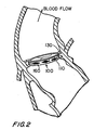
- FIG. 2 shows valve 100 after it has been deployed.
- Band 110 may be formed from expandable metal -- i.e., metal that has been perforated and cut in such a way that it can be expanded in one or more directions by deforming the metal in the vicinity of the cuts and perforations. This type of structure is frequently found in stents used to prevent collapses of tubular body structures; and band 110 could be a converted stent, possibly with some modifications.
- band 110 may be constructed from an expandable open mesh framework ( see mesh 360 in FIG. 3 and 4) -- e.g., a braid of nitinol, stainless steel, tungsten wires or polymer strands -- which may be covered with a rubber-like web -- e.g., of silicone --.
- the diameter of band 110 has increased, while the length of band 110 has decreased.
- the barbed heads of axially opposite fingers 130 converge, engage the tissue annulus, and secure valve 100 to the tissue annulus.
- the broadening and shortening of the black diamonds 160 shown in FIGS. 1 and 2 indicate the circumferential expansion and the lengthwise contraction of the metal.
- fingers 130 grab the tissue annulus and exert a force joining band 110 to the tissue annulus.
- the force exerted by the fingers on the tissue annulus forms a substantially leak-proof compression seal between band 110 and the tissue annulus.
- the tissue preferably forms a lip which abuts the valve portion 120 of valve 110.
- the outer walls of band 110 may include a gasket-like material.
- a separate gasket 150 (shown in FIG. 1) may be attached around band 110.
- the gasket-like material, or gasket 150 preferably conforms to the existing tissue annulus and seals the new valve to the tissue annulus to protect against leakage around, or through, band 110.
- Gasket 150 may preferably be formed from a soft, deformable biocompatible material -- e.g., polyurethane, silicone, dacron or other suitable material -- that readily conforms to existing tissue, yet provides a fluid-tight seal around valve 110.
- FIG. 3 shows another embodiment of an artificial heart valve 300 according to the principles of the invention.
- Valve 300 includes fingers 330 that are substantially perpendicular to the length of band 310.
- FIG. 4 shows valve 300 after it has been deployed. Fingers 330 are shown secured to the tissue annulus by the barbed heads of fingers 330 and a compression seal is preferably formed between band 310 and the tissue annulus.
- FIG. 5 shows one embodiment of an band 510 suitable for deployment to attach to the tissue annulus as shown in FIGS. 3 and 4.
- fingers 530 are parallel to the length of band 510.
- fingers 530 may be redirected radially outward, perpendicular to the length of band 510 by some suitable means. After redirection, fingers 530 may preferably appear similar to fingers 330 shown in FIGS. 3 and 4.
- band 510 can be further expanded such that fingers 530 engage, and are secured to, the tissue annulus.
- the band can be positioned using suture threads or other suitable devices which can be attached to rings 550. Rings 550 may be linked to the infrastructure of fingers 530.
- Band 510 should preferably be expandable. Fingers 530 can be oriented outward before expansion -- e.g., during production of band 510. Then, band 530 is positioned within the tissue annulus. Thereafter, fingers 530 are secured to the tissue annulus upon expansion of band 510.
- a connector band can also be deployed separate from a valve.
- a band such as band 510
- the band may first be expanded and secured to the tissue annulus at the required implant site. Then, the valve can be incorporated into the band.
- the band may contain a number of holes or recesses adapted to receive screws from an implanted valve, or seats for rivets or clips which are used to secure the valve to the previously deployed band. Alternatively, rivets which require no-preformed seats, but are popped through a flat portion of the band may also be used to secure the valve to the band. Examples of recesses 350, 450 are shown in FIGS. 3 and 4. The recesses may preferably be located on the interior side of the band.
- FIG. 6 shows an exemplary valve 600 deployed in a left ventricle outflow valve of a complete heart.
- Valve 600 has fingers 630 similar to the valve shown in FIGS. 3 and 4.
- Balloon 640 is shown as exiting from a guide catheter 660, as is known in the art.
- One way to guide balloon 640 is by markers 650 which are implemented on balloon 640, as is known in the art. Markers 650 allow the balloon to be positioned using x-rays or fluoroscopically. Once a desired position for balloon 640 is achieved, balloon 640 is expanded, and valve 600 is secured to the tissue annulus. In one embodiment, the old valve may not require removal, but may just be compressed out of the way by expanding the new valve.
- FIG. 7 shows an embodiment of a non-expanding valve 700 according to the principles of the invention.
- Valve 700 preferably includes fingers 730 that are oriented in a direction that is substantially parallel to the length of band 710 and are oriented in the direction of the blood flow. The exact orientation of the fingers can be configured before insertion.
- the surrounding tissue can be pulled up and over each retention finger. The tissue can be manipulated using a tweezers or other suitable tool.
- the fingers described throughout this application are preferably formed from an elastic material -- e.g., nitinol.
- the elasticity of the material allows the fingers to be expanded without undesirable deformation.
- the fingers may be heat-set to be flat against the length of band 710, or to be slightly projecting out from band 710.
- each flat individual finger 730 may be temporarily erected simultaneous to the tissue from the tissue annulus being pulled up and over the erected fingers. Thereafter, fingers 730 are released. When released, fingers 730 snap back to their original position, compressing and securing the tissue annulus to valve 700.
- retention fingers 730 may preferably be formed from relatively non-elastic, preferably annealed, stainless steel. Each finger is erected before deployment. Then, once the tissue annulus is pulled up and over each finger 730 such that the tissue annulus is pierced by each finger 730, the finger is crimped down against the valve body to secure the tissue annulus to valve 700.
- FIG. 8 shows valve 700 after it has been deployed within the tissue annulus.
- fingers 730 secure valve 700 to the tissue annulus.
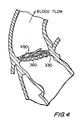
- FIGS. 9 and 10 show a valve 900 with fingers 930 oriented in a direction that is parallel to the length of band 710 but, unlike valve 700, is substantially opposite to the blood flow.
- fingers 930 are oriented in the direction of insertion which, in the case of the left ventricle outflow valve, is opposite the blood flow.
- the orientation of fingers 930 allows the surgeon to more readily advance the valve into the tissue annulus and to engage and secure the valve to the annulus.
- Another advantage of valve 900 is that the deployment of valve 900 does not require a tool to pull the flesh of the tissue annulus over the finger heads. Rather, valve 900 can be directly engaged to the tissue annulus by applying pressure to valve 900 opposite the direction of the blood flow.
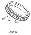
- FIG. 11 shows an embodiment of a preferably non-expandable connector band 1110 for use in the valves shown in FIGURES 7-10.
- band 1110 When band 1110 is inserted into the tissue annulus. Fingers 1130 and arches 1140 are caused to project outwards from band 1110. Fingers 1130 may be caused to project outwards when they are formed in the production process.
- the band When the band is expandable, it may be positioned within the tissue annulus, and, thereafter, the fingers are secured to the tissue annulus upon expansion of the band.
- FIG. 12 shows yet another embodiment of a valve 1210 according to the present invention.
- fingers 1230 are oriented in a circumferential direction around the circumference of valve 1210.
- Valve 1210 operates as follows: first, valve 1210 is positioned in the tissue annulus. This can be done by rotating valve 1210 into position (in the exemplary valve shown in FIG. 12, this requires a clockwise rotation around central longitudinal axis 1270) so fingers 1230 do not engage the tissue annulus. Then, valve 1210 is rotated in a counterclockwise direction around central longitudinal axis 1270. This rotation causes fingers 1230 to pierce the tissue annulus. Thereafter, fingers 1230 return to their original position (or, in the case of stainless steel fingers, the fingers are mechanically crimped to return to their original position) and the valve 1210 is secured to the tissue annulus. Rotation of valve 1210 can be accomplished using a tool which may be designed to rotate valve 1210 or with another suitable technique.
- FIG. 13 shows an end view of valve 1210. In this view, fingers 1230 are shown in a substantially fully expanded state.
- FIG. 14 shows another alternative embodiment of the invention wherein the fingers 1430 are preferably placed on the heart valve 1410 directly, without the interface of the connector band.
- the fingers are distributed circumferentially around the heart valve, and the heart valve is inserted directly into the tissue annulus.
- Fingers 1430 may preferably be attached to heart valve 1410 in any of the possible configurations described herein.
- fingers 1430 are shown as hooked and barbed, they may be either hooked or barbed. As mentioned above, this feature of hooked and/or barbed fingers may preferably be used in each embodiment of the invention.
- Each of the artificial heart valve attachment apparatus described herein preferably allows a replacement valve according to the invention to be implanted surgically or percutaneously.
- the diameter of an exemplary expandable valve and/or connector band is preferably between 3 and 5 millimeters before expansion. After expansion, the diameter of the valve and/or band is preferably between 15 and 20 millimeters.
- the length of the valve and/or band is preferably between .75 and 2 inches before expansion, and, after expansion, is preferably between .5 and 1.5 inches.
- Materials that are suitable for use in a connector band according to the invention and as described herein, preferably include stainless steel or tantalum. These materials are relatively easily yieldable under balloon pressure when constructed as described above with either a bio-compatible mesh or with perforations, and are substantially radiopaque.
- the preferably substantially uni-directional valve element itself is flexible, preferably porcine, tissue (the valve element may allow for a minimal backflow of fluid upon the change in direction of fluid flow).
- the valve in the embodiment described above in which the connector band is deployed separate from the valve is preferably a rigid valve formed from a suitable bio-compatible material -- e.g., stainless steel -- which may provide improved connectability with the connector band.
- the number of fingers required may preferably be between 10 and 40 barbed or hooked fingers around the circumference of the valve, and most preferably 24 fingers.
- the fingers may be formed from a variety of substances, including, but not limited to, nitinol or stainless steel.
Abstract
Description
- This invention relates to apparatus and methods for attaching replacement heart valves.
- The replacement of a defective heart valve requires an open heart procedure in which the old, defective, valve is removed and replaced with an artificial valve. Gerierally, this procedure requires the heart to be placed on a cardiopulmonary bypass (CPB) to allow the heart to be stopped and the new valve to be carefully sewn in place.
- This method of valve attachment, commonly known as suturing, is an effective method of attaching the new heart valve to the heart. However, it requires significant time and skill to complete. Therefore, extended CPB time is required. The extended CPB time associated with suturing, in conjunction with the complex nature of the procedure itself, may increase the likelihood of complications, including stroke, heart block and long patient recovery times.
- Therefore, it would be desirable to provide heart valve attachment apparatus and methods that significantly reduce attachment times.
- The above and other objects and advantages of the invention will be apparent upon consideration of the following detailed description, taken in conjunction with the accompanying drawings, in which like reference characters refer to like parts throughout:
- FIG. 1 is an elevational view of a preferred embodiment of a heart valve according to the invention.
- FIG. 2 is an elevational view of the heart valve of FIG. 1 in a deployed position.
- FIG. 3 is an elevational view of another embodiment of a heart valve according to the invention.
- FIG. 4 is an elevational view of the heart valve of FIG. 3 in a deployed position.
- FIG. 5 is an elevational view of a connector band according to the invention.
- FIG. 6 is an elevational view of the heart valve of FIGS. 3 and 4 in a deployed position.
- FIG. 7 is an elevational view of another embodiment of a heart valve according to the invention.
- FIG. 8 is an elevational view of the heart valve of FIG. 7 in a deployed position.
- FIG. 9 is an elevational view of another embodiment of a heart valve according to the invention.
- FIG. 10 is an elevational view of the heart valve of FIG. 9 in a deployed position.
- FIG. 11 is an elevational view of another connector band according to the invention.
- FIG. 12 is an elevational view of another connector band according to the invention.
- FIG. 13 is a top view of the connector band in FIG. 12.
- FIG. 14 is an elevational view of another embodiment of a heart valve according to the invention.
-
- It is an object of the invention to provide heart valve attachment apparatus and methods that significantly reduce attachment times.
- A valve apparatus for deploying in, and securing to, a tissue annulus, includes: a uni-directional valve portion for passing fluid in one direction and obstructing fluid in an opposite direction, a connector band located circumferentially around, and attached to, the valve portion and a plurality of fingers located circumferentially around, and attached to, the band. The fingers are adapted to secure the valve to the tissue annulus.
- In an alternative embodiment, a connector band can be deployed separate from the valve portion. After the band is deployed, a valve can be attached to the band by screws, pop rivets or other suitable attachment device or method.
- In another alternative embodiment, fingers can be implemented on the valve portion itself, thereby obviating the need for a connector band.
- This invention relates to heart valves which are modified so that the valve can be attached to the heart without the need for suturing. Significant technology has been developed related to replacing sutures in bypass grafting -- i.e., attaching a tissue conduit to another with a mechanical connector rather than sewing the conduits to each other to form the anastamosis. Examples of such technology are found in commonly assigned United States Patent No. 5,976,178 and co-pending commonly assigned patent applications 08/839,199, 08/946,742, 09/016,721, 09/187,335, 09/187,361 and 09/186,774, all of which are incorporated by reference herein in their entireties.
- These references, at least in part, disclose inventions related to methods and apparatus for attaching synthetic or biological tissue grafts without the need for sutures. Portions of the references deal specifically with methods and apparatus for attaching synthetic or biological tissue grafts to a connector, which is then secured to a blood vessel -- e.g., the aorta -- by using hooked or barbed fingers. In certain embodiments, the fingers are formed from an elastic material -- e.g., nitinol wire. In these embodiments, the fingers may be stretched or otherwise manipulated to pierce the tissue graft and retain the tissue graft with the hooked or barbed ends of the fingers. The elasticity of the fingers then causes the fingers to snap back such that the tissue graft is secured to the connector. The connector is then connected to a blood vessel to complete an anastamosis.
- Alternatively, the fingers may be formed from relatively non-elastic stainless steel. In these embodiments, the fingers are deformed to properly engage the tissue graft and then mechanically crimped to seal the connector to the tissue graft.
- The present invention provides methods and apparatus for using retention fingers, such as the fingers described above, to attach heart valves to hearts.
- FIG. 1 shows an
artificial heart valve 100 having a balloonexpandable connector band 110 with a one-way valve portion 120 integrated withinconnector band 110. Valve 100 is positioned for deployment in the left ventricle outflow valve of a heart (this location illustrates only one possible exemplary embodiment of the invention; and is not intended to limit the invention to use only in the left ventricle outflow valve.)Connector band 110 preferably includes a series ofretention fingers 130 with barbed ends -- i.e., the ends of the fingers have small projections that secure the fingers to their surface of engagement -- or, alternatively, hooked ends -- i.e., the ends of the fingers are bent --, or a combination of the two, spaced substantially circumferentially aroundband 110. Each finger preferably is attached adjacent to one end of the length ofband 110 and has a corresponding finger that opposes it and is attached to the other end of the length ofband 110. Thus, when the length ofband 110 is reduced, the ends of each set ofcorresponding fingers 130 converge and engage the surrounding tissue. - The invention operates as follows: first,
valve 100 is positioned for securing to the tissue annulus that surrounded the old valve. Then,balloon 140 is preferably positioned through the orifice ofvalve 100.Balloon 140 is then expanded. The positioning and expansion ofballoon 140 can be accomplished by methods that are known to those in the art and explained in more detail in the references which are incorporated by reference above -- e.g., U.S. Patent No. 5,976,178. - Expansion of
balloon 140 increases the circumference ofband 110 to conform to, and substantially fill, the tissue annulus. Asconnector band 110 expands circumferentially, it shortens in length -- i.e., the dimension ofband 110 that is substantially parallel to the blood flow. The shortening in length causes the barbed heads on each corresponding pair ofretention fingers 130 to converge and engage the surrounding tissue annulus, thereby securingvalve 100 to the tissue annulus. When the heads offingers 130 engage the tissue annulus, they preferably remain there permanently.Valve 120, which may preferably be formed from porcine tissue, or other suitable natural or synthetic tissue, can be pushed out of the way during expansion and then naturally returns following expansion. - FIG. 2 shows
valve 100 after it has been deployed.Band 110 may be formed from expandable metal -- i.e., metal that has been perforated and cut in such a way that it can be expanded in one or more directions by deforming the metal in the vicinity of the cuts and perforations. This type of structure is frequently found in stents used to prevent collapses of tubular body structures; andband 110 could be a converted stent, possibly with some modifications. Alternatively,band 110 may be constructed from an expandable open mesh framework (seemesh 360 in FIG. 3 and 4) -- e.g., a braid of nitinol, stainless steel, tungsten wires or polymer strands -- which may be covered with a rubber-like web -- e.g., of silicone --. - It should be noted that, following expansion of
band 110, the diameter ofband 110 has increased, while the length ofband 110 has decreased. As the length ofband 110 is decreased, the barbed heads of axiallyopposite fingers 130 converge, engage the tissue annulus, andsecure valve 100 to the tissue annulus. The broadening and shortening of theblack diamonds 160 shown in FIGS. 1 and 2 indicate the circumferential expansion and the lengthwise contraction of the metal. Following deployment,fingers 130 grab the tissue annulus and exert aforce joining band 110 to the tissue annulus. The force exerted by the fingers on the tissue annulus forms a substantially leak-proof compression seal betweenband 110 and the tissue annulus. Thus, the tissue preferably forms a lip which abuts thevalve portion 120 ofvalve 110. - The outer walls of
band 110 may include a gasket-like material. In an alternative embodiment, a separate gasket 150 (shown in FIG. 1) may be attached aroundband 110. To further enhance the seal betweenband 110 andvalve portion 120 the gasket-like material, orgasket 150, preferably conforms to the existing tissue annulus and seals the new valve to the tissue annulus to protect against leakage around, or through,band 110.Gasket 150 may preferably be formed from a soft, deformable biocompatible material -- e.g., polyurethane, silicone, dacron or other suitable material -- that readily conforms to existing tissue, yet provides a fluid-tight seal aroundvalve 110. - FIG. 3 shows another embodiment of an
artificial heart valve 300 according to the principles of the invention.Valve 300 includesfingers 330 that are substantially perpendicular to the length ofband 310. - FIG. 4 shows
valve 300 after it has been deployed.Fingers 330 are shown secured to the tissue annulus by the barbed heads offingers 330 and a compression seal is preferably formed betweenband 310 and the tissue annulus. - FIG. 5 shows one embodiment of an
band 510 suitable for deployment to attach to the tissue annulus as shown in FIGS. 3 and 4. At this stage,fingers 530 are parallel to the length ofband 510. However,fingers 530 may be redirected radially outward, perpendicular to the length ofband 510 by some suitable means. After redirection,fingers 530 may preferably appear similar tofingers 330 shown in FIGS. 3 and 4. Thereafter,band 510 can be further expanded such thatfingers 530 engage, and are secured to, the tissue annulus. - One advantage of the embodiment shown in FIG. 5 is that the band can be positioned using suture threads or other suitable devices which can be attached to
rings 550.Rings 550 may be linked to the infrastructure offingers 530. - Band 510 should preferably be expandable.
Fingers 530 can be oriented outward before expansion -- e.g., during production ofband 510. Then,band 530 is positioned within the tissue annulus. Thereafter,fingers 530 are secured to the tissue annulus upon expansion ofband 510. - In an alternative embodiment of the invention, a connector band can also be deployed separate from a valve. In this embodiment, a band, such as
band 510, may first be expanded and secured to the tissue annulus at the required implant site. Then, the valve can be incorporated into the band. To facilitate the connection of the band to the valve, the band may contain a number of holes or recesses adapted to receive screws from an implanted valve, or seats for rivets or clips which are used to secure the valve to the previously deployed band. Alternatively, rivets which require no-preformed seats, but are popped through a flat portion of the band may also be used to secure the valve to the band. Examples ofrecesses 350, 450 are shown in FIGS. 3 and 4. The recesses may preferably be located on the interior side of the band. - FIG. 6 shows an
exemplary valve 600 deployed in a left ventricle outflow valve of a complete heart.Valve 600 hasfingers 630 similar to the valve shown in FIGS. 3 and 4.Balloon 640 is shown as exiting from aguide catheter 660, as is known in the art. One way to guideballoon 640 is bymarkers 650 which are implemented onballoon 640, as is known in the art.Markers 650 allow the balloon to be positioned using x-rays or fluoroscopically. Once a desired position forballoon 640 is achieved,balloon 640 is expanded, andvalve 600 is secured to the tissue annulus. In one embodiment, the old valve may not require removal, but may just be compressed out of the way by expanding the new valve. - FIG. 7 shows an embodiment of a
non-expanding valve 700 according to the principles of the invention.Valve 700 preferably includesfingers 730 that are oriented in a direction that is substantially parallel to the length ofband 710 and are oriented in the direction of the blood flow. The exact orientation of the fingers can be configured before insertion. In this embodiment, oncevalve 700 is positioned within the tissue annulus, the surrounding tissue can be pulled up and over each retention finger. The tissue can be manipulated using a tweezers or other suitable tool. - The fingers described throughout this application are preferably formed from an elastic material -- e.g., nitinol. The elasticity of the material allows the fingers to be expanded without undesirable deformation. The fingers may be heat-set to be flat against the length of
band 710, or to be slightly projecting out fromband 710. During deployment through expansion offingers 730, each flatindividual finger 730 may be temporarily erected simultaneous to the tissue from the tissue annulus being pulled up and over the erected fingers. Thereafter,fingers 730 are released. When released,fingers 730 snap back to their original position, compressing and securing the tissue annulus tovalve 700. - In an alternative embodiment of
valve 700,retention fingers 730 may preferably be formed from relatively non-elastic, preferably annealed, stainless steel. Each finger is erected before deployment. Then, once the tissue annulus is pulled up and over eachfinger 730 such that the tissue annulus is pierced by eachfinger 730, the finger is crimped down against the valve body to secure the tissue annulus tovalve 700. - FIG. 8 shows
valve 700 after it has been deployed within the tissue annulus. In FIG. 8,fingers 730secure valve 700 to the tissue annulus. - FIGS. 9 and 10 show a
valve 900 withfingers 930 oriented in a direction that is parallel to the length ofband 710 but, unlikevalve 700, is substantially opposite to the blood flow. One advantage of this embodiment is thatfingers 930 are oriented in the direction of insertion which, in the case of the left ventricle outflow valve, is opposite the blood flow. Thus, the orientation offingers 930 allows the surgeon to more readily advance the valve into the tissue annulus and to engage and secure the valve to the annulus. Another advantage ofvalve 900 is that the deployment ofvalve 900 does not require a tool to pull the flesh of the tissue annulus over the finger heads. Rather,valve 900 can be directly engaged to the tissue annulus by applying pressure tovalve 900 opposite the direction of the blood flow. - FIG. 11 shows an embodiment of a preferably
non-expandable connector band 1110 for use in the valves shown in FIGURES 7-10. Whenband 1110 is inserted into the tissue annulus.Fingers 1130 and arches 1140 are caused to project outwards fromband 1110.Fingers 1130 may be caused to project outwards when they are formed in the production process. When the band is expandable, it may be positioned within the tissue annulus, and, thereafter, the fingers are secured to the tissue annulus upon expansion of the band. - FIG. 12 shows yet another embodiment of a
valve 1210 according to the present invention. Invalve 1210,fingers 1230 are oriented in a circumferential direction around the circumference ofvalve 1210. -
Valve 1210 operates as follows: first,valve 1210 is positioned in the tissue annulus. This can be done by rotatingvalve 1210 into position (in the exemplary valve shown in FIG. 12, this requires a clockwise rotation around central longitudinal axis 1270) sofingers 1230 do not engage the tissue annulus. Then,valve 1210 is rotated in a counterclockwise direction around centrallongitudinal axis 1270. This rotation causesfingers 1230 to pierce the tissue annulus. Thereafter,fingers 1230 return to their original position (or, in the case of stainless steel fingers, the fingers are mechanically crimped to return to their original position) and thevalve 1210 is secured to the tissue annulus. Rotation ofvalve 1210 can be accomplished using a tool which may be designed to rotatevalve 1210 or with another suitable technique. - FIG. 13 shows an end view of
valve 1210. In this view,fingers 1230 are shown in a substantially fully expanded state. - FIG. 14 shows another alternative embodiment of the invention wherein the
fingers 1430 are preferably placed on theheart valve 1410 directly, without the interface of the connector band. In this embodiment, the fingers are distributed circumferentially around the heart valve, and the heart valve is inserted directly into the tissue annulus.Fingers 1430 may preferably be attached toheart valve 1410 in any of the possible configurations described herein. - In addition, though
fingers 1430 are shown as hooked and barbed, they may be either hooked or barbed. As mentioned above, this feature of hooked and/or barbed fingers may preferably be used in each embodiment of the invention. - Each of the artificial heart valve attachment apparatus described herein preferably allows a replacement valve according to the invention to be implanted surgically or percutaneously.
- The diameter of an exemplary expandable valve and/or connector band, like the valves and bands described herein in accordance with the present invention, is preferably between 3 and 5 millimeters before expansion. After expansion, the diameter of the valve and/or band is preferably between 15 and 20 millimeters. The length of the valve and/or band is preferably between .75 and 2 inches before expansion, and, after expansion, is preferably between .5 and 1.5 inches.
- Materials that are suitable for use in a connector band according to the invention and as described herein, preferably include stainless steel or tantalum. These materials are relatively easily yieldable under balloon pressure when constructed as described above with either a bio-compatible mesh or with perforations, and are substantially radiopaque. The preferably substantially uni-directional valve element itself is flexible, preferably porcine, tissue (the valve element may allow for a minimal backflow of fluid upon the change in direction of fluid flow). The valve in the embodiment described above in which the connector band is deployed separate from the valve, is preferably a rigid valve formed from a suitable bio-compatible material -- e.g., stainless steel -- which may provide improved connectability with the connector band.
- In addition, for the embodiments of the invention described herein, the number of fingers required may preferably be between 10 and 40 barbed or hooked fingers around the circumference of the valve, and most preferably 24 fingers. As mentioned above, the fingers may be formed from a variety of substances, including, but not limited to, nitinol or stainless steel.
- Thus, an artificial heart valve attachment apparatus and methods that significantly reduce attachment times is provided. Persons skilled in the art will appreciate that the present invention can be practiced by other than the described embodiments, which are presented for purposes of illustration rather than of limitation, and the present invention is limited only by the claims which follow.
Claims (9)
- A valve apparatus for deploying in, and securing to, a tissue annulus, said valve comprising:a uni-directional valve portion for passing fluid in one direction and obstructing fluid in an opposite direction; anda plurality of fingers located circumferentially around, and attached to said valve, said fingers being adapted to secure said valve to said tissue annulus.
- The valve of claim 1, wherein said fingers are adapted to secure said valve to said tissue annulus upon deployment of said valve.
- The valve of claim 1 or 2, wherein said fingers can be expanded from a first position adjacent to said valve, engaged to said tissue annulus, and returned to said first position following said engagement, thereby securing said valve to said tissue annulus.
- The valve of claim 1, 2 or 3, wherein said fingers are formed from an elastic material.
- The valve of claim 1, 2, 3 or 4, wherein said valve comprises a gasket located around an outer circumference of said valve, said gasket for sealing between said valve and said tissue annulus.
- The valve of any one of claims 1 to 5, wherein said fingers are hooked and/or barbed.
- The valve of any one of claims 1 to 6, wherein at least a portion of each finger is oriented substantially parallel to the direction of fluid flow.
- The valve of any one of claims 1 to 7, wherein said fingers are substantially parallel to a central longitudinal axis of said valve.
- The valve of any one of claims 1 to 7, wherein said fingers are substantially perpendicular to a central longitudinal axis of said valve.
Applications Claiming Priority (3)
| Application Number | Priority Date | Filing Date | Title |
|---|---|---|---|
| US13075899P | 1999-04-23 | 1999-04-23 | |
| US130758P | 1999-04-23 | ||
| EP00922203A EP1171059B1 (en) | 1999-04-23 | 2000-04-14 | Artificial heart valve attachment apparatus |
Related Parent Applications (1)
| Application Number | Title | Priority Date | Filing Date |
|---|---|---|---|
| EP00922203A Division EP1171059B1 (en) | 1999-04-23 | 2000-04-14 | Artificial heart valve attachment apparatus |
Publications (2)
| Publication Number | Publication Date |
|---|---|
| EP1584307A2 true EP1584307A2 (en) | 2005-10-12 |
| EP1584307A3 EP1584307A3 (en) | 2005-10-19 |
Family
ID=22446182
Family Applications (2)
| Application Number | Title | Priority Date | Filing Date |
|---|---|---|---|
| EP00922203A Expired - Lifetime EP1171059B1 (en) | 1999-04-23 | 2000-04-14 | Artificial heart valve attachment apparatus |
| EP05010329A Withdrawn EP1584307A3 (en) | 1999-04-23 | 2000-04-14 | Artificial heart valve with attachment fingers |
Family Applications Before (1)
| Application Number | Title | Priority Date | Filing Date |
|---|---|---|---|
| EP00922203A Expired - Lifetime EP1171059B1 (en) | 1999-04-23 | 2000-04-14 | Artificial heart valve attachment apparatus |
Country Status (6)
| Country | Link |
|---|---|
| US (1) | US7569072B2 (en) |
| EP (2) | EP1171059B1 (en) |
| AT (1) | ATE308288T1 (en) |
| AU (1) | AU4242800A (en) |
| DE (1) | DE60023676T2 (en) |
| WO (1) | WO2000064380A1 (en) |
Families Citing this family (141)
| Publication number | Priority date | Publication date | Assignee | Title |
|---|---|---|---|---|
| US8366769B2 (en) | 2000-06-01 | 2013-02-05 | Edwards Lifesciences Corporation | Low-profile, pivotable heart valve sewing ring |
| US6409758B2 (en) | 2000-07-27 | 2002-06-25 | Edwards Lifesciences Corporation | Heart valve holder for constricting the valve commissures and methods of use |
| US7381220B2 (en) * | 2000-09-20 | 2008-06-03 | Ample Medical, Inc. | Devices, systems, and methods for supplementing, repairing, or replacing a native heart valve leaflet |
| US6602286B1 (en) | 2000-10-26 | 2003-08-05 | Ernst Peter Strecker | Implantable valve system |
| US6893460B2 (en) | 2001-10-11 | 2005-05-17 | Percutaneous Valve Technologies Inc. | Implantable prosthetic valve |
| US7201771B2 (en) | 2001-12-27 | 2007-04-10 | Arbor Surgical Technologies, Inc. | Bioprosthetic heart valve |
| US6752828B2 (en) | 2002-04-03 | 2004-06-22 | Scimed Life Systems, Inc. | Artificial valve |
| US7959674B2 (en) | 2002-07-16 | 2011-06-14 | Medtronic, Inc. | Suture locking assembly and method of use |
| US8551162B2 (en) | 2002-12-20 | 2013-10-08 | Medtronic, Inc. | Biologically implantable prosthesis |
| US6945957B2 (en) | 2002-12-30 | 2005-09-20 | Scimed Life Systems, Inc. | Valve treatment catheter and methods |
| EP1631218B1 (en) * | 2003-05-28 | 2010-09-15 | Cook Incorporated | Prosthetic valve with vessel engaging member |
| US8021421B2 (en) | 2003-08-22 | 2011-09-20 | Medtronic, Inc. | Prosthesis heart valve fixturing device |
| US7556647B2 (en) | 2003-10-08 | 2009-07-07 | Arbor Surgical Technologies, Inc. | Attachment device and methods of using the same |
| US8128681B2 (en) | 2003-12-19 | 2012-03-06 | Boston Scientific Scimed, Inc. | Venous valve apparatus, system, and method |
| US7854761B2 (en) | 2003-12-19 | 2010-12-21 | Boston Scientific Scimed, Inc. | Methods for venous valve replacement with a catheter |
| US7871435B2 (en) | 2004-01-23 | 2011-01-18 | Edwards Lifesciences Corporation | Anatomically approximate prosthetic mitral heart valve |
| US7276078B2 (en) * | 2004-06-30 | 2007-10-02 | Edwards Lifesciences Pvt | Paravalvular leak detection, sealing, and prevention |
| US7566343B2 (en) | 2004-09-02 | 2009-07-28 | Boston Scientific Scimed, Inc. | Cardiac valve, system, and method |
| AU2004324043A1 (en) | 2004-10-02 | 2006-04-20 | Christoph Hans Huber | Methods and devices for repair or replacement of heart valves or adjacent tissue without the need for full cardiopulmonary support |
| US20080015671A1 (en) * | 2004-11-19 | 2008-01-17 | Philipp Bonhoeffer | Method And Apparatus For Treatment Of Cardiac Valves |
| US7854755B2 (en) | 2005-02-01 | 2010-12-21 | Boston Scientific Scimed, Inc. | Vascular catheter, system, and method |
| US20060173490A1 (en) | 2005-02-01 | 2006-08-03 | Boston Scientific Scimed, Inc. | Filter system and method |
| US7670368B2 (en) | 2005-02-07 | 2010-03-02 | Boston Scientific Scimed, Inc. | Venous valve apparatus, system, and method |
| US7780722B2 (en) | 2005-02-07 | 2010-08-24 | Boston Scientific Scimed, Inc. | Venous valve apparatus, system, and method |
| US8574257B2 (en) | 2005-02-10 | 2013-11-05 | Edwards Lifesciences Corporation | System, device, and method for providing access in a cardiovascular environment |
| US7867274B2 (en) | 2005-02-23 | 2011-01-11 | Boston Scientific Scimed, Inc. | Valve apparatus, system and method |
| US8083793B2 (en) | 2005-02-28 | 2011-12-27 | Medtronic, Inc. | Two piece heart valves including multiple lobe valves and methods for implanting them |
| US20060195186A1 (en) | 2005-02-28 | 2006-08-31 | Drews Michael J | Connectors for two piece heart valves and methods for implanting such heart valves |
| US7513909B2 (en) | 2005-04-08 | 2009-04-07 | Arbor Surgical Technologies, Inc. | Two-piece prosthetic valves with snap-in connection and methods for use |
| US7722666B2 (en) | 2005-04-15 | 2010-05-25 | Boston Scientific Scimed, Inc. | Valve apparatus, system and method |
| EP2901967B1 (en) | 2005-05-24 | 2019-10-02 | Edwards Lifesciences Corporation | Rapid deployment prosthetic heart valve |
| WO2006130505A2 (en) | 2005-05-27 | 2006-12-07 | Arbor Surgical Technologies, Inc. | Gasket with collar for prosthetic heart valves and methods for using them |
| US8012198B2 (en) | 2005-06-10 | 2011-09-06 | Boston Scientific Scimed, Inc. | Venous valve, system, and method |
| US7776084B2 (en) | 2005-07-13 | 2010-08-17 | Edwards Lifesciences Corporation | Prosthetic mitral heart valve having a contoured sewing ring |
| US20070027533A1 (en) * | 2005-07-28 | 2007-02-01 | Medtronic Vascular, Inc. | Cardiac valve annulus restraining device |
| US7569071B2 (en) | 2005-09-21 | 2009-08-04 | Boston Scientific Scimed, Inc. | Venous valve, system, and method with sinus pocket |
| US8092520B2 (en) | 2005-11-10 | 2012-01-10 | CardiAQ Technologies, Inc. | Vascular prosthesis connecting stent |
| US7799038B2 (en) | 2006-01-20 | 2010-09-21 | Boston Scientific Scimed, Inc. | Translumenal apparatus, system, and method |
| US7967857B2 (en) | 2006-01-27 | 2011-06-28 | Medtronic, Inc. | Gasket with spring collar for prosthetic heart valves and methods for making and using them |
| WO2007130881A2 (en) | 2006-04-29 | 2007-11-15 | Arbor Surgical Technologies, Inc. | Multiple component prosthetic heart valve assemblies and apparatus and methods for delivering them |
| US8021161B2 (en) | 2006-05-01 | 2011-09-20 | Edwards Lifesciences Corporation | Simulated heart valve root for training and testing |
| WO2008013915A2 (en) | 2006-07-28 | 2008-01-31 | Arshad Quadri | Percutaneous valve prosthesis and system and method for implanting same |
| GB2440912B (en) * | 2006-08-14 | 2009-03-04 | Heartvalve Ltd | Surgical fastening device |
| US8133270B2 (en) | 2007-01-08 | 2012-03-13 | California Institute Of Technology | In-situ formation of a valve |
| US7967853B2 (en) | 2007-02-05 | 2011-06-28 | Boston Scientific Scimed, Inc. | Percutaneous valve, system and method |
| US8828079B2 (en) | 2007-07-26 | 2014-09-09 | Boston Scientific Scimed, Inc. | Circulatory valve, system and method |
| US7892276B2 (en) | 2007-12-21 | 2011-02-22 | Boston Scientific Scimed, Inc. | Valve with delayed leaflet deployment |
| EP2367505B1 (en) | 2008-09-29 | 2020-08-12 | Edwards Lifesciences CardiAQ LLC | Heart valve |
| US8449625B2 (en) | 2009-10-27 | 2013-05-28 | Edwards Lifesciences Corporation | Methods of measuring heart valve annuluses for valve replacement |
| CA2743719C (en) | 2008-11-25 | 2019-03-19 | Edwards Lifesciences Corporation | Apparatus and method for in situ expansion of prosthetic device |
| US8308798B2 (en) | 2008-12-19 | 2012-11-13 | Edwards Lifesciences Corporation | Quick-connect prosthetic heart valve and methods |
| US9980818B2 (en) | 2009-03-31 | 2018-05-29 | Edwards Lifesciences Corporation | Prosthetic heart valve system with positioning markers |
| CA2961053C (en) | 2009-04-15 | 2019-04-30 | Edwards Lifesciences Cardiaq Llc | Vascular implant and delivery system |
| US8348998B2 (en) | 2009-06-26 | 2013-01-08 | Edwards Lifesciences Corporation | Unitary quick connect prosthetic heart valve and deployment system and methods |
| US20110313515A1 (en) | 2010-06-21 | 2011-12-22 | Arshad Quadri | Replacement heart valve |
| US8579964B2 (en) | 2010-05-05 | 2013-11-12 | Neovasc Inc. | Transcatheter mitral valve prosthesis |
| CN102883684B (en) | 2010-05-10 | 2015-04-08 | 爱德华兹生命科学公司 | Prosthetic heart valve |
| US9554901B2 (en) | 2010-05-12 | 2017-01-31 | Edwards Lifesciences Corporation | Low gradient prosthetic heart valve |
| WO2012012660A2 (en) * | 2010-07-21 | 2012-01-26 | Accola Kevin D | Prosthetic heart valves and devices, systems, and methods for deploying prosthetic heart valves |
| US8518107B2 (en) | 2010-08-04 | 2013-08-27 | Valcare, Inc. | Percutaneous transcatheter repair of heart valves |
| US8641757B2 (en) | 2010-09-10 | 2014-02-04 | Edwards Lifesciences Corporation | Systems for rapidly deploying surgical heart valves |
| US9370418B2 (en) | 2010-09-10 | 2016-06-21 | Edwards Lifesciences Corporation | Rapidly deployable surgical heart valves |
| US9125741B2 (en) | 2010-09-10 | 2015-09-08 | Edwards Lifesciences Corporation | Systems and methods for ensuring safe and rapid deployment of prosthetic heart valves |
| WO2012040655A2 (en) | 2010-09-23 | 2012-03-29 | Cardiaq Valve Technologies, Inc. | Replacement heart valves, delivery devices and methods |
| US8845720B2 (en) | 2010-09-27 | 2014-09-30 | Edwards Lifesciences Corporation | Prosthetic heart valve frame with flexible commissures |
| WO2012136249A1 (en) * | 2011-04-05 | 2012-10-11 | Ethicon Endo-Surgery, Inc. | An endoluminal lining system and a method for endoluminally lining a hollow organ |
| US9554897B2 (en) | 2011-04-28 | 2017-01-31 | Neovasc Tiara Inc. | Methods and apparatus for engaging a valve prosthesis with tissue |
| US9308087B2 (en) | 2011-04-28 | 2016-04-12 | Neovasc Tiara Inc. | Sequentially deployed transcatheter mitral valve prosthesis |
| US8945209B2 (en) | 2011-05-20 | 2015-02-03 | Edwards Lifesciences Corporation | Encapsulated heart valve |
| US9402721B2 (en) | 2011-06-01 | 2016-08-02 | Valcare, Inc. | Percutaneous transcatheter repair of heart valves via trans-apical access |
| US9668859B2 (en) | 2011-08-05 | 2017-06-06 | California Institute Of Technology | Percutaneous heart valve delivery systems |
| US9078747B2 (en) | 2011-12-21 | 2015-07-14 | Edwards Lifesciences Corporation | Anchoring device for replacing or repairing a heart valve |
| US10940167B2 (en) | 2012-02-10 | 2021-03-09 | Cvdevices, Llc | Methods and uses of biological tissues for various stent and other medical applications |
| US9180008B2 (en) | 2012-02-29 | 2015-11-10 | Valcare, Inc. | Methods, devices, and systems for percutaneously anchoring annuloplasty rings |
| US9839519B2 (en) | 2012-02-29 | 2017-12-12 | Valcare, Inc. | Percutaneous annuloplasty system with anterior-posterior adjustment |
| US9427315B2 (en) | 2012-04-19 | 2016-08-30 | Caisson Interventional, LLC | Valve replacement systems and methods |
| US9011515B2 (en) | 2012-04-19 | 2015-04-21 | Caisson Interventional, LLC | Heart valve assembly systems and methods |
| US9345573B2 (en) | 2012-05-30 | 2016-05-24 | Neovasc Tiara Inc. | Methods and apparatus for loading a prosthesis onto a delivery system |
| AU2014214700B2 (en) | 2013-02-11 | 2018-01-18 | Cook Medical Technologies Llc | Expandable support frame and medical device |
| US20140277427A1 (en) | 2013-03-14 | 2014-09-18 | Cardiaq Valve Technologies, Inc. | Prosthesis for atraumatically grasping intralumenal tissue and methods of delivery |
| US9730791B2 (en) | 2013-03-14 | 2017-08-15 | Edwards Lifesciences Cardiaq Llc | Prosthesis for atraumatically grasping intralumenal tissue and methods of delivery |
| SG11201506352SA (en) | 2013-03-15 | 2015-09-29 | Edwards Lifesciences Corp | Valved aortic conduits |
| EP3804646A1 (en) | 2013-03-15 | 2021-04-14 | Valcare, Inc. | Systems for delivery of annuloplasty rings |
| US11007058B2 (en) | 2013-03-15 | 2021-05-18 | Edwards Lifesciences Corporation | Valved aortic conduits |
| WO2014144247A1 (en) | 2013-03-15 | 2014-09-18 | Arash Kheradvar | Handle mechanism and functionality for repositioning and retrieval of transcatheter heart valves |
| US9572665B2 (en) | 2013-04-04 | 2017-02-21 | Neovasc Tiara Inc. | Methods and apparatus for delivering a prosthetic valve to a beating heart |
| US10813751B2 (en) | 2013-05-22 | 2020-10-27 | Valcare, Inc. | Transcatheter prosthetic valve for mitral or tricuspid valve replacement |
| US20160120642A1 (en) | 2013-05-24 | 2016-05-05 | Valcare, Inc. | Heart and peripheral vascular valve replacement in conjunction with a support ring |
| US9468527B2 (en) | 2013-06-12 | 2016-10-18 | Edwards Lifesciences Corporation | Cardiac implant with integrated suture fasteners |
| EP3013253B1 (en) | 2013-06-28 | 2021-01-06 | ValCare, Inc. | Device for securing an article to a tissue |
| US9919137B2 (en) | 2013-08-28 | 2018-03-20 | Edwards Lifesciences Corporation | Integrated balloon catheter inflation system |
| US10195028B2 (en) | 2013-09-10 | 2019-02-05 | Edwards Lifesciences Corporation | Magnetic retaining mechanisms for prosthetic valves |
| SG11201508895RA (en) | 2013-09-20 | 2015-11-27 | Edwards Lifesciences Corp | Heart valves with increased effective orifice area |
| US9421094B2 (en) | 2013-10-23 | 2016-08-23 | Caisson Interventional, LLC | Methods and systems for heart valve therapy |
| US20150122687A1 (en) | 2013-11-06 | 2015-05-07 | Edwards Lifesciences Corporation | Bioprosthetic heart valves having adaptive seals to minimize paravalvular leakage |
| WO2015127283A1 (en) | 2014-02-21 | 2015-08-27 | Cardiaq Valve Technologies, Inc. | Delivery device for controlled deployement of a replacement valve |
| ES2711663T3 (en) * | 2014-03-18 | 2019-05-06 | Nvt Ag | Cardiac valve implant |
| US9549816B2 (en) | 2014-04-03 | 2017-01-24 | Edwards Lifesciences Corporation | Method for manufacturing high durability heart valve |
| US9585752B2 (en) | 2014-04-30 | 2017-03-07 | Edwards Lifesciences Corporation | Holder and deployment system for surgical heart valves |
| WO2015179423A1 (en) | 2014-05-19 | 2015-11-26 | Cardiaq Valve Technologies, Inc. | Replacement mitral valve with annular flap |
| US9974647B2 (en) | 2014-06-12 | 2018-05-22 | Caisson Interventional, LLC | Two stage anchor and mitral valve assembly |
| USD867594S1 (en) | 2015-06-19 | 2019-11-19 | Edwards Lifesciences Corporation | Prosthetic heart valve |
| CA2914094C (en) | 2014-06-20 | 2021-01-05 | Edwards Lifesciences Corporation | Surgical heart valves identifiable post-implant |
| US9750607B2 (en) | 2014-10-23 | 2017-09-05 | Caisson Interventional, LLC | Systems and methods for heart valve therapy |
| US9750605B2 (en) | 2014-10-23 | 2017-09-05 | Caisson Interventional, LLC | Systems and methods for heart valve therapy |
| US10376363B2 (en) | 2015-04-30 | 2019-08-13 | Edwards Lifesciences Cardiaq Llc | Replacement mitral valve, delivery system for replacement mitral valve and methods of use |
| CA2990872C (en) | 2015-06-22 | 2022-03-22 | Edwards Lifescience Cardiaq Llc | Actively controllable heart valve implant and methods of controlling same |
| US10092400B2 (en) | 2015-06-23 | 2018-10-09 | Edwards Lifesciences Cardiaq Llc | Systems and methods for anchoring and sealing a prosthetic heart valve |
| CR20170597A (en) | 2015-07-02 | 2018-04-20 | Edwards Lifesciences Corp | INTEGRATED HYBRID HEART VALVES |
| WO2017004369A1 (en) | 2015-07-02 | 2017-01-05 | Edwards Lifesciences Corporation | Hybrid heart valves adapted for post-implant expansion |
| US10117744B2 (en) | 2015-08-26 | 2018-11-06 | Edwards Lifesciences Cardiaq Llc | Replacement heart valves and methods of delivery |
| US10575951B2 (en) | 2015-08-26 | 2020-03-03 | Edwards Lifesciences Cardiaq Llc | Delivery device and methods of use for transapical delivery of replacement mitral valve |
| US10350066B2 (en) | 2015-08-28 | 2019-07-16 | Edwards Lifesciences Cardiaq Llc | Steerable delivery system for replacement mitral valve and methods of use |
| EP3344158B1 (en) | 2015-09-02 | 2023-03-01 | Edwards Lifesciences Corporation | Spacer for securing a transcatheter valve to a bioprosthetic cardiac structure |
| US10080653B2 (en) | 2015-09-10 | 2018-09-25 | Edwards Lifesciences Corporation | Limited expansion heart valve |
| EP3960127A1 (en) | 2015-12-30 | 2022-03-02 | Caisson Interventional, LLC | Systems and methods for heart valve therapy |
| US10433952B2 (en) | 2016-01-29 | 2019-10-08 | Neovasc Tiara Inc. | Prosthetic valve for avoiding obstruction of outflow |
| US10667904B2 (en) | 2016-03-08 | 2020-06-02 | Edwards Lifesciences Corporation | Valve implant with integrated sensor and transmitter |
| US10456245B2 (en) | 2016-05-16 | 2019-10-29 | Edwards Lifesciences Corporation | System and method for applying material to a stent |
| CN107753153B (en) | 2016-08-15 | 2022-05-31 | 沃卡尔有限公司 | Device and method for treating heart valve insufficiency |
| AU2017361296B2 (en) | 2016-11-21 | 2022-09-29 | Neovasc Tiara Inc. | Methods and systems for rapid retraction of a transcatheter heart valve delivery system |
| USD846122S1 (en) | 2016-12-16 | 2019-04-16 | Edwards Lifesciences Corporation | Heart valve sizer |
| US10905550B2 (en) | 2017-02-01 | 2021-02-02 | Medtronic Vascular, Inc. | Heart valve prostheses including torque anchoring mechanisms and delivery devices for the heart valve prostheses |
| CN108618871A (en) | 2017-03-17 | 2018-10-09 | 沃卡尔有限公司 | Bicuspid valve with multi-direction anchor portion or tricuspid valve repair system |
| US10463485B2 (en) | 2017-04-06 | 2019-11-05 | Edwards Lifesciences Corporation | Prosthetic valve holders with automatic deploying mechanisms |
| CA3060663C (en) | 2017-04-28 | 2024-03-26 | Edwards Lifesciences Corporation | Prosthetic heart valve with collapsible holder |
| CN110831547B (en) | 2017-06-21 | 2022-07-15 | 爱德华兹生命科学公司 | Double-wire limited expansion heart valve |
| US10813757B2 (en) | 2017-07-06 | 2020-10-27 | Edwards Lifesciences Corporation | Steerable rail delivery system |
| US10856984B2 (en) | 2017-08-25 | 2020-12-08 | Neovasc Tiara Inc. | Sequentially deployed transcatheter mitral valve prosthesis |
| CN111565678B (en) | 2018-01-23 | 2023-07-07 | 爱德华兹生命科学公司 | Prosthetic valve holders, systems, and methods |
| EP3720390A2 (en) | 2018-01-25 | 2020-10-14 | Edwards Lifesciences Corporation | Delivery system for aided replacement valve recapture and repositioning post- deployment |
| US11051934B2 (en) | 2018-02-28 | 2021-07-06 | Edwards Lifesciences Corporation | Prosthetic mitral valve with improved anchors and seal |
| USD908874S1 (en) | 2018-07-11 | 2021-01-26 | Edwards Lifesciences Corporation | Collapsible heart valve sizer |
| CA3118599A1 (en) | 2018-11-08 | 2020-05-14 | Neovasc Tiara Inc. | Ventricular deployment of a transcatheter mitral valve prosthesis |
| WO2020117842A1 (en) | 2018-12-03 | 2020-06-11 | Valcare, Inc. | Stabilizing and adjusting tool for controlling a minimally invasive mitral / tricuspid valve repair system |
| US11602429B2 (en) | 2019-04-01 | 2023-03-14 | Neovasc Tiara Inc. | Controllably deployable prosthetic valve |
| AU2020271896B2 (en) | 2019-04-10 | 2022-10-13 | Neovasc Tiara Inc. | Prosthetic valve with natural blood flow |
| EP3972673A4 (en) | 2019-05-20 | 2023-06-07 | Neovasc Tiara Inc. | Introducer with hemostasis mechanism |
| WO2020257643A1 (en) | 2019-06-20 | 2020-12-24 | Neovasc Tiara Inc. | Low profile prosthetic mitral valve |
| WO2021011702A1 (en) | 2019-07-15 | 2021-01-21 | Valcare, Inc. | Transcatheter bio-prosthesis member and support structure |
| WO2021126778A1 (en) | 2019-12-16 | 2021-06-24 | Edwards Lifesciences Corporation | Valve holder assembly with suture looping protection |
Citations (6)
| Publication number | Priority date | Publication date | Assignee | Title |
|---|---|---|---|---|
| US3143742A (en) * | 1963-03-19 | 1964-08-11 | Surgitool Inc | Prosthetic sutureless heart valve |
| US3526906A (en) * | 1965-11-05 | 1970-09-08 | Lorraine Carbone | Prosthetic implants made from carbonaceous materials |
| US3546710A (en) * | 1965-12-11 | 1970-12-15 | Valery Ivanovich Shumakov | Cardiac valve prosthesis for sutureless fixation |
| US3574865A (en) * | 1968-08-08 | 1971-04-13 | Michigan Instr Inc | Prosthetic sutureless heart valve |
| US3686740A (en) * | 1970-06-19 | 1972-08-29 | Donald P Shiley | Method of assemblying a sutureless heart valve |
| US5855601A (en) * | 1996-06-21 | 1999-01-05 | The Trustees Of Columbia University In The City Of New York | Artificial heart valve and method and device for implanting the same |
Family Cites Families (21)
| Publication number | Priority date | Publication date | Assignee | Title |
|---|---|---|---|---|
| US3464065A (en) | 1965-07-08 | 1969-09-02 | Surgitool Inc | Prosthetic heart valve |
| US5104399A (en) | 1986-12-10 | 1992-04-14 | Endovascular Technologies, Inc. | Artificial graft and implantation method |
| US5843170A (en) * | 1994-09-02 | 1998-12-01 | Ahn; Sam Seunghae | Apparatus and method for performing aneurysm repair |
| AU3783195A (en) | 1994-11-15 | 1996-05-23 | Advanced Cardiovascular Systems Inc. | Intraluminal stent for attaching a graft |
| US5824064A (en) * | 1995-05-05 | 1998-10-20 | Taheri; Syde A. | Technique for aortic valve replacement with simultaneous aortic arch graft insertion and apparatus therefor |
| WO1997010757A1 (en) * | 1995-09-22 | 1997-03-27 | Autogenics | Sewing ring with integral retaining springs |
| DE19605042A1 (en) * | 1996-02-12 | 1998-01-15 | Figulla Hans Reiner Prof Dr Me | Vessel implant for bridging vascular weaknesses |
| AU5102198A (en) | 1996-11-07 | 1998-05-29 | Vascular Science Inc. | Medical grafting connectors and fasteners |
| US5976178A (en) | 1996-11-07 | 1999-11-02 | Vascular Science Inc. | Medical grafting methods |
| US6036702A (en) | 1997-04-23 | 2000-03-14 | Vascular Science Inc. | Medical grafting connectors and fasteners |
| DE19731834A1 (en) * | 1997-07-24 | 1999-06-17 | Ernst Peter Prof Dr M Strecker | Implantation device |
| US6074416A (en) | 1997-10-09 | 2000-06-13 | St. Jude Medical Cardiovascular Group, Inc. | Wire connector structures for tubular grafts |
| US6254642B1 (en) * | 1997-12-09 | 2001-07-03 | Thomas V. Taylor | Perorally insertable gastroesophageal anti-reflux valve prosthesis and tool for implantation thereof |
| AU1923999A (en) | 1998-01-30 | 1999-08-16 | Vascular Science Inc. | Medical graft connector or plug structures, and methods of making and installingsame |
| US6059827A (en) * | 1998-05-04 | 2000-05-09 | Axya Medical, Inc. | Sutureless cardiac valve prosthesis, and devices and methods for implanting them |
| US6106550A (en) | 1998-07-10 | 2000-08-22 | Sulzer Carbomedics Inc. | Implantable attaching ring |
| US6197054B1 (en) | 1998-09-01 | 2001-03-06 | Sulzer Carbomedics Inc. | Sutureless cuff for heart valves |
| EP1126795A2 (en) | 1998-11-06 | 2001-08-29 | St. Jude Medical Cardiovascular Group, Inc. | Medical graft connector component and methods of making and installing same |
| US6152937A (en) | 1998-11-06 | 2000-11-28 | St. Jude Medical Cardiovascular Group, Inc. | Medical graft connector and methods of making and installing same |
| US6113612A (en) | 1998-11-06 | 2000-09-05 | St. Jude Medical Cardiovascular Group, Inc. | Medical anastomosis apparatus |
| US6241765B1 (en) | 1999-07-15 | 2001-06-05 | Sulzer Carbomedics Inc. | Stapled heart prosthesis and method of installing same |
-
2000
- 2000-04-14 WO PCT/US2000/010081 patent/WO2000064380A1/en active IP Right Grant
- 2000-04-14 EP EP00922203A patent/EP1171059B1/en not_active Expired - Lifetime
- 2000-04-14 AT AT00922203T patent/ATE308288T1/en active
- 2000-04-14 EP EP05010329A patent/EP1584307A3/en not_active Withdrawn
- 2000-04-14 AU AU42428/00A patent/AU4242800A/en not_active Abandoned
- 2000-04-14 DE DE60023676T patent/DE60023676T2/en not_active Expired - Lifetime
-
2005
- 2005-11-23 US US11/285,856 patent/US7569072B2/en not_active Expired - Fee Related
Patent Citations (6)
| Publication number | Priority date | Publication date | Assignee | Title |
|---|---|---|---|---|
| US3143742A (en) * | 1963-03-19 | 1964-08-11 | Surgitool Inc | Prosthetic sutureless heart valve |
| US3526906A (en) * | 1965-11-05 | 1970-09-08 | Lorraine Carbone | Prosthetic implants made from carbonaceous materials |
| US3546710A (en) * | 1965-12-11 | 1970-12-15 | Valery Ivanovich Shumakov | Cardiac valve prosthesis for sutureless fixation |
| US3574865A (en) * | 1968-08-08 | 1971-04-13 | Michigan Instr Inc | Prosthetic sutureless heart valve |
| US3686740A (en) * | 1970-06-19 | 1972-08-29 | Donald P Shiley | Method of assemblying a sutureless heart valve |
| US5855601A (en) * | 1996-06-21 | 1999-01-05 | The Trustees Of Columbia University In The City Of New York | Artificial heart valve and method and device for implanting the same |
Also Published As
| Publication number | Publication date |
|---|---|
| ATE308288T1 (en) | 2005-11-15 |
| WO2000064380A1 (en) | 2000-11-02 |
| EP1171059A1 (en) | 2002-01-16 |
| EP1584307A3 (en) | 2005-10-19 |
| EP1171059B1 (en) | 2005-11-02 |
| DE60023676T2 (en) | 2006-06-01 |
| DE60023676D1 (en) | 2005-12-08 |
| US20060136054A1 (en) | 2006-06-22 |
| US7569072B2 (en) | 2009-08-04 |
| WO2000064380A9 (en) | 2001-07-19 |
| AU4242800A (en) | 2000-11-10 |
Similar Documents
| Publication | Publication Date | Title |
|---|---|---|
| US7147663B1 (en) | Artificial heart valve attachment apparatus and methods | |
| US7569072B2 (en) | Artificial heart valve attachment apparatus and methods | |
| AU2020202927B2 (en) | Occluder and anastomosis devices | |
| US5972017A (en) | Method of installing tubular medical graft connectors | |
| US20220370071A1 (en) | Occluder and Anastomosis Devices | |
| US8808351B2 (en) | Stretchable prosthesis fenestration | |
| EP2720642B1 (en) | Heart valve prosthesis anchoring devices | |
| US6068654A (en) | T-shaped medical graft connector | |
| EP2193762A1 (en) | Prosthetic valve for intraluminal implantation | |
| US20020022891A1 (en) | Medical set for intervention on an anatomical duct, sealing ring pertaining to said set and use of said ring | |
| AU2019253802B2 (en) | Occluder and anastomosis devices | |
| US20110118651A1 (en) | Method and apparatus for effecting a percutaneous aortic valve bypass |
Legal Events
| Date | Code | Title | Description |
|---|---|---|---|
| PUAI | Public reference made under article 153(3) epc to a published international application that has entered the european phase |
Free format text: ORIGINAL CODE: 0009012 |
|
| PUAL | Search report despatched |
Free format text: ORIGINAL CODE: 0009013 |
|
| AC | Divisional application: reference to earlier application |
Ref document number: 1171059 Country of ref document: EP Kind code of ref document: P |
|
| AK | Designated contracting states |
Kind code of ref document: A2 Designated state(s): AT BE CH CY DE DK ES FI FR GB GR IE IT LI LU MC NL PT SE |
|
| AK | Designated contracting states |
Kind code of ref document: A3 Designated state(s): AT BE CH CY DE DK ES FI FR GB GR IE IT LI LU MC NL PT SE |
|
| RIN1 | Information on inventor provided before grant (corrected) |
Inventor name: SWANSON, WILLIAM J. Inventor name: BERG, TODD ALLEN Inventor name: GRUDEM, JERRY |
|
| 17P | Request for examination filed |
Effective date: 20060411 |
|
| AKX | Designation fees paid |
Designated state(s): AT BE CH CY DE DK ES FI FR GB GR IE IT LI LU MC NL PT SE |
|
| 17Q | First examination report despatched |
Effective date: 20120103 |
|
| STAA | Information on the status of an ep patent application or granted ep patent |
Free format text: STATUS: THE APPLICATION IS DEEMED TO BE WITHDRAWN |
|
| 18D | Application deemed to be withdrawn |
Effective date: 20151103 |