EP1585332B1 - Remote video display method, video acquisition device, method thereof, and program thereof - Google Patents
Remote video display method, video acquisition device, method thereof, and program thereof Download PDFInfo
- Publication number
- EP1585332B1 EP1585332B1 EP04702431A EP04702431A EP1585332B1 EP 1585332 B1 EP1585332 B1 EP 1585332B1 EP 04702431 A EP04702431 A EP 04702431A EP 04702431 A EP04702431 A EP 04702431A EP 1585332 B1 EP1585332 B1 EP 1585332B1
- Authority
- EP
- European Patent Office
- Prior art keywords
- signal
- image
- camera
- capturing
- variation
- Prior art date
- Legal status (The legal status is an assumption and is not a legal conclusion. Google has not performed a legal analysis and makes no representation as to the accuracy of the status listed.)
- Expired - Lifetime
Links
- 238000000034 method Methods 0.000 title claims description 34
- 230000008859 change Effects 0.000 claims abstract description 28
- 230000015654 memory Effects 0.000 claims description 82
- 238000012545 processing Methods 0.000 claims description 57
- 238000004590 computer program Methods 0.000 claims description 5
- 230000002159 abnormal effect Effects 0.000 claims description 4
- 238000003672 processing method Methods 0.000 claims 2
- 239000000284 extract Substances 0.000 abstract description 12
- 238000003384 imaging method Methods 0.000 abstract 5
- 230000005540 biological transmission Effects 0.000 description 30
- 238000010586 diagram Methods 0.000 description 19
- 238000001514 detection method Methods 0.000 description 10
- 238000004891 communication Methods 0.000 description 9
- 230000007246 mechanism Effects 0.000 description 8
- 238000006243 chemical reaction Methods 0.000 description 4
- 230000006870 function Effects 0.000 description 4
- 238000010276 construction Methods 0.000 description 3
- 238000000605 extraction Methods 0.000 description 3
- 230000009471 action Effects 0.000 description 2
- 230000006835 compression Effects 0.000 description 2
- 238000007906 compression Methods 0.000 description 2
- 230000000694 effects Effects 0.000 description 2
- 238000012544 monitoring process Methods 0.000 description 2
- 230000003245 working effect Effects 0.000 description 2
- 230000015572 biosynthetic process Effects 0.000 description 1
- 230000001419 dependent effect Effects 0.000 description 1
- 238000005516 engineering process Methods 0.000 description 1
- 238000012986 modification Methods 0.000 description 1
- 230000004044 response Effects 0.000 description 1
- 239000004065 semiconductor Substances 0.000 description 1
- 230000008054 signal transmission Effects 0.000 description 1
- 238000003786 synthesis reaction Methods 0.000 description 1
- 230000000007 visual effect Effects 0.000 description 1
Images


Classifications
-
- H—ELECTRICITY
- H04—ELECTRIC COMMUNICATION TECHNIQUE
- H04N—PICTORIAL COMMUNICATION, e.g. TELEVISION
- H04N7/00—Television systems
- H04N7/18—Closed-circuit television [CCTV] systems, i.e. systems in which the video signal is not broadcast
- H04N7/183—Closed-circuit television [CCTV] systems, i.e. systems in which the video signal is not broadcast for receiving images from a single remote source
- H04N7/185—Closed-circuit television [CCTV] systems, i.e. systems in which the video signal is not broadcast for receiving images from a single remote source from a mobile camera, e.g. for remote control
-
- H—ELECTRICITY
- H04—ELECTRIC COMMUNICATION TECHNIQUE
- H04N—PICTORIAL COMMUNICATION, e.g. TELEVISION
- H04N21/00—Selective content distribution, e.g. interactive television or video on demand [VOD]
- H04N21/20—Servers specifically adapted for the distribution of content, e.g. VOD servers; Operations thereof
- H04N21/21—Server components or server architectures
- H04N21/218—Source of audio or video content, e.g. local disk arrays
- H04N21/21805—Source of audio or video content, e.g. local disk arrays enabling multiple viewpoints, e.g. using a plurality of cameras
-
- H—ELECTRICITY
- H04—ELECTRIC COMMUNICATION TECHNIQUE
- H04N—PICTORIAL COMMUNICATION, e.g. TELEVISION
- H04N21/00—Selective content distribution, e.g. interactive television or video on demand [VOD]
- H04N21/40—Client devices specifically adapted for the reception of or interaction with content, e.g. set-top-box [STB]; Operations thereof
- H04N21/41—Structure of client; Structure of client peripherals
- H04N21/422—Input-only peripherals, i.e. input devices connected to specially adapted client devices, e.g. global positioning system [GPS]
- H04N21/4223—Cameras
-
- H—ELECTRICITY
- H04—ELECTRIC COMMUNICATION TECHNIQUE
- H04N—PICTORIAL COMMUNICATION, e.g. TELEVISION
- H04N21/00—Selective content distribution, e.g. interactive television or video on demand [VOD]
- H04N21/60—Network structure or processes for video distribution between server and client or between remote clients; Control signalling between clients, server and network components; Transmission of management data between server and client, e.g. sending from server to client commands for recording incoming content stream; Communication details between server and client
- H04N21/65—Transmission of management data between client and server
- H04N21/658—Transmission by the client directed to the server
- H04N21/6587—Control parameters, e.g. trick play commands, viewpoint selection
-
- H—ELECTRICITY
- H04—ELECTRIC COMMUNICATION TECHNIQUE
- H04N—PICTORIAL COMMUNICATION, e.g. TELEVISION
- H04N23/00—Cameras or camera modules comprising electronic image sensors; Control thereof
- H04N23/60—Control of cameras or camera modules
- H04N23/63—Control of cameras or camera modules by using electronic viewfinders
-
- H—ELECTRICITY
- H04—ELECTRIC COMMUNICATION TECHNIQUE
- H04N—PICTORIAL COMMUNICATION, e.g. TELEVISION
- H04N23/00—Cameras or camera modules comprising electronic image sensors; Control thereof
- H04N23/60—Control of cameras or camera modules
- H04N23/66—Remote control of cameras or camera parts, e.g. by remote control devices
- H04N23/661—Transmitting camera control signals through networks, e.g. control via the Internet
-
- H—ELECTRICITY
- H04—ELECTRIC COMMUNICATION TECHNIQUE
- H04N—PICTORIAL COMMUNICATION, e.g. TELEVISION
- H04N23/00—Cameras or camera modules comprising electronic image sensors; Control thereof
- H04N23/60—Control of cameras or camera modules
- H04N23/698—Control of cameras or camera modules for achieving an enlarged field of view, e.g. panoramic image capture
-
- H—ELECTRICITY
- H04—ELECTRIC COMMUNICATION TECHNIQUE
- H04N—PICTORIAL COMMUNICATION, e.g. TELEVISION
- H04N7/00—Television systems
- H04N7/18—Closed-circuit television [CCTV] systems, i.e. systems in which the video signal is not broadcast
- H04N7/181—Closed-circuit television [CCTV] systems, i.e. systems in which the video signal is not broadcast for receiving images from a plurality of remote sources
Definitions
- the present invention relates to a remote image display method for image sensing of a panoramic object by an image sensor, that is, by a camera (hereinafter referred to simply as camera) that outputs video signals, and for displaying the captured images to a user at a place remote from the camera; the invention also pertains to an image capturing device and method therefor, and an image capturing program.
- camera hereinafter referred to simply as camera
- a user accesses the camera from his personal computer via the Internet or similar communication network to occupy the camera for a predetermined time, receives shooting video signals of the camera by the personal computer to play back the video signals to provide a display of the images on the display, and while watching the image on the display, the user operates the personal computer to remotely control the camera shooting direction or the zoom amount of the lens to enjoy seeing respective parts of a wide-range panoramic object.
- Such remote control of a camera to display video signals therefrom can be used for various purposes.
- the shooting direction of the camera itself is changed by mechanical control, or the control for mechanically moving the zoom lens is effected by a button (key) operation or level operation using a personal computer.
- the control for mechanically moving the zoom lens is effected by a button (key) operation or level operation using a personal computer.
- other users cannot control the camera; that is, the camera is occupied by one user for a predetermined time, for instance.
- control for obtaining a desired image by a conventional remote image display scheme is remote control of the camera itself by operating a button (key) or lever, the operability of the camera is poorer than in the case of manually operating the camera in one's hand or on the panhead to obtain a desired image, that is, the image thus obtained becomes a little different from the desired one in some cases.
- WO 99/12349 discloses a method and apparatus for communicating multiple live video feeds over the internet. Users may be able to view a plurality of remote locations in real time. In another embodiment, users are able to remotely control a video picture of a distant location.
- the remote control may be actual control of a remote video camera by means of corresponding commands like "pan right/left/up/down" A camera that undergoes remote control in this way, image senses the remote location in one particular direction as determined by the remote control.
- An object of the present invention is to provide a remote image display method that permits displaying a desired remote image in the same way a user directly operates the camera by his hand, and an image capturing device and method therefor, and an image capturing program.
- the panoramic object is sufficiently wide to such an extent as not to be suitable for displaying as an image of one display frame of the image display means, or it can be displayed as the image of one display frame to some extent but it is equal to the range of a visual angle over which each part of the display needs to be seen in detail, and the field angle is 360 degree or less, and the images to be displayed need not always be continuous.
- variation information on the image of the current surrounding video signal (hereinafter referred to as the current image) with respect to the image of the previous surrounding video signal (hereinafter referred to as the previous image) received from the camera-equipped portable terminal is detected by variation detecting means from the received surrounding video signal; a capturing signal for obtaining a video signal of a part of the panoramic object is generated by capturing signal generating means based on the detected variation information; the generated capturing signal is sent to the remote image sensing device; and the video signal received by the remote image sensing device is sent by image relay means to the image display means.
- the image capturing device sends the capturing signal to the remote image sensing device and receives the video signal of the changed part of the panoramic object from the remote image sensing device to thereby obtain an image of the video signal of the changed part of the panoramic object.
- the user operates the camera-equipped portable terminal in his hand to shoot a part of the panoramic object while watching the image of a part of the panoramic object displayed on the image display means, by which it is possible to remotely shoot and display a desired part of the panoramic object; in this case, the camera can be operated in the same way the user himself operates the camera at the place where he can see the panoramic object directly.
- operability of the camera is excellent and no deviation is hard to occur between the desired part of the panoramic object and the displayed image.
- the omnidirectional camera is a digital video camera, which is an omnidirectional image sensor capable of image sensing of objects 360-degree surroundings; refer to, for example, Kazumasa Yamazaki, "Principle and Characteristics of Omnidirectional camera with a mirror," Computer Vision and Image Media, 125 21, P. 155- 160, January 19, 2001 .
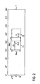
- the omnidirectional camera is commercially available; by which images of a 360-degree panoramic object, with a predetermined reference direction at zero degree as shown in Fig. 2, for instance, are formed on a rectangular two-dimensional image sensor device 7, such as CCD, from which photoelectric conversion signals corresponding to respective pixels can be extracted.
- the remote image sensing device 2 is capable of image sensing of a 360-degree surrounding panoramic object 6.
- a captured video signal of a part of the panoramic object by the remote image sensing device 2 for example, a part (hereinafter referred to as a partial object) 61 in a direction 180 degrees away from the reference, that is, each pixel signal of an area 71 in the image sensor device 7 in Fig. 2 is extracted and sent over a transmission line 4 to the image capturing device 1.
- the image capturing device 1 sends the received captured video signal of the partial object over a transmission line 5 to a camera-equipped portable terminal 3 that is located at a place different from the remote image sensing device 2 and serves also as image display means.
- a camera-equipped portable telephone as the camera-equipped portable terminal 3, but it may be a camera-equipped PDA (Personal Digital Assistance) or camera-fixed PDA terminal as long as it is equipped with a digital video camera and communicating means and can be manually operated to take pictures.
- the transmission lines 4 and 5 they will hereinafter be referred to as a remote transmission line 4 and a portable-associated transmission line 5, respectively.
- Both of the transmission lines 4 and 5 may be dedicated transmission lines or transmission lines that pass through one or more communication networks, such as the Internet, or wireless/wire public telecommunication network.
- the camera-equipped portable terminal 3 is also provided with image display means, and the captured video signal of the partial object 61, sent from the remote image sensing device 2 and received from the image capturing device 1, is played back by the image display means and displayed on its display surface 32a.
- a user holds the camera-equipped portable terminal 3 in his hand and takes pictures of a surrounding object 8 by a camera (portable image sensing means) 33 of the terminal 3; as he sees the partial object 61 in the panoramic object 6 displayed on the display surface 32a, if he wants to see another partial object in the panoramic object 6 that he wishes to display at a remote place, then the user operates the camera-equipped portable terminal 3 to direct its camera 33 to take pictures of the partial object desired to see. For example, in the case of taking pictures of a partial object 62 in a direction 45 degree away to the right from the partial object 61, the direction 33a of the camera 33 of the camera-equipped portable terminal 3 is turned 45 degrees to the right as indicated by the one-dot chain line in Fig. 1.
- the video signal of the surrounding object being image sensed by the camera 33 of the camera-equipped portable terminal 3 (which video signal will hereinafter be referred to as a surrounding video signal) is sent over the portable-associated transmission line 5 to the image capturing device 1.
- the image capturing device 1 detects a change in the surrounding image being shot by the camera-equipped portable terminal 3 from the previous and current surrounding video signals.
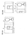
- the range over which the camera-equipped portable terminal 3 is shooting the surrounding object 8 is a shooting range 8b shifted to right from that 8a as shown in Fig. 3A. Accordingly, the received surrounding video signal at the time of seeing the reproduced image of the partial object 61 is the video signal of the shooting range 8a shown at the upper side of Fig. 3B, but the received surrounding video signal with the shooting direction of the camera-equipped portable terminal 3 turned 45 degrees to right is the video signal of the shooting range 8b shown at the lower side of Fig. 3B. Comparison of the both received surrounding video signals indicates that the same image part shifts from right to left in the drawing, from which it is possible to detect that the shooting direction of the camera-equipped portable terminal 3 has been turned to right.
- the image capturing device 1 detects variation information about the received surrounding video signal with respect to the previous one, then based on the variation information, changes the video signal to be extracted from the video signal being shot by the remote image sensing device, and instructs the remote image sensing device 2 so that the partial object in the panoramic object 6 corresponding to the extracted video signal changes corresponding to the change in the image of the received surrounding video signal.
- the image capturing device 2 instructs the remote image sensing device 2 via the remote transmission line 4 to extract the video signal corresponding to the partial object 62 to which the partial object 61 of the panoramic object 6 has turned 45 degrees to right and to extract the video signal of the area 72 to which the area 71 on the image sensor device 7 in Fig. 2 has turned 45 degrees to right.
- the remote image sensing device 2 Upon receiving the instruction, the remote image sensing device 2 extracts the video signal from the area 72 of the image sensor 7, and sends the extracted video signal to the image capturing device 1 via the remote transmission line 4, and the image capturing device 1 sends the received video signal to the camera-equipped portable terminal 3 via the portable-associated transmission line 5.
- the camera-equipped portable terminal 3 displays on its display surface 32a the reproduced image corresponding to the partial object 62.
- the remote image sensing device 2 always shoots the panoramic object 6 and responds to the capturing instruction from the image capturing device 1 to send at all times the video signal of the partial object via the image capturing signal to the camera-equipped portable terminal 3 at the rate of 30 frames per second, for instance.
- the camera-equipped portable terminal 3 also sends its surrounding video signal to the image capturing device 1 at all times.
- remote shooting and displaying of a desired partial object can be achieved by operating the camera-equipped portable terminal 3 to shoot the part of the panoramic object 6 desired to display while directly watching the panoramic object-this provides enhanced operability of the camera and makes it unlikely to incur the deviation between the desired partial object and the reproduced image of its video signal.
- the operability is poor because of the key operation, and since the keys are small and closely packed, an erroneous operation is likely to occur, but the method of the present invention is free from such a possibility.
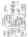
- Fig. 4 illustrates in block form an example of the system configuration of Embodiment 1 of the present invention.
- the same reference numerals denote parts of the same function and no duplicate description will be given of them.
- the image capturing device 1 is provided with: surrounding image receiving means 11 that receives a surrounding video signal sent from the camera-equipped portable terminal 3 over the portable-associated transmission line 5; variation detecting means 12 that detects a variation in the image of the received surrounding video signal as variation information; capturing signal generating means 13 that generates a capturing signal based on the detected variation information; sending means 14 which sends the generated capturing signal to the remote image sensing device 2 over the remote transmission line 4; and image relay means 15 that receives the captured video signal sent from the remote image sensing device 2 over the remote transmission line 4 and passes it to the camera-equipped portable terminal 3 over the portable-associated transmission line 5.
- the remote image sensing device 2 is provided with: an omnidirectional camera 21 as remote image sensing device means for image sensing of a panoramic object; signal receiving means 23 that receives the capturing signal sent from the image capturing device 1 over the remote transmission line 4; image extracting means 24 that extracts the captured video signal of a partial object from the omnidirectional camera 21; and image sending means 22 that sends the captured video signal to the image capturing device 1 over the remote transmission line 4.
- an omnidirectional camera 21 as remote image sensing device means for image sensing of a panoramic object
- signal receiving means 23 that receives the capturing signal sent from the image capturing device 1 over the remote transmission line 4
- image extracting means 24 that extracts the captured video signal of a partial object from the omnidirectional camera 21
- image sending means 22 that sends the captured video signal to the image capturing device 1 over the remote transmission line 4.
- the camera-equipped portable terminal 3 is provided with: image receiving means 31 that receives the captured video signal sent from the remote image sensing device 2 over the portable-associated transmission line 5; image display means 32 that plays back and displays the received captured video signal; a digital video camera 33 that is portable image sensing means for image sensing of surrounding objects; and sending means 34 that sends the surrounding video signal fed thereto from the camera 33 to the image capturing device 1 over the portable-associated transmission line 5.
- the thus extracted signal is output as a captured video signal of the area 71. That is, in this example the center position of the partial object desired to extract and the zoom amount are specified by the capturing signal.
- the capturing signal is composed of reference pixel position signals x, y and a zoom in/out signal a p .
- the captured video signal is sent via the image capturing device to the camera-equipped portable terminal 3, and the image of the partial object in the panoramic object being image sensed by the remote image sensing device 2, in this example, the image of the partial object 62 in Fig. 1, is displayed on the image display means 32 of the camera-equipped portable terminal 3.
- the variation detecting means 12 of the image capturing device 1 detects, from the received surrounding video signal, information about a variation between the image of the current video signal (which image will hereinafter be referred to as the current image) and the image of the previous video signal received from the camera-equipped portable terminal 3.
- the received surrounding video signal is stored in a receiving buffer memory 12a, before which the surrounding video signal previously received and stored in the receiving buffer memory 12a is stored in a previous frame memory 12b.
- the surrounding video signals stored in the memories 12a and 12b are both input to a variation detecting part 12c.
- the variation detecting part 12c detects the direction of movement from the previous image to the current one or the degree of movement (distance) or/and a change in the size of the object of the current image with respect to the previous image, i.e., the zoom amount, are detected.
- the variation information can be detected, for example, by techniques for analyzing the camera operation during shooting, that is, what is called camera work.
- the camera work analysis technique is disclosed, for example, in Yukinobu TANIGUCHI, et at., "PanoramExcerpts: Video Cataloging by Automatic Synthesis and Layout of Panoramic Images," IECEJ Journal D-II, Vol. J82-D-II No. 3, PP.
- the parameters a, d x and d y are calculated which minimize the following square error between the images f(x, y) and f' (x', y'): 1 / N ⁇ ⁇ x , y ⁇ f x ⁇ y - f ⁇ x ⁇ ⁇ y ⁇ ⁇ ⁇ 2 .
- These parameters a, d x and d y are used as the variation information.
- the variation detecting part 12c calculates, for example, a, d x and d y to obtain the variation information; that is, a is zoom in/out information, and d x and d y direction information.
- the capturing signal generating means 13 generates, from the variation information detected by the variation detecting means 12 and a previous capturing signal, a capturing signal that is used to obtain the captured video signal of the partial object of the panoramic objection.
- a capturing signal that is used to obtain the captured video signal of the partial object of the panoramic objection.
- capturing signals x, y and a p for instance, generated previously and currently used are stored in a previous signal memory 13a; these signals x, y and a p and the variation information, for example, d x , d y and a x , are calculated by x +d x ⁇ x in an adding part 13b, y +d y ⁇ y in an adding part 13c, and a p ⁇ a ⁇ a p in a multiplying part 13d, and they are complemented to generate new capturing signals x, y and a p , which are provided to the previous signal memory 13a to update the capturing signals stored therein,
- the image capturing device 1 While the image capturing device 1 does not perform the image capturing processing, there stored in the previous signal memory 13a, as initial values, predetermined capturing signals, for example, the center, x, y, of the sensor device in Fig. 2 and a half value, a p , of the maximum zoom amount; upon the image capturing device 1 starting the capturing processing, the initial value signals x, y and a p in the previous signal memory 13a are sent as capturing signals to the remote image sensing device 2.
- predetermined capturing signals for example, the center, x, y, of the sensor device in Fig. 2 and a half value, a p , of the maximum zoom amount
- the predetermined values are chosen relatively large, and in the case of using the system to prevent crime in a relatively space, they are chosen relatively small; as for d x , for instance, it is considered to be rounded down to 0 when it is 5 or smaller at minimum.
- the capturing signals may be sent to the remote image sensing device 2 at appropriate time intervals. This time interval may be determined properly based on the usage pattern of the system: for example, every 1/10 sec when conditions of the object change relatively rapidly as in the case of traffic monitoring; when the object is scenery, every 1/3 sec, for instance, and in some cases, every several seconds.
- an update instructing part 12d is provided, for example, in the variation detecting means 12, and the receiving buffer memory 12a responds to an instruction from the update instructing part 12d to capture the surrounding video signal of one frame at preset update time intervals, and the variation detecting part 12c detects variation information at the update time intervals.
- the contents of the receiving buffer memory 12a are updated for each frame of surrounding video signals and, upon each detection of variation information, the contents of the receiving buffer memory 12a are transferred to the previous frame memory 12b.
- the capturing signals may selectively be generated and transmitted in correspondence only to those pieces of the variation information which have undergone changes.
- the capturing signals received by the signal receiving means 23 are input to the image extracting means 24 as shown in Fig. 4, and the previously received capturing signals stored in a storage part 24a with the newly received capturing signals.
- the image extracting means 24 Based on the thus updated capturing signals in the storage part 24a, the image extracting means 24 extracts the video signal of the partial object in the panoramic object being shot by the omnidirectional camera 21. For example, the output of the image sensor device 7 of the omnidirectional camera 21 changes, as shown in Fig.
- the updated pieces of information x, y, a p are each added with a prime ['] to distinguish between them and the yet-to-be updated pieces of information.
- d x D 1 .
- the captured video signal extracted from the omnidirectional camera 2 is sent from the image sending means 22 to the camera-equipped portable terminal 3 via the image capturing device 1. Accordingly, the image to be displayed on the image display means 32 of the camera-equipped portable terminal 3 also changes. That is, the desired partial object in the panoramic object changes in accordance with the camera work (direction and/or zoom operation) of the camera-equipped portable terminal 3, and the captured video signal of the changing partial object is reproduced and displayed on the image display means 32.
- the zoom amount a p will be described; at the time of the maximum zoom amount a PM , the image extracting means 24 extracts pixel signal of the image sensor device 7 (Fig. 2), 2I in the x-direction and 2J in the y-direction.
- the zoom amount is a p
- 2I and 2J signals are extracted in the x- and y-directions, respectively at intervals of a PM /a P pixels.
- the zoom amount a p when the zoom amount a p is large, the captured video signal of the partial object is extracted from a narrow area in the image sensor device 7, whereas when a p is small, the captured video signal of the partial object is extracted from a wide area, and the image that is displayed on the image display means 32 of the camera-equipped portable terminal 3 is also zoomed in/out with a change in the zoom amount a p .
- the image relay means 15 of the image capturing device 1 sends the captured video signal received from the remote image sensing device 2 to the camera-equipped portable terminal 3 after a converting part 15a (see Fig. 4) introduces changes into the video signal according to the rating of the camera-equipped portable terminal 3 and the specs of the portable-associated transmission line 3, such as conversion of the screen size of the captured video signal to the screen size of the image display means 32 and conversion of amplitude (luminance) resolution or compression coding for each pixel.
- the camera-equipped portable terminal 3 sends a starting access to the image capturing device 1 (F1).
- the image capturing device 1 sends the starting access or capturing signal (initial value) to the remote image sensing device 2 (F2).
- the remote image sensing device 2 extracts the captured video signal of a partial object predetermined or corresponding to the capturing signal (which "captured video signal” will hereinafter be referred to also as “captured signal” in some cases) (F3), and the captured signal is sent to the image capturing device in real time (F4).
- the image capturing device 1 relays the received captured signal to the camera-equipped portable terminal 3 (F5).
- the camera-equipped portable terminal 3 plays back the received captured signal to display the image of the partial object (F6).
- the image sensing of the surrounding object is performed by the camera-equipped portable terminal 3 (F7).
- the surrounding video signal by the image sensing operation is sent to the image capturing device 1 in real time (F8).
- the image capturing device 1 detects a change in the camera operation of the camera-equipped portable terminal 3 from a change in the image of the received surrounding video signal (F9), and if such a change is detected, generates capturing signal (F10) and sends the capturing signal to the remote image sensing device 2 (F11)
- the remote image sensing device 2 changes, based on the received capturing signal, the video signal of the partial object to be extracted (F12). This is followed by the repetition of processing succeeding that F3 of extracting the captured signal according to the capturing signal, and upon sending an end command from the camera-equipped portable terminal 3 to the image capturing device 1 (F13), the image capturing device 1 relays the end command to the remote image sensing device 2 (F14), and the remote image sensing device 2 stops sending of the captured signal of the partial object (F15).
- step S7 If the variation detection timing is not reached in step S7, then go to step S4, and if the operation resume command is received in step S12, then hold the command and, for example, set a flag, followed by the return to step S6.
- the captured signal of the partial object is played back and displayed on the camera-equipped portable terminal 3; if the user wants to see an image of a partial object different from that being displayed or to zoom it in or out, the camera operation command is sent from the camera-equipped portable terminal 3 to the remote image sensing device 1 for a desired camera operation, and upon displaying an image of the desired partial object, the operation stop command is sent.
- the user is allowed to keep on seeing the image of the partial object, for example, while carrying the camera-equipped portable terminal 3 with him.
- the partial object desired to see can be switched, as required, simply by issuing the operation resume command.
- the image capturing device 1 may send the end command to the remote image sensing device 2 as required (S 14) to cause the remote image sensing device 1 to end transmission of the captured signal of the partial object immediately upon receiving the end command.
- Another possible method is to end the transmission of the captured signal a certain time elapsed after the first sending of the captured signal of the partial object.
- the surrounding video signal may also be received in the interval between the reception of the starting access and the reception of the operation command as indicated by the broken line in Fig. 7. While in the above the variation detecting timing is checked in step S7 to thereby perform the variation detection processing, for example, at a preset time intervals, it is also possible to omit step S7 and perform the variation detection processing at all times.
- the variation detection processing may be followed by determining whether the currently received surrounding image differs from the previously received surrounding image, and if no change is found, the procedure goes to step S4, whereas if a change is found, the procedure goes to step S9 (S15).
- Embodiment 1 the omnidirectional camera is used as the image sensing means of the remote image sensing device 2 and the image capturing device 1 sends the capturing signal to the remote image sensing device to cause it to extract the partial-object captured signal
- Embodiment 2 an omnidirectional camera is used as image sensing means of the remote image sensing device 2, and the remote image sensing device 2 is caused to send all captured video signals to the image capturing device 1, and the image capturing device 1 extracts the partial-object captured signal from the received captured video signals.
- Fig. 8 illustrate an example of the system configuration of this embodiment. The following description will be given only of the parts different from those in Fig. 4.
- the image extracting means 24 is omitted, and all the captured video signal of the omnidirectional camera 21 are sent from the video sending means 22 to the image capturing device 1.
- the signal receiving means 23 may be left out, but instead provision may be made such that the remote image sensing device responds to the starting access from the image capturing device 1 to start image sensing by the omnidirectional camera 21 or start transmission of captured video signals to the image capturing device 1 and responds to the end command to end the transmission of the captured video signals to the image capturing device 1.
- the image capturing device 1 there are provided remote image receiving means 16, image extracting means 17 and image sending means 18, and no capturing signal is sent to the remote image sensing device 2.
- the captured video signal from the remote image sensing device 2 is received by the remote image receiving means 16, and the capturing signal from the capturing signal generating means 13 is used to extract the partial-object captured signal by the image extracting means 17.
- the received captured video signal is stored in a buffer memory 17a in the image extracting means 17; in this case, the video signal is stored with respective pixel signals arranged in the same pattern as that of the pixel arrangement in the image sensor device 7 shown in Fig. 2, for instance.
- the partial-object captured signal is read out from the buffer memory 17a based on the capturing signal in the previous memory 13a (see Fig. 5) in the capturing signal generating means, in this example, based on reference pixel position signals x, y and the zoom-in/out signal a p .
- the thus read-out partial-object captured signal is sent from the image sending means 18 to the camera-equipped portable terminal 3.
- processing of the captured signal such as the screen size conversion and compression processing, may be performed in the converting part 18a before its transmission as in Embodiment 1.
- the starting access and the end command may be sent, as required, by the signal sending means 14 to the remote image sensing device 2.
- This embodiment is identical with Embodiment 1 except the above.
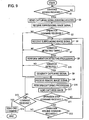
- Fig. 9 shows an example of the procedure of the image capturing device 1 in Embodiment 2. As is the case with the procedure depicted in Fig. 7, steps S 1, S2 and S3 are performed. If no command for camera operation is received in step S3, the captured video signal is received from the remote image sensing device 2 in step S4', then in step S16 a partial-object captured signal is extracted from the received captured video signal based on the variation information stored in the previous signal memory 13a, and in step S17 the thus extracted partial-object captured signal is sent to the camera-equipped portable terminal 3.
- step S11 After sending the captured image, the procedure goes to step S11, in which it is determined if a camera operation stop command is received as in Embodiment 1, then steps S 12 and S 13 are sequentially performed, and if no end command is received, the procedure goes to step S4.
- This embodiment is identical with Embodiment 1 except the above and produces the same working-effect as that obtainable with the latter.
- the flow of processing as the system is the same as in Embodiment 1 except that: the remote image sensing device 2 sends all the captured video signal to the image capturing device 1 in step F3; step F12 is omitted; and the image capturing device 1 performs the processing shown in Fig. 9.
- Embodiment 3 uses a plurality of digital video cameras as image sensing means of the remote image sensing device 2, and the image capturing device 1 captures a video signal of a partial object in a panoramic object by extracting it in the remote image sensing device 2.
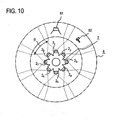
- Fig. 10 there are shown, by way of example, relationships between the remote image sensing device 2 and the panoramic object 6 in Embodiment 3.
- camera devices 2 1 to 2 8 having eight video cameras, as the remote image sensing device 2 are set over 360 degree with their shooting directions held at equal angular intervals.
- the viewing angles ⁇ of the camera devices 2 1 to 2 8 each chosen to be a little larger than the angular distance of 45 degrees in this example so that the fields of adjacent camera devices partly overlap to permit image sensing continuous partial objects of the panoramic object.
- the panoramic object 6 forms a cylindrical surface at the same distance from the remote sensing device 2, but in the interests of easy understanding of partial objects, the panoramic object 6 is shown with its lower diameter smaller than the upper one.
- the camera device 2 1 shoots the partial object 61
- the camera device 2 2 shoots the partial object 62 in the direction 45 degrees away to the right from the direction of shooting the partial object 61.
- this remote image sensing device 2 it is possible to shoot any of the partial objects into which the panoramic object 6 is divided equally by the number 2 n of camera devices used.
- the number of camera devices is not limited specifically eight.
- the angular distance of the shooting direction needs not always be equal, that is, when the panoramic object 6 contains a part unnecessary to see, the camera devices are so directed as not to shoot such an unnecessary part.
- the remote image sensing device 2 has a plurality of camera devices 2 1 to 2 N disposed as shown in Fig. 10, for instance.
- the camera devices 2 1 to 2 N have the same construction, which will be described below in connection with the camera device 2 1 .
- the image extracting means 24 is used as in the case of Fig. 4, but its construction and processing (operation) differs from the image extracting means 24 in Fig. 4. That is, the capturing signal received from the image capturing device 1 is composed of camera identification information IDp and, if necessary, a zoom parameter a p or/and a position parameter y.
- the image extracting means 24 is provided with a storage part 24a for storing a p , y and ID storage part 24b for storing the camera identification information ID1 of the camera device 2 1 .
- the storage part 24a is omitted.
- the camera 21 of the camera device 2 1 begins shooting and image capturing processing is performed; otherwise, the camera 21 is always held in shooting state and images are captured from the camera 21.
- the stored contents a p and y in the storage part 24a are updated with a p and y in the capturing signal, respectively.
- the image extraction processing can be performed substantially in the same manner as in the case of Embodiment 1, but when a P and y are not used, the image signal output from the camera 21 is captured as a partial-object captured signal from the camera 21 and input to the image sending means 22.
- the image sensor device 7 of the camera 21 is rectangular, for instance, as depicted in Fig.
- the breadth is defined by the number of pixels, 2(a PM /a PS )I, which is a value obtained by multiplying the number of horizontal (x-direction) pixels of the image to be displayed, 2I, by a value (a PM /a PS ) which is obtained by dividing the maximum value a PM of a P by the minimum value a S of a P , and th length is defined by the number of pixels, 2(a PM /a PS ) ⁇ y M ⁇ J, that is a value obtained by multiplying the number of vertical (y-direction) pixels, 2J, of the image to be displayed by 2(a PM /a PS ) and further multiplying by the number of pixels, ⁇ y M , for the maximum tilt angle (of elevation/depression).
- the minimum value a PS of a P is determined by the number of pixels in the breadthwise direction of the device 7, and the maximum tilt angle (of elevation/depression) ⁇ y M is determined by the minimum value a PS based on the number of pixels in the lengthwise direction of the device 7.
- signals of pixels ((a PM /a P ')i, y'+(a PM /a P ')j) are captured as a partial-object captured signal from an area 72 of a breadth 2(a PM /a P ')I and a length 2(a PM /a P ')J with its center at a position y' on the center line.
- the remote image sensing device 2 the partial-object captured signal is taken out from any one of the camera devices 2 1 to 2 N in accordance with the capturing signal sent from the image capturing device 1, and the signal is sent by the image sending means 22 to the image capturing device 1.
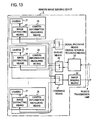
- the remote image sensing device 2 and the image capturing device 1 may be interconnected as shown in Fig. 11, in which the camera devices 2 1 to 2 N are connected via partial lines to the image capturing device 1, but the remote image sensing device 2 and the image capturing device 1 may also be connected via one two-way transmission line 4 as depicted in Fig. 13.
- the capturing signal from the image capturing device 1 is received by the signal receiving means 23, then the received capturing signal is distributed by dividing means 26 to the image extracting means 24 of each of the camera devices 2 1 to 2 N , then the partial-object captured signals from the respective cameras 21 of the camera devices 2 1 to 2 N (normally, from only one of them) are combined by combining means 27, and the combined partial-object captured signal is send by the image sending means 22 to the image capturing device 1.
- Fig. 14 shows an example.
- the number N of camera devices 2 N is 8, and respective pieces of camera identification information of the camera devices 2 1 to 2 N are represented by ID 1 to ID8.
- the angular distance ⁇ 1 between the camera devices 2 1 and 2 2 in the shooting direction (a value in terms of number of pixels of the captured image on the display surface; the same applied to the following description) is stored for ID1 ⁇ ID2, and the angular distance ⁇ 2 between the camera devices 2 2 and 2 3 in the shooting direction is stored for ID2 ⁇ ID3, and the angular distances between the other adjacent camera devices are similarly stored.
- the capturing signal generating means 13 somewhat differs in construction and processing (operation) from the counterpart in Fig. 4.
- Fig. 14 there is shown an example of its functional configuration.
- the variation detecting means 12 is shown to detect, as the variation information, the direction information d x , d y and the zoom information a by such configuration and method as referred to previously with reference to Fig. 5.
- the previous camera identification information IDp, the y-direction position y and the zoom amount a p are stored.
- the information d x is input to a camera identifying part 13b.
- the processing in the camera identifying part 13b will be described below with reference to Fig. 15. If the sign of d x is positive (S1), the angle ⁇ x +1 between the camera shooting direction in the previous camera identification information IDp and the camera shooting direction in the current camera identification information IDp+ 1 is read out of the camera direction storage means 19 using IDp BDp+1 as an address (S2).
- a check is made to determine whether d x is equal to or greater than ⁇ x +1 (S3), and if it is equal to or greater than ⁇ x +1 , IDP+1 is output (S4), and if it is not equal to or greater than ⁇ x +1 , IDp is output intact (S5).
- step S1 If the sign of d x is not positive in step S1, then the angle ⁇ x -1 between the camera shooting directions in IDp-1 and IDp is read out of the storage means 19 using IDp-1 ⁇ IDp as an address (S6), then a check is made to determine whether the absolute value of d x is equal to or greater than ⁇ x -1 (S7), and if so, IDp-1 is output (S8), and if it is not equal to or greater than ⁇ x -1 , IDp is output intact (S9)
- steps S4 and S8 are omitted as indicated by the broken lines in Fig. 15; if d x is equal to or greater than ⁇ x +1 in step S3, the angular distance from the shooting direction of the adjoining camera, that is, the angular distance ⁇ x +1 between the camera shooting directions in IDp+1 and IDp+2, is read out from the storage means 19 (S10), then a check is made to determine whether d x is equal to or greater than ⁇ x +1 + ⁇ x +2 (S11), and if so, IDp+2 is output (S12), and if it is not equal to or greater than ⁇ x +1 + ⁇ x +2 , IDp+1 is output (S13).
- the angular distance from the shooting direction of the adjoining camera that is, the angular distance ⁇ x -2 is read out of the storage means 19 using IDp-2-IDp-1 (S 14), and a check is made determine whether
- IDp-2-IDp-1 S 14
- step S3 a check is made to determined if ⁇ x ⁇ d x
- step S7 a check is made to determine if ⁇ x ⁇
- step S11 a check is made to see if 2 ⁇ x ⁇ d x
- step S15 a check is made to see if 2 ⁇ x ⁇
- d y is added with the previous information y in the adding part 13c and a is multiplied by the previous information a P in the multiplying part 13d as described previously with respect to Fig. 5.
- the outputs from the respective parts 13b, 13c and 13d are provided to the signal sending means 14, while at the same time the contents of the previous signal memory 13a are updated in the same manner as described previously.
- the discarding parts 13e, 13f and 13g may be provided. In this instance, when d x is equal to or smaller than a preset value in the discarding part 13e, the present value IDp (IDp in the memory 13a) is output without the processing in the camera identifying part 13b.
- the camera direction storage means 19 there may be prestored the angles of shooting directions of the camera devices with respect to the direction shooting of a predetermined one of them as depicted in Fig. 16, for instance.
- the shooting direction of the camera device of the camera identification information ID4 is used as a standard of reference and the angles of the shooting direction of each of the other seven camera devices with respect to this reference direction is stored as the number of pixels in one frame of the captured image.
- the angles in IDp and IDp+1 are read out, for example, in step S2 and it is decided whether d x is equal to or greater than the difference between the two angles.
- the respective pieces of camera identification information be made to correspond to north, south, east and west directions, for example, north, north-east, east, ... directions.
- the correspondences between the camera identification information and the north, south, east and west directions may be defined by predetermining the shooting direction of the camera device of each camera identification information and placing the remote image sensing device 2 accordingly. In some case, however, such placement of the remote image sensing device 1 is time-consuming. To avoid this, as shown in Fig.
- camera information measuring means 25 is provided in each of the camera devices 2 1 to 2 N , and the angle of the shooting direction with respect to true north is measured by a magnetic compass or similar direction sensor 25a of the camera information measuring means 25 to obtain the information about the shooting direction of each camera device in north, south, east, or west direction.
- a tilt angle sensor 25b as by a gravitational accelerometer is also provided, by which is detected a value ⁇ y that represents, in terms of the number of pixels on the frame of the captured image, the angle of the shooting direction to the horizontal plane, that is, the angle (angle of elevation/depression) of the y-axis of the image sensor device 7 of the camera 21.
- the image capturing device 1 receives from each camera device 2 n its identification information IDn, north, south, east or west direction and tilt angle ⁇ yn by the signal sending/receiving means 14, and stores them in the camera direction storage means 19 in correspondence to the identification IDn as shown in Fig. 16, for instance.
- the image capturing device 1 When the user makes a starting access to the image capturing device 1, the image capturing device 1 reads out the identification information of the camera, ID3 in the Fig. 16 example, whose shooting direction is a predetermined one of the north, south, east and west directions, for example, north direction ID3 in the Fig. 16 example and the elevation/depression angle ⁇ y3 , and sends these read-out values to the remote image sensing device 2, if necessary, together with the initial value a p of the zoom in/out parameter (zoom value).
- the initial value a p may be prestored in the storage part 24a of the image extracting means 24 in each of the camera devices 2 1 to 2 N .
- the elevation/depression angle ⁇ yn is subtracted from the output from the adding part 13c in a correcting part 13h in Fig. 14, and is fed to the signal sending means 14.
- the updating of y in the previous signal memory 13a is performed using the value yet to be corrected in the correcting part 13h.
- a partial-object video signal is sent from the camera device 2 n to the image capturing device 1 to capture the signal, which is relayed and sent to the camera-equipped portable terminal 3 as in the case of Embodiment 1; accordingly, it can easily be understood that the user can see the panoramic object directly and select its partial object while operating the camera of the portable terminal 3 as in Embodiment 1.
- the procedure of the image capturing device 1 in this instance is the same as shown in Fig. 7.
- the procedure in this case may also be changed such that upon receiving the starting access, the image capturing device sends it to the remote image sensing device 2, which responds to the starting access to send a partial-object captured signal from a predetermined camera device 2 n to the image capturing device 1.
- the image capturing device 1 can extract a partial-object captured signal from the video signal received from the remote image sensing device 2 as in the case of Embodiment 2.
- Embodiment 4 concerns this operation, and its differences from Embodiment 3 will be described with reference to Fig. 17.
- the image extracting means 24 of each of the camera devices 2 1 to 2 N is omitted, and the video signal from each camera 21 is sent by the image sending means 22 to the image capturing device 1.
- the camera identification information IDn stored in the ID storage part 24b is added to the video signal of the camera 21 to enable the image capturing device 1 to recognize the camera device 2 n from which the video signal is received.
- the image sending means 22 may be provided for each of the camera devices 2 1 to 2 N , but it may also be provided in common to them.
- the camera information measuring means 25 may be provided as required.
- the image relay means 15 is omitted, and in the image extracting means 17 a selecting part 17b selects that one of the video signal from the camera device 2 1 to 2 N which corresponds to the camera identification information IDp contained in the capturing signal from the capturing signal generating means 13. In other words, that one of the received signal whose camera identification information IDn matches IDp is selected. This selection may be made by the image extracting means 17 itself.
- the image extracting means 17 has the buffer memory 17a that is the same.as in Fig. 8, and in this buffer memory 17a the video signal is stored with its pixel signals arranged in the same pattern as that of the pixel arrangement in the image sensor device 7 shown in Fig. 12, for instance; and the image extracting means 24 extracts the partial-object captured signal in accordance with a P and/or y in the capturing signal as described previously with reference to Fig. 12.
- the buffer memory 17a may be dispensed with.
- the selection of the video signal may be done by a selecting part 16a in the image receiving means 16 in place of the selecting part 17a; alternatively, as described previously, the receiving terminals of the image receiving means are predetermined corresponding to the camera devices 2 1 to 2 N , respectively so that the receiving terminal corresponding to the information IDp is selected to select the received image signal.
- the image capturing device 1 On being accessed for starting from the camera-equipped portable terminal 3, the image capturing device 1 captures a partial-object video signal corresponding to predetermined camera identification information or predetermined one of the north, south, east and west directions, and sends the captured signal to the camera-equipped portable terminal 3.
- the procedure of the image capturing device 1 in the system of Embodiment 4 is the same as the procedure shown in Fig. 9. Hence, it will easily be understood that Embodiment 4 also produces the same working-effect obtainable with Embodiments 1 to 3.
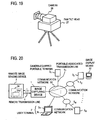
- Embodiment 5 uses, as the image sensing means of the remote image sensing device 2, a video camera mounted on a panhead.
- Fig. 18 illustrates an example of the system configuration of this embodiment. A description will be given of differences from Fig. 4 configuration.
- the image sensing means 21 of the remote image sensing device 2 is a video camera 28 mounted on a panhead 27 as shown in Fig. 19; the shooting diction of the camera 28 can be changed by a control signal from a remote location, and the field angle, i.e., what is called zoom amount, can also be changed by the lens.
- the image sensing means 21 will hereinafter be referred to as a panhead camera 21.
- To the image extracting means 24 are input, as capturing signals, an azimuth signal ⁇ , an elevation/depression angle signal ⁇ and a zoom signal Z from the image capturing device 1.
- An azimuth control signal 24c controls an azimuth angle control mechanism 24d according to the azimuth signal ⁇ , causing the azimuth angle of the shooting direction of the camera 21 to become ⁇ .
- An elevation/depression control part 24e controls an elevation/depression control mechanism 24f according to the elevation/depression angle signal ⁇ , causing the elevation/depression angle of the shooting direction of the camera to become ⁇ .
- a zoom control part 24g controls a zoom control mechanism 24h according to the zoom signal Z, causing the zoom amount of the camera 21 to become Z.
- the partial-object image signal in the panoramic object 6 corresponding to the capturing signals is taken out from the camera 21 and sent to the image capturing device 1.
- the remote image sensing device 2 can also be provided with the camera information measuring means 25 described previously with respect to Fig. 11;
- the capturing signal generating means 13 such as shown in Fig. 5, generates signals z, x and a p based on the variation information detected by the variation detecting mean 12, and these signals x, y and a P are converted by a converting part 13j to direction signals of the azimuth signal ⁇ and the elevation/depression angle signal ⁇ , and a zoom change signal of the zoom signal Z, which are sent to the remote image sensing device 2.
- the remote image sensing device 2 Upon sending a starting access from the image capturing device 1 to the remote image sensing device 2, the remote image sensing device 2 sends to the image capturing device 1 a partial-object video signal obtained by shooting in a preset reference direction and with a reference zoom amount.
- camera information measuring means 25 is provideod, and in the case where the image capturing device 1 responds to a starting access to obtain a partial-video signal in a predetermined direction, for example, in the north direction and in the horizontal direction, an initial signal generating part 13 k generates initial capturing signals.
- the azimuth angle ⁇ i and elevation/depression angle ⁇ i measured by the camera information measuring means 25 of the remote image sensing device 2 are stored in storage parts 13 m and 13 n , respectively, and direction-containing angle signals of differences between the stored angles ⁇ i , ⁇ i and predetermined reference azimuth angle and reference elevation/depression angle are calculated in reference calculating parts 13p and 13q, and these signals are sent as initial capturing signals to the remote image sensing device 2. That is, the difference between the current shooting direction of the panhead camera 21 and the reference direction is sent as the capturing signal to the remote image sensing device 2, which responds to the capturing signal to control the panhead camera 21 to change its shooting direction by the above-mentioned difference.
- the initial capturing signal is zero in difference.
- the capturing signals based on the variation information detected by the variation detecting means 12, which indicate the current conditions of the panhead camera 21, that is, only variations in the shooting direction and in the zoom amount are also sent to the remote image sensing device 2.
- the pieces of variation information d x , d y and a detected by the variation detecting means 12 are directly input to a converting part 13j of the capturing signal generating means 13, and respective converted outputs are sent as generated capturing signals to the remote image sensing device 2.
- the remote image sensing device 2 controls the azimuth control mechanism 24d, the elevation/depression control mechanism 24f and the zoom amount control mechanism 24h by the variations represented by the received capturing signals corresponding to them, respectively.
- Embodiment 6 is so adapted as to permit a plurality of users to use the remote image sensing device 2.
- the image capturing device 1 is connected to a communication network 5 0 , and plural camera-equipped portable terminals 3 1 , 3 2 , ..., 3 M are connected directly to the communication network 5 0 or connected to the communication network 5 0 via another network, constituting portable-associated transmission lines 5 1 , 5 2 ,..., 5 M connected to the image capturing device 1.
- the image capturing device 1 is connected to the remote image sensing device 2 via the remote transmission line 4.
- the remote transmission line 5 may be a dedicated line or a line passing through the communication network 5 0 .
- the control means 93 is provided with a memory having stored therein a program necessary for controlling a microprocessor or CPU (Central Processing Unit) to function as the image capturing device 1, and executes the program to effect a read and a write of each memory and operate the respective parts in a sequential order.
- a microprocessor or CPU Central Processing Unit
- a certain camera-equipped portable terminal 3 uses a line s until completion of reception of a partial-object image signal after connecting to the surrounding image receiving means 11 of the line number s to make a starting.
- the capturing signals are read out of that area in the previous signal memory 13a corresponding to the line s, and the read-out capturing signals are used to extract, by the image extracting means 17, a partial-object video signal from a panorama video signal received by the remote image receiving means 17, and the extracted partial-object video signal is sent to the camera-equipped portable terminal 3 by the image sending means 18s of the line number s.
- the previous signal memory 13a In its initial state the previous signal memory 13a has stored in its all areas capturing signal, x 0 , y 0 and a P0 in this example, for predetermined partial objects.
- the camera-equipped portable terminal 3 upon receiving the video signal from the image capturing device 1, the received video signal is played back and displayed by the image display means 32.
- the operation for capturing the partial-object video signal in the image capturing means 17 is carried out in the same manner as described previously in respect of Embodiment 2.
- a flag is set for the line number s in the flag memory 92, that is, the flag is switched from "0" to "1" (the flag being initially set at "0"), then the timer of the update instructing part 12d s is set, and the surrounding video signal received by the surrounding image receiving means 11 s is stored in the receiving buffer memory 12a s .
- the variation information d x , d y , a is detected by the variation detecting part 12c from the both received surrounding video signals in the receiving buffer memory 12a s and the previous frame memory 12b, then the capturing signal generating means 13 generates a capturing signal by processing the previous generating signal in the area s of the previous signal memory 13a based on the detected variation information, then the capturing signal in the area s of the previous signal memory 13a is updated with the newly generated capturing signal, and a partial-object video signal by the image capturing means 17 is sent by the image sending means 18 s to the camera-equipped portable terminal 3.
- the video signal in the receiving buffer memory 12a s is transferred to the area s of the previous frame memory 12b.
- the flag of the line number s in the flag memory 92 is reset to "0," stopping the operation of the update instructing part 12d s .
- the partial-object video signal is captured, and it is send by the image sending means 18 s on a real time basis.
- the flag of the line s in the flag memory 92 is set to "1" to put the update instructing part 12d s in operation, followed by the same processing as in the case of having received the camera operation command.
- the camera-equipped portable terminal 3 m attaches terminal identification information Idm to each signal to be sent.
- the terminal identification information idm used is, for example, the telephone number or address of the camera-equipped portable terminal 3 m or, if necessary, the equipment number of the camera-equipped portable number 3 m , the user's name or so.
- the terminal identification information Idm and an idle processing number s are stored in the processing number memory 91 in correspondence to each other.
- the image capturing device 1 uses its terminal identification information Idm to read out the processing number s from the processing number memory 91, and performs processing corresponding to the read-out processing number s.
- the flag of the processing number s in the flag memory 91 is controlled, and the operation of the update instructing part 12d s is controlled; based on the surrounding video signal, the areas s in the receiving buffer memory 12a s and the previous frame memory 12b are utilized, and the capturing signal in the previous signal memory 13a of the capturing signal generating means 13 and the signal in the memory of the image capturing means 17; and sending of the partial-object video signal is performed by reading out the terminal identification information Idm corresponding to the processing number s in the processing number memory 91 and connecting an idle image sending means 18 s to the camera-equipped portable terminal 3 m of the above-mentioned read-out terminal identification information Idm.
- a plurality of users can see their desired partial-object images via one remote image sensing device 1 by simultaneously operating their camera-equipped portable terminals independently of one another.
- pluralities of variation detecting parts 12c, capturing signal generating means 13 and image capturing means 17 are used at the same time.
- the remote image sensing device 1 used is the same as that shown in Fig. 10, too, a plurality of users can use one remote image sensing device 1 at the same time. That is, in the configuration depicted in Fig. 21 the remote image receiving means 16, the capturing signal generating means 13 and the image capturing means 17 are configured as shown in Figs. 14 and 17; further, to perform simultaneous processing for the plurality of camera-equipped portable terminals 3 m , the image capturing device 1 has, as shown in Fig.
- the plurality of surrounding image receiving means 11 s the plurality of buffer memories 12a s , the plurality of update instructing parts 12d s , the previous frame memory 12b having a plurality of storage areas, the previous signal memory 13a having a plurality of storage areas, the plurality of image sending means 18 s , the flag memory 92, and the control means 93.
- the camera identification IDp is used in place of the signal x in the capturing signal, and processing for each camera-equipped portable terminal 3 m is performed in the same manner as in the case of using the omnidirectional camera, but the partial-object video signal capturing operation is carried out as described previously with reference to Embodiment 4.
- the plurality of users can see simultaneously on the plurality of camera-equipped portable terminals 3 m their desired partial-object images of the video signals in plural directions that are simultaneously received from the plurality of camera devices 2 1 to 2 N .
- the systems of Embodiments 1 and 3 can also be adapted to simultaneously capture partial-objects images by the plurality of camera-equipped portable terminals 3 m .
- the image capturing means 17 in Fig. 21 is omitted, and the capturing signal for the camera-equipped portable terminal 3 m , generated in the image capturing device 1, is attached with, for example, the processing number s for identification use, and sent to the remote image sensing device 2; in the remote image sensing device 1, in the case of the Fig. 4 example, a storage parts 24a' for-storing capturing signals for respective processing numbers are each provided in the image extracting means 24 as indicated by the broken line in Fig.
- the capturing signals in the storage parts 24a corresponding to the received processing numbers are updated, then partial-object video signals are extracted based on the capturing signals stored in the respective storage parts 24a' as described previously with reference to Embodiment 1, and the extracted partial-object video signals, attached with the processing numbers, are sent to the image capturing device 1.
- the image capturing device 1 the partial-object video signals simultaneously received by the camera-equipped portable terminals 3 m , corresponding to the received processing numbers, are relayed and sent; the image capturing means 17 is omitted.
- the storage part 24a for storing the capturing signal for each processing number is provided in the image extracting means 24 of the remote image sensing device 2; the capturing signal in the storage part 24a,corresponding to the received processing number, is updated with the capturing signal received simultaneously with the processing number, then based on each capturing signals IDp, x, a P stored in the storage part 24a, the partial-object video signal is captured from the corresponding camera device 2 n , and the captured vide signal is sent to the image capturing device 1, together with the processing number.
- the image display means 32 may be a fixed display for use in a personal computer or the like, as indicated by the broken lines in Figs. 4, 8, 18 and 20. In any case, however, the display is adapted to play back and display the partial-object video signal sent from the image capturing device 1 to the camera-equipped portable terminal. In this instance, the user operates the camera-equipped portable terminal 3 for camera work while seeing the image displayed on the fixed image display means 32.
- the camera-equipped portable terminal 3 with the image display means 32 fixed thereto as in the above example is very convenient to use since it is possible for the user to use it anywhere even while walking, for example, to see his child in kindergarten.
- the panoramic object 6 needs not always to extend around over 360 degrees, but the object 6 needs only to permit changing the shooting direction or adjustment of the field angle in the case of shooting the object while directly watching it. Further, as referred to previously in respect of Embodiment 3, the panoramic object 6 need not necessarily be continuous. These will readily be understood from the fact that it is sometimes desirable, for example, to shoot only specified parts of a 180-degree scene opening out before the camera or it is used as a security camera for monitoring only several doorways of a building.
- the variation information including its amount of operation is detected and the capturing signal to be generated is corrected corresponding to the variation information, but it is also possible to detect a variation in direction alone without detecting the degree (amount) of the variation and add the predetermined value d x to or subtract it from the previous capturing signal x.
- hysteresis information on the variation information sent to the capturing signal generating means 13 is stored in a hysteresis storage part 12e.
- the hysteresis storage part is configured to always store variation information obtained by, for example, three immediately previous detections. For example, when variation information is detected in the detecting part 12c in Fig. 5, a decision part 12f decides, by comparison, whether the variation information greatly deviates from the continuity of the variation information stored in the hysteresis storage part 12e.
- the variation information is provided to the capturing signal generating means 13, and at the same time, it is stored as the latest information in the hysteresis storage part 12e, removing therefrom the oldest information. If the decision part 12f decides that the currently detected variation information is abnormal, then the variation detecting means discards the information in the rejecting part 12g, or waits for the next update instruction, or receives the surrounding video signal anew and performs variation detection processing.
- each user operates an operating part 3b by means of key, lever, mouse, or track ball to capture from the panorama video signal a moved or/and zoomed version of a desired partial object in the panoramic object 6 being image sensed by the remote image sensing device 1.
- the operating part 3b uses, as d x in the afore-mentioned variation information and the afore-mentioned d y , an x-axis control signal and a y-axis control signal produced by an operation for moving a display on the display screen of a personal computer, for instance, and outputs a control signal for zooming in/out the display on the screen as a in the afore-mentioned variation information, and sends this variation information d x to the image capturing device 1.
- the image capturing device 1 uses mere signal receiving means 11s as a substitute for the surrounding image receiving means 11s, and the capturing signal generating mean 13 generates the capturing signal using the variation information received by the receiving means 11s from each user terminal 3' and the previous capturing signal x (or IDp), y, a P in the previous signal memory 13a according to the processing number based on the line number of the signal receiving means 11 s or simultaneously received user identification information.
- the subsequent processing is the same as in Embodiment 6. But the capturing signal is sent to the user terminal 3'.
- the capturing of the partial-object video signal for each user can be carried out by the image capturing device 1 as in Embodiment 1 or 3.
- the image capturing device 1 generates the capturing signal according to the variation information d x , d y , a received for each user terminal 3' in the same way as described previously, but the capturing signals are IDp, y , a, but as referred to near the end of the description of Embodiment 6, the capturing signal, for example, attached with the processing number, is sent to he remote image sensing device 2, and the remote image sensing device 2 similarly sends the partial-object vide signal corresponding to the capturing signal for each processing number.
- the user terminal 3' has been described as being fixed like a personal computer, it is apparent that it may be a portable telephone, PDA, or similar portable terminal as well. That is, the user terminal is to send to the image capturing device 1 variation information, for example, d x , d y , a, that represent direction and/or zoom with respect to predetermined references so as to specify that partial object in the panoramic object being shot by the remote image sensing device 2.
- the image capturing device 1 variation information for example, d x , d y , a, that represent direction and/or zoom with respect to predetermined references so as to specify that partial object in the panoramic object being shot by the remote image sensing device 2.
- the image capturing device 1 used in each of Embodiments 1 to 6 can be implemented by a computer. That is, the program for executing the functions of each image capturing device 1 is installed on the computer from a recording medium such as a CD-ROM, magnetic disk, and a semiconductor memory, or downloaded to the computer via a communication line for execution by the computer.
- a recording medium such as a CD-ROM, magnetic disk, and a semiconductor memory
Abstract
Description
- The present invention relates to a remote image display method for image sensing of a panoramic object by an image sensor, that is, by a camera (hereinafter referred to simply as camera) that outputs video signals, and for displaying the captured images to a user at a place remote from the camera; the invention also pertains to an image capturing device and method therefor, and an image capturing program.
- For the purpose of observing the traffic on the road, it is now a general practice to set a panhead camera to monitor the traffic conditions; video signals obtained by shooting with the camera are sent over a communication line to a monitor set placed at a remote location, where the received video signals are played back to display the traffic conditions on a display. The watcher manipulates, while watching the display, an operating button or lever of a remote controller to send a control signal for changing the shooting direction (horizontal and vertical directions) of the monitor camera, or/and a control signal for changing the zoom amount of a zoom lens of the camera over the communication line to a control mechanism of the monitor camera to control it for changing its shooting direction and shooting condition (refer to, for example,
Japanese Patent Application Koukai publication No. 205775/99 (published on July 30, 1999 - There is offered a service what is called video live through a panhead camera set on the roof of a high-rise building; a user accesses the camera from his personal computer via the Internet or similar communication network to occupy the camera for a predetermined time, receives shooting video signals of the camera by the personal computer to play back the video signals to provide a display of the images on the display, and while watching the image on the display, the user operates the personal computer to remotely control the camera shooting direction or the zoom amount of the lens to enjoy seeing respective parts of a wide-range panoramic object.
- It is possible for a parent to control a personal computer at his home or office to access a camera set up in kindergarten to play back a video signal from the camera for display on the personal computer and to remotely control the shooting direction or zoom amount of the camera to observe his child's movements under various circumstances.
- Further, when video signals from a security camera set up in a convenience store are played back to display the images on a display at a remote place, it is possible for a watchman to remotely control the shooting direction or zoom amount of the security camera while watching the images being displayed.
- Such remote control of a camera to display video signals therefrom can be used for various purposes. In the prior art, the shooting direction of the camera itself is changed by mechanical control, or the control for mechanically moving the zoom lens is effected by a button (key) operation or level operation using a personal computer. Moreover, while one user remotely controls the camera, other users cannot control the camera; that is, the camera is occupied by one user for a predetermined time, for instance.
- Since the control for obtaining a desired image by a conventional remote image display scheme is remote control of the camera itself by operating a button (key) or lever, the operability of the camera is poorer than in the case of manually operating the camera in one's hand or on the panhead to obtain a desired image, that is, the image thus obtained becomes a little different from the desired one in some cases.
-
WO 99/12349 - An object of the present invention is to provide a remote image display method that permits displaying a desired remote image in the same way a user directly operates the camera by his hand, and an image capturing device and method therefor, and an image capturing program.
- This object is achieved by a method as claimed in
claim 1, an image capturing device as claimed inclaims 2 and 8 and computer programs as claimed inclaims - The panoramic object is sufficiently wide to such an extent as not to be suitable for displaying as an image of one display frame of the image display means, or it can be displayed as the image of one display frame to some extent but it is equal to the range of a visual angle over which each part of the display needs to be seen in detail, and the field angle is 360 degree or less, and the images to be displayed need not always be continuous. There are two schemes for the image capturing device to obtain the video signal of a changed part of the panoramic object from the remote image sensing device. According to the one scheme: variation information on the image of the current surrounding video signal (hereinafter referred to as the current image) with respect to the image of the previous surrounding video signal (hereinafter referred to as the previous image) received from the camera-equipped portable terminal is detected by variation detecting means from the received surrounding video signal; a capturing signal for obtaining a video signal of a part of the panoramic object is generated by capturing signal generating means based on the detected variation information; the generated capturing signal is sent to the remote image sensing device; and the video signal received by the remote image sensing device is sent by image relay means to the image display means. With this scheme, the image capturing device sends the capturing signal to the remote image sensing device and receives the video signal of the changed part of the panoramic object from the remote image sensing device to thereby obtain an image of the video signal of the changed part of the panoramic object.
- According to the other scheme, the user operates the camera-equipped portable terminal in his hand to shoot a part of the panoramic object while watching the image of a part of the panoramic object displayed on the image display means, by which it is possible to remotely shoot and display a desired part of the panoramic object; in this case, the camera can be operated in the same way the user himself operates the camera at the place where he can see the panoramic object directly. Hence, operability of the camera is excellent and no deviation is hard to occur between the desired part of the panoramic object and the displayed image.
-
- Fig. 1 is a diagram illustrating an example of the system configuration for explaining the principles of the present invention.
- Fig. 2 is a diagram for explaining an image sensor device of an omnidirectional video camera and the extraction of an image signal of an each partial object.
- Fig. 3A is a diagram showing, by way of example, how captured images move on the image sensor when a camera-equipped portable terminal is turned in the direction of taking pictures.
- Fig. 3B is a diagram showing images before and after they move in Fig. 3A.
- Fig. 4 is a block diagram illustrating an example of the system configuration of
Embodiment 1. - Fig. 5 is a diagram depicting an example of the functional configuration of each of variation detecting means 12 and capturing signal generating means 13 in Fig. 4.
- Fig. 6 is a diagram showing an example of the operation procedure of the entire system shown in Fig. 4.
- Fig. 7 is a flowchart showing an example of the procedure of an image capturing
device 1. in Fig. 4. - Fig. 8 is a block diagram illustrating an example of the system configuration of
Embodiment 2. - Fig. 9 is a flowchart showing an example of the procedure of the image capturing
device 1 in Fig. 8. - Fig. 10 is a diagram, by way of example, the relationships between a remote
image sensing device 2 using plural camera devices and apanoramic object 6. - Fig. 11 is a block diagram illustrating an example of the system configuration of
Embodiment 3. - Fig. 12 is a diagram for explaining an image sensor device of the camera device in Fig. 11 and the extraction of a captured signal of an partial object.
- Fig. 13 is a block diagram showing an modified form of the remote image capturing
device 2 in Fig. 11. - Fig. 14 is a diagram showing an example of a concrete functional configuration of capturing signal generating means 13 and an example of stored contents of camera direction storage means 19 in Fig. 11.
- Fig. 15 is a flowchart showing an example of the procedure of a
camera determining part 13b in Fig. 14. - Fig. 16 is a diagram showing another example of the stored contents of the camera direction storage means 19.
- Fig. 17 is a block diagram illustrating an example of the system configuration of
Embodiment 4. - Fig. 18 is a block diagram illustrating an example of the system configuration of
Embodiment 5. - Fig. 19 is a diagram showing an example of the outward appearance of a panhead camera in Fig. 18.
- Fig. 20 is a block diagram illustrating an example of the system configuration of
Embodiment 6. - Fig. 21 is a block diagram illustrating an example of he functional configuration of the image capturing
device 1 in Fig. 20. - The principles of the present invention will be described with reference to Fig. 1.
- This example uses an omnidirectional camera as a remote
image sensing device 2. The omnidirectional camera is a digital video camera, which is an omnidirectional image sensor capable of image sensing of objects 360-degree surroundings; refer to, for example, Kazumasa Yamazaki, "Principle and Characteristics of Omnidirectional camera with a mirror," Computer Vision and Image Media, 125 21, P. 155- 160, January 19, 2001. The omnidirectional camera is commercially available; by which images of a 360-degree panoramic object, with a predetermined reference direction at zero degree as shown in Fig. 2, for instance, are formed on a rectangular two-dimensional image sensor device 7, such as CCD, from which photoelectric conversion signals corresponding to respective pixels can be extracted. - In Fig. 1 the remote
image sensing device 2 is capable of image sensing of a 360-degree surroundingpanoramic object 6. In this example a captured video signal of a part of the panoramic object by the remoteimage sensing device 2, for example, a part (hereinafter referred to as a partial object) 61 in a direction 180 degrees away from the reference, that is, each pixel signal of anarea 71 in the image sensor device 7 in Fig. 2 is extracted and sent over atransmission line 4 to the image capturingdevice 1. - The image capturing
device 1 sends the received captured video signal of the partial object over atransmission line 5 to a camera-equippedportable terminal 3 that is located at a place different from the remoteimage sensing device 2 and serves also as image display means. This example uses a camera-equipped portable telephone as the camera-equippedportable terminal 3, but it may be a camera-equipped PDA (Personal Digital Assistance) or camera-fixed PDA terminal as long as it is equipped with a digital video camera and communicating means and can be manually operated to take pictures. To distinguish between thetransmission lines remote transmission line 4 and a portable-associatedtransmission line 5, respectively. Both of thetransmission lines - Incidentally, in this example, the camera-equipped
portable terminal 3 is also provided with image display means, and the captured video signal of thepartial object 61, sent from the remoteimage sensing device 2 and received from the image capturingdevice 1, is played back by the image display means and displayed on itsdisplay surface 32a. - A user holds the camera-equipped
portable terminal 3 in his hand and takes pictures of a surrounding object 8 by a camera (portable image sensing means) 33 of theterminal 3; as he sees thepartial object 61 in thepanoramic object 6 displayed on thedisplay surface 32a, if he wants to see another partial object in thepanoramic object 6 that he wishes to display at a remote place, then the user operates the camera-equippedportable terminal 3 to direct itscamera 33 to take pictures of the partial object desired to see. For example, in the case of taking pictures of apartial object 62 in a direction 45 degree away to the right from thepartial object 61, the direction 33a of thecamera 33 of the camera-equippedportable terminal 3 is turned 45 degrees to the right as indicated by the one-dot chain line in Fig. 1. - The video signal of the surrounding object being image sensed by the
camera 33 of the camera-equipped portable terminal 3 (which video signal will hereinafter be referred to as a surrounding video signal) is sent over the portable-associatedtransmission line 5 to theimage capturing device 1. Theimage capturing device 1 detects a change in the surrounding image being shot by the camera-equippedportable terminal 3 from the previous and current surrounding video signals. - The range over which the camera-equipped
portable terminal 3 is shooting the surrounding object 8 is ashooting range 8b shifted to right from that 8a as shown in Fig. 3A. Accordingly, the received surrounding video signal at the time of seeing the reproduced image of thepartial object 61 is the video signal of theshooting range 8a shown at the upper side of Fig. 3B, but the received surrounding video signal with the shooting direction of the camera-equippedportable terminal 3 turned 45 degrees to right is the video signal of theshooting range 8b shown at the lower side of Fig. 3B. Comparison of the both received surrounding video signals indicates that the same image part shifts from right to left in the drawing, from which it is possible to detect that the shooting direction of the camera-equippedportable terminal 3 has been turned to right. - The
image capturing device 1 detects variation information about the received surrounding video signal with respect to the previous one, then based on the variation information, changes the video signal to be extracted from the video signal being shot by the remote image sensing device, and instructs the remoteimage sensing device 2 so that the partial object in thepanoramic object 6 corresponding to the extracted video signal changes corresponding to the change in the image of the received surrounding video signal. In the case where the shooting direction of the camera-equippedportable terminal 3 is turned 45 degrees to right in the above example, theimage capturing device 2 instructs the remoteimage sensing device 2 via theremote transmission line 4 to extract the video signal corresponding to thepartial object 62 to which thepartial object 61 of thepanoramic object 6 has turned 45 degrees to right and to extract the video signal of thearea 72 to which thearea 71 on the image sensor device 7 in Fig. 2 has turned 45 degrees to right. - Upon receiving the instruction, the remote
image sensing device 2 extracts the video signal from thearea 72 of the image sensor 7, and sends the extracted video signal to theimage capturing device 1 via theremote transmission line 4, and theimage capturing device 1 sends the received video signal to the camera-equippedportable terminal 3 via the portable-associatedtransmission line 5. The camera-equippedportable terminal 3 displays on itsdisplay surface 32a the reproduced image corresponding to thepartial object 62. - The remote
image sensing device 2 always shoots thepanoramic object 6 and responds to the capturing instruction from theimage capturing device 1 to send at all times the video signal of the partial object via the image capturing signal to the camera-equippedportable terminal 3 at the rate of 30 frames per second, for instance. The camera-equippedportable terminal 3 also sends its surrounding video signal to theimage capturing device 1 at all times. - As will be seen from the above, according to the method of the present invention, remote shooting and displaying of a desired partial object can be achieved by operating the camera-equipped
portable terminal 3 to shoot the part of thepanoramic object 6 desired to display while directly watching the panoramic object-this provides enhanced operability of the camera and makes it unlikely to incur the deviation between the desired partial object and the reproduced image of its video signal. For example, in the case of remotely controlling the camera by operating keys of a portable terminal such as a portable telephone, the operability is poor because of the key operation, and since the keys are small and closely packed, an erroneous operation is likely to occur, but the method of the present invention is free from such a possibility. - Fig. 4 illustrates in block form an example of the system configuration of
Embodiment 1 of the present invention. In this application the same reference numerals denote parts of the same function and no duplicate description will be given of them. - The
image capturing device 1 is provided with: surrounding image receiving means 11 that receives a surrounding video signal sent from the camera-equippedportable terminal 3 over the portable-associatedtransmission line 5; variation detecting means 12 that detects a variation in the image of the received surrounding video signal as variation information; capturing signal generating means 13 that generates a capturing signal based on the detected variation information; sending means 14 which sends the generated capturing signal to the remoteimage sensing device 2 over theremote transmission line 4; and image relay means 15 that receives the captured video signal sent from the remoteimage sensing device 2 over theremote transmission line 4 and passes it to the camera-equippedportable terminal 3 over the portable-associatedtransmission line 5. - The remote
image sensing device 2 is provided with: anomnidirectional camera 21 as remote image sensing device means for image sensing of a panoramic object; signal receiving means 23 that receives the capturing signal sent from theimage capturing device 1 over theremote transmission line 4; image extracting means 24 that extracts the captured video signal of a partial object from theomnidirectional camera 21; and image sending means 22 that sends the captured video signal to theimage capturing device 1 over theremote transmission line 4. - The camera-equipped
portable terminal 3 is provided with: image receiving means 31 that receives the captured video signal sent from the remoteimage sensing device 2 over the portable-associatedtransmission line 5; image display means 32 that plays back and displays the received captured video signal; adigital video camera 33 that is portable image sensing means for image sensing of surrounding objects; and sending means 34 that sends the surrounding video signal fed thereto from thecamera 33 to theimage capturing device 1 over the portable-associatedtransmission line 5. - The image extracting means 24 of the remote
image sensing device 2 extracts from the omnidirectional camera 21 a captured video signal of one frame that is determined by the received capturing signal. For example, based on the capturing signal, the image capturing means extracts a sequence of signals corresponding to pixels (x + api, y + api) (where i = 0, ± 1, ... , ±I, J = 0, ±1, ..., ±J, 2I being the number of x-direction pixels corresponding to one frame and 2J the number of y-direction pixels corresponding to one frame) about a pixel position (x1, y1) in the image sensor device shown in Fig. 2, and the thus extracted signal is output as a captured video signal of thearea 71. That is, in this example the center position of the partial object desired to extract and the zoom amount are specified by the capturing signal. In this example the capturing signal is composed of reference pixel position signals x, y and a zoom in/out signal ap. - The captured video signal is sent via the image capturing device to the camera-equipped
portable terminal 3, and the image of the partial object in the panoramic object being image sensed by the remoteimage sensing device 2, in this example, the image of thepartial object 62 in Fig. 1, is displayed on the image display means 32 of the camera-equippedportable terminal 3. - The variation detecting means 12 of the
image capturing device 1 detects, from the received surrounding video signal, information about a variation between the image of the current video signal (which image will hereinafter be referred to as the current image) and the image of the previous video signal received from the camera-equippedportable terminal 3. For example, as depicted in Fig. 5, the received surrounding video signal is stored in a receivingbuffer memory 12a, before which the surrounding video signal previously received and stored in the receivingbuffer memory 12a is stored in aprevious frame memory 12b. The surrounding video signals stored in thememories variation detecting part 12c. Thevariation detecting part 12c detects the direction of movement from the previous image to the current one or the degree of movement (distance) or/and a change in the size of the object of the current image with respect to the previous image, i.e., the zoom amount, are detected. The variation information can be detected, for example, by techniques for analyzing the camera operation during shooting, that is, what is called camera work. The camera work analysis technique is disclosed, for example, in Yukinobu TANIGUCHI, et at., "PanoramExcerpts: Video Cataloging by Automatic Synthesis and Layout of Panoramic Images," IECEJ Journal D-II, Vol. J82-D-II No. 3, PP. 390-398, March 1999 and a book supervised by Kenji KOGURE, written by Kazuhiko YAMAMORI, "Future Network Technology Series, . - A description will be given of an example of the scheme for analyzing camera works of side-to-side operation (pan), up-and-down operation (tilt) and operation of changing the angle of view by the camera lens (zoom). Let the previous image f (x, y) and the current image by f' (x', y'), where

that is, let a, dx and dy represent parameters for explaining zoom, pan and tilt, respectively. The parameters a, dx and dy are calculated which minimize the following square error between the images f(x, y) and f' (x', y'):
These parameters a, dx and dy are used as the variation information. In other words, thevariation detecting part 12c calculates, for example, a, dx and dy to obtain the variation information; that is, a is zoom in/out information, and dx and dy direction information. In the case of detecting only the side-to-side turning of the camera-equippedportable terminal 3, the parameters need only to be set at a=1 and dy=0; in the case of detecting only the up-and-down turning action, a=1 and dx=0; in the case of detecting only a change in the zoom, dx=dy=0; and in the case of detecting only the turning action, a=1. - The capturing signal generating means 13 generates, from the variation information detected by the
variation detecting means 12 and a previous capturing signal, a capturing signal that is used to obtain the captured video signal of the partial object of the panoramic objection. For example, as shown in Fig. 5, in the capturing signal generating means 13, capturing signals x, y and ap, for instance, generated previously and currently used are stored in aprevious signal memory 13a; these signals x, y and ap and the variation information, for example, dx, dy and ax, are calculated by x +dx → x in an addingpart 13b, y +dy → y in an addingpart 13c, and ap × a → ap in a multiplyingpart 13d, and they are complemented to generate new capturing signals x, y and ap, which are provided to theprevious signal memory 13a to update the capturing signals stored therein, and at the same time, they are output to the sending means 14. While theimage capturing device 1 does not perform the image capturing processing, there stored in theprevious signal memory 13a, as initial values, predetermined capturing signals, for example, the center, x, y, of the sensor device in Fig. 2 and a half value, ap, of the maximum zoom amount; upon theimage capturing device 1 starting the capturing processing, the initial value signals x, y and ap in theprevious signal memory 13a are sent as capturing signals to the remoteimage sensing device 2. - When the value of the variation information is small, for example, when dx = 1, the image of the partial object of the panoramic object displayed on the camera-equipped
portable terminal 3 remains substantially unchanged; to cope with this, it is advisable to provide round-offpats parts part 13d. The above-mentioned predetermined values set in the discardingparts - In general, updating of the capturing signals to be sent to the remote
image sensing device 2 upon each reception of one frame is not preferable since it increases the amount of processing, and even if updating is carried out for each frame, the user hardly perceives a change in the received partial-object image. Accordingly, the capturing signals may be sent to the remoteimage sensing device 2 at appropriate time intervals. This time interval may be determined properly based on the usage pattern of the system: for example, every 1/10 sec when conditions of the object change relatively rapidly as in the case of traffic monitoring; when the object is scenery, every 1/3 sec, for instance, and in some cases, every several seconds. To this end, anupdate instructing part 12d is provided, for example, in thevariation detecting means 12, and the receivingbuffer memory 12a responds to an instruction from theupdate instructing part 12d to capture the surrounding video signal of one frame at preset update time intervals, and thevariation detecting part 12c detects variation information at the update time intervals. Alternatively, the contents of the receivingbuffer memory 12a are updated for each frame of surrounding video signals and, upon each detection of variation information, the contents of the receivingbuffer memory 12a are transferred to theprevious frame memory 12b. When all pieces of variation information detected in the variationinformation detecting part 12c are zero, that is, when dx = dy = 0 and a = 1 in this example, it is not necessary to generate and send the capturing signals to the remote image sensing device, in which the capturing signals need not be generated, either. The capturing signals may selectively be generated and transmitted in correspondence only to those pieces of the variation information which have undergone changes. - In the remote
image sensing device 2, the capturing signals received by the signal receiving means 23 are input to the image extracting means 24 as shown in Fig. 4, and the previously received capturing signals stored in astorage part 24a with the newly received capturing signals. Based on the thus updated capturing signals in thestorage part 24a, the image extracting means 24 extracts the video signal of the partial object in the panoramic object being shot by theomnidirectional camera 21. For example, the output of the image sensor device 7 of theomnidirectional camera 21 changes, as shown in Fig. 2, from the state where video signals of a one-frame area 71 with the pixel (x, y) at its center (reference) are always extracted based on the yet-to-be capturing signals (reference pixel position signals) to the state where video signals of a one-frame area 72 with the pixel (x', y') at its center are always extracted based on the updated capturing signals. In the example of Fig. 2, the shooting direction of the camera-equippedportable terminal 3 does not change vertically nor does the zoom amount and the shooting direction is turned only to the right, that is, the variation information dy = o and a = 1 and dx is detected, and the capturing signals become from x, y, ap to x ← x + dx, y', a'p ← ap. The updated pieces of information x, y, ap are each added with a prime ['] to distinguish between them and the yet-to-be updated pieces of information. In Fig. 4, dx = D1. - The captured video signal extracted from the
omnidirectional camera 2 is sent from the image sending means 22 to the camera-equippedportable terminal 3 via theimage capturing device 1. Accordingly, the image to be displayed on the image display means 32 of the camera-equippedportable terminal 3 also changes. That is, the desired partial object in the panoramic object changes in accordance with the camera work (direction and/or zoom operation) of the camera-equippedportable terminal 3, and the captured video signal of the changing partial object is reproduced and displayed on the image display means 32. - The zoom amount ap will be described; at the time of the maximum zoom amount aPM, the image extracting means 24 extracts pixel signal of the image sensor device 7 (Fig. 2), 2I in the x-direction and 2J in the y-direction. When the zoom amount is ap, 2I and 2J signals are extracted in the x- and y-directions, respectively at intervals of aPM/aP pixels. In this way, when the zoom amount ap is large, the captured video signal of the partial object is extracted from a narrow area in the image sensor device 7, whereas when ap is small, the captured video signal of the partial object is extracted from a wide area, and the image that is displayed on the image display means 32 of the camera-equipped
portable terminal 3 is also zoomed in/out with a change in the zoom amount ap. - The image relay means 15 of the
image capturing device 1 sends the captured video signal received from the remoteimage sensing device 2 to the camera-equippedportable terminal 3 after a convertingpart 15a (see Fig. 4) introduces changes into the video signal according to the rating of the camera-equippedportable terminal 3 and the specs of the portable-associatedtransmission line 3, such as conversion of the screen size of the captured video signal to the screen size of the image display means 32 and conversion of amplitude (luminance) resolution or compression coding for each pixel. - Referring to Fig. 6, the flow of processing in the system shown in Fig. 4 will be described in brief. The camera-equipped
portable terminal 3 sends a starting access to the image capturing device 1 (F1). Theimage capturing device 1 sends the starting access or capturing signal (initial value) to the remote image sensing device 2 (F2). The remoteimage sensing device 2 extracts the captured video signal of a partial object predetermined or corresponding to the capturing signal (which "captured video signal" will hereinafter be referred to also as "captured signal" in some cases) (F3), and the captured signal is sent to the image capturing device in real time (F4). Theimage capturing device 1 relays the received captured signal to the camera-equipped portable terminal 3 (F5). - The camera-equipped
portable terminal 3 plays back the received captured signal to display the image of the partial object (F6). The image sensing of the surrounding object is performed by the camera-equipped portable terminal 3 (F7). The surrounding video signal by the image sensing operation is sent to theimage capturing device 1 in real time (F8). - The
image capturing device 1 detects a change in the camera operation of the camera-equippedportable terminal 3 from a change in the image of the received surrounding video signal (F9), and if such a change is detected, generates capturing signal (F10) and sends the capturing signal to the remote image sensing device 2 (F11) - The remote
image sensing device 2 changes, based on the received capturing signal, the video signal of the partial object to be extracted (F12). This is followed by the repetition of processing succeeding that F3 of extracting the captured signal according to the capturing signal, and upon sending an end command from the camera-equippedportable terminal 3 to the image capturing device 1 (F13), theimage capturing device 1 relays the end command to the remote image sensing device 2 (F14), and the remoteimage sensing device 2 stops sending of the captured signal of the partial object (F15). - Referring to Fig. 7, an example of the procedure of the
image capturing device 1 will be described below. - Step S1: Wait for reception of the starting access from the camera-equipped
portable terminal 3. - Step S2: Upon receiving the starting access, send the starting access or the capturing signal (initial value) in the
previous signal memory 13a to the remoteimage sensing device 2. - Step S3: Decide whether a camera operation command is received.
- Step S4: If no operation command is received, receive the captured signal of a partial object from the remote image sensing device, and
- Step S5: Send the received captured signal to the camera-equipped
portable terminal 3. - Step S6: If the operation command is received in step S3, hold the command or set a flag, and receive a surrounding video signal from the camera-equipped
portable terminal 3. - Step S7: Check whether the variation detecting timing is reached, and if so, then
- Step S8: Perform variation detection processing by the variation detecting means 12 to obtain variation information.
- Step S9: Generate a new capturing signal by use of the obtained variation and the previous capturing signal, and update the previous capturing signal with the newly generated one.
- Step S10: Send the newly generated capturing signal to the remote
image sensing device 2, and go back to step S4. - Step S11: After step S5, decide whether an operation stop command is received, and if not, then return to step S7.
- Step S12: If the top command is received in step S11, erase the operation command held so far or reset the flag, and decide whether an operation resume command is received.
- Step S 13: If the operation resume command is not received, decide whether an end command is received, and if not, go back to step S4.
- If the variation detection timing is not reached in step S7, then go to step S4, and if the operation resume command is received in step S12, then hold the command and, for example, set a flag, followed by the return to step S6.
- With such procedure as described above, when the user sends the starting access from the camera-equipped
portable terminal 3 to theimage capturing device 1, the captured signal of the partial object is played back and displayed on the camera-equippedportable terminal 3; if the user wants to see an image of a partial object different from that being displayed or to zoom it in or out, the camera operation command is sent from the camera-equippedportable terminal 3 to the remoteimage sensing device 1 for a desired camera operation, and upon displaying an image of the desired partial object, the operation stop command is sent. Thus, the user is allowed to keep on seeing the image of the partial object, for example, while carrying the camera-equippedportable terminal 3 with him. The partial object desired to see can be switched, as required, simply by issuing the operation resume command. - Upon receiving the end command in
step S 13, theimage capturing device 1 may send the end command to the remoteimage sensing device 2 as required (S 14) to cause the remoteimage sensing device 1 to end transmission of the captured signal of the partial object immediately upon receiving the end command. Another possible method is to end the transmission of the captured signal a certain time elapsed after the first sending of the captured signal of the partial object. The surrounding video signal may also be received in the interval between the reception of the starting access and the reception of the operation command as indicated by the broken line in Fig. 7. While in the above the variation detecting timing is checked in step S7 to thereby perform the variation detection processing, for example, at a preset time intervals, it is also possible to omit step S7 and perform the variation detection processing at all times. As indicated by the broken lines in Fig. 7, the variation detection processing may be followed by determining whether the currently received surrounding image differs from the previously received surrounding image, and if no change is found, the procedure goes to step S4, whereas if a change is found, the procedure goes to step S9 (S15). - In
Embodiment 1 the omnidirectional camera is used as the image sensing means of the remoteimage sensing device 2 and theimage capturing device 1 sends the capturing signal to the remote image sensing device to cause it to extract the partial-object captured signal, but inEmbodiment 2 an omnidirectional camera is used as image sensing means of the remoteimage sensing device 2, and the remoteimage sensing device 2 is caused to send all captured video signals to theimage capturing device 1, and theimage capturing device 1 extracts the partial-object captured signal from the received captured video signals. - Fig. 8 illustrate an example of the system configuration of this embodiment. The following description will be given only of the parts different from those in Fig. 4. In the remote
image sensing device 2 theimage extracting means 24 is omitted, and all the captured video signal of theomnidirectional camera 21 are sent from the video sending means 22 to theimage capturing device 1. The signal receiving means 23 may be left out, but instead provision may be made such that the remote image sensing device responds to the starting access from theimage capturing device 1 to start image sensing by theomnidirectional camera 21 or start transmission of captured video signals to theimage capturing device 1 and responds to the end command to end the transmission of the captured video signals to theimage capturing device 1. - In the
image capturing device 1 there are provided remote image receiving means 16,image extracting means 17 and image sending means 18, and no capturing signal is sent to the remoteimage sensing device 2. The captured video signal from the remoteimage sensing device 2 is received by the remote image receiving means 16, and the capturing signal from the capturing signal generating means 13 is used to extract the partial-object captured signal by theimage extracting means 17. For example, the received captured video signal is stored in abuffer memory 17a in theimage extracting means 17; in this case, the video signal is stored with respective pixel signals arranged in the same pattern as that of the pixel arrangement in the image sensor device 7 shown in Fig. 2, for instance. By the same method as that for extracting the partial-object captured signal by the image extracting means 24 in the remoteimage sensing device 2 inEmbodiment 1, the partial-object captured signal is read out from thebuffer memory 17a based on the capturing signal in theprevious memory 13a (see Fig. 5) in the capturing signal generating means, in this example, based on reference pixel position signals x, y and the zoom-in/out signal ap. The thus read-out partial-object captured signal is sent from the image sending means 18 to the camera-equippedportable terminal 3. In this case, processing of the captured signal, such as the screen size conversion and compression processing, may be performed in the convertingpart 18a before its transmission as inEmbodiment 1. The starting access and the end command may be sent, as required, by the signal sending means 14 to the remoteimage sensing device 2. This embodiment is identical withEmbodiment 1 except the above. - Fig. 9 shows an example of the procedure of the
image capturing device 1 inEmbodiment 2. As is the case with the procedure depicted in Fig. 7, stepsS 1, S2 and S3 are performed. If no command for camera operation is received in step S3, the captured video signal is received from the remoteimage sensing device 2 in step S4', then in step S16 a partial-object captured signal is extracted from the received captured video signal based on the variation information stored in theprevious signal memory 13a, and in step S17 the thus extracted partial-object captured signal is sent to the camera-equippedportable terminal 3. - After sending the captured image, the procedure goes to step S11, in which it is determined if a camera operation stop command is received as in
Embodiment 1, then stepsS 12 andS 13 are sequentially performed, and if no end command is received, the procedure goes to step S4. This embodiment is identical withEmbodiment 1 except the above and produces the same working-effect as that obtainable with the latter. The flow of processing as the system is the same as inEmbodiment 1 except that: the remoteimage sensing device 2 sends all the captured video signal to theimage capturing device 1 in step F3; step F12 is omitted; and theimage capturing device 1 performs the processing shown in Fig. 9. -
Embodiment 3 uses a plurality of digital video cameras as image sensing means of the remoteimage sensing device 2, and theimage capturing device 1 captures a video signal of a partial object in a panoramic object by extracting it in the remoteimage sensing device 2. - In Fig. 10 there are shown, by way of example, relationships between the remote
image sensing device 2 and thepanoramic object 6 inEmbodiment 3. In this example,camera devices 21 to 28 having eight video cameras, as the remoteimage sensing device 2, are set over 360 degree with their shooting directions held at equal angular intervals. The viewing angles θ of thecamera devices 21 to 28 each chosen to be a little larger than the angular distance of 45 degrees in this example so that the fields of adjacent camera devices partly overlap to permit image sensing continuous partial objects of the panoramic object. Thepanoramic object 6 forms a cylindrical surface at the same distance from theremote sensing device 2, but in the interests of easy understanding of partial objects, thepanoramic object 6 is shown with its lower diameter smaller than the upper one. - For example, the
camera device 21 shoots thepartial object 61, and thecamera device 22 shoots thepartial object 62 in the direction 45 degrees away to the right from the direction of shooting thepartial object 61. With this remoteimage sensing device 2, it is possible to shoot any of the partial objects into which thepanoramic object 6 is divided equally by thenumber 2n of camera devices used. Incidentally, the number of camera devices is not limited specifically eight. The angular distance of the shooting direction needs not always be equal, that is, when thepanoramic object 6 contains a part unnecessary to see, the camera devices are so directed as not to shoot such an unnecessary part. - An example of the system configuration of
Embodiment 3 is illustrated in Fig. 11. A description will be given only of the parts different from those in the Fig. 4 configuration. The remoteimage sensing device 2 has a plurality ofcamera devices 21 to 2N disposed as shown in Fig. 10, for instance. Thecamera devices 21 to 2N have the same construction, which will be described below in connection with thecamera device 21. Theimage extracting means 24 is used as in the case of Fig. 4, but its construction and processing (operation) differs from the image extracting means 24 in Fig. 4. That is, the capturing signal received from theimage capturing device 1 is composed of camera identification information IDp and, if necessary, a zoom parameter ap or/and a position parameter y. Accordingly, theimage extracting means 24 is provided with astorage part 24a for storing ap, y andID storage part 24b for storing the camera identification information ID1 of thecamera device 21. When either one of ap and y is not used, thestorage part 24a is omitted. - When the camera identification information IDp in the capturing signal received by the signal receiving means 23 matches the camera identification information, ID1 in this example, stored in the
ID storage part 24b, thecamera 21 of thecamera device 21 begins shooting and image capturing processing is performed; otherwise, thecamera 21 is always held in shooting state and images are captured from thecamera 21. The stored contents ap and y in thestorage part 24a are updated with ap and y in the capturing signal, respectively. - The image extraction processing can be performed substantially in the same manner as in the case of
Embodiment 1, but when aP and y are not used, the image signal output from thecamera 21 is captured as a partial-object captured signal from thecamera 21 and input to the image sending means 22. The image sensor device 7 of thecamera 21 is rectangular, for instance, as depicted in Fig. 12; the breadth is defined by the number of pixels, 2(aPM/aPS)I, which is a value obtained by multiplying the number of horizontal (x-direction) pixels of the image to be displayed, 2I, by a value (aPM/aPS) which is obtained by dividing the maximum value aPM of aP by the minimum value aS of aP, and th length is defined by the number of pixels, 2(aPM/aPS)·ΔyM·J, that is a value obtained by multiplying the number of vertical (y-direction) pixels, 2J, of the image to be displayed by 2(aPM/aPS) and further multiplying by the number of pixels, ΔyM, for the maximum tilt angle (of elevation/depression). Conversely, the minimum value aPS of aP is determined by the number of pixels in the breadthwise direction of the device 7, and the maximum tilt angle (of elevation/depression) ΔyM is determined by the minimum value aPS based on the number of pixels in the lengthwise direction of the device 7. - For example, if the parameters stored in the
storage part 24a are aP and y, signals of pixels ((aPM/aP)i, y+(aPM/aP)j) (i = 0, ±1,..., ±1, j = 0, ±1, ..., ±J) captured as a partial-object captured signal from anarea 71 of a breadth 2(aPM/aP)I and a length 2(aPM/aP)J with its center at a position y on a bisector (center line) of the device 7 in the x-direction in Fig. 12, and when the parameters are updated with aP and y', signals of pixels ((aPM/aP')i, y'+(aPM/aP')j) are captured as a partial-object captured signal from anarea 72 of a breadth 2(aPM/aP')I and a length 2(aPM/aP')J with its center at a position y' on the center line. - As described above, in the remote
image sensing device 2 the partial-object captured signal is taken out from any one of thecamera devices 21 to 2N in accordance with the capturing signal sent from theimage capturing device 1, and the signal is sent by the image sending means 22 to theimage capturing device 1. The remoteimage sensing device 2 and theimage capturing device 1 may be interconnected as shown in Fig. 11, in which thecamera devices 21 to 2N are connected via partial lines to theimage capturing device 1, but the remoteimage sensing device 2 and theimage capturing device 1 may also be connected via one two-way transmission line 4 as depicted in Fig. 13. That is, the capturing signal from theimage capturing device 1 is received by the signal receiving means 23, then the received capturing signal is distributed by dividingmeans 26 to the image extracting means 24 of each of thecamera devices 21 to 2N, then the partial-object captured signals from therespective cameras 21 of thecamera devices 21 to 2N (normally, from only one of them) are combined by combiningmeans 27, and the combined partial-object captured signal is send by the image sending means 22 to theimage capturing device 1. - Turning back to Fig. 11, in the
image capturing device 1 direction information corresponding to the shooting direction of each of thecamera devices 21 to 2N is stored in camera direction storage means 19 in correspondence to the camera identification information IDi of each camera device. For example, an angle between the shooting directions of adjacent camera devices is stored. Fig. 14 shows an example. In Fig. 14, the number N ofcamera devices 2N is 8, and respective pieces of camera identification information of thecamera devices 21 to 2N are represented byID 1 to ID8. The angular distance Δ×1 between thecamera devices camera devices - The capturing signal generating means 13 somewhat differs in construction and processing (operation) from the counterpart in Fig. 4. In Fig. 14 there is shown an example of its functional configuration. In this example the
variation detecting means 12 is shown to detect, as the variation information, the direction information dx, dy and the zoom information a by such configuration and method as referred to previously with reference to Fig. 5. In theprevious signal memory 13a, the previous camera identification information IDp, the y-direction position y and the zoom amount ap are stored. As their initial values, predetermined camera identification information ID1 is set for the identification information IDp, y = 0, and the zoom amount aP is set at an intermediate value between its maximum and minimum values. - The information dx is input to a
camera identifying part 13b. The processing in thecamera identifying part 13b will be described below with reference to Fig. 15. If the sign of dx is positive (S1), the angle Δx+1 between the camera shooting direction in the previous camera identification information IDp and the camera shooting direction in the current cameraidentification information IDp+ 1 is read out of the camera direction storage means 19 using IDp BDp+1 as an address (S2). A check is made to determine whether dx is equal to or greater than Δx+1 (S3), and if it is equal to or greater than Δx+1, IDP+1 is output (S4), and if it is not equal to or greater than Δx+1, IDp is output intact (S5). - If the sign of dx is not positive in step S1, then the angle Δx-1 between the camera shooting directions in IDp-1 and IDp is read out of the storage means 19 using IDp-1·IDp as an address (S6), then a check is made to determine whether the absolute value of dx is equal to or greater than Δx-1 (S7), and if so, IDp-1 is output (S8), and if it is not equal to or greater than Δx-1, IDp is output intact (S9)
- Where the angular distance between the shooting directions of adjacent camera devices is small, or where the shooting direction of the camera-equipped
portable terminal 3 is suddenly changed a relatively large angle, steps S4 and S8 are omitted as indicated by the broken lines in Fig. 15; if dx is equal to or greater than Δx+1 in step S3, the angular distance from the shooting direction of the adjoining camera, that is, the angular distance Δx+1 between the camera shooting directions in IDp+1 and IDp+2, is read out from the storage means 19 (S10), then a check is made to determine whether dx is equal to or greater than Δx+1 + Δx+2 (S11), and if so, IDp+2 is output (S12), and if it is not equal to or greater than Δx+1 + Δx+2, IDp+1 is output (S13). - When |dx| is equal to or greater than Δx-1 in step S7, the angular distance from the shooting direction of the adjoining camera, that is, the angular distance Δx-2 is read out of the storage means 19 using IDp-2-IDp-1 (S 14), and a check is made determine whether |dx| is equal to or greater than Δx-1 + Δx-2 (S15), and if so, IDp-2 is output(S16), and if not so, IDp-1 is output (S17). Similarly, the angular distances from camera shooting directions of further distant cameras can be decided.
- Where the angular distances between the shooting directions of adjacent cameras are all equal as in the Fig. 10 example, only the number of pixels Δx corresponding to that angle, 45 degrees in this example, is stored in the camera direction storage means 19 as indicated by the broken lines, and steps S2 and S6 are omitted; in step S3 a check is made to determined if Δx≤dx, and in step S7 a check is made to determine if Δx≤|dx|. For large-angle camera operation, steps S4, S8, S10 and S14 in Fig. 15 are omitted as indicated by the broken lines, then in step S11 a check is made to see if 2Δx≤dx, and in step S15 a check is made to see if 2Δx≤|dx|. In this instance, too, the angular distances from camera shooting directions of further distant cameras can similarly be decided.
- Turning back to Fig. 14, the capturing signal generating means 13 will be described below. As for the input pieces of information dy and a, dy is added with the previous information y in the adding
part 13c and a is multiplied by the previous information aP in the multiplyingpart 13d as described previously with respect to Fig. 5. The outputs from therespective parts previous signal memory 13a are updated in the same manner as described previously. For the respective inputs, the discardingparts part 13e, the present value IDp (IDp in thememory 13a) is output without the processing in thecamera identifying part 13b. - In the camera direction storage means 19 there may be prestored the angles of shooting directions of the camera devices with respect to the direction shooting of a predetermined one of them as depicted in Fig. 16, for instance. In the example of Fig. 16, the shooting direction of the camera device of the camera identification information ID4 is used as a standard of reference and the angles of the shooting direction of each of the other seven camera devices with respect to this reference direction is stored as the number of pixels in one frame of the captured image. In this case, in the processing shown in Fig. 15, the angles in IDp and IDp+1 are read out, for example, in step S2 and it is decided whether dx is equal to or greater than the difference between the two angles.
- According to the usage pattern, when the direction of the partial object that the user wants to see first is predetermined, it is necessary that the respective pieces of camera identification information be made to correspond to north, south, east and west directions, for example, north, north-east, east, ... directions. The correspondences between the camera identification information and the north, south, east and west directions may be defined by predetermining the shooting direction of the camera device of each camera identification information and placing the remote
image sensing device 2 accordingly. In some case, however, such placement of the remoteimage sensing device 1 is time-consuming. To avoid this, as shown in Fig. 11, camera information measuring means 25 is provided in each of thecamera devices 21 to 2N, and the angle of the shooting direction with respect to true north is measured by a magnetic compass orsimilar direction sensor 25a of the camera information measuring means 25 to obtain the information about the shooting direction of each camera device in north, south, east, or west direction. In the illustrated example, atilt angle sensor 25b as by a gravitational accelerometer is also provided, by which is detected a value Δy that represents, in terms of the number of pixels on the frame of the captured image, the angle of the shooting direction to the horizontal plane, that is, the angle (angle of elevation/depression) of the y-axis of the image sensor device 7 of thecamera 21. The north, south, east or west direction and the tilt angle Δyn measured by the camera information measuring means 25 are sent, together with the camera identification information IDn of the camera device 2n (n = 1, ..., N), to theimage capturing device 1 by the signal sending/receiving means 23 as indicated by the term in parentheses in Figs. 11 and 13. Theimage capturing device 1 receives from eachcamera device 2n its identification information IDn, north, south, east or west direction and tilt angle Δyn by the signal sending/receiving means 14, and stores them in the camera direction storage means 19 in correspondence to the identification IDn as shown in Fig. 16, for instance. - When the user makes a starting access to the
image capturing device 1, theimage capturing device 1 reads out the identification information of the camera, ID3 in the Fig. 16 example, whose shooting direction is a predetermined one of the north, south, east and west directions, for example, north direction ID3 in the Fig. 16 example and the elevation/depression angle Δy3 , and sends these read-out values to the remoteimage sensing device 2, if necessary, together with the initial value ap of the zoom in/out parameter (zoom value). The initial value ap may be prestored in thestorage part 24a of the image extracting means 24 in each of thecamera devices 21 to 2N. The elevation/depression angle Δyn is subtracted from the output from the addingpart 13c in a correctingpart 13h in Fig. 14, and is fed to the signal sending means 14. The updating of y in theprevious signal memory 13a is performed using the value yet to be corrected in the correctingpart 13h. For example, where the user wants to see a partial-object image with reference to the horizontal direction, if the camera shooting direction is a little upward with respect to a horizontal plane, the partial-object image formed on the image sensor device 7 of thecamera 21 is shifted upwards from a partial-object image in the horizontal direction by a value corresponding to the upward shooting direction, that is, by Δyn. Hence the subtraction of Δyn in the correctingpart 13h provides a partial-object image with reference to the horizontal direction. Incidentally, the initial value of y is set at y = 0. - As described above, in response to the capturing signal from the image capturing device 1 a partial-object video signal is sent from the
camera device 2n to theimage capturing device 1 to capture the signal, which is relayed and sent to the camera-equippedportable terminal 3 as in the case ofEmbodiment 1; accordingly, it can easily be understood that the user can see the panoramic object directly and select its partial object while operating the camera of theportable terminal 3 as inEmbodiment 1. The procedure of theimage capturing device 1 in this instance is the same as shown in Fig. 7. The procedure in this case may also be changed such that upon receiving the starting access, the image capturing device sends it to the remoteimage sensing device 2, which responds to the starting access to send a partial-object captured signal from apredetermined camera device 2n to theimage capturing device 1. - In the case of using the plurality of
camera devices 21 to 2N as the remoteimage sensing device 2, too, theimage capturing device 1 can extract a partial-object captured signal from the video signal received from the remoteimage sensing device 2 as in the case ofEmbodiment 2.Embodiment 4 concerns this operation, and its differences fromEmbodiment 3 will be described with reference to Fig. 17. - In the remote
image sensing device 2, the image extracting means 24 of each of thecamera devices 21 to 2N is omitted, and the video signal from eachcamera 21 is sent by the image sending means 22 to theimage capturing device 1. In this instance, the camera identification information IDn stored in theID storage part 24b, for instance, is added to the video signal of thecamera 21 to enable theimage capturing device 1 to recognize thecamera device 2n from which the video signal is received. Incidentally, if input terminals of the remote image receiving means 16 in theimage capturing device 1 are predetermined corresponding to thecamera devices 21 to 2N, there is no need for sending the camera identification information IDn. The image sending means 22 may be provided for each of thecamera devices 21 to 2N, but it may also be provided in common to them. Furthermore, the camera information measuring means 25 may be provided as required. - In the
image capturing device 1 the image relay means 15 is omitted, and in the image extracting means 17 a selectingpart 17b selects that one of the video signal from thecamera device 21 to 2N which corresponds to the camera identification information IDp contained in the capturing signal from the capturing signal generating means 13. In other words, that one of the received signal whose camera identification information IDn matches IDp is selected. This selection may be made by the image extracting means 17 itself. Further, theimage extracting means 17 has thebuffer memory 17a that is the same.as in Fig. 8, and in thisbuffer memory 17a the video signal is stored with its pixel signals arranged in the same pattern as that of the pixel arrangement in the image sensor device 7 shown in Fig. 12, for instance; and the image extracting means 24 extracts the partial-object captured signal in accordance with aP and/or y in the capturing signal as described previously with reference to Fig. 12. - When the capturing signal contains only IDp, the
buffer memory 17a may be dispensed with. The selection of the video signal may be done by a selectingpart 16a in the image receiving means 16 in place of the selectingpart 17a; alternatively, as described previously, the receiving terminals of the image receiving means are predetermined corresponding to thecamera devices 21 to 2N, respectively so that the receiving terminal corresponding to the information IDp is selected to select the received image signal. - On being accessed for starting from the camera-equipped
portable terminal 3, theimage capturing device 1 captures a partial-object video signal corresponding to predetermined camera identification information or predetermined one of the north, south, east and west directions, and sends the captured signal to the camera-equippedportable terminal 3. The procedure of theimage capturing device 1 in the system ofEmbodiment 4 is the same as the procedure shown in Fig. 9. Hence, it will easily be understood thatEmbodiment 4 also produces the same working-effect obtainable withEmbodiments 1 to 3. -
Embodiment 5 uses, as the image sensing means of the remoteimage sensing device 2, a video camera mounted on a panhead. Fig. 18 illustrates an example of the system configuration of this embodiment. A description will be given of differences from Fig. 4 configuration. - The image sensing means 21 of the remote
image sensing device 2 is avideo camera 28 mounted on apanhead 27 as shown in Fig. 19; the shooting diction of thecamera 28 can be changed by a control signal from a remote location, and the field angle, i.e., what is called zoom amount, can also be changed by the lens. The image sensing means 21 will hereinafter be referred to as apanhead camera 21. To the image extracting means 24 are input, as capturing signals, an azimuth signal θ, an elevation/depression angle signal φ and a zoom signal Z from theimage capturing device 1. An azimuth control signal 24c controls an azimuthangle control mechanism 24d according to the azimuth signal θ, causing the azimuth angle of the shooting direction of thecamera 21 to become θ. An elevation/depression control part 24e controls an elevation/depression control mechanism 24f according to the elevation/depression angle signal φ, causing the elevation/depression angle of the shooting direction of the camera to become φ. Azoom control part 24g controls azoom control mechanism 24h according to the zoom signal Z, causing the zoom amount of thecamera 21 to become Z. Thesecontrol parts 24c, 24e, 24g andcontrol mechanisms 24d, 24f, 14h may be the same as those built in thepanhead 27 of a commercially available remotely controlled panhead camera. - Thus the partial-object image signal in the
panoramic object 6 corresponding to the capturing signals is taken out from thecamera 21 and sent to theimage capturing device 1. The remoteimage sensing device 2 can also be provided with the camera information measuring means 25 described previously with respect to Fig. 11; - In the
image capturing device 1, the capturing signal generating means 13, such as shown in Fig. 5, generates signals z, x and ap based on the variation information detected by the variation detecting mean 12, and these signals x, y and aP are converted by a convertingpart 13j to direction signals of the azimuth signal θ and the elevation/depression angle signal φ, and a zoom change signal of the zoom signal Z, which are sent to the remoteimage sensing device 2. - Upon sending a starting access from the
image capturing device 1 to the remoteimage sensing device 2, the remoteimage sensing device 2 sends to the image capturing device 1 a partial-object video signal obtained by shooting in a preset reference direction and with a reference zoom amount. In the remoteimage sensing device 2 camera information measuring means 25 is provideod, and in the case where theimage capturing device 1 responds to a starting access to obtain a partial-video signal in a predetermined direction, for example, in the north direction and in the horizontal direction, an initialsignal generating part 13k generates initial capturing signals. That is, the azimuth angle θi and elevation/depression angle φi measured by the camera information measuring means 25 of the remoteimage sensing device 2 are stored instorage parts reference calculating parts image sensing device 2. That is, the difference between the current shooting direction of thepanhead camera 21 and the reference direction is sent as the capturing signal to the remoteimage sensing device 2, which responds to the capturing signal to control thepanhead camera 21 to change its shooting direction by the above-mentioned difference. As regards the zoom amount Z, the initial capturing signal is zero in difference. In the case of effecting such control, the capturing signals based on the variation information detected by thevariation detecting means 12, which indicate the current conditions of thepanhead camera 21, that is, only variations in the shooting direction and in the zoom amount, are also sent to the remoteimage sensing device 2. Accordingly, as depicted in Fig. 18, for instance, the pieces of variation information dx, dy and a detected by the variation detecting means 12 are directly input to a convertingpart 13j of the capturing signal generating means 13, and respective converted outputs are sent as generated capturing signals to the remoteimage sensing device 2. The remoteimage sensing device 2 controls theazimuth control mechanism 24d, the elevation/depression control mechanism 24f and the zoomamount control mechanism 24h by the variations represented by the received capturing signals corresponding to them, respectively. - As described above, not only in the case of using a predetermined one of the north, south, east and west directions as a reference but also in the case of using the initial condition of the panhead camera as a reference, it is also possible to: generate capturing signals representing variations corresponding to the variation information detected by the
variation detecting means 12; send the capturing signals to the remoteimage sensing device 2; and effects control in the remoteimage sensing device 1 to change the current direction or/and zoom amount of thepanhead camera 21 by the amounts of variation indicated by the received capturing signals. The he method in which the capturing signals representing only variations based on the variation information is generated and sent to the remoteimage sensing device 2 is also applicable to Embodiments 2 and 4. In this instance, inEmbodiment 1, for example, the same capturing signal generating means as that 13 in Fig. 5 is provided in the remoteimage sensing device 2. -
Embodiment 6 is so adapted as to permit a plurality of users to use the remoteimage sensing device 2. For example, as depicted in Fig. 20, theimage capturing device 1 is connected to acommunication network 50, and plural camera-equippedportable terminals communication network 50 or connected to thecommunication network 50 via another network, constituting portable-associatedtransmission lines image capturing device 1. Theimage capturing device 1 is connected to the remoteimage sensing device 2 via theremote transmission line 4. Theremote transmission line 5 may be a dedicated line or a line passing through thecommunication network 50. - A description will be given first of the case where the remote
image sensing device 2 is similar in configuration to that described previously with respect toEmbodiment 2. An example of the functional configuration of theimage capturing device 1 in this example is shown in Fig. 21. There is provided: a plurality S of lines for connection with a plurality of camera-equippedportable terminals 3, that is, a plurality of surrounding image receiving means 111 to 11s; receivingbuffer memories 12a1 to 12as; aprevious frame memory 12bs having S areas for storing surrounding image signals each corresponding to one of line numbers s (s = 1, 2, ..., S); aflag memory 92 for storing a flag indicating whether the corresponding camera is being operated, in correspondence to each line number s; anupdate instructing part 12ds corresponding to each line number s; one or morevariation detecting parts 12c (only one of which is shown); one or more capturing signal generating means 13 (only one of which is shown); image sensing means 18s pairing off with the surrounding image receiving means 11s of each line; remote image receiving means 16; one or more image capturing means 17 (only one of which is shown); and control means 93. In theprevious signal memory 13a there are provided areas where to store the previous capturing signal (currently used) for each line number s. The control means 93 is provided with a memory having stored therein a program necessary for controlling a microprocessor or CPU (Central Processing Unit) to function as theimage capturing device 1, and executes the program to effect a read and a write of each memory and operate the respective parts in a sequential order. The functions of some of the functional blocks in Fig. 21 are performed the control means 93 itself. - A description will be given below of the case where a certain camera-equipped
portable terminal 3 uses a line s until completion of reception of a partial-object image signal after connecting to the surrounding image receiving means 11 of the line number s to make a starting. Upon the starting access being made to the surrounding image receiving means 11s, the capturing signals are read out of that area in theprevious signal memory 13a corresponding to the line s, and the read-out capturing signals are used to extract, by theimage extracting means 17, a partial-object video signal from a panorama video signal received by the remote image receiving means 17, and the extracted partial-object video signal is sent to the camera-equippedportable terminal 3 by the image sending means 18s of the line number s. In its initial state theprevious signal memory 13a has stored in its all areas capturing signal, x0, y0 and aP0 in this example, for predetermined partial objects. In the camera-equippedportable terminal 3, upon receiving the video signal from theimage capturing device 1, the received video signal is played back and displayed by the image display means 32. The operation for capturing the partial-object video signal in the image capturing means 17 is carried out in the same manner as described previously in respect ofEmbodiment 2. - Upon receiving a camera operation command by the surrounding image receiving means 11s of the line s, a flag is set for the line number s in the
flag memory 92, that is, the flag is switched from "0" to "1" (the flag being initially set at "0"), then the timer of theupdate instructing part 12ds is set, and the surrounding video signal received by the surrounding image receiving means 11s is stored in the receivingbuffer memory 12as. - Upon each issuance of an update instruction from the
update instructing part 12ds, the variation information dx, dy, a is detected by thevariation detecting part 12c from the both received surrounding video signals in the receivingbuffer memory 12as and theprevious frame memory 12b, then the capturing signal generating means 13 generates a capturing signal by processing the previous generating signal in the area s of theprevious signal memory 13a based on the detected variation information, then the capturing signal in the area s of theprevious signal memory 13a is updated with the newly generated capturing signal, and a partial-object video signal by the image capturing means 17 is sent by the image sending means 18s to the camera-equippedportable terminal 3. The video signal in the receivingbuffer memory 12as is transferred to the area s of theprevious frame memory 12b. - Upon receiving a camera operation stop command by the surrounding image receiving means 11s, the flag of the line number s in the
flag memory 92 is reset to "0," stopping the operation of theupdate instructing part 12ds. Based on the capturing signal in the area s of theprevious memory 13a, the partial-object video signal is captured, and it is send by the image sending means 18s on a real time basis. Upon receiving an operation resume command by the surrounding image receiving means 11s, the flag of the line s in theflag memory 92 is set to "1" to put theupdate instructing part 12ds in operation, followed by the same processing as in the case of having received the camera operation command. When an end command is received by the surrounding image receiving means 11s, the contents in theprevious buffer memory 12as the area s of theprevious frame memory 12b and the area s of theprevious signal memory 13a are erased, and theupdate instructing part 12ds is stopped from operation as required, and the flag of the line s in theflag memory 92 is reset to "0." - For fast processing, provision may also be made to establish connection between the
image capturing device 1 and the camera-equippedportable terminal 3 for each signal transmission and reception therebetween until completion of the image capturing operation after sending of the starting access from the camera-equipped portable terminal 3m (M = 1, 2, ..., M) to theimage capturing device 1. In such an instance, the camera-equippedportable terminal 3m attaches terminal identification information Idm to each signal to be sent. The terminal identification information idm used is, for example, the telephone number or address of the camera-equippedportable terminal 3m or, if necessary, the equipment number of the camera-equippedportable number 3m, the user's name or so. Aprocessing number memory 91 is provided to define the correspondence between the terminal identification information Idm and the processing number s (s = 1, 2, ..., S) of the circuit number. On receiving the starting access, the terminal identification information Idm and an idle processing number s (the number indicating a line currently not used) are stored in theprocessing number memory 91 in correspondence to each other. Thereafter, upon each reception of a signal from the camera-equippedportable terminal 3m, theimage capturing device 1 uses its terminal identification information Idm to read out the processing number s from theprocessing number memory 91, and performs processing corresponding to the read-out processing number s. That is, based on the terminal identification information Idm, the flag of the processing number s in theflag memory 91 is controlled, and the operation of theupdate instructing part 12ds is controlled; based on the surrounding video signal, the areas s in the receivingbuffer memory 12as and theprevious frame memory 12b are utilized, and the capturing signal in theprevious signal memory 13a of the capturing signal generating means 13 and the signal in the memory of the image capturing means 17; and sending of the partial-object video signal is performed by reading out the terminal identification information Idm corresponding to the processing number s in theprocessing number memory 91 and connecting an idle image sending means 18s to the camera-equippedportable terminal 3m of the above-mentioned read-out terminal identification information Idm. As described above, according toEmbodiment 6, a plurality of users can see their desired partial-object images via one remoteimage sensing device 1 by simultaneously operating their camera-equipped portable terminals independently of one another. Incidentally, when processing is congested, pluralities ofvariation detecting parts 12c, capturing signal generating means 13 and image capturing means 17 are used at the same time. - Where the remote
image sensing device 1 used is the same as that shown in Fig. 10, too, a plurality of users can use one remoteimage sensing device 1 at the same time. That is, in the configuration depicted in Fig. 21 the remote image receiving means 16, the capturing signal generating means 13 and the image capturing means 17 are configured as shown in Figs. 14 and 17; further, to perform simultaneous processing for the plurality of camera-equippedportable terminals 3m, theimage capturing device 1 has, as shown in Fig. 21, the plurality of surrounding image receiving means 11s, the plurality ofbuffer memories 12as, the plurality ofupdate instructing parts 12ds, theprevious frame memory 12b having a plurality of storage areas, theprevious signal memory 13a having a plurality of storage areas, the plurality of image sending means 18s, theflag memory 92, and the control means 93. And, as noted in the parentheses in theprevious signal memory 13a, the camera identification IDp is used in place of the signal x in the capturing signal, and processing for each camera-equippedportable terminal 3m is performed in the same manner as in the case of using the omnidirectional camera, but the partial-object video signal capturing operation is carried out as described previously with reference toEmbodiment 4. In this case, too, it can easily be understood that the plurality of users can see simultaneously on the plurality of camera-equippedportable terminals 3m their desired partial-object images of the video signals in plural directions that are simultaneously received from the plurality ofcamera devices 21 to 2N. - The systems of
Embodiments portable terminals 3m. In this instance, the image capturing means 17 in Fig. 21 is omitted, and the capturing signal for the camera-equippedportable terminal 3m, generated in theimage capturing device 1, is attached with, for example, the processing number s for identification use, and sent to the remoteimage sensing device 2; in the remoteimage sensing device 1, in the case of the Fig. 4 example, astorage parts 24a' for-storing capturing signals for respective processing numbers are each provided in the image extracting means 24 as indicated by the broken line in Fig. 20, then the capturing signals in thestorage parts 24a corresponding to the received processing numbers are updated, then partial-object video signals are extracted based on the capturing signals stored in therespective storage parts 24a' as described previously with reference toEmbodiment 1, and the extracted partial-object video signals, attached with the processing numbers, are sent to theimage capturing device 1. In theimage capturing device 1 the partial-object video signals simultaneously received by the camera-equippedportable terminals 3m, corresponding to the received processing numbers, are relayed and sent; the image capturing means 17 is omitted. - In the case of the system shown in Fig. 11, as is the case with the above, the
storage part 24a for storing the capturing signal for each processing number is provided in the image extracting means 24 of the remoteimage sensing device 2; the capturing signal in thestorage part 24a,corresponding to the received processing number, is updated with the capturing signal received simultaneously with the processing number, then based on each capturing signals IDp, x, aP stored in thestorage part 24a, the partial-object video signal is captured from the correspondingcamera device 2n, and the captured vide signal is sent to theimage capturing device 1, together with the processing number. - In any of the above-described embodiments, the image display means 32 may be a fixed display for use in a personal computer or the like, as indicated by the broken lines in Figs. 4, 8, 18 and 20. In any case, however, the display is adapted to play back and display the partial-object video signal sent from the
image capturing device 1 to the camera-equipped portable terminal. In this instance, the user operates the camera-equippedportable terminal 3 for camera work while seeing the image displayed on the fixed image display means 32. The camera-equippedportable terminal 3 with the image display means 32 fixed thereto as in the above example is very convenient to use since it is possible for the user to use it anywhere even while walking, for example, to see his child in kindergarten. - The
panoramic object 6 needs not always to extend around over 360 degrees, but theobject 6 needs only to permit changing the shooting direction or adjustment of the field angle in the case of shooting the object while directly watching it. Further, as referred to previously in respect ofEmbodiment 3, thepanoramic object 6 need not necessarily be continuous. These will readily be understood from the fact that it is sometimes desirable, for example, to shoot only specified parts of a 180-degree scene opening out before the camera or it is used as a security camera for monitoring only several doorways of a building. - In either case, it is possible to turn the shooting direction of the camera-equipped
portable terminal 3 from side to side to select the desired partial object, in the above-described example, by using only x or IDp as the capturing signal; further, it is possible to turn the shooting direction of the camera-equippedportable terminal 3 up and down or/and move the camera back and forth to select the desired partial object, in the above-described example, by adding y or/and ap to the capturing signal. In the above, for each camera operation, the variation information including its amount of operation is detected and the capturing signal to be generated is corrected corresponding to the variation information, but it is also possible to detect a variation in direction alone without detecting the degree (amount) of the variation and add the predetermined value dx to or subtract it from the previous capturing signal x. - The occasion will sometimes arise where during shooting the surroundings by the camera-equipped
portable terminal 3 a flash of powerful light suddenly impinges on thecamera 33 by some cause, disturbing the surrounding vide signal. If the capturing signal is generated based on variation information detected from such a disturbed surrounding video signal, then an utterly unexpected partial-object image is received and displayed. To avoid this, it is recommended to provide an erroneous detection preventing part in the variation detecting means 12 of theimage capturing device 1 in each embodiment. An example of the erroneous detection preventing part will be described below in connection withEmbodiment 1. As indicted by the broken line in Fig. 4, hysteresis information on the variation information sent to the capturing signal generating means 13 is stored in ahysteresis storage part 12e. The hysteresis storage part is configured to always store variation information obtained by, for example, three immediately previous detections. For example, when variation information is detected in the detectingpart 12c in Fig. 5, adecision part 12f decides, by comparison, whether the variation information greatly deviates from the continuity of the variation information stored in thehysteresis storage part 12e. If it is decided that the current variation information does not greatly deviates from the continuity, that is, if the current information is not abnormal, then the variation information is provided to the capturing signal generating means 13, and at the same time, it is stored as the latest information in thehysteresis storage part 12e, removing therefrom the oldest information. If thedecision part 12f decides that the currently detected variation information is abnormal, then the variation detecting means discards the information in the rejectingpart 12g, or waits for the next update instruction, or receives the surrounding video signal anew and performs variation detection processing. - When a plurality of users simultaneously use one remote
image sensing device 1, provision may be made such that: while watching an image on thedisplay surface 3a of the image display means of a user terminal 3' such as a personal computer, each user operates anoperating part 3b by means of key, lever, mouse, or track ball to capture from the panorama video signal a moved or/and zoomed version of a desired partial object in thepanoramic object 6 being image sensed by the remoteimage sensing device 1. The operatingpart 3b uses, as dx in the afore-mentioned variation information and the afore-mentioned dy, an x-axis control signal and a y-axis control signal produced by an operation for moving a display on the display screen of a personal computer, for instance, and outputs a control signal for zooming in/out the display on the screen as a in the afore-mentioned variation information, and sends this variation information dx to theimage capturing device 1. In this instance, theimage capturing device 1 uses mere signal receiving means 11s as a substitute for the surrounding image receiving means 11s, and the capturing signal generating mean 13 generates the capturing signal using the variation information received by the receiving means 11s from each user terminal 3' and the previous capturing signal x (or IDp), y, aP in theprevious signal memory 13a according to the processing number based on the line number of the signal receiving means 11 s or simultaneously received user identification information. The subsequent processing is the same as inEmbodiment 6. But the capturing signal is sent to the user terminal 3'. - Where a plural users uses the remote
image sensing device 2 in common, the capturing of the partial-object video signal for each user can be carried out by theimage capturing device 1 as inEmbodiment image capturing device 1 generates the capturing signal according to the variation information dx, dy, a received for each user terminal 3' in the same way as described previously, but the capturing signals are IDp, y , a, but as referred to near the end of the description ofEmbodiment 6, the capturing signal, for example, attached with the processing number, is sent to he remoteimage sensing device 2, and the remoteimage sensing device 2 similarly sends the partial-object vide signal corresponding to the capturing signal for each processing number. - While the user terminal 3' has been described as being fixed like a personal computer, it is apparent that it may be a portable telephone, PDA, or similar portable terminal as well. That is, the user terminal is to send to the
image capturing device 1 variation information, for example, dx, dy, a, that represent direction and/or zoom with respect to predetermined references so as to specify that partial object in the panoramic object being shot by the remoteimage sensing device 2. - The
image capturing device 1 used in each ofEmbodiments 1 to 6 can be implemented by a computer. That is, the program for executing the functions of eachimage capturing device 1 is installed on the computer from a recording medium such as a CD-ROM, magnetic disk, and a semiconductor memory, or downloaded to the computer via a communication line for execution by the computer.
Claims (18)
- A remote image display method, comprising
image sensing a panoramic object (6) by a remote image sensing device (2);
sending a video signal of a first partial object (61) of said panoramic object (6) to image display means (32) at a place different from that of said remote image sensing device (2); and
playing back and displaying said received video signal by said image display means (32) as an image of said first partial object (61);
characterized by
image sensing the surroundings of a camera-equipped portable terminal (3) by said camera-equipped portable terminal (3) at a position where the display on said image display means (32) can be seen, and sending a sequence of surrounding video signals to an image capturing device (1);
receiving said surrounding video signals by said image capturing device (1);
obtaining variation information that indicates a variation of a second image which is represented by the surrounding video signal that is currently received by said image capturing device (1) relative to a first image which is represented by the surrounding video signal that was previously received by said image capturing device (1);
generating, from said variation information and a previously generated first capturing signal which specifies said first partial object (61), a second capturing signal which specifies a second partial object (62) of said panoramic object (6), a variation between said first partial object (61) and said second partial object (61) corresponding to a variation which is indicated by said variation information;
obtaining the video signal of said second partial object (62) by use of said second capturing signal; and
sending said obtained video signal of said second partial object (62) to said image display means (32). - An image capturing device (1) comprising:surrounding image receiving means (11) for receiving a sequence of surrounding video signals from a camera-equipped portable terminal (3);variation detecting means (12) for detecting, from a pair of successive surrounding video signals in said sequence which are received by said surrounding image receiving means, variation information that indicates a variation of a first image which is represented by that one of the surrounding video signals of said pair that precedes the other one in said sequence, relative to a second image which is represented by the other one of the surrounding video signals of said pair;memory means (13a) for storing a first capturing signal which specifies a first partial object (61) of a panoramic object (6);capturing signal generating means (13) for generating, from said variation information and said first capturing signal, a second capturing signal which specifies a second partial object (62) of said panoramic object (6), a variation between said first partial object (61) and said second partial object (62) corresponding to a variation which is indicated by said variation information;signal sending means (14) for sending said second capturing signal to a remote image sensing device (2) adapted to perform image sensing of said panoramic object (6) to capture the video signal of said second partial object (62) by use of said second capturing signal and to output the captured video signal; andimage relay means (15) for receiving said video signal from said remote image sensing device (2) and for sending the received video signal to image display means (32) at the same position as said camera-equipped portable terminal (3),wherein said camera-equipped portable terminal (3) is adapted to image sense the surroundings of said camera-equipped portable terminal (3) and said surrounding video signals represent the surrounding of said camera-equipped portable terminal (3).
- The device of claim 2, wherein:said variation detecting means (12) is a means for detecting, as said variation information, direction information corresponding to the direction of movement of said second image with respect to said first image or/and zoom information corresponding to a change in the size of the part of said second image that corresponds to a part of said first image; andsaid capturing signal generating means (13) is a means for generating, as said second capturing signal, a reference pixel position signal which represents a reference pixel position of said second partial object (62), obtained by correcting a reference pixel position signal which represents a reference pixel position of said first partial object (61), according to said direction information or/and an image zoom in/out signal corresponding to said zoom information.
- The device of claim 2, which further comprises:camera direction storage means (19) in which there is stored identification information of each of plural camera devices (21 -2N) provided in said remote image sensing device (2) and angularly spaced apart in their shooting direction; andwherein:said variation detecting means (12) is a means for detecting, as said variation information, direction information corresponding to the direction of movement of said second image with respect to said first image or/and a zoom information corresponding to a change in the size of the part of said second image that corresponds to a part of said first image; andsaid capturing signal generating means (13) is a means adapted to determine the shooting direction by referring to said camera direction storage means (19) based on a transmitting camera identification information signal as said first capturing signal and said direction information as said variation information, for generating, as said second capturing signal, a transmitting camera identification information signal that identifies that one of said camera devices (21 -2N) whose shooting direction corresponding to said determined shooting direction, and/or a reference pixel position signal which represents a reference pixel position of said second partial object (62), obtained by correcting a reference pixel position signal which represents a reference pixel position of said first partial object (61), corresponding to said direction information or/and an image zoom in/out signal corresponding to said zoom information.
- The device of claim 2, wherein:said variation detecting means (12) is a means for detecting, as said variation information, direction information corresponding to the direction of movement of said second image with respect to said first image or/and zoom information corresponding to a change in the size of said second image with respect to said first image; andsaid capturing signal generating means (13) is a means for generating, as said second capturing signal, a shooting direction change signal corresponding to said direction information or/and zoom change signal corresponding to said zoom information.
- The device of claim 2, wherein:said surrounding image receiving means (11) is a means for receiving a respective sequence of surrounding video signals from each of a plurality of camera-equipped portable terminals (31 - 3M); andsaid variation detecting means (12) is a means provided with a frame memory (12b) for storing a surrounding video signal which represents said first image for each camera-equipped portable terminal (3) having transmitted its surrounding video signal, for detecting variation information corresponding to a respective camera-equipped portable terminal (31 - 3M) having transmitted the surrounding video signal, based on the received surrounding video signal which represents said second image and the surrounding video signal stored in said frame memory (12b) corresponding to said respective camera-equipped portable terminal (3) having transmitted the surrounding video signals;said capturing signal generating means (13) is a means provided with a capturing signal memory (13a) for storing said first capturing signal for each camera-equipped portable terminal (3) having transmitted its surrounding video signal, for generating said second capturing signal for a respective camera-equipped portable terminal (3) having transmitted its surrounding video signal from the variation information corresponding to said respective camera-equipped portable terminal (3) and said first capturing signal stored in said capturing signal memory (13a) corresponding to said respective camera-equipped portable terminal (3), and for updating the corresponding signal in said capturing signal memory (13a) with said second capturing signal;said signal sending means (14) is a means for sending said second capturing signal and information for identifying the camera-equipped portable terminal (3) corresponding thereto; andsaid image relay means (15) is a means for sending its received video signal to said image display means (32) of the camera-equipped portable terminal (3) indicated by camera-equipped portable terminal identification information received together with said video signal.
- The device of claim 2, 3 or 4, wherein:said surrounding image receiving means (11) is adapted to receive a respective sequence of surrounding video signals from each of a plurality of camera-equipped portable terminals (31 - 3N);said variation detecting means (12) is adapted to detect said variation information for each camera-equipped portable terminal (31 - 3N);said capturing signal generating means (13) is provided with a capturing signal memory (13a) for storing said first capturing signal for each identification information which identifies a respective camera-equipped portable terminal (31 - 3N);said capturing signal generating means (13) is adapted to generate said second capturing signal from said variation information signal and said first capturing signal in the capturing signal memory (13a) for said each identification information;said capturing signal generating means (13) is adapted to update said capturing signal in the capturing signal memory (13a) with said second capturing signal for said each identification information;said signal sending means (14) is adapted to send said second capturing signal and the corresponding identification information to said remote image sensing device (2); andsaid image relay means (15) is adapted to receive said video signal and the corresponding identification information from said remote image sensing device (2) and to send the received video signal to said image display means (32) of the camera-equipped portable terminal (3, - 3N) corresponding to the received identification information.
- An image capturing device (1) comprising:surrounding image receiving means (11) for receiving a sequence of surrounding video signals from a camera-equipped portable terminal (3);variation detecting means (12) for detecting, from a pair of successive surrounding video signals in said sequence which are received by said surrounding image receiving means, variation information that indicates a variation of a first image which is represented by that one of the surrounding video signals of said pair that precedes the other one in said sequence, relative to a second image which is represented by the other one of the surrounding video signals of said pair;memory means (13a) for storing a first capturing signal which specifies a first partial object (61) of a panoramic object (6);capturing signal generating means (13) for generating, from said variation information and said first capturing signal, a second capturing signal which specifies a second partial object (62) of said panoramic object (6), a variation between said first partial object (61) and said second partial object (62) corresponding to a variation which is indicated by said variation information;remote image receiving means (16) for receiving a video signal sent from a remote image sensing device (2) having performed image sensing of said panoramic object (6);image capturing means (17) for receiving said video signal from the remote image receiving means (16) and for capturing the video signal of said second partial object (62) from said received video signal by use of said second capturing signal; andimage sending means (18) for sending said captured video signal to image display means (32) at the same position as that of said camera-equipped portable terminal (3), wherein said camera-equipped portable terminal (3) is adapted to image sense the surroundings of said camera-equipped portable terminal (3) and said surrounding video signals represent the surrounding of said camera-equipped portable terminal (3).
- The device of claim 8, wherein:said variation detecting means (12) is a means for detecting, as said variation information, direction information corresponding to the direction of movement of said second image with respect to said first image or/and zoom information corresponding to a change in the size of the part of said second image that corresponds to a part of said first image;said capturing signal generating means (13) is a means for generating, as said second capturing signal, a second reference pixel position signal which represents a reference pixel position of said second partial object (62), obtained by correcting a first reference pixel position signal which represents a reference pixel position of said first partial object (61), according to said direction information or/and an image zoom in/out signal corresponding to said zoom information; andsaid image capturing means (17) is a means for capturing, from said video signal, one frame of video signal of said second partial object (62), which is specified by said second reference pixel position signal, or/and which is produced by zooming in/out, by said image zoom in/out signal, relative to the said first partial object (61), a partial image of the panorama image of said video signal, which is specified by said first or second reference pixel position signal.
- The device of claim 8, wherein:said remote image receiving means (16) is video signals from a plurality of camera devices (21 - 2N) of said remote image sensing device (2) with their shooting directions angularly spaced apart; andthe device further comprises:wherein:camera direction storage means (19) having stored therein identification information about said plurality of camera devices (21 - 2N) and information corresponding to their shooting directions;said variation detecting means (12) is a means for detecting, as said variation information, direction information corresponding to the direction of movement of said second image with respect to said first image;said capturing signal generating means (13) is a means that is adapted to determine the shooting direction by referring to said camera direction storage means (19) based on a transmitting camera identification information signal as said first capturing signal and said direction information as said variation information, for generating, as said second capturing signal, a transmitting camera identification information signal of the camera identification information corresponding to said determined shooting direction; andsaid image capturing means (17) is a means for capturing that one of said video signals that corresponds to said generated transmitting camera identification information signal as said second capturing signal.
- The device of claim 10, wherein:said variation detecting means (12) includes a means for detecting, as said variation information, second direction information corresponding to the direction of movement of said second image with respect to said first image in a direction perpendicular to the direction of movement of said detected direction information or/and zoom information corresponding to a change in the size of that part of said second image that corresponds to a part of said first image;said capturing signal generating means (13) is a means for generating, as said second capturing signal, a reference pixel position signal which represents a reference pixel position of said second partial object (62), obtained by correcting a reference pixel position signal which represents a reference pixel position of said first partial object (61), according to said second direction information or/and an image zoom in/out signal corresponding to said zoom information; andsaid image capturing means (17) is a means for capturing, from said captured video signal, one frame of video signal as said second partial object (62), which is specified by said second reference pixel position signal, or/and which is produced by zooming in/out, by said image zoom in/out signal, relative to the said first partial object (61), a partial image of the image of said captured video signal , which is specified by said first or second reference pixel position signal.
- The device of claim 8, wherein:said surrounding image receiving means (11) is a means for receiving a respective sequence of surrounding video signals from each of a plurality of camera-equipped portable terminals (31 - 3M);said variation detecting means (12) is a means provided with a frame memory (12b) for storing a surrounding video signal which represents said first image for each camera-equipped portable terminal (3) having transmitted its surrounding video signal, for detecting variation information corresponding to a respective camera-equipped portable terminal (3), based on the received surrounding video signal which represents said second image and the surrounding video signal stored in said frame memory (12b) corresponding to said respective camera-equipped portable terminal (3);said capturing signal generating means (13) is a means provided with a capturing signal memory (13a) for storing said first capturing signal for each camera-equipped portable terminal (3) having transmitted its received surrounding video signal, for generating said second capturing signal corresponding to a respective camera-equipped portable terminal (3) from the variation information corresponding to said respective camera-equipped portable terminal (3) and said first capturing signal stored in said capturing signal memory (13a) corresponding to said respective camera-equipped portable terminal (3), and for updating the corresponding signal in said capturing signal memory (13a) with said second capturing signal;said image capturing means (17) is a means for capturing a video signal for each second capturing signal stored in said capturing signal memory (13a); andsaid image sending means (18) is a means for sending the respective captured video signal for each camera-equipped portable terminal (3) to respective image display means (32) at the same position as that of a respective camera-equipped portable terminal (3).
- The device of claim 10, wherein:said surrounding image receiving means (11) is adapted to receive a respective sequence of surrounding video signals from each of a plurality of camera-equipped portable terminals (31 - 3N);said variation detecting means (12) is adapted to detect said variation information for each camera-equipped portable terminal (31 - 3N);said capturing signal generating means (13) is provided with a capturing signal memory (13a) for storing as a respective previously generated first capturing signal for each identification information which identifies a respective camera-equipped portable terminal (3, - 3N);said capturing signal generating means (13) is adapted to generate, for each identification information, a respective second capturing signal from the corresponding variation information signal and the corresponding first capturing signal in the capturing signal memory (13a);said capturing signal generating means (13) is adapted to update, for each identification information, the corresponding first capturing signal in the capturing signal memory (13a) with the corresponding second capturing signal ;said image capturing means (17) is adapted to capture a respective video signal for each identification information for which a first capturing signal is stored in said capturing signal memory (13a); andimage sending means (18) is provided for sending each captured video signals to the camera-equipped portable terminal (31 - 3N) that is identified by the corresponding identification information.
- The device of claim 13, wherein:said variation information signal is a direction information corresponding to the direction of movement of said second image with respect to said first image or/and a zoom information corresponding to a change in the size of said second image with respect to said first image ;said capturing signal generating means (13) is a means for generating, as said second capturing signal, a reference pixel position signal which represents a reference pixel position of said second partial object (61), obtained by correcting a reference pixel position signal which represents a reference pixel position of said first partial object (61), according to said direction information or/and an image zoom in/out signal corresponding to said zoom information; andsaid image capturing means (17) is a means for capturing, from said video signal, one frame of video signal as said second partial object (62), which is specified by said second reference pixel position signal, or/and which is produced by zooming in/out, by said image zoom in/out signal, relative to said first partial object (61), a partial image of the panorama image of said video signal, which is specified by said first or second reference pixel position signal.
- The device of clam in 13, wherein:said remote image receiving means (16) is adapted to receive a sequences of video signals from a plurality of camera devices (21 - 2N) of said remote image sensing device (2) with their shooting directions angularly spaced apart; andthe device further comprises:wherein:camera direction storage means (19) having stored herein identification information about said plurality of camera devices (21 - 2N) and information corresponding to their shooting directions;said variation information is direction information corresponding to the direction of movement of said second image with respect to said first image or/and a zoom information corresponding to a change in the size of the part of said second image that corresponds to a part of said first image;said capturing signal generating means (13) is a means that is adapted to determine the shooting direction by referring to said camera direction storage means (19) based on a transmitting camera identification information signal as said first capturing signal and said direction information as said variation information, for generating, as said second capturing signal, a transmitting camera identification information signal of the camera identification information corresponding to said determined shooting direction, and/or a reference pixel position signal which represents a reference pixel position of said second partial object (61), obtained by correcting a reference pixel position signal which represents a reference pixel position of said first partial object (61), corresponding to said direction information or/and an image zoom in/out signal corresponding to said zoom information; andsaid image capturing means (17) is a means for capturing that one of a plurality of video signals that corresponds to said generated transmitting camera identification information signal, and for capturing, from said captured video signal, one frame of video signal of said second partial object (62), which is specified by said second reference pixel position signal, or/and which is produced by zooming in/out, by said image zoom in/out signal relative to the said first partial object (61), a partial image of the panorama image of said panorama video signal, which is specified by said first or second reference pixel position signal.
- The device of claim 2 or 8, characterized by the provision of:variation hysteresis storage means (12e) for storing a hysteresis of said variation information;decision means (12f) for deciding whether the variation information detected by said variation detecting means (12) is abnormal or not by referring to hysteresis information stored in said variation hysteresis storage means (12e); andmeans (12g) which, when said decision means (12f) decides that said variation information is abnormal, inhibits the supply of said detected variation information to said capturing signal generating means (13).
- A computer program comprising computer program code means adapted to perform, when run on a computer, a processing method of an image capturing device (1), characterized by:a first step of deciding whether a camera operation command for changing the shooting direction of a camera (2, 21, 33) or/and the lens field angle is received or not;a second step of receiving a sequence of surrounding video signals of a surrounding object of a camera-equipped portable terminal (3) from said camera-equipped portable terminal (3) when it is decided in said first step that said command is received;a third step of detecting, from the received surrounding video signals, variation information that indicates a variation of the image which is represented by the surrounding video signal that is currently received by said image capturing device (1) relative to the image which is represented by the surrounding video signal that was previously received by said image capturing device (1);a fourth step of generating, from said variation information and a previous capturing signal which specifies a first partial object (61) as a part of a panoramic object (6) which is image sensed by a remote image sensing device (2), a current capturing signal which specifies a second partial object (62) as a part of said panoramic object (6) which is image sensed by said remote image sensing device (2), a variation between said first partial object (61) and said second partial object (62) corresponding to a variation which is indicated by said variation information ;a fifth step of sending said generated current capturing signal to a remote image sensing device (2) which performs image sensing of said panoramic object (6), captures the video signal of said second partial object (62) by use of said current capturing signal and outputs the captured video signal;a sixth step of receiving the video signal from the remote image sensing device (2);a seventh step of sending said received video signal to image display means (32) at the same position as that of said camera-equipped portable terminal (3); andan eighth step of deciding whether a camera operation stop command is received;wherein if the operation command is not received in said first step, processing proceeds to said sixth step, and if the stop command is not received in said eighth step, processing returns to said first step.
- A computer program comprising computer program code means adapted to perform, when run on a computer, a processing method of an image capturing device (1), characterized by:a first step of deciding whether a camera operation command for changing the shooting direction of a camera (2, 21, 33) or/and the lens field angle is received or not;a second step of receiving a sequence of surrounding video signals of a surrounding object of a camera-equipped portable terminal (3) from said camera-equipped portable terminal (3) when it is decided in said first step that said command is received;a third step of detecting, from the received surrounding video signals, variation information that indicates a variation of the image which is represented by the surrounding video signal that is currently received by said image capturing device (1) relative to the image which is represented by the surrounding video signal that was previously received by said image capturing device (1);a fourth step of generating, from said variation information and a previous capturing signal which specifies a first partial object (61) as a part of a panoramic object (6) which is image sensed by a remote image sensing device (2), a currently capturing signal which specifies a second partial object (62) as a part of said panoramic object (6) which is image sensed by said remote image sensing device (2), a variation between said first partial object (61) and said second partial object (62) is corresponding to a variation which is indicated by said variation information;a fifth step of receiving a video signal from a remote image sensing device (2);a sixth step of capturing a video signal of said second partial object (62) from said received video signal by use of said currently capturing signal;a seventh step of sending said captured video signal to image display means (32) at the same position as that of said camera-equipped portable terminal (3); andan eighth step of deciding whether a camera operation stop command is received; wherein if the operation command is not received in said first step, processing proceeds to said fifth step, and if the stop command is not received in said eighth step, processing returns to said first step.
Applications Claiming Priority (5)
| Application Number | Priority Date | Filing Date | Title |
|---|---|---|---|
| JP2003009277 | 2003-01-17 | ||
| JP2003009278 | 2003-01-17 | ||
| JP2003009278 | 2003-01-17 | ||
| JP2003009277 | 2003-01-17 | ||
| PCT/JP2004/000223 WO2004066632A1 (en) | 2003-01-17 | 2004-01-15 | Remote video display method, video acquisition device, method thereof, and program thereof |
Publications (3)
| Publication Number | Publication Date |
|---|---|
| EP1585332A1 EP1585332A1 (en) | 2005-10-12 |
| EP1585332A4 EP1585332A4 (en) | 2006-06-28 |
| EP1585332B1 true EP1585332B1 (en) | 2007-11-28 |
Family
ID=32775145
Family Applications (1)
| Application Number | Title | Priority Date | Filing Date |
|---|---|---|---|
| EP04702431A Expired - Lifetime EP1585332B1 (en) | 2003-01-17 | 2004-01-15 | Remote video display method, video acquisition device, method thereof, and program thereof |
Country Status (5)
| Country | Link |
|---|---|
| US (1) | US7385624B2 (en) |
| EP (1) | EP1585332B1 (en) |
| JP (1) | JP4098808B2 (en) |
| DE (1) | DE602004010363T2 (en) |
| WO (1) | WO2004066632A1 (en) |
Families Citing this family (46)
| Publication number | Priority date | Publication date | Assignee | Title |
|---|---|---|---|---|
| US7373017B2 (en) * | 2005-10-04 | 2008-05-13 | Sony Corporation | System and method for capturing adjacent images by utilizing a panorama mode |
| KR100683850B1 (en) * | 2004-08-20 | 2007-02-16 | 삼성전자주식회사 | The photographing device for making a panorama image, and method thereof |
| CN101061721B (en) * | 2005-06-07 | 2010-05-26 | 松下电器产业株式会社 | Monitoring system, monitoring method, and camera terminal |
| US7616232B2 (en) | 2005-12-02 | 2009-11-10 | Fujifilm Corporation | Remote shooting system and camera system |
| FR2901655B1 (en) * | 2006-05-24 | 2008-09-05 | Guillaume Boucher | TELETRANSMISSION SYSTEM, IN PARTICULAR TELE-FORMATION, TELE-DEMONSTRATION OR TELE-SHOW |
| JP5094113B2 (en) * | 2006-12-28 | 2012-12-12 | キヤノン株式会社 | Monitoring device and monitoring device control method |
| US20080291271A1 (en) * | 2007-05-21 | 2008-11-27 | Sony Ericsson Mobile Communications Ab | Remote viewfinding |
| US7817191B2 (en) * | 2007-06-21 | 2010-10-19 | The United States Of America As Represented By The Secretary Of The Navy | Clock serializer/deserializer transmission method and appartus |
| JP4618291B2 (en) * | 2007-11-30 | 2011-01-26 | ソニー株式会社 | Transmitting apparatus, receiving apparatus, and operation information transmitting method in receiving apparatus |
| GB0807744D0 (en) * | 2008-04-29 | 2008-06-04 | Smith Howard | Camera control systems |
| US20110098083A1 (en) * | 2008-05-19 | 2011-04-28 | Peter Lablans | Large, Ultra-Thin And Ultra-Light Connectable Display For A Computing Device |
| US8350892B2 (en) * | 2008-05-20 | 2013-01-08 | Sony Corporation | Image pickup apparatus, image pickup method, playback control apparatus, playback control method, and program |
| JP5428210B2 (en) * | 2008-06-11 | 2014-02-26 | ソニー株式会社 | Information processing apparatus, imaging system, recording control method, and program |
| US9417699B2 (en) * | 2008-12-23 | 2016-08-16 | Htc Corporation | Method and apparatus for controlling a mobile device using a camera |
| US20100159908A1 (en) * | 2008-12-23 | 2010-06-24 | Wen-Chi Chang | Apparatus and Method for Modifying Device Configuration Based on Environmental Information |
| US20110149078A1 (en) * | 2009-12-18 | 2011-06-23 | At&T Intellectual Property I, Lp | Wireless anti-theft security communications device and service |
| DE102010052880B4 (en) * | 2010-10-04 | 2017-03-30 | Mobotix Ag | Position-dependent camera switching |
| JP2012178807A (en) * | 2011-02-28 | 2012-09-13 | Sanyo Electric Co Ltd | Imaging apparatus |
| CN103562791A (en) * | 2011-04-18 | 2014-02-05 | 眼见360股份有限公司 | Apparatus and method for panoramic video imaging with mobile computing devices |
| KR101784316B1 (en) * | 2011-05-31 | 2017-10-12 | 삼성전자주식회사 | Method for providing multi-angle broadcast service and display apparatus, mobile device using the same |
| US9160914B2 (en) * | 2011-06-28 | 2015-10-13 | Inview Technology Corporation | User control of the visual performance of a compressive imaging system |
| WO2013031155A1 (en) * | 2011-08-30 | 2013-03-07 | パナソニック株式会社 | Imaging device |
| US20130132971A1 (en) * | 2011-11-22 | 2013-05-23 | International Business Machines Corporation | System, method and program product for streamlined virtual machine desktop display |
| JP5892797B2 (en) * | 2012-01-20 | 2016-03-23 | 日本放送協会 | Transmission / reception system, transmission / reception method, reception apparatus, and reception method |
| EP2918079A1 (en) | 2012-11-09 | 2015-09-16 | Thomson Licensing | Handheld display zoom feature |
| US9294787B2 (en) * | 2012-11-16 | 2016-03-22 | Yahoo! Inc. | Ad hoc collaboration network for capturing audio/video data |
| US20140152765A1 (en) * | 2012-12-05 | 2014-06-05 | Samsung Electronics Co., Ltd. | Imaging device and method |
| JP5872497B2 (en) * | 2013-02-07 | 2016-03-01 | 日本電信電話株式会社 | Video distribution system and video distribution method |
| JP5960096B2 (en) * | 2013-06-26 | 2016-08-02 | 日本電信電話株式会社 | Video distribution system and video distribution method |
| JP5960095B2 (en) * | 2013-06-26 | 2016-08-02 | 日本電信電話株式会社 | Video distribution system |
| WO2015017036A1 (en) | 2013-07-29 | 2015-02-05 | Lenel Systems International, Inc. | Systems and methods for integrated security access control for video and audio streaming |
| JP6271917B2 (en) * | 2013-09-06 | 2018-01-31 | キヤノン株式会社 | Image recording apparatus and imaging apparatus |
| JP5968842B2 (en) * | 2013-09-11 | 2016-08-10 | 日本電信電話株式会社 | Image distribution system and image distribution method |
| TW201524210A (en) * | 2013-12-13 | 2015-06-16 | Hon Hai Prec Ind Co Ltd | System and method for controlling angle of network camera |
| US10356219B2 (en) | 2014-02-17 | 2019-07-16 | Sony Interactive Entertainment Inc. | Image transmission apparatus, information processing terminal, image transmission method, information processing method, program, and information storage medium |
| DE102014007668A1 (en) * | 2014-04-30 | 2015-11-05 | Ice Gateway Gmbh | Apparatus and method for making information available |
| US10429968B2 (en) * | 2014-11-06 | 2019-10-01 | Visteon Global Technologies, Inc. | Reconfigurable messaging assembly |
| JP6558088B2 (en) * | 2015-06-12 | 2019-08-14 | リコーイメージング株式会社 | Imaging apparatus, imaging control apparatus, and imaging control method |
| CN105049813A (en) * | 2015-08-11 | 2015-11-11 | 小米科技有限责任公司 | Method, device and terminal controlling video image |
| US10204291B2 (en) | 2015-08-31 | 2019-02-12 | International Business Machines Corporation | System, method, and recording medium for detecting events for interest from mobile |
| KR102524641B1 (en) | 2016-01-22 | 2023-04-21 | 삼성전자주식회사 | Head mounted display device and method for controlling the same |
| CN105791882B (en) * | 2016-03-22 | 2018-09-18 | 腾讯科技(深圳)有限公司 | Method for video coding and device |
| CN110019886A (en) * | 2017-08-28 | 2019-07-16 | 富泰华工业(深圳)有限公司 | Full-view image generating means and method |
| US20200112668A1 (en) * | 2018-10-03 | 2020-04-09 | Motorola Solutions, Inc | Method and apparatus for camera activation |
| US10931979B2 (en) | 2018-10-18 | 2021-02-23 | At&T Intellectual Property I, L.P. | Methods, devices, and systems for decoding portions of video content according to a schedule based on user viewpoint |
| JP7215386B2 (en) * | 2019-09-30 | 2023-01-31 | 株式会社デンソー | Monitoring center and support method |
Family Cites Families (12)
| Publication number | Priority date | Publication date | Assignee | Title |
|---|---|---|---|---|
| US4786966A (en) * | 1986-07-10 | 1988-11-22 | Varo, Inc. | Head mounted video display and remote camera system |
| JPH0678341A (en) * | 1992-08-24 | 1994-03-18 | Kawai Musical Instr Mfg Co Ltd | Picture device |
| DE9400003U1 (en) | 1994-01-03 | 1995-05-04 | Geisen Johannes Dipl Ing | Device for communication with DV systems or operating device |
| JP4332231B2 (en) * | 1997-04-21 | 2009-09-16 | ソニー株式会社 | Imaging device controller and imaging system |
| NZ503632A (en) | 1997-09-04 | 2003-03-28 | Discovery Communicat Inc | Accessing video from remote sites via a network |
| SE511516C2 (en) * | 1997-12-23 | 1999-10-11 | Ericsson Telefon Ab L M | Handheld display unit and method for displaying screens |
| JPH11205775A (en) | 1998-01-09 | 1999-07-30 | Nippon Telegr & Teleph Corp <Ntt> | Remote monitoring device and its picture displaying method |
| JP2000101992A (en) * | 1998-09-25 | 2000-04-07 | Canon Inc | Camera control system, its method, storage medium with its program stored therein, and its client |
| US7187412B1 (en) * | 2000-01-18 | 2007-03-06 | Hewlett-Packard Development Company, L.P. | Pointing device for digital camera display |
| JP2002077882A (en) | 2000-09-05 | 2002-03-15 | Masato Harada | Surveillance camera controlling and managing system |
| JP2002185952A (en) * | 2000-12-12 | 2002-06-28 | New Industry Research Organization | Image map system of real time image and its image map providing method |
| FI117488B (en) * | 2001-05-16 | 2006-10-31 | Myorigo Sarl | Browsing information on screen |
-
2004
- 2004-01-15 DE DE602004010363T patent/DE602004010363T2/en not_active Expired - Lifetime
- 2004-01-15 EP EP04702431A patent/EP1585332B1/en not_active Expired - Lifetime
- 2004-01-15 WO PCT/JP2004/000223 patent/WO2004066632A1/en active IP Right Grant
- 2004-01-15 JP JP2005507676A patent/JP4098808B2/en not_active Expired - Fee Related
- 2004-01-15 US US10/510,954 patent/US7385624B2/en active Active
Non-Patent Citations (1)
| Title |
|---|
| None * |
Also Published As
| Publication number | Publication date |
|---|---|
| JPWO2004066632A1 (en) | 2006-05-18 |
| DE602004010363T2 (en) | 2008-10-23 |
| JP4098808B2 (en) | 2008-06-11 |
| US20050212909A1 (en) | 2005-09-29 |
| EP1585332A4 (en) | 2006-06-28 |
| US7385624B2 (en) | 2008-06-10 |
| EP1585332A1 (en) | 2005-10-12 |
| WO2004066632A1 (en) | 2004-08-05 |
| DE602004010363D1 (en) | 2008-01-10 |
Similar Documents
| Publication | Publication Date | Title |
|---|---|---|
| EP1585332B1 (en) | Remote video display method, video acquisition device, method thereof, and program thereof | |
| US9734680B2 (en) | Monitoring system, monitoring method, computer program, and storage medium | |
| US9712745B2 (en) | Method and apparatus for operating camera function in portable terminal | |
| US9313400B2 (en) | Linking-up photographing system and control method for linked-up cameras thereof | |
| CN100455014C (en) | Photographing apparatus and method, supervising system, program and recording medium | |
| KR100869952B1 (en) | Method and apparatus for panorama photography | |
| JP4140591B2 (en) | Imaging system and imaging method | |
| EP1696398B1 (en) | Information processing system, information processing apparatus and information processing method , program, and recording medium | |
| EP1489847A2 (en) | Video surveillance system, surveillance video composition apparatus, and video surveillance server | |
| JP2006333132A (en) | Imaging apparatus and method, program, program recording medium and imaging system | |
| JP4378636B2 (en) | Information processing system, information processing apparatus, information processing method, program, and recording medium | |
| JP2006333133A (en) | Imaging apparatus and method, program, program recording medium and imaging system | |
| CN103945117A (en) | Photographing unit, cooperative photographing method, and recording medium having recorded program | |
| JP2010034652A (en) | Multi-azimuth camera mounted mobile terminal apparatus | |
| JP5677055B2 (en) | Surveillance video display device | |
| JP3841033B2 (en) | Monitoring system and method, program, and recording medium | |
| JP2006285073A (en) | Imaging apparatus and method of operating the imaging apparatus | |
| CN100452868C (en) | Remote video display method, video acquisition device, method thereof, and program thereof | |
| JP4172352B2 (en) | Imaging apparatus and method, imaging system, and program | |
| JP3838149B2 (en) | Monitoring system and method, program and recording medium | |
| JP2003324723A (en) | Monitoring system and method, program, and recording medium | |
| JPH08149345A (en) | Camera system | |
| JP3608288B2 (en) | Surveillance camera system | |
| JP2006222617A (en) | Remote photography system, remote display controller, and remote photographic device | |
| JP2003324719A (en) | Monitoring system and method, and program and recording medium |
Legal Events
| Date | Code | Title | Description |
|---|---|---|---|
| PUAI | Public reference made under article 153(3) epc to a published international application that has entered the european phase |
Free format text: ORIGINAL CODE: 0009012 |
|
| 17P | Request for examination filed |
Effective date: 20041029 |
|
| AK | Designated contracting states |
Kind code of ref document: A1 Designated state(s): AT BE BG CH CY CZ DE DK EE ES FI FR GB GR HU IE IT LI LU MC NL PT RO SE SI SK TR |
|
| AX | Request for extension of the european patent |
Extension state: AL LT LV MK |
|
| DAX | Request for extension of the european patent (deleted) | ||
| RBV | Designated contracting states (corrected) |
Designated state(s): DE FR GB IT |
|
| A4 | Supplementary search report drawn up and despatched |
Effective date: 20060526 |
|
| RIC1 | Information provided on ipc code assigned before grant |
Ipc: H04N 7/18 20060101AFI20040930BHEP Ipc: H04N 5/232 20060101ALI20060519BHEP Ipc: G06F 3/00 20060101ALI20060519BHEP Ipc: G06F 3/033 20060101ALI20060519BHEP Ipc: G06F 1/16 20060101ALI20060519BHEP |
|
| 17Q | First examination report despatched |
Effective date: 20060810 |
|
| GRAP | Despatch of communication of intention to grant a patent |
Free format text: ORIGINAL CODE: EPIDOSNIGR1 |
|
| RIN1 | Information on inventor provided before grant (corrected) |
Inventor name: KISHIDA, KATSUMI,C/O NTT INTELLECTUAL PROPERTY CEN Inventor name: TAKEHARA, NOBUHIKO,C/O NTT INTELLECTUAL PROPERTY C Inventor name: WATANABE, TOMOKI,C/O NTT INTELLECTUAL PROPERTY CEN Inventor name: ANZAI, HIROKI,C/O NTT INTELLECTUAL PROPERTY CENTER |
|
| GRAS | Grant fee paid |
Free format text: ORIGINAL CODE: EPIDOSNIGR3 |
|
| GRAA | (expected) grant |
Free format text: ORIGINAL CODE: 0009210 |
|
| AK | Designated contracting states |
Kind code of ref document: B1 Designated state(s): DE FR GB IT |
|
| REG | Reference to a national code |
Ref country code: GB Ref legal event code: FG4D |
|
| REF | Corresponds to: |
Ref document number: 602004010363 Country of ref document: DE Date of ref document: 20080110 Kind code of ref document: P |
|
| ET | Fr: translation filed | ||
| PLBE | No opposition filed within time limit |
Free format text: ORIGINAL CODE: 0009261 |
|
| STAA | Information on the status of an ep patent application or granted ep patent |
Free format text: STATUS: NO OPPOSITION FILED WITHIN TIME LIMIT |
|
| 26N | No opposition filed |
Effective date: 20080829 |
|
| REG | Reference to a national code |
Ref country code: FR Ref legal event code: PLFP Year of fee payment: 13 |
|
| REG | Reference to a national code |
Ref country code: FR Ref legal event code: PLFP Year of fee payment: 14 |
|
| REG | Reference to a national code |
Ref country code: FR Ref legal event code: PLFP Year of fee payment: 15 |
|
| PGFP | Annual fee paid to national office [announced via postgrant information from national office to epo] |
Ref country code: FR Payment date: 20230124 Year of fee payment: 20 |
|
| PGFP | Annual fee paid to national office [announced via postgrant information from national office to epo] |
Ref country code: IT Payment date: 20230120 Year of fee payment: 20 Ref country code: GB Payment date: 20230119 Year of fee payment: 20 Ref country code: DE Payment date: 20230123 Year of fee payment: 20 |
|
| REG | Reference to a national code |
Ref country code: DE Ref legal event code: R071 Ref document number: 602004010363 Country of ref document: DE |
|
| REG | Reference to a national code |
Ref country code: GB Ref legal event code: PE20 Expiry date: 20240114 |