EP1588874A1 - Solar radiation compensation method for a vehicle climate control - Google Patents
Solar radiation compensation method for a vehicle climate control Download PDFInfo
- Publication number
- EP1588874A1 EP1588874A1 EP05075819A EP05075819A EP1588874A1 EP 1588874 A1 EP1588874 A1 EP 1588874A1 EP 05075819 A EP05075819 A EP 05075819A EP 05075819 A EP05075819 A EP 05075819A EP 1588874 A1 EP1588874 A1 EP 1588874A1
- Authority
- EP
- European Patent Office
- Prior art keywords
- cabin
- temperature
- solar radiation
- mean radiant
- air
- Prior art date
- Legal status (The legal status is an assumption and is not a legal conclusion. Google has not performed a legal analysis and makes no representation as to the accuracy of the status listed.)
- Granted
Links
Images

Classifications
-
- B—PERFORMING OPERATIONS; TRANSPORTING
- B60—VEHICLES IN GENERAL
- B60H—ARRANGEMENTS OF HEATING, COOLING, VENTILATING OR OTHER AIR-TREATING DEVICES SPECIALLY ADAPTED FOR PASSENGER OR GOODS SPACES OF VEHICLES
- B60H1/00—Heating, cooling or ventilating [HVAC] devices
- B60H1/00642—Control systems or circuits; Control members or indication devices for heating, cooling or ventilating devices
- B60H1/00735—Control systems or circuits characterised by their input, i.e. by the detection, measurement or calculation of particular conditions, e.g. signal treatment, dynamic models
- B60H1/0075—Control systems or circuits characterised by their input, i.e. by the detection, measurement or calculation of particular conditions, e.g. signal treatment, dynamic models the input being solar radiation
Definitions
- This invention relates to motor vehicle climate control, and more particularly to method of compensating the operation of the system for solar radiation.
- Vehicle climate control systems typically include a microprocessor-based controller programmed to adjust the cooling capacity of the system based on a measure of the cabin air temperature and various other factors such as outside air temperature and solar loading.
- Solar loading is ordinarily measured by mounting one or more photovoltaic sensors under the windshield of the passenger compartment for producing a signal representative of the solar load on the passenger compartment.
- the photovoltaic sensor comprises sensing element packaged in a spherical housing made of translucent plastic that passes attenuated visible light. The sensing element produces an electrical voltage that varies with the intensity of the impinging light, and the controller uses the voltage as a measure of solar loading.
- a photovoltaic sensor of the type described above can provide a reliable measure of incident visible light, it does not necessarily provide a true indication of solar loading because it fails to take into account infrared radiation due to hot ambient and passenger compartment surfaces. Additionally, photovoltaic sensors are relatively expensive compared to mass-produced devices such as thermocouples or thermistors. Accordingly, what is needed is a more accurate and cost-effective way of detecting passenger compartment heating due to solar radiation and compensating the cooling capacity of a climate control system accordingly.
- the present invention is directed to an improved vehicle climate control that is compensated for direct and indirect infrared heat loading due to solar radiation using a mean radiant temperature sensor and a cabin air temperature sensor.
- the mean radiant temperature sensor include a temperature responsive element such as a thermistor enclosed in a hollow spherical housing that blocks visible light but absorbs infrared radiation.
- the difference between the mean radiant temperature and the cabin air temperature provides a measure of the total infrared heat loading on the cabin and is used to increase the cooling capacity of the climate control system.
- the system 10 includes a variable capacity refrigerant compressor 12 having a stroke control valve 17 that is electrically activated to control the compressor pumping capacity.
- the compressor input shaft is coupled to a drive pulley 14 via an electrically activated clutch 16, and the drive pulley 14 is coupled to a rotary shaft of the vehicle engine (not shown) via drive belt 18, so that the compressor 12 can be turned on or off by respectively engaging or disengaging the clutch 16.
- the compressor pumping capacity may be regulated by cycling the clutch 16 on and off.
- the system 10 further includes a condenser 20, an orifice tube 22, an evaporator 24, and an accumulator/dehydrator 26 arranged in order between the compressor discharge port 28 and suction port 30.
- the electric drive motor 34 of cooling fan 32 is controlled to provide supplemental airflow for removing heat from high pressure refrigerant in condenser 20.
- the orifice tube 22 allows the cooled high pressure refrigerant in line 38 to expand in isenthalpic fashion before passing through the evaporator 24.
- the accumulator/dehydrator 26 separates low pressure gaseous and liquid refrigerant, directs gaseous refrigerant to the compressor suction port 30, and stores excess refrigerant that is not in circulation.
- the orifice tube 22 is replaced with a thermostatic expansion valve (TXV); in this case, the accumulator/ dehydrator 26 is omitted, and a receiver/drier (R/D) is inserted in line 38 upstream of the TXV to ensure that sub-cooled liquid refrigerant is available at the TXV inlet.
- TXV thermostatic expansion valve
- R/D receiver/drier
- the evaporator 24 is formed as an array of finned refrigerant conducting tubes, and an air intake duct 40 disposed on one side of evaporator 24 houses a motor driven ventilation blower 42 for forcing air past the evaporator tubes.
- the duct 40 is bifurcated upstream of the blower 42, and an inlet air control door 44 is adjustable as shown to control inlet air mixing; depending on the door position, outside air may enter blower 42 through duct leg 44a as indicated by arrow 48, and passenger compartment air may enter blower 42 through duct leg 44b as indicated by arrow 50.
- An air outlet duct 52 disposed on the downstream side of blower 42 and evaporator 24 houses a heater core 54 formed as an array of finned tubes through which flows engine coolant.
- the heater core 54 effectively bifurcates the outlet duct 52, and a re-heat door 56 next to heater core 54 is adjustable as shown to divide the airflow through and around the heater core 54.
- the heated and un-heated air portions are mixed in a plenum portion 62 downstream of re-heat door 56, and a pair of mode control doors 64, 66 direct the mixed air through one or more outlets, including a defrost outlet 68, a panel outlet 70, and a heater outlet 72.
- the mode control door 64 is adjustable as shown to switch the outlet air between defrost and panel outlets 68, 70, as indicated by arrows 76, 78, respectively.
- the mode control door 66 is adjustable as shown to control airflow through the heater outlet 72, as indicted by arrow 82.
- the above-described components of system 10 are controlled by the microprocessor-based control unit 90, which is responsive to a number of inputs, including outside air temperature (OAT), cabin air temperature (CAT), a an occupant adjustable set temperature (SET) and mean radiant temperature (MRT).
- OAT outside air temperature
- CAT cabin air temperature
- SET occupant adjustable set temperature
- MRT mean radiant temperature
- Other inputs not shown in Figure 1 include the usual operator demand inputs, such as the override controls for air delivery mode, air inlet door position and blower motor speed.
- the OAT input may be provided by any temperature sensor responsive the outside or ambient air temperature
- the CAT input is provided by a conventional aspirated temperature sensor 92 located in the cabin instrument panel.
- the MRT input is provided by a mean radiant temperature sensor 94 mounted atop the instrument panel 96 under the windshield 98.
- the sensor 94 simply comprises a temperature responsive element such as a thermistor 94a enclosed in a hollow spherical or semi-spherical black housing 94b that blocks visible light but absorbs infrared radiation produced by sunlight passing through windshield 98 or by solar heated objects in or near the vehicle cabin. As the radiation is absorbed by the black mass of the sensor housing 94b, the housing 9b emits heat to both the cabin air and the air within the housing 94b, and the air temperature detected by thermistor 94a provides a reasonably accurate estimate of the mean radiant temperature in the cabin.
- a temperature responsive element such as a thermistor 94a enclosed in a hollow spherical or semi-spherical black housing 94b that blocks visible light but absorbs infrared radiation produced by sunlight passing through windshield 98 or by solar heated objects in or near the vehicle cabin.
- the housing 9b emits heat to both the cabin air and the air within the housing 94b, and the air temperature detected by thermistor 94a provides
- the sensor 94 is mounted in a location where the air velocity is very small so as to render negligible any airflow effects.
- the sensor 94 is mounted under the windshield 98 away from any air discharge outlets of the climate control system 10.
- the control unit 90 develops output signals for controlling the compressor clutch 16, the capacity control valve 17, the fan motor 34, blower motor 43, and the air control doors 44, 56, 64 and 66.
- the output signals CL, STR, FC and BL for clutch 16, stroke control valve 17, condenser fan motor 34, and blower motor 43 appear on lines 104, 105, 108 and 107, respectively.
- the air control doors 44, 56, 64, 66 are controlled by corresponding actuators 110, 112, 114, 116 via lines 106,113,115 and 117, respectively.
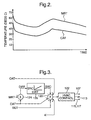
- FIG. 2 graphically depicts the MRT and CAT inputs of Figure 1 for a vehicle operating at varying load under controlled environmental conditions, including an outside air temperature (OAT) of 110°F and a solar load of 800W/m 2 .
- OAT outside air temperature
- the solar load elevates the mean radiant temperature above the cabin air temperature, resulting in a difference between MRT and CAT which remains relatively constant as shown regardless of other vehicle operating conditions. As the solar load increases, the difference between MRT and CAT also increases, and vice-versa.
- FIG 3 depicts a block diagram of a climate control solar compensation algorithm carried out by the control unit 90 of Figure 1 using the MRT and CAT inputs.
- the control is illustrated in the context of a "program number" control where various signals such as OAT, CAT and SET are combined in summing block 120 to form an input to an HVAC control routine, represented in Figure 3 by the block 122.
- the block 12 may be implemented with calibrated look-up tables responsive to the program number input, and produces output signals on lines 107, 113, 115, 117 for controlling the blower motor speed, the outlet air temperature, and the air discharge mode.
- the program number varies in inverse relationship to the desired cooling capacity; thus, the program number increases with increasing values of CAT and SET, and decreases with increasing values of OAT and solar radiation correction SRC.
- a calibrated constant K may also be introduced as shown.
- a summing block 124 computes the difference DIFF between the MRT and CAT inputs, and supplies DIFF as an input to solar correction block 126.
- the solar correction block 126 may be implemented as a look-up table as shown, and develops the solar radiation correction term SRC as a calibrated but generally proportional function of DIFF.
- control of this invention provides an improved method of measuring the heating of a vehicle cabin due to solar radiation and for compensating the operation of a climate control in a way that contributes to increased passenger comfort.
- the method provides a more accurate measure of solar radiation, and can be implemented at a substantial cost savings compared to a conventional control.
- the control is equally applicable to a so-called manual control system, and may be implemented with automatic climate control algorithms other than the disclosed "program number" approach.
- control is also applicable to systems that incorporate a fixed displacement compressor in place of the variable capacity compressor 12, and so on.
- control methods incorporating these and other modifications may fall within the scope of this invention, which is defined by the appended claims.
Abstract
Description
- This invention relates to motor vehicle climate control, and more particularly to method of compensating the operation of the system for solar radiation.
- Vehicle climate control systems typically include a microprocessor-based controller programmed to adjust the cooling capacity of the system based on a measure of the cabin air temperature and various other factors such as outside air temperature and solar loading. Solar loading is ordinarily measured by mounting one or more photovoltaic sensors under the windshield of the passenger compartment for producing a signal representative of the solar load on the passenger compartment. In current practice, the photovoltaic sensor comprises sensing element packaged in a spherical housing made of translucent plastic that passes attenuated visible light. The sensing element produces an electrical voltage that varies with the intensity of the impinging light, and the controller uses the voltage as a measure of solar loading.
- Although a photovoltaic sensor of the type described above can provide a reliable measure of incident visible light, it does not necessarily provide a true indication of solar loading because it fails to take into account infrared radiation due to hot ambient and passenger compartment surfaces. Additionally, photovoltaic sensors are relatively expensive compared to mass-produced devices such as thermocouples or thermistors. Accordingly, what is needed is a more accurate and cost-effective way of detecting passenger compartment heating due to solar radiation and compensating the cooling capacity of a climate control system accordingly.
- The present invention is directed to an improved vehicle climate control that is compensated for direct and indirect infrared heat loading due to solar radiation using a mean radiant temperature sensor and a cabin air temperature sensor. The mean radiant temperature sensor include a temperature responsive element such as a thermistor enclosed in a hollow spherical housing that blocks visible light but absorbs infrared radiation. The difference between the mean radiant temperature and the cabin air temperature provides a measure of the total infrared heat loading on the cabin and is used to increase the cooling capacity of the climate control system.
-
- Figure 1 is a block diagram of a vehicle climate control according to this invention, including a mean radiant temperature sensor and a microprocessor based climate control unit.
- Figure 2 is a graph depicting the relationship between the mean radiant temperature and cabin air temperature in a vehicle subject to a constant level of solar radiation.
- Figure 3 is a block diagram depicting a method of operation carried out by the climate control unit of Figure 1 according to this invention.
-
- Referring to Figure 1, the method of this invention is described in the context of an automatic climate control system, generally designated by the
reference numeral 10. In the illustrated embodiment, thesystem 10 includes a variablecapacity refrigerant compressor 12 having astroke control valve 17 that is electrically activated to control the compressor pumping capacity. The compressor input shaft is coupled to adrive pulley 14 via an electrically activatedclutch 16, and thedrive pulley 14 is coupled to a rotary shaft of the vehicle engine (not shown) viadrive belt 18, so that thecompressor 12 can be turned on or off by respectively engaging or disengaging theclutch 16. In systems utilizing a fixed displacement compressor instead of thevariable displacement compressor 12, the compressor pumping capacity may be regulated by cycling theclutch 16 on and off. Thesystem 10 further includes acondenser 20, anorifice tube 22, anevaporator 24, and an accumulator/dehydrator 26 arranged in order between thecompressor discharge port 28 andsuction port 30. Theelectric drive motor 34 ofcooling fan 32 is controlled to provide supplemental airflow for removing heat from high pressure refrigerant incondenser 20. Theorifice tube 22 allows the cooled high pressure refrigerant inline 38 to expand in isenthalpic fashion before passing through theevaporator 24. The accumulator/dehydrator 26 separates low pressure gaseous and liquid refrigerant, directs gaseous refrigerant to thecompressor suction port 30, and stores excess refrigerant that is not in circulation. In an alternative system configuration, theorifice tube 22 is replaced with a thermostatic expansion valve (TXV); in this case, the accumulator/dehydrator 26 is omitted, and a receiver/drier (R/D) is inserted inline 38 upstream of the TXV to ensure that sub-cooled liquid refrigerant is available at the TXV inlet. - The
evaporator 24 is formed as an array of finned refrigerant conducting tubes, and anair intake duct 40 disposed on one side ofevaporator 24 houses a motor drivenventilation blower 42 for forcing air past the evaporator tubes. Theduct 40 is bifurcated upstream of theblower 42, and an inletair control door 44 is adjustable as shown to control inlet air mixing; depending on the door position, outside air may enterblower 42 throughduct leg 44a as indicated byarrow 48, and passenger compartment air may enterblower 42 throughduct leg 44b as indicated byarrow 50. - An
air outlet duct 52 disposed on the downstream side ofblower 42 andevaporator 24 houses aheater core 54 formed as an array of finned tubes through which flows engine coolant. Theheater core 54 effectively bifurcates theoutlet duct 52, and are-heat door 56 next toheater core 54 is adjustable as shown to divide the airflow through and around theheater core 54. The heated and un-heated air portions are mixed in aplenum portion 62 downstream ofre-heat door 56, and a pair ofmode control doors defrost outlet 68, apanel outlet 70, and aheater outlet 72. Themode control door 64 is adjustable as shown to switch the outlet air between defrost andpanel outlets arrows mode control door 66 is adjustable as shown to control airflow through theheater outlet 72, as indicted byarrow 82. - The above-described components of
system 10 are controlled by the microprocessor-basedcontrol unit 90, which is responsive to a number of inputs, including outside air temperature (OAT), cabin air temperature (CAT), a an occupant adjustable set temperature (SET) and mean radiant temperature (MRT). Other inputs not shown in Figure 1 include the usual operator demand inputs, such as the override controls for air delivery mode, air inlet door position and blower motor speed. The OAT input may be provided by any temperature sensor responsive the outside or ambient air temperature, while the CAT input is provided by a conventional aspiratedtemperature sensor 92 located in the cabin instrument panel. The MRT input is provided by a meanradiant temperature sensor 94 mounted atop theinstrument panel 96 under thewindshield 98. Thesensor 94 simply comprises a temperature responsive element such as a thermistor 94a enclosed in a hollow spherical or semi-sphericalblack housing 94b that blocks visible light but absorbs infrared radiation produced by sunlight passing throughwindshield 98 or by solar heated objects in or near the vehicle cabin. As the radiation is absorbed by the black mass of the sensor housing 94b, the housing 9b emits heat to both the cabin air and the air within thehousing 94b, and the air temperature detected bythermistor 94a provides a reasonably accurate estimate of the mean radiant temperature in the cabin. Although technically, mean radiant temperature is also a function of the airflow rate over thesensor 94, thesensor 94 is mounted in a location where the air velocity is very small so as to render negligible any airflow effects. In the illustrated embodiment, for example, thesensor 94 is mounted under thewindshield 98 away from any air discharge outlets of theclimate control system 10. - In response to the inputs mentioned above, the
control unit 90 develops output signals for controlling thecompressor clutch 16, thecapacity control valve 17, thefan motor 34,blower motor 43, and theair control doors clutch 16,stroke control valve 17,condenser fan motor 34, andblower motor 43 appear onlines air control doors corresponding actuators - As indicated above, the present invention is particularly directed to a way of using the mean radiant temperature in the vehicle cabin to determine and compensate for solar loading. Figure 2 graphically depicts the MRT and CAT inputs of Figure 1 for a vehicle operating at varying load under controlled environmental conditions, including an outside air temperature (OAT) of 110°F and a solar load of 800W/m2. The solar load elevates the mean radiant temperature above the cabin air temperature, resulting in a difference between MRT and CAT which remains relatively constant as shown regardless of other vehicle operating conditions. As the solar load increases, the difference between MRT and CAT also increases, and vice-versa.
- Figure 3 depicts a block diagram of a climate control solar compensation algorithm carried out by the
control unit 90 of Figure 1 using the MRT and CAT inputs. The control is illustrated in the context of a "program number" control where various signals such as OAT, CAT and SET are combined insumming block 120 to form an input to an HVAC control routine, represented in Figure 3 by theblock 122. Theblock 12 may be implemented with calibrated look-up tables responsive to the program number input, and produces output signals onlines summing block 124 computes the difference DIFF between the MRT and CAT inputs, and supplies DIFF as an input tosolar correction block 126. Thesolar correction block 126 may be implemented as a look-up table as shown, and develops the solar radiation correction term SRC as a calibrated but generally proportional function of DIFF. - In summary, the control of this invention provides an improved method of measuring the heating of a vehicle cabin due to solar radiation and for compensating the operation of a climate control in a way that contributes to increased passenger comfort. The method provides a more accurate measure of solar radiation, and can be implemented at a substantial cost savings compared to a conventional control. While this invention has been described in reference to the illustrated embodiment, it is expected that various modifications in addition to those mentioned above will occur to those skilled in the art. For example, the control is equally applicable to a so-called manual control system, and may be implemented with automatic climate control algorithms other than the disclosed "program number" approach. Likewise, the control is also applicable to systems that incorporate a fixed displacement compressor in place of the
variable capacity compressor 12, and so on. Thus, it will be understood that control methods incorporating these and other modifications may fall within the scope of this invention, which is defined by the appended claims.
Claims (4)
- A method of operation of a climate control system for a vehicle cabin (10), including a controller (90) for adjusting a cooling capacity of system to condition air in said cabin, the method of operation comprising the steps of:measuring a mean radiant temperature in said cabin (94);measuring an air temperature in said cabin (92);computing a difference between said mean radiant temperature and said air temperature (124);estimating a solar radiation intensity according to said difference (126); andadjusting said cooling capacity based on the estimated solar radiation intensity (120, 122).
- The method of operation of Claim 1, wherein the cabin is bounded in part by a windshield (98), and the step of measuring the mean radiant temperature includes the steps of:placing a hollow spherical or semi-spherical housing (94b) that blocks visible light but absorbs infrared radiation in the cabin under the windshield (98); andmeasuring said mean radiant temperature according to a temperature of air inside said housing (94a).
- The method of operation of Claim 2, including the step of:measuring the temperature of air inside said housing (94b) with a thermistor or thermocouple (94a).
- The method of operation of Claim 3, wherein the step of estimating the solar radiation intensity includes the steps of:storing a predefined relationship between said difference and said solar radiation intensity (126); andretrieving a stored value of radiation intensity based on the computed difference (124, 126).
Applications Claiming Priority (2)
| Application Number | Priority Date | Filing Date | Title |
|---|---|---|---|
| US10/829,543 US6966498B2 (en) | 2004-04-22 | 2004-04-22 | Solar radiation compensation method for a vehicle climate control |
| US829543 | 2004-04-22 |
Publications (2)
| Publication Number | Publication Date |
|---|---|
| EP1588874A1 true EP1588874A1 (en) | 2005-10-26 |
| EP1588874B1 EP1588874B1 (en) | 2008-11-12 |
Family
ID=34938147
Family Applications (1)
| Application Number | Title | Priority Date | Filing Date |
|---|---|---|---|
| EP05075819A Not-in-force EP1588874B1 (en) | 2004-04-22 | 2005-04-11 | Solar radiation compensation method for a vehicle climate control |
Country Status (4)
| Country | Link |
|---|---|
| US (1) | US6966498B2 (en) |
| EP (1) | EP1588874B1 (en) |
| AT (1) | ATE413979T1 (en) |
| DE (1) | DE602005010930D1 (en) |
Families Citing this family (15)
| Publication number | Priority date | Publication date | Assignee | Title |
|---|---|---|---|---|
| DE10256866B3 (en) * | 2002-12-04 | 2004-01-08 | Daimlerchrysler Ag | Method for solar radiation-dependent air conditioning of the vehicle interior |
| DE10302285B4 (en) * | 2003-01-22 | 2006-05-04 | Preh Gmbh | Method for determining the interior temperature of a motor vehicle passenger compartment, arrangement for carrying out the method and temperature sensor |
| DE602005005316T2 (en) * | 2005-07-05 | 2009-03-26 | C.R.F. Società Consortile per Azioni, Orbassano | Air conditioning control system for motor vehicles |
| EP1953019B1 (en) * | 2005-10-21 | 2010-05-19 | Toyota Jidosha Kabushiki Kaisha | Device for cooling electric device mounted on vehicle |
| FR2917012B1 (en) * | 2007-06-08 | 2012-12-14 | Renault Sas | AIR CONDITIONING SYSTEM FOR A VEHICLE WITH ENHANCED SUNNY CORRECTION |
| US20100019050A1 (en) * | 2008-07-25 | 2010-01-28 | Gm Global Technology Operations, Inc. | Automatic Climate Control for a Vehicle |
| JP5345406B2 (en) * | 2009-01-14 | 2013-11-20 | カルソニックカンセイ株式会社 | Air conditioner for vehicles |
| JP2013057476A (en) * | 2011-09-09 | 2013-03-28 | Toshiba Corp | Pmv estimating device and program thereof |
| US9417638B2 (en) * | 2012-12-20 | 2016-08-16 | Automotive Research & Testing Center | Intelligent thermostatic control method and device for an air conditioner blowing cold and hot air |
| US10543731B2 (en) * | 2013-02-15 | 2020-01-28 | Ford Global Technologies, Llc | Auxiliary HVAC system for a vehicle |
| JP5937039B2 (en) * | 2013-05-10 | 2016-06-22 | 東京瓦斯株式会社 | Pyranometer |
| US20150025738A1 (en) * | 2013-07-22 | 2015-01-22 | GM Global Technology Operations LLC | Methods and apparatus for automatic climate control in a vehicle based on clothing insulative factor |
| CN107097607A (en) * | 2017-05-24 | 2017-08-29 | 苏州冷晨智能科技有限公司 | The Air Condition Compressor for Electric Vehicle system and its control method of temperature stabilization |
| JP2022052822A (en) * | 2020-09-24 | 2022-04-05 | トヨタ自動車株式会社 | Air conditioner for vehicle |
| CN114237329B (en) * | 2022-01-11 | 2022-08-26 | 中国飞机强度研究所 | Temperature control system and control method for aircraft solar radiation test |
Citations (3)
| Publication number | Priority date | Publication date | Assignee | Title |
|---|---|---|---|---|
| US4919328A (en) * | 1988-03-22 | 1990-04-24 | Nissan Motor Co., Ltd. | Automobile air conditioning system |
| EP0968855A1 (en) * | 1998-06-04 | 2000-01-05 | Sanden Corporation | Air conditioning apparatus for vehicle |
| DE10208851A1 (en) * | 2001-03-02 | 2002-09-19 | Fiat Ricerche | Control device for a room air conditioner, in particular for the interior of a transport vehicle |
Family Cites Families (11)
| Publication number | Priority date | Publication date | Assignee | Title |
|---|---|---|---|---|
| US4441405A (en) * | 1981-03-12 | 1984-04-10 | Nissan Motor Company, Limited | Solar radiation heat influx sensor for an automotive vehicle |
| JP2575846B2 (en) * | 1988-10-28 | 1997-01-29 | マツダ株式会社 | Control unit for vehicle air conditioning |
| FR2639238B1 (en) * | 1988-11-21 | 1991-02-22 | Technomed Int Sa | APPARATUS FOR SURGICAL TREATMENT OF TISSUES BY HYPERTHERMIA, PREFERABLY THE PROSTATE, COMPRISING MEANS OF THERMAL PROTECTION COMPRISING PREFERABLY RADIOREFLECTIVE SCREEN MEANS |
| JP3239378B2 (en) * | 1991-08-09 | 2001-12-17 | 株式会社デンソー | Vehicle air conditioner |
| US5810078A (en) * | 1993-02-11 | 1998-09-22 | Saab Automobile Ab | Apparatus and method for the environmental control of vehicle interiors |
| US5553661A (en) * | 1995-10-23 | 1996-09-10 | Delco Electronics Corporation | Solar position correction for climate control system |
| JP3492849B2 (en) * | 1996-05-01 | 2004-02-03 | サンデン株式会社 | Vehicle air conditioner |
| DE19617562C1 (en) * | 1996-05-02 | 1997-05-15 | Daimler Benz Ag | Vehicle air conditioning unit |
| US6220517B1 (en) * | 1998-04-22 | 2001-04-24 | Denso Corporation | Air-conditioning device |
| JP2001191779A (en) * | 1999-09-03 | 2001-07-17 | Denso Corp | Air conditioner for vehicle |
| FR2806036B1 (en) * | 2000-03-07 | 2002-11-15 | Valeo Electronique | IMPROVED REGULATION OF TEMPERATURE, SPEED AND DISTRIBUTION OF VENTILATED AIR IN A MOTOR VEHICLE INTERIOR |
-
2004
- 2004-04-22 US US10/829,543 patent/US6966498B2/en active Active
-
2005
- 2005-04-11 DE DE602005010930T patent/DE602005010930D1/en active Active
- 2005-04-11 EP EP05075819A patent/EP1588874B1/en not_active Not-in-force
- 2005-04-11 AT AT05075819T patent/ATE413979T1/en not_active IP Right Cessation
Patent Citations (3)
| Publication number | Priority date | Publication date | Assignee | Title |
|---|---|---|---|---|
| US4919328A (en) * | 1988-03-22 | 1990-04-24 | Nissan Motor Co., Ltd. | Automobile air conditioning system |
| EP0968855A1 (en) * | 1998-06-04 | 2000-01-05 | Sanden Corporation | Air conditioning apparatus for vehicle |
| DE10208851A1 (en) * | 2001-03-02 | 2002-09-19 | Fiat Ricerche | Control device for a room air conditioner, in particular for the interior of a transport vehicle |
Also Published As
| Publication number | Publication date |
|---|---|
| EP1588874B1 (en) | 2008-11-12 |
| US20050235668A1 (en) | 2005-10-27 |
| ATE413979T1 (en) | 2008-11-15 |
| US6966498B2 (en) | 2005-11-22 |
| DE602005010930D1 (en) | 2008-12-24 |
Similar Documents
| Publication | Publication Date | Title |
|---|---|---|
| EP1588874B1 (en) | Solar radiation compensation method for a vehicle climate control | |
| US7958740B2 (en) | Vehicular air-conditioner | |
| US7121103B2 (en) | Vehicle air conditioning system | |
| US5810078A (en) | Apparatus and method for the environmental control of vehicle interiors | |
| US7337622B2 (en) | Humidity-based defog control method for a vehicle climate control system | |
| US7997331B2 (en) | Air-conditioning system | |
| US8302417B2 (en) | Air conditioning system with cold thermal storage and evaporator temperature control | |
| US7556090B2 (en) | Vehicular air-conditioner providing a comfortable condition for a passenger | |
| US6293116B1 (en) | Humidity control method for a variable capacity vehicle climate control system | |
| EP1258375A1 (en) | Automatic windglass fog prevention method for a vehicle climate control system | |
| US9452661B2 (en) | Vehicle air conditioning system | |
| US5209079A (en) | Control apparatus for air conditioner used for vehicles | |
| US8682527B2 (en) | Cooling system compressor with variable operating range | |
| US7886552B2 (en) | Compressor cycle control method for a vehicle air conditioning system | |
| US6978629B2 (en) | Vehicle air conditioner | |
| JP4784573B2 (en) | TECHNICAL FIELD The present invention relates to a vehicle air conditioner. | |
| US6434958B1 (en) | Ambient humidity compensation method for a vehicle climate control system | |
| US6427465B1 (en) | Compressor control system and method | |
| US7650927B2 (en) | Outlet temperature calculation correction from ambient/water temperature | |
| JP3417035B2 (en) | Vehicle air conditioner | |
| JP2004230988A (en) | Air-conditioner for vehicle | |
| US6862893B1 (en) | Automatic defog control method for a vehicle climate control system | |
| EP1362725B1 (en) | Control device | |
| US6116511A (en) | Method of initializing an in-car temperature sensor for a climate control system | |
| JP5310323B2 (en) | Control method for vehicle air conditioner |
Legal Events
| Date | Code | Title | Description |
|---|---|---|---|
| PUAI | Public reference made under article 153(3) epc to a published international application that has entered the european phase |
Free format text: ORIGINAL CODE: 0009012 |
|
| AK | Designated contracting states |
Kind code of ref document: A1 Designated state(s): AT BE BG CH CY CZ DE DK EE ES FI FR GB GR HU IE IS IT LI LT LU MC NL PL PT RO SE SI SK TR |
|
| AX | Request for extension of the european patent |
Extension state: AL BA HR LV MK YU |
|
| 17P | Request for examination filed |
Effective date: 20060426 |
|
| AKX | Designation fees paid |
Designated state(s): AT BE BG CH CY CZ DE DK EE ES FI FR GB GR HU IE IS IT LI LT LU MC NL PL PT RO SE SI SK TR |
|
| 17Q | First examination report despatched |
Effective date: 20061222 |
|
| GRAP | Despatch of communication of intention to grant a patent |
Free format text: ORIGINAL CODE: EPIDOSNIGR1 |
|
| GRAS | Grant fee paid |
Free format text: ORIGINAL CODE: EPIDOSNIGR3 |
|
| GRAA | (expected) grant |
Free format text: ORIGINAL CODE: 0009210 |
|
| AK | Designated contracting states |
Kind code of ref document: B1 Designated state(s): AT BE BG CH CY CZ DE DK EE ES FI FR GB GR HU IE IS IT LI LT LU MC NL PL PT RO SE SI SK TR |
|
| REG | Reference to a national code |
Ref country code: GB Ref legal event code: FG4D |
|
| REG | Reference to a national code |
Ref country code: CH Ref legal event code: EP |
|
| REG | Reference to a national code |
Ref country code: IE Ref legal event code: FG4D |
|
| REF | Corresponds to: |
Ref document number: 602005010930 Country of ref document: DE Date of ref document: 20081224 Kind code of ref document: P |
|
| LTIE | Lt: invalidation of european patent or patent extension |
Effective date: 20081112 |
|
| PG25 | Lapsed in a contracting state [announced via postgrant information from national office to epo] |
Ref country code: LT Free format text: LAPSE BECAUSE OF FAILURE TO SUBMIT A TRANSLATION OF THE DESCRIPTION OR TO PAY THE FEE WITHIN THE PRESCRIBED TIME-LIMIT Effective date: 20081112 Ref country code: ES Free format text: LAPSE BECAUSE OF FAILURE TO SUBMIT A TRANSLATION OF THE DESCRIPTION OR TO PAY THE FEE WITHIN THE PRESCRIBED TIME-LIMIT Effective date: 20090223 Ref country code: AT Free format text: LAPSE BECAUSE OF FAILURE TO SUBMIT A TRANSLATION OF THE DESCRIPTION OR TO PAY THE FEE WITHIN THE PRESCRIBED TIME-LIMIT Effective date: 20081112 |
|
| NLV1 | Nl: lapsed or annulled due to failure to fulfill the requirements of art. 29p and 29m of the patents act | ||
| PG25 | Lapsed in a contracting state [announced via postgrant information from national office to epo] |
Ref country code: FI Free format text: LAPSE BECAUSE OF FAILURE TO SUBMIT A TRANSLATION OF THE DESCRIPTION OR TO PAY THE FEE WITHIN THE PRESCRIBED TIME-LIMIT Effective date: 20081112 Ref country code: SI Free format text: LAPSE BECAUSE OF FAILURE TO SUBMIT A TRANSLATION OF THE DESCRIPTION OR TO PAY THE FEE WITHIN THE PRESCRIBED TIME-LIMIT Effective date: 20081112 Ref country code: NL Free format text: LAPSE BECAUSE OF FAILURE TO SUBMIT A TRANSLATION OF THE DESCRIPTION OR TO PAY THE FEE WITHIN THE PRESCRIBED TIME-LIMIT Effective date: 20081112 Ref country code: IS Free format text: LAPSE BECAUSE OF FAILURE TO SUBMIT A TRANSLATION OF THE DESCRIPTION OR TO PAY THE FEE WITHIN THE PRESCRIBED TIME-LIMIT Effective date: 20090312 Ref country code: PL Free format text: LAPSE BECAUSE OF FAILURE TO SUBMIT A TRANSLATION OF THE DESCRIPTION OR TO PAY THE FEE WITHIN THE PRESCRIBED TIME-LIMIT Effective date: 20081112 |
|
| PG25 | Lapsed in a contracting state [announced via postgrant information from national office to epo] |
Ref country code: BG Free format text: LAPSE BECAUSE OF FAILURE TO SUBMIT A TRANSLATION OF THE DESCRIPTION OR TO PAY THE FEE WITHIN THE PRESCRIBED TIME-LIMIT Effective date: 20090212 Ref country code: RO Free format text: LAPSE BECAUSE OF FAILURE TO SUBMIT A TRANSLATION OF THE DESCRIPTION OR TO PAY THE FEE WITHIN THE PRESCRIBED TIME-LIMIT Effective date: 20081112 Ref country code: EE Free format text: LAPSE BECAUSE OF FAILURE TO SUBMIT A TRANSLATION OF THE DESCRIPTION OR TO PAY THE FEE WITHIN THE PRESCRIBED TIME-LIMIT Effective date: 20081112 Ref country code: DK Free format text: LAPSE BECAUSE OF FAILURE TO SUBMIT A TRANSLATION OF THE DESCRIPTION OR TO PAY THE FEE WITHIN THE PRESCRIBED TIME-LIMIT Effective date: 20081112 Ref country code: BE Free format text: LAPSE BECAUSE OF FAILURE TO SUBMIT A TRANSLATION OF THE DESCRIPTION OR TO PAY THE FEE WITHIN THE PRESCRIBED TIME-LIMIT Effective date: 20081112 |
|
| PG25 | Lapsed in a contracting state [announced via postgrant information from national office to epo] |
Ref country code: SE Free format text: LAPSE BECAUSE OF FAILURE TO SUBMIT A TRANSLATION OF THE DESCRIPTION OR TO PAY THE FEE WITHIN THE PRESCRIBED TIME-LIMIT Effective date: 20090212 Ref country code: PT Free format text: LAPSE BECAUSE OF FAILURE TO SUBMIT A TRANSLATION OF THE DESCRIPTION OR TO PAY THE FEE WITHIN THE PRESCRIBED TIME-LIMIT Effective date: 20090413 Ref country code: CZ Free format text: LAPSE BECAUSE OF FAILURE TO SUBMIT A TRANSLATION OF THE DESCRIPTION OR TO PAY THE FEE WITHIN THE PRESCRIBED TIME-LIMIT Effective date: 20081112 |
|
| PLBE | No opposition filed within time limit |
Free format text: ORIGINAL CODE: 0009261 |
|
| STAA | Information on the status of an ep patent application or granted ep patent |
Free format text: STATUS: NO OPPOSITION FILED WITHIN TIME LIMIT |
|
| PG25 | Lapsed in a contracting state [announced via postgrant information from national office to epo] |
Ref country code: SK Free format text: LAPSE BECAUSE OF FAILURE TO SUBMIT A TRANSLATION OF THE DESCRIPTION OR TO PAY THE FEE WITHIN THE PRESCRIBED TIME-LIMIT Effective date: 20081112 |
|
| 26N | No opposition filed |
Effective date: 20090813 |
|
| REG | Reference to a national code |
Ref country code: CH Ref legal event code: PL |
|
| PG25 | Lapsed in a contracting state [announced via postgrant information from national office to epo] |
Ref country code: LI Free format text: LAPSE BECAUSE OF NON-PAYMENT OF DUE FEES Effective date: 20090430 Ref country code: CH Free format text: LAPSE BECAUSE OF NON-PAYMENT OF DUE FEES Effective date: 20090430 |
|
| PG25 | Lapsed in a contracting state [announced via postgrant information from national office to epo] |
Ref country code: MC Free format text: LAPSE BECAUSE OF NON-PAYMENT OF DUE FEES Effective date: 20090430 Ref country code: IE Free format text: LAPSE BECAUSE OF NON-PAYMENT OF DUE FEES Effective date: 20090411 |
|
| PG25 | Lapsed in a contracting state [announced via postgrant information from national office to epo] |
Ref country code: GR Free format text: LAPSE BECAUSE OF FAILURE TO SUBMIT A TRANSLATION OF THE DESCRIPTION OR TO PAY THE FEE WITHIN THE PRESCRIBED TIME-LIMIT Effective date: 20090213 |
|
| PG25 | Lapsed in a contracting state [announced via postgrant information from national office to epo] |
Ref country code: IT Free format text: LAPSE BECAUSE OF FAILURE TO SUBMIT A TRANSLATION OF THE DESCRIPTION OR TO PAY THE FEE WITHIN THE PRESCRIBED TIME-LIMIT Effective date: 20081112 |
|
| PG25 | Lapsed in a contracting state [announced via postgrant information from national office to epo] |
Ref country code: LU Free format text: LAPSE BECAUSE OF NON-PAYMENT OF DUE FEES Effective date: 20090411 |
|
| PG25 | Lapsed in a contracting state [announced via postgrant information from national office to epo] |
Ref country code: HU Free format text: LAPSE BECAUSE OF FAILURE TO SUBMIT A TRANSLATION OF THE DESCRIPTION OR TO PAY THE FEE WITHIN THE PRESCRIBED TIME-LIMIT Effective date: 20090513 |
|
| PG25 | Lapsed in a contracting state [announced via postgrant information from national office to epo] |
Ref country code: TR Free format text: LAPSE BECAUSE OF FAILURE TO SUBMIT A TRANSLATION OF THE DESCRIPTION OR TO PAY THE FEE WITHIN THE PRESCRIBED TIME-LIMIT Effective date: 20081112 |
|
| PG25 | Lapsed in a contracting state [announced via postgrant information from national office to epo] |
Ref country code: CY Free format text: LAPSE BECAUSE OF FAILURE TO SUBMIT A TRANSLATION OF THE DESCRIPTION OR TO PAY THE FEE WITHIN THE PRESCRIBED TIME-LIMIT Effective date: 20081112 |
|
| REG | Reference to a national code |
Ref country code: DE Ref legal event code: R082 Ref document number: 602005010930 Country of ref document: DE Representative=s name: BRP RENAUD UND PARTNER MBB RECHTSANWAELTE PATE, DE Ref country code: DE Ref legal event code: R082 Ref document number: 602005010930 Country of ref document: DE Representative=s name: BRP RENAUD UND PARTNER MBB, DE Ref country code: DE Ref legal event code: R081 Ref document number: 602005010930 Country of ref document: DE Owner name: MAHLE INTERNATIONAL GMBH, DE Free format text: FORMER OWNER: DELPHI TECHNOLOGIES, INC., TROY, MICH., US |
|
| REG | Reference to a national code |
Ref country code: FR Ref legal event code: PLFP Year of fee payment: 12 |
|
| REG | Reference to a national code |
Ref country code: GB Ref legal event code: 732E Free format text: REGISTERED BETWEEN 20161208 AND 20161214 |
|
| REG | Reference to a national code |
Ref country code: FR Ref legal event code: PLFP Year of fee payment: 13 |
|
| REG | Reference to a national code |
Ref country code: FR Ref legal event code: TP Owner name: MAHLE INTERNATIONAL GMBH, DE Effective date: 20180103 |
|
| REG | Reference to a national code |
Ref country code: FR Ref legal event code: PLFP Year of fee payment: 14 |
|
| PGFP | Annual fee paid to national office [announced via postgrant information from national office to epo] |
Ref country code: FR Payment date: 20190429 Year of fee payment: 15 |
|
| PGFP | Annual fee paid to national office [announced via postgrant information from national office to epo] |
Ref country code: DE Payment date: 20190628 Year of fee payment: 15 Ref country code: GB Payment date: 20190429 Year of fee payment: 15 |
|
| REG | Reference to a national code |
Ref country code: DE Ref legal event code: R119 Ref document number: 602005010930 Country of ref document: DE |
|
| PG25 | Lapsed in a contracting state [announced via postgrant information from national office to epo] |
Ref country code: FR Free format text: LAPSE BECAUSE OF NON-PAYMENT OF DUE FEES Effective date: 20200430 Ref country code: DE Free format text: LAPSE BECAUSE OF NON-PAYMENT OF DUE FEES Effective date: 20201103 |
|
| GBPC | Gb: european patent ceased through non-payment of renewal fee |
Effective date: 20200411 |
|
| PG25 | Lapsed in a contracting state [announced via postgrant information from national office to epo] |
Ref country code: GB Free format text: LAPSE BECAUSE OF NON-PAYMENT OF DUE FEES Effective date: 20200411 |